EP2988928B1 - Machine for the continuous manufacture of tubular box bodies, notably based on cardboard or the like - Google Patents
Machine for the continuous manufacture of tubular box bodies, notably based on cardboard or the like Download PDFInfo
- Publication number
- EP2988928B1 EP2988928B1 EP14727575.4A EP14727575A EP2988928B1 EP 2988928 B1 EP2988928 B1 EP 2988928B1 EP 14727575 A EP14727575 A EP 14727575A EP 2988928 B1 EP2988928 B1 EP 2988928B1
- Authority
- EP
- European Patent Office
- Prior art keywords
- mandrel
- machine according
- forming mandrel
- longitudinal
- machine
- Prior art date
- Legal status (The legal status is an assumption and is not a legal conclusion. Google has not performed a legal analysis and makes no representation as to the accuracy of the status listed.)
- Active
Links
- 238000004519 manufacturing process Methods 0.000 title claims description 15
- 239000000463 material Substances 0.000 claims description 53
- 238000005096 rolling process Methods 0.000 claims description 11
- 238000004026 adhesive bonding Methods 0.000 claims description 10
- 238000011161 development Methods 0.000 claims description 10
- 238000003825 pressing Methods 0.000 claims description 9
- 238000011144 upstream manufacturing Methods 0.000 claims description 8
- 239000003292 glue Substances 0.000 claims description 7
- 230000000295 complement effect Effects 0.000 claims description 5
- 239000013013 elastic material Substances 0.000 claims description 5
- 238000003466 welding Methods 0.000 claims description 5
- 244000043261 Hevea brasiliensis Species 0.000 claims description 3
- 229920003052 natural elastomer Polymers 0.000 claims description 3
- 229920001194 natural rubber Polymers 0.000 claims description 3
- 229920002635 polyurethane Polymers 0.000 claims description 3
- 239000004814 polyurethane Substances 0.000 claims description 3
- 229920003051 synthetic elastomer Polymers 0.000 claims description 3
- 239000005061 synthetic rubber Substances 0.000 claims description 3
- XLYOFNOQVPJJNP-UHFFFAOYSA-N water Substances O XLYOFNOQVPJJNP-UHFFFAOYSA-N 0.000 claims description 3
- KWGRBVOPPLSCSI-WPRPVWTQSA-N (-)-ephedrine Chemical compound CN[C@@H](C)[C@H](O)C1=CC=CC=C1 KWGRBVOPPLSCSI-WPRPVWTQSA-N 0.000 description 13
- 230000004888 barrier function Effects 0.000 description 6
- 238000013461 design Methods 0.000 description 5
- 238000012423 maintenance Methods 0.000 description 4
- 230000008901 benefit Effects 0.000 description 3
- 238000007789 sealing Methods 0.000 description 3
- 230000008859 change Effects 0.000 description 2
- 238000010030 laminating Methods 0.000 description 2
- 238000004806 packaging method and process Methods 0.000 description 2
- 239000002994 raw material Substances 0.000 description 2
- 238000013519 translation Methods 0.000 description 2
- 230000015572 biosynthetic process Effects 0.000 description 1
- 239000011365 complex material Substances 0.000 description 1
- 239000002131 composite material Substances 0.000 description 1
- 238000006073 displacement reaction Methods 0.000 description 1
- 239000012528 membrane Substances 0.000 description 1
- 239000002184 metal Substances 0.000 description 1
- 238000000034 method Methods 0.000 description 1
- 238000012986 modification Methods 0.000 description 1
- 230000004048 modification Effects 0.000 description 1
- 230000000704 physical effect Effects 0.000 description 1
- 230000001737 promoting effect Effects 0.000 description 1
- 238000007493 shaping process Methods 0.000 description 1
- 230000003068 static effect Effects 0.000 description 1
- 238000002604 ultrasonography Methods 0.000 description 1
- 239000002699 waste material Substances 0.000 description 1
Images


Classifications
-
- B—PERFORMING OPERATIONS; TRANSPORTING
- B31—MAKING ARTICLES OF PAPER, CARDBOARD OR MATERIAL WORKED IN A MANNER ANALOGOUS TO PAPER; WORKING PAPER, CARDBOARD OR MATERIAL WORKED IN A MANNER ANALOGOUS TO PAPER
- B31F—MECHANICAL WORKING OR DEFORMATION OF PAPER, CARDBOARD OR MATERIAL WORKED IN A MANNER ANALOGOUS TO PAPER
- B31F7/00—Processes not otherwise provided for
- B31F7/004—Making tubes
-
- B—PERFORMING OPERATIONS; TRANSPORTING
- B31—MAKING ARTICLES OF PAPER, CARDBOARD OR MATERIAL WORKED IN A MANNER ANALOGOUS TO PAPER; WORKING PAPER, CARDBOARD OR MATERIAL WORKED IN A MANNER ANALOGOUS TO PAPER
- B31F—MECHANICAL WORKING OR DEFORMATION OF PAPER, CARDBOARD OR MATERIAL WORKED IN A MANNER ANALOGOUS TO PAPER
- B31F1/00—Mechanical deformation without removing material, e.g. in combination with laminating
- B31F1/0003—Shaping by bending, folding, twisting, straightening, flattening or rim-rolling; Shaping by bending, folding or rim-rolling combined with joining; Apparatus therefor
- B31F1/0045—Bending or folding combined with joining
- B31F1/0048—Bending plates, sheets or webs at right angles to the axis of the article being formed and joining the edges
- B31F1/0061—Bending plates, sheets or webs at right angles to the axis of the article being formed and joining the edges for making articles of indefinite length
- B31F1/0064—Bending plates, sheets or webs at right angles to the axis of the article being formed and joining the edges for making articles of indefinite length using internal forming surfaces, on, e.g. mandrels
-
- B—PERFORMING OPERATIONS; TRANSPORTING
- B31—MAKING ARTICLES OF PAPER, CARDBOARD OR MATERIAL WORKED IN A MANNER ANALOGOUS TO PAPER; WORKING PAPER, CARDBOARD OR MATERIAL WORKED IN A MANNER ANALOGOUS TO PAPER
- B31F—MECHANICAL WORKING OR DEFORMATION OF PAPER, CARDBOARD OR MATERIAL WORKED IN A MANNER ANALOGOUS TO PAPER
- B31F1/00—Mechanical deformation without removing material, e.g. in combination with laminating
- B31F1/0003—Shaping by bending, folding, twisting, straightening, flattening or rim-rolling; Shaping by bending, folding or rim-rolling combined with joining; Apparatus therefor
- B31F1/0045—Bending or folding combined with joining
- B31F1/0048—Bending plates, sheets or webs at right angles to the axis of the article being formed and joining the edges
- B31F1/007—Bending plates, sheets or webs at right angles to the axis of the article being formed and joining the edges for making articles with multilayered walls
-
- B—PERFORMING OPERATIONS; TRANSPORTING
- B31—MAKING ARTICLES OF PAPER, CARDBOARD OR MATERIAL WORKED IN A MANNER ANALOGOUS TO PAPER; WORKING PAPER, CARDBOARD OR MATERIAL WORKED IN A MANNER ANALOGOUS TO PAPER
- B31B—MAKING CONTAINERS OF PAPER, CARDBOARD OR MATERIAL WORKED IN A MANNER ANALOGOUS TO PAPER
- B31B2105/00—Rigid or semi-rigid containers made by assembling separate sheets, blanks or webs
- B31B2105/001—Rigid or semi-rigid containers made by assembling separate sheets, blanks or webs made from laminated webs, e.g. including laminating the webs
-
- B—PERFORMING OPERATIONS; TRANSPORTING
- B31—MAKING ARTICLES OF PAPER, CARDBOARD OR MATERIAL WORKED IN A MANNER ANALOGOUS TO PAPER; WORKING PAPER, CARDBOARD OR MATERIAL WORKED IN A MANNER ANALOGOUS TO PAPER
- B31B—MAKING CONTAINERS OF PAPER, CARDBOARD OR MATERIAL WORKED IN A MANNER ANALOGOUS TO PAPER
- B31B2110/00—Shape of rigid or semi-rigid containers
- B31B2110/20—Shape of rigid or semi-rigid containers having a curved cross section, e.g. circular
-
- B—PERFORMING OPERATIONS; TRANSPORTING
- B31—MAKING ARTICLES OF PAPER, CARDBOARD OR MATERIAL WORKED IN A MANNER ANALOGOUS TO PAPER; WORKING PAPER, CARDBOARD OR MATERIAL WORKED IN A MANNER ANALOGOUS TO PAPER
- B31B—MAKING CONTAINERS OF PAPER, CARDBOARD OR MATERIAL WORKED IN A MANNER ANALOGOUS TO PAPER
- B31B50/00—Making rigid or semi-rigid containers, e.g. boxes or cartons
- B31B50/02—Feeding or positioning sheets, blanks or webs
- B31B50/10—Feeding or positioning webs
- B31B50/102—Feeding or positioning webs using rolls, belts or chains
-
- B—PERFORMING OPERATIONS; TRANSPORTING
- B31—MAKING ARTICLES OF PAPER, CARDBOARD OR MATERIAL WORKED IN A MANNER ANALOGOUS TO PAPER; WORKING PAPER, CARDBOARD OR MATERIAL WORKED IN A MANNER ANALOGOUS TO PAPER
- B31B—MAKING CONTAINERS OF PAPER, CARDBOARD OR MATERIAL WORKED IN A MANNER ANALOGOUS TO PAPER
- B31B50/00—Making rigid or semi-rigid containers, e.g. boxes or cartons
- B31B50/26—Folding sheets, blanks or webs
- B31B50/28—Folding sheets, blanks or webs around mandrels, e.g. for forming bottoms
- B31B50/282—Folding sheets, blanks or webs around mandrels, e.g. for forming bottoms involving stripping-off formed boxes from mandrels
Definitions
- the present invention relates to a machine for the continuous manufacture of tubular bodies of boxes including cardboard-based or similar, this machine comprising at least one longitudinal forming mandrel whose section corresponds to the inner section of the tubular bodies of boxes to manufacture and around which is applied and folded at least one strip of material unwound in the longitudinal direction and previously glued at least partially to form a closed tubular section, this machine further comprising pressure means arranged to laminate said at least one strip of material against said forming mandrel, and pulling means arranged to continuously move said tubular section along said forming mandrel.
- Such a machine is particularly described in the publication FR 2 702 414 whose method of manufacture provides for folding the lateral flaps of each strip of material against the forming mandrel so as to be at least partially asymmetrical, so that the folding of a first flap of a strip of material is completed before the folding of the second component of this strip of material, this folding being completed before that of a first component of a next strip of material.
- This manufacturing process makes it possible to obtain tubular bodies of boxes of very good quality, avoiding the phenomena of folding between the strips of material and by ensuring a precise geometry of the longitudinal joints so as to guarantee the desired resistance of the wall of the tube. in the area or areas where these joints are.
- the guiding and the folding of the strips of material against the forming mandrel are provided by fixed guides for example in the form of sheet metal. Then the rolling of these strips of material around the forming mandrel to ensure their intimate assembly by gluing and the longitudinal displacement of the tubular section formed by said strips of material are provided by traction belts driven and pressurized against said mandrel by motorized rigid pressure rollers, these traction belts being distributed radially around said forming mandrel.
- the present invention aims to overcome these disadvantages by providing a machine for the manufacture of tubular bodies of simpler design, representing a lesser investment, for a small footprint, facilitating maintenance operations, allowing a quick change of format of boxes to to manufacture, allowing automated start-up, thus faster with less waste of raw materials, offering better rolling of the strips of material between them making it possible to considerably improve the quality and the mechanical strength of the obtained box bodies, reducing or even eliminating friction and linear voltages to limit the power of the traction means.
- Another object of the invention is to achieve box bodies offering optimum sealing for packaging boxes that require this property.
- the invention relates to a machine of the type indicated in the preamble, characterized in that said pressure means and said traction means are distinct and in that said pressure means comprise a plurality of pressure rollers, mounted free in rotation on their axis, said pressure rollers being deformable and distributed radially around said forming mandrel so as to match the perimeter of said mandrel.
- the pressure rollers are preferably distributed symmetrically around said forming mandrel, each cover a sector of said mandrel, and are offset longitudinally so as to cover the entire perimeter of said mandrel.
- each pressure roller comprises a lining made of elastic material and having a profile complementary to that of the sector of the forming mandrel against which the corresponding pressure roller is applied.
- the elastic lining of said pressure rollers may comprise internal recesses arranged to increase its elasticity.
- the elastic material of said liner may furthermore be chosen from the group comprising natural rubbers and synthetic rubbers based on polyurethane.
- each pressure roller is carried by a support that can be adjustable in radial position relative to said forming mandrel, and is coupled to a pressurizing member embedded on said support.
- the machine according to the invention may further comprise a longitudinal centering mandrel arranged upstream of said forming mandrel and having a polygonal section whose development is inferior to the inner development of the tubular bodies of boxes to be manufactured, said centering mandrel being arranged to guiding longitudinally and transversely said strips of material without sliding.
- It may also comprise a longitudinal mandrel arranged downstream of said centering mandrel and upstream of said forming mandrel and having a drop-shaped section of water whose developed corresponds to the inner development of the tubular bodies of boxes to manufacture.
- it preferably comprises a welding station adjacent to said temporary mandrel for welding the longitudinal edges of at least one strip of material forming the inner layer of said tubular bodies of boxes.
- It may finally comprise a series of pressure rollers aligned on a longitudinal sector of said forming mandrel corresponding to an area where the longitudinal edges of said at least one strip of material meet to close said tubular section by at least one longitudinal joint.
- the traction means may comprise at least one traction belt carried by driving rollers and disposed downstream of said pressure means, and preferably at least two traction belts arranged symmetrically with respect to said forming mandrel.
- Said machine may further comprise at least one gluing nozzle arranged to add glue on at least some of the longitudinal edges of said strips of material.
- the machine 1 is partially illustrated in the accompanying figures to show only the parts concerned by the present invention, without chassis or fairing to facilitate understanding.
- This machine allows the manufacture of tubular bodies of boxes, in particular based on cardboard or the like, for example for the packaging of foodstuffs or the like, by unwinding in the longitudinal direction of one or more strips of material 2 wound in coils, said strips being glued, superimposed in plies and slightly offset laterally between them before being applied against a longitudinal forming mandrel 3 around which they are folded, pressed and rolled to form a tubular section 4 closed by one or more longitudinal joints 5 staggered .
- This tubular section 4 is then cut to form said tubular bodies of boxes to the desired dimensions.
- the longitudinal joint 5 is obtained by gluing the superposed longitudinal edges 6 of each strip of material 2, the longitudinal edges of each strip of material being preferably offset laterally so that the longitudinal joints of said strips of material overlap so as not to weaken the wall of the tubular bodies of boxes in this junction zone. If the tubular bodies of boxes are made from a single strip of material, then it is a strip of complex or composite material, that is to say formed of several layers of different materials or not. function of the physical properties that the tubular bodies of boxes must present.
- the machine 1 partially shown in the accompanying figures comprises a longitudinal forming mandrel 3 of circular section corresponding to the inner section of the tubular bodies of boxes to manufacture, which are therefore cylindrical.
- this machine 1 allows the manufacture of tubular bodies of boxes of all sections, such as polygonal, ovoid or other.
- the machine 1 according to the invention differs from known machines in that the "rolling" function of the material strips around the forming mandrel 3 and the “pulling" function of the tubular section formed by said strips of material are dissociated and made by traction means 10 and completely separate pressure means 20.
- the traction means 10 visible on the figures 1 and 3 are preferably arranged downstream of the pressure means 20, that is to say after the formation and closure of the tubular section 4 obtained by the folding and rolling of the material strips 2. They comprise one and preferably several traction belts 11 closed loop around at least two drive rollers 12, at least one is rotated by a suitable actuator such as a motor or servomotor. To ensure a uniformly distributed tensile force on the tubular section 4, four traction belts 11 distributed symmetrically about said forming mandrel 3 are used as in the example shown.
- the profile of the traction belts 11 and the drive rollers 12 is adapted and complementary to the sector of the forming mandrel 3 against which they are supported. In the example shown, this profile is cylindrical.
- the number of traction belts 11 can vary, as well as their layout, their design and their drive means.
- the pressure means 20 comprise a plurality of pressure rollers 21 mounted free to rotate about their axis, deformable and distributed radially and longitudinally around the forming mandrel 3 so as to perfectly fit the entire perimeter of the forming mandrel 3 to ensure a uniform and powerful rolling of the web of material strips 2 against the forming mandrel 3 promoting their cohesion and intimate assembly by gluing.
- Each pressure roller 21 comprises a shaft 22 carrying a lining 23 made of an elastic material, such as for example natural rubbers and synthetic rubbers based on polyurethane, having a given hardness by way of non-limiting example of about 60 Shore.
- the profile of this trim 23 is adapted and complementary to the sector of the forming mandrel 3 against which the pressure roller 21 is applied. In the example shown in Figures 5 and 6 this profile is cylindrical and its radius is less than or equal to that of the forming mandrel 3.
- the pressure rollers used may be pressing rollers 21 which are thus symmetrical, such as those illustrated in FIGS.
- FIGS. Figures 4F, 4G and 4H Their design and operation, however, remain the same.
- the pressure roller 21 When the pressure roller 21 is not pressurized against the forming mandrel 3, it defines a clearance J between its lining 23 which is not stressed and the tubular section 4 carried by the forming mandrel 3 (see FIG. Figure 5A ). When it is pressurized against the forming mandrel 3 by the means described hereinafter, its lining 23 is deformed to eliminate the clearance J and perfectly match the sector of the tubular section 4 against which it bears, the sector of the corresponding forming mandrel 3 behaving in counter-bearing part (see Figure 5B ).
- the pressure roller 21 has the advantage of providing a bearing surface limited to a generator, and therefore to a linear contact, thus making it possible to exert a greater and more uniform local pressure than in the case of a rolling surface. .
- the lining 23 may comprise internal recesses 23 'arranged to increase its elasticity.
- the pressure roller 21 is rotatably mounted on its axis and generates no friction or slippage on the tubular section 4. To reduce or eliminate the differential speeds in the end zones of the pressure roller 21, the size of these pressure rollers 21 is reduced and their number increased.
- the shank 22 of the pressure roller 21 is rotatably mounted on an axis 24 by ball bearings 25 or the like, which axis 24 is carried by a support 26.
- This support 26 comprises a plate 27 fixed to the frame (not shown) of the machine 1 of in order to be dismountable and adjustable in radial position relative to the forming mandrel 3, thus facilitating the maintenance and adjustment operations.
- This support 26 comprises a slider 28 guided in translation in the plate 27 and at the end of which is fixed said pin 24 carrying the pressing roller 21.
- This slider 28 is displaced in radial translation with respect to the forming mandrel 3 by means of a linear actuator, such as a cylinder (not shown), for applying the pressure roller 21 against the forming mandrel 3 with a defined and adjustable pressure.
- This slider 28 comprises at least two guide columns 29, located symmetrically with respect to a central rod 30 extending the linear actuator, the two columns 29 and the central rod 30 being arranged to slide in corresponding bores provided in the plate 27.
- any other equivalent means for guiding and / or pressurizing the pressure rollers 21 is conceivable.
- the machine 1 comprises a centering mandrel 40 ( Figures 2 and 4B ) longitudinal disposed upstream of the forming mandrel 3 against which are fed the strips of material 2 which are unwound from their coils, previously glued, superimposed in a sheet with a small lateral offset as explained above and moved longitudinally by the traction means 10 previously described.
- the strips of material 2 will automatically curve without a lateral guide ( Figure 4A ) since they are placed in longitudinal tension by the pulling means 10 from their unwinding zone to the forming mandrel 3 where they pass from an open state to a flat state in a closed state wound into a tubular section 4.
- the centering mandrel 40 has a polygonal section whose development is inferior to the inner development of the tubular bodies of boxes to manufacture, whose function is to guide longitudinally and transversely the web of strips of material 2 without sliding, thus, the offset side imposed between the strips of material 2 is preserved, which ensures the quality of the longitudinal junction zone of the tubular section 4 and the resistance mechanical tubular bodies of manufactured boxes.
- the shape of the centering mandrel 40 shown may be different, the main thing being to stabilize the web of strips of material 2 which begins to bend by at least one longitudinal angular zone transversely locking the strips of material 2 between them.
- a longitudinal mandrel 41 disposed downstream of the centering mandrel 40 and upstream of the forming mandrel 3 may be provided when it is necessary to weld a barrier film forming a membrane or inner layer provided in the tubular bodies of boxes to be manufactured for to respect sealing constraints.
- this temporary mandrel 41 has a section in the form of a drop of water whose developed corresponds to the internal development D of the tubular bodies of boxes to be manufactured ( Figures 2 and 4C ).
- Cylindrical pressing rollers are provided in abutment on the inclined and opposite sides of the temporary mandrel 41 to press the barrier film around said mandrel and pull it upwards to perform the welding operation by an adjacent welding station 42 chuck and using for example ultrasound or the like. If the barrier film is to be glued instead of welded, the temporary mandrel 41 is not useful. By cons, a gluing nozzle (not shown) is placed at this level to deposit glue on at least one of the longitudinal edges of said barrier film before folding with the other strips of material 2. In other cases , the tubular bodies of boxes may be devoid of barrier film.
- the sheet of material strips 2 is folded laterally by a flanging roller 43 offering a profile complementary to the provisional half mandrel 41 or centering mandrel 40 ( Figures 2 and 4D ).
- This folding roller 43 is rotatably mounted on its axis to prevent any friction on the web.
- the machine 1 can advantageously be completed by a gluing nozzle 44 arranged facing the edges longitudinals 6 offset strips of material 2 to add glue on these areas that tend to air dry.
- this gluing nozzle 44 thus makes it possible to substantially reduce the quantity of glue between the strips of material 2, which are previously glued individually in a gluing station (not shown) before being superimposed on a sheet, and consequently reduce the residual moisture of the box bodies produced.
- the fact of adding glue just before folding down the longitudinal edges 6 of the strips of material 2 has the advantage of allowing quality and uniform gluing along the entire longitudinal joint 5.
- the pressure rollers 21 forming the pressing means 20 for shaping and rolling the web of material strips 2 around said mandrel are distributed symmetrically with respect to said mandrel, its lower part ( figure 4E ) against which the sheet arrives, at its upper part ( figure 4I against which the sheet closes to form the tubular section 4.
Description
La présente invention concerne une machine pour la fabrication en continu de corps tubulaires de boîtes notamment à base de carton ou similaire, cette machine comportant au moins un mandrin de formage longitudinal dont la section correspond à la section intérieure des corps tubulaires de boîtes à fabriquer et autour duquel est appliquée et rabattue au moins une bande de matière déroulée dans le sens longitudinal et préalablement encollée au moins partiellement pour former un profilé tubulaire fermé, cette machine comportant en outre des moyens de pression agencés pour laminer ladite au moins une bande de matière contre ledit mandrin de formage, et des moyens de traction agencés pour déplacer en continu ledit profilé tubulaire le long dudit mandrin de formage.The present invention relates to a machine for the continuous manufacture of tubular bodies of boxes including cardboard-based or similar, this machine comprising at least one longitudinal forming mandrel whose section corresponds to the inner section of the tubular bodies of boxes to manufacture and around which is applied and folded at least one strip of material unwound in the longitudinal direction and previously glued at least partially to form a closed tubular section, this machine further comprising pressure means arranged to laminate said at least one strip of material against said forming mandrel, and pulling means arranged to continuously move said tubular section along said forming mandrel.
Une telle machine est notamment décrite dans la publication
Dans ce type de machine, le guidage et le rabattage des bandes de matière contre le mandrin de formage sont assurés par des guides fixes par exemple sous la forme de tôle. Puis le laminage de ces bandes de matière autour du mandrin de formage pour assurer leur assemblage intime par collage ainsi que le déplacement longitudinal du profilé tubulaire formé par lesdites bandes de matière sont assurés par des courroies de traction entraînées et appliquées sous pression contre ledit mandrin par des rouleaux presseurs rigides motorisés, ces courroies de traction étant réparties radialement autour dudit mandrin de formage.In this type of machine, the guiding and the folding of the strips of material against the forming mandrel are provided by fixed guides for example in the form of sheet metal. Then the rolling of these strips of material around the forming mandrel to ensure their intimate assembly by gluing and the longitudinal displacement of the tubular section formed by said strips of material are provided by traction belts driven and pressurized against said mandrel by motorized rigid pressure rollers, these traction belts being distributed radially around said forming mandrel.
Le document
L'inconvénient de ce type de conception réside dans les nombreuses manipulations nécessaires à la mise en route de la machine pour enfiler les bandes de matière entre les guides fixes puis entre les courroies de traction, positionner correctement les bandes de matière entre elles et autour du mandrin de formage, régler la position desdits guides fixes ainsi que la pression desdits rouleaux presseurs et la tension desdites courroies de traction. Toutes ces manipulations sont délicates à réaliser, monopolisent plusieurs opérateurs simultanément et génèrent des chutes de matière première non négligeables jusqu'à l'obtention du réglage optimal. De plus, l'utilisation de guides fixes induit une forte tension linéaire due aux frottements entre les bandes de matière en déplacement continu et les guides statiques, qu'il faut compenser par des moyens de traction performants. D'autre part, l'utilisation de courroies de traction combinées à des rouleaux presseurs présente l'inconvénient d'offrir une surface de roulement relativement étendue qui nuit à la pression locale exercée sur les bandes de matière et ne permet pas d'obtenir une pression uniforme en tout point du périmètre dudit tube, ni de s'adapter aux variations d'épaisseur des bandes de matière majoritairement réalisées à base de carton. A ces inconvénients s'ajoutent le coût d'une telle machine, son encombrement, la complexité des interventions pour changer le format des corps tubulaires de boîtes à fabriquer et pour assurer la maintenance d'une telle machine et le remplacement des pièces d'usure.The disadvantage of this type of design lies in the many manipulations required to start the machine to thread the strips of material between the fixed guides and between the traction belts, correctly position the strips of material between them and around the forming mandrel, adjust the position of said fixed guides as well as the pressure of said pressure rollers and the tension of said traction belts. All these manipulations are tricky to perform, monopolize several operators simultaneously and generate falls of raw material not insignificant until the optimal setting. In addition, the use of fixed guides induces a high linear tension due to the friction between the strips of continuously moving material and the static guides, which must be compensated by efficient traction means. On the other hand, the use of traction belts combined with pressure rollers has the disadvantage of providing a relatively wide running surface which affects the local pressure exerted on the material strips and does not make it possible to obtain uniform pressure at any point of the perimeter of said tube, nor to adapt to the variations in thickness of the strips of material mainly made from cardboard. To these drawbacks are added the cost of such a machine, its size, the complexity of interventions to change the format of the tubular bodies of boxes to be manufactured and to ensure the maintenance of such a machine and the replacement of wear parts. .
La présente invention vise à pallier ces inconvénients en proposant une machine pour la fabrication de corps tubulaires de boîtes de conception plus simple, représentant un investissement moindre, pour un encombrement réduit, facilitant les opérations de maintenance, permettant un changement rapide de format de boîtes à fabriquer, autorisant une mise en route automatisée, donc plus rapide avec moins de déchets de matières premières, offrant un meilleur laminage des bandes de matière entre elles permettant d'améliorer considérablement la qualité et la résistance mécanique des corps de boîtes obtenus, réduisant voire supprimant les frottements et les tensions linéaires permettant de limiter la puissance des moyens de traction. Un autre but de l'invention consiste à réaliser des corps de boîtes offrant une étanchéité optimale pour les boîtes de conditionnement qui nécessitent cette propriété.The present invention aims to overcome these disadvantages by providing a machine for the manufacture of tubular bodies of simpler design, representing a lesser investment, for a small footprint, facilitating maintenance operations, allowing a quick change of format of boxes to to manufacture, allowing automated start-up, thus faster with less waste of raw materials, offering better rolling of the strips of material between them making it possible to considerably improve the quality and the mechanical strength of the obtained box bodies, reducing or even eliminating friction and linear voltages to limit the power of the traction means. Another object of the invention is to achieve box bodies offering optimum sealing for packaging boxes that require this property.
Dans ce but, l'invention concerne une machine du genre indiqué en préambule, caractérisée en ce que lesdits moyens de pression et lesdits moyens de traction sont distincts et en ce que lesdits moyens de pression comportent une pluralité de galets presseurs, montés libres en rotation sur leur axe, lesdits galets presseurs étant déformables et répartis radialement autour dudit mandrin de formage de manière à épouser le périmètre dudit mandrin.For this purpose, the invention relates to a machine of the type indicated in the preamble, characterized in that said pressure means and said traction means are distinct and in that said pressure means comprise a plurality of pressure rollers, mounted free in rotation on their axis, said pressure rollers being deformable and distributed radially around said forming mandrel so as to match the perimeter of said mandrel.
Les galets presseurs sont de préférence répartis symétriquement autour dudit mandrin de formage, couvrent chacun un secteur dudit mandrin, et sont décalés longitudinalement de sorte à couvrir l'ensemble du périmètre dudit mandrin.The pressure rollers are preferably distributed symmetrically around said forming mandrel, each cover a sector of said mandrel, and are offset longitudinally so as to cover the entire perimeter of said mandrel.
Avantageusement, chaque galet presseur comporte une garniture réalisée en matériau élastique et présentant un profil complémentaire à celui du secteur du mandrin de formage contre lequel le galet presseur correspondant est appliqué.Advantageously, each pressure roller comprises a lining made of elastic material and having a profile complementary to that of the sector of the forming mandrel against which the corresponding pressure roller is applied.
La garniture élastique desdits galets presseurs peut comporter des évidements intérieurs agencés pour augmenter son pouvoir d'élasticité. Le matériau élastique de ladite garniture peut en outre être choisi parmi le groupe comprenant les caoutchoucs naturels et les caoutchoucs synthétiques à base de polyuréthanne.The elastic lining of said pressure rollers may comprise internal recesses arranged to increase its elasticity. The elastic material of said liner may furthermore be chosen from the group comprising natural rubbers and synthetic rubbers based on polyurethane.
Dans une forme de réalisation préférée, chaque galet presseur est porté par un support qui peut être réglable en position radiale par rapport audit mandrin de formage, et est couplé à un organe de mise sous pression embarqué sur ledit support.In a preferred embodiment, each pressure roller is carried by a support that can be adjustable in radial position relative to said forming mandrel, and is coupled to a pressurizing member embedded on said support.
La machine selon l'invention peut comporter en outre un mandrin de centrage longitudinal disposé en amont dudit mandrin de formage et présentant une section polygonale dont le développé est inférieur au développé intérieur des corps tubulaires de boîtes à fabriquer, ledit mandrin de centrage étant agencé pour guider longitudinalement et transversalement lesdites bandes de matière sans glissement.The machine according to the invention may further comprise a longitudinal centering mandrel arranged upstream of said forming mandrel and having a polygonal section whose development is inferior to the inner development of the tubular bodies of boxes to be manufactured, said centering mandrel being arranged to guiding longitudinally and transversely said strips of material without sliding.
Elle peut également comporter un mandrin provisoire longitudinal disposé en aval dudit mandrin de centrage et en amont dudit mandrin de formage et présentant une section en forme de goutte d'eau dont le développé correspond au développé intérieur des corps tubulaires de boîtes à fabriquer.It may also comprise a longitudinal mandrel arranged downstream of said centering mandrel and upstream of said forming mandrel and having a drop-shaped section of water whose developed corresponds to the inner development of the tubular bodies of boxes to manufacture.
Dans ce cas, elle comporte de préférence un poste de soudure adjacent audit mandrin provisoire pour souder les bords longitudinaux d'au moins une bande de matière formant la couche intérieure desdits corps tubulaires de boîtes.In this case, it preferably comprises a welding station adjacent to said temporary mandrel for welding the longitudinal edges of at least one strip of material forming the inner layer of said tubular bodies of boxes.
Elle peut enfin comporter une série de galets presseurs alignés sur un secteur longitudinal dudit mandrin de formage correspondant à une zone où se rejoignent les bords longitudinaux de ladite au moins une bande de matière pour fermer ledit profilé tubulaire par au moins un joint longitudinal.It may finally comprise a series of pressure rollers aligned on a longitudinal sector of said forming mandrel corresponding to an area where the longitudinal edges of said at least one strip of material meet to close said tubular section by at least one longitudinal joint.
Les moyens de traction peuvent comporter au moins une courroie de traction portée par des rouleaux d'entraînement et disposée en aval desdits moyens de pression, et de préférence au moins deux courroies de traction disposées symétriquement par rapport audit mandrin de formage.The traction means may comprise at least one traction belt carried by driving rollers and disposed downstream of said pressure means, and preferably at least two traction belts arranged symmetrically with respect to said forming mandrel.
Ladite machine peut en outre comporter au moins une buse de collage agencée pour ajouter de la colle sur au moins certains des bords longitudinaux desdites bandes de matière.Said machine may further comprise at least one gluing nozzle arranged to add glue on at least some of the longitudinal edges of said strips of material.
La présente invention et ses avantages apparaîtront mieux dans la description suivante d'un mode de réalisation donné à titre d'exemple non limitatif, en référence aux dessins annexés, dans lesquels :
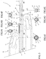
- la
figure 1 est une vue partielle en perspective d'une machine de fabrication selon l'invention montrant uniquement une partie du mandrin de formage longitudinal, les galets presseurs et les courroies de traction correspondants, - la
figure 2 est une vue en plan d'un mandrin de centrage suivi d'un mandrin provisoire situés en amont du mandrin de formage de la machine selon lafigure 1 , - la
figure 3 est une vue en plan du mandrin de formage de la machine selon lafigure 1 , - les
figures 4A à 4J sont des vues en coupe transversale des différents mandrins représentés auxfigures 2 et3 respectivement selon les plans A à J, - les
figures 5A et 5B sont des vues en coupe transversale d'un des galets presseurs respectivement avant et après appui contre le mandrin de formage, et - la
figure 6 est une vue de côté du galet presseur seul desfigures 5A et 5B .
- the
figure 1 is a partial perspective view of a manufacturing machine according to the invention showing only part of the longitudinal forming mandrel, the pressure rollers and the corresponding traction belts, - the
figure 2 is a plan view of a centering mandrel followed by a temporary mandrel located upstream of the forming mandrel of the machine according to thefigure 1 , - the
figure 3 is a plan view of the forming mandrel of the machine according to thefigure 1 , - the
Figures 4A to 4J are cross-sectional views of the different mandrels shown infigures 2 and3 respectively according to the plans A to J, - the
Figures 5A and 5B are cross-sectional views of one of the pressure rollers respectively before and after pressing against the forming mandrel, and - the
figure 6 is a side view of the presser roller aloneFigures 5A and 5B .
La machine 1 selon l'invention est illustrée partiellement dans les figures annexées pour ne montrer que les parties concernées par la présente invention, sans châssis ni carénage pour faciliter la compréhension. Cette machine permet la fabrication de corps tubulaires de boîtes, notamment à base de carton ou similaire, par exemple pour le conditionnement de produits alimentaires ou similaires, par déroulement dans le sens longitudinal d'une ou de plusieurs bandes de matière 2 enroulées en bobines, lesdites bandes étant encollées, superposées en nappe et légèrement décalées latéralement entre elles avant d'être appliquées contre un mandrin de formage 3 longitudinal autour duquel elles sont rabattues, pressées et laminées pour former un profilé tubulaire 4 fermé par un ou plusieurs joints longitudinaux 5 décalés. Ce profilé tubulaire 4 est ensuite tronçonné pour former lesdits corps tubulaires de boîtes aux dimensions voulues. Le joint longitudinal 5 est obtenu par collage des bords longitudinaux 6 superposés de chaque bande de matière 2, les bords longitudinaux de chaque bande de matière étant de préférence décalés latéralement pour que les joints longitudinaux desdites bandes de matière se chevauchent afin de ne pas fragiliser la paroi des corps tubulaires de boîtes dans cette zone de jonction. Si les corps tubulaires de boîtes sont réalisés à partir d'une seule bande de matière, alors il s'agit d'une bande de matière complexe ou composite, c'est-à-dire formée de plusieurs couches de matières différentes ou non en fonction des propriétés physiques que les corps tubulaires de boîtes doivent présenter.The
La machine 1 représentée partiellement dans les figures annexées comporte un mandrin de formage 3 longitudinal de section circulaire correspondant à la section intérieure des corps tubulaires de boîtes à fabriquer, qui sont par conséquent cylindriques. Bien entendu, cette machine 1 permet la fabrication de corps tubulaires de boîtes de toutes sections, telles que polygonales, ovoïdes ou autres.The
La machine 1 selon l'invention se distingue des machines connues par le fait que la fonction « laminage » des bandes de matière autour du mandrin de formage 3 et la fonction « traction » du profilé tubulaire formé lesdites bandes de matière sont dissociées et réalisées par des moyens de traction 10 et des moyens de pression 20 totalement distincts.The
Les moyens de traction 10 visibles sur les
Les moyens de pression 20 comportent une pluralité de galets presseurs 21 montés libres en rotation autour de leur axe, déformables et répartis radialement et longitudinalement autour du mandrin de formage 3 de manière à épouser parfaitement l'ensemble du périmètre de ce mandrin de formage 3 pour assurer un laminage uniforme et puissant de la nappe de bandes de matière 2 contre le mandrin de formage 3 favorisant leur cohésion et assemblage intime par collage.The pressure means 20 comprise a plurality of
Les
Lorsque le galet presseur 21 n'est pas mis sous pression contre le mandrin de formage 3, il définit un jeu J entre sa garniture 23 qui n'est pas contrainte et le profilé tubulaire 4 porté par le mandrin de formage 3 (voir
De plus, le galet presseur 21 est monté libre en rotation sur son axe et ne génère aucun frottement ni glissement sur le profilé tubulaire 4. Pour réduire voire supprimer les vitesses différentielles dans les zones d'extrémité du galet presseur 21, la dimension de ces galets presseurs 21 est réduite et leur nombre augmenté.In addition, the
Le fût 22 du galet presseur 21 est monté libre en rotation sur un axe 24 par des paliers 25 à billes ou similaires, lequel axe 24 est porté par un support 26. Ce support 26 comporte une platine 27 fixée sur le châssis (non représenté) de la machine 1 de manière à être démontable et réglable en position radiale par rapport au mandrin de formage 3, facilitant ainsi les opérations de maintenance et de réglage. Ce support 26 comporte un coulisseau 28 guidé en translation dans la platine 27 et à l'extrémité duquel est fixé ledit axe 24 portant le galet presseur 21. Ce coulisseau 28 est déplacé en translation radiale par rapport au mandrin de formage 3 au moyen d'un actionneur linéaire, tel un vérin (non représenté), permettant d'appliquer le galet presseur 21 contre le mandrin de formage 3 avec une pression définie et réglable. Ce coulisseau 28 comporte au moins deux colonnes de guidage 29, situées symétriquement par rapport à une tige centrale 30 prolongeant l'actionneur linéaire, les deux colonnes 29 et la tige centrale 30 étant agencées pour coulisser dans des alésages correspondants prévus dans la platine 27. Bien entendu, tout autre moyen équivalent de guidage et/ou de mise sous pression des galets presseurs 21 est envisageable.The
Dans l'exemple illustré, notamment aux
Un mandrin provisoire 41 longitudinal disposé en aval du mandrin de centrage 40 et en amont du mandrin de formage 3 peut être prévu lorsqu'il est nécessaire de souder un film barrière formant une membrane ou couche intérieure prévue dans les corps tubulaires de boîtes à fabriquer pour respecter des contraintes d'étanchéité. Pour faciliter cette opération et garantir une soudure de qualité optimale, ce mandrin provisoire 41 présente une section en forme de goutte d'eau dont le développé correspond au développé intérieur D des corps tubulaires de boîtes à fabriquer (
En sortie du mandrin provisoire 41 s'il existe ou dans la continuité du mandrin de centrage 40, et en amont du mandrin de formage 3, la nappe de bandes de matière 2 est rabattue latéralement par un galet de rabattage 43 offrant un profil complémentaire au demi-mandrin provisoire 41 ou au mandrin de centrage 40 (
Dans l'exemple représenté, les galets presseurs 21, 21' sont au nombre de huit :
-
figure 4E , un premier galet presseur 21 symétrique et centré sur la partie inférieure du mandrin de formage 3 laminant la nappe de bandes de matière 2 sur un premier secteur couvrant environ ¼ du périmètre du mandrin de formage 3, -
figure 4F , un deuxième et un troisième demi-galets presseurs 21' disposés symétriquement rabattant et laminant la nappe de bandes de matière 2 sur les deuxième et troisième secteurs latéraux inférieurs, couvrant chacunenviron 1/8e du périmètre du mandrin de formage 3, -
figure 4G , un quatrième et un cinquième demi-galets presseurs 21' disposés symétriquement rabattant et laminant la nappe de bandes de matière 2 sur les quatrième et cinquième secteurs latéraux médians, couvrant chacunenviron 1/8e du périmètre du mandrin de formage 3, -
figure 4H , un sixième et un septième demi-galets presseurs 21' disposés symétriquement rabattant et laminant la nappe de bandes de matière 2 sur les sixième et septièmes secteurs latéraux supérieurs, couvrant chacunenviron 1/8e du périmètre du mandrin de formage 3, et -
figure 4I , un huitième galet presseur 21, ou dans l'exemple représenté une série de cinq galets presseurs 21 alignés, symétriques et centrés sur la partie supérieure du mandrin de formage 3 laminant la zone de jonction des bords longitudinaux des bandes de matière 2 sur un huitième et dernier secteur couvrant environ ¼ du périmètre du mandrin de formage 3. La série de galets presseurs 21 favorise la qualité du scellage des bords longitudinaux entre eux.
-
figure 4E afirst pressure roller 21 symmetrical and centered on the lower part of the formingmandrel 3 rolling the web ofmaterial strips 2 on a first sector covering about ¼ of the perimeter of the formingmandrel 3, -
figure 4F a second and third press rollers 21 'symmetrically folding and laminating the web ofmaterial webs 2 on the second and third lower side sectors, each covering about 1/8 th of the perimeter of the formingmandrel 3, -
figure 4G a fourth and a fifth pressure rollers 21 'symmetrically folding and laminating the web ofmaterial webs 2 onto the fourth and fifth medial side sectors, each covering about 1/8 th of the perimeter of the formingmandrel 3, -
Figure 4H , a sixth and a seventh pressure-roller half-rollers 21 'arranged symmetrically folding and rolling the web of strips ofmaterial 2 on the sixth and seventh upper lateral sectors, each covering about 1/8 th of the perimeter of the formingmandrel 3, and -
figure 4I , aneighth pressure roller 21, or in the example shown a series of fivepressure rollers 21 aligned, symmetrical and centered on the upper part of the formingmandrel 3 rolling the junction area of the longitudinal edges of the material strips 2 on an eighth and last sector covering about ¼ of the perimeter of the formingmandrel 3. The series ofpressure rollers 21 promotes the quality of the sealing of the longitudinal edges between them.
Il ressort clairement de cette description que l'invention permet d'atteindre les buts fixés. Notamment, cette nouvelle conception permet de séquencer la fermeture des galets presseurs à la mise en route de la machine et ainsi d'automatiser le démarrage générant des gains importants. De même, les changements de format de corps tubulaires de boîtes à fabriquer sont plus rapides ainsi que les opérations de maintenance. De plus, les corps de boîtes ainsi fabriqués sont de meilleure qualité aussi bien au niveau résistance mécanique qu'au niveau des propriétés barrières.It is clear from this description that the invention achieves the goals. In particular, this new design makes it possible to sequence the closing of the pinch rollers at the start of the machine and thus to automate the start generating significant gains. Likewise, changes in the format of tubular bodies of boxes to be manufactured are faster as well as the maintenance operations. In addition, the box bodies thus manufactured are of better quality both in terms of mechanical strength and barrier properties.
La présente invention n'est pas limitée à l'exemple de réalisation décrit mais s'étend à toute modification et variante évidentes pour un homme du métier tout en restant dans l'étendue de la protection définie dans les revendications annexées.The present invention is not limited to the embodiment described but extends to any modification and variation obvious to a person skilled in the art while remaining within the scope of protection defined in the appended claims.
Claims (15)
- Machine (1) for the continuous manufacture of tubular box bodies, notably based on cardboard or the like, this machine comprising at least one longitudinal forming mandrel (3) whose cross-section corresponds to the internal cross-section of the tubular bodies of the boxes to be manufactured and around which at least one longitudinally unwound and previously at least partly glue-coated strip of material (2) is applied and folded in order to form a closed tubular profile (4), this machine comprising furthermore pressing means (20) arranged for rolling said at least one strip of material (2) against said forming mandrel (3), and traction means (10) arranged for moving continuously said tubular profile (4) along said forming mandrel (3), characterized in that said pressing means (20) and said traction means (10) are distinct and in that said pressing means (20) comprise a plurality of press rollers (21, 21') mounted free in rotation about their axis, said press rollers being deformable and radially distributed around said forming mandrel (3) so as to fit the periphery of said mandrel.
- Machine according to claim 1, characterized in that said press rollers (21, 21') are distributed symmetrically around said forming mandrel (3), each covering a sector of said mandrel, and are offset longitudinally so as to cover the whole periphery of said mandrel.
- Machine according to any of claims 1 and 2, characterized in that every press roller (21, 21') comprises a lining (23) made out of an elastic material.
- Machine according to claim 3, characterized in that the elastic lining (23) of every press roller (21, 21') has a profile complementary to that of the sector of said forming mandrel (3) against which the corresponding press roller is pressed.
- Machine according to claim 3, characterized in that said elastic lining (23) comprises internal recesses (23') arranged to increase its elasticity.
- Machine according to claim 3, characterized in that the elastic material of said lining is chosen in the group including the natural rubbers and the polyurethane-based synthetic rubbers.
- Machine according to claim 1, characterized in that each press roller (21, 21') is carried by a support (26) whose radial position is adjustable with respect to said forming mandrel (3).
- Machine according to claim 7, characterized in that each press roller (21, 21') is coupled with a pressurizing element carried by said support (26).
- Machine according to any of the previous claims, characterized in that it moreover comprises a longitudinal centering mandrel (40) arranged upstream of said forming mandrel (3) and having a polygonal cross-section whose development is smaller than the development of the internal cross-section of the tubular box bodies to be manufactured, said centering mandrel (40) being arranged to guide said strips of material (2) longitudinally and transversally without slipping.
- Machine according to claim 9, characterized in that it also comprises a temporary longitudinal mandrel (41) arranged downstream of said centering mandrel (40) and upstream of said forming mandrel (3) and having a water drop-shaped cross-section whose development corresponds to the development of the internal cross-section (D) of the tubular box bodies to be manufactured.
- Machine according to claim 10, characterized in that it comprises a welding station (42) adjacent to said temporary mandrel (41) to weld the longitudinal edges of at least one strip of material forming the internal layer of said tubular box bodies.
- Machine according to any of the previous claims, characterized in that it moreover comprises a series of press rollers (21) aligned on a longitudinal sector of said forming mandrel (3) corresponding to an area where the longitudinal edges of said at least one strip of material (2) meet to close said tubular profile (4) by means of at least one longitudinal joint.
- Machine according to any of the previous claims, characterized in that said traction means (10) comprise at least one traction belt (11) carried by drive rollers (12) and arranged downstream of said pressing means.
- Machine according to claim 13, characterized in that said traction means (10) comprise at least two traction belts (11) arranged symmetrically with respect to said forming mandrel (3).
- Machine according to any of the previous claims, characterized in that it comprises at least one gluing nozzle (44) arranged to add glue on at least some of the longitudinal edges of said strips of material (2).
Priority Applications (1)
| Application Number | Priority Date | Filing Date | Title |
|---|---|---|---|
| PL14727575T PL2988928T3 (en) | 2013-04-22 | 2014-04-09 | Machine for the continuous manufacture of tubular box bodies, notably based on cardboard or the like |
Applications Claiming Priority (2)
| Application Number | Priority Date | Filing Date | Title |
|---|---|---|---|
| FR1353638A FR3004671B1 (en) | 2013-04-22 | 2013-04-22 | MACHINE FOR THE CONTINUOUS MANUFACTURE OF TUBULAR BODIES OF BOXES, IN PARTICULAR CARDBOARD OR SIMILAR |
| PCT/FR2014/000082 WO2014174161A1 (en) | 2013-04-22 | 2014-04-09 | Machine for the continuous manufacture of tubular box bodies, notably based on cardboard or the like |
Publications (2)
| Publication Number | Publication Date |
|---|---|
| EP2988928A1 EP2988928A1 (en) | 2016-03-02 |
| EP2988928B1 true EP2988928B1 (en) | 2017-06-14 |
Family
ID=48656177
Family Applications (1)
| Application Number | Title | Priority Date | Filing Date |
|---|---|---|---|
| EP14727575.4A Active EP2988928B1 (en) | 2013-04-22 | 2014-04-09 | Machine for the continuous manufacture of tubular box bodies, notably based on cardboard or the like |
Country Status (10)
| Country | Link |
|---|---|
| US (1) | US20160082686A1 (en) |
| EP (1) | EP2988928B1 (en) |
| JP (1) | JP6425145B2 (en) |
| CA (1) | CA2911842A1 (en) |
| ES (1) | ES2639466T3 (en) |
| FR (1) | FR3004671B1 (en) |
| PL (1) | PL2988928T3 (en) |
| PT (1) | PT2988928T (en) |
| RU (1) | RU2649300C2 (en) |
| WO (1) | WO2014174161A1 (en) |
Families Citing this family (2)
| Publication number | Priority date | Publication date | Assignee | Title |
|---|---|---|---|---|
| IT201900009162A1 (en) | 2019-06-17 | 2020-12-17 | Engraving Solutions S R L | METHOD AND MACHINE FOR PRODUCING ROLLS OF RAPE MATERIAL WRAPPED ON TUBULAR CORE AND RELATED PRODUCT OBTAINED |
| IT202100008879A1 (en) * | 2021-04-09 | 2022-10-09 | Comec Srl | CONTINUOUS PLANT FOR THE FORMING OF A TUBULAR ELEMENT FROM A FLAT RIBBON OF PAPER MATERIAL AND RELATED METHOD |
Family Cites Families (35)
| Publication number | Priority date | Publication date | Assignee | Title |
|---|---|---|---|---|
| US3124872A (en) * | 1964-03-17 | Method and apparatus for severing a continuous | ||
| US3338142A (en) * | 1967-08-29 | Method and machine for making tubular container bodies | ||
| US1761980A (en) * | 1927-07-05 | 1930-06-03 | Bundy Tubing Co | Method of making finned tubing |
| US1983361A (en) * | 1933-10-27 | 1934-12-04 | Boothby Fibre Can Company | Container made of paper and method of producing it |
| US2016273A (en) * | 1934-09-14 | 1935-10-08 | Harry N Atwood | Built-up composite cellular structure |
| US2125758A (en) * | 1935-05-08 | 1938-08-02 | Harry F Waters | Machine for manufacturing bags |
| US2148884A (en) * | 1935-06-05 | 1939-02-28 | Ind Patents Corp | Method for forming synthetic sausage casings |
| US2256263A (en) * | 1940-10-10 | 1941-09-16 | Continental Can Co | Method of and apparatus for forming paper container bodies |
| US3623929A (en) * | 1966-10-07 | 1971-11-30 | Int Paper Co | Method for producing spiral wound container |
| US3908526A (en) * | 1971-07-08 | 1975-09-30 | Venizelos Vassalos | Machine and method to produce fiberboard tubes of polygonal cross-section |
| US4198739A (en) * | 1976-05-19 | 1980-04-22 | Rodel, Inc. | Printing roller with polymeric coner and method of making the same |
| DE2837184A1 (en) * | 1978-08-25 | 1980-03-06 | Kabel Metallwerke Ghh | METHOD AND DEVICE FOR PRODUCING TUBES FOR HEAT EXCHANGERS |
| US4528053A (en) * | 1982-09-29 | 1985-07-09 | Auer Mark J | Manufacturing fiberboard ducts |
| US4629529A (en) * | 1984-10-22 | 1986-12-16 | Steeltin Can Corporation | Method and machine for convolute or spiral winding of composite materials |
| JPH0452047Y2 (en) * | 1987-07-03 | 1992-12-08 | ||
| JPH0796262B2 (en) * | 1987-03-14 | 1995-10-18 | 北海製罐株式会社 | Method and apparatus for forming tubular body |
| JPS6457925A (en) * | 1987-08-28 | 1989-03-06 | Toshiba Corp | Production of spiral body |
| EP0312058B1 (en) * | 1987-10-14 | 1994-09-07 | Canon Kabushiki Kaisha | Image fixing roller and image fixing apparatus having same |
| JP2566444B2 (en) * | 1988-05-30 | 1996-12-25 | 北海製罐株式会社 | Method for molding composite tubular body |
| DE3915508A1 (en) * | 1989-05-12 | 1990-11-15 | Feldmuehle Ag | ROLLER FOR PRINTING TREATMENT OF TRACKS |
| GB9201096D0 (en) * | 1992-01-20 | 1992-03-11 | Unilever Plc | Tube-forming apparatus |
| FR2702414B1 (en) | 1993-03-12 | 1996-07-05 | Helverep Sa | Process for the continuous production of tubular bodies of boxes, in particular of cardboard. |
| SE9503560D0 (en) * | 1995-10-11 | 1995-10-11 | Ingmar Andreasson | Pallet |
| AUPO221796A0 (en) * | 1996-09-09 | 1996-10-03 | Acworth, Arthur Keith | Improvements to weights and sinkers |
| US5829669A (en) * | 1997-02-06 | 1998-11-03 | Sonoco Products Company | Tubular container and methods and apparatus for manufacturing same |
| US5707329A (en) * | 1997-02-11 | 1998-01-13 | Pool; George H. | Narrow profile apparatus for forming tubes from plastic web stock |
| FR2763888B1 (en) * | 1997-05-28 | 1999-07-16 | Rollin Sa | IMPROVED SLEEVE FOR A CYLINDER OF A PRINTING MACHINE OR THE LIKE AND METHOD FOR FITTING THEREOF |
| ES1049406Y (en) * | 2001-06-15 | 2002-04-16 | Roca Ramon Valls | CARTON TUBE FOR THREADS. |
| DE10261983A1 (en) * | 2002-09-21 | 2004-04-08 | Koenig & Bauer Ag | Method for adjusting the contact pressure of an adjustable roller |
| US20040121891A1 (en) * | 2002-12-19 | 2004-06-24 | Sonoco Development, Inc. | Stage cut patterns for linear drawn composite containers |
| FI117280B (en) * | 2003-01-10 | 2006-08-31 | Metso Paper Inc | Method of conveyor and conveyor |
| US20070125474A1 (en) * | 2005-12-05 | 2007-06-07 | Huber Engineered Woods L.L.C. | Handheld tape applicator and components thereof, and their methods of use |
| US8167782B2 (en) * | 2007-02-16 | 2012-05-01 | Linzer Products Corp. | Method and apparatus for making a paint roller and product produced thereby |
| JP6041623B2 (en) * | 2012-10-29 | 2016-12-14 | キヤノン株式会社 | Fixing member and manufacturing method thereof |
| CN105799217A (en) * | 2016-03-16 | 2016-07-27 | 稳健医疗用品股份有限公司 | Non-woven fabric environment-friendly bag manufacturing method and equipment |
-
2013
- 2013-04-22 FR FR1353638A patent/FR3004671B1/en active Active
-
2014
- 2014-04-09 RU RU2015149765A patent/RU2649300C2/en active
- 2014-04-09 PT PT147275754T patent/PT2988928T/en unknown
- 2014-04-09 PL PL14727575T patent/PL2988928T3/en unknown
- 2014-04-09 ES ES14727575.4T patent/ES2639466T3/en active Active
- 2014-04-09 CA CA2911842A patent/CA2911842A1/en not_active Abandoned
- 2014-04-09 JP JP2016508205A patent/JP6425145B2/en active Active
- 2014-04-09 WO PCT/FR2014/000082 patent/WO2014174161A1/en active Application Filing
- 2014-04-09 EP EP14727575.4A patent/EP2988928B1/en active Active
- 2014-04-09 US US14/785,444 patent/US20160082686A1/en not_active Abandoned
Non-Patent Citations (1)
| Title |
|---|
| None * |
Also Published As
| Publication number | Publication date |
|---|---|
| FR3004671B1 (en) | 2015-05-22 |
| PT2988928T (en) | 2017-09-12 |
| RU2649300C2 (en) | 2018-03-30 |
| RU2015149765A (en) | 2017-05-26 |
| JP6425145B2 (en) | 2018-11-21 |
| PL2988928T3 (en) | 2017-12-29 |
| CA2911842A1 (en) | 2014-10-30 |
| US20160082686A1 (en) | 2016-03-24 |
| FR3004671A1 (en) | 2014-10-24 |
| JP2016516614A (en) | 2016-06-09 |
| ES2639466T3 (en) | 2017-10-26 |
| WO2014174161A1 (en) | 2014-10-30 |
| EP2988928A1 (en) | 2016-03-02 |
Similar Documents
| Publication | Publication Date | Title |
|---|---|---|
| EP2782840B1 (en) | Device for closing pouches with tactile and sound features and pouch comprising such a device | |
| EP0300855B1 (en) | Web with longitudinal reinforcement, its manufacture and its use in packaging methods and device for making such a web | |
| EP1679265A1 (en) | Tube with non-circular cross-section, its manufacturing method and apparatus therefor | |
| EP2988928B1 (en) | Machine for the continuous manufacture of tubular box bodies, notably based on cardboard or the like | |
| FR2702414A1 (en) | Process for the continuous manufacture of tubular bodies of boxes, especially cardboard boxes | |
| EP2188110B1 (en) | Method for manufacturing tubes by welding | |
| FR2756339A1 (en) | EXPANDABLE SHAFT FOR BAND WINDING APPARATUS | |
| WO2017144801A1 (en) | Device for applying abradable material to a surface of a turbomachine casing | |
| EP2613929B1 (en) | Method for producing a raw tyre blank, comprising a stitching step | |
| EP1565303B1 (en) | Method for making plastic or metalloplastic flexible tubes | |
| EP2145755A1 (en) | Method for forming profiles with an angular section and device for implementing this method | |
| EP2511567B1 (en) | Method for manufacturing a strip of material in a loop | |
| FR2876365A1 (en) | METHOD AND APPARATUS FOR COIL WINDING OF A BAND | |
| EP0038277A1 (en) | Machine for forming a tubular profile | |
| FR2846954A1 (en) | Paper roll forming procedure includes unrolling, folding and rewinding operations to produce one or more rolls | |
| EP2254746B1 (en) | Method and device for making a reinforcement by winding a tape on itself | |
| FR2628029A1 (en) | DEVICE FOR DRAWING A FILM OF PLASTIC MATERIAL | |
| FR2688738A1 (en) | Method for manufacturing one or more profiled sections made from flexible material, particularly from paper, cardboard, composite materials or the like, and device for implementing this method | |
| FR2629562A1 (en) | METHOD AND DEVICE FOR COATING WELDED TUBES | |
| BE1006210A6 (en) | Separation sheets meetings with film continue. | |
| WO2021084191A1 (en) | Method and device for manufacturing a conical filter | |
| EP0921938A1 (en) | Machine and method for making a sheet of single-face corrugated paperboard using traction feed prior to rolls | |
| CA2260260A1 (en) | Rigid corrugated cardboard | |
| FR2974820A1 (en) | ROLL FOR SEAL HEAD AND METHOD OF MANUFACTURE | |
| CH312220A (en) | Apparatus for pre-folding cardboard blanks. |
Legal Events
| Date | Code | Title | Description |
|---|---|---|---|
| PUAI | Public reference made under article 153(3) epc to a published international application that has entered the european phase |
Free format text: ORIGINAL CODE: 0009012 |
|
| 17P | Request for examination filed |
Effective date: 20151019 |
|
| AK | Designated contracting states |
Kind code of ref document: A1 Designated state(s): AL AT BE BG CH CY CZ DE DK EE ES FI FR GB GR HR HU IE IS IT LI LT LU LV MC MK MT NL NO PL PT RO RS SE SI SK SM TR |
|
| AX | Request for extension of the european patent |
Extension state: BA ME |
|
| DAX | Request for extension of the european patent (deleted) | ||
| GRAP | Despatch of communication of intention to grant a patent |
Free format text: ORIGINAL CODE: EPIDOSNIGR1 |
|
| INTG | Intention to grant announced |
Effective date: 20170119 |
|
| RIC1 | Information provided on ipc code assigned before grant |
Ipc: B31F 7/00 20060101ALI20170117BHEP Ipc: B31B 50/28 20170101ALI20170117BHEP Ipc: B31F 1/00 20060101AFI20170117BHEP |
|
| GRAJ | Information related to disapproval of communication of intention to grant by the applicant or resumption of examination proceedings by the epo deleted |
Free format text: ORIGINAL CODE: EPIDOSDIGR1 |
|
| GRAJ | Information related to disapproval of communication of intention to grant by the applicant or resumption of examination proceedings by the epo deleted |
Free format text: ORIGINAL CODE: EPIDOSDIGR1 |
|
| GRAP | Despatch of communication of intention to grant a patent |
Free format text: ORIGINAL CODE: EPIDOSNIGR1 |
|
| GRAS | Grant fee paid |
Free format text: ORIGINAL CODE: EPIDOSNIGR3 |
|
| INTC | Intention to grant announced (deleted) | ||
| GRAR | Information related to intention to grant a patent recorded |
Free format text: ORIGINAL CODE: EPIDOSNIGR71 |
|
| GRAS | Grant fee paid |
Free format text: ORIGINAL CODE: EPIDOSNIGR3 |
|
| GRAA | (expected) grant |
Free format text: ORIGINAL CODE: 0009210 |
|
| INTG | Intention to grant announced |
Effective date: 20170504 |
|
| AK | Designated contracting states |
Kind code of ref document: B1 Designated state(s): AL AT BE BG CH CY CZ DE DK EE ES FI FR GB GR HR HU IE IS IT LI LT LU LV MC MK MT NL NO PL PT RO RS SE SI SK SM TR |
|
| REG | Reference to a national code |
Ref country code: GB Ref legal event code: FG4D Free format text: NOT ENGLISH |
|
| REG | Reference to a national code |
Ref country code: CH Ref legal event code: EP Ref country code: AT Ref legal event code: REF Ref document number: 900550 Country of ref document: AT Kind code of ref document: T Effective date: 20170615 |
|
| REG | Reference to a national code |
Ref country code: IE Ref legal event code: FG4D Free format text: LANGUAGE OF EP DOCUMENT: FRENCH |
|
| REG | Reference to a national code |
Ref country code: DE Ref legal event code: R096 Ref document number: 602014010787 Country of ref document: DE |
|
| REG | Reference to a national code |
Ref country code: CH Ref legal event code: NV Representative=s name: CABINET ROLAND NITHARDT CONSEILS EN PROPRIETE , CH |
|
| REG | Reference to a national code |
Ref country code: PT Ref legal event code: SC4A Ref document number: 2988928 Country of ref document: PT Date of ref document: 20170912 Kind code of ref document: T Free format text: AVAILABILITY OF NATIONAL TRANSLATION Effective date: 20170901 |
|
| REG | Reference to a national code |
Ref country code: NL Ref legal event code: FP |
|
| REG | Reference to a national code |
Ref country code: LT Ref legal event code: MG4D |
|
| REG | Reference to a national code |
Ref country code: ES Ref legal event code: FG2A Ref document number: 2639466 Country of ref document: ES Kind code of ref document: T3 Effective date: 20171026 |
|
| PG25 | Lapsed in a contracting state [announced via postgrant information from national office to epo] |
Ref country code: GR Free format text: LAPSE BECAUSE OF FAILURE TO SUBMIT A TRANSLATION OF THE DESCRIPTION OR TO PAY THE FEE WITHIN THE PRESCRIBED TIME-LIMIT Effective date: 20170915 Ref country code: FI Free format text: LAPSE BECAUSE OF FAILURE TO SUBMIT A TRANSLATION OF THE DESCRIPTION OR TO PAY THE FEE WITHIN THE PRESCRIBED TIME-LIMIT Effective date: 20170614 Ref country code: LT Free format text: LAPSE BECAUSE OF FAILURE TO SUBMIT A TRANSLATION OF THE DESCRIPTION OR TO PAY THE FEE WITHIN THE PRESCRIBED TIME-LIMIT Effective date: 20170614 Ref country code: HR Free format text: LAPSE BECAUSE OF FAILURE TO SUBMIT A TRANSLATION OF THE DESCRIPTION OR TO PAY THE FEE WITHIN THE PRESCRIBED TIME-LIMIT Effective date: 20170614 Ref country code: NO Free format text: LAPSE BECAUSE OF FAILURE TO SUBMIT A TRANSLATION OF THE DESCRIPTION OR TO PAY THE FEE WITHIN THE PRESCRIBED TIME-LIMIT Effective date: 20170914 |
|
| REG | Reference to a national code |
Ref country code: AT Ref legal event code: MK05 Ref document number: 900550 Country of ref document: AT Kind code of ref document: T Effective date: 20170614 |
|
| PG25 | Lapsed in a contracting state [announced via postgrant information from national office to epo] |
Ref country code: SE Free format text: LAPSE BECAUSE OF FAILURE TO SUBMIT A TRANSLATION OF THE DESCRIPTION OR TO PAY THE FEE WITHIN THE PRESCRIBED TIME-LIMIT Effective date: 20170614 Ref country code: RS Free format text: LAPSE BECAUSE OF FAILURE TO SUBMIT A TRANSLATION OF THE DESCRIPTION OR TO PAY THE FEE WITHIN THE PRESCRIBED TIME-LIMIT Effective date: 20170614 Ref country code: LV Free format text: LAPSE BECAUSE OF FAILURE TO SUBMIT A TRANSLATION OF THE DESCRIPTION OR TO PAY THE FEE WITHIN THE PRESCRIBED TIME-LIMIT Effective date: 20170614 Ref country code: BG Free format text: LAPSE BECAUSE OF FAILURE TO SUBMIT A TRANSLATION OF THE DESCRIPTION OR TO PAY THE FEE WITHIN THE PRESCRIBED TIME-LIMIT Effective date: 20170914 |
|
| PG25 | Lapsed in a contracting state [announced via postgrant information from national office to epo] |
Ref country code: RO Free format text: LAPSE BECAUSE OF FAILURE TO SUBMIT A TRANSLATION OF THE DESCRIPTION OR TO PAY THE FEE WITHIN THE PRESCRIBED TIME-LIMIT Effective date: 20170614 Ref country code: CZ Free format text: LAPSE BECAUSE OF FAILURE TO SUBMIT A TRANSLATION OF THE DESCRIPTION OR TO PAY THE FEE WITHIN THE PRESCRIBED TIME-LIMIT Effective date: 20170614 Ref country code: SK Free format text: LAPSE BECAUSE OF FAILURE TO SUBMIT A TRANSLATION OF THE DESCRIPTION OR TO PAY THE FEE WITHIN THE PRESCRIBED TIME-LIMIT Effective date: 20170614 Ref country code: EE Free format text: LAPSE BECAUSE OF FAILURE TO SUBMIT A TRANSLATION OF THE DESCRIPTION OR TO PAY THE FEE WITHIN THE PRESCRIBED TIME-LIMIT Effective date: 20170614 Ref country code: AT Free format text: LAPSE BECAUSE OF FAILURE TO SUBMIT A TRANSLATION OF THE DESCRIPTION OR TO PAY THE FEE WITHIN THE PRESCRIBED TIME-LIMIT Effective date: 20170614 |
|
| PG25 | Lapsed in a contracting state [announced via postgrant information from national office to epo] |
Ref country code: IS Free format text: LAPSE BECAUSE OF FAILURE TO SUBMIT A TRANSLATION OF THE DESCRIPTION OR TO PAY THE FEE WITHIN THE PRESCRIBED TIME-LIMIT Effective date: 20171014 Ref country code: SM Free format text: LAPSE BECAUSE OF FAILURE TO SUBMIT A TRANSLATION OF THE DESCRIPTION OR TO PAY THE FEE WITHIN THE PRESCRIBED TIME-LIMIT Effective date: 20170614 |
|
| REG | Reference to a national code |
Ref country code: DE Ref legal event code: R097 Ref document number: 602014010787 Country of ref document: DE |
|
| PLBE | No opposition filed within time limit |
Free format text: ORIGINAL CODE: 0009261 |
|
| STAA | Information on the status of an ep patent application or granted ep patent |
Free format text: STATUS: NO OPPOSITION FILED WITHIN TIME LIMIT |
|
| REG | Reference to a national code |
Ref country code: FR Ref legal event code: PLFP Year of fee payment: 5 |
|
| PG25 | Lapsed in a contracting state [announced via postgrant information from national office to epo] |
Ref country code: DK Free format text: LAPSE BECAUSE OF FAILURE TO SUBMIT A TRANSLATION OF THE DESCRIPTION OR TO PAY THE FEE WITHIN THE PRESCRIBED TIME-LIMIT Effective date: 20170614 |
|
| 26N | No opposition filed |
Effective date: 20180315 |
|
| PG25 | Lapsed in a contracting state [announced via postgrant information from national office to epo] |
Ref country code: SI Free format text: LAPSE BECAUSE OF FAILURE TO SUBMIT A TRANSLATION OF THE DESCRIPTION OR TO PAY THE FEE WITHIN THE PRESCRIBED TIME-LIMIT Effective date: 20170614 |
|
| PG25 | Lapsed in a contracting state [announced via postgrant information from national office to epo] |
Ref country code: MT Free format text: LAPSE BECAUSE OF FAILURE TO SUBMIT A TRANSLATION OF THE DESCRIPTION OR TO PAY THE FEE WITHIN THE PRESCRIBED TIME-LIMIT Effective date: 20170614 |
|
| PG25 | Lapsed in a contracting state [announced via postgrant information from national office to epo] |
Ref country code: MC Free format text: LAPSE BECAUSE OF FAILURE TO SUBMIT A TRANSLATION OF THE DESCRIPTION OR TO PAY THE FEE WITHIN THE PRESCRIBED TIME-LIMIT Effective date: 20170614 |
|
| REG | Reference to a national code |
Ref country code: IE Ref legal event code: MM4A |
|
| PG25 | Lapsed in a contracting state [announced via postgrant information from national office to epo] |
Ref country code: LU Free format text: LAPSE BECAUSE OF NON-PAYMENT OF DUE FEES Effective date: 20180409 |
|
| PG25 | Lapsed in a contracting state [announced via postgrant information from national office to epo] |
Ref country code: IE Free format text: LAPSE BECAUSE OF NON-PAYMENT OF DUE FEES Effective date: 20180409 |
|
| PG25 | Lapsed in a contracting state [announced via postgrant information from national office to epo] |
Ref country code: CY Free format text: LAPSE BECAUSE OF FAILURE TO SUBMIT A TRANSLATION OF THE DESCRIPTION OR TO PAY THE FEE WITHIN THE PRESCRIBED TIME-LIMIT Effective date: 20170614 Ref country code: HU Free format text: LAPSE BECAUSE OF FAILURE TO SUBMIT A TRANSLATION OF THE DESCRIPTION OR TO PAY THE FEE WITHIN THE PRESCRIBED TIME-LIMIT; INVALID AB INITIO Effective date: 20140409 Ref country code: MK Free format text: LAPSE BECAUSE OF NON-PAYMENT OF DUE FEES Effective date: 20170614 |
|
| PG25 | Lapsed in a contracting state [announced via postgrant information from national office to epo] |
Ref country code: AL Free format text: LAPSE BECAUSE OF FAILURE TO SUBMIT A TRANSLATION OF THE DESCRIPTION OR TO PAY THE FEE WITHIN THE PRESCRIBED TIME-LIMIT Effective date: 20170614 |
|
| PGFP | Annual fee paid to national office [announced via postgrant information from national office to epo] |
Ref country code: PT Payment date: 20210316 Year of fee payment: 8 |
|
| PGFP | Annual fee paid to national office [announced via postgrant information from national office to epo] |
Ref country code: TR Payment date: 20210330 Year of fee payment: 8 Ref country code: PL Payment date: 20210322 Year of fee payment: 8 |
|
| PG25 | Lapsed in a contracting state [announced via postgrant information from national office to epo] |
Ref country code: PT Free format text: LAPSE BECAUSE OF NON-PAYMENT OF DUE FEES Effective date: 20221010 |
|
| PGFP | Annual fee paid to national office [announced via postgrant information from national office to epo] |
Ref country code: NL Payment date: 20230327 Year of fee payment: 10 |
|
| PGFP | Annual fee paid to national office [announced via postgrant information from national office to epo] |
Ref country code: IT Payment date: 20230417 Year of fee payment: 10 Ref country code: FR Payment date: 20230427 Year of fee payment: 10 Ref country code: ES Payment date: 20230504 Year of fee payment: 10 Ref country code: DE Payment date: 20230412 Year of fee payment: 10 Ref country code: CH Payment date: 20230502 Year of fee payment: 10 |
|
| PG25 | Lapsed in a contracting state [announced via postgrant information from national office to epo] |
Ref country code: PL Free format text: LAPSE BECAUSE OF NON-PAYMENT OF DUE FEES Effective date: 20220409 |
|
| PGFP | Annual fee paid to national office [announced via postgrant information from national office to epo] |
Ref country code: BE Payment date: 20230424 Year of fee payment: 10 |
|
| PGFP | Annual fee paid to national office [announced via postgrant information from national office to epo] |
Ref country code: GB Payment date: 20230424 Year of fee payment: 10 |
|
| PGFP | Annual fee paid to national office [announced via postgrant information from national office to epo] |
Ref country code: NL Payment date: 20240325 Year of fee payment: 11 |