EP2983841B1 - Vorrichtung zum führen von langgestrecktem metallischem gut zwischen einer gutablaufeinrichtung und einem verbraucher - Google Patents
Vorrichtung zum führen von langgestrecktem metallischem gut zwischen einer gutablaufeinrichtung und einem verbraucher Download PDFInfo
- Publication number
- EP2983841B1 EP2983841B1 EP14709168.0A EP14709168A EP2983841B1 EP 2983841 B1 EP2983841 B1 EP 2983841B1 EP 14709168 A EP14709168 A EP 14709168A EP 2983841 B1 EP2983841 B1 EP 2983841B1
- Authority
- EP
- European Patent Office
- Prior art keywords
- product
- installation
- consumer
- run
- slide
- Prior art date
- Legal status (The legal status is an assumption and is not a legal conclusion. Google has not performed a legal analysis and makes no representation as to the accuracy of the status listed.)
- Not-in-force
Links
Images


Classifications
-
- B—PERFORMING OPERATIONS; TRANSPORTING
- B21—MECHANICAL METAL-WORKING WITHOUT ESSENTIALLY REMOVING MATERIAL; PUNCHING METAL
- B21C—MANUFACTURE OF METAL SHEETS, WIRE, RODS, TUBES, PROFILES OR LIKE SEMI-MANUFACTURED PRODUCTS OTHERWISE THAN BY ROLLING; AUXILIARY OPERATIONS USED IN CONNECTION WITH METAL-WORKING WITHOUT ESSENTIALLY REMOVING MATERIAL
- B21C47/00—Winding-up, coiling or winding-off metal wire, metal band or other flexible metal material characterised by features relevant to metal processing only
- B21C47/003—Regulation of tension or speed; Braking
-
- B—PERFORMING OPERATIONS; TRANSPORTING
- B21—MECHANICAL METAL-WORKING WITHOUT ESSENTIALLY REMOVING MATERIAL; PUNCHING METAL
- B21C—MANUFACTURE OF METAL SHEETS, WIRE, RODS, TUBES, PROFILES OR LIKE SEMI-MANUFACTURED PRODUCTS OTHERWISE THAN BY ROLLING; AUXILIARY OPERATIONS USED IN CONNECTION WITH METAL-WORKING WITHOUT ESSENTIALLY REMOVING MATERIAL
- B21C47/00—Winding-up, coiling or winding-off metal wire, metal band or other flexible metal material characterised by features relevant to metal processing only
- B21C47/16—Unwinding or uncoiling
- B21C47/18—Unwinding or uncoiling from reels or drums
-
- B—PERFORMING OPERATIONS; TRANSPORTING
- B21—MECHANICAL METAL-WORKING WITHOUT ESSENTIALLY REMOVING MATERIAL; PUNCHING METAL
- B21C—MANUFACTURE OF METAL SHEETS, WIRE, RODS, TUBES, PROFILES OR LIKE SEMI-MANUFACTURED PRODUCTS OTHERWISE THAN BY ROLLING; AUXILIARY OPERATIONS USED IN CONNECTION WITH METAL-WORKING WITHOUT ESSENTIALLY REMOVING MATERIAL
- B21C47/00—Winding-up, coiling or winding-off metal wire, metal band or other flexible metal material characterised by features relevant to metal processing only
- B21C47/34—Feeding or guiding devices not specially adapted to a particular type of apparatus
- B21C47/345—Feeding or guiding devices not specially adapted to a particular type of apparatus for monitoring the tension or advance of the material
-
- B—PERFORMING OPERATIONS; TRANSPORTING
- B21—MECHANICAL METAL-WORKING WITHOUT ESSENTIALLY REMOVING MATERIAL; PUNCHING METAL
- B21F—WORKING OR PROCESSING OF METAL WIRE
- B21F23/00—Feeding wire in wire-working machines or apparatus
-
- B—PERFORMING OPERATIONS; TRANSPORTING
- B65—CONVEYING; PACKING; STORING; HANDLING THIN OR FILAMENTARY MATERIAL
- B65H—HANDLING THIN OR FILAMENTARY MATERIAL, e.g. SHEETS, WEBS, CABLES
- B65H59/00—Adjusting or controlling tension in filamentary material, e.g. for preventing snarling; Applications of tension indicators
- B65H59/10—Adjusting or controlling tension in filamentary material, e.g. for preventing snarling; Applications of tension indicators by devices acting on running material and not associated with supply or take-up devices
- B65H59/36—Floating elements compensating for irregularities in supply or take-up of material
-
- B—PERFORMING OPERATIONS; TRANSPORTING
- B65—CONVEYING; PACKING; STORING; HANDLING THIN OR FILAMENTARY MATERIAL
- B65H—HANDLING THIN OR FILAMENTARY MATERIAL, e.g. SHEETS, WEBS, CABLES
- B65H2701/00—Handled material; Storage means
- B65H2701/30—Handled filamentary material
- B65H2701/36—Wires
Definitions
- the invention relates to a device for guiding elongate metallic material, such as wire, between a Gutablauf issued to a good of this subtractive consumer, in particular a wire bending machine, with a frame for holding a movable relative to the consumer Gutablinate listening.
- a device according to the preamble of claim 1 is for example from the FR-A-76 15180 known.
- wire drainage devices have to detach the wire from a standing wire bundle on a pendulum, which is rotatably mounted near the ground.
- a spring element is additionally attached, which brings the pendulum back to its original position.
- a roller block or a deflection arc At the upper end of the pendulum is a roller block or a deflection arc, in which the wire is guided, which is subtracted from the consumer of the wire bundle.
- This arrangement has the disadvantage that both the available wire storage and the sensitivity of the pendulum are dependent on the height of the withdrawal point.
- a relatively large mass inertia must be accelerated thereby with high wire coils. This has a negative effect on the wire waistband, which is thus repeatedly tied together, and on the wire itself, which is partially deformed, which subsequently can adversely affect the straightening quality.
- the invention aims to avoid the disadvantages described and to provide a device of the type described in the introduction, with a trouble-free controlled management of the goods and a compensation of the good may optionally jerkily applied withdrawal force can be achieved.
- the device according to the invention is characterized in that the material removal device is coupled with a retaining element, which is preferably formed from one or more springs or hydraulic cylinders, via a rotary element which is provided with a shaft to which a cam is fastened, its shape a linear characteristic of the retaining element generates a non-linear characteristic for a linearly movable slide the Gutablinate listening, which is connected to the retaining element by means of a cable which is guided over the cam and a shaft mounted on the disc.
- a retaining element which is preferably formed from one or more springs or hydraulic cylinders
- a sensor is attached to the shaft, via which the speed of the goods discharge device can be regulated by means of a control device and / or the production speed of the consumer can be influenced.
- the characteristic of the retaining element based on the Gutablinate raised, modifiable by displaceable on the shaft elements and thus the Gut barnmesser adaptable.
- the height and inclination of the material removal device can be continuously adjusted and adapted to the flow behavior of the material.
- the height and inclination of Gutablinate appeared be adjustable and suitable for Gutablauf esters with horizontal axis.
- a Gut is pivotally mounted on a carriage of Gutablinate addressed, preferably while maintaining a 30 ° Gutschleife on a horizontal support of a frame is slidably guided between the carriage work area defining end stops.
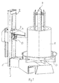
- Fig. 1 a wire guide device according to the invention
- Fig. 2 a schematic side view
- Fig. 3 a partial perspective view of the device
- Fig. 4 a force-displacement diagram.
- wire guide device shown generally has a wire harness B supporting wire drainage device I, which can be designed both motorized and braked configured, and a Drahtzugaustechnischs worn II and a consumer, not shown, which may be, for example, a wire straightener or a wire bending machine. Subsequently, the goods to be processed, which in Fig. 1 only indicated, referred to as wire D. However, the device according to the invention can also be used in conjunction with any other elongate profile material.
- the wire guide device is provided with a column 2 'of a frame 2, which is connected to the wire draining device I.
- a horizontal support 3 is fixed, which is also the roadway for a carriage 4, on which a roller block 5 is mounted, with the aid of the wire D is detached from the federal government B.
- the support 3 is continuously adjustable on the column 2 'in height and can thus be adjusted to the optimum trigger height. Likewise, the roller block 5 can be rotated in its inclination relative to the carriage 4.
- Fig. 3 shows a rope 6 attached, which runs over a cam 7, which is mounted on a shaft 8. The rope end is clamped at the beginning of the cam.
- a further cable 9 is attached to a pulley 11. The other end of the rope 9 is held by a retaining spring 10.
- the characteristic of the spring 10 Due to the shape of the cam 7, the characteristic of the spring 10, based on the travel of the carriage 4, be designed for any desired progression, such as Fig. 4 shows to create a damping effect for the carriage movement. Likewise, by adding spacers 11, which are cylindrical or cam-shaped, the characteristic of the spring 10 can be modified without disassembly of components according to the requirements of the goods.
- the wire guide device forms together with the wire draining device I a memory that compensates for unevenness in the production speed of the consumer. Increases material consumption in the short term, the carriage 4 exerts disproportionately to the linearly decreasing memory of a force on the wire coil B, which accelerates its rotation, so again more material is provided. If the carriage 4 exceeds a defined point because, for example, a disruption has occurred at the wire discharge device I, it is possible to switch off the consumer.
- the wire draining device I on which the wire harness B is placed, can either with a braked turntable 13, but also be designed with a motor-driven turntable. Via the optionally available sensor 12, it is possible to influence the speed of the wire draining device I as well as the production speed via the machine control. Likewise, it is possible to turn off the load when the memory has reached a defined minimum.
- the wire tension compensation device II which compensates for jerky pull-off forces occurring in the operation of the consumer, is suitable for all types of materials which can be placed on the wire draining device I, such as e.g. Compact coils, wild reeled wire coils, coils etc.
Landscapes
- Engineering & Computer Science (AREA)
- Mechanical Engineering (AREA)
- Coiling Of Filamentary Materials In General (AREA)
- Wire Processing (AREA)
- Winding, Rewinding, Material Storage Devices (AREA)
Description
- Die Erfindung betrifft eine Vorrichtung zum Führen von langgestrecktem metallischem Gut, wie Draht, zwischen einer Gutablaufeinrichtung zu einem das Gut von dieser abziehenden Verbraucher, insbesondere einer Drahtbiegemaschine, mit einem Gestell zur Halterung einer relativ zu dem Verbraucher bewegbaren Gutablöseeinrichtung.
- Eine Vorrichtung gemäß dem Oberbegriff des Anspruchs 1 ist z.B. aus der
FR-A-76 15180 - Derzeit auf dem Markt erhältliche Drahtablaufeinrichtungen weisen zur Ablöse des Drahtes von einem stehenden Drahtbund ein Pendel auf, welches in Bodennähe drehbar gelagert ist. Am Pendel ist zusätzlich ein Federelement befestigt, welches das Pendel in seine Ausgangsstellung zurück bringt. Am oberen Ende des Pendels befindet sich ein Rollenblock oder ein Umlenkbogen, in dem der Draht geführt wird, der vom Verbraucher von dem Drahtbund abgezogen wird. Diese Anordnung hat den Nachteil, dass sowohl der zur Verfügung stehende Drahtspeicher als auch die Sensibilität des Pendels von der Höhe des Abzugspunktes abhängig sind. Des Weiteren muss damit bei hohen Drahtbunden eine verhältnismäßig große Massenträgheit beschleunigt werden. Dies wirkt sich negativ auf den Drahtbund aus, der dadurch immer wieder zusammengeschnürt wird, und auf den Draht selbst, der teilweise deformiert wird, wodurch in weiterer Folge die Richtqualität negativ beeinflusst werden kann.
- Die Erfindung zielt darauf ab, die geschilderten Nachteile zu vermeiden und eine Vorrichtung der einleitend angegebenen Art zu schaffen, mit der eine störungsfreie gesteuerte Führung des Gutes sowie ein Ausgleich der auf das Gut gegebenenfalls ruckweise aufgebrachten Abzugskraft erzielt werden kann.
- Die erfindungsgemäße Vorrichtung zeichnet sich dadurch aus, dass die Gutablöseeinrichtung mit einem Rückhalteelement, das vorzugsweise aus einer oder mehreren Federn oder Hydraulikzylindern gebildet ist, über ein Drehelement gekoppelt ist, das mit einer Welle versehen ist, an der eine Nocke befestigt ist, deren Form aus einer linearen Kennlinie des Rückhalteelementes eine nicht lineare Kennlinie für einen linear bewegbaren Schlitten der Gutablöseeinrichtung erzeugt, der mit dem Rückhalteelement mittels eines Seilzuges verbunden ist, der über die Nocke und über eine an der Welle gelagerte Scheibe geführt ist.
- Nach einem weiteren Erfindungsmerkmal ist an der Welle ein Sensor befestigt, über den die Drehzahl der Gutablaufeinrichtung mittels einer Steuereinrichtung regelbar und/oder die Produktionsgeschwindigkeit des Verbrauchers beeinflussbar ist.
- Vorzugsweise ist die Kennlinie des Rückhalteelementes, bezogen auf die Gutablöseeinrichtung, durch auf der Welle verschiebbare Elemente modifizierbar und somit dem Gutdurchmesser anpassbar.
- Erfindungsgemäß kann die Höhe und Neigung der Gutablöseeinrichtung stufenlos verstellbar und an das Ablaufverhalten des Gutes anpassbar sein.
- Alternativ kann im Rahmen der Erfindung die Höhe und Neigung der Gutablöseeinrichtung verstellbar und auch für Gutablaufeinrichtungen mit horizontaler Achse geeignet sein.
- Bei einer praktischen Ausführungsform der Erfindung ist vorgesehen, dass eine Gutführungsrolle schwenkbeweglich an einem Schlitten der Gutablöseeinrichtung montiert ist, der vorzugsweise unter Aufrechterhaltung einer 30° Gutschleife an einem horizontalen Träger eines Gestells gleitverschieblich zwischen den Schlitten-Arbeitsbereich definierenden Endanschlägen geführt ist.
- Weitere Merkmale der Erfindung werden nachfolgend an einem Ausführungsbeispiel unter Bezugnahme auf die Zeichnungen näher erläutert, in denen zeigen:
Fig. 1 eine Drahtführvorrichtung gemäß der Erfindung,Fig. 2 eine schematische Seitenansicht,Fig. 3 eine teilweise Perspektivansicht der Vorrichtung undFig. 4 ein Kraft-Weg-Diagramm. - Die in
Fig. 1 gezeigte Drahtführvorrichtung weist allgemein eine einen Drahtbund B abstützende Drahtablaufeinrichtung I, welche sowohl motorisch angetrieben als auch nur gebremst ausgestaltet werden kann, sowie eine Drahtzugausgleichseinrichtung II und einen nicht dargestellten Verbraucher auf, welcher beispielsweise eine Drahtrichtanlage oder eine Drahtbiegemaschine sein kann. In weiterer Folge wird das zu verarbeitende Gut, das inFig. 1 nur angedeutet ist, als Draht D bezeichnet. Die erfindungsgemäße Vorrichtung ist aber auch in Verbindung mit jedem anderen langgestreckten Profilmaterial einsetzbar. - Die Drahtführvorrichtung ist mit einer Säule 2' eines Gestells 2 versehen, welches mit der Drahtablaufeinrichtung I verbunden ist. An der Säule 2' ist ein waagrechter Träger 3 befestigt, der gleichzeitig die Fahrbahn für einen Schlitten 4 ist, an dem ein Rollenblock 5 montiert ist, mit dessen Hilfe der Draht D vom Bund B abgelöst wird.
- Der Träger 3 ist an der Säule 2' in der Höhe stufenlos verstellbar und kann damit auf die optimale Abzugshöhe eingestellt werden. Ebenso kann der Rollenblock 5 in seiner Neigung gegenüber dem Schlitten 4 verdreht werden.
- Am Schlitten 4 ist, wie insbesondere
Fig. 3 zeigt, ein Seil 6 befestigt, welches über eine Nocke 7 läuft, die auf einer Welle 8 montiert ist. Das Seilende ist am Nockenbeginn festgeklemmt. Auf derselben Welle 8, an der die Nocke 7 befestigt ist, ist an einer Scheibe 11 ein weiteres Seil 9 befestigt. Das andere Ende des Seils 9 wird von einer Rückhaltefeder 10 gehalten. Durch Umsetzung der Linearbewegung des Schlittens 4 in eine Drehbewegung der Welle 8 kann über einen Sensor 12 die exakte Position des Schlittens 4 bestimmt werden. - Durch die Formgebung der Nocke 7 kann die Kennlinie der Feder 10, bezogen auf den Verfahrweg des Schlittens 4, für jede gewünschte Progression gestaltet werden, wie
Fig. 4 zeigt, um eine Dämpfungswirkung für die Schlittenbewegung zu erzeugen. Ebenso kann durch Beilegen von Distanzringen 11, welche zylindrisch oder nockenförmig ausgebildet sind, die Kennlinie der Feder 10 ohne Demontage von Bauteilen gemäß den Anforderungen des Gutes modifiziert werden. - Die erfindungsgemäße Drahtführvorrichtung bildet zusammen mit der Drahtablaufeinrichtung I einen Speicher, der Ungleichmäßigkeiten in der Produktionsgeschwindigkeit des Verbrauchers ausgleicht. Erhöht sich kurzfristig der Materialverbrauch, übt der Schlitten 4 überproportional zum linear kleiner werdenden Speicher eine Kraft auf den Drahtbund B aus, die dessen Rotation beschleunigt, damit wieder mehr Material zur Verfügung gestellt wird. Überschreitet der Schlitten 4 einen definierten Punkt, weil es beispielsweise an der Drahtablaufeinrichtung I zu einer Störung gekommen ist, besteht die Möglichkeit, den Verbraucher abzuschalten.
- Die Drahtablaufeinrichtung I, auf welcher der Drahtbund B aufgelegt ist, kann entweder mit einem gebremsten Drehteller 13, aber auch mit einem motorisch angetriebenen Drehteller ausgeführt sein. Über den optional vorhandenen Sensor 12 kann über die Maschinensteuerung Einfluss sowohl auf die Drehzahl der Drahtablaufeinrichtung I als auch auf die Produktionsgeschwindigkeit genommen werden. Ebenso ist es damit möglich, den Verbraucher abzuschalten, wenn der Speicher ein definiertes Minimum erreicht hat.
- Die Drahtzugausgleichseinrichtung II, die im Betrieb des Verbrauchers auftretende ruckweise Abzugskräfte ausgleicht, ist für alle Arten von Materialien, welche auf die Drahtablaufeinrichtung I gelegt werden können, geeignet, wie z.B. Compact-Coils, wild gehaspelte Drahtbunde, Spulen etc.
- Es versteht sich, dass das erläuterte Ausführungsbeispiel im Rahmen des Erfindungsgedankens abgewandelt werden kann, insbesondere was die Art des zu verarbeitenden Gutes und der Drahtablaufeinrichtung betrifft, die beispielsweise auch horizontal angeordnet werden könnte.
Claims (6)
- Vorrichtung zum Führen von langgestrecktem metallischem Gut, wie Draht, zwischen einer Gutablaufeinrichtung und einem das Gut von dieser abziehenden Verbraucher, mit einem Gestell zur Halterung einer relativ zu dem Verbraucher bewegbaren Gutablöseeinrichtung, wobei die Vorrichtung derart ausgebildet ist, dass die auf einen Gutbund (B) ausgeübte Abziehkraft die Drehzahl der Gutablaufeinrichtung (I) steuert, dadurch gekennzeichnet, dass die Gutablöseeinrichtung (3, 4, 5) mit einem Rückhalteelement (10), das vorzugsweise aus einer oder mehreren Federn oder Hydraulikzylindern gebildet ist, über ein Drehelement (7, 8, 11) gekoppelt ist, das mit einer Welle (8) versehen ist, an der eine Nocke (7) befestigt ist, deren Form aus einer linearen Kennlinie des Rückhalteelementes (10) eine nicht lineare Kennlinie für einen linear bewegbaren Schlitten (4) der Gutablöseeinrichtung (3, 4, 5) erzeugt, der mit dem Rückhalteelement (10) mittels eines Seilzuges verbunden ist, der über die Nocke (7) und über eine an der Welle (8) gelagerte Scheibe (11) geführt ist.
- Vorrichtung nach Anspruch 1, dadurch gekennzeichnet, dass an der Welle (8) ein Sensor (12) befestigt ist, über den die Drehzahl der Gutablaufeinrichtung (I) mittels einer Steuereinrichtung regelbar und/oder die Produktionsgeschwindigkeit des Verbrauchers beeinflussbar ist.
- Vorrichtung nach Anspruch 1 oder 2, dadurch gekennzeichnet, dass die Kennlinie des Rückhalteelementes (10), bezogen auf die Gutablöseeinrichtung (3, 4, 5), durch auf der Welle (8) verschiebbare Elemente modifizierbar und somit dem Gutdurchmesser anpassbar ist.
- Vorrichtung nach einem der Ansprüche 1 bis 3, dadurch gekennzeichnet, dass die Höhe und Neigung der Gutablöseeinrichtung (3, 4, 5) stufenlos verstellbar und an das Ablaufverhalten des Gutes anpassbar ist.
- Vorrichtung nach einem der Ansprüche 1 bis 4, dadurch gekennzeichnet, dass die Höhe und Neigung der Gutablöseeinrichtung (3, 4, 5) verstellbar und auch für Gutablaufeinrichtungen (I) mit horizontaler Achse geeignet ist.
- Vorrichtung nach einem der Ansprüche 1 bis 5, dadurch gekennzeichnet, dass eine Gutführungsrolle (5) schwenkbeweglich an einem Schlitten (4) der Gutablöseeinrichtung (3, 4, 5) montiert ist, der vorzugsweise unter Aufrechterhaltung einer 30° Gutschleife an einem horizontalen Träger (3) eines Gestells (2) gleitverschieblich zwischen den Schlitten-Arbeitsbereich definierenden Endanschlägen geführt ist.
Applications Claiming Priority (2)
| Application Number | Priority Date | Filing Date | Title |
|---|---|---|---|
| ATA286/2013A AT514186B1 (de) | 2013-04-11 | 2013-04-11 | Vorrichtung zum Führen von langgestrecktem metallischem Gut zwischen einer Gutablaufeinrichtung und einem Verbraucher |
| PCT/AT2014/000035 WO2014165870A1 (de) | 2013-04-11 | 2014-02-20 | Vorrichtung zum führen von langgestrecktem metallischem gut zwischen einer gutablaufeinrichtung und einem verbraucher |
Publications (2)
| Publication Number | Publication Date |
|---|---|
| EP2983841A1 EP2983841A1 (de) | 2016-02-17 |
| EP2983841B1 true EP2983841B1 (de) | 2016-11-09 |
Family
ID=50241020
Family Applications (1)
| Application Number | Title | Priority Date | Filing Date |
|---|---|---|---|
| EP14709168.0A Not-in-force EP2983841B1 (de) | 2013-04-11 | 2014-02-20 | Vorrichtung zum führen von langgestrecktem metallischem gut zwischen einer gutablaufeinrichtung und einem verbraucher |
Country Status (3)
| Country | Link |
|---|---|
| EP (1) | EP2983841B1 (de) |
| AT (1) | AT514186B1 (de) |
| WO (1) | WO2014165870A1 (de) |
Families Citing this family (2)
| Publication number | Priority date | Publication date | Assignee | Title |
|---|---|---|---|---|
| CN105583335B (zh) * | 2016-03-02 | 2017-10-27 | 建科机械(天津)股份有限公司 | 一种自动放线调速装置 |
| RU182287U1 (ru) * | 2017-12-28 | 2018-08-13 | Александр Борисович Писарев | Устройство для размотки проволоки |
Family Cites Families (9)
| Publication number | Priority date | Publication date | Assignee | Title |
|---|---|---|---|---|
| DE1024913B (de) * | 1956-08-22 | 1958-02-27 | Heiner & Comp Spezialdrahtwerk | Abhaspeleinrichtung fuer insbesondere zur Weiterverarbeitung in Kartonheftmaschinen und Maschinen zur Buerstenherstellung bestimmte Draehte |
| DE1922781C3 (de) * | 1969-05-05 | 1981-11-05 | Alexandra 8730 Bad Kissingen Satzinger | Abwickelhaspel |
| GB1304190A (de) * | 1970-04-15 | 1973-01-24 | ||
| FR2351897A1 (fr) * | 1976-05-20 | 1977-12-16 | Callot Jean Pol | Devidoir de fil, notamment pour de devidage de bobines de fil metallique destine a la confection de treillages |
| US4241884A (en) * | 1979-03-20 | 1980-12-30 | George Lynch | Powered device for controlling the rotation of a reel |
| US5007597A (en) * | 1989-01-31 | 1991-04-16 | Jones Johnnie L | Automatic dispenser for elongated flexible coiled elements |
| JPH084865B2 (ja) * | 1989-12-08 | 1996-01-24 | 石原機械工業株式会社 | コイル状鉄筋の曲げ加工装置、取出し方法、キャラバンカーおよびコイル状鉄筋の曲げ加工方法 |
| JPH0533932U (ja) * | 1991-10-01 | 1993-05-07 | 宮崎鉄工株式会社 | 線材供給装置 |
| JPH067841A (ja) * | 1992-06-26 | 1994-01-18 | Hitachi Cable Ltd | 線条体送り出し装置 |
-
2013
- 2013-04-11 AT ATA286/2013A patent/AT514186B1/de not_active IP Right Cessation
-
2014
- 2014-02-20 WO PCT/AT2014/000035 patent/WO2014165870A1/de not_active Ceased
- 2014-02-20 EP EP14709168.0A patent/EP2983841B1/de not_active Not-in-force
Non-Patent Citations (1)
| Title |
|---|
| None * |
Also Published As
| Publication number | Publication date |
|---|---|
| EP2983841A1 (de) | 2016-02-17 |
| AT514186B1 (de) | 2015-06-15 |
| AT514186A1 (de) | 2014-10-15 |
| WO2014165870A1 (de) | 2014-10-16 |
Similar Documents
| Publication | Publication Date | Title |
|---|---|---|
| EP2399856B1 (de) | Richtvorrichtung zum Richten von Kabeln und entsprechendes Verfahren | |
| DE102010005720B3 (de) | Haspel zur Aufnahme eines Coils aus Draht oder einem rohrförmigen oder einem bandförmigen Material zur Abgabe an eine nachgeschaltete Verarbeitungsmaschine | |
| EP3708528B1 (de) | Arbeitsmaschine und verfahren zum betreiben der arbeits-maschine | |
| WO1998055247A1 (de) | Abspulrichter für draht- oder mehrdrahtförmiges gut | |
| DE2322064A1 (de) | Vorrichtung zum wickeln von spulen | |
| DE202008002576U1 (de) | Drehbar und/oder höhenverstellbar gelagerte Antriebseinheit | |
| AT514186B1 (de) | Vorrichtung zum Führen von langgestrecktem metallischem Gut zwischen einer Gutablaufeinrichtung und einem Verbraucher | |
| DE1966853A1 (de) | Rakelvorrichtung fuer rotationssiebdruckmaschinen | |
| DE4311299C1 (de) | Richtapparat für drahtförmiges, mehrdrahtförmiges oder rohrförmiges Richtgut | |
| DE102024201272A1 (de) | Vorrichtung und Verfahren zum Steuern einer Zugspannung eines Verpackungsmittels sowie Verpackungsmaschine | |
| DE102008061356A1 (de) | Bandeinfädelsystem | |
| DE112014006802T5 (de) | Stahldrahtverformungsvorrichtung für Wulstkerne | |
| DE202013102971U1 (de) | Hubgestell | |
| DE29822375U1 (de) | Antriebsfreie Draht-Ablaufhaspel | |
| EP0885668B1 (de) | Vorrichtung zur Bildung von Schlingen aus einem aus einer Walzdrahtstrasse austretenden Drahtstrang mittels eines rotierenden Schlingenlegers | |
| DE1632877A1 (de) | Knuepfapparat fuer eine Ballenpresse | |
| DE102007019187B3 (de) | Rebenbearbeitungseinrichtung | |
| DE19813808C2 (de) | Vorrichtung zum Sammeln von langgestreckten Walzwerkserzeugnissen | |
| DE102010046692A1 (de) | Verfahren zum Wickeln einer Warenbahn und Dockenwickler zur Durchführung des Verfahrens | |
| WO2004080873A1 (de) | Vorrichtung zum wickeln von draht und kabel | |
| DE102012215902A1 (de) | Wickelvorrichtung | |
| DE125018C (de) | ||
| DE1022540B (de) | Einrichtung zum OEffnen mehrerer Dornstangenfuehrungen in mit Dornen arbeitenden Rohrwalzwerken | |
| DE961616C (de) | Vorrichtung zum Binden eines Blaetterpackes durch Einwinden einer Drahtschraube | |
| DE2250709C3 (de) | Wickelspannhalter |
Legal Events
| Date | Code | Title | Description |
|---|---|---|---|
| PUAI | Public reference made under article 153(3) epc to a published international application that has entered the european phase |
Free format text: ORIGINAL CODE: 0009012 |
|
| 17P | Request for examination filed |
Effective date: 20150917 |
|
| AK | Designated contracting states |
Kind code of ref document: A1 Designated state(s): AL AT BE BG CH CY CZ DE DK EE ES FI FR GB GR HR HU IE IS IT LI LT LU LV MC MK MT NL NO PL PT RO RS SE SI SK SM TR |
|
| AX | Request for extension of the european patent |
Extension state: BA ME |
|
| DAX | Request for extension of the european patent (deleted) | ||
| GRAP | Despatch of communication of intention to grant a patent |
Free format text: ORIGINAL CODE: EPIDOSNIGR1 |
|
| INTG | Intention to grant announced |
Effective date: 20160726 |
|
| GRAS | Grant fee paid |
Free format text: ORIGINAL CODE: EPIDOSNIGR3 |
|
| GRAA | (expected) grant |
Free format text: ORIGINAL CODE: 0009210 |
|
| AK | Designated contracting states |
Kind code of ref document: B1 Designated state(s): AL AT BE BG CH CY CZ DE DK EE ES FI FR GB GR HR HU IE IS IT LI LT LU LV MC MK MT NL NO PL PT RO RS SE SI SK SM TR |
|
| REG | Reference to a national code |
Ref country code: GB Ref legal event code: FG4D Free format text: NOT ENGLISH |
|
| REG | Reference to a national code |
Ref country code: AT Ref legal event code: REF Ref document number: 843405 Country of ref document: AT Kind code of ref document: T Effective date: 20161115 Ref country code: CH Ref legal event code: EP |
|
| REG | Reference to a national code |
Ref country code: IE Ref legal event code: FG4D Free format text: LANGUAGE OF EP DOCUMENT: GERMAN |
|
| REG | Reference to a national code |
Ref country code: DE Ref legal event code: R096 Ref document number: 502014001927 Country of ref document: DE |
|
| REG | Reference to a national code |
Ref country code: CH Ref legal event code: NV Representative=s name: ISLER AND PEDRAZZINI AG, CH |
|
| PG25 | Lapsed in a contracting state [announced via postgrant information from national office to epo] |
Ref country code: LV Free format text: LAPSE BECAUSE OF FAILURE TO SUBMIT A TRANSLATION OF THE DESCRIPTION OR TO PAY THE FEE WITHIN THE PRESCRIBED TIME-LIMIT Effective date: 20161109 |
|
| REG | Reference to a national code |
Ref country code: LT Ref legal event code: MG4D |
|
| REG | Reference to a national code |
Ref country code: NL Ref legal event code: MP Effective date: 20161109 |
|
| PG25 | Lapsed in a contracting state [announced via postgrant information from national office to epo] |
Ref country code: GR Free format text: LAPSE BECAUSE OF FAILURE TO SUBMIT A TRANSLATION OF THE DESCRIPTION OR TO PAY THE FEE WITHIN THE PRESCRIBED TIME-LIMIT Effective date: 20170210 Ref country code: NO Free format text: LAPSE BECAUSE OF FAILURE TO SUBMIT A TRANSLATION OF THE DESCRIPTION OR TO PAY THE FEE WITHIN THE PRESCRIBED TIME-LIMIT Effective date: 20170209 Ref country code: SE Free format text: LAPSE BECAUSE OF FAILURE TO SUBMIT A TRANSLATION OF THE DESCRIPTION OR TO PAY THE FEE WITHIN THE PRESCRIBED TIME-LIMIT Effective date: 20161109 Ref country code: NL Free format text: LAPSE BECAUSE OF FAILURE TO SUBMIT A TRANSLATION OF THE DESCRIPTION OR TO PAY THE FEE WITHIN THE PRESCRIBED TIME-LIMIT Effective date: 20161109 Ref country code: LT Free format text: LAPSE BECAUSE OF FAILURE TO SUBMIT A TRANSLATION OF THE DESCRIPTION OR TO PAY THE FEE WITHIN THE PRESCRIBED TIME-LIMIT Effective date: 20161109 |
|
| PG25 | Lapsed in a contracting state [announced via postgrant information from national office to epo] |
Ref country code: BE Free format text: LAPSE BECAUSE OF NON-PAYMENT OF DUE FEES Effective date: 20170228 Ref country code: HR Free format text: LAPSE BECAUSE OF FAILURE TO SUBMIT A TRANSLATION OF THE DESCRIPTION OR TO PAY THE FEE WITHIN THE PRESCRIBED TIME-LIMIT Effective date: 20161109 Ref country code: RS Free format text: LAPSE BECAUSE OF FAILURE TO SUBMIT A TRANSLATION OF THE DESCRIPTION OR TO PAY THE FEE WITHIN THE PRESCRIBED TIME-LIMIT Effective date: 20161109 Ref country code: IS Free format text: LAPSE BECAUSE OF FAILURE TO SUBMIT A TRANSLATION OF THE DESCRIPTION OR TO PAY THE FEE WITHIN THE PRESCRIBED TIME-LIMIT Effective date: 20170309 Ref country code: PL Free format text: LAPSE BECAUSE OF FAILURE TO SUBMIT A TRANSLATION OF THE DESCRIPTION OR TO PAY THE FEE WITHIN THE PRESCRIBED TIME-LIMIT Effective date: 20161109 Ref country code: PT Free format text: LAPSE BECAUSE OF FAILURE TO SUBMIT A TRANSLATION OF THE DESCRIPTION OR TO PAY THE FEE WITHIN THE PRESCRIBED TIME-LIMIT Effective date: 20170309 Ref country code: FI Free format text: LAPSE BECAUSE OF FAILURE TO SUBMIT A TRANSLATION OF THE DESCRIPTION OR TO PAY THE FEE WITHIN THE PRESCRIBED TIME-LIMIT Effective date: 20161109 Ref country code: ES Free format text: LAPSE BECAUSE OF FAILURE TO SUBMIT A TRANSLATION OF THE DESCRIPTION OR TO PAY THE FEE WITHIN THE PRESCRIBED TIME-LIMIT Effective date: 20161109 |
|
| PG25 | Lapsed in a contracting state [announced via postgrant information from national office to epo] |
Ref country code: DK Free format text: LAPSE BECAUSE OF FAILURE TO SUBMIT A TRANSLATION OF THE DESCRIPTION OR TO PAY THE FEE WITHIN THE PRESCRIBED TIME-LIMIT Effective date: 20161109 Ref country code: SK Free format text: LAPSE BECAUSE OF FAILURE TO SUBMIT A TRANSLATION OF THE DESCRIPTION OR TO PAY THE FEE WITHIN THE PRESCRIBED TIME-LIMIT Effective date: 20161109 Ref country code: RO Free format text: LAPSE BECAUSE OF FAILURE TO SUBMIT A TRANSLATION OF THE DESCRIPTION OR TO PAY THE FEE WITHIN THE PRESCRIBED TIME-LIMIT Effective date: 20161109 Ref country code: EE Free format text: LAPSE BECAUSE OF FAILURE TO SUBMIT A TRANSLATION OF THE DESCRIPTION OR TO PAY THE FEE WITHIN THE PRESCRIBED TIME-LIMIT Effective date: 20161109 Ref country code: CZ Free format text: LAPSE BECAUSE OF FAILURE TO SUBMIT A TRANSLATION OF THE DESCRIPTION OR TO PAY THE FEE WITHIN THE PRESCRIBED TIME-LIMIT Effective date: 20161109 |
|
| REG | Reference to a national code |
Ref country code: DE Ref legal event code: R097 Ref document number: 502014001927 Country of ref document: DE |
|
| PG25 | Lapsed in a contracting state [announced via postgrant information from national office to epo] |
Ref country code: SM Free format text: LAPSE BECAUSE OF FAILURE TO SUBMIT A TRANSLATION OF THE DESCRIPTION OR TO PAY THE FEE WITHIN THE PRESCRIBED TIME-LIMIT Effective date: 20161109 Ref country code: BG Free format text: LAPSE BECAUSE OF FAILURE TO SUBMIT A TRANSLATION OF THE DESCRIPTION OR TO PAY THE FEE WITHIN THE PRESCRIBED TIME-LIMIT Effective date: 20170209 |
|
| PLBE | No opposition filed within time limit |
Free format text: ORIGINAL CODE: 0009261 |
|
| STAA | Information on the status of an ep patent application or granted ep patent |
Free format text: STATUS: NO OPPOSITION FILED WITHIN TIME LIMIT |
|
| PG25 | Lapsed in a contracting state [announced via postgrant information from national office to epo] |
Ref country code: MC Free format text: LAPSE BECAUSE OF FAILURE TO SUBMIT A TRANSLATION OF THE DESCRIPTION OR TO PAY THE FEE WITHIN THE PRESCRIBED TIME-LIMIT Effective date: 20161109 |
|
| 26N | No opposition filed |
Effective date: 20170810 |
|
| REG | Reference to a national code |
Ref country code: IE Ref legal event code: MM4A |
|
| PG25 | Lapsed in a contracting state [announced via postgrant information from national office to epo] |
Ref country code: SI Free format text: LAPSE BECAUSE OF FAILURE TO SUBMIT A TRANSLATION OF THE DESCRIPTION OR TO PAY THE FEE WITHIN THE PRESCRIBED TIME-LIMIT Effective date: 20161109 |
|
| REG | Reference to a national code |
Ref country code: FR Ref legal event code: ST Effective date: 20171031 |
|
| PG25 | Lapsed in a contracting state [announced via postgrant information from national office to epo] |
Ref country code: LU Free format text: LAPSE BECAUSE OF NON-PAYMENT OF DUE FEES Effective date: 20170220 |
|
| PG25 | Lapsed in a contracting state [announced via postgrant information from national office to epo] |
Ref country code: FR Free format text: LAPSE BECAUSE OF NON-PAYMENT OF DUE FEES Effective date: 20170228 |
|
| REG | Reference to a national code |
Ref country code: BE Ref legal event code: MM Effective date: 20170228 |
|
| PG25 | Lapsed in a contracting state [announced via postgrant information from national office to epo] |
Ref country code: IE Free format text: LAPSE BECAUSE OF NON-PAYMENT OF DUE FEES Effective date: 20170220 |
|
| PG25 | Lapsed in a contracting state [announced via postgrant information from national office to epo] |
Ref country code: MT Free format text: LAPSE BECAUSE OF FAILURE TO SUBMIT A TRANSLATION OF THE DESCRIPTION OR TO PAY THE FEE WITHIN THE PRESCRIBED TIME-LIMIT Effective date: 20161109 |
|
| GBPC | Gb: european patent ceased through non-payment of renewal fee |
Effective date: 20180220 |
|
| PG25 | Lapsed in a contracting state [announced via postgrant information from national office to epo] |
Ref country code: GB Free format text: LAPSE BECAUSE OF NON-PAYMENT OF DUE FEES Effective date: 20180220 |
|
| PG25 | Lapsed in a contracting state [announced via postgrant information from national office to epo] |
Ref country code: HU Free format text: LAPSE BECAUSE OF FAILURE TO SUBMIT A TRANSLATION OF THE DESCRIPTION OR TO PAY THE FEE WITHIN THE PRESCRIBED TIME-LIMIT; INVALID AB INITIO Effective date: 20140220 |
|
| PG25 | Lapsed in a contracting state [announced via postgrant information from national office to epo] |
Ref country code: CY Free format text: LAPSE BECAUSE OF FAILURE TO SUBMIT A TRANSLATION OF THE DESCRIPTION OR TO PAY THE FEE WITHIN THE PRESCRIBED TIME-LIMIT Effective date: 20161109 |
|
| PG25 | Lapsed in a contracting state [announced via postgrant information from national office to epo] |
Ref country code: MK Free format text: LAPSE BECAUSE OF FAILURE TO SUBMIT A TRANSLATION OF THE DESCRIPTION OR TO PAY THE FEE WITHIN THE PRESCRIBED TIME-LIMIT Effective date: 20161109 |
|
| PG25 | Lapsed in a contracting state [announced via postgrant information from national office to epo] |
Ref country code: TR Free format text: LAPSE BECAUSE OF FAILURE TO SUBMIT A TRANSLATION OF THE DESCRIPTION OR TO PAY THE FEE WITHIN THE PRESCRIBED TIME-LIMIT Effective date: 20161109 |
|
| REG | Reference to a national code |
Ref country code: AT Ref legal event code: MM01 Ref document number: 843405 Country of ref document: AT Kind code of ref document: T Effective date: 20190220 |
|
| PG25 | Lapsed in a contracting state [announced via postgrant information from national office to epo] |
Ref country code: AT Free format text: LAPSE BECAUSE OF NON-PAYMENT OF DUE FEES Effective date: 20190220 |
|
| PGFP | Annual fee paid to national office [announced via postgrant information from national office to epo] |
Ref country code: DE Payment date: 20200109 Year of fee payment: 7 Ref country code: IT Payment date: 20200214 Year of fee payment: 7 |
|
| PGFP | Annual fee paid to national office [announced via postgrant information from national office to epo] |
Ref country code: CH Payment date: 20200211 Year of fee payment: 7 |
|
| PG25 | Lapsed in a contracting state [announced via postgrant information from national office to epo] |
Ref country code: AL Free format text: LAPSE BECAUSE OF FAILURE TO SUBMIT A TRANSLATION OF THE DESCRIPTION OR TO PAY THE FEE WITHIN THE PRESCRIBED TIME-LIMIT Effective date: 20161109 |
|
| REG | Reference to a national code |
Ref country code: DE Ref legal event code: R119 Ref document number: 502014001927 Country of ref document: DE |
|
| PG25 | Lapsed in a contracting state [announced via postgrant information from national office to epo] |
Ref country code: CH Free format text: LAPSE BECAUSE OF NON-PAYMENT OF DUE FEES Effective date: 20210228 Ref country code: LI Free format text: LAPSE BECAUSE OF NON-PAYMENT OF DUE FEES Effective date: 20210228 |
|
| PG25 | Lapsed in a contracting state [announced via postgrant information from national office to epo] |
Ref country code: DE Free format text: LAPSE BECAUSE OF NON-PAYMENT OF DUE FEES Effective date: 20210901 |
|
| PG25 | Lapsed in a contracting state [announced via postgrant information from national office to epo] |
Ref country code: IT Free format text: LAPSE BECAUSE OF NON-PAYMENT OF DUE FEES Effective date: 20210220 |