EP2980328B1 - Sickerblockelement, Sickerblock und Transporteinheit - Google Patents
Sickerblockelement, Sickerblock und Transporteinheit Download PDFInfo
- Publication number
- EP2980328B1 EP2980328B1 EP14179427.1A EP14179427A EP2980328B1 EP 2980328 B1 EP2980328 B1 EP 2980328B1 EP 14179427 A EP14179427 A EP 14179427A EP 2980328 B1 EP2980328 B1 EP 2980328B1
- Authority
- EP
- European Patent Office
- Prior art keywords
- column
- base wall
- columns
- block element
- percolation block
- Prior art date
- Legal status (The legal status is an assumption and is not a legal conclusion. Google has not performed a legal analysis and makes no representation as to the accuracy of the status listed.)
- Active
Links
Images







Classifications
-
- E—FIXED CONSTRUCTIONS
- E03—WATER SUPPLY; SEWERAGE
- E03F—SEWERS; CESSPOOLS
- E03F1/00—Methods, systems, or installations for draining-off sewage or storm water
- E03F1/002—Methods, systems, or installations for draining-off sewage or storm water with disposal into the ground, e.g. via dry wells
- E03F1/005—Methods, systems, or installations for draining-off sewage or storm water with disposal into the ground, e.g. via dry wells via box-shaped elements
Definitions
- the invention relates to a seepage block element according to the preamble of claim 1, a seepage block according to the preamble of claim 10 and a transport unit according to the preamble of claim 14.
- a plurality of water retention tanks or trench units can be arranged as storage.
- the reservoir is at least partially provided with water passages, so that the stored surface water can be gradually released to the surrounding soil.
- the EP 2 107 172 A1 discloses water retention tanks with a rectangular base, wherein two identical and aligned water retention tanks can be stacked one inside the other.
- the two identical water retention tanks are rotated against each other by 180 ° around the central axis and arranged one above the other.
- the feet of one water retention container engage in receptacles of the other water retention container.
- the arrangement of the feet and the receptacles receiving them results in an asymmetrical load input for two water retention containers arranged one above the other.
- At the edge of the water retention tank there are alternately upper and lower support levels which engage with one another when water retention tanks are arranged one above the other.
- the DE 10 2011 086 016 A1 discloses trench subunits, wherein two identical trench subunits which are aligned in the same way can be stacked one inside the other.
- two identical drainage subunits are oriented inversely to each other, so that the tip ends of the pillars point towards each other and engage in recesses, which are enclosed by an intermediate plate on both their lower and upper sides.
- WO 2013/136630 A1 discloses a molded part for an underground water reservoir, wherein eight truncated cones with a rectangular cross section are arranged in four rows of four on a base plate. On the flat rectangular top of a truncated cone there is a hollow elevation which can be introduced into a fit provided on the underside of the base plate of a molded part arranged above it. The lower molded part and the upper molded part are rotated 90 ° against each other.
- WO 2013/151020 A1 discloses a molding for an underground water reservoir.
- a molded part comprises four truncated cones with a rectangular cross-section on a base plate, each of which is arranged in two rows in pairs.
- On the flat rectangular top a truncated cone two hollow elevations are arranged, which can be introduced into corresponding fits provided on the underside of the base plate of a molded part arranged above them.
- the lower molded part and the upper molded part are rotated 90 ° against each other.
- JP 2008 031774 discloses various elements for use in underground water reservoirs made of thermoplastic resin.
- the elements each have an approximately square base, which comprises a plurality of circular-conical columns arranged in a regular pattern and a plurality of fitting pieces for receiving the tips of the conical columns.
- the elements have an axis symmetry of 180 ° when rotated about an axis of symmetry that is perpendicular to the square base.
- AU 2009 101 081 A4 discloses a water-permeable box with a lid, a bottom, two side walls and support columns arranged between the lid and the bottom.
- a support column comprises two frustoconical parts which are attached to the lid or to the bottom by hooks with the side of the larger diameter and in which the sides of the smaller diameter are connected to one another.
- the invention is based on the object of providing seepage block elements which, in addition to an advantageous stackability for transport, also enable a stable and stable arrangement for underground installation and operation.
- the seepage block element comprises a base wall with a square base surface, to which a plurality of hollow columns are connected.
- the columns are designed and arranged in such a way that, in the case of two identical and identically aligned seepage block elements, the pillars, so-called first pillars, of the first seepage block element can be inserted into the pillars, so-called second pillars, of the second seepage block element and a stack of the two identical and identically aligned seepage block elements can be formed is.
- the base wall comprises column tip receptacles, which are designed to receive column tips.
- the percolation block element has an axis symmetry of 180 ° when rotated about an axis of symmetry of rotation which is perpendicular to the base of the base wall.
- the column tip receptacles and the columns are further designed and arranged in such a way that the column tips of the first seepage block element can be inserted into the column tip receptacles of the second seepage block element in the case of two identical seepage block elements which are rotated by 90 ° relative to one another about an axis of rotation perpendicular to the base surface of the base wall and an operating distance between a first underside of a first base wall and an upper side of a second base wall can be formed.
- the columns and the column tip receptacles are arranged such that they are each mirror-symmetrical with respect to both center lines of the base wall and not mirror-symmetrical with respect to both 45 ° diagonals of the base wall, with one being reflected on the two 45 ° diagonals of the base wall Position of a column, a column tip holder or a column at the position of a column tip holder.
- This enables symmetrical load entry, so that it is possible to arrange a large number of seepage block elements one above the other in the earth without the stability of this arrangement being endangered by the forces acting on it ,
- the line profile of the wall of a first pillar of the first base wall is viewed along a vertical plane, starting from a first position at which the first pillar and a directly adjoin the first column tip receptacle of the first base wall, to the top of the second base wall, where the first pillar tip of the first pillar is inserted into a second pillar tip receptacle of the second base wall and from there transitions to the line shape of the wall of a second pillar of the second base wall starting from a second location at which the second pillar and the second pillar tip receptacle directly adjoin the first base wall, merging into one another, the line profile being approximately flush.
- the edge length of the base wall can be 800 ⁇ 200 mm and its thickness 40 ⁇ 20 mm.
- a stack of two or more seepage block elements enables a space-saving arrangement of seepage block elements by bringing the columns of a seepage block element into the columns of a seepage block element arranged underneath.
- Such an arrangement of seepage block elements stacked one inside the other makes sense, for example, when transported by truck from a production plant and / or a warehouse to a construction site, since this can optimize the space utilization on the truck.
- first underside of the first base wall and an upper side of the second base wall there may be a distance between a first underside of the first base wall and an upper side of the second base wall if two seepage block elements are stacked one inside the other, i.e. if the first columns of the first seepage block element are inserted into the second columns of the second seepage block element.
- This so-called stacking distance can be 20 ⁇ 20 mm, i.e.
- the stacking distance can also be 0 mm, so that an upper side and a lower side of two seepage block elements come to lie on one another.
- operating distance refers to the distance between the first underside of the first base wall and the top of the second base wall, if the column tips of the first seepage block element are inserted into the column tip receptacles of the second seepage block element in the case of two identical seepage block elements, which are rotated by 90 ° relative to each other , This arrangement corresponds to that for operation as an underground water reservoir.
- the operating distance can be 354 ⁇ 20 mm.
- the column tips are located at the end of the columns facing away from the base wall.
- the column tips preferably have a smaller cross section than the columns and are positively received or clipped by the column tip receptacles of the base walls. With an arrangement of the seepage block elements for operation, a safe and stable connection of two seepage block elements is possible without further aids.
- a column tip can have a length of 20 ⁇ 10 mm.
- the pillar tip receptacles in the base wall are advantageously designed to be continuous so that water can pass through the pillar tip receptacles, through the hollow pillars and through openings in the pillars and / or the pillar tips.
- the operating distance between two seepage block elements can be formed if two identical axes of rotation, which are rotated by 90 ° with respect to one another perpendicular to the base surface of the base wall, are arranged.
- the axis of rotational symmetry and the axis of rotation are identical.
- the axis of rotational symmetry or the axis of rotation passes through the intersection of the two 45 ° diagonals of the base of the base wall and runs perpendicular to the base.
- the columns can be essentially conical. This essentially means the outer shape of the columns. Since the columns are hollow, the inner shape can correspond to the outer shape, taking into account the wall thickness (for example 3 ⁇ 1 mm). However, it can also be provided that the inner shape and the outer shape of the column do not correspond to one another.
- a cone or an approximate cone can end in the area of the column tips - that is to say a cut-off cone or a cut-off, approximate cone, so that the column tips protrude from the cut-off cone. If the cross-section of the column tips is smaller than the cross-section of the cut-off cone or the cut-off, approximate cone, a step is formed.
- the conical or approximately conical shape offers good stability and enables the seepage block elements to be stacked one inside the other.
- the columns have a round, oval or polygonal cross section. It can also be provided that the columns have a cross section with a wavy edge.
- the columns can each comprise at least one opening.
- the at least one opening allows water to pass through this at least one opening and through the hollow columns, at one end of which the column tips are located. Through the at least one opening, water can thus reach a seepage block element arranged below it and / or the soil.
- the at least one opening can be arranged on the side surface of a column, in the step and / or in the column tip.
- the base wall can comprise a rib structure.
- the rib structure allows water to pass through and also offers the required stability of the seepage block element when it is buried in the ground.
- the column tips can have a smaller cross section than the columns, so that a step is formed in each case on an underside of the column.
- the column tip receptacles of the base wall and / or the receptacles of the base plate and / or the recesses of the transport plate can be designed in a manner opposite to the shape of the column tips and the steps, so that seepage block elements are identical and are arranged rotated by 90 ° relative to each other the column tips of a seepage block element can positively engage in the column tip receptacles or the receptacles in the base plate or the recesses in the transport plate.
- the shape of the column tips can also be centered in the column tip receptacle.
- the inner sides of the columns can each comprise a projection which is designed and arranged in such a way that the steps can be introduced into the projections in a form-fitting manner in the case of two identical and identically aligned seepage block elements.
- the individual seepage block elements can move against one another and damage and / or signs of wear occur during transport.
- wedging of the seepage block elements into one another can also be avoided.
- the seepage block element can be formed from at least one molded plastic part. Recycled plastic can be used.
- the seepage block elements thus combine the advantages of a comparable low weight and great stability.
- the columns can be connected in one piece to the base wall. This has the advantage that the base wall and columns can be produced in one casting process and that a later assembly of the individual columns on the base wall is not necessary.
- the columns are detachably connected to the base wall.
- a positive connection between the columns and the base wall is preferably provided, wherein a non-positive connection can also be provided.
- part of the columns are connected in one piece to the base wall and the other part of the columns are detachably connected to the base wall.
- an odd number or an even number of columns can be arranged on opposite edges of the base wall in mirror symmetry with the center lines, the even number or the odd number correspondingly being located between and next to the columns Number of column top recordings located.
- a central area of the base wall there are also three or two columns opposite each other in mirror symmetry to the center lines, two or three column tip receptacles being located between and next to the columns.
- Two columns are arranged adjacent to the axis of rotation or axis of symmetry, between which there are two column tip receptacles.
- pillars or pillar tip receptacles there may also be more or fewer pillars or pillar tip receptacles, as long as it is preferably satisfied that the pillars and pillar tip receptacles are each mirror-symmetrical with respect to both center lines of the base wall and not mirror-symmetrical with respect to both 45 ° diagonals of the base wall in addition, if there is a reflection on the two 45 ° diagonals of the base wall, a column tip receptacle is located at the position of a column or a column is located at the position of a column tip receptacle.
- the column tips of the first or upper seepage block element are inserted into the column tip receptacles of the second or lower seepage block element and an operating distance between the underside of the base wall of the upper seepage block element and formed on the top of the base wall of the lower seepage block element, there is a symmetrical load input.
- the force emanating from a column of the upper seepage block element is evenly transmitted to two columns of the lower seepage block element, since the column tip receptacle for the column of the upper seepage block element on the surface of the base wall of the lower seepage block element in the area between two columns of the lower seepage block element is arranged.
- the columns of the seepage block element with a base wall with a rectangular base area are designed and arranged in such a way that, with two identical and identically aligned seepage block elements, the first pillars of the first seepage block element can be introduced into the second pillars of the second seepage block element and a stack of the two identical and identically oriented seepage block elements can be formed.
- the base wall comprises column tip receptacles, which are designed to receive column tips.
- the seepage block element has an axis symmetry of 180 ° when rotated about a rotational symmetry phase, the rotational symmetry axis passing through the intersection of the two diagonals of the rectangular base area and perpendicular to the rectangular base area.
- the column tip receptacles and the columns are further designed and arranged in such a way that, with two identical seepage block elements arranged around an axis of rotation perpendicular to the base surface of the base wall, a part of the column tips of the first seepage block element into part of the column tip receptacles of the second seepage block element can be introduced and an operating distance between a first underside of a first base wall and an upper side of a second base wall can be formed.
- the vertical axis of rotation passes through the intersection of the two 45 ° diagonals of the square base and runs perpendicular to the square base.
- a seepage block comprises at least one seepage block element as described above or further below and a base plate with receptacles which are designed to accommodate column tips.
- the bottom plate represents a termination of the seepage block element at the bottom.
- the receptacles can preferably receive the column tips of the seepage block element in a form-fitting manner, so that a secure and stable connection of a seepage block element and a bottom plate is possible without further aids.
- the base wall and the base plate can be of the same design.
- the at least one seepage block element can comprise at least one side wall, the at least one side wall preferably being detachably connected to the at least one seepage block element.
- a side wall represents a termination of the seepage block element to one side if no further seepage block elements are arranged there.
- the side wall can have a rib structure, so that water can pass through.
- the base plate and / or the at least one side wall can each be formed from at least one molded plastic part. Recycled plastic can be used for this.
- a transport unit comprises a plurality of identical and identically aligned seepage block elements as described above or below, in which the columns are introduced into one another, and a transport plate or a base plate on which the identical and identically aligned seepage block elements are arranged.
- the Transport plate or the base plate on its bottom feet.
- the feet enable, for example, the fork of a forklift to be inserted under the transport plate or the base plate.
- the feet can be integrally connected to the underside or they can be attached to the underside by means of a positive and / or non-positive connection.
- the feet are preferably detachably connected to the underside of the transport plate or the underside of the base plate.
- the transport plate or the base plate has recesses into which the column tips of a seepage block element can be inserted.
- the transport plate or the base plate can be formed from at least one molded plastic part. Recycled plastic can be used for this.
- Figure 1 shows two seepage block elements 1, each having a base wall 2 with a square base area, to which a plurality - here 34 pieces - of hollow columns 3 are connected.
- the columns 3 are conical with an oval cross section and each have a column tip 5 at the end facing away from the base wall 2.
- a seepage block element 1 has an axis symmetry of 180 ° when rotated about the axis of symmetry A1 of the base, the axis of symmetry A1 extending perpendicular to the base of the base wall 2 and passing through the intersection of the two 45 ° diagonals DI1, DI2 of the base wall 2.
- the columns 3 are arranged such that they are arranged mirror-symmetrically with respect to both center lines M1, M2 of the base wall 2 and not mirror-symmetrically with respect to both 45 ° diagonals DI1, DI2 of the base wall 2.
- a column tip receptacle 4 is located at the position of a column 3 or a column 3 is located at the position of a column tip receptacle 4 (see also Figure 2 ).
- Figure 1 the upper seepage block element 1 is rotated relative to the lower seepage block element by 90 ° about the axis of rotation A of the base. Include the base walls 2 Column tip receptacles 4, which are designed to receive column tips 5 of the columns 3.
- the base plate 6 also includes receptacles 7 which are designed to receive column tips 5 of the columns 3.
- the bottom plate 6 represents a closure of the lower seepage block element 1 downwards, the receptacles 7 preferably receiving the column tips 5 of the lower seepage block element 1 in a form-fitting manner, so that a secure and stable connection of the lower seepage block element 1 and the bottom plate 6 is possible without further aids.
- the base plate 6 can be designed essentially like the base wall 2.
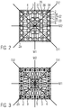
- Figure 2 shows a top view of the top 2a of a seepage block element 1.
- the rib structure 8 of the base wall 2, which allows water to pass through, can be clearly seen.
- the column tip receptacles 4 are provided in the structure 8 of the base wall between the columns 3.
- five or six columns 3 are arranged mirror-symmetrically to one center line M2 or to the other center line M1, with six or five column tip receptacles 4 being located between and next to the columns 3.
- three or two columns 3 are also arranged mirror-symmetrically to the other center line M1 or to a center line M2, two or three column tip receptacles 4 being located between and next to these columns 3 , Adjacent to the intersection of the two center lines M1, M2, a column 3 is arranged mirror-symmetrically to a center line M2, two column tip receptacles 4 being located between the two columns 3 on one center line M2.
- Figure 3 shows a top view of the underside 2b of a seepage block element 1, the hollow columns 3 with the oval cross section extending perpendicularly from the underside 2b of the base wall 2.
- the column tips 5 have a continuous opening 9, which allows water to pass through this opening 9 and the hollow columns 3.
- the pillar tip receptacles 4 and the pillars 3 are designed and arranged in such a way that, with two identical seepage block elements 1 and rotated by 90 ° relative to one another about the rotation axis A, the pillar tips 5 of the upper seepage block element 1 into the pillar tip receptacles 4 of the lower one Seepage block element 1 can be introduced or that, in the case of two identical and identically aligned seepage block elements 1, the columns 3 of the upper seepage block element 1 can be introduced into the columns 3 of the lower seepage block element 1.
- Figure 4 shows the composite elements from the Figure 1 , ie the two seepage block elements 1 and the base plate 6.
- An operating distance D1 results between the underside 2b of the upper base wall 2 and the upper side 2a of the lower base wall 2.
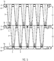
- Figure 5 shows a sectional view of the Figure 4 along BB.
- the column tips 5 with the openings 9 of the upper seepage block element 1 engage in the column tip receptacles 4 of the lower seepage block element 1, and the column tips 5 with the openings 9 of the lower seepage block element 1 engage in the receptacles 7 of the base plate 6.
- D1 there is an operating distance D1 between the underside 2b of the upper base wall 2 and the upper side 2a of the lower base wall 2 and a distance D2 between the underside 2b of the lower base wall 2 and the upper side 6a of the base plate 6, where D1 is equal to D2.
- the columns 3 are arranged in such a way that they are arranged mirror-symmetrically with respect to both center lines M1, M2 of the base wall 2 and not mirror-symmetrically with respect to both 45 ° diagonals DI1, DI2 of the base wall 2, with a reflection on the two 45 ° diagonals DI1, DI2 of the base wall 2 at the position of a column 3 a column tip holder 4 or at the position of a column tip holder 4 a column 3 comes to rest.
- This enables a symmetrical load input with identical seepage block elements 2, which are rotated by 90 ° relative to each other about the axis of rotation A.
- Figure 6 shows the line course of the wall 18 (solid line) of a first column 3 of the upper base wall 2 starting from a first point along a vertical plane, at which the first column 3 and a first column tip receptacle 4 of the upper base wall 2 directly adjoin one another, to the upper side 2a of the lower base wall 2, where the first column tip 5 of the first column 3 is introduced into a second column tip receptacle 4 of the lower base wall 2 and from there to the line course of the wall 19 (solid line) of a second column 3 of the lower base wall 2 starting from a second point at which the second column 3 and the second column tip receptacle 4 of the upper base wall 2 directly adjoin one another, so shows that this line course of the wall 18 of the first column 3 and the wall 19 of the second column 3 merges into one another.
- the line course of the wall 20 (dashed line) of the first column 3 and the wall 21 (dashed line) of the second column 3 merge into one another.
- the line course of the wall 20 of the first column 3 of the upper base wall 2 is shown along a vertical plane, starting from a first point at which the first column 3 and a third column tip receptacle 4 of the upper base wall 2 directly adjoin one another, to the top 2a of FIG lower base wall 2, where the first pillar tip 5 of the first pillar 3 is introduced into the second pillar tip receptacle 4 of the lower base wall 2 and from there to the line shape of the wall 21 of a third pillar 3 of the lower base wall 2 starting from a third location, where the third column 3 and the second column tip receptacle 4 of the upper base wall 2 directly adjoin one another.
- the forces which act from the first column 3 of the upper base wall 2 on the columns 3 of the lower base wall 2 are represented by two arrows 22, 24.
- One part of the force 22 is thus transferred to the second column 3 of the lower base wall 2, represented by the arrow 23, and the other part of the force 24 is transferred to the third column 3 of the lower base wall 2, represented by the arrow 25.
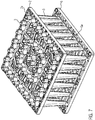
- Figure 7 shows an oblique view of the base plate 6, the lower percolation block element 1 and the upper percolation block element 1 cut off in the area of the columns 3, in order to be able to show the positions of the columns 3 of the upper percolation block element 1 relative to the lower percolation block element 1 more clearly.
- Figure 8 shows a side view of twenty stacked seepage block elements 1.
- This stacking possibility results from the fact that the columns 3 of the seepage block elements 1 are designed and arranged in such a way that, with identical and identically aligned seepage block elements 1, the columns 3 of an above seepage block element 1 into the columns 3 one below arranged seepage block element 1 can be introduced.
- a stacking distance D3 results from a base wall 2 arranged underneath.
- the seepage block elements 1 stacked one inside the other are arranged on a transport plate 10, which has feet 11 on its underside 10b, so that, for example, the fork of a forklift can be inserted under the transport plate 10.
- the transport plate 10 On the top 10a, the transport plate 10 has recesses 12 into which the column tips 5 of a seepage block element 1 can be introduced.
- D4 There is a distance D4 between the bottom 2b of the base wall 2 and the top 10a of the transport plate 10, D4 generally being equal to D1 and D2.
- the in the Figure 8 The arrangement shown of a plurality of nested block elements 1 stacked one inside the other, which are arranged on a transport plate 10, can be referred to as a transport unit.
- Figure 9 shows a sectional view of the stacked seepage block elements 1 and in particular the stacked columns 3 of the seepage block elements 1.
- a column tip 5 has a smaller cross section than the column 3, so that a step 13 is formed on the underside of the column 3, which in the stacked state of two seepage block elements 1 inside the hollow column 3 is positively introduced into a projection 14.
- the outside 15 of a column is generally smooth.
- Figure 10 shows the composite elements of the Figure 4 , which result in a seepage block 16 with side walls 17.
- the side walls 17 represent a termination of the upper or lower seepage block element 1 to the sides on which no further seepage block elements are arranged.
- the side walls each have a lattice structure, so that water can pass through the side walls 17.
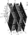
- Figure 11 shows an oblique view of four exemplary seepage block elements 26 with a rectangular base area and two rectangular base plates 27, which are not part of the invention.
- a seepage block element 26 with a base wall 31 with a rectangular base area consists of two identical seepage block elements 1, each with a base wall 1 with a square base area - as for example in FIG Figure 1 described - which are arranged side by side in the same orientation.
- the two identical seepage block elements 1, each with a square base area, for producing the base wall 31 with the rectangular base area were produced from a molded plastic part.
- a rectangular base plate 27 consists of two identical base plates 6, each with a square surface, as for example in FIG Figure 1 described, the two square base plates 6 for producing the rectangular base plate 27 being produced from a plastic part in the illustration.
- the columns 28 of the seepage block element 26 with a base wall 31 with a rectangular base area are designed and arranged in such a way that, in the case of two identical and identically aligned seepage block elements 26, the first columns 28 of the first seepage block element 26 can be inserted into and inserted into the second columns 28 of the second seepage block element 26 Stack of the two identical and aligned seepage block elements 26 can be formed.
- the base wall 31 comprises column tip receptacles 29, which are designed to receive column tips 30.
- a seepage block element 26 has an axis symmetry of 180 ° when rotated about a rotational symmetry axis A2 of the rectangular base surface, the rotational symmetry axis A2 passing through the intersection of the two diagonals DI3, DI4 of the rectangular base surface and running perpendicular to the rectangular base surface of the base wall 31.
- the rib structure of the base wall 31 was not in a seepage block element 26 with a rectangular base shown.
- two identical seepage block elements 26 with a rectangular base area are arranged rotated by 90 ° relative to one another about an axis of rotation A3 perpendicular to the square base area, so that part of the column tips 30 of the first Seepage block element 26 can be introduced into part of the column tip receptacles 29 of the second seepage block element 26 and an operating distance can be formed between the first and the second seepage block element 26.
- the axis of rotation A3 also passes through the intersection of the two 45 ° diagonals DI5, DI6 of the base wall 2 with the square base area.
- Figure 12 shows an oblique view of a schematically illustrated exemplary seepage block element 41 with a base wall 42 with a hexagonal base surface with which hollow columns 43 are connected, which is not part of the invention.
- Column tip receptacles 49 are arranged in the base wall 41 between and next to the columns 43 and are designed to receive the column tips of columns 43.
- the axis of rotational symmetry A4 and the axis of rotation A4 are the same; they run perpendicular to the base of the base wall 42 and go through the intersection of the triangular lines 44 of the hexagon shown in broken lines.
- the seepage block element 41 has an axis symmetry of 180 ° when rotating about the rotational symmetry phase A4.
- Figure 13 shows an oblique view of two exemplary seepage block elements 41, which are not part of the invention, each with a hexagonal base area - as in FIG Figure 12 described - wherein the two seepage block elements 41 are arranged rotated by 60 ° with respect to one another about the axis of rotation A4, so that the column tips 49 of the upper seepage block element 41 can be introduced into the column tip receptacles 49 of the lower seepage block element 41, as a result of which an operating distance between the underside of the upper base wall 42 and the top of the lower base wall 42 can be formed.
- the column tip of the column 50 of the upper seepage block element 41 can be introduced into the column tip receptacle 53 of the lower seepage block element 41; The same applies to the column tip of the column 51 and the column tip receptacle 54 as well as for the column tip of the column 52 and the column tip receptacle 55.
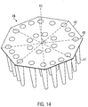
- Figure 14 shows an oblique view of a schematically illustrated example seepage block element 45 with a base wall 46 with an octagonal base area, which is not part of the invention.
- a plurality of hollow columns 47 are connected to the octagonal base area, the column tip receptacles arranged in the base wall 46 between and next to the columns 47 not being shown.
- the axis of rotational symmetry A5 and the axis of rotation A5 are the same; they run perpendicular to the base of the base wall 46 and go through the intersection of the triangular lines 48 of the octagon shown in broken lines.
- the seepage block element 45 has an axis symmetry of 180 ° upon rotation about the axis of symmetry A5.
Landscapes
- Health & Medical Sciences (AREA)
- Life Sciences & Earth Sciences (AREA)
- Engineering & Computer Science (AREA)
- Hydrology & Water Resources (AREA)
- Public Health (AREA)
- Water Supply & Treatment (AREA)
- Prostheses (AREA)
- Sewage (AREA)
Priority Applications (12)
| Application Number | Priority Date | Filing Date | Title |
|---|---|---|---|
| PT141794271T PT2980328T (pt) | 2014-08-01 | 2014-08-01 | Elemento de bloco de infiltração, bloco de infiltração e unidade de transporte |
| ES14179427T ES2776181T3 (es) | 2014-08-01 | 2014-08-01 | Elemento de bloque de infiltración, bloque de infiltración y unidad de transporte |
| PL14179427T PL2980328T3 (pl) | 2014-08-01 | 2014-08-01 | Element bloku rozsączającego, blok rozsączający i jednostka transportowa |
| EP14179427.1A EP2980328B1 (de) | 2014-08-01 | 2014-08-01 | Sickerblockelement, Sickerblock und Transporteinheit |
| DK14179427.1T DK2980328T3 (da) | 2014-08-01 | 2014-08-01 | Nedsivningsblokelement, nedsivningsblok og transportenhed |
| US15/032,759 US9896832B2 (en) | 2014-08-01 | 2014-10-21 | Percolation block element, percolation block, and transport unit |
| AU2014401974A AU2014401974B2 (en) | 2014-08-01 | 2014-10-21 | Percolation block element, percolation block, and transport unit |
| MYPI2016702765A MY183037A (en) | 2014-08-01 | 2014-10-21 | Percolation block element, percolation block, and transport unit |
| CA2927945A CA2927945C (en) | 2014-08-01 | 2014-10-21 | Percolation block element, percolation block, and transport unit |
| NZ719565A NZ719565A (en) | 2014-08-01 | 2014-10-21 | Percolation block element, percolation block, and transport unit |
| PCT/EP2014/072546 WO2016015786A1 (de) | 2014-08-01 | 2014-10-21 | Sickerblockelement, sickerblock und transporteinheit |
| CN201480059624.9A CN105705709B (zh) | 2014-08-01 | 2014-10-21 | 渗透块元件、渗透块以及传送单元 |
Applications Claiming Priority (1)
| Application Number | Priority Date | Filing Date | Title |
|---|---|---|---|
| EP14179427.1A EP2980328B1 (de) | 2014-08-01 | 2014-08-01 | Sickerblockelement, Sickerblock und Transporteinheit |
Publications (2)
| Publication Number | Publication Date |
|---|---|
| EP2980328A1 EP2980328A1 (de) | 2016-02-03 |
| EP2980328B1 true EP2980328B1 (de) | 2020-01-08 |
Family
ID=51260700
Family Applications (1)
| Application Number | Title | Priority Date | Filing Date |
|---|---|---|---|
| EP14179427.1A Active EP2980328B1 (de) | 2014-08-01 | 2014-08-01 | Sickerblockelement, Sickerblock und Transporteinheit |
Country Status (12)
| Country | Link |
|---|---|
| US (1) | US9896832B2 (da) |
| EP (1) | EP2980328B1 (da) |
| CN (1) | CN105705709B (da) |
| AU (1) | AU2014401974B2 (da) |
| CA (1) | CA2927945C (da) |
| DK (1) | DK2980328T3 (da) |
| ES (1) | ES2776181T3 (da) |
| MY (1) | MY183037A (da) |
| NZ (1) | NZ719565A (da) |
| PL (1) | PL2980328T3 (da) |
| PT (1) | PT2980328T (da) |
| WO (1) | WO2016015786A1 (da) |
Families Citing this family (29)
| Publication number | Priority date | Publication date | Assignee | Title |
|---|---|---|---|---|
| US20160097175A1 (en) * | 2013-03-26 | 2016-04-07 | Alton F. Parker | Aggregate replacement |
| WO2015087249A1 (en) * | 2013-12-10 | 2015-06-18 | De Groot Trevor | Embankment support |
| NL1040956B1 (en) * | 2014-09-19 | 2016-09-29 | Wavin Bv | A plastic infiltration unit, a system comprising a plurality of plastic infiltration units, a method of manufacturing an injection molded plastic pillar for an infiltration unit, a plastic base plate for use with a plastic infiltration unit, and a plastic infiltration system for deployment underground comprising a plastic infiltration unit and a plastic base plate. |
| US9732508B1 (en) * | 2016-04-21 | 2017-08-15 | Bio Clean Environmental Services, Inc. | Hexagonal module and assembly for storage of water underground |
| US11952767B2 (en) * | 2016-09-13 | 2024-04-09 | Bio Clean Environmental Services, Inc. | Underground storage system with V shaped support legs |
| US11220815B2 (en) | 2016-04-21 | 2022-01-11 | Bio Clean Environmental Services, Inc. | Underground storage system with V shaped support legs |
| US10151096B2 (en) * | 2016-04-21 | 2018-12-11 | Bio Clean Environmental Services, Inc. | Tessellation square module and underground storage system |
| US10151083B2 (en) | 2016-04-21 | 2018-12-11 | Bio Clean Environmental Services, Inc. | Honeycomb module and underground storage system |
| CN108204036A (zh) * | 2016-12-16 | 2018-06-26 | 张淮 | 注有钢筋的蓄水模块与斜池壁场地的组合 |
| DE202016107113U1 (de) * | 2016-12-19 | 2018-03-21 | Rehau Ag + Co | Rigolenhalbelement |
| DE202016107114U1 (de) * | 2016-12-19 | 2018-03-21 | Rehau Ag + Co | Rigolenhalbelement |
| DE102017105002A1 (de) * | 2017-03-09 | 2018-09-13 | ACO Severin Ahlmann GmbH & Co Kommanditgesellschaft | Rigoleneinheit, Rigolenkörper und Einsatzstück |
| DE102017105011A1 (de) * | 2017-03-09 | 2018-09-13 | ACO Severin Ahlmann GmbH & Co Kommanditgesellschaft | Rigolenkörper und Mittelplatte |
| EP3543168A1 (de) | 2018-03-23 | 2019-09-25 | Otto Graf GmbH Kunststofferzeugnisse | Verfahren zum transportfertigen stapeln von sickerblockelementen auf einer seecontainertauglichen palette |
| USD888192S1 (en) * | 2018-05-18 | 2020-06-23 | Pre-Con Products | Cell for water management system |
| NL2021404B1 (en) | 2018-07-27 | 2020-01-31 | Wavin Bv | A system and a method for building a road |
| JP7161382B2 (ja) * | 2018-11-21 | 2022-10-26 | エバタ株式会社 | 雨水等貯留浸透施設用仕切板及び側板、雨水等貯留浸透施設用構造体並びに雨水等貯留浸透施設 |
| CN111663633A (zh) * | 2019-03-08 | 2020-09-15 | 天昇电器工业株式会社 | 雨水蓄存及入渗设施 |
| US11041297B2 (en) * | 2019-11-15 | 2021-06-22 | Pre-Con Products | Water management system and methods |
| NL2024531B1 (en) | 2019-12-20 | 2021-09-08 | Wavin Bv | A plastic infiltration unit |
| US11980835B2 (en) * | 2020-07-27 | 2024-05-14 | Foley Products Company, Llc | Double-filter basket for stormwater retention system drain |
| WO2022133512A1 (en) * | 2020-12-22 | 2022-06-30 | Astral Property Pty Ltd | A plastics geocellular structural module, which are light, |
| US20230243143A1 (en) * | 2021-10-07 | 2023-08-03 | Advanced Drainage Systems, Inc | Stormwater management crate assembly with tapered columns |
| EP4413209A1 (en) | 2021-10-07 | 2024-08-14 | Advanced Drainage Systems, Inc. | Stormwater management crate assembly |
| US12247383B1 (en) | 2021-10-18 | 2025-03-11 | Infiltrator Water Technologies, Llc | Stormwater system having multiple plates and one-piece columns |
| DE202021106956U1 (de) | 2021-12-21 | 2023-03-22 | REHAU Industries SE & Co. KG | Rigolenanordnung |
| CR20240259A (es) | 2021-12-30 | 2024-08-19 | Advanced Drainage Syst | Caja de aguas pluviales con soportes |
| US20240247475A1 (en) * | 2023-01-23 | 2024-07-25 | Deeproot Green Infrastructure, Llc | Water storage system |
| USD1123575S1 (en) * | 2025-02-07 | 2026-04-28 | Thomas Green | Core plate |
Family Cites Families (10)
| Publication number | Priority date | Publication date | Assignee | Title |
|---|---|---|---|---|
| DE202004018319U1 (de) * | 2004-11-25 | 2005-04-28 | Heitker Gmbh | Sicker- und Drainagekörper aus einzelnen Systemelementen |
| JP2008031774A (ja) * | 2006-07-31 | 2008-02-14 | Mikuni Plast Kk | 地下貯水システム用充填部材 |
| FR2929630B1 (fr) | 2008-04-02 | 2011-11-25 | Aliaxis Participations | Bac de retention d'eau permettant de constituer par assemblage de bacs un dispositif de retention d'eau enfoui dans le sol |
| AU2009101081A4 (en) * | 2008-10-28 | 2009-11-26 | Ghee Lee, Alan Sian | Water storage retention/drainage tank or channel |
| NZ598415A (en) * | 2009-08-14 | 2013-08-30 | Ben Gooden | A modulated structural cell for supporting a tree root network |
| JP5661392B2 (ja) * | 2010-09-16 | 2015-01-28 | 株式会社ダイクレ | 貯水施設の施工法及び貯水ユニット |
| DE102011086016A1 (de) | 2011-11-09 | 2013-05-16 | Fränkische Rohrwerke Gebr. Kirchner Gmbh & Co. Kg | Rigoleneinheit und aus derartigen Rigoleneinheiten gebildete Transporteinheit |
| AU2012373593B2 (en) * | 2012-03-14 | 2017-08-24 | Sekisui Techno Molding Co., Ltd. | Structural member used in rainwater storage laminated structure |
| EP2896755A4 (en) * | 2012-04-05 | 2016-06-29 | Sekisui Techno Molding Co Ltd | COMPONENT FOR THE LAYER STRUCTURE OF A RAIN WATER TANK |
| CN103882910A (zh) * | 2014-03-15 | 2014-06-25 | 江苏劲驰环境工程有限公司 | 一种组合式雨水储存装置及其装配方法 |
-
2014
- 2014-08-01 DK DK14179427.1T patent/DK2980328T3/da active
- 2014-08-01 ES ES14179427T patent/ES2776181T3/es active Active
- 2014-08-01 PL PL14179427T patent/PL2980328T3/pl unknown
- 2014-08-01 EP EP14179427.1A patent/EP2980328B1/de active Active
- 2014-08-01 PT PT141794271T patent/PT2980328T/pt unknown
- 2014-10-21 MY MYPI2016702765A patent/MY183037A/en unknown
- 2014-10-21 US US15/032,759 patent/US9896832B2/en active Active
- 2014-10-21 AU AU2014401974A patent/AU2014401974B2/en active Active
- 2014-10-21 NZ NZ719565A patent/NZ719565A/en not_active IP Right Cessation
- 2014-10-21 CA CA2927945A patent/CA2927945C/en active Active
- 2014-10-21 CN CN201480059624.9A patent/CN105705709B/zh not_active Expired - Fee Related
- 2014-10-21 WO PCT/EP2014/072546 patent/WO2016015786A1/de not_active Ceased
Non-Patent Citations (1)
| Title |
|---|
| None * |
Also Published As
| Publication number | Publication date |
|---|---|
| PT2980328T (pt) | 2020-02-25 |
| CN105705709B (zh) | 2018-07-20 |
| DK2980328T3 (da) | 2020-04-06 |
| US9896832B2 (en) | 2018-02-20 |
| US20160265209A1 (en) | 2016-09-15 |
| EP2980328A1 (de) | 2016-02-03 |
| CA2927945A1 (en) | 2016-02-04 |
| PL2980328T3 (pl) | 2020-09-21 |
| AU2014401974A1 (en) | 2016-05-19 |
| AU2014401974B2 (en) | 2017-08-31 |
| ES2776181T3 (es) | 2020-07-29 |
| MY183037A (en) | 2021-02-08 |
| CA2927945C (en) | 2018-05-01 |
| CN105705709A (zh) | 2016-06-22 |
| WO2016015786A1 (de) | 2016-02-04 |
| NZ719565A (en) | 2018-01-26 |
Similar Documents
| Publication | Publication Date | Title |
|---|---|---|
| EP2980328A1 (de) | Sickerblockelement, Sickerblock und Transporteinheit | |
| EP3165687B1 (de) | Strukturkörper für ein rigolensystem und rigolensystem | |
| EP2592194B1 (de) | Rigoleneinheit und aus derartigen Rigoleneinheiten gebildete Transporteinheit | |
| EP2829484B1 (de) | Flaschenkasten mit höhenverstellbarem fachwerkeinsatz | |
| WO2003008282A1 (de) | Schachtelbehälter | |
| EP3636559B1 (de) | Stapelbare kiste | |
| DE3725160C1 (de) | Flachpalette | |
| EP2495373A2 (de) | Entwässerungssystem, Verfahren zu seiner Herstellung und Bauelemente hierfür | |
| EP3592909B1 (de) | Rigoleneinheit, rigolenkörper und einsatzstück | |
| WO2007137774A1 (de) | Systemkiste insbesondere für den transport von frischem fisch | |
| EP3377416B1 (de) | Behälter aus kunststoff | |
| EP1135303B1 (de) | Kunststoffbehälter mit deckel | |
| DE3643005C2 (de) | Bauelement zur Verwendung im Bauwesen und als Spielzeug | |
| EP1354825B1 (de) | Müllbehälter mit verstärkter Zapfen-Einheit | |
| EP1031276B1 (de) | Vorrichtung zur Aufzucht von Chicorée | |
| EP3626646B1 (de) | Stapelbare kiste | |
| EP4192751B1 (de) | Kunststoffbehälter | |
| EP1669214B1 (de) | Ablageschale | |
| DE202004015081U1 (de) | Klappbox mit Zentriernocken | |
| DE102015102307A1 (de) | Kasten aus Kunststoff, insbesondere Flaschenkasten | |
| WO2005012643A1 (de) | Gitterplatte | |
| WO2023118221A1 (de) | Transportsysten einer rigolenanordnung | |
| DE202010002894U1 (de) | Behälter | |
| DE29610935U1 (de) | Transport- und Kultivationspalette | |
| EP4407112A1 (de) | Abstandhalterleiste |
Legal Events
| Date | Code | Title | Description |
|---|---|---|---|
| PUAI | Public reference made under article 153(3) epc to a published international application that has entered the european phase |
Free format text: ORIGINAL CODE: 0009012 |
|
| AK | Designated contracting states |
Kind code of ref document: A1 Designated state(s): AL AT BE BG CH CY CZ DE DK EE ES FI FR GB GR HR HU IE IS IT LI LT LU LV MC MK MT NL NO PL PT RO RS SE SI SK SM TR |
|
| AX | Request for extension of the european patent |
Extension state: BA ME |
|
| 17P | Request for examination filed |
Effective date: 20160225 |
|
| RBV | Designated contracting states (corrected) |
Designated state(s): AL AT BE BG CH CY CZ DE DK EE ES FI FR GB GR HR HU IE IS IT LI LT LU LV MC MK MT NL NO PL PT RO RS SE SI SK SM TR |
|
| STAA | Information on the status of an ep patent application or granted ep patent |
Free format text: STATUS: EXAMINATION IS IN PROGRESS |
|
| 17Q | First examination report despatched |
Effective date: 20180716 |
|
| GRAP | Despatch of communication of intention to grant a patent |
Free format text: ORIGINAL CODE: EPIDOSNIGR1 |
|
| STAA | Information on the status of an ep patent application or granted ep patent |
Free format text: STATUS: GRANT OF PATENT IS INTENDED |
|
| INTG | Intention to grant announced |
Effective date: 20190725 |
|
| RIN1 | Information on inventor provided before grant (corrected) |
Inventor name: DER ERFINDER HAT AUF SEIN RECHT VERZICHTET, ALS SO |
|
| GRAS | Grant fee paid |
Free format text: ORIGINAL CODE: EPIDOSNIGR3 |
|
| GRAA | (expected) grant |
Free format text: ORIGINAL CODE: 0009210 |
|
| STAA | Information on the status of an ep patent application or granted ep patent |
Free format text: STATUS: THE PATENT HAS BEEN GRANTED |
|
| AK | Designated contracting states |
Kind code of ref document: B1 Designated state(s): AL AT BE BG CH CY CZ DE DK EE ES FI FR GB GR HR HU IE IS IT LI LT LU LV MC MK MT NL NO PL PT RO RS SE SI SK SM TR |
|
| REG | Reference to a national code |
Ref country code: GB Ref legal event code: FG4D Free format text: NOT ENGLISH |
|
| REG | Reference to a national code |
Ref country code: CH Ref legal event code: EP |
|
| REG | Reference to a national code |
Ref country code: DE Ref legal event code: R096 Ref document number: 502014013418 Country of ref document: DE |
|
| REG | Reference to a national code |
Ref country code: IE Ref legal event code: FG4D Free format text: LANGUAGE OF EP DOCUMENT: GERMAN |
|
| REG | Reference to a national code |
Ref country code: AT Ref legal event code: REF Ref document number: 1222882 Country of ref document: AT Kind code of ref document: T Effective date: 20200215 |
|
| REG | Reference to a national code |
Ref country code: PT Ref legal event code: SC4A Ref document number: 2980328 Country of ref document: PT Date of ref document: 20200225 Kind code of ref document: T Free format text: AVAILABILITY OF NATIONAL TRANSLATION Effective date: 20200217 |
|
| REG | Reference to a national code |
Ref country code: NL Ref legal event code: FP Ref country code: RO Ref legal event code: EPE |
|
| REG | Reference to a national code |
Ref country code: DK Ref legal event code: T3 Effective date: 20200403 |
|
| REG | Reference to a national code |
Ref country code: SE Ref legal event code: TRGR |
|
| REG | Reference to a national code |
Ref country code: NO Ref legal event code: T2 Effective date: 20200108 |
|
| REG | Reference to a national code |
Ref country code: LT Ref legal event code: MG4D |
|
| REG | Reference to a national code |
Ref country code: ES Ref legal event code: FG2A Ref document number: 2776181 Country of ref document: ES Kind code of ref document: T3 Effective date: 20200729 |
|
| PG25 | Lapsed in a contracting state [announced via postgrant information from national office to epo] |
Ref country code: RS Free format text: LAPSE BECAUSE OF FAILURE TO SUBMIT A TRANSLATION OF THE DESCRIPTION OR TO PAY THE FEE WITHIN THE PRESCRIBED TIME-LIMIT Effective date: 20200108 Ref country code: FI Free format text: LAPSE BECAUSE OF FAILURE TO SUBMIT A TRANSLATION OF THE DESCRIPTION OR TO PAY THE FEE WITHIN THE PRESCRIBED TIME-LIMIT Effective date: 20200108 Ref country code: LT Free format text: LAPSE BECAUSE OF FAILURE TO SUBMIT A TRANSLATION OF THE DESCRIPTION OR TO PAY THE FEE WITHIN THE PRESCRIBED TIME-LIMIT Effective date: 20200108 |
|
| PG25 | Lapsed in a contracting state [announced via postgrant information from national office to epo] |
Ref country code: BG Free format text: LAPSE BECAUSE OF FAILURE TO SUBMIT A TRANSLATION OF THE DESCRIPTION OR TO PAY THE FEE WITHIN THE PRESCRIBED TIME-LIMIT Effective date: 20200408 Ref country code: HR Free format text: LAPSE BECAUSE OF FAILURE TO SUBMIT A TRANSLATION OF THE DESCRIPTION OR TO PAY THE FEE WITHIN THE PRESCRIBED TIME-LIMIT Effective date: 20200108 Ref country code: LV Free format text: LAPSE BECAUSE OF FAILURE TO SUBMIT A TRANSLATION OF THE DESCRIPTION OR TO PAY THE FEE WITHIN THE PRESCRIBED TIME-LIMIT Effective date: 20200108 Ref country code: IS Free format text: LAPSE BECAUSE OF FAILURE TO SUBMIT A TRANSLATION OF THE DESCRIPTION OR TO PAY THE FEE WITHIN THE PRESCRIBED TIME-LIMIT Effective date: 20200508 |
|
| REG | Reference to a national code |
Ref country code: DE Ref legal event code: R097 Ref document number: 502014013418 Country of ref document: DE |
|
| PG25 | Lapsed in a contracting state [announced via postgrant information from national office to epo] |
Ref country code: SK Free format text: LAPSE BECAUSE OF FAILURE TO SUBMIT A TRANSLATION OF THE DESCRIPTION OR TO PAY THE FEE WITHIN THE PRESCRIBED TIME-LIMIT Effective date: 20200108 Ref country code: EE Free format text: LAPSE BECAUSE OF FAILURE TO SUBMIT A TRANSLATION OF THE DESCRIPTION OR TO PAY THE FEE WITHIN THE PRESCRIBED TIME-LIMIT Effective date: 20200108 Ref country code: SM Free format text: LAPSE BECAUSE OF FAILURE TO SUBMIT A TRANSLATION OF THE DESCRIPTION OR TO PAY THE FEE WITHIN THE PRESCRIBED TIME-LIMIT Effective date: 20200108 |
|
| PLBE | No opposition filed within time limit |
Free format text: ORIGINAL CODE: 0009261 |
|
| STAA | Information on the status of an ep patent application or granted ep patent |
Free format text: STATUS: NO OPPOSITION FILED WITHIN TIME LIMIT |
|
| 26N | No opposition filed |
Effective date: 20201009 |
|
| PG25 | Lapsed in a contracting state [announced via postgrant information from national office to epo] |
Ref country code: SI Free format text: LAPSE BECAUSE OF FAILURE TO SUBMIT A TRANSLATION OF THE DESCRIPTION OR TO PAY THE FEE WITHIN THE PRESCRIBED TIME-LIMIT Effective date: 20200108 |
|
| PG25 | Lapsed in a contracting state [announced via postgrant information from national office to epo] |
Ref country code: MC Free format text: LAPSE BECAUSE OF FAILURE TO SUBMIT A TRANSLATION OF THE DESCRIPTION OR TO PAY THE FEE WITHIN THE PRESCRIBED TIME-LIMIT Effective date: 20200108 |
|
| PG25 | Lapsed in a contracting state [announced via postgrant information from national office to epo] |
Ref country code: LU Free format text: LAPSE BECAUSE OF NON-PAYMENT OF DUE FEES Effective date: 20200801 |
|
| PG25 | Lapsed in a contracting state [announced via postgrant information from national office to epo] |
Ref country code: TR Free format text: LAPSE BECAUSE OF FAILURE TO SUBMIT A TRANSLATION OF THE DESCRIPTION OR TO PAY THE FEE WITHIN THE PRESCRIBED TIME-LIMIT Effective date: 20200108 Ref country code: MT Free format text: LAPSE BECAUSE OF FAILURE TO SUBMIT A TRANSLATION OF THE DESCRIPTION OR TO PAY THE FEE WITHIN THE PRESCRIBED TIME-LIMIT Effective date: 20200108 Ref country code: CY Free format text: LAPSE BECAUSE OF FAILURE TO SUBMIT A TRANSLATION OF THE DESCRIPTION OR TO PAY THE FEE WITHIN THE PRESCRIBED TIME-LIMIT Effective date: 20200108 |
|
| PG25 | Lapsed in a contracting state [announced via postgrant information from national office to epo] |
Ref country code: MK Free format text: LAPSE BECAUSE OF FAILURE TO SUBMIT A TRANSLATION OF THE DESCRIPTION OR TO PAY THE FEE WITHIN THE PRESCRIBED TIME-LIMIT Effective date: 20200108 Ref country code: AL Free format text: LAPSE BECAUSE OF FAILURE TO SUBMIT A TRANSLATION OF THE DESCRIPTION OR TO PAY THE FEE WITHIN THE PRESCRIBED TIME-LIMIT Effective date: 20200108 |
|
| PG25 | Lapsed in a contracting state [announced via postgrant information from national office to epo] |
Ref country code: GR Free format text: LAPSE BECAUSE OF FAILURE TO SUBMIT A TRANSLATION OF THE DESCRIPTION OR TO PAY THE FEE WITHIN THE PRESCRIBED TIME-LIMIT Effective date: 20200108 |
|
| PGFP | Annual fee paid to national office [announced via postgrant information from national office to epo] |
Ref country code: NL Payment date: 20250826 Year of fee payment: 12 |
|
| PGFP | Annual fee paid to national office [announced via postgrant information from national office to epo] |
Ref country code: ES Payment date: 20250902 Year of fee payment: 12 Ref country code: PT Payment date: 20250731 Year of fee payment: 12 |
|
| PGFP | Annual fee paid to national office [announced via postgrant information from national office to epo] |
Ref country code: DK Payment date: 20250822 Year of fee payment: 12 Ref country code: DE Payment date: 20250828 Year of fee payment: 12 |
|
| PGFP | Annual fee paid to national office [announced via postgrant information from national office to epo] |
Ref country code: NO Payment date: 20250829 Year of fee payment: 12 |
|
| PGFP | Annual fee paid to national office [announced via postgrant information from national office to epo] |
Ref country code: IT Payment date: 20250827 Year of fee payment: 12 Ref country code: PL Payment date: 20250801 Year of fee payment: 12 |
|
| PGFP | Annual fee paid to national office [announced via postgrant information from national office to epo] |
Ref country code: GB Payment date: 20250827 Year of fee payment: 12 Ref country code: BE Payment date: 20250822 Year of fee payment: 12 |
|
| PGFP | Annual fee paid to national office [announced via postgrant information from national office to epo] |
Ref country code: AT Payment date: 20250822 Year of fee payment: 12 Ref country code: FR Payment date: 20250826 Year of fee payment: 12 |
|
| PGFP | Annual fee paid to national office [announced via postgrant information from national office to epo] |
Ref country code: CH Payment date: 20250901 Year of fee payment: 12 Ref country code: SE Payment date: 20250827 Year of fee payment: 12 |
|
| PGFP | Annual fee paid to national office [announced via postgrant information from national office to epo] |
Ref country code: CZ Payment date: 20250731 Year of fee payment: 12 Ref country code: IE Payment date: 20250824 Year of fee payment: 12 |
|
| PGFP | Annual fee paid to national office [announced via postgrant information from national office to epo] |
Ref country code: RO Payment date: 20250804 Year of fee payment: 12 |