EP2979256B1 - Beförderung von speisen innerhalb verkaufsautomat mit integrierter mikrowelle - Google Patents
Beförderung von speisen innerhalb verkaufsautomat mit integrierter mikrowelle Download PDFInfo
- Publication number
- EP2979256B1 EP2979256B1 EP14724291.1A EP14724291A EP2979256B1 EP 2979256 B1 EP2979256 B1 EP 2979256B1 EP 14724291 A EP14724291 A EP 14724291A EP 2979256 B1 EP2979256 B1 EP 2979256B1
- Authority
- EP
- European Patent Office
- Prior art keywords
- product
- vending machine
- microwave oven
- closure element
- receptacle
- Prior art date
- Legal status (The legal status is an assumption and is not a legal conclusion. Google has not performed a legal analysis and makes no representation as to the accuracy of the status listed.)
- Not-in-force
Links
- 238000002360 preparation method Methods 0.000 claims description 16
- 238000000034 method Methods 0.000 claims description 5
- 239000000463 material Substances 0.000 claims description 2
- 230000004308 accommodation Effects 0.000 claims 1
- 230000000717 retained effect Effects 0.000 claims 1
- 238000007789 sealing Methods 0.000 claims 1
- 238000010438 heat treatment Methods 0.000 description 15
- 235000013305 food Nutrition 0.000 description 6
- 235000012054 meals Nutrition 0.000 description 4
- 230000005855 radiation Effects 0.000 description 2
- 239000012780 transparent material Substances 0.000 description 2
- 238000012935 Averaging Methods 0.000 description 1
- 229920005372 Plexiglas® Polymers 0.000 description 1
- 230000001133 acceleration Effects 0.000 description 1
- 230000004913 activation Effects 0.000 description 1
- 230000009172 bursting Effects 0.000 description 1
- 238000004140 cleaning Methods 0.000 description 1
- 238000010276 construction Methods 0.000 description 1
- 238000011109 contamination Methods 0.000 description 1
- 230000001419 dependent effect Effects 0.000 description 1
- 238000004880 explosion Methods 0.000 description 1
- 230000014759 maintenance of location Effects 0.000 description 1
- 239000004033 plastic Substances 0.000 description 1
- 229920003023 plastic Polymers 0.000 description 1
- 239000004926 polymethyl methacrylate Substances 0.000 description 1
- 230000001902 propagating effect Effects 0.000 description 1
- 235000021150 warm meals Nutrition 0.000 description 1
Images


Classifications
-
- G—PHYSICS
- G07—CHECKING-DEVICES
- G07F—COIN-FREED OR LIKE APPARATUS
- G07F11/00—Coin-freed apparatus for dispensing, or the like, discrete articles
- G07F11/02—Coin-freed apparatus for dispensing, or the like, discrete articles from non-movable magazines
- G07F11/04—Coin-freed apparatus for dispensing, or the like, discrete articles from non-movable magazines in which magazines the articles are stored one vertically above the other
- G07F11/16—Delivery means
- G07F11/165—Delivery means using xyz-picker or multi-dimensional article picking arrangements
-
- G—PHYSICS
- G07—CHECKING-DEVICES
- G07F—COIN-FREED OR LIKE APPARATUS
- G07F9/00—Details other than those peculiar to special kinds or types of apparatus
- G07F9/10—Casings or parts thereof, e.g. with means for heating or cooling
- G07F9/105—Heating or cooling means, for temperature and humidity control, for the conditioning of articles and their storage
-
- G—PHYSICS
- G07—CHECKING-DEVICES
- G07F—COIN-FREED OR LIKE APPARATUS
- G07F11/00—Coin-freed apparatus for dispensing, or the like, discrete articles
- G07F11/46—Coin-freed apparatus for dispensing, or the like, discrete articles from movable storage containers or supports
- G07F11/50—Coin-freed apparatus for dispensing, or the like, discrete articles from movable storage containers or supports the storage containers or supports being rotatably mounted
- G07F11/52—Coin-freed apparatus for dispensing, or the like, discrete articles from movable storage containers or supports the storage containers or supports being rotatably mounted about horizontal axes
-
- G—PHYSICS
- G07—CHECKING-DEVICES
- G07F—COIN-FREED OR LIKE APPARATUS
- G07F17/00—Coin-freed apparatus for hiring articles; Coin-freed facilities or services
- G07F17/0064—Coin-freed apparatus for hiring articles; Coin-freed facilities or services for processing of food articles
- G07F17/0078—Food articles which need to be processed for dispensing in a hot or cooked condition, e.g. popcorn, nuts
-
- H—ELECTRICITY
- H05—ELECTRIC TECHNIQUES NOT OTHERWISE PROVIDED FOR
- H05B—ELECTRIC HEATING; ELECTRIC LIGHT SOURCES NOT OTHERWISE PROVIDED FOR; CIRCUIT ARRANGEMENTS FOR ELECTRIC LIGHT SOURCES, IN GENERAL
- H05B6/00—Heating by electric, magnetic or electromagnetic fields
- H05B6/64—Heating using microwaves
- H05B6/80—Apparatus for specific applications
- H05B6/808—Microwave heating adapted for vending machines
Definitions
- the present invention relates to a vending machine for food according to the features of claim 1.
- vending machines have been known for many years in a variety of configurations.
- such vending machines provide a microwave oven to heat the food selected by the user so that a ready-to-eat hot meal can be provided to the user.
- a suitable solution is from the DE 10 2009 040 669 A1 previously known.
- There it is provided to load a built-in vending machine microwave oven via a hinged door with the selected product to turn off this in the microwave oven to close the door and after the heating process to open the door and promote the product to a product issue.
- FR2681217A EP1688894A1 .
- Such vending machines are often located in public facilities such as airports, train stations and the like, as well as in larger companies, offices and self-service canteens. Basically, they are always placed where users have little time to eat a meal. All the more urgent is the desire to provide the desired meal in the shortest possible time frame, while the highest possible quality is to be delivered. In particular, the quality of warm meals is also influenced by the fact that as complete and uniform heating must have taken place.
- the individual meals are held in product trays, which are visible through a window in the machine. Therefore, a user of the vending machine can first make his selection from the display and then receive the specially selected product after its preparation, essentially heating.
- the specially selected product is conveyed from the product store to a microwave oven and from there to the product dispenser.
- the product is in the product storage, from which it must be collected for heating. For heating, it is placed in a microwave oven, which must be sealed microwave-tight for the heating process, so that leakage of the microwave radiation is prevented. After the heating process, the microwave oven is opened again, the product taken out and brought to the product output, to which again a conveyor must be provided.
- the present invention is based on the object of proposing a vending machine for food whose delivery processes Compared to known vending machines are significantly accelerated and its construction is simplified at the same time.
- the closure element for closing the microwave oven is movable independently of the microwave oven within the housing and has a receptacle in which the product to be heated can be transported.
- the closure element for the microwave oven is thus approach the product storage in a first step after selecting the desired product, where the product tray is inserted into the receptacle of the closure element. Together with the product shell, the closure element will then move into the area of the microwave oven, drive the product dish into the preparation space of the microwave oven and close it microwave-tight.
- the closure member retracts the product tray from the microwave oven, places the product tray in the area of a product dispenser, and dispenses the product tray beyond the product dispenser to the customer.
- This concept of a one-time receipt of a product shell and its retention to the final output eliminates during the heating process, all gripping operations, which had been required in earlier concepts and had to be handled with a greater expenditure of time. This eliminates the process of closing and opening the shutter opening of the microwave oven, after this process is connected to the conveying process. As a result, the invention enables extremely rapid preparation of the product in the product tray by minimizing the time-consuming transport of the product.
- the product storage in which the product trays are held, is formed from a plurality of magazines which can be removed individually from the casing of the vending machine.
- the product trays can be held up to the selection by the user of the vending machine.
- a product tray is removed from the magazine.
- Such a magazine can be closed on the visible side of the user by a hinged door, so that by a forward conveying a product shell, the swing door is pressed and the supported by the pivoting door product tray can slide into the receptacle of the closure element.
- the swing doors offer the opportunity to operate magazines each at different temperature levels, since a temperature equalization over the front openings, which would be present without the swing door, is eliminated.
- the closure element with the receptacle attached to it can thus move into the region below the desired product and then accept this product in the manner described above.
- the closure element is tilted so that the direction of incidence of the product shell can be achieved.
- the closure element is further held on a tiltable arm, and with some advantage also on the arm rotatable.
- the arm is preferably with a lift connected, which can spend the entire arrangement within the housing of the vending machine to any position of the product storage.
- the receptacle can also be adapted in its shape to the shape of the product shells, which can be shaped so that a centering takes place in the receptacle. This is easily possible with round product trays, where a centering can be omitted due to the circular symmetry.
- the receptacle can specify a preferred direction into which the product tray is then aligned when it collapses. As a result, the product shell at a later time in the microwave oven receives a defined position, which can take place due to the uniform distances to the walls of the preparation chamber of the microwave oven efficient heating.
- the receptacle preferably forms a substantially oval collecting basket, which is suitable for receiving substantially all forms of common product trays, so that even differently shaped product trays can be held and offered simultaneously in the vending machine.
- the receptacle also has a position switch which is actuated as soon as a product shell has fallen into the receptacle.
- a position switch which is actuated as soon as a product shell has fallen into the receptacle.
- the closure element moves with the recorded in the receptacle product tray in a lower portion of the vending machine, in particular below a feed opening of the microwave oven.
- the microwave oven can also be moved on a rail assembly from a rest position to a working position, so far to meet after passing the height level of the microwave oven through the closure element this and to shorten the travel of the elevator and arm.
- the closure element can then move into a closed position of the microwave oven, wherein the product dish is then in the closed position in the interior of the preparation space of the microwave oven.
- the receptacle may advantageously be made of a microwave-transparent material, so that the product shell can be reached on all sides by the microwaves.
- a bulge of the lid of the product shell in the range of about two centimeters can be pronounced.
- the tool will then hit the lid after about a centimeter of curvature and eventually retract into the lid up to one centimeter.
- the tool will still be far away from the product, so that it can not come into contact with the product. This prevents contamination of the tool by the product.
- an eccentric roller can be provided in the region of the closure element or the microwave oven, which engages in the closure position of the closure element either the product shell or the receptacle from below and at least on one side moves up and down by a rotation about an eccentric axis.
- the product held on the closing element leaves the microwave oven again and, in the course of a further rotation of either the receptacle or the entire closing element, ejects the product dish from the housing via a product outlet.
- the product output can be assigned at least one means for detecting a machine-readable code, for example a barcode, arranged on the product tray. This can ensure that only authorized products are kept in the vending machine. Is detected at issue, that an unauthorized barcode has been found, so the operation of the vending machine can be suspended until a new activation.
- FIG. 1 shows a vending machine 10, which is enclosed by a housing 11 in which both a series of magazines 13 with a plurality of product trays 16 for selection by a customer, as well as a microwave oven 30 and an unspecified automatic cutlery output 17 are kept ready.
- a closing element 20 which has a receptacle 21 in the form of a collecting basket, moves into a position below the magazine compartment with the desired product tray 16. In this position, a conveying spiral 15 of the magazine 13 makes a rotation through which a product tray 16 is conveyed to the closure member 20 and the receptacle 21 to.
- the magazine 13 concealing pivoting door 14, which is made of Plexiglas to obtain the transparency for the customer, disengage to a stop, so that an incidence path of the product shell 16 is formed in the receptacle 21.
- the receptacle 21 additionally has a receiving funnel 22, which simplifies centering of the product pan 16 in the receptacle 21.
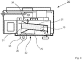
- FIG. 2 shows the same vending machine 10 in a side view, in which it can be seen that the magazines 13 are filled with a plurality of product trays 16, which can be successively conveyed out of the magazines 13 by rotation of the conveyor spirals 15 while pushing the pivot door 14 away.
- the closure element 20, which carries the receptacle 21 and then also the product shell 16 spend this in a microwave oven 30, in which the receptacle 21 with the product shell 16 enters via a bottom-side access 32.
- the closure element 20 For movement of the closure element 20 within the vending machine 10, the closure element 20 is mounted on an arm 23, which via a Elevator 24 can be moved in height.
- the arm 23 allows an inclination of the closure element 20 and is in the width of the vending machine 10 movable.
- FIG. 3 shows the next step, in which now the closure element 20 has been spent with the recorded in the receptacle 21 product shell 16 in an area below the microwave oven 30 by means of the elevator 24.
- the closure element 20 was placed on the arm 23 in a horizontal position. In this deep position, the microwave oven 30 is now moved out via rails 33 under the magazines 13 and thus brought into a position above the closure element 20.
- the closure element 20 will now insert the product shell 16 through the bottom access 32 of the microwave oven 30 into its preparation space 31 and at the same time seal the microwave oven 30 microwave-tight.
- FIG. 4 shows the microwave oven with the product retracted therein, which is held in the receptacle 21.
- the microwave oven is microwave-tightly locked on the bottom side by the closure element 20, so that a separate step for closing a door can be omitted.
- an eccentric roller 35 is arranged, which engages over a slot through the closure member through the receptacle 21 and this moves in the course of rotation about an eccentric axis 36 up and down. Due to a bulging of the lid of the product tray 16, this lid also engages a tool 34, which pierces the lid and thus helps to reduce the internal pressure of the product trays 16. In this case, the tool 34 is arranged so high that when the bulge of the lid of the product pan 16 recedes, the tool is no longer in engagement with the product pan 16. Due to the fact that the receptacle 21 is formed of a microwave transparent material, a uniform circulation of the microwaves within the preparation space 31 is allows.
- the product shell 16 has more or less the same distance from all the walls of the preparation space 31. Due to the exact averaging of the product in the preparation chamber 31, the preparation time is approximately halved compared to a randomly placed product because of the associated uniform irradiation by microwaves. In addition, it is possible to circulate the resulting hot air around the product pan 16, as in FIG FIG. 5 indicated.
- FIG. 6 again shows the entire vending machine 10 in a lateral sectional view, wherein in the position shown first the closure member 20 was driven with the receptacle 21 down, the microwave oven 30 is moved back over the rails 31 back to its rest position and the closure member 20 by means of the elevator 24th was spent on the height of a product issue 12. At the same time a rotation of the receptacle 21 by 180 ° took place, so that now the receiving hopper 22 points to the product output 12.
- the product tray 16 is output through the product output 12, wherein at the same time by means arranged in the product dispenser 12 means for detecting a bar code, in particular a bar code scanner, it is verified that the product tray 16 is an acceptable product.
- vending machine which provides a new transport concept for the product shells to be heated, in which the closure element of the microwave oven has a receptacle with which the product is picked up from a product store, placed in the microwave oven and finally led to the product output, without the Having to put down the product in between.
Landscapes
- Physics & Mathematics (AREA)
- General Physics & Mathematics (AREA)
- Life Sciences & Earth Sciences (AREA)
- Engineering & Computer Science (AREA)
- Food Science & Technology (AREA)
- Electromagnetism (AREA)
- Vending Machines For Individual Products (AREA)
Description
- Die vorliegende Erfindung betrifft einen Verkaufsautomaten für Speisen gemäß den Merkmalen von Anspruch 1. Derartige Verkaufsautomaten sind bereits seit vielen Jahren in unterschiedlichsten Ausgestaltungen bekannt. Insbesondere sehen solche Verkaufsautomaten einen Mikrowellenofen vor, um die vom Benutzer ausgewählten Speisen zu erwärmen, so dass dem Benutzer eine verzehrfertige, warme Mahlzeit bereitgestellt werden kann. Eine entsprechende Lösung ist aus der
DE 10 2009 040 669 A1 vorbekannt. Dort ist es vorgesehen, einen in den Verkaufsautomaten integrierten Mikrowellenofen über eine Schwenktür mit dem ausgewählten Produkt zu beschicken, dieses in dem Mikrowellenofen abzustellen, die Tür zu verschließen und nach dem Erwärmungsvorgang die Tür wieder zu öffnen und das Produkt zu einer Produktausgabe zu fördern. Weiterer Stand der Technik ist ausFR2681217A EP1688894A1 ,CA2153738A1 undWO2008/141746A1 bekannt. Derartige Verkaufsautomaten befinden sich häufig in öffentlichen Einrichtungen wie Flughäfen, Bahnhöfen und dergleichen sowie in größeren Firmen, Ämtern und Selbstbedienungskantinen. Im Grunde werden sie immer dort aufgestellt, wo die Benutzer für den Verzehr einer Mahlzeit nur wenig Zeit mitbringen. Umso vordringlicher ist das Bestreben, die gewünschte Mahlzeit in einem möglichst kurzen Zeitrahmen zur Verfügung zu stellen, wobei gleichzeitig eine möglichst hohe Qualität geliefert werden soll. Insbesondere wird die Qualität bei warmen Mahlzeiten auch dadurch beeinflusst, dass eine möglichst vollständige und gleichmäßige Erwärmung stattgefunden haben muss. - Innerhalb des Verkaufsautomaten werden die einzelnen Mahlzeiten in Produktschalen vorgehalten, welche über ein Sichtfenster im Automaten einsehbar sind. Daher kann ein Benutzer des Verkaufsautomaten zunächst seine Auswahl anhand der Auslage treffen und dann das speziell ausgewählte Produkt nach dessen Zubereitung, im Wesentlichen der Erwärmung, erhalten. Üblicherweise wird hierzu das speziell ausgewählte Produkt aus dem Produktlager hin zu einem Mikrowellenofen und von dort aus zur Produktausgabe gefördert. Dabei finden jedoch mehrere Brüche in der Transportkette statt. Zunächst befindet sich das Produkt in dem Produktlager, aus welchem es zur Erwärmung abgeholt werden muss. Zur Erwärmung wird es in einen Mikrowellenofen verbracht, welcher für den Erwärmungsvorgang mikrowellendicht verschlossen werden muss, so dass ein Austreten der Mikrowellenstrahlung verhindert wird. Nach dem Erwärmungsvorgang wird der Mikrowellenofen wieder geöffnet, das Produkt herausgenommen und zur Produktausgabe gebracht, wozu wieder eine Fördereinrichtung vorgesehen sein muss.
- Das positionsgenaue Aufnehmen und wieder Ablegen der Produktschalen erfordert einen großen Aufwand, welcher im Betrieb mit einer relativ langen Zeitdauer einhergeht, das Produkt durch den Verkaufsautomaten zu befördern. Um die Wartezeit für den Kunden bei gleichbleibender Qualität zu verkürzen, werden vorliegend Konzepte gesucht, um insbesondere die Beförderung innerhalb des Verkaufsautomaten zu verbessern, zu beschleunigen und zu vereinfachen.
- Gleichzeitig ist es für den Betreiber von Verkaufsautomaten uninteressant, eine Beschleunigung auf der Basis deutlich höherer Anschaffungskosten des Verkaufsautomaten zu erkaufen. Nachdem die verkauften Produkte üblicherweise preislich unterhalb von frisch zubereiteten Speisen liegen, ist die Gewinnspanne beim Verkauf derartiger Speisen als eher klein anzusehen.
- Der vorliegenden Erfindung liegt vor diesem Hintergrund die Aufgabe zu Grunde, einen Verkaufsautomaten für Speisen vorzuschlagen, dessen Fördervorgänge im Vergleich zu bekannten Verkaufsautomaten deutlich beschleunigt sind und dessen Konstruktion gleichzeitig vereinfacht wird.
- Dies gelingt durch einen Verkaufsautomaten für Speisen gemäß den Merkmalen des Anspruches 1. Weitere sinnvolle Ausgestaltungen eines derartigen Verkaufsautomaten können den Unteransprüchen entnommen werden.
- Erfindungsgemäß ist vorgesehen, dass das Verschlusselement zum Verschließen des Mikrowellenofens unabhängig von dem Mikrowellenofen innerhalb des Gehäuses verfahrbar ist und eine Aufnahme aufweist, in welcher das zu erwärmende Produkt transportiert werden kann. Das Verschlusselement für den Mikrowellenofen wird also in einem ersten Schritt nach der Auswahl des gewünschten Produktes das Produktlager anfahren, wo die Produktschale in die Aufnahme des Verschlusselementes eingelegt wird. Zusammen mit der Produktschale wird das Verschlusselement dann in den Bereich des Mikrowellenofens fahren, mit der Produktschale in den Zubereitungsraum des Mikrowellenofens einfahren und diesen dabei mikrowellendicht verschließen. Nach einer Erwärmungsphase fährt das Verschlusselement die Produktschale wieder aus dem Mikrowellenofen heraus, bringt die Produktschale in den Bereich einer Produktausgabe und gibt die Produktschale über die Produktausgabe an den Kunden hinaus.
- Durch dieses Konzept einer einmaligen Entgegennahme einer Produktschale und deren Festhalten bis zur letztendlichen Ausgabe entfallen während des Erwärmungsvorgangs sämtliche Greifvorgänge, welche bei früheren Konzepten erforderlich gewesen sind und mit größerem Zeitaufwand bewältigt werden mussten. Dazu entfällt der Vorgang des Schließens und Öffnens der Verschlussöffnung des Mikrowellenofens, nachdem auch dieser Vorgang mit dem Fördervorgang verbunden wird. Im Ergebnis ermöglicht also die Erfindung eine äußerst schnelle Zubereitung des Produktes in der Produktschale, indem die Zeit raubende Beförderung des Produktes auf ein Minimum reduziert wird.
- Im Einzelnen kann es vorgesehen sein, dass das Produktlager, in welchem die Produktschalen vorgehalten werden, aus einer Mehrzahl von dem Gehäuse des Verkaufsautomaten einzeln entnehmbaren Magazinen gebildet ist. In den einzelnen Magazinen können die Produktschalen bis zur Auswahl durch den Benutzer des Verkaufsautomaten vorgehalten werden.
Auf eine Auswahl des Kunden hin wird eine Produktschale aus dem Magazin herausgefördert. Dies wird mithilfe von Förderspiralen realisiert, in welche die Produkte eingelegt sind und durch deren Drehen die Produktschalen vorwärts bewegt werden können.
Ein derartiges Magazin kann auf der Sichtseite des Benutzers durch eine Schwenktür abgeschlossen sein, so dass durch ein Vorwärtsfördert einer Produktschale die Schwenktür aufgedrückt wird und die durch die Schwenktür abgestützte Produktschale in die Aufnahme des Verschlusselementes eingleiten kann. Zur verbesserten Führung durch die Schwenktüre ist diese in ihrem Öffnungswinkel begrenzt, so dass ein zu weites Aufklappen der Schwenktüre verhindert ist. Zudem bieten die Schwenktüren die Möglichkeit, Magazine jeweils auf unterschiedlichen Temperaturniveaus zu betreiben, da eine Temperaturangleichung über die vorderen Öffnungen, welche ohne die Schwenktüre vorhanden wären, entfällt. Außerdem ist im Falle einer Befüllung eines Magazins kein Temperaturabfall hinsichtlich der anderen Magazine, während die Schwenktüren bei der Befüllung geschlossen sind, zu erwarten.
Auf eine Benutzerauswahl hin kann also das Verschlusselement mit der an ihm befestigten Aufnahme in den Bereich unterhalb des gewünschten Produkts verfahren und dieses Produkt dann in oben beschriebener Art und Weise entgegennehmen. Hierzu ist das Verschlusselement derart neigbar dass die Einfallrichtung der Produktschale erreicht werden kann. Das Verschlusselement wird dazu ferner an einem neigbaren Arm gehalten, sowie mit einigem Vorteil auch auf dem Arm drehbar. Der Arm ist vorzugsweise mit einem Aufzug verbunden, welcher die Gesamtanordnung innerhalb des Gehäuses des Verkaufsautomaten zu beliebigen Positionen des Produktlagers verbringen kann. - Alternativ zu einer Drehbarkeit des gesamten Verschlusselementes auf dem Arm ist es auch möglich, lediglich die Aufnahme auf dem Verschlusselement drehbar zu halten, so dass praktisch lediglich das Produkt auf dem Verschlusselement gedreht wird, das Verschlusselement jedoch immer in der gleichen Grundlage bleibt. Eine solche Lösung erfordert einen deutlich kleineren Platzbedarf in dem Gehäuse.
- Die Aufnahme kann ferner in ihrer Formgebung an die Form der Produktschalen angepasst sein, welche so geformt sein können, dass eine Zentrierung in der Aufnahme stattfindet. Dies ist ohne Weiteres möglich bei runden Produktschalen, wo eine Zentrierung auch aufgrund der Kreissymmetrie entfallen kann. Beispielsweise bei oval gestalteten Produktschalen kann die Aufnahme eine Vorzugsrichtung vorgeben, in welche die Produktschale dann beim Einfallen ausgerichtet wird. Hierdurch erhält die Produktschale zum späteren Zeitpunkt in den Mikrowellenofen eine definierte Position, wodurch aufgrund der gleichmäßigen Abstände zu den Wänden des Zubereitungsraums des Mikrowellenofens eine effiziente Erwärmung stattfinden kann.
- Die Aufnahme bildet jedoch vorzugsweise einen im Wesentlichen ovalen Fangkorb aus, der sich zur Aufnahme von weitgehend allen Formen gängiger Produktschalen eignet, so dass auch verschiedenartig geformte Produktschalen gleichzeitig im Verkaufsautomaten vorgehalten und angeboten werden können.
- Mit einigem Vorteil weist die Aufnahme zudem einen Positionsschalter auf, der betätigt wird, sobald eine Produktschale in die Aufnahme eingefallen ist. In dem Fall, dass aufgrund der Drehung der Förderspirale keine vollständige Freigabe der Produktschale erfolgt, mithin die Produktschale in der Förderspirale hängenbleibt, wird dies angesichts des Erreichens der gewünschten Förderposition der Förderspirale und dem fehlenden Auslösen des Positionsschalters festgestellt, woraufhin die Förderspirale um eine zusätzliche Teildrehung weitergedreht wird, bis der Positionsschalter betätigt wird. Anschließend wird die Förderspirale wieder auf die eigentliche Zielposition zurückgedreht.
- Sodann verfährt das Verschlusselement mit der in der Aufnahme aufgenommenen Produktschale in einen unteren Bereich des Verkaufsautomaten, insbesondere unterhalb einer Zuführöffnung des Mikrowellenofens. Seine tief liegende Anordnung ermöglicht eine äußerst kompakte Bauform des Verkaufsautomaten, da der ohnehin vorhandene Raum unterhalb des Produktlagers hierdurch genutzt werden kann. Der Mikrowellenofen kann ferner auf einer Schienenanordnung aus einer Ruheposition in eine Arbeitsposition verfahrbar sein, um insoweit nach einem Passieren des Höhenlevels des Mikrowellenofens durch das Verschlusselement diesem entgegenzukommen und den Fahrweg von Aufzug und Arm zu verkürzen. Das Verschlusselement kann dann in eine Verschlussposition des Mikrowellenofens fahren, wobei die Produktschale sich in der Verschlussposition dann im Inneren des Zubereitungsraums des Mikrowellenofens befindet. Die Aufnahme kann vorteilhafterweise hierbei aus einem mikrowellendurchlässigen Material hergestellt sein, so dass die Produktschale allseits von den Mikrowellen erreicht werden kann.
- Nach dem Einfahren der Produktschale in den Mikrowellenofen wird im Rahmen der Erwärmung des Produkts in der Produktschale deren üblicherweise aus einem Kunststoffmaterial gefertigter Deckel sich aufgrund der Ausdehnung des Produkts durch die Erwärmung aufwölben. Im Zuge dieser Aufwölbung gerät der Deckel der Produktschale in Eingriff eines Werkzeugs zum lokalen Eröffnen der Produktschale, welches in dem Mikrowellenofen angeordnet ist. Es handelt sich hierbei beispielsweise um ein im Deckenbereich des Mikrowellenofens abgehängtes Messer oder eine Nadel oder dergleichen, welches jedoch so weit im oberen Bereich des Mikrowellenofens angeordnet ist, dass die Klinge oder Spitze des Werkzeugs nach einem Eröffnen des Deckels der Produktschale durch den Rückgang der Aufblähung des Deckels wieder aus der Produktschale austritt. Durch eine solche punktuelle Eröffnung ist ein Aufplatzen der Produktschale durch einen inneren Überdruck vermieden. Ein solches Aufplatzen könnte anderenfalls zu einer Explosion der Produktschale im Mikrowellenofen führen, was durch eine aufwändige Reinigung wieder beseitigt werden müsste. Das punktuelle Eröffnen der Produktschalen dient somit zuvorderst hygienischen Zielen.
- Konkret kann beispielsweise eine Aufwölbung des Deckels der Produktschale im Bereich von etwa zwei Zentimetern ausgeprägt sein. Das Werkzeug wird dann etwa nach einem Zentimeter Aufwölbung auf den Deckel treffen und schließlich bis zu einem Zentimeter in den Deckel einfahren. Hierdurch wird das Werkzeug von dem Produkt immer noch weit entfernt sein, so dass es mit dem Produkt nicht in Berührung kommen kann. Eine Verunreinigung des Werkzeugs durch das Produkt ist damit verhindert.
- Für eine verbesserte Gleichmäßigkeit der Erwärmung kann im Bereich des Verschlusselementes oder des Mikrowellenofens eine Exzenterrolle vorgesehen sein, welche in der Verschlusslage des Verschlusselementes entweder die Produktschale oder die Aufnahme von unten greift und durch eine Drehung um eine Exzenterachse herum wenigstens einseitig auf und ab bewegt. Aufgrund dieser Bewegung wird dafür gesorgt, dass sich im Zubereitungsraum des Mikrowellenofens ausbreitenden Mikrowellenstrahlen gleichmäßig alle Bereiche der Produktschale erreichen, wodurch eine schnellere, gleichmäßigere Erwärmung des Produktes gewährleistet wird.
- Anschließend wird das an dem Verschlusselement gehaltene Produkt den Mikrowellenofen wieder verlassen und im Zuge einer weiteren Drehung entweder der Aufnahme oder des gesamten Verschlusselementes die Produktschale über eine Produktausgabe aus dem Gehäuse auswerfen. Hierbei kann der Produktausgabe wenigstens ein Mittel zum Erfassen eines an der Produktschalen angeordneten, maschinenlesbaren Codes, beispielsweise eines Barcodes, zugeordnet sein. Hierdurch kann sichergestellt werden, dass nur autorisierte Produkte in den Verkaufsautomaten vorgehalten werden. Wird bei der Ausgabe festgestellt, dass ein nicht autorisierter Barcode aufgefunden wurde, so kann der Betrieb des Verkaufsautomaten bis zu einer neuerlichen Freischaltung ausgesetzt werden.
- Die vorstehend beschriebene Erfindung wird im Folgenden anhand eines Ausführungsbeispiels näher erläutert.
- Es zeigen
- Figur 1
- einen erfindungsgemäßen Verkaufsautomaten in einer frontalen Schnittdarstellung,
- Figur 2
- den Verkaufsautomaten gemäß
Figur 1 in einer seitlichen Schnittdarstellung mit einer in einer Befüllungslage befindlichen Aufnahme, - Figur 3
- den Verkaufsautomaten gemäß
Figur 1 in einer seitlichen Schnittdarstellung mit einer in einer Einfahrposition befindlichen Aufnahme, - Figur 4
- eine Querschnittsdarstellung eines Mikrowellenofens mit darin befindlicher Aufnahme mit Produktschale,
- Figur 5
- eine schematische Seitendarstellung einer Produktschale mit angedeuteter Luftzirkulation,
- Figur 6
- den Verkaufsautomaten gemäß
Figur 1 in einer seitlichen Schnittdarstellung mit einer Aufnahme, welche eine fertige, ausgabebereite Produktschale aufweist, sowie - Figur 7
- den Verkaufsautomaten gemäß
Figur 1 in einer seitlichen Schnittdarstellung während der Produktausgabe. -
Figur 1 zeigt einen Verkaufsautomaten 10, welcher von einem Gehäuse 11 umschlossen ist, in dem sowohl eine Reihe von Magazinen 13 mit einer Vielzahl von Produktschalen 16 zur Auswahl durch einen Kunden, als auch ein Mikrowellenofen 30 und eine hier nicht näher betrachtete automatische Besteckausgabe 17 bereitgehalten werden. Auf eine Auswahl des Kunden hin verfährt ein Verschlusselement 20, welches eine Aufnahme 21 in Form eines Fangkorbs aufweist, in eine Position unterhalb des Magazinfachs mit der gewünschten Produktschale 16. In dieser Position angekommen wird eine Förderspirale 15 des Magazins 13 eine Drehung vollziehen, durch welche eine Produktschale 16 auf das Verschlusselement 20 und die Aufnahme 21 zu gefördert wird. Hierbei wird eine das Magazin 13 verdeckende Schwenktür 14, welche aus Plexiglas hergestellt ist um die Durchsichtigkeit für den Kunden zu erhalten, bis zu einem Anschlag ausrücken, so dass eine Einfallschneise der Produktschale 16 in die Aufnahme 21 gebildet wird. Die Aufnahme 21 weist hierfür zudem einen Aufnahmetrichter 22 auf, welcher eine Zentrierung der Produktschale 16 in der Aufnahme 21 vereinfacht. -
Figur 2 zeigt den gleichen Verkaufsautomaten 10 in einer Seitendarstellung, in welcher erkennbar ist, dass die Magazine 13 mit einer Vielzahl von Produktschalen 16 gefüllt sind, welche nacheinander durch eine Drehung der Förderspiralen 15 unter Wegdrücken der Schwenktür 14 aus den Magazinen 13 herausgefördert werden können. Im Einzelnen wird sodann das Verschlusselement 20, welches die Aufnahme 21 und dann auch die Produktschale 16 trägt, diese in einen Mikrowellenofen 30 verbringen, in welchen die Aufnahme 21 mit der Produktschale 16 über einen bodenseitigen Zugang 32 einfährt. - Zur Bewegung des Verschlusselementes 20 innerhalb des Verkaufsautomaten 10 ist das Verschlusselement 20 auf einem Arm 23 montiert, welcher über einen Aufzug 24 in der Höhe verfahren werden kann. Der Arm 23 erlaubt eine Neigung des Verschlusselementes 20 und ist in der Breite des Verkaufsautomaten 10 verfahrbar.
-
Figur 3 zeigt den nächsten Schritt, in dem nunmehr das Verschlusselement 20 mit der in der Aufnahme 21 aufgenommenen Produktschale 16 in einen Bereich unterhalb des Mikrowellenofens 30 mithilfe des Aufzugs 24 verbracht worden ist. Zudem wurde das Verschlusselement 20 auf dem Arm 23 in eine waagrechte Position gebracht. In dieser tiefen Position wird nunmehr der Mikrowellenofen 30 über Schienen 33 unter den Magazinen 13 herausgefahren und somit in eine Position über dem Verschlusselement 20 gebracht. In einem nächsten Schritt wird nunmehr das Verschlusselement 20 die Produktschale 16 durch den bodenseitigen Zugang 32 des Mikrowellenofens 30 in dessen Zubereitungsraum 31 einschieben und gleichzeitig den Mikrowellenofen 30 mikrowellendicht verschließen. -
Figur 4 zeigt den Mikrowellenofen mit dem darin eingefahrenen Produkt, welches in der Aufnahme 21 gehalten ist. Der Mikrowellenofen ist bodenseitig durch das Verschlusselement 20 mikrowellendicht verriegelt, so dass ein separater Schritt zum Verschließen einer Tür entfallen kann. - Unterhalb des Mikrowellenofens 30 ist eine Exzenterrolle 35 angeordnet, welche über einen Schlitz durch das Verschlusselement hindurch unter die Aufnahme 21 greift und diese im Zuge einer Drehung um eine Exzenterachse 36 auf und ab bewegt. Aufgrund einer Aufwölbung des Deckels der Produktschale 16 gerät dieser Deckel zudem in Eingriff eines Werkzeugs 34, welches den Deckel durchstößt und damit den Innendruck der Produktschalen 16 zu verringern hilft. Das Werkzeug 34 ist hierbei so hoch angeordnet, dass bei einem Zurückbilden der Aufwölbung des Deckels der Produktschale 16 das Werkzeug nicht mehr in Eingriff der Produktschale 16 ist. Aufgrund des Umstandes, dass die Aufnahme 21 aus einem mikrowellendurchlässigen Material gebildet ist, ist eine gleichmäßige Zirkulation der Mikrowellen innerhalb des Zubereitungsraums 31 ermöglicht. Zudem ist aufgrund der Form der Aufnahme 21 und der konstruktionsbedingt exakten Positionierung der Produktschale 16 in dem Zubereitungsraum 31 eine sehr gleichmäßige Erwärmung des Produktes in der Produktschale 16 ermöglicht. Im Wesentlichen hat die Produktschale von allen Wänden des Zubereitungsraums 31 mehr oder weniger den gleichen Abstand. Durch die exakte Ausmittelung des Produktes im Zubereitungsraum 31 wird wegen der damit einhergehenden gleichmäßigen Bestrahlung durch Mikrowellen die Zubereitungszeit gegenüber einem zufällig platzierten Produkt etwa halbiert. Zudem ist ein Zirkulieren der entstehenden Warmluft um die Produktschale 16 herum ermöglicht, wie in
Figur 5 angedeutet. -
Figur 6 zeigt wiederum den gesamten Verkaufsautomaten 10 in einer seitlichen Schnittdarstellung, wobei in der gezeigten Position zunächst das Verschlusselement 20 mit der Aufnahme 21 nach unten gefahren war, der Mikrowellenofen 30 über die Schienen 31 wieder in seine Ruheposition zurückgefahren ist und das Verschlusselement 20 mithilfe des Aufzugs 24 auf die Höhe einer Produktausgabe 12 verbracht wurde. Gleichzeitig fand eine Drehung der Aufnahme 21 um 180° statt, so dass nunmehr der Aufnahmetrichter 22 auf die Produktausgabe 12 zeigt. - Durch ein nunmehr erfolgendes Kippen des Verschlusselementes 20, wie in
Figur 7 gezeigt, wird die Produktschale 16 durch die Produktausgabe 12 ausgegeben, wobei gleichzeitig mithilfe von im Bereich der Produktausgabe 12 angeordneten Mitteln zum Erfassen eines Barcodes, insbesondere eines Barcodescanners, verifiziert wird, dass es sich bei der Produktschale 16 um ein zulässiges Produkt handelt. - Nach einer abermaligen Drehung der Aufnahme 21 um 180° und einer erneuten Neigung des Verschlusselementes 20 ist der Verkaufsautomat 10 wieder im Ausgangszustand und in der Lage, neue Bestellungen entgegenzunehmen.
- Vorstehend beschrieben ist somit ein Verkaufsautomat, welcher ein neues Transportkonzept für die zu erwärmenden Produktschalen vorsieht, bei welchem das Verschlusselement des Mikrowellenofens eine Aufnahme aufweist, mit der das Produkt von einem Produktlager abgeholt, in den Mikrowellenofen verbracht und schließlich zur Produktausgabe geführt wird, ohne das Produkt zwischendurch ablegen zu müssen.
-
- 10
- Verkaufsautomat
- 11
- Gehäuse
- 12
- Produktausgabe
- 13
- Magazin
- 14
- Schwenktür
- 15
- Förderspirale
- 16
- Produktschalen
- 17
- Besteckausgabe
- 20
- Verschlusselement
- 21
- Aufnahme
- 22
- Aufnahmetrichter
- 23
- Arm
- 24
- Aufzug
- 30
- Mikrowellenofen
- 31
- Zubereitungsraum
- 32
- bodenseitiger Zugang
- 33
- Schiene
- 34
- Werkzeug
- 35
- Exzenterrolle
- 36
- Exzenterachse
Claims (13)
- Verkaufsautomat für Speisen mit einem Gehäuse (11), welches ein Produktlager zur Aufnahme von zum Verkauf vorgehaltenen Produktschalen (16) und einen einseitig zugänglichen Mikrowellenofen (30) umschließt, sowie einem Verschlusselement (20) zum mikrowellendichten Verschließen des Mikrowellenofens (30), wobei das Verschlusselement (20) innerhalb des Gehäuses (11) zwischen dem Produktlager und dem Mikrowellenofen (30) verfahrbar ist und eine Aufnahme (21) für eine Produktschale (16) aufweist, wobei diese Aufnahme (21) in einer mikrowellendichten Verschlusslage des Verschlusselements (20) innerhalb eines Zubereitungsraums (31) des Mikrowellenofens (30) aufgenommen ist,
dadurch gekennzeichnet, dass dem Produktlager in eine oder beide Richtungen drehbare Förderspiralen (15) zur Ausgabe jeweils einer Produktschale (16) pro Ausgabevorgang in die Aufnahme (21) des Verschlusselements (20) zugeordnet sind und das Verschlusselement (20) an einem neigbaren Arm (23) gehalten und derart neigbar ist, dass eine Einfallrichtung der jeweils einen Produktschale (16) erreicht werden kann, wobei nach der Aufnahme der Produktschale (16) die Produktschale (16) in einen Bereich unterhalb des Mikrowellenofens (30), das Verschlusselement (20) auf dem Arm (23) in eine waagrechte Position und der Mikrowellenofen (30) in eine Position über dem Verschlusselement (20) gebracht wird, wonach das Verschlusselement (20) die Produktschale (16) durch den bodenseitigen Zugang des Mikrowellenofens (30) in dessen Zubereitungsraum einschiebt und gleichzeitig den Mikrowellenofen (30) mikrowellendicht verschließt. - Verkaufsautomat gemäß Anspruch 1, dadurch gekennzeichnet, dass das Produktlager eine Mehrzahl von dem Gehäuse (11) einzeln entnehmbaren Magazinen (13) zur Aufnahme von Produktschalen (16) aufweist, die jeweils separat durch Schwenktüren (14) verschlossen sind.
- Verkaufsautomat gemäß Anspruch 2, dadurch gekennzeichnet, dass der Öffnungswinkel der Schwenktüren (14) begrenzt ist.
- Verkaufsautomat gemäß einem der vorhergehenden Ansprüche, dadurch gekennzeichnet, dass der Arm (23) über einen Aufzug (24) innerhalb des Gehäuses (11) verfahrbar ist.
- Verkaufsautomat gemäß einem der vorhergehenden Ansprüche, dadurch gekennzeichnet, dass die Aufnahme (21) auf dem Verschlusselement (20) drehbar gehalten ist.
- Verkaufsautomat gemäß einem der vorhergehenden Ansprüche, dadurch gekennzeichnet, dass das Verschlusselement (20) auf dem Arm (23) drehbar gehalten ist.
- Verkaufsautomat gemäß einem der vorhergehenden Ansprüche, dadurch gekennzeichnet, dass die Form der Aufnahme (21) an die Form der Produktschalen (16) angepasst ist und diese in der Verschlusslage des Verschlusselements (20) im Zubereitungsraum (31) des Mikrowellenofens (30) zentriert.
- Verkaufsautomat gemäß einem der vorhergehenden Ansprüche, dadurch gekennzeichnet, dass die Aufnahme (21) einen durch das Einlegen einer Produktschale (16) betätigbaren Positionsschalter aufweist.
- Verkaufsautomat gemäß einem der vorhergehenden Ansprüche, dadurch gekennzeichnet, dass die Aufnahme (21) aus einem mikrowellendurchlässigen Material hergestellt ist.
- Verkaufsautomat gemäß einem der vorhergehenden Ansprüche, dadurch gekennzeichnet, dass der Mikrowellenofen (30) in dem Gehäuse auf Schienen (33) gelagert und entlang dieser Schienen (33) von einer Ruheposition in eine Arbeitsposition verfahrbar ist.
- Verkaufsautomat gemäß einem der vorhergehenden Ansprüche, dadurch gekennzeichnet, dass in dem Mikrowellenofen (30) wenigstens ein Werkzeug (34) zum lokalen Eröffnen der Produktschale angeordnet ist.
- Verkaufsautomat gemäß einem der vorhergehenden Ansprüche, dadurch gekennzeichnet, dass dem Mikrowellenofen (30) oder dem Verschlusselement (20) eine Exzenterrolle (35) zugeordnet ist, welche in der Verschlusslage des Verschlusselements (20) die Produktschale (16) und/oder die Aufnahme (21), diese jeweils untergreifend, kontaktiert und um eine Exzenterachse (36) herum drehbar ist.
- Verkaufsautomat gemäß einem der vorhergehenden Ansprüche, dadurch gekennzeichnet, dass dem Gehäuse eine Produktausgabe (12) mit Mitteln zum Erfassen eines an der Produktschale (16) angeordneten, maschinenlesbaren Codes zugeordnet ist.
Applications Claiming Priority (2)
| Application Number | Priority Date | Filing Date | Title |
|---|---|---|---|
| DE102013103164.1A DE102013103164A1 (de) | 2013-03-27 | 2013-03-27 | Verkaufsautomat für Speisen |
| PCT/DE2014/100107 WO2014154208A1 (de) | 2013-03-27 | 2014-03-27 | Beförderung von speisen innerhalb verkaufsautomat mit integrierter mikrowelle |
Publications (2)
| Publication Number | Publication Date |
|---|---|
| EP2979256A1 EP2979256A1 (de) | 2016-02-03 |
| EP2979256B1 true EP2979256B1 (de) | 2017-11-29 |
Family
ID=50731866
Family Applications (1)
| Application Number | Title | Priority Date | Filing Date |
|---|---|---|---|
| EP14724291.1A Not-in-force EP2979256B1 (de) | 2013-03-27 | 2014-03-27 | Beförderung von speisen innerhalb verkaufsautomat mit integrierter mikrowelle |
Country Status (3)
| Country | Link |
|---|---|
| EP (1) | EP2979256B1 (de) |
| DE (2) | DE102013103164A1 (de) |
| WO (1) | WO2014154208A1 (de) |
Families Citing this family (4)
| Publication number | Priority date | Publication date | Assignee | Title |
|---|---|---|---|---|
| DE102017115363B4 (de) | 2017-07-10 | 2019-01-24 | Ortner Consulting & Trading GmbH | Mikrowellenofen mit einander gegenüberliegenden Strahlenauslässen |
| DE102017115362B3 (de) | 2017-07-10 | 2018-07-05 | Ortner Consulting & Trading GmbH | Verkaufsautomat mit Fallschacht |
| CN108765732A (zh) * | 2018-08-22 | 2018-11-06 | 大连理工大学 | 一种升降传送式无人售货机 |
| CN113496571A (zh) * | 2020-03-18 | 2021-10-12 | 尤洛卡(广东)精准信息工程技术研究院有限公司 | 售卖机控制方法 |
Citations (2)
| Publication number | Priority date | Publication date | Assignee | Title |
|---|---|---|---|---|
| WO2008141746A1 (de) * | 2007-05-21 | 2008-11-27 | Mario Alessi | Mikrowellenofen für eine verkaufsvorrichtung |
| DE102009040669A1 (de) * | 2009-09-09 | 2011-03-10 | Mario Alessi | Verschlusselement für einen Mikrowellenofen |
Family Cites Families (3)
| Publication number | Priority date | Publication date | Assignee | Title |
|---|---|---|---|---|
| FR2681217B1 (fr) * | 1992-06-11 | 1995-06-16 | Soudatol | Four a micro-ondes et distributeur automatique de produits alimentaires incorporant un tel four. |
| CA2153738A1 (en) * | 1995-07-12 | 1997-01-13 | William P. Davis, Jr. | Microwave heating and vending machine for pizzas or the like |
| ES2267371A1 (es) * | 2005-02-02 | 2007-03-01 | Jofemar, S.A. | Sistema para el calentamiento y extraccion de productos alimenticios en maquinas automaticas expendedoras. |
-
2013
- 2013-03-27 DE DE102013103164.1A patent/DE102013103164A1/de not_active Withdrawn
-
2014
- 2014-03-27 DE DE112014001698.5T patent/DE112014001698A5/de not_active Withdrawn
- 2014-03-27 WO PCT/DE2014/100107 patent/WO2014154208A1/de active Application Filing
- 2014-03-27 EP EP14724291.1A patent/EP2979256B1/de not_active Not-in-force
Patent Citations (2)
| Publication number | Priority date | Publication date | Assignee | Title |
|---|---|---|---|---|
| WO2008141746A1 (de) * | 2007-05-21 | 2008-11-27 | Mario Alessi | Mikrowellenofen für eine verkaufsvorrichtung |
| DE102009040669A1 (de) * | 2009-09-09 | 2011-03-10 | Mario Alessi | Verschlusselement für einen Mikrowellenofen |
Also Published As
| Publication number | Publication date |
|---|---|
| DE102013103164A1 (de) | 2014-10-02 |
| WO2014154208A4 (de) | 2014-11-13 |
| WO2014154208A1 (de) | 2014-10-02 |
| EP2979256A1 (de) | 2016-02-03 |
| DE112014001698A5 (de) | 2015-12-10 |
Similar Documents
| Publication | Publication Date | Title |
|---|---|---|
| EP0482473B1 (de) | Speisen-Automat | |
| EP2769365B1 (de) | Verpflegungsautomat und verfahren zu dessen betrieb | |
| DE60030942T2 (de) | Verkaufsautomat zur Ausgabe von heisser Pizza | |
| DE69008358T2 (de) | Vorrichtung mit auswählbaren sektoren zur erwärmung von nahrungsmitteln. | |
| EP2979256B1 (de) | Beförderung von speisen innerhalb verkaufsautomat mit integrierter mikrowelle | |
| DE1926634A1 (de) | Warenautomat | |
| DE2202968A1 (de) | Warenautomat | |
| DE69329179T2 (de) | Münzbetätigter Speisenausgeber für tiefgekühlte und vor Ort erhitzte Speisen | |
| EP1486121A2 (de) | Beschickungsvorrichtung für einen Backofen sowie Backanlage mit einer derartigen Beschickungsvorrichtung und einem Backofen | |
| EP2191449A1 (de) | Mikrowellenofen für eine verkaufsvorrichtung | |
| DE2244560C3 (de) | Vorrichtung zur Dampfbehandlung von Nahrungsmitteln | |
| DE68915110T2 (de) | Verfahren und Vorrichtung zur automatischen Ausgabe von Waren, insbesondere von eventuell gewärmten Nahrungsmitteln. | |
| WO2008067968A1 (de) | Verkaufsapparat für fertiggerichte | |
| DE102015112708A1 (de) | Warenausgabesystem | |
| DE3412899C2 (de) | ||
| EP1821268B1 (de) | Abgabeeinrichtung für Lebensmittel | |
| DE10358541A1 (de) | Beschickungsvorrichtung für einen Backofen sowie Backanlage mit einer derartigen Beschickungsvorrichtung und einem Backofen | |
| DE2354284C3 (de) | Brotröster | |
| EP3314182B1 (de) | Vorrichtung zur ausgabe von getränkebehältern | |
| DE102017115362B3 (de) | Verkaufsautomat mit Fallschacht | |
| DE60100947T2 (de) | Maschine zum zubereiten und verkaufen von warmen brotschnitten | |
| WO2008148501A1 (de) | Mikrowellenofen für eine verkaufsvorrichtung | |
| DE102015217321A1 (de) | Etagenofen mit automatisierter Beschickung | |
| WO2003075234A2 (de) | Ausgabemechanismus und -steuerung für warenautomaten | |
| DE102004031857A1 (de) | Verfahren und Anlage zum Portionieren von Mahlzeiten auf Serviertabletts sowie Arbeitsstation hierfür |
Legal Events
| Date | Code | Title | Description |
|---|---|---|---|
| PUAI | Public reference made under article 153(3) epc to a published international application that has entered the european phase |
Free format text: ORIGINAL CODE: 0009012 |
|
| 17P | Request for examination filed |
Effective date: 20151026 |
|
| AK | Designated contracting states |
Kind code of ref document: A1 Designated state(s): AL AT BE BG CH CY CZ DE DK EE ES FI FR GB GR HR HU IE IS IT LI LT LU LV MC MK MT NL NO PL PT RO RS SE SI SK SM TR |
|
| AX | Request for extension of the european patent |
Extension state: BA ME |
|
| 17Q | First examination report despatched |
Effective date: 20160321 |
|
| DAX | Request for extension of the european patent (deleted) | ||
| REG | Reference to a national code |
Ref country code: DE Ref legal event code: R079 Ref document number: 502014006403 Country of ref document: DE Free format text: PREVIOUS MAIN CLASS: G07F0009100000 Ipc: G07F0011520000 |
|
| GRAP | Despatch of communication of intention to grant a patent |
Free format text: ORIGINAL CODE: EPIDOSNIGR1 |
|
| STAA | Information on the status of an ep patent application or granted ep patent |
Free format text: STATUS: GRANT OF PATENT IS INTENDED |
|
| RIC1 | Information provided on ipc code assigned before grant |
Ipc: G07F 11/16 20060101ALI20170307BHEP Ipc: G07F 11/52 20060101AFI20170307BHEP Ipc: H05B 6/80 20060101ALI20170307BHEP Ipc: G07F 9/10 20060101ALI20170307BHEP Ipc: G07F 17/00 20060101ALI20170307BHEP |
|
| INTG | Intention to grant announced |
Effective date: 20170324 |
|
| GRAS | Grant fee paid |
Free format text: ORIGINAL CODE: EPIDOSNIGR3 |
|
| RAP1 | Party data changed (applicant data changed or rights of an application transferred) |
Owner name: J.P. INDUSTRIES S.P.A. |
|
| RIN1 | Information on inventor provided before grant (corrected) |
Inventor name: J.P. INDUSTRIES S.P.A. |
|
| GRAA | (expected) grant |
Free format text: ORIGINAL CODE: 0009210 |
|
| STAA | Information on the status of an ep patent application or granted ep patent |
Free format text: STATUS: THE PATENT HAS BEEN GRANTED |
|
| RIN1 | Information on inventor provided before grant (corrected) |
Inventor name: ALESSI MARIO |
|
| AK | Designated contracting states |
Kind code of ref document: B1 Designated state(s): AL AT BE BG CH CY CZ DE DK EE ES FI FR GB GR HR HU IE IS IT LI LT LU LV MC MK MT NL NO PL PT RO RS SE SI SK SM TR |
|
| REG | Reference to a national code |
Ref country code: CH Ref legal event code: EP |
|
| REG | Reference to a national code |
Ref country code: AT Ref legal event code: REF Ref document number: 951056 Country of ref document: AT Kind code of ref document: T Effective date: 20171215 |
|
| REG | Reference to a national code |
Ref country code: IE Ref legal event code: FG4D Free format text: LANGUAGE OF EP DOCUMENT: GERMAN |
|
| REG | Reference to a national code |
Ref country code: DE Ref legal event code: R096 Ref document number: 502014006403 Country of ref document: DE |
|
| REG | Reference to a national code |
Ref country code: FR Ref legal event code: PLFP Year of fee payment: 5 |
|
| REG | Reference to a national code |
Ref country code: NL Ref legal event code: MP Effective date: 20171129 |
|
| REG | Reference to a national code |
Ref country code: LT Ref legal event code: MG4D |
|
| PG25 | Lapsed in a contracting state [announced via postgrant information from national office to epo] |
Ref country code: FI Free format text: LAPSE BECAUSE OF FAILURE TO SUBMIT A TRANSLATION OF THE DESCRIPTION OR TO PAY THE FEE WITHIN THE PRESCRIBED TIME-LIMIT Effective date: 20171129 Ref country code: SE Free format text: LAPSE BECAUSE OF FAILURE TO SUBMIT A TRANSLATION OF THE DESCRIPTION OR TO PAY THE FEE WITHIN THE PRESCRIBED TIME-LIMIT Effective date: 20171129 Ref country code: LT Free format text: LAPSE BECAUSE OF FAILURE TO SUBMIT A TRANSLATION OF THE DESCRIPTION OR TO PAY THE FEE WITHIN THE PRESCRIBED TIME-LIMIT Effective date: 20171129 Ref country code: NO Free format text: LAPSE BECAUSE OF FAILURE TO SUBMIT A TRANSLATION OF THE DESCRIPTION OR TO PAY THE FEE WITHIN THE PRESCRIBED TIME-LIMIT Effective date: 20180228 Ref country code: ES Free format text: LAPSE BECAUSE OF FAILURE TO SUBMIT A TRANSLATION OF THE DESCRIPTION OR TO PAY THE FEE WITHIN THE PRESCRIBED TIME-LIMIT Effective date: 20171129 |
|
| PGFP | Annual fee paid to national office [announced via postgrant information from national office to epo] |
Ref country code: LU Payment date: 20180330 Year of fee payment: 5 Ref country code: CH Payment date: 20180330 Year of fee payment: 5 |
|
| PG25 | Lapsed in a contracting state [announced via postgrant information from national office to epo] |
Ref country code: BG Free format text: LAPSE BECAUSE OF FAILURE TO SUBMIT A TRANSLATION OF THE DESCRIPTION OR TO PAY THE FEE WITHIN THE PRESCRIBED TIME-LIMIT Effective date: 20180228 Ref country code: GR Free format text: LAPSE BECAUSE OF FAILURE TO SUBMIT A TRANSLATION OF THE DESCRIPTION OR TO PAY THE FEE WITHIN THE PRESCRIBED TIME-LIMIT Effective date: 20180301 Ref country code: LV Free format text: LAPSE BECAUSE OF FAILURE TO SUBMIT A TRANSLATION OF THE DESCRIPTION OR TO PAY THE FEE WITHIN THE PRESCRIBED TIME-LIMIT Effective date: 20171129 Ref country code: RS Free format text: LAPSE BECAUSE OF FAILURE TO SUBMIT A TRANSLATION OF THE DESCRIPTION OR TO PAY THE FEE WITHIN THE PRESCRIBED TIME-LIMIT Effective date: 20171129 Ref country code: HR Free format text: LAPSE BECAUSE OF FAILURE TO SUBMIT A TRANSLATION OF THE DESCRIPTION OR TO PAY THE FEE WITHIN THE PRESCRIBED TIME-LIMIT Effective date: 20171129 |
|
| PGFP | Annual fee paid to national office [announced via postgrant information from national office to epo] |
Ref country code: FR Payment date: 20180329 Year of fee payment: 5 Ref country code: IE Payment date: 20180330 Year of fee payment: 5 |
|
| PG25 | Lapsed in a contracting state [announced via postgrant information from national office to epo] |
Ref country code: NL Free format text: LAPSE BECAUSE OF FAILURE TO SUBMIT A TRANSLATION OF THE DESCRIPTION OR TO PAY THE FEE WITHIN THE PRESCRIBED TIME-LIMIT Effective date: 20171129 |
|
| PG25 | Lapsed in a contracting state [announced via postgrant information from national office to epo] |
Ref country code: DK Free format text: LAPSE BECAUSE OF FAILURE TO SUBMIT A TRANSLATION OF THE DESCRIPTION OR TO PAY THE FEE WITHIN THE PRESCRIBED TIME-LIMIT Effective date: 20171129 Ref country code: SK Free format text: LAPSE BECAUSE OF FAILURE TO SUBMIT A TRANSLATION OF THE DESCRIPTION OR TO PAY THE FEE WITHIN THE PRESCRIBED TIME-LIMIT Effective date: 20171129 Ref country code: CZ Free format text: LAPSE BECAUSE OF FAILURE TO SUBMIT A TRANSLATION OF THE DESCRIPTION OR TO PAY THE FEE WITHIN THE PRESCRIBED TIME-LIMIT Effective date: 20171129 Ref country code: EE Free format text: LAPSE BECAUSE OF FAILURE TO SUBMIT A TRANSLATION OF THE DESCRIPTION OR TO PAY THE FEE WITHIN THE PRESCRIBED TIME-LIMIT Effective date: 20171129 Ref country code: CY Free format text: LAPSE BECAUSE OF FAILURE TO SUBMIT A TRANSLATION OF THE DESCRIPTION OR TO PAY THE FEE WITHIN THE PRESCRIBED TIME-LIMIT Effective date: 20171129 |
|
| PGFP | Annual fee paid to national office [announced via postgrant information from national office to epo] |
Ref country code: DE Payment date: 20180329 Year of fee payment: 5 Ref country code: MC Payment date: 20180403 Year of fee payment: 5 |
|
| REG | Reference to a national code |
Ref country code: DE Ref legal event code: R097 Ref document number: 502014006403 Country of ref document: DE |
|
| PG25 | Lapsed in a contracting state [announced via postgrant information from national office to epo] |
Ref country code: PL Free format text: LAPSE BECAUSE OF FAILURE TO SUBMIT A TRANSLATION OF THE DESCRIPTION OR TO PAY THE FEE WITHIN THE PRESCRIBED TIME-LIMIT Effective date: 20171129 Ref country code: RO Free format text: LAPSE BECAUSE OF FAILURE TO SUBMIT A TRANSLATION OF THE DESCRIPTION OR TO PAY THE FEE WITHIN THE PRESCRIBED TIME-LIMIT Effective date: 20171129 Ref country code: SM Free format text: LAPSE BECAUSE OF FAILURE TO SUBMIT A TRANSLATION OF THE DESCRIPTION OR TO PAY THE FEE WITHIN THE PRESCRIBED TIME-LIMIT Effective date: 20171129 |
|
| PGFP | Annual fee paid to national office [announced via postgrant information from national office to epo] |
Ref country code: BE Payment date: 20180423 Year of fee payment: 5 Ref country code: IT Payment date: 20180327 Year of fee payment: 5 |
|
| PG25 | Lapsed in a contracting state [announced via postgrant information from national office to epo] |
Ref country code: MT Free format text: LAPSE BECAUSE OF FAILURE TO SUBMIT A TRANSLATION OF THE DESCRIPTION OR TO PAY THE FEE WITHIN THE PRESCRIBED TIME-LIMIT Effective date: 20171129 |
|
| PLBE | No opposition filed within time limit |
Free format text: ORIGINAL CODE: 0009261 |
|
| STAA | Information on the status of an ep patent application or granted ep patent |
Free format text: STATUS: NO OPPOSITION FILED WITHIN TIME LIMIT |
|
| PGFP | Annual fee paid to national office [announced via postgrant information from national office to epo] |
Ref country code: GB Payment date: 20180403 Year of fee payment: 5 |
|
| 26N | No opposition filed |
Effective date: 20180830 |
|
| PG25 | Lapsed in a contracting state [announced via postgrant information from national office to epo] |
Ref country code: SI Free format text: LAPSE BECAUSE OF FAILURE TO SUBMIT A TRANSLATION OF THE DESCRIPTION OR TO PAY THE FEE WITHIN THE PRESCRIBED TIME-LIMIT Effective date: 20171129 |
|
| REG | Reference to a national code |
Ref country code: DE Ref legal event code: R119 Ref document number: 502014006403 Country of ref document: DE |
|
| PG25 | Lapsed in a contracting state [announced via postgrant information from national office to epo] |
Ref country code: MC Free format text: LAPSE BECAUSE OF NON-PAYMENT OF DUE FEES Effective date: 20190401 |
|
| REG | Reference to a national code |
Ref country code: CH Ref legal event code: PL |
|
| GBPC | Gb: european patent ceased through non-payment of renewal fee |
Effective date: 20190327 |
|
| PG25 | Lapsed in a contracting state [announced via postgrant information from national office to epo] |
Ref country code: LU Free format text: LAPSE BECAUSE OF NON-PAYMENT OF DUE FEES Effective date: 20190327 |
|
| REG | Reference to a national code |
Ref country code: BE Ref legal event code: MM Effective date: 20190331 |
|
| PG25 | Lapsed in a contracting state [announced via postgrant information from national office to epo] |
Ref country code: IE Free format text: LAPSE BECAUSE OF NON-PAYMENT OF DUE FEES Effective date: 20190327 Ref country code: LI Free format text: LAPSE BECAUSE OF NON-PAYMENT OF DUE FEES Effective date: 20190331 Ref country code: CH Free format text: LAPSE BECAUSE OF NON-PAYMENT OF DUE FEES Effective date: 20190331 Ref country code: GB Free format text: LAPSE BECAUSE OF NON-PAYMENT OF DUE FEES Effective date: 20190327 Ref country code: DE Free format text: LAPSE BECAUSE OF NON-PAYMENT OF DUE FEES Effective date: 20191001 |
|
| PG25 | Lapsed in a contracting state [announced via postgrant information from national office to epo] |
Ref country code: BE Free format text: LAPSE BECAUSE OF NON-PAYMENT OF DUE FEES Effective date: 20190331 Ref country code: IT Free format text: LAPSE BECAUSE OF NON-PAYMENT OF DUE FEES Effective date: 20190327 Ref country code: FR Free format text: LAPSE BECAUSE OF NON-PAYMENT OF DUE FEES Effective date: 20190331 |
|
| PG25 | Lapsed in a contracting state [announced via postgrant information from national office to epo] |
Ref country code: TR Free format text: LAPSE BECAUSE OF FAILURE TO SUBMIT A TRANSLATION OF THE DESCRIPTION OR TO PAY THE FEE WITHIN THE PRESCRIBED TIME-LIMIT Effective date: 20171129 |
|
| PG25 | Lapsed in a contracting state [announced via postgrant information from national office to epo] |
Ref country code: PT Free format text: LAPSE BECAUSE OF FAILURE TO SUBMIT A TRANSLATION OF THE DESCRIPTION OR TO PAY THE FEE WITHIN THE PRESCRIBED TIME-LIMIT Effective date: 20171129 |
|
| PG25 | Lapsed in a contracting state [announced via postgrant information from national office to epo] |
Ref country code: HU Free format text: LAPSE BECAUSE OF FAILURE TO SUBMIT A TRANSLATION OF THE DESCRIPTION OR TO PAY THE FEE WITHIN THE PRESCRIBED TIME-LIMIT; INVALID AB INITIO Effective date: 20140327 Ref country code: MK Free format text: LAPSE BECAUSE OF NON-PAYMENT OF DUE FEES Effective date: 20171129 |
|
| PG25 | Lapsed in a contracting state [announced via postgrant information from national office to epo] |
Ref country code: AL Free format text: LAPSE BECAUSE OF FAILURE TO SUBMIT A TRANSLATION OF THE DESCRIPTION OR TO PAY THE FEE WITHIN THE PRESCRIBED TIME-LIMIT Effective date: 20171129 Ref country code: IS Free format text: LAPSE BECAUSE OF FAILURE TO SUBMIT A TRANSLATION OF THE DESCRIPTION OR TO PAY THE FEE WITHIN THE PRESCRIBED TIME-LIMIT Effective date: 20180329 |
|
| REG | Reference to a national code |
Ref country code: AT Ref legal event code: MM01 Ref document number: 951056 Country of ref document: AT Kind code of ref document: T Effective date: 20190327 |
|
| PG25 | Lapsed in a contracting state [announced via postgrant information from national office to epo] |
Ref country code: AT Free format text: LAPSE BECAUSE OF NON-PAYMENT OF DUE FEES Effective date: 20190327 |