EP2975836B1 - Imaging device - Google Patents
Imaging device Download PDFInfo
- Publication number
- EP2975836B1 EP2975836B1 EP14765747.2A EP14765747A EP2975836B1 EP 2975836 B1 EP2975836 B1 EP 2975836B1 EP 14765747 A EP14765747 A EP 14765747A EP 2975836 B1 EP2975836 B1 EP 2975836B1
- Authority
- EP
- European Patent Office
- Prior art keywords
- recording
- command
- monitoring camera
- vsm
- client device
- Prior art date
- Legal status (The legal status is an assumption and is not a legal conclusion. Google has not performed a legal analysis and makes no representation as to the accuracy of the status listed.)
- Active
Links
- 238000003384 imaging method Methods 0.000 title claims description 60
- 230000006835 compression Effects 0.000 claims description 69
- 238000007906 compression Methods 0.000 claims description 69
- 230000008859 change Effects 0.000 claims description 68
- 238000003860 storage Methods 0.000 claims description 35
- 230000002596 correlated effect Effects 0.000 claims description 6
- 238000012544 monitoring process Methods 0.000 description 185
- 210000002464 muscle smooth vascular Anatomy 0.000 description 164
- 238000001418 vibrating-sample magnetometry Methods 0.000 description 164
- 238000012545 processing Methods 0.000 description 76
- 238000009826 distribution Methods 0.000 description 32
- 238000010586 diagram Methods 0.000 description 18
- 238000004891 communication Methods 0.000 description 17
- 230000007246 mechanism Effects 0.000 description 12
- 230000004044 response Effects 0.000 description 12
- 230000005540 biological transmission Effects 0.000 description 11
- 238000000034 method Methods 0.000 description 5
- 238000004091 panning Methods 0.000 description 4
- 230000000875 corresponding effect Effects 0.000 description 3
- 230000005856 abnormality Effects 0.000 description 2
- 230000001276 controlling effect Effects 0.000 description 2
- 230000001419 dependent effect Effects 0.000 description 2
- 230000004075 alteration Effects 0.000 description 1
- 230000000694 effects Effects 0.000 description 1
- 238000012986 modification Methods 0.000 description 1
- 230000004048 modification Effects 0.000 description 1
- 238000003825 pressing Methods 0.000 description 1
- 230000008569 process Effects 0.000 description 1
Images


Classifications
-
- H—ELECTRICITY
- H04—ELECTRIC COMMUNICATION TECHNIQUE
- H04N—PICTORIAL COMMUNICATION, e.g. TELEVISION
- H04N5/00—Details of television systems
- H04N5/76—Television signal recording
- H04N5/765—Interface circuits between an apparatus for recording and another apparatus
-
- G—PHYSICS
- G11—INFORMATION STORAGE
- G11B—INFORMATION STORAGE BASED ON RELATIVE MOVEMENT BETWEEN RECORD CARRIER AND TRANSDUCER
- G11B31/00—Arrangements for the associated working of recording or reproducing apparatus with related apparatus
- G11B31/006—Arrangements for the associated working of recording or reproducing apparatus with related apparatus with video camera or receiver
-
- H—ELECTRICITY
- H04—ELECTRIC COMMUNICATION TECHNIQUE
- H04N—PICTORIAL COMMUNICATION, e.g. TELEVISION
- H04N23/00—Cameras or camera modules comprising electronic image sensors; Control thereof
- H04N23/60—Control of cameras or camera modules
- H04N23/66—Remote control of cameras or camera parts, e.g. by remote control devices
- H04N23/661—Transmitting camera control signals through networks, e.g. control via the Internet
-
- H—ELECTRICITY
- H04—ELECTRIC COMMUNICATION TECHNIQUE
- H04N—PICTORIAL COMMUNICATION, e.g. TELEVISION
- H04N23/00—Cameras or camera modules comprising electronic image sensors; Control thereof
- H04N23/60—Control of cameras or camera modules
- H04N23/667—Camera operation mode switching, e.g. between still and video, sport and normal or high- and low-resolution modes
-
- H—ELECTRICITY
- H04—ELECTRIC COMMUNICATION TECHNIQUE
- H04N—PICTORIAL COMMUNICATION, e.g. TELEVISION
- H04N23/00—Cameras or camera modules comprising electronic image sensors; Control thereof
- H04N23/60—Control of cameras or camera modules
- H04N23/695—Control of camera direction for changing a field of view, e.g. pan, tilt or based on tracking of objects
-
- H—ELECTRICITY
- H04—ELECTRIC COMMUNICATION TECHNIQUE
- H04N—PICTORIAL COMMUNICATION, e.g. TELEVISION
- H04N5/00—Details of television systems
- H04N5/76—Television signal recording
- H04N5/765—Interface circuits between an apparatus for recording and another apparatus
- H04N5/77—Interface circuits between an apparatus for recording and another apparatus between a recording apparatus and a television camera
- H04N5/772—Interface circuits between an apparatus for recording and another apparatus between a recording apparatus and a television camera the recording apparatus and the television camera being placed in the same enclosure
-
- H—ELECTRICITY
- H04—ELECTRIC COMMUNICATION TECHNIQUE
- H04N—PICTORIAL COMMUNICATION, e.g. TELEVISION
- H04N5/00—Details of television systems
- H04N5/76—Television signal recording
- H04N5/91—Television signal processing therefor
-
- H—ELECTRICITY
- H04—ELECTRIC COMMUNICATION TECHNIQUE
- H04N—PICTORIAL COMMUNICATION, e.g. TELEVISION
- H04N7/00—Television systems
- H04N7/18—Closed-circuit television [CCTV] systems, i.e. systems in which the video signal is not broadcast
- H04N7/183—Closed-circuit television [CCTV] systems, i.e. systems in which the video signal is not broadcast for receiving images from a single remote source
Definitions
- the present invention relates to an imaging apparatus having an imaging unit to record imaged images, and more particularly relates to control for changing settings of the imaging unit based on recording states.
- imaging apparatus which transmit imaged images to a reception device have installed therein a command group, whereby an external device instructs changes to settings of the imaging device and starting of image distribution.
- the command group includes a command for an external device to change the resolution of distributed images, which a compression encoding unit of the imaging apparatus generates by encoding image data generated by the imaging unit so as to be distributed to external devices.
- an imaging apparatus having the imaging unit and a storage unit, which can realize long-duration recording by controlling so as to store only characteristic images of the imaged multiple images in the storage unit (PTL 1).
- JP2009206931 describes controlling the compression resolution of an encoder based on the setting resolution of a camera.
- US2006/0064732 describes an adapter that receives a control signal from a remote controller based on a current status of a screen display. When the received control signal is not permitted as input for the currently displayed screen content the control signal is ignored.
- an imaging apparatus According to a first aspect of the present invention there is provided an imaging apparatus according to claim 1.
- the imaging apparatus of the present invention the following can be realized. That is to say, recording can be prevented from being interrupted, when resolution or the like of image data generated by the imaging unit or distribution images generated by a compression encoding unit is changed while distribution images to be generated are being recorded, due to inconsistency in combination of the two. Accordingly, continuous recording of monitoring data can be realized. Also, multiple types of recording data are prevented from being included in a single recording data, whereby video recording enabling more suitable playback can be realized.
- imaging apparatus which transmit imaged images to a reception device have installed therein a command group, whereby an external device instructs changes to settings of the imaging device and starting of image distribution.
- a command group is one defined by a standard developed by ONVIF (Open Network Video Interface Forum), which will be assumed here.
- the present embodiment is made assuming that the command group includes a command for an external device to change the resolution of image data, which an imaging unit of an imaging apparatus generates.
- the command group in the present embodiment also includes a command to change the resolution of distribution images, at the time of a compression encoding unit of the imaging apparatus generating distribution image for distribution to an external device, by encoding image data generated by the imaging unit.
- the aforementioned ONVIF standard includes a SetVideoSourceMode command as the former command, and a SetVideoEncorderConfiguration command as the latter command.
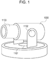
- Reference numeral 1000 in Fig. 1 is a diagram illustrating a monitoring camera according to an embodiment of the present invention.
- Reference numeral 1101 denotes a panning mechanism which pans the lens direction of the monitoring camera 1000.
- Reference numeral 1102 denotes a tilting mechanism which tiles the lens direction.
- Reference numeral 1103 denotes a zooming mechanism which changes the zoom power of the lens.
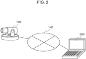
- Fig. 2 is a system configuration diagram including the monitoring camera 1000.
- Reference numeral 2000 denotes a client device, which is the external device in the present embodiment.
- the monitoring camera 1000 and the client device 2000 are communicably connected to each other over an IP network 1500.
- the client device 2000 transmits to the monitoring camera 1000 various types of commands, such as later-described changes to imaging parameters, and instructions for driving of a camera platform, starting video streaming, and so forth.
- the monitoring camera 1000 transmits responses to the commands and streaming video to the client device 2000.
- Fig. 3 is a block diagram illustrating the internal configuration of the monitoring camera 1000.
- Reference numeral 1001 denotes a control unit which centrally controls the components making up the monitoring camera 1000.
- Reference numeral 1002 denotes a storage unit.
- the storage unit 1002 is primarily used as a storage region for various types of data, such as a storage region for programs which the control unit 1001 executes, a work region for programs being executed, a storage region for image data which a later-described imaging unit 1003 generates, and so forth.
- Reference numeral 1003 denotes an imaging unit. This imaging unit 1003 converts analog images obtained by shooting a subject into digital data, and outputs to the storage unit 1002 as an imaged image.
- the imaging unit 1003 supports multiple VideoSourceModes to change resolution of image data to be output, frame rate, and compression encoding format which can be used. These VideoSourceModes can be switched by a later-described SetVideoSourceMode command.
- Reference numeral 1004 denotes a compression encoding unit.
- the compression encoding unit 1004 generates image data by performing compression encoding processing as to an imaged image output from the imaging unit 1003, based on a format such as JPEG or H.264 or the like, and outputs to the storage unit 1002.
- There is a dependency relationship such as illustrated in Fig. 5 which will be described later, between the types of resolution of image data which the compression encoding unit 1004 outputs and the modes of the imaging unit 1003.
- Reference numeral 1005 denotes a communication unit. This communication unit 1005 is used in cases of receiving control commands from an external device, and in cases of transmitting responses as to the control commands to the external device.
- Reference numeral 1006 denotes an imaging control unit.
- the imaging control unit 1006 is used to control the tilting mechanism 1101, panning mechanism 1102, and zooming mechanism 1003, based on pan angle, tilt angle, and zoom power values input from the control unit 1001.
- the imaging control unit 1006 also provides the current pan angle value, tilt angle value, and zoom power value of the monitoring camera 1000, in response to inquiry from the control unit 1001.
- FIG. 2 While an internal configuration of the monitoring camera 1000 has been described with reference to Fig. 2 , the processing blocks illustrated in Fig. 2 are only illustrate an example of a preferred embodiment of a security camera according to the present invention, and are not restrictive. Various modifications and alterations may be made within the scope of the essence of the present information, such as providing an audio input unit, omitting the imaging control unit, and so forth.
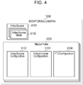
- Fig. 4 illustrates the structure of parameters which the monitoring camera 1000 according to the present embodiment holds.
- a MediaProfile 6100 is a parameter set for storing setting items for the monitoring camera in a correlated manner.
- the MediaProfile 6100 includes a Profile Token which is the ID of the MediaProfile 6100, a VideoSourceConfiguration 6102, and a VideoEncoderConfiguration 6103.
- the MediaProfile 6100 also holds a PTZConfiguration 6104, and further links to various types of setting items, including audio encoders and so forth. That is to say, these links correlate the MediaProfile 6100 to the PTZConfiguration 6104 and also to various types of setting items, including audio encoders and so forth.
- VideoSource 6101 is a set of parameters indicating capabilities of one imaging unit 1003 which the monitoring camera 1000 includes.
- This VideoSource 6101 includes a VideoSourceToken which is the ID of the VideoSource 6101, and a Resolution indicating the resolution of image data which the imaging unit 1003 is capable of outputting.
- Resolution in the present embodiment corresponds to resolution settings.
- the VideoSource 6101 also supports multiple of VideoSourceMode 6105 including the maximum resolution of image data which the imaging unit 1003 is capable of outputting, frame rate, and available compression encoding format. That is to say, a VideoSource 6101 is correlated with one of the multiple VideoSourceMode 6105.
- VideoSourceMode correlated with the VideoSource 6101 can be switched by a SetVideoSourceMode command.
- This VideoSourceMode 6105 will be described later. Note that hereinafter, VideoSourceMode may be abbreviated to VSM.
- the VideoSourceConfiguration 6102 is a set of parameters correlating the VideoSource 6101 of the monitoring camera 1000 with the MediaProfile 6100.
- the VideoSourceConfiguration 6102 includes Bounds, which is data to specify which part of image data output from the VideoSource 6101 is to be cut out and used as distribution images.
- the VideoEncoderConfiguration 6103 is a set of parameters correlating encoder settings relating to compression encoding of image data to the MediaProfile 6100.
- the imaging unit 1003 in monitoring camera 1000 outputs image data based on the VideoSource 6101 and the VideoSourceConfiguration 6102.
- the output image data is subjected to compression encoding following parameters such as the compression encoding format set to this VideoEncoderConfiguration 6103 (e.g., JPEG or H.264), frame rate, resolution, or the like.
- the image data thus compression-encoded is distributed to client devices 2000 via the communication unit 1005.
- the VideoEncoderConfiguration 6103 includes a VideoEncoderConfigurationToken which is the ID of the VideoEncoderConfiguration 6103.
- the VideoEncoderConfiguration 6103 also includes Encoding for specifying a compression encoding format, and Resolution for specifying the resolution of the output image from the monitoring camera 1000. Note that Encoding in the present embodiment corresponds to compression encoding format settings.
- VideoEncoderConfiguration 6103 includes Quality for specifying the compression encoding quality, and FramerateLimit for specifying the maximum frame rate of the output images from the monitoring camera 100. Moreover, the VideoEncorderConfiguration 6103 includes a BitrateLimit for specifying the maximum bitrate.
- VideoEncoderConfiguration may be abbreviated to VEC.
- the PTZConfiguration 6104 is a set of parameters correlating the settings relating to the panning mechanism 1101, tilting mechanism 1102, and zooming mechanism 1103 of the monitoring camera 1000, with the MediaProfile 6100.
- the PTZConfiguration 6104 includes information relating to a coordinates system representing the actual pan/tilt angle values and zoom power value of the panning mechanism, tilting mechanism, and zooming mechanism.
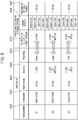
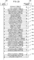
- Fig. 5 is a table to describe the dependency relationship between the imaging unit 1003 and the compression encoding unit 1004.
- the table illustrated in Fig. 5 is stored in the storage unit 1002 in the monitoring camera 100 beforehand, and is referenced by the control unit 1001 as needed.
- Reference numeral 4000 in Fig. 5 denotes the mode No. of the VSM which the monitoring camera 1000 uses for internal processing.
- the monitoring camera 1000 according to the present embodiment supports three VSMs, namely S1, S2, and S3. That is to say, the monitoring camera 1000 holds these three VSMs in the storage unit 1002.
- Reference numeral 4001 denotes a MaxResolution parameter representing the greatest resolution which the imaging unit 1003 can output in each VSM.
- Reference numeral 4002 denotes a MaxFramerate parameter which represents the greatest frame rate which the imaging unit 1003 can output in each VSM.
- Reference numeral 4003 denotes an Encoding parameter representing the compression encoding formats available for the VEC in each VSM.
- Reference numeral 4004 denotes a RebootFlag parameter representing whether or not the imaging unit 1003 needs to be restarted at the time of switching to each VSM.
- the VSMs include an Enables flag.
- the Enabled flag of a valid VSM currently set to the imaging unit 1003 is set to True, and the value of the other Enabled flags is set to False.
- Reference numerals 4005 through 4007 indicate the settable ranges and options for the parameters of the VEC 6103 which can be set thereto from an external device by the SetVideoEncoderConfiguration command, for each VSM.
- Reference numeral 4005 denotes compression encoding format options. For example, this indicates that in a case where the VSM is S1, this shows that only H.264 is selectable as a compression encoding format.
- Reference numeral 4006 denotes options for Resolution, which is the resolution of the VEC. This settings value determines the resolution of the distribution image which the compression encoding unit 1004 outputs. For example, this indicates that in a case where the VSM is S2, the resolutions of 3200 ⁇ 2400, 2048 ⁇ 1536, 1024 ⁇ 768, and 640 ⁇ 480 are selectable.
- Reference numeral 4007 denotes the settable range for the FramerateLimit of the VEC. For example, this indicates that in a case where the VideoSourceMode is S3, the settable FramerateLimit is 1 to 30 fps.
- Fig. 6 illustrates a typical command sequence between the monitoring camera 1000 and client device 2000, from start of setting to video distribution.
- transaction means the pair of a command transmitted from the client device 2000 to the monitoring camera 1000, and a response returned from the monitoring camera 1000 to the client device 2000.
- Reference numeral 7098 denotes a network subscription notification event.
- the monitoring camera 1000 transmits this event to the network by multicasting, to indicate that it is now capable of receiving commands, to external devices connected to this network.
- Reference numeral 7099 denotes a GetServiceCapabilities command transaction.
- the GetServiceCapabilities command is a command instructing the monitoring camera 1000 to return capabilities information indicating the capabilities which the monitoring camera 1000 supports.
- This capabilities information includes information indicating whether or not the monitoring camera 1000 is compatible with VSM switching.
- Reference numeral 7100 denotes a GetVideoSourceConfigurations command transaction.
- the client device 2000 uses this command to obtain a VideoSourceConfiguration 6102 list which the monitoring camera 1000 holds.
- Reference numeral 7101 denotes a GetVideoEncoderConfigurations command transaction.
- the client device 2000 uses this command to obtain a VEC 6103 list which the monitoring camera 1000 holds.
- Reference numeral 7102 denotes a GetConfigurations command transaction.
- the client device 2000 uses this command to obtain a PTZConfiguration 6104 list which the monitoring camera 1000 holds.
- Reference numeral 7103 denotes a CreateProfile command transaction.
- the client device 2000 uses this command to create a new MediaProfile 6100 for the monitoring camera 1000, and obtains a ProfileToken thereof.
- the monitoring camera 1000 After processing of these commands, the monitoring camera 1000 transmits a MediaProfile change notification event, to notify client devices on the network that there has been some sort of change to the MediaProfile.
- Reference numeral 7104 denotes an AddVideoSourceConfigruation command transaction.
- Reference numeral 7105 denotes an AddVideoEncoderConfigruation command transaction.
- Reference numeral 7109 denotes an AddPTZConfiguration command transaction.
- Specifying IDs in these commands enables the client device 2000 to correlate the desired VideoSourceConfiguration, VEC, and PTZConfiguration, with the MediaProfile specified by this ID.
- the monitoring camera 1000 After processing of these commands, the monitoring camera 1000 transmits a MediaProfile change notification event, to notify client devices on the network that there has been some sort of change to the MediaProfile.
- Reference numeral 7106 denotes a GetVideoEncoderConfigurationOptions command transaction. This command enables the client device 2000 to obtain options and settable value ranges of the parameters which the monitoring camera 1000 can accept in the VEC specified by the ID.
- Reference numeral 7107 denotes a SetVideoEncoderConfiguration command transaction.
- the client device 2000 uses this command to set the parameters of the VideoEncoderConfiguration 6103.
- the monitoring camera 1000 transmits a VEC change notification event, to notify client devices on the network that there has been some sort of change to the VEC.
- Reference numeral 7110 denotes a GetStreamUri command transaction.
- the client device 2000 uses this command to obtain an address (URI) for the monitoring camera 1000 to obtain a distribution stream based on the settings of the specified MediaProfile.
- URI address
- Reference numeral 7111 denotes a Describe command transaction.
- the client device 2000 executes this command using the URI obtained in 7110 to request and obtain information regarding the contents of which the monitoring camera 1000 performs streaming distribution.
- Reference numeral 7112 denotes a Setup command transaction.
- the client device 2000 executes this command using the URI obtained in 7110, whereby the monitoring camera 1000 and client device 2000 can share the stream transmission method including session Nos. therebetween.
- Reference numeral 7113 denotes a Play command transaction.
- the client device 2000 executes this command using the session No. obtained in 7112 to request the monitoring camera 1000 to start the stream.
- Reference numeral 7114 denotes a distribution stream.
- the monitoring camera 1000 distributes the stream of which starting has been requested in 7113 by the transmission method shared in 7112.
- Reference numeral 7115 denotes a Teardown command transaction.
- the client device 2000 requests the monitoring camera 1000 to stop the stream, by executing this command using the session No. obtained in 7112.
- Reference numeral 7116 denotes a network breakoff notification event.
- the monitoring camera 1000 transmits this event to the network by multicasting, to indicate that it is now incapable of receiving commands, to external devices connected to this network.
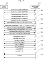
- Fig. 7 illustrates a typical command sequence carried out between the monitoring camera 1000 and client device 2000, in a case performing a VSM mode change which does not involve restarting.
- Reference numeral 7200 denotes a GetServiceCapabilities command transaction.
- the GetServiceCapabilities command is a command instructing the monitoring camera 1000 to return capabilities information indicating the capabilities which the monitoring camera 1000 supports.
- the capabilities information includes information indicating whether or not the monitoring camera 1000 is compatible with VSM switching.
- Reference numeral 7201 denotes a GetVideoSourceMode command transaction.
- the GetVideoSourceMode command is a command instructing the monitoring camera 1000 to return list of VSMs supported by the VideoSource 6101 having the ID which the client device 2000 has specified.
- the client device 2000 uses this command to obtain the VSMs which the monitoring camera 1000 supports.
- the control unit 1001 of the monitoring camera 1000 Upon receiving the GetVideoSourceMode command, the control unit 1001 of the monitoring camera 1000 obtains the parameters of each of the VSMs S1 through S3 illustrated in Fig. 5 , that are saved in the storage unit 1002, and returns these to the client device 2000 via the communication unit 1005.
- Reference numeral 7202 denotes a SetVideoSourceMode command transaction.
- the SetVideoSourceMode command is a command instructing the monitoring camera 1000 to switch the VSM of the VideoSource6101 specified by the client device 2000.
- the control unit 1001 of the monitoring camera 1000 transmits a VSM change notification event to notify the client devices on the network of the VSM change.
- Reference numeral 7203 denotes processing of updating inconsistency occurring between the VideoSourceMode and VEC by switching of the SetVideoSourceMode illustrated in 7202.
- the control unit 1001 of the monitoring camera 1000 transmits a VEC change notification event, and notifies the client devices on the network of the VEC settings values and re-obtaining of settings value options of the VEC.
- Reference numerals 7204 and 7205 denote GetVideoEncoderConfigurationOptions command and GetVideoEncoderConfigurations command transactions.
- the client device 2000 which has received the VEC change notification event illustrated in 7203 obtains the updated VEC settings values and the VEC settings value options, using these commands.
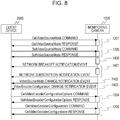
- Fig. 8 illustrates a typical command sequence carried out between the monitoring camera 1000 and client device 2000, in a case performing a VSM mode change which involves restarting.
- Fig. 8 is the same as Fig. 7 regarding portions of 7201 and earlier, and 7204 and later.
- Reference numeral 7399 denotes a SetVideoSourceMode command transaction for a VSM change needing restarting. In this case, the monitoring camera 1000 does not transmit the VSM change notification event at this timing.
- Reference numeral 7400 denotes processing of updating inconsistency occurring between the VSM and VEC by switching of the SetVideoSourceMode illustrated in 7399. In this case, the monitoring camera 1000 does not transmit the VEC change notification event at this timing.
- Reference numeral 7401 denotes restarting processing of the monitoring camera 1000.
- the monitoring camera 1000 transmits a network breakoff notification event, performs restarting processing and transmits a network subscription notification event.
- Reference numerals 7402 and 7403 denote a VSM change notification event and a VEC change notification event.
- the monitoring camera 1000 transmits these events after restarting, and prompts the client device 1000 to re-obtain the settings values.
- Fig. 13 illustrates a case of the monitoring camera 1000 receiving the SetVideoSourceMode command from the client device 2000.
- the control unit 1001 starts this processing.
- the control unit 1001 does not start this processing.
- step S1000 the control unit 1001 stops the video stream being distributed, via the communication unit 1005.
- step S1001 the control unit 1001 distinguishes which of S1 through S3 of the VSM which has been input is, obtains settings values of the relevant VSM from the storage unit 1002, and sets the obtained VSM settings values to the imaging unit 1003.
- the control unit 1001 first reads out, from the storage unit 1002, the settings values of the VSM specified in the SetVideoSourceMode command received from the client device 2000, and sets the settings values which have been read out to the imaging unit 1003.
- step S1002 the control unit 1001 sets the Enable flag corresponding to the VSM distinguished in step S1001 to True, and sets the Enable flags corresponding to the other VSMs to False.
- step S1003 the control unit 1001 transmits a normal response to the client device 2000.
- step S1004 the control unit 1001 references the RebootFlag of the VSM regarding which the settings values have been set in step S1001, and determines whether or not the VSM has been switched to a VSM necessitating restarting. In a case where determination is made that restarting is necessary, the control unit 1001 advances the flow to step S1020, and in a case where determination is made that restarting is not necessary, to step S1005.
- step S1005 the control unit 1001 transmits a VSM change notification event via the communication unit 1005, so as to notify the client device 2000 on the network of the VSM change.
- step S1020 the control unit 1001 sets a VSM change notification event transmission flag to ON.
- the control unit 1001 references this flag in later-described restarting processing.
- step S1021 the control unit 1001 sets the restarting start flag to ON.
- the control unit 1001 references this flag after processing of the commands has ended, and in a case where the flag is ON, the control unit 1001 executes restarting processing following processing of the commands.
- step S1006 the control unit 1001 references the table illustrated in Fig. 5 , which is stored in the storage unit 1003, and determines consistency between information set to all VECs that are stored, and the options 4005, 4006, and 4007 of VECs corresponding to the current VSM.
- This information here is compression encoding format Encoding, resolution, and maximum frame rate FramerateLimit.
- control unit 1001 advances the flow to S1007, and otherwise ends the processing of this command.
- step S1007 the control unit 1001 changes the parameters of the VEC regarding which there has been the inconsistency in step S1006, to contents which are consistent.
- Various implementations are conceivable for the method of changing.
- the Encoding in the VideoEncorderConfiguration may be changed from JPEG to H.264. Also, in a case where the VSM is changed from S3 to S1 at this time, the Resolution in the VideoEncorderConfiguration may be changed from 320 ⁇ 240 to 960 ⁇ 540.
- the FramerateLimit in the VideoEncorderConfiguration may be changed from 25 fps to 20 fps.
- change may be made to that at the top of a list of Encoding consistent with the new VSM.
- step S1008 the control unit 1001 determines whether or not the new VSM suggests necessitating restarting. In a case where restarting is unnecessary, the flow advances to step S1009, and in a case where restarting is necessary, the flow advances to step S1030.
- step S1009 the control unit 1001 transmits a VEC change notification event via the communication unit 1005, so as to notify the client devices on the network of the VEC change.
- step S1020 the control unit 1001 sets a VEC change notification event transmission flag to ON.
- the control unit 1001 references this flag in later-described restarting processing.
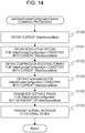
- Fig. 14 illustrates processing in a case where the monitoring camera 1000 has received the above-described GetVideoEncoderConfigurationOptions command from the client device 2000.
- step S1100 the control unit 1001 distinguishes which of S1 through S3 the VSM set to the current VideoSource 6101 is, by referencing the Enable flag.
- control unit 1001 references the table in Fig. 5 that is stored in the storage unit 1002, and obtains the options of the compression encoding formats Encoding, consistent with the current VSM.
- the control unit 1001 also references the table in Fig. 5 that is stored in the storage unit 1002, and obtains the options of the resolution of the VEC, and the options of the maximum frame rate FramerateLimit, consistent with the current VSM.
- the current VSM is S3, H.264 and JPEG are obtained as options for the compression encoding format Encoding, and 1024 ⁇ 768, 640 ⁇ 480, 320 ⁇ 240, and 176 ⁇ 144 as options for Resolution. Also, in a case where the current VSM is S3, 1 to 30 fps is obtained as the FramerateLimit.
- step S1104 the control unit 1001 obtains options and setting ranges of a VEC not dependent on the current VSM, from the storage unit 1002. For example, 1 to 5 is obtained as a settable range for Quality, and 1 to 60 Mbps as the BitrateLimit.
- step S1105 the control unit 1001 includes the options and setting ranges obtained in step S1101 through step S1104 in a normal response, and returns this to the client device 2000 via the communication unit 1005.
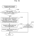
- Fig. 15 illustrates processing in a case where the monitoring camera 1000 has received the above-described SetVideoEncoderConfiguration command from the client device 2000.
- step S1200 the control unit 1001 references the table illustrated in Fig. 4 , which is stored in the storage unit 1003, and determines whether or not information input in the SetVEC received by this command is consistent with the current VSM.
- This information is the resolution Resolution, compression encoding format Encoding, and FramerateLimit.
- control unit 1001 advances the flow to step S1210.
- step S1201 the control unit 1001 stores the settings values of the VEC recepved by this command in the storage unit 1002, and sets to the compression encoding unit 1004.
- this command includes Quality, Quality, BitrateLimit, Encoding, FramerateLimit, and Resolution.
- step S1202 the control unit 1001 transmits a normal response to the client device 2000.
- step S1203 the control unit 1001 transmits a VEC change notification event via the communication unit 1005, so as to notify the VEC change to the client devices on the network.
- step S1210 the control unit 1001 transmits an error response to the client device 200.
- Fig. 16 is restarting processing. This processing is processing executed by the control unit 1001 in a case where the restarting start flag is ON immediately after reception processing of the commands.
- step S1700 the control unit 1001 transmits a network breakoff notification event via the communication unit 1005, so as to notify starting of restarting to the client devices on the network.
- step S1701 the control unit 1001 performs the actual restarting processing of the monitoring camera 1000.
- step S1702 the control unit 1001 transmits a network subscription notification event via the communication unit 1005, so as to notify completion of restarting to the client devices on the network.
- step S1703 the control unit 1001 determines the VEC change notification transmission flag. If ON, the flow advances to step S1704.
- step S1704 the control unit 1001 transmits a VEC change notification event via the communication unit 1005, so as to notify the VEC change to the client devices on the network.
- step S1705 the control unit 1001 determines the VSM change notification transmission flag. If ON, the flow advances to step S1706.
- step S1706 the control unit 1001 transmits a VSM change notification event via the communication unit 1005, so as to notify the VSM change to the client devices on the network.
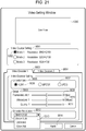
- Fig. 21 illustrates a setting screen suitable for the client device 2000 performing settings of the VSM and VEC of the monitoring camera 1000 described according to the present embodiment.
- Reference numeral 9000 denotes a Live View area.
- the client device 2000 executes the sequence illustrated in Fig. 6 described above, and displays the video stream obtained in the transaction 7113 in the Live View area.
- Reference numeral 9001 denotes a VSM selection area.
- the client device 2000 determines whether or not the monitoring camera 1000 is compatible with VSM switching, by the GetServiceCapabilities transaction 7099 executed in conjunction with opening this setting scree. If compatible, the VSMs obtained by the GetVideoSourceMode transaction 7200 are listed in this area so that the user can select one, as indicated by 9002. Upon a VSM different from that currently set is selected in this area, the client device 2000 executes the SetVideoSourceMode command to change the VSM of the monitoring camera 1000.
- the client device 2000 executes the transaction illustrated in Fig. 7 described above, and a video stream according to the new settings is displayed on the Live View area 9000.
- the client device 2000 uses the results obtained by the GetVideoEncoderConfigurationOptions command in the transaction in Fig. 7 to update the options and setting ranges of the parameters for Video Encoder in this screen.
- the client device 2000 can thus constantly provide the user with options and setting ranges for the VEC settings values which are consistent with the VSM.
- Reference numerals 9003 and 9004 denote tabs to switch the Video Encoding setting screen, so that the user can change the settings values of the VEC 6103 of the monitoring camera 1000. While the number of tabs is two in this example, an arrangement may be made where as many are displayed as the number of VECs 6103, obtained by the GetVideoEncoderConfigurations command, which the monitoring camera 1000 supports.
- Reference numeral 9005 denotes an area for the user to select the compression encoding format of each VEC.
- the options are displayed for the compression encoding format Encoding obtained by the GetVideoEncoderConfigurationOptions included in the transaction in Fig. 6 when this setting screen is opened.
- the options are displayed for the compression encoding format Encording obtained by the GetVideoEncoderConfigurationOptions command included in the transaction in Fig. 7 when a new VSM is selected in the VSM selection area.
- Reference numeral 9006 denotes currently selectable Encodring
- 9007 denotes currently non-selectable Encording
- Reference numeral 9008 denotes a Detail area for selecting the FramerateLimit, BitrateLimit, and Quality, included in the VEC 6103.
- Setting ranges 9009, 9010, and 9011 reflect the setting ranges each obtained by the GetVideoEncoderConfigurationOptions command included in Fig. 6 when this setting screen is opened.
- these setting ranges reflect the setting ranges each obtained by the GetVideoEncoderConfigurationOptions command included in the transaction in Fig. 7 when a new VSM is selected in the VSM selection area.
- Reference numeral 9012 denotes an area for selecting the resolution Resolution of the VEC 6103.
- the drop-down list 9013 displays the contents of options of the Resolution parameter obtained by the GetVideoEncoderConfigurationOptions included in the transaction in Fig. 6 when this setting screen is opened.
- the drop-down list 9013 displays the contents of options of the Resolution parameter obtained by the GetVideoEncoderConfigurationOptions command included in the transaction in Fig. 7 when a new VSM is selected in the VSM selection area.
- Reference numeral 9014 denotes an Apply button. Upon the user pressing this button, the client device 2000 transmits the SetVideoEncoderConfiguration to the monitoring camera 1000. The parameters selected in 9005, 9008, and 9012 are reflected in the compression encoding unit of the monitoring camera 1000 by this transmission.
- the monitoring camera 1000 performs the following processing. That is processing to update what is in the settings of the VEC, and the options provided by the GetVideoEncoderConfigurationOptions command to those which are consistent with the VSM.
- the monitoring camera 1000 prompts re-obtaining the contents of the VEC regardless of whether the new VSM necessitates restarting or not. This is to prevent occurrence of inconsistency in the setting values and settable ranges for the imaging unit and compression encoding unit, between the monitoring camera 1000 and the client device 2000. That is to say, even in a case where the resolution of the image data which the imaging unit generates is changed, inconsistency in the various settings including the resolution of the distribution image which the compression encoding unit generates can be prevented from occurring, so generating of distribution images after changing the resolution, and further changes to settings values, can be easily performed.
- the first embodiment describes the types of options of resolution for the compression encoding unit provided by the GetVideoEncoderConfigurationOptions command to be restricted to those consistent with the VSM, this is not restrictive.
- An arrangement may be made where options for all resolutions are provided to the client device at all times by the GetVideoEncoderConfigurationOptions command.
- the following processing may then be performed along with new settings values of the compression encoding unit set by the client device 2000 using the SetVideoEncoderConfiguration command.
- the monitoring camera 1000 may be configured to internally switch the VSM to a mode compatible therewith, and transmit a notification to the client device 2000 to prompt re-obtaining the updated VSM contents.
- Reference numeral 1000 in Fig. 1 is a diagram illustrating a monitoring camera according to one embodiment of the present invention.
- Fig. 2 is a system configuration diagram including the monitoring camera 1000.
- Fig. 3 is a diagram illustrating the internal configuration of the monitoring camera 1000.
- Fig. 4 is a diagram illustrating the structure of parameters which the monitoring camera 1000 according to the present embodiment holds.
- the table in Fig. 5 illustrates the VSMs which the monitoring camera 1000 supports, and the contents of the settable ranges of the VECs 6103 consistent with each VSM.
- Fig. 6 illustrates a typical command sequence carried out between the monitoring camera 1000 and the client device 2000, from start of setting to video distribution.
- Fig. 9 illustrates a typical command sequence carried out between the monitoring camera 1000 and the client device 2000, in a case of changing the output resolution of the compression encoding unit 1004.
- Reference numeral 7300 denotes processing to update the VSM, to resolve inconsistency between the VSM and VEC which has occurred due to changing the settings of the VEC as indicated by 7107.
- the control unit 1001 of the monitoring camera 1000 transmits a VSM change notification event, to notify the client devices on the network to re-obtain the VSM.
- Reference numerals 7301 and 7302 denote GetVideoEncoderConfigurationOptions command and GetVideoEncoderConfigurations command transactions.
- the client device 2000 which has received the VEC change notification event indicated by 7107 obtains the updated VEC settings values and VEC settings value options by these commands.
- Reference numeral 7303 denotes a GetVideoSourceMode command transaction.
- the client device 2000 which has received the VSM change notification event indicated in 7300 can confirm updating of the VSM by referencing the Enable flag included in the updated VSM by this transaction.
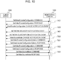
- Fig. 10 illustrates a typical command sequence carried out between the monitoring camera 1000 and the client device 2000, in a case of changing the output resolution of the compression encoding unit 1004, and in which a VSM update occurs which involves restarting.
- Fig. 10 is the same as Fig. 9 regarding portions of 7107 and earlier, and 7301 and later.
- Reference numeral 7500 denotes processing to update the VSM, so as to resolve inconsistency between the VSM and VEC which has occurred due to changing the settings of the VEC as indicated by 7107.
- the monitoring camera 1000 does not transmit the VSM change notification event.
- Reference numeral 7502 denotes a VSM change notification event.
- the monitoring camera 1000 transmits this event after restarting, and prompts the client device 1000 to re-obtain the settings values.
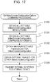
- Fig. 17 illustrates processing in a case of the monitoring camera 1000 having received a GetVideoSourceConfigurationOptions command from the client device 2000.
- step S1300 the control unit 1001 references the table illustrated in Fig. 4 , stored in the storage unit 1002, and obtains resolution options for all VECs which can be assumed, regardless of the VSM.
- step S1301 the control unit 1001 references the table illustrated in Fig. 4 , stored in the storage unit 1002, and obtains compression encoding format options for all VECs which can be assumed, i.e., JPEG, MEPG4, and H.264.
- step S1302 the control unit 1001 references the table illustrated in Fig. 4 , stored in the storage unit 1002, and obtains the greatest value of FramerateLimit of all VECs which can be assumed, which is 30 fps.
- step S1303 the control unit 1001 obtains options and setting ranges for VECs not dependent on the current VSM, from the storage unit 1002. For example, 1 to 5 is selected as a settable range for Quality, and 60 Mbps is obtained as a settings value for BitrateLimit.
- step S1304 the control unit 1001 includes the options and setting ranges obtained in step S1300 through step S1303 in a normal response, and returns this to the client device 2000 via the communication unit 1005.
- Fig. 18 illustrates processing in a case where the monitoring camera 1000 has received the above-described SetVideoEncoderConfiguration command from the client device 2000.
- Steps S1201 through S1203 are as described above.
- step S1400 the control unit 1001 references the table illustrated in Fig. 5 , which is stored in the storage unit 1003, and determines whether or not information set in the received VEC received by this command is consistent with the current VSM.
- This information is the compression encoding format Encoding, resolution Resolution, and maximum frame rate FramerateLimit.
- control unit 1001 advances the flow to step S1410.
- step S1410 the control unit 1001 references the table illustrated in Fig. 4 , stored in the storage unit 1003, and switches the current VSM to a VSM consistent with the VEC input in this command.
- the VSM is S1 and the Resolution is input to this command as 640 ⁇ 480 for example, the VSM is switched to S3 which is consistent with this resolution.
- step S1411 the control unit 1001 references the RebootFlag of the VSM that has been set, and determines whether or not change has been made to a VSM which necessitates restarting. If restarting is necessary, the control unit 1001 advances the flow to step S1010, and if restarting is not necessary, to step S1005.
- step S1412 the control unit 1001 transmits a VSM change notification event via the communication unit 1005, so as to notify the client devices on the network of the VSM change.
- step S1411 the control unit 1001 references the RebootFlag of the VSM that has been updated, and determines whether or not change has been made to a VSM which necessitates restarting. If restarting is necessary, the control unit 1001 advances the flow to step S1420, and if restarting is not necessary, to step S1412.
- step S1412 the control unit 1001 transmits a VSM change notification event via the communication unit 1005, so as to notify the client devices on the network of the VSM change.
- step S1420 the control unit 1001 sets the VSM change notification event transmission flag to ON.
- step S1421 the control unit 1001 sets the restarting start flag to ON.
- Fig. 16 illustrates details of restarting processing.
- Fig. 21 illustrates a setting screen suitable for the client device 2000 performing settings of the VSM and VEC of the monitoring camera 1000 described according to the present embodiment.
- Reference numeral 9012 denotes an area for selecting the resolution Resolution of the VEC 6103.
- the drop-down list 9013 displays the contents of options of the Resolution parameter obtained by the GetVideoEncoderConfigurationOptions executed when this setting screen is opened.
- the monitoring camera 1000 according to the present embodiment provides all resolutions obtained from the table in Fig. 5 as options, so as a result, the drop-down list 9013 displays all resolutions.
- the client device 2000 In a case of having received a VSM change notification event transmitted in Fig. 18 or Fig. 16 , the client device 2000 references the Enable flag obtained by the GetVideoSourceMode command. The client device 2000 determines the updated and valid VSM by making this reference, and reflects this in the VSM selection area 9001.
- the monitoring camera 1000 provides the setting contents of all VECs which can be assumed as options, regardless of the current VSM, and provides these to the client device 2000.
- a VEC parameter inconsistent with the current VSM has been specified, including the resolution of the compression encoding unit
- updating is internally made to a VSM which is consistent.
- the monitoring camera 1000 prompts re-obtaining the contents of the VSM regardless of whether the new VSM necessitates restarting or not. This is to prevent occurrence of inconsistency in the setting values and settable ranges for the imaging unit and compression encoding unit, between the monitoring camera 1000 and the client device 2000.
- a VSM change notification event and a VEC change notification event have been exemplarily illustrated as methods to prompt the client to re-obtain the VSM and VEC settings values and setting ranges, but this is not restrictive.
- An arrangement may be made where a network breakoff notification event and network subscription notification event are transmitted at a timing at which the client is prompted to re-obtain updated parameters, thereby prompting to re-obtain setting values of the monitoring camera 1000.
- Reference numeral 1000 in Fig. 1 is a diagram illustrating a monitoring camera according to one embodiment of the present invention.
- Fig. 2 is a system configuration diagram including the monitoring camera 1000.
- Fig. 3 is a diagram illustrating the internal configuration of the monitoring camera 1000.
- Fig. 4 is a diagram illustrating the structure of parameters which the monitoring camera 1000 according to the present invention holds.
- the table in Fig. 5 illustrates the VSMs which the monitoring camera 1000 supports, and the contents of the settable ranges of the VECs 6103 consistent with each VSM.
- Fig. 6 illustrates a typical command sequence carried out between the monitoring camera 1000 and the client device 2000, from start of setting to video distribution.
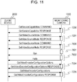
- Fig. 11 illustrates a typical command sequence carried out between the monitoring camera 1000 and the client device 2000, from changing VSM settings to video distribution.
- Fig. 11 is the same as Fig. 7 regarding portions of 7201 and earlier, and 7204 and later.
- Reference numeral 7600 denotes a SetVideoSourceMode command transaction.
- the SetVideoSourceMode command is a command to instruct the VSM of the VideoSource 6101 which the client device 2000 has specified, to be changed.
- Reference numeral 7601 denotes processing to update an inconsistency which has occurred between the VSM and VEC by the switching of the SetVideoSourceMode indicated in 7600.
- Reference numeral 7602 denotes processing in which the control unit 1001 of the monitoring camera 1000 transmits a network breakoff notification event and network subscription notification event, to notify the client devices on the network of the change in VSM and VEC.
- restarting processing of the monitoring camera 1000 may be performed between the network breakoff notification event and network subscription notification event.
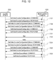
- Fig. 12 illustrates a typical command sequence carried out between the monitoring camera 1000 and the client device 2000, in a case of changing the output resolution of the compression encoding unit 1004.
- Fig. 12 is the same as Fig. 9 regarding portions of 7106 and earlier, and 7301 and later.
- Reference numeral 7700 denotes a SetVideoEncoderConfiguration command transaction. This command causes the client device 2000 to set the parameters of the VideoEncdorConfiguration 6103.
- Reference numeral 7701 denotes processing to update the VSM so as to resolve an inconsistency which has occurred between the VideoSurceMode and VEC by changing the settings of the VEC indicated in 7700.
- Reference numeral 7702 denotes processing in which the control unit 1001 of the monitoring camera 1000 transmits a network breakoff notification event and network subscription notification event, to notify the client devices on the network of the change in VSM and VEC.
- restarting processing of the monitoring camera 1000 may be performed between the network breakoff notification event and network subscription notification event.
- Fig. 17 illustrates processing in a case where the monitoring camera 1000 has received a GetVideoSourceConfigurationOptions command from the client device 2000.
- Fig. 19 illustrates processing in a case where the monitoring camera 1000 has received a SetVideoSource command from the client device 2000.
- S1503 and earlier in this drawing is the same as in Fig. 13 .
- step S1500 the control unit 1001 performs the same determination as in step S1006. In a case where there is even one VEC incompatible with these options, the control unit 1001 advances the flow to S1007, and otherwise advances the flow to S1502.
- step S1502 and step S1505 the control unit 1001 transmits, via the communication unit 1005, a network breakoff notification event and network subscription notification event, to notify the client devices on the network of the changes to the VSM and VEC.
- step S1503 the control unit 1001 references the RebootFlag of the VSM that has been set, and determines whether or not the VSM has been changed to a VSM which necessitates restarting. In a case where restarting is necessary, the control unit 1001 executes step S1701, and if restarting is unnecessary advances the flow to step S1505.
- Fig. 20 illustrates processing in a case where the monitoring camera 1000 has received a SetVideoEncoderConfiguration command from the client device 2000.
- the processing of each step is the same as described above, so description will be omitted.
- Fig. 21 illustrates a setting screen suitable for the client device 2000 performing settings of the VSM and VEC of the monitoring camera 1000 described according to the present embodiment.
- the monitoring camera 1000 updates the other consistent contents. Also, at the time of updating, the monitoring camera 1000 transmits network breakaway and network subscription notification events to the client device 2000 regardless of whether or not restarting is necessary. This is to prevent occurrence of inconsistency in the setting values and settable ranges for the imaging unit and compression encoding unit, between the monitoring camera 1000 and the client device 2000.
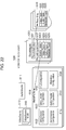
- Fig. 22 illustrates the structure of parameters which the monitoring camera 1000 according to the present embodiment holds.
- the names and contents of the commands, parameters, and so forth, which are used in the present embodiment, will be described below.
- a RecordingJob 6200 is a set of parameters specifying correlation of media data to be recorded as specified by a Profile Token, and Rcording which is a recording destination file specified by a later-described Recording Token. Note that RecordingJob 6200 in the present embodiment corresponds to a recording job.
- a Recording 6300 is a file to record media data correlated by the RecordingJob 6200.
- Data to be recorded is specified from video data, audio data, and metadata, by adding or deleting each of the three tracks of Video Track 6301, Audio Track 6302, and Metadata Track 6303.
- Metadata Track 6304 corresponds to text data.
- the Recording 6300 according to the present embodiment corresponds to a recording file.
- Selection of the Recording 6300 is performed by a Recording Token which is an ID of each Recording.
- the RecordingJob 6200 is made up of a Recording Token which specifies a recording destination file, and a RecordingSource 6202 which specifies metadata for recording. Further, the RecordingJob 6200 is also made up of a Mode to externally instruct start/stop of recording, Priority which indicates priority of recording, and State which indicates the state of recording of video recording.
- RecordingSource 6202 is equivalent to a recording source. Also, State in the present embodiment is equivalent to a recording state.
- the RecordingSource 6202 is made up of a Source Token which specifies the output source of the media data to be recorded by a Profile Token.
- the RecordingSource 6202 further is also made up of a State which indicates whether the RecordingSource 6202 is currently being used for recording, and a Video Track 6204 to select the type of media data to be recorded.
- the RecordingSource 6202 is also made up of an Audio Track 6205 and Metadata Track 6206.
- the Tracks 6204, 6205, and 6206 each hold a State indicate whether currently being used for recording.
- the State of the RecordingSource, and States of Video Track, Audio Track, and Metadata Track, are each indicated by the following. That is, Idle which indicates not being used for recording, Active which indicates that recording is being performed, and Error which indicates that an abnormality has occurred.
- Idle and Error according to the present embodiment correspond to states other than recording being performed.
- Fig. 23 represents a typical command sequence between the monitoring camera 1000 and client device 2000, from starting of settings to performing recording. Settings of the MediaProfile 6100 in the monitoring camera 1000 are assumed to have already been performed in the command sequence in Fig. 6 .
- Reference numeral 7900 denotes a GetServices command transaction.
- the GetServices command is a command which instructs to return capabilities which the monitoring camera 1000 supports, one service at a time.
- Returned information includes information indicating whether or not the monitoring camera 1000 can provide service relating to recording of media data.
- Reference numeral 7901 denotes a GetServicesCapabilities command transaction.
- the GetServicesCapabilities command is a command which instructs to return capabilities information indicating capabilities which the monitoring camera 1000 supports.
- the capabilities information includes information regarding whether or not the monitoring camera 1000 can handle later-described generating/deleting of Recording and generating/deleting of Track, and so forth.
- Reference numeral 7902 denotes a GetEventProperties command transaction.
- the GetEventProperties command is a command which provides the types of event notifications which the monitoring camera 1000 supports.
- Reference numeral 7903 denotes a Subscribe command transaction.
- the Subscribe command is a command which instructs distribution of an event which the monitoring camera 1000 supports.
- the client device 2000 executes the Subscribe command beforehand, and thus can receive later-described TrackCreation events and ConfigurationChange events from the monitoring camera 1000.
- Reference numeral 7904 denotes a GetReoordings command transaction.
- the GetRecordings command is a command to return a list of Recording 6300 which the monitoring camera 1000 holds.
- the monitoring camera 1000 returns a Recording Token for all Recording 6300 saved in the storage unit 1002.
- Reference numeral 7905 denotes a CreateRecordings command transaction.
- the CreateRecordings command is a command instructing the monitoring camera 1000 to create a new Recording 6300.
- the monitoring camera 1000 Upon creating a new Recording, the monitoring camera 1000 transmits a RecordingsCreation event.
- Reference numeral 7906 denotes a CreateTracks command transaction.
- the CreateTracks command is a command which gives the following instructions regarding a specified Recording 6300 of the monitoring camera 1000. That is, a Video Track 6301, Audio Track 6302, or Metadata Track 6303, is to be created as necessary.
- the monitoring camera 1000 Upon a new Track being created, the monitoring camera 1000 transmits a TrackCreation event.
- Reference numeral 7907 denotes a SetTrackConfiguration command transaction.
- the settings values of Track of a specified Recording 6300 can be changed by the SetTrackConfiguration command.
- Reference numeral 7908 denotes a GetRecordingJobs command transaction.
- the GetRecordingJobs command is a command to return a list of RecordingJob 6200 which the monitoring camera 1000 holds.
- the monitoring camera 1000 returns a list of all RecordingJob 6200 saved in the storage unit 1002.
- Reference numeral 7909 denotes a CreateRecordingJob command transaction.
- the CreateRecordingJob command is a command to cause the monitoring camera 1000 to create a new RecordingJob 6200.
- Reference numeral 7910 denotes a SetRecordingJobConfiguration command transaction.
- the settings values of a specified RecordingJob 6200 can be changed by the SetRecordingJobConfiguration command.
- Reference numeral 7911 denotes a SetRecordingJobConfiguration command transaction.
- the settings values of a specified RecordingJob 6200 can be changed by the SetRecordingJobConfiguration command.
- Reference numerals 7912 and 7913 denote SetRecordingJobMode command transactions.
- a SetRecordingJobMode command is a command which instructs the monitoring camera 1000 to start or stop recording, but switching the mode of a specified RecordingJob. For example, in a case where Mode is changed to Active in 7912, and Modeo is changed to Idle in 7913, recording between 7912 and 7913 will be performed following the settings values of the current RecordingJob 6200. While recording is being performed, the State of the RecordingJob 6200 is Active, and when recording ends becomes Idle.
- Reference numeral 7930 denotes a SetVideoSourceMode command transaction. Details of processing of this command will be described in Fig. 24 .
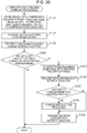
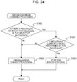
- Fig. 24 illustrates processing in a case of the monitoring camera 1000 having received the SetVideoSourceMode command from the client device 2000.
- step S1800 the control unit 1001 determines whether or not there exists a RecordingJob 6200 of which a VideoSource 6101 subject to a SetVideoSourceMode command is the object of recording.
- control unit 1001 determines whether or not a RecordingJob 6200 such as the following exists in the storage unit 1002. That is, a RecordingJob 6200 which has specified a MediaProfile 6100, including a VideoSourceConfiguration 6102 which references the current VideoSource 6101, as the object of recording by a Source Token 6203.
- control unit 1001 determines that there is a possibility that this VideoSource will be used for recording, and advances the flow to step S1801. If such does not exist, the control unit 1001 advances the flow to S1802, and executes VideoSourceMode changing processing.
- This VideoSourceMode changing processing is processing indicated by step S1000 and thereafter in Fig. 13 .
- step S1801 the control unit 1001 determines whether or not recording is currently being performed, regarding all RecordingJob 6200 of which the current VideoSource 6101 is the object of recording. Specifically, whether the State of the RecordingJob 6200 is Active, i.e., recording is being performed, is determined. If recording is being performed for even one, determination is made by the control unit 1001 that VideoSourceMode switching cannot be performed, and in step S1803 an error response is transmitted to the client device 2000 which is the transmission source of the command. In a case where recording is being performed for none, the control unit 1001 advances the flow to step S1802.
- Fig. 25 illustrates processing in a case of the monitoring camera 1000 having received the SetVideoSourceMode command from the client device 2000.
- step S1900 the control unit 1001 determines whether or not there exists a RecordingJob 6200 of which a VideoEncoderConfiguration 6103 subject to a SetVideoEncoderConfiguration command is the object of recording.
- control unit 1001 determines whether or not a RecordingJob 6200 such as the following exists in the storage unit 1002. That is, a RecordingJob 6200 which has specified a MediaProfile 6100, including the current VideoEncoderConfiguration 6103, as the object of recording by a Source Token 6203.
- control unit 1001 determines that there is a possibility that this VideoEncoderConfiguration 6103 will be used for recording, and advances the flow to step S1901. If such does not exist, the control unit 1001 advances the flow to S1902 and performs VideoEncoderConfiguration changing processing.
- This VideoEncoderConfiguration changing processing is processing indicated by step S1200 and thereafter in Fig. 15 .
- step S1901 the control unit 1001 determines whether or not recording is currently being performed, regarding all RecordingJob 6200 of which the current VideoEncoderConfiguration 6103 is the object of recording. Specifically, whether the State of the RecordingJob 6200 is Active, i.e., recording is being performed, is determined. If recording is being performed for even one, determination is made by the control unit 1001 that VideoEncoderConfiguration changing cannot be performed, and in step S1903 an error response is transmitted to the client device 2000 which is the transmission source of the command. In a case where recording is being performed for none, the control unit 1001 advances the flow to step S1902.
- the monitoring camera 1000 is controlled so as to not change a VSM or VEC being used for recording, and to change if not being used for recording. This can prevent recording from being interrupted due to inconsistency vin combination of the two. Moreover, continuous recording of monitoring data can be realized, and also multiple types of recording data are prevented from being included in a single recording data. Accordingly, video recording enabling more suitable playback can be realized.
- whether or not a VSM and VEC change command can be accepted is determined based on the conditions of whether or not a RecordingJob which references a MediaProfile including the VSM and VEC is currently being recorded, but this is not restrictive. Control may be performed such that determination is made regarding whether or not the RecordingJob includes a VideoTrack as data to be recorded, and if VideoTrack is not the object of recording the VSM and VEC may be changeable even if currently recording.
- control may be performed such that the VSM and VEC may be changeable in the following case, even if the VideoTrack is the object of recording and the State of the RecordingJob is Active. This is a case where the State is Idle for a RecordingsSource of which the current MediaProfile is a Source Token. This is also a case where the State is Idle for a VideoTrack of the RecordingsSource of which the current MediaProfile is a Source Token.
- Fig. 22 illustrates the structure of parameters which the monitoring camera 1000 according to the present embodiment holds.
- the names and contents of the commands, parameters, and so forth, which are used in the present embodiment, will be described below.
- An AudioSource6101 is a set of parameters indicating the capabilities of a sound collecting unit which the monitoring camera has, and includes an AudioSourceToken which is the ID of the AudioSource 6111, and a bit length parameter of audio data which the sound collecting unit can output.
- An AudioSourceConfiguration 6112 is a set of parameters correlating the AudioSource 6111 of the monitoring camera with the MediaProfile 6100.
- An AudioEncoderConfiguration 6113 is a set of parameters correlating encoder settings relating to compression encoding of audio data with the MediaProfile 6100.
- the monitoring camera 1000 performs compression encoding of audio data following parameters, such as the compression encoding format (e.g., G.711 or AAC) or bitrate or the like, set in this AudioEncoderConfiguration 6113, and distributes to the client device 2000.
- This audio data is audio data output based on the contents of the AudioSource 6111 and later-described AudioSourceConfiguration 6112.
- recording is performed in Audio Track of Recording 6300 at the point that recording is started.
- the AudioEncoderConfiguration 6113 specifies an AudioEncoderConfiguration Token which is the Id of the AudioEncoderConfiguration 6113.
- the AudioEncoderConfiguration 6113 also specifies Encoding which specifies the compression encoding format, Quality which specifies compression encoding quality, and bitrate of the output audio. AudioEncoderConfiguration may be abbreviated to AEC.
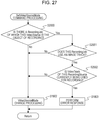
- Reference numeral 7930 denotes a SetVideoSourceMode command transaction in Fig. 23 . Details of this command will be described in Fig. 27 .
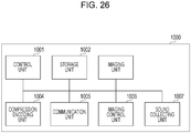
- Fig. 26 is a block diagram illustrating the internal configuration of the monitoring camera 1000.
- reference numeral 1007 denotes a sound collecting unit, and is made up of a microphone, for example.
- the sound collecting unit 1007 digitizes obtained audio and outputs data to the compression encoding unit 1004.
- Reference numeral 1004 denotes the compression encoding unit.
- the compression encoding unit 1004 generates image data by performing compression encoding processing as to data output from the imaging unit 1003, based on a format such as JPEG or H.264 or the like, and outputs to the storage unit 1002.
- the compression encoding unit 1004 also performs compression encoding processing as to data output from the sound collecting unit 1007, based on a format such as G.711 or AAC or the like, and outputs to the storage unit 1002.
- step S2000 the control unit 1001 determines whether or not there exists a RecordingJob 6200 of which a VideoSource 6101 subject to a SetVideoSourceMode command is the object of recording.
- control unit 1001 determines whether or not a RecordingSource 6202 which has specified a MediaProfile 6100 as the object of recording in a Source Token 6203, exists in any RecordingJob 6200.
- this MediaProfile 6100 includes a VideoSourceConfiguration 6102 which references the current VideoSource 6101.
- control unit 1001 determines that there is a possibility that this VideoSource will be used for recording, and advances the flow to step S2001. If such does not exist, the control unit 1001 advances the flow to S1802, and executes VideoSourceMode changing processing.
- This VideoSourceMode changing processing is processing indicated by step S1000 and thereafter in Fig. 13 .
- step S2001 the control unit 1001 determines whether or not any RecordingSource 6202 using the VideoSource found in S2000 includes a VideoTrack. In a case of not including a VideoTrack, the control unit 1001 advances the flow to S1802. If a RecordingSource 6202 including a VideoTrack exists, the control unit 1001 advances the flow to step S2002.
- step S2002 the control unit 1001 determines whether the State of the VideoTrack is Active, i.e., recording is being performed, based on a RecordingSource 6202 such as follows. That is, a RecordingSource 6202 of which the current VideoSource 6101 is the object of recording, and also includes a VideoTrack.
- control unit 1001 determines that VideoSourceMode switching cannot be performed, and in step S1803 an error response is transmitted to the client device 2000 which is the transmission source of the command. In a case where recording is being performed for none, the control unit 1001 advances the flow to step S1802, where VideoSourceMode changing processing is performed.
- the monitoring camera 1000 can accept settings changing of the VSM and VEC in cases that recording of the VideoTrack is not being performed, even in cases where recording is being performed where the VSM or VEC is being referenced by a RecordingJob. Accordingly, continuous recording of monitoring data can be realized while maximally permitting settings changes to the VSM and VEC, and also multiple types of recording data can be prevented from being included in a single recording data. Accordingly, video recording enabling more suitable playback can be realized.
Landscapes
- Engineering & Computer Science (AREA)
- Multimedia (AREA)
- Signal Processing (AREA)
- Studio Devices (AREA)
- Closed-Circuit Television Systems (AREA)
- Television Signal Processing For Recording (AREA)
- Two-Way Televisions, Distribution Of Moving Picture Or The Like (AREA)
Priority Applications (1)
| Application Number | Priority Date | Filing Date | Title |
|---|---|---|---|
| EP18183526.5A EP3422695B1 (en) | 2013-03-15 | 2014-03-14 | Imaging apparatus |
Applications Claiming Priority (2)
| Application Number | Priority Date | Filing Date | Title |
|---|---|---|---|
| JP2013053593A JP6084080B2 (ja) | 2013-03-15 | 2013-03-15 | 撮像装置 |
| PCT/JP2014/056918 WO2014142309A1 (ja) | 2013-03-15 | 2014-03-14 | 撮像装置 |
Related Child Applications (1)
| Application Number | Title | Priority Date | Filing Date |
|---|---|---|---|
| EP18183526.5A Division EP3422695B1 (en) | 2013-03-15 | 2014-03-14 | Imaging apparatus |
Publications (3)
| Publication Number | Publication Date |
|---|---|
| EP2975836A1 EP2975836A1 (en) | 2016-01-20 |
| EP2975836A4 EP2975836A4 (en) | 2016-10-26 |
| EP2975836B1 true EP2975836B1 (en) | 2018-08-01 |
Family
ID=51536956
Family Applications (2)
| Application Number | Title | Priority Date | Filing Date |
|---|---|---|---|
| EP14765747.2A Active EP2975836B1 (en) | 2013-03-15 | 2014-03-14 | Imaging device |
| EP18183526.5A Active EP3422695B1 (en) | 2013-03-15 | 2014-03-14 | Imaging apparatus |
Family Applications After (1)
| Application Number | Title | Priority Date | Filing Date |
|---|---|---|---|
| EP18183526.5A Active EP3422695B1 (en) | 2013-03-15 | 2014-03-14 | Imaging apparatus |
Country Status (8)
| Country | Link |
|---|---|
| US (2) | US9742999B2 (enExample) |
| EP (2) | EP2975836B1 (enExample) |
| JP (1) | JP6084080B2 (enExample) |
| KR (1) | KR101699311B1 (enExample) |
| CN (2) | CN105052128B (enExample) |
| BR (1) | BR112015021275A2 (enExample) |
| RU (1) | RU2613176C1 (enExample) |
| WO (1) | WO2014142309A1 (enExample) |
Families Citing this family (7)
| Publication number | Priority date | Publication date | Assignee | Title |
|---|---|---|---|---|
| KR102537559B1 (ko) | 2016-11-14 | 2023-05-26 | 한화비전 주식회사 | 영상촬영장치에서 다양한뷰모드를 제공하는 방법 |
| JP7022540B2 (ja) * | 2017-09-08 | 2022-02-18 | キヤノン株式会社 | 情報処理装置およびその制御方法 |
| US12108148B2 (en) | 2021-07-05 | 2024-10-01 | Canon Kabushiki Kaisha | Image pickup signal processing apparatus, image pickup signal processing method, and storage medium |
| JP2023008761A (ja) * | 2021-07-05 | 2023-01-19 | キヤノン株式会社 | 撮像信号処理装置、撮像信号処理方法、及びコンピュータプログラム |
| EP4657846A1 (en) * | 2024-05-30 | 2025-12-03 | Canon Kabushiki Kaisha | Video transmission apparatus, video reception apparatus, video system, video transmission method, video reception method, program and storage medium |
| EP4657848A1 (en) * | 2024-05-30 | 2025-12-03 | Canon Kabushiki Kaisha | Video transmission apparatus, video reception apparatus, video system, video transmission method, video reception method, and program |
| EP4657847A1 (en) * | 2024-05-30 | 2025-12-03 | Canon Kabushiki Kaisha | Video transmission apparatus, video reception apparatus, video system, video transmission method, video reception method, and program |
Family Cites Families (25)
| Publication number | Priority date | Publication date | Assignee | Title |
|---|---|---|---|---|
| JPH0894909A (ja) * | 1994-09-21 | 1996-04-12 | Sony Corp | レンズ制御装置およびそれを使用したビデオカメラ装置 |
| US6269122B1 (en) * | 1998-01-02 | 2001-07-31 | Intel Corporation | Synchronization of related audio and video streams |
| US7839926B1 (en) * | 2000-11-17 | 2010-11-23 | Metzger Raymond R | Bandwidth management and control |
| JP2003198900A (ja) * | 2001-12-21 | 2003-07-11 | Sanyo Electric Co Ltd | ディジタルカメラ |
| JP2006109404A (ja) * | 2004-09-07 | 2006-04-20 | Matsushita Electric Ind Co Ltd | アダプタ装置及びネットワークカメラシステム |
| JP4649980B2 (ja) * | 2004-12-21 | 2011-03-16 | ソニー株式会社 | 画像編集装置、画像編集方法、プログラム |
| JP4247626B2 (ja) * | 2005-01-20 | 2009-04-02 | ソニー株式会社 | 再生装置および再生方法 |
| JP2006310900A (ja) * | 2005-04-26 | 2006-11-09 | Hitachi Ltd | 画像監視装置 |
| JP2007013881A (ja) * | 2005-07-04 | 2007-01-18 | Canon Inc | 撮像装置 |
| JP4689440B2 (ja) * | 2005-11-04 | 2011-05-25 | キヤノン株式会社 | 撮像装置、及び処理方法 |
| JP2007184039A (ja) * | 2006-01-06 | 2007-07-19 | Canon Inc | 情報記録装置 |
| JP2007288478A (ja) | 2006-04-17 | 2007-11-01 | Matsushita Electric Ind Co Ltd | 撮像装置及び画像記録装置 |
| JP2007336116A (ja) * | 2006-06-14 | 2007-12-27 | Hitachi Ltd | 映像記録再生装置 |
| JP2008147790A (ja) * | 2006-12-06 | 2008-06-26 | Canon Inc | 記録装置及びその制御方法 |
| KR101142379B1 (ko) * | 2007-02-14 | 2012-05-18 | 삼성전자주식회사 | 디지털 방송 재생 방법 및 장치, 디지털 방송 녹화 방법 |
| US20090049491A1 (en) * | 2007-08-16 | 2009-02-19 | Nokia Corporation | Resolution Video File Retrieval |
| JP5444639B2 (ja) * | 2007-11-20 | 2014-03-19 | パナソニック株式会社 | サーバ装置と分散サーバシステム |
| CN101217643B (zh) * | 2007-12-26 | 2010-12-29 | 广东威创视讯科技股份有限公司 | 动态采集捕获、显示不同大小分辨率图像的方法及其装置 |
| JP2009206931A (ja) * | 2008-02-28 | 2009-09-10 | Sony Corp | カメラ、カメラの制御方法、エンコーダ、エンコーダの制御方法およびカメラ装置 |
| US8358665B2 (en) * | 2008-08-15 | 2013-01-22 | Qualcomm Incorporated | Method and apparatus for controlling the presentation of multimedia data from a multiplex signal between devices in a local area network |
| JP5478866B2 (ja) * | 2008-10-06 | 2014-04-23 | キヤノン株式会社 | 撮像装置、その制御方法及びプログラム |
| CN102137248B (zh) * | 2010-01-21 | 2015-05-20 | 腾讯科技(深圳)有限公司 | 视频分辨率的切换方法及装置、终端及切换系统 |
| JP5643552B2 (ja) * | 2010-06-28 | 2014-12-17 | キヤノン株式会社 | 撮像装置 |
| JP5989969B2 (ja) * | 2011-04-15 | 2016-09-07 | キヤノン株式会社 | 符号化装置、及び、符号化装置の制御方法 |
| US9432704B2 (en) * | 2011-11-06 | 2016-08-30 | Akamai Technologies Inc. | Segmented parallel encoding with frame-aware, variable-size chunking |
-
2013
- 2013-03-15 JP JP2013053593A patent/JP6084080B2/ja active Active
-
2014
- 2014-03-14 BR BR112015021275A patent/BR112015021275A2/pt not_active Application Discontinuation
- 2014-03-14 RU RU2015142814A patent/RU2613176C1/ru active
- 2014-03-14 KR KR1020157029735A patent/KR101699311B1/ko active Active
- 2014-03-14 EP EP14765747.2A patent/EP2975836B1/en active Active
- 2014-03-14 EP EP18183526.5A patent/EP3422695B1/en active Active
- 2014-03-14 CN CN201480016129.XA patent/CN105052128B/zh active Active
- 2014-03-14 WO PCT/JP2014/056918 patent/WO2014142309A1/ja not_active Ceased
- 2014-03-14 CN CN201810959561.2A patent/CN108718387B/zh not_active Expired - Fee Related
- 2014-09-11 US US14/484,062 patent/US9742999B2/en not_active Expired - Fee Related
-
2017
- 2017-07-17 US US15/651,439 patent/US10542213B2/en active Active
Non-Patent Citations (1)
| Title |
|---|
| None * |
Also Published As
| Publication number | Publication date |
|---|---|
| WO2014142309A1 (ja) | 2014-09-18 |
| EP3422695B1 (en) | 2020-12-23 |
| EP3422695A1 (en) | 2019-01-02 |
| CN105052128B (zh) | 2018-09-04 |
| CN108718387B (zh) | 2021-01-05 |
| EP2975836A1 (en) | 2016-01-20 |
| US9742999B2 (en) | 2017-08-22 |
| JP2014179879A (ja) | 2014-09-25 |
| KR20150131322A (ko) | 2015-11-24 |
| EP2975836A4 (en) | 2016-10-26 |
| CN105052128A (zh) | 2015-11-11 |
| US20170318223A1 (en) | 2017-11-02 |
| JP6084080B2 (ja) | 2017-02-22 |
| US10542213B2 (en) | 2020-01-21 |
| US20140376875A1 (en) | 2014-12-25 |
| RU2613176C1 (ru) | 2017-03-15 |
| BR112015021275A2 (pt) | 2017-07-18 |
| KR101699311B1 (ko) | 2017-01-24 |
| CN108718387A (zh) | 2018-10-30 |
Similar Documents
| Publication | Publication Date | Title |
|---|---|---|
| EP2975836B1 (en) | Imaging device | |
| JP6103999B2 (ja) | 画像データ送信装置、画像データ受信装置、画像データ送信方法、画像データ受信方法、及びプログラム | |
| CN111787392A (zh) | 一种视频投屏方法、装置、电子设备和存储介质 | |
| JP2015515774A (ja) | 同期されたコンテンツの分散型制御 | |
| CN114189696B (zh) | 一种视频播放方法及设备 | |
| JP6327816B2 (ja) | 送信装置、受信装置、送受信システム、送信装置の制御方法、受信装置の制御方法、送受信システムの制御方法、及びプログラム | |
| CN107809609B (zh) | 基于触摸设备的视频监控会议系统 | |
| CN112929583B (zh) | 基于大屏窗口原始信号源同步录制、回放的方法及系统 | |
| HK1203010A1 (en) | Processing of video files, server and client thereof | |
| JP5288827B2 (ja) | 表示処理装置及びその制御方法並びに表示処理システム、プログラム | |
| JP6338746B2 (ja) | 撮像システム、撮像装置、撮像装置における通信方法、及びプログラム | |
| JP6204655B2 (ja) | 撮像装置、撮像装置の制御方法、及びプログラム | |
| JP6529635B2 (ja) | 撮像装置、撮像方法、及びプログラム | |
| KR101107366B1 (ko) | 소비자 디지털 비디오 레코딩 장치에서 가상 랜더링으로부터의 복귀에 대한 비디오 화면 매칭 | |
| KR101529139B1 (ko) | 멀티앵글영상촬영을 위한 사용자인터페이스 메뉴 제공방법 및 사용자 인터페이스메뉴 제공장치 | |
| JP6173640B1 (ja) | 通信装置、通信方法、プログラム、及び、撮像装置 | |
| JP6343377B2 (ja) | 撮像装置、撮像システム、撮像装置の制御方法、撮像システムの制御方法およびプログラム | |
| CN119299754B (zh) | 显示设备和投屏方法 | |
| CN119854554B (zh) | 显示设备及显示控制方法 | |
| CN120640059A (zh) | 显示设备和内容显示方法 | |
| JP2017103822A (ja) | 通信装置、通信方法、及び、プログラム |
Legal Events
| Date | Code | Title | Description |
|---|---|---|---|
| PUAI | Public reference made under article 153(3) epc to a published international application that has entered the european phase |
Free format text: ORIGINAL CODE: 0009012 |
|
| 17P | Request for examination filed |
Effective date: 20151015 |
|
| AK | Designated contracting states |
Kind code of ref document: A1 Designated state(s): AL AT BE BG CH CY CZ DE DK EE ES FI FR GB GR HR HU IE IS IT LI LT LU LV MC MK MT NL NO PL PT RO RS SE SI SK SM TR |
|
| AX | Request for extension of the european patent |
Extension state: BA ME |
|
| DAX | Request for extension of the european patent (deleted) | ||
| A4 | Supplementary search report drawn up and despatched |
Effective date: 20160928 |
|
| RIC1 | Information provided on ipc code assigned before grant |
Ipc: H04N 5/232 20060101ALI20160921BHEP Ipc: H04N 5/225 20060101AFI20160921BHEP Ipc: H04N 7/18 20060101ALI20160921BHEP Ipc: H04N 5/765 20060101ALI20160921BHEP |
|
| REG | Reference to a national code |
Ref country code: DE Ref legal event code: R079 Ref document number: 602014029568 Country of ref document: DE Free format text: PREVIOUS MAIN CLASS: H04N0005225000 Ipc: H04N0005232000 |
|
| GRAP | Despatch of communication of intention to grant a patent |
Free format text: ORIGINAL CODE: EPIDOSNIGR1 |
|
| STAA | Information on the status of an ep patent application or granted ep patent |
Free format text: STATUS: GRANT OF PATENT IS INTENDED |
|
| RIC1 | Information provided on ipc code assigned before grant |
Ipc: H04N 5/232 20060101AFI20180130BHEP Ipc: H04N 5/77 20060101ALI20180130BHEP Ipc: H04N 7/18 20060101ALI20180130BHEP Ipc: H04N 5/765 20060101ALI20180130BHEP |
|
| INTG | Intention to grant announced |
Effective date: 20180214 |
|
| GRAS | Grant fee paid |
Free format text: ORIGINAL CODE: EPIDOSNIGR3 |
|
| GRAA | (expected) grant |
Free format text: ORIGINAL CODE: 0009210 |
|
| STAA | Information on the status of an ep patent application or granted ep patent |
Free format text: STATUS: THE PATENT HAS BEEN GRANTED |
|
| AK | Designated contracting states |
Kind code of ref document: B1 Designated state(s): AL AT BE BG CH CY CZ DE DK EE ES FI FR GB GR HR HU IE IS IT LI LT LU LV MC MK MT NL NO PL PT RO RS SE SI SK SM TR |
|
| REG | Reference to a national code |
Ref country code: GB Ref legal event code: FG4D |
|
| REG | Reference to a national code |
Ref country code: CH Ref legal event code: EP Ref country code: AT Ref legal event code: REF Ref document number: 1025725 Country of ref document: AT Kind code of ref document: T Effective date: 20180815 |
|
| REG | Reference to a national code |
Ref country code: IE Ref legal event code: FG4D |
|
| REG | Reference to a national code |
Ref country code: DE Ref legal event code: R096 Ref document number: 602014029568 Country of ref document: DE |
|
| REG | Reference to a national code |
Ref country code: NL Ref legal event code: MP Effective date: 20180801 |
|
| REG | Reference to a national code |
Ref country code: LT Ref legal event code: MG4D |
|
| REG | Reference to a national code |
Ref country code: AT Ref legal event code: MK05 Ref document number: 1025725 Country of ref document: AT Kind code of ref document: T Effective date: 20180801 |
|
| PG25 | Lapsed in a contracting state [announced via postgrant information from national office to epo] |
Ref country code: SE Free format text: LAPSE BECAUSE OF FAILURE TO SUBMIT A TRANSLATION OF THE DESCRIPTION OR TO PAY THE FEE WITHIN THE PRESCRIBED TIME-LIMIT Effective date: 20180801 Ref country code: NL Free format text: LAPSE BECAUSE OF FAILURE TO SUBMIT A TRANSLATION OF THE DESCRIPTION OR TO PAY THE FEE WITHIN THE PRESCRIBED TIME-LIMIT Effective date: 20180801 Ref country code: BG Free format text: LAPSE BECAUSE OF FAILURE TO SUBMIT A TRANSLATION OF THE DESCRIPTION OR TO PAY THE FEE WITHIN THE PRESCRIBED TIME-LIMIT Effective date: 20181101 Ref country code: PL Free format text: LAPSE BECAUSE OF FAILURE TO SUBMIT A TRANSLATION OF THE DESCRIPTION OR TO PAY THE FEE WITHIN THE PRESCRIBED TIME-LIMIT Effective date: 20180801 Ref country code: LT Free format text: LAPSE BECAUSE OF FAILURE TO SUBMIT A TRANSLATION OF THE DESCRIPTION OR TO PAY THE FEE WITHIN THE PRESCRIBED TIME-LIMIT Effective date: 20180801 Ref country code: FI Free format text: LAPSE BECAUSE OF FAILURE TO SUBMIT A TRANSLATION OF THE DESCRIPTION OR TO PAY THE FEE WITHIN THE PRESCRIBED TIME-LIMIT Effective date: 20180801 Ref country code: IS Free format text: LAPSE BECAUSE OF FAILURE TO SUBMIT A TRANSLATION OF THE DESCRIPTION OR TO PAY THE FEE WITHIN THE PRESCRIBED TIME-LIMIT Effective date: 20181201 Ref country code: AT Free format text: LAPSE BECAUSE OF FAILURE TO SUBMIT A TRANSLATION OF THE DESCRIPTION OR TO PAY THE FEE WITHIN THE PRESCRIBED TIME-LIMIT Effective date: 20180801 Ref country code: NO Free format text: LAPSE BECAUSE OF FAILURE TO SUBMIT A TRANSLATION OF THE DESCRIPTION OR TO PAY THE FEE WITHIN THE PRESCRIBED TIME-LIMIT Effective date: 20181101 Ref country code: GR Free format text: LAPSE BECAUSE OF FAILURE TO SUBMIT A TRANSLATION OF THE DESCRIPTION OR TO PAY THE FEE WITHIN THE PRESCRIBED TIME-LIMIT Effective date: 20181102 Ref country code: RS Free format text: LAPSE BECAUSE OF FAILURE TO SUBMIT A TRANSLATION OF THE DESCRIPTION OR TO PAY THE FEE WITHIN THE PRESCRIBED TIME-LIMIT Effective date: 20180801 |
|
| PG25 | Lapsed in a contracting state [announced via postgrant information from national office to epo] |
Ref country code: HR Free format text: LAPSE BECAUSE OF FAILURE TO SUBMIT A TRANSLATION OF THE DESCRIPTION OR TO PAY THE FEE WITHIN THE PRESCRIBED TIME-LIMIT Effective date: 20180801 Ref country code: LV Free format text: LAPSE BECAUSE OF FAILURE TO SUBMIT A TRANSLATION OF THE DESCRIPTION OR TO PAY THE FEE WITHIN THE PRESCRIBED TIME-LIMIT Effective date: 20180801 Ref country code: AL Free format text: LAPSE BECAUSE OF FAILURE TO SUBMIT A TRANSLATION OF THE DESCRIPTION OR TO PAY THE FEE WITHIN THE PRESCRIBED TIME-LIMIT Effective date: 20180801 |
|
| PG25 | Lapsed in a contracting state [announced via postgrant information from national office to epo] |
Ref country code: EE Free format text: LAPSE BECAUSE OF FAILURE TO SUBMIT A TRANSLATION OF THE DESCRIPTION OR TO PAY THE FEE WITHIN THE PRESCRIBED TIME-LIMIT Effective date: 20180801 Ref country code: IT Free format text: LAPSE BECAUSE OF FAILURE TO SUBMIT A TRANSLATION OF THE DESCRIPTION OR TO PAY THE FEE WITHIN THE PRESCRIBED TIME-LIMIT Effective date: 20180801 Ref country code: CZ Free format text: LAPSE BECAUSE OF FAILURE TO SUBMIT A TRANSLATION OF THE DESCRIPTION OR TO PAY THE FEE WITHIN THE PRESCRIBED TIME-LIMIT Effective date: 20180801 Ref country code: RO Free format text: LAPSE BECAUSE OF FAILURE TO SUBMIT A TRANSLATION OF THE DESCRIPTION OR TO PAY THE FEE WITHIN THE PRESCRIBED TIME-LIMIT Effective date: 20180801 Ref country code: ES Free format text: LAPSE BECAUSE OF FAILURE TO SUBMIT A TRANSLATION OF THE DESCRIPTION OR TO PAY THE FEE WITHIN THE PRESCRIBED TIME-LIMIT Effective date: 20180801 |
|
| REG | Reference to a national code |
Ref country code: DE Ref legal event code: R097 Ref document number: 602014029568 Country of ref document: DE |
|
| PG25 | Lapsed in a contracting state [announced via postgrant information from national office to epo] |
Ref country code: SK Free format text: LAPSE BECAUSE OF FAILURE TO SUBMIT A TRANSLATION OF THE DESCRIPTION OR TO PAY THE FEE WITHIN THE PRESCRIBED TIME-LIMIT Effective date: 20180801 Ref country code: DK Free format text: LAPSE BECAUSE OF FAILURE TO SUBMIT A TRANSLATION OF THE DESCRIPTION OR TO PAY THE FEE WITHIN THE PRESCRIBED TIME-LIMIT Effective date: 20180801 Ref country code: SM Free format text: LAPSE BECAUSE OF FAILURE TO SUBMIT A TRANSLATION OF THE DESCRIPTION OR TO PAY THE FEE WITHIN THE PRESCRIBED TIME-LIMIT Effective date: 20180801 |
|
| PLBE | No opposition filed within time limit |
Free format text: ORIGINAL CODE: 0009261 |
|
| STAA | Information on the status of an ep patent application or granted ep patent |
Free format text: STATUS: NO OPPOSITION FILED WITHIN TIME LIMIT |
|
| 26N | No opposition filed |
Effective date: 20190503 |
|
| PG25 | Lapsed in a contracting state [announced via postgrant information from national office to epo] |
Ref country code: SI Free format text: LAPSE BECAUSE OF FAILURE TO SUBMIT A TRANSLATION OF THE DESCRIPTION OR TO PAY THE FEE WITHIN THE PRESCRIBED TIME-LIMIT Effective date: 20180801 |
|
| REG | Reference to a national code |
Ref country code: DE Ref legal event code: R119 Ref document number: 602014029568 Country of ref document: DE |
|
| PG25 | Lapsed in a contracting state [announced via postgrant information from national office to epo] |
Ref country code: MC Free format text: LAPSE BECAUSE OF FAILURE TO SUBMIT A TRANSLATION OF THE DESCRIPTION OR TO PAY THE FEE WITHIN THE PRESCRIBED TIME-LIMIT Effective date: 20180801 |
|
| REG | Reference to a national code |
Ref country code: CH Ref legal event code: PL |
|
| PG25 | Lapsed in a contracting state [announced via postgrant information from national office to epo] |
Ref country code: LU Free format text: LAPSE BECAUSE OF NON-PAYMENT OF DUE FEES Effective date: 20190314 |
|
| REG | Reference to a national code |
Ref country code: BE Ref legal event code: MM Effective date: 20190331 |
|
| PG25 | Lapsed in a contracting state [announced via postgrant information from national office to epo] |
Ref country code: IE Free format text: LAPSE BECAUSE OF NON-PAYMENT OF DUE FEES Effective date: 20190314 Ref country code: LI Free format text: LAPSE BECAUSE OF NON-PAYMENT OF DUE FEES Effective date: 20190331 Ref country code: DE Free format text: LAPSE BECAUSE OF NON-PAYMENT OF DUE FEES Effective date: 20191001 Ref country code: CH Free format text: LAPSE BECAUSE OF NON-PAYMENT OF DUE FEES Effective date: 20190331 |
|
| PG25 | Lapsed in a contracting state [announced via postgrant information from national office to epo] |
Ref country code: FR Free format text: LAPSE BECAUSE OF NON-PAYMENT OF DUE FEES Effective date: 20190331 Ref country code: BE Free format text: LAPSE BECAUSE OF NON-PAYMENT OF DUE FEES Effective date: 20190331 |
|
| PG25 | Lapsed in a contracting state [announced via postgrant information from national office to epo] |
Ref country code: TR Free format text: LAPSE BECAUSE OF FAILURE TO SUBMIT A TRANSLATION OF THE DESCRIPTION OR TO PAY THE FEE WITHIN THE PRESCRIBED TIME-LIMIT Effective date: 20180801 |
|
| PG25 | Lapsed in a contracting state [announced via postgrant information from national office to epo] |
Ref country code: MT Free format text: LAPSE BECAUSE OF NON-PAYMENT OF DUE FEES Effective date: 20190314 Ref country code: PT Free format text: LAPSE BECAUSE OF FAILURE TO SUBMIT A TRANSLATION OF THE DESCRIPTION OR TO PAY THE FEE WITHIN THE PRESCRIBED TIME-LIMIT Effective date: 20181201 |
|
| PG25 | Lapsed in a contracting state [announced via postgrant information from national office to epo] |
Ref country code: CY Free format text: LAPSE BECAUSE OF FAILURE TO SUBMIT A TRANSLATION OF THE DESCRIPTION OR TO PAY THE FEE WITHIN THE PRESCRIBED TIME-LIMIT Effective date: 20180801 |
|
| PG25 | Lapsed in a contracting state [announced via postgrant information from national office to epo] |
Ref country code: HU Free format text: LAPSE BECAUSE OF FAILURE TO SUBMIT A TRANSLATION OF THE DESCRIPTION OR TO PAY THE FEE WITHIN THE PRESCRIBED TIME-LIMIT; INVALID AB INITIO Effective date: 20140314 |
|
| PG25 | Lapsed in a contracting state [announced via postgrant information from national office to epo] |
Ref country code: MK Free format text: LAPSE BECAUSE OF FAILURE TO SUBMIT A TRANSLATION OF THE DESCRIPTION OR TO PAY THE FEE WITHIN THE PRESCRIBED TIME-LIMIT Effective date: 20180801 |
|
| PGFP | Annual fee paid to national office [announced via postgrant information from national office to epo] |
Ref country code: GB Payment date: 20250221 Year of fee payment: 12 |