EP2972405B1 - Schnelle mikrofluidische tröpfchenerzeugung und manipulation auf anfrage - Google Patents
Schnelle mikrofluidische tröpfchenerzeugung und manipulation auf anfrage Download PDFInfo
- Publication number
- EP2972405B1 EP2972405B1 EP14768515.0A EP14768515A EP2972405B1 EP 2972405 B1 EP2972405 B1 EP 2972405B1 EP 14768515 A EP14768515 A EP 14768515A EP 2972405 B1 EP2972405 B1 EP 2972405B1
- Authority
- EP
- European Patent Office
- Prior art keywords
- channel
- fluid
- droplets
- droplet
- microfluidic channel
- Prior art date
- Legal status (The legal status is an assumption and is not a legal conclusion. Google has not performed a legal analysis and makes no representation as to the accuracy of the status listed.)
- Active
Links
Images


Classifications
-
- B—PERFORMING OPERATIONS; TRANSPORTING
- B01—PHYSICAL OR CHEMICAL PROCESSES OR APPARATUS IN GENERAL
- B01J—CHEMICAL OR PHYSICAL PROCESSES, e.g. CATALYSIS OR COLLOID CHEMISTRY; THEIR RELEVANT APPARATUS
- B01J19/00—Chemical, physical or physico-chemical processes in general; Their relevant apparatus
- B01J19/0046—Sequential or parallel reactions, e.g. for the synthesis of polypeptides or polynucleotides; Apparatus and devices for combinatorial chemistry or for making molecular arrays
-
- G—PHYSICS
- G01—MEASURING; TESTING
- G01N—INVESTIGATING OR ANALYSING MATERIALS BY DETERMINING THEIR CHEMICAL OR PHYSICAL PROPERTIES
- G01N35/00—Automatic analysis not limited to methods or materials provided for in any single one of groups G01N1/00 - G01N33/00; Handling materials therefor
- G01N35/08—Automatic analysis not limited to methods or materials provided for in any single one of groups G01N1/00 - G01N33/00; Handling materials therefor using a stream of discrete samples flowing along a tube system, e.g. flow injection analysis
-
- B—PERFORMING OPERATIONS; TRANSPORTING
- B01—PHYSICAL OR CHEMICAL PROCESSES OR APPARATUS IN GENERAL
- B01L—CHEMICAL OR PHYSICAL LABORATORY APPARATUS FOR GENERAL USE
- B01L3/00—Containers or dishes for laboratory use, e.g. laboratory glassware; Droppers
- B01L3/02—Burettes; Pipettes
- B01L3/0241—Drop counters; Drop formers
- B01L3/0265—Drop counters; Drop formers using valves to interrupt or meter fluid flow, e.g. using solenoids or metering valves
-
- B—PERFORMING OPERATIONS; TRANSPORTING
- B01—PHYSICAL OR CHEMICAL PROCESSES OR APPARATUS IN GENERAL
- B01L—CHEMICAL OR PHYSICAL LABORATORY APPARATUS FOR GENERAL USE
- B01L3/00—Containers or dishes for laboratory use, e.g. laboratory glassware; Droppers
- B01L3/50—Containers for the purpose of retaining a material to be analysed, e.g. test tubes
- B01L3/502—Containers for the purpose of retaining a material to be analysed, e.g. test tubes with fluid transport, e.g. in multi-compartment structures
- B01L3/5027—Containers for the purpose of retaining a material to be analysed, e.g. test tubes with fluid transport, e.g. in multi-compartment structures by integrated microfluidic structures, i.e. dimensions of channels and chambers are such that surface tension forces are important, e.g. lab-on-a-chip
- B01L3/502769—Containers for the purpose of retaining a material to be analysed, e.g. test tubes with fluid transport, e.g. in multi-compartment structures by integrated microfluidic structures, i.e. dimensions of channels and chambers are such that surface tension forces are important, e.g. lab-on-a-chip characterised by multiphase flow arrangements
- B01L3/502784—Containers for the purpose of retaining a material to be analysed, e.g. test tubes with fluid transport, e.g. in multi-compartment structures by integrated microfluidic structures, i.e. dimensions of channels and chambers are such that surface tension forces are important, e.g. lab-on-a-chip characterised by multiphase flow arrangements specially adapted for droplet or plug flow, e.g. digital microfluidics
-
- B—PERFORMING OPERATIONS; TRANSPORTING
- B01—PHYSICAL OR CHEMICAL PROCESSES OR APPARATUS IN GENERAL
- B01J—CHEMICAL OR PHYSICAL PROCESSES, e.g. CATALYSIS OR COLLOID CHEMISTRY; THEIR RELEVANT APPARATUS
- B01J2219/00—Chemical, physical or physico-chemical processes in general; Their relevant apparatus
- B01J2219/00274—Sequential or parallel reactions; Apparatus and devices for combinatorial chemistry or for making arrays; Chemical library technology
- B01J2219/00583—Features relative to the processes being carried out
- B01J2219/00585—Parallel processes
- B01J2219/00587—High throughput processes
-
- B—PERFORMING OPERATIONS; TRANSPORTING
- B01—PHYSICAL OR CHEMICAL PROCESSES OR APPARATUS IN GENERAL
- B01J—CHEMICAL OR PHYSICAL PROCESSES, e.g. CATALYSIS OR COLLOID CHEMISTRY; THEIR RELEVANT APPARATUS
- B01J2219/00—Chemical, physical or physico-chemical processes in general; Their relevant apparatus
- B01J2219/00274—Sequential or parallel reactions; Apparatus and devices for combinatorial chemistry or for making arrays; Chemical library technology
- B01J2219/00583—Features relative to the processes being carried out
- B01J2219/00599—Solution-phase processes
-
- B—PERFORMING OPERATIONS; TRANSPORTING
- B01—PHYSICAL OR CHEMICAL PROCESSES OR APPARATUS IN GENERAL
- B01J—CHEMICAL OR PHYSICAL PROCESSES, e.g. CATALYSIS OR COLLOID CHEMISTRY; THEIR RELEVANT APPARATUS
- B01J2219/00—Chemical, physical or physico-chemical processes in general; Their relevant apparatus
- B01J2219/00274—Sequential or parallel reactions; Apparatus and devices for combinatorial chemistry or for making arrays; Chemical library technology
- B01J2219/00709—Type of synthesis
- B01J2219/00713—Electrochemical synthesis
-
- B—PERFORMING OPERATIONS; TRANSPORTING
- B01—PHYSICAL OR CHEMICAL PROCESSES OR APPARATUS IN GENERAL
- B01J—CHEMICAL OR PHYSICAL PROCESSES, e.g. CATALYSIS OR COLLOID CHEMISTRY; THEIR RELEVANT APPARATUS
- B01J2219/00—Chemical, physical or physico-chemical processes in general; Their relevant apparatus
- B01J2219/00274—Sequential or parallel reactions; Apparatus and devices for combinatorial chemistry or for making arrays; Chemical library technology
- B01J2219/00718—Type of compounds synthesised
- B01J2219/0072—Organic compounds
- B01J2219/00722—Nucleotides
-
- B—PERFORMING OPERATIONS; TRANSPORTING
- B01—PHYSICAL OR CHEMICAL PROCESSES OR APPARATUS IN GENERAL
- B01J—CHEMICAL OR PHYSICAL PROCESSES, e.g. CATALYSIS OR COLLOID CHEMISTRY; THEIR RELEVANT APPARATUS
- B01J2219/00—Chemical, physical or physico-chemical processes in general; Their relevant apparatus
- B01J2219/00274—Sequential or parallel reactions; Apparatus and devices for combinatorial chemistry or for making arrays; Chemical library technology
- B01J2219/00718—Type of compounds synthesised
- B01J2219/00756—Compositions, e.g. coatings, crystals, formulations
-
- B—PERFORMING OPERATIONS; TRANSPORTING
- B01—PHYSICAL OR CHEMICAL PROCESSES OR APPARATUS IN GENERAL
- B01L—CHEMICAL OR PHYSICAL LABORATORY APPARATUS FOR GENERAL USE
- B01L2200/00—Solutions for specific problems relating to chemical or physical laboratory apparatus
- B01L2200/06—Fluid handling related problems
- B01L2200/0673—Handling of plugs of fluid surrounded by immiscible fluid
-
- B—PERFORMING OPERATIONS; TRANSPORTING
- B01—PHYSICAL OR CHEMICAL PROCESSES OR APPARATUS IN GENERAL
- B01L—CHEMICAL OR PHYSICAL LABORATORY APPARATUS FOR GENERAL USE
- B01L2300/00—Additional constructional details
- B01L2300/08—Geometry, shape and general structure
- B01L2300/0809—Geometry, shape and general structure rectangular shaped
- B01L2300/0816—Cards, e.g. flat sample carriers usually with flow in two horizontal directions
-
- B—PERFORMING OPERATIONS; TRANSPORTING
- B01—PHYSICAL OR CHEMICAL PROCESSES OR APPARATUS IN GENERAL
- B01L—CHEMICAL OR PHYSICAL LABORATORY APPARATUS FOR GENERAL USE
- B01L2300/00—Additional constructional details
- B01L2300/08—Geometry, shape and general structure
- B01L2300/0861—Configuration of multiple channels and/or chambers in a single devices
- B01L2300/0867—Multiple inlets and one sample wells, e.g. mixing, dilution
-
- B—PERFORMING OPERATIONS; TRANSPORTING
- B01—PHYSICAL OR CHEMICAL PROCESSES OR APPARATUS IN GENERAL
- B01L—CHEMICAL OR PHYSICAL LABORATORY APPARATUS FOR GENERAL USE
- B01L2300/00—Additional constructional details
- B01L2300/12—Specific details about materials
- B01L2300/123—Flexible; Elastomeric
-
- B—PERFORMING OPERATIONS; TRANSPORTING
- B01—PHYSICAL OR CHEMICAL PROCESSES OR APPARATUS IN GENERAL
- B01L—CHEMICAL OR PHYSICAL LABORATORY APPARATUS FOR GENERAL USE
- B01L2400/00—Moving or stopping fluids
- B01L2400/06—Valves, specific forms thereof
- B01L2400/0633—Valves, specific forms thereof with moving parts
- B01L2400/0655—Valves, specific forms thereof with moving parts pinch valves
-
- B—PERFORMING OPERATIONS; TRANSPORTING
- B01—PHYSICAL OR CHEMICAL PROCESSES OR APPARATUS IN GENERAL
- B01L—CHEMICAL OR PHYSICAL LABORATORY APPARATUS FOR GENERAL USE
- B01L2400/00—Moving or stopping fluids
- B01L2400/08—Regulating or influencing the flow resistance
- B01L2400/084—Passive control of flow resistance
- B01L2400/086—Passive control of flow resistance using baffles or other fixed flow obstructions
-
- B—PERFORMING OPERATIONS; TRANSPORTING
- B01—PHYSICAL OR CHEMICAL PROCESSES OR APPARATUS IN GENERAL
- B01L—CHEMICAL OR PHYSICAL LABORATORY APPARATUS FOR GENERAL USE
- B01L7/00—Heating or cooling apparatus; Heat insulating devices
- B01L7/52—Heating or cooling apparatus; Heat insulating devices with provision for submitting samples to a predetermined sequence of different temperatures, e.g. for treating nucleic acid samples
Definitions
- Droplet merging is important or essential in many applications including sequential reactions ( Kim et al. (2006) Anal. Chem., 78(23): 8011-8019 ), multiple step manipulation of cells ( He et al. (2005) Anal. Chem., 77(6): 1539-1544 ), high-throughput bioassays ( Srisa-Art et al. (2007) Anal. Chem., 79: 6682-6689 ), and the like. Additionally, the ability to merge and split droplets or bubbles in a high throughput manner cab impact the use of bubble logic systems for exchanging chemical and electronic information ( Prakash and Gershenfeld (2007) Science, 315(5813): 832-835 ).
- timescales may range from the sub-microsecond regime for some chemical reactions to many hours and even days for cell-based assays.
- large spatial scales also exist, for example, between the droplets to be merged and between the droplets and the component interfaces that interact to drive the merging process.
- the invention relates to a device for the manipulation of microfluidic droplets as defined in appended claim 1.
- the invention also relates to a method of combining droplets in a microfluidic system as defined in appended claim 13.
- a microfluidic droplet merger component e.g., for integration into microfluidic systems such as lab-on-a-chip systems, and the like
- the droplet merger structure comprises a central channel comprising a plurality of elements (e.g. a micropillar array) disposed and spaced to create a plurality of lateral passages that drain a carrier fluid out of a fluid stream comprising droplets of a first fluid contained in said carrier fluid; and a deformable lateral membrane valve disposed to control the width of said center channel.
- trapping and merging of different numbers of droplets can be controlled by the spacing and arrangement of lateral passages and/or elements forming such passages ( e.g., the micropillar array structure), the timing, and the constriction size of the deformable lateral membrane valve.
- the deformable membrane membrane valve
- forms a controllable, variable-sized constriction e.g., at the downstream of the trapping structure.
- Two-phase flow (or multi-phase) systems that can manipulate picoliter (pL) volume droplets in closed channels have broad lab on chip applications. Small droplets allow reduction of reagent consumption, high sensitivity detection, and large scale analysis. Thousands of droplets can be easily generated in a simple two-phase flow channel, and tens or hundreds of channels can be structured in parallel to increase throughput. Droplets can also be programmed to merge, split, and mix at high speed for rapid screening. Commercial systems could achieve 10 million droplet reactions or screening per hour. Applications include a variety of PCR techniques, such as digital PCR, RT-PCR, PCR, single cell analysis, combinatorial chemical synthesis, and the like.
- a tunable droplet trapping and merging module is provided.
- the droplet merger component comprises a central channel 102 comprising a plurality of elements 104 ( e.g., an array of pillar structures) disposed and spaced to create a plurality of lateral passages 114 that drain a carrier fluid out of a fluid stream comprising droplets 108 of a first fluid contained in the carrier fluid; and a deformable lateral membrane valve 106 disposed to control the width of the center channel.
- elements 104 e.g., an array of pillar structures
- the plurality of elements 104 provides lateral passages 114 are used to drain out fluid oil between droplets to merge them.
- a pair of pneumatically actuated lateral membrane valves 106 located at the downstream end of the plurality of elements can be used to change the width of the flow channel.
- the width of the central channel reduces as a function of distance downstream through a plurality of lateral passages. In certain embodiments the width ranges from 10 ⁇ m to about 1 mm at the upstream end of the component to a width that ranges about 1 ⁇ m to about 900 ⁇ m where the downstream width is smaller than the upstream width. In certain embodiments the width of the lateral passages is smaller than the width of the central channel at the same location and smaller than the average diameter of a droplet in the central channel.
- the plurality of elements comprise a micropillar array.
- the micropillar array comprises pairs of pillars that define the central channel.
- the valve is located downstream of the last of the plurality of elements (e.g. downstream of the last (downstream) pair of pillars).
- the pillars are configured to provide an inter-pillar spacing that ranges from about 0.1 ⁇ m to about 100 ⁇ m.
- the pillars are configured to provide an inter-pillar spacing that ranges from about 0.1 ⁇ m to about 10 ⁇ m.
- the deformable lateral membrane valve is configured to form a controllable, variable-sized construction at the downstream end of said plurality of elements.
- the deformable lateral membrane valve is configured to deform vertically.
- the deformation of the lateral membrane can be tuned by changing the pneumatic pressure though the vias underneath the deformation chamber. It is noted that in certain embodiments, deformation of the lateral membrane can be regulated by mechanical actuators. For example, in certain embodiments, piezo-linear actuators, electrostatic actuators, and the like can be used to control deformation of the lateral membrane.
- the number of droplets trapped in the merging module can be tuned by degree of deformation of the lateral membrane valve. When the number of trapped droplets reaches to its trapping threshold, the fused droplet releases automatically without the need to mechanically deform the membrane valve.
- Such passive type droplet merger can have high speed since there is no need to deform the mechanical membrane.
- six droplets can be passively trapped, merged and released. In some cases where more dropets are required to merge (for example, creating a large combinatorial library), the membrane valve, which in this illustration is deformed vertically can be fully closed to hold more droplets. Up to 15 droplets have been trapped and merged using this mode, as shown in Figure 8 .
- the methods and devices are not limited to trapping six or 15 droplets. Accordingly in certain embodiments, at least 2, or 3, or 4, or 5, or 6, or 7, or 8, or 9, or 10, or 11, or 12, or 13, or 14, or 15, or 16, or 17, or 18, or 19, or 20, or 21, or 22, or 23, or 24, or 25, or 26, or 27, or 28, or 29, or 30 or more droplets are trapped and merged.
- the throughput may be lower than about 10 merged droplets/sec.
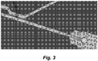
- FIG. 3 One illustrative, but non-limiting schematic of an integrated droplet generation and merging modules for high speed production of multiplexed droplets is shown in Figure 3 .
- the devices described herein utilize a thin-layer soft lithography process to produce certain structures (e.g., valve membranes).
- a thin-layer soft lithography process to produce certain structures (e.g., valve membranes).
- the fabrication of thin layers of, e.g., PDMS is enabled by a novel Pt-PDMS thin film process described in copending provisional application no: 61/616,385, filed on March 27, 2012 , and in copending provisional application entitled "CONTINUOUS WHOLE-CHIP 3-DIMENSIONAL DEP CELL SORTER AND RELATED FABRICATION METHOD", filed on March 15, 2013.
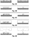
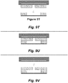
- Figures 9A through 9ZB In particular one implementation of this ptPDMS fabrication process is depicted via simplified cross-sectional views in Figures 9A through 9ZB .
- the structure that is being constructed in Figures 9A through 9ZB is a portion of a three-dimensional DEP cell sorter, e.g., the features within the DEP separation region of such a cell sorter, however the same fabrication method is readily applied to fabrication of the devices described herein (e.g., on-demand lateral membrane valve).
- Figures 9A through 9ZB are not drawn to scale.
- the Figures depict two different manufacturing streams-the steps in the streams may be largely the same, but the molds used may have different feature sizes.
- each Figure depicts the formation of a PDMS layer that may be used to provide a first passage or a second passage, e.g., of a cell sorter, droplet injector, and the like
- the cross-sections on the right side of each Figure may depict the formation of a PDMS layer that may be used to provide a sorting passage of the cell sorter, injection passage of a droplet former, and the like.
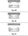
- Figures 9Q through 9ZB depict the assembly of the layers into an assembled cell sorter (e.g., as described in copending provisional application no: 61/616,385, filed on March 27, 2012 ,).
- a hard substrate may be prepared for etching by depositing or providing a photo-patternable or photo-resistive material on the substrate.
- a photo-patternable or photo-resistive material may be, for example, negative photoresist SU8 or positive photoresist AZ4620, and the substrate may, for example, be silicon or glass, although other photoresists or photo-patternable materials may be used as well, as well as other substrate materials.
- an etching operation can remove material from the hard substrate to form a master mold.
- the raised features on the master mold can be formed by deposition instead of etching. In certain embodiments both etching and deposition can be used to form features on the master mold.
- the master mold is coated with a conformal silane surface treatment to facilitate later removal of cured PDMS from the molds.
- uncured PDMS (or other soft lithographic material) may be poured onto the master mold and cured to form a complementary PDMS mold.
- the PDMS mold may then be separated from the master mold.
- the PDMS mold may be coated with a conformal silane surface treatment.
- the PDMS mold may be temporarily set aside and another hard substrate, e.g., silicon or glass, may be prepared by pouring uncured PDMS onto the substrate.
- the PDMS mold may be retrieved, and in Figure 9I , the PDMS mold may be pressed into the uncured PDMS on the substrate and the uncured PDMS may then be cured.
- the PDMS mold may be removed from the cured PDMS on the substrate.
- the resulting PDMS structure on the substrate may be an exact, or near-exact, duplicate of the master mold and may be referred to herein as a PDMS master mold.
- a hard master mold or a "soft” (e.g., PDMS) master mold can be used.
- a hard master mold will reduce thin film distortion during the molding process.
- people use SU-8 mold (a hard master mold) to make PDMS structures.
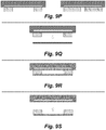
- the PDMS master mold may be coated with a CYTOPTM surface treatment to assist in later removal of cast PDMS parts.
- Uncured PDMS may be applied to the PDMS master mold (see, e.g., Figure 9L ).
- the steps discussed above with respect to Figures 9A through 9L are similar, in large part, to existing PDMS layer fabrication processes.
- Figure 9M depicts a step that deviates from existing fabrication techniques.
- a PDMS stamping e.g., a large, flat, featureless base
- the PDMS stamping has been modified to include a plate of material within the PDMS that has a much higher modulus than the PDMS (e.g., is stiffer than the PDMS).
- the plate is located such that a very thin layer of PDMS exists between the plate and the uncured PDMS and the PDMS master mold. This thin layer may be, for example, on the order of 500 microns or less in thickness.
- the plate may be plastic, glass, or other material with a substantially higher modulus than that of PDMS. In practice, plastic plates have proven to be more robust than glass plates. Without being bound to a particular theory, the plate may act as an intermediate load spreader within the PDMS stamping to distribute a compression load across the PDMS master mold and the uncured PDMS.
- the thin layer of PDMS can allow for very small localized deflections that facilitate full contact between the PDMS mold and the stamping while avoiding the creation of large edge ridges that may appear when a traditional stamping is used.
- the embedded-plate stamping shown may be provided by spin-coating the plate with PDMS.
- PDMS exhibits inconsistent curing behavior when applied in too thin a layer. Indeed, in many thin film situations, it was observed that the PDMS does not cure at all and remains in a liquid state. Thus, it was discovered that the PDMS will not reliably set at thicknesses such as those discussed above, resulting in an unreliable manufacturing technique. It was a surprising discovery that if the PDMS that forms the thin layer on the stamping is doped with a catalyst (e.g., a platinum catalyst), however, the PDMS will set reliably regardless of thickness.
- a catalyst e.g., a platinum catalyst
- the fabrication techniques contemplated herein may include preparing a stamping (this step is not shown) by coating a substantially rigid plate with a thin layer of platinum-doped PDMS. It was discovered that providing platinum ions to the uncured PDMS insures consistent, relatively uniform, curing. It was also surprisingly discovered that with addition of enough platinum ions, the PDMS cured in a short time even at room temperature.
- the catalyst is platinum-divinyltetramethyldisiloxane (C 8 H 18 OPtSi 2 ).
- the stamping may also have a thicker layer of PDMS on the opposite side of the plate to allow for easy handling or integration with existing equipment, although such a thicker layer is not strictly necessary.
- the thin layer of PDMS (or the entire PDMS stamping) may be treated with a silane surface treatment, e.g. , trichloro (1H,1H,2H,2H-perfluorooctyl) silane (also referred to as "PFOCTS").
- the stamping has been compressed against the uncured PDMS and the PDMS master mold and then cured.
- the cured PDMS layer is removed from the PDMS master mold by pulling the stamping away from the PDMS master mold. Due to the higher bond strength in silane-treated surfaces as compared with CYTOP-treated surfaces, the PDMS layer will stay bonded to the stamping, allowing for easy transfer to other structures.
- Figure 9P depicts the removed PDMS layer bonded to the stamping; the PDMS layer may be treated with an oxygen plasma to facilitate later bonding with a glass or PDMS structure.
- one of the PDMS layers is positioned over a prepared glass substrate; the glass substrate may, for example, be prepared by coating it with an electrically-conductive coating such as ITO so that it may act as an electrode layer of a DEP cell sorter.
- the PDMS layer may be directly bonded to the glass substrate as a result of the oxygen plasma treatment of the PDMS layer.
- the stamping may be removed--due to the higher bond strength of the direct bonding via oxygen plasma treatment as compared with the bond across the silane-treated surfaces, the PDMS layer may separate from the stamping and remain cleanly attached to the glass substrate.
- the PDMS layer placed on the substrate in this case corresponds to a sublayer of an electrically-insulating layer in a DEP cell sorter having a first or second passage in it.
- another PDMS layer (in one embodiment time corresponding with a sublayer of an electrically-insulating layer in a DEP cell sorter having a sorting passage in it), may be positioned over the previously-placed PDMS layer using the stamping to which it is attached.
- This second PDMS layer may also be treated with an oxygen plasma to facilitate direct bonding to the previously-placed PDMS layer.
- the second PDMS layer may be directly bonded to the first PDMS layer by compressing it into the first PDMS layer with the stamping.
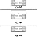
- the stamping may be removed in much the same manner as in Figure 9S .
- a third PDMS layer in this case similar to the first PDMS layer, may be positioned over the first and second PDMS layers.
- the third PDMS layer as with the other PDMS layers, may be treated with an oxygen plasma.
- the third PDMS layer may be directly bonded to the second PDMS layer to form a three-layer stack of PDMS layers that are fused into one, essentially contiguous, structure.
- the stamping may be removed, leaving the 3-layer PDMS structure behind.
- the exposed top of the PDMS structure may be prepared for bonding to another hard substrate, e.g., glass.
- the hard substrate may be positioned over the assembled PDMS stack, and in Figure 9ZB , the hard substrate may be bonded to the stack.
- the resulting structure provides very clean interlayer via features, and is particularly well-suited for microfluidic devices.
- the above technique may be modified as needed to omit certain steps, add other steps, and otherwise tailor the technique for particular design requirements. For example, it may be possible to form features with stepped cross-sections in the molds, thus reducing the number of individual layers that must be made and bonded together. While the depicted technique was shown for a 3-layer stack of PDMS layers, more or less PDMS layers may be manufacturing in this manner and assembled into a PDMS layer stack.
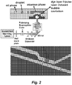
- FIG. 2 schematically illustrates an embodiment of a pulse laser driven membrane valve droplet generator.
- a thin membrane e.g ., a PDMS membrane
- PDMS membrane e.g., a PDMS membrane
- Each laser pulse can trigger a caviation bubble to deform the membrane to squeeze out a droplet through the nozzle into the oil phase.
- a static pressure source can be used to maintain the stable (e.g. , water-oil) interface. This approach dramatically reduces the consumption of expensive and precious reagents.
- the interface can automatically recover to its original location in a very short time period since the membrane is only partially and locally deformed.
- the droplet generation rate can go up to hundreds of Hz.
- the volume of droplets produced on certain embodimnts of this platform is around 80 pL as shown in Figure 4 .
- microchannels incorporate microchannels (microfluidic channels).
- microfluidic channel or “microchannel” are used interchangeably and refer to a channel having at least one characteristic dimension (e.g ., width or diameter) less than 1,000 ⁇ m, more preferably less than about 900 ⁇ m, or less than about 800 ⁇ m, or less than about 700 ⁇ m, or less than about 600 ⁇ m, or less than about 500 ⁇ m, or less than about 400 ⁇ m, or less than about 300 ⁇ m, or less than about 250 ⁇ m, or less than about 200 ⁇ m, or less than about 150 ⁇ m, or less than about 100 ⁇ m, or less than about 75 ⁇ m, or less than about 50 ⁇ m, or less than about 40 ⁇ m, or less than about 30 ⁇ m, or less than about 20 ⁇ m.
- characteristic dimension e.g ., width or diameter
- the methods and devices described herein may utilize immiscible fluids.
- immiscible when used with respect to two fluids indicates that the fluids when mixed in some proportion, do not form a solution.
- Classic immiscible materials are water and oil.
- Immiscible fluids, as used herein also include fluids that substantially do not form a solution when combined in some proportion. Commonly the materials are substantially immiscible when they do not form a solution if combined in equal proportions.
- immiscible fluids include fluids that are not significantly soluble in one another, fluids that do not mix for a period of time due to physical properties such as density or viscosity, and fluids that do not mix for periods of time due to laminar flow.
- such fluids are not restricted to liquids but may include liquids and gases.
- an aqueous solvent such as water
- any number of organic compounds such as carbon tetrachloride, chloroform, cyclohexane, 1,2-dichloroethane, dichloromethane, diethyl ether, dimethyl formamide, ethyl acetate, heptane, hexane, methyl-tert-butyl ether pentane, toluene, 2,2,4-trimethylpentane, and the like are contemplated.
- Various mutually insoluble solvent systems are well known to those skilled in the art (see e.g. Table 1).
- droplets of aqueous buffer containing physiologically normal amounts of solute may be produced in a dense aqueous buffer containing high concentrations of sucrose.
- droplets of an aqueous buffer containing physiologically normal amounts of solute may be produced in a second aqueous buffer containing physiologically normal amounts of solute where the two buffers are segregated by laminar flow.
- droplets of a fluid may be produced in a gas such as nitrogen or air.
- Table 1 illustrates various solvents that are either miscible or immiscible in each other.
- the solvent on left column does not mix with solvents on right column unless otherwise stated.
- Solvents Immiscibility Acetone can be mixed with any of the solvents listed in the column at left
- Acetonitrile cyclohexane, heptane, hexane, pentane, 2,2,4-trimethylpentane carbon tetrachloride can be mixed with any of the solvents listed in the column at left except water chloroform can be mixed with any of the solvents listed in the column at left except water cyclohexane acetonitrile, dimethyl formamide, dimethyl sulfoxide, methanol, water 1,2-dichloroethane can be mixed with any of the solvents listed in the column at left except water dichloromethane can be mixed with any of the solvents listed in the column at left except water diethyl ether dimethyl sulfoxide, water di
- first fluid and second fluid need not be immiscible in each other.
- injected droplets can be kept separate from each other simply by adjusting flow rates in the microchannels and rate of bubble formation to form separated bubbles.
- the droplets generated by the devices and methods described herein can contain or encapsulate a wide variety of materials.
- the droplets may contain test samples, cells, organelles, proteins, nucleic acids, enzymes, PCR or other testing reagents, biochemicals, dyes, or particulates (for example polymeric microspheres, metallic microparticles, or pigments).
- a droplet may encapsulate one or more previously generated droplets.
- the invention need not be limited to aqueous droplet systems.
- such droplet generating methods and devices may be used in nanoparticle coating, where materials in organic solvents can be used to deposit layers on or encapsulate nanoparticles.
- an opening in a fluid channel can be configured as a nozzle.
- the depth, inner diameter, and outer diameter of such a nozzle can be optimized to control droplet size, droplet uniformity, mixing at the fluid interface, or a combination of these.
- the droplet generation and/or droplet merger components described herein may be provided on a substrate that differs from the material that comprises the fluid channels.
- the fluid channels may be fabricated using an elastomeric material that is disposed upon a rigid surface.
- Suitable fluid channel materials include but are not limited to flexible polymers such as PDMS, plastics, and similar materials. Fluid channels may also be comprised of nonflexible materials such as rigid plastics, glass, silicon, quartz, metals, and similar material.
- Suitable substrates include but are not limited to transparent substrates such as polymers, plastic, glass, quartz, or other dielectric materials. Other suitable substrate materials include but are not limited to nontransparent materials such as opaque or translucent plastics, silicon, metal, ceramic, and similar materials.
- the droplet generating devices and the connecting fluid channels are comprised of PDMS (or other polymers), and fabricated using soft lithography.
- PDMS is an attractive material for a variety of reasons, including but not limited to low cost, optical transparency, ease of molding, and elastomeric character.
- PDMS also has desirable chemical characteristics, including compatibility with both conventional siloxane chemistries and the requirements of cell culture (e.g. low toxicity, gas permeability).
- a master mold is prepared to form the fluid channel system.
- This master mold may be produced by a micromachining process, a photolithographic process, or by any number of methods known to those with skill in the art. Such methods include, but are not limited to, wet etching, electron-beam vacuum deposition, photolithography, plasma enhanced chemical vapor deposition, molecular beam epitaxy, reactive ion etching, and/or chemically assisted ion beam milling ( Choudhury (1997) The Handbook of Microlithography, Micromachining, and Microfabrication, Soc. Photo-Optical Instru. Engineer.; Bard & Faulkner, Fundamentals of Microfabrication ).
- the master mold is exposed to a pro-polymer, which is then cured to form a patterned replica in PDMS.
- the replica is removed from the master mold, trimmed, and fluid inlets are added where required.
- the polymer replica may be optionally be treated with a plasma (e.g . an O 2 plasma) and bonded to a suitable substrate, such as glass.
- a plasma e.g . an O 2 plasma
- O 2 plasma e.g. an O 2 plasma
- Treatment of PDMS with O 2 plasma generates a surface that seals tightly and irreversibly when brought into conformal contact with a suitable substrate, and has the advantage of generating fluid channel walls that are negatively charged when used in conjunction with aqueous solutions.
- These fixed charges support electrokinetic pumping that may be used to move fluid through the device.
- single layer devices are contemplated.
- multilayer devices are contemplated.
- a multilayer network of fluid channels may be designed using a commercial CAD program. This design may be converted into a series of transparencies that is subsequently used as a photolithographic mask to create a master mold. PDMS cast against this master mold yields a polymeric replica containing a multilayer network of fluid channels. This PDMS cast can be treated with a plasma and adhered to a substrate as described above.
- the fluid channels are microchannels.
- Such microchannels have characteristic dimensions ranging from about 100 nanometers to 1 micron up to about 500 microns. In various embodiments the characteristic dimension ranges from about 1, 5, 10, 15, 20, 25, 35, 50 or 100 microns up to about 150, 200, 250, 300, or 400 microns. In some embodiments the characteristic dimension ranges from about 20, 40, or about 50 microns up to about 100, 125, 150, 175, or 200 microns.
- the wall thickness between adjacent fluid channels ranges from about 0.1 micron to about 50 microns, or about 1 micron to about 50 microns, more typically from about 5 microns to about 40 microns. In certain embodiments the wall thickness between adjacent fluid channels ranges from about 5 microns to about 10, 15, 20, or 25 microns.
- the depth of a fluid channel ranges from 5, 10, 15, 20 microns to about 1mm, 800 microns, 600 microns, 500 microns, 400 microns, 300 microns, 200 microns, 150 microns, 100 microns, 80 microns, 70 microns, 60 microns, 50 microns, 40 microns, or about 30 microns. In certain embodiments the depth of a fluid channel ranges from about 10 microns to about 60 microns, more preferably from about 20 microns to about 40 or 50 microns. In some embodiments the fluid channels can be open; in other embodiments the fluid channels may be covered.
- a nozzle is present.
- the nozzle diameter can range from about 0.1 micron, or about 1 micron up to about 300 microns, 200 microns, or about 100 microns.
- the nozzle diameter can range from about 5, 10, 15, or 20 microns up to about 25, 30, 35, 40, 45, 50, 55, 60, 65, 70, 75, or about 80 microns.
- the nozzle diameter ranges from about 1, 5, 10, 15, or 20 microns to about 25, 35, or 40 microns.
- the methods and devices described herein can generate droplets at a rate ranging from zero droplets/sec, about 2 droplets/sec, about 5 droplets/sec, about 10 droplets/sec, about 20 droplets/sec, about 50 droplets/sec, about 100 droplets/sec, about 500 droplets/sec, or about 1000 droplets/sec, up to about 1,500 droplets/sec, about 2,000 droplets/sec, about 4,000 droplets/sec, about 6,000 droplets/sec, about 8,000 droplets/sec, about 10,000 droplets/sec, about 20,000 droplets/sec, about 50,000 droplets/sec, and about 100,000 droplets/sec.
- the devices and methods described herein can generate droplets having a substantially continuous volume.
- Droplet volume can be controlled to provide volumes ranging from about 0.1fL, about 1fL, about 10 fL, and about 100 fL to about 1 microliter, about 500 nL, about 100nL, about 1 nL, about 500 pL or about 200 pL.
- volume control of the droplet ranges from about 1 pL to about 150 pL, about 200 pL, about 250 pL, or about 300 pL.
- microchannel droplet formation/merger injection devices described herein can provide a system integrated with other processing modules on a microfluidic "chip” or in flow through fabrication systems for microparticle coating, microparticle drug carrier formulation, and the like. These uses, however, are merely illustrative and not limiting.
- Microfluidic devices can manipulate volumes as small as several nanoliters. Because the microfluidic reaction volume is close to the size of single mammalian cells, material loss is minimized in single-cell mRNA analysis with these devices. The ability to process live cells inside microfluidic devices provides a great advantage for the study of single-cell transcriptomes because mRNA is rapidly degraded with cell death.
- a highly integrated microfluidic device, having 26 parallel 10 nL reactors for the study of gene expression in single human embryonic stem cells (hESC) has been reported ( Zhong et al. (2008) Lab on a Chip, 8: 68-74 ; Zhong et al. (2008) Curr. Med. Chem., 15: 2897-2900 ).
- microfluidic devices all systems for obtaining single-cell cDNA including cell capture, mRNA capture/purification, cDNA synthesis/purification, are performed inside the device.
- the present devices and methods offer effective means of encapsulating and and/or separating individual cells for, e.g., further processing,
- any of a number of approaches can be used to convey the fluids, or mixtures of droplets, particles, cells, etc. along the channels of the devices described herein.
- Such approaches include, but are not limited to gravity flow, syringe pumps, peristaltic pumps, electrokinetic pumps, bubble-driven pumps, and air pressure driven pumps.
Claims (16)
- Vorrichtung zur Manipulation mikrofluidischer Tröpfchen, wobei die Vorrichtung ein Substrat umfasst, das Folgendes trägt oder umfasst:
eine oder mehrere Tröpfchenverschmelzungskomponenten, wobei die Tröpfchenverschmelzungskomponente(n), Folgendes umfasst/umfassen:(i) einen mittigen Kanal, der mehrere Elemente umfasst, die dazu angeordnet und beabstandet sind, mehrere laterale Durchgänge auszubilden, die ein Trägerfluid aus einem Fluidstrom ablassen, das Tröpfchen eines im Trägerfluid enthaltenen ersten Fluids umfasst; und(ii) ein verformbares laterales Membranventil, das dazu angeordnet ist, die Breite des mittigen Kanals zu steuern, wobei das laterale Membranventil nach den mehreren Elementen angeordnet ist. - Vorrichtung nach Anspruch 1, wobei:(a) sich die Breite des mittigen Kanals als Abstandsfunktion stromabwärts durch die mehreren lateralen Durchgänge verringert; und/oder(b) die Breite der lateralen Durchgänge kleiner als die Breite des mittigen Kanals an derselben Stelle ist.
- Vorrichtung nach einem der Ansprüche 1-2, wobei die mehreren Elemente eine Mikrozylinderanordnung umfassen, wobei die Mikrozylinderanordnung Zylinderpaare umfasst, die laterale Kanäle ausbilden, die stromabwärts abgeschrägt sind, und wobei Zylinder, die die Mikrozylinderanordnung umfassen, dazu ausgelegt sind, einen Zwischenzylinderabstand vorzusehen, der 0,1 µm bis 100 µm oder 0,1 µm bis 10 µm beträgt.
- Vorrichtung nach einem der Ansprüche 1-3, wobei die Vorrichtung eine Steuerung umfasst, die das laterale Membranventil betätigt und das Ausmaß und den Zeitpunkt der Verengung des Membranventils steuert.
- Vorrichtung nach Anspruch 4, wobei die Steuerung des Ausmaßes und des Zeitpunkts der Verengung des lateralen Membranventils den Zeitpunkt der Tröpfchenverschmelzung und/oder die Anzahl der verschmolzenen Tröpfchen steuert.
- Vorrichtung nach einem der Ansprüche 1-5, wobei das Substrat ferner Folgendes trägt oder umfasst:
einen oder mehrere Tröpfchengeneratoren, wobei der/die Tröpfchengenerator(en) Folgendes umfasst/umfassen:(i) einen ersten Mikrofluidkanal, der ein erstes Fluid enthält und an einen zweiten Mikrofluidkanal, der ein zweiten Fluid enthält, angrenzt, wobei der erste Mikrofluidkanal mit dem zweiten Mikrofluidkanal in Fluidverbindung steht und das erste Fluid im Wesentlichen mit dem zweiten Fluid unmischbar ist; und(ii) einen Kavitationskanal oder eine Kavitationskammer, in dem/der der Inhalt des Kavitationskanals oder der Kavitationskammer vom Inhalt des ersten Mikrofluidkanals durch eine verformbare Kanalwand oder Kammerwand getrennt ist, wobei der Kavitationskanal oder die Kavitationskammer dazu ausgelegt ist, zuzulassen, dass sich die verformbare Kanalwand oder Kammerwand verformt, wenn im Kavitationskanal oder in der Kavitationskammer eine Blase ausgebildet wird, und wobei der Kavitationskanal oder die Kavitationskammer über oder unter dem ersten Mikrofluidkanal angeordnet ist. - Vorrichtung nach Anspruch 6, wobei der erste Mikrofluidkanal über einen Stutzen oder einen Kanal mit dem zweiten Mikrofluidkanal in Fluidverbindung steht.
- Vorrichtung nach einem der Ansprüche 6 und 7, wobei in dem/den Tröpfchengenerator(en) ein erster Abschnitt des ersten Mikrofluidkanals in einem ersten Abstand zum zweiten Mikrofluidkanal angeordnet ist und ein zweiter Abschnitt des ersten Mikrofluidkanals in einem zweiten Abstand zum zweiten Mikrofluidkanal angeordnet ist und der zweite Abstand kleiner als der erste Abstand ist und optional wobei der erste Mikrofluidkanal einen dritten Abschnitt umfasst, der derart angeordnet ist, dass sich der zweite Abschnitt zwischen dem ersten Abschnitt und dem dritten Abschnitt befindet und sich der dritte Abschnitt des Mikrofluidkanals in einem dritten Abstand zum zweiten Mikrofluidkanal befindet und der dritte Abstand größer als der zweite Abstand ist.
- Vorrichtung nach einem der Ansprüche 6-8, wobei:(a) die Maximalbreite des ersten Mikrofluidkanals und/oder des zweiten Mikrofluidkanals 0,1 µm bis 500 µm, vorzugsweise 50 µm bis 100 µm, oder 100 µm beträgt; und/oder(b) die Maximalbreite des ersten Mikrofluidkanals und/oder des zweiten Mikrofluidkanals 0,1 µm bis 500 µm, vorzugsweise 40 µm bis 80 µm, und/oder 50 µm beträgt.
- Vorrichtung nach einem der Ansprüche 6-9, wobei:(a) der Tröpfchengenerator dazu ausgelegt ist, Tröpfchen zu erzeugen, die ein Volumen von 1 Attoliter bis 1 µl, vorzugsweise ein Volumen von 1 pl bis 150 pl aufweisen; und/oder(b) der Kavitationskanal oder die Kavitationskammer ein Kavitationskanal ist, der zulässt, dass der Inhalt des Kanals strömt, und dadurch zur Zerstreuung einer darin ausgebildeten Blase beiträgt; und/oder(c) der erste Mikrofluidkanal dazu ausgelegt ist, das erste Fluid unter einem im Wesentlichen statischen Druck vorzusehen, um eine stabile Schnittstelle zwischen dem ersten Fluid und dem zweiten Fluid zu erzeugen.
- Vorrichtung nach einem der Ansprüche 6-10, wobei:(a) das erste Fluid ein wässriges Fluid umfasst; und/oder(b) das zweite Fluid ein Öl oder ein organisches Lösungsmittel umfasst.
- Vorrichtung nach einem der Ansprüche 6-11, wobei der Generator in einem System vorkommt, das eine Energiequelle umfasst, die dazu ausgelegt ist, eine Blase im Kavitationskanal oder in der Kavitationskammer auszubilden, und wobei die Energiequelle ein Impulslaser ist.
- Verfahren zum Kombinieren von Tröpfchen in einem Mikrofluidsystem, wobei das Verfahren das Vorsehen mehrerer Tröpfchen umfasst, die durch einen Mikrofluidkanal in den/die mittigen Kanal/Kanäle einer oder mehrerer Tröpfchenverschmelzungskomponenten nach Anspruch 1-5 strömen, wodurch das Verschmelzen mehrerer Tröpfchen bewirkt wird.
- Verfahren nach Anspruch 13, wobei das Verfahren das Variieren der Verengung umfasst, die durch das laterale Membranventil erzeugt wird, um den Zeitpunkt der Tröpfchenverschmelzung und/oder die Anzahl verschmolzener Tröpfchen zu steuern.
- Verfahren nach Anspruch 14, wobei das Variieren der Verengung das Bedienen einer Steuerung umfasst, die das/die laterale/n Membranventil/e pneumatisch betätigt.
- Verfahren nach Anspruch 13, wobei das Verfahren Folgendes umfasst:Vorsehen einer Vorrichtung nach Anspruch 6;Aufwenden einer Energiequelle auf einen Kavitationskanal oder eine Kavitationskammer eines oder mehrerer des einen oder der mehreren Tröpfchengeneratoren, wobei die Energiequelle Blasen in dem Kavitationskanal oder in der Kavitationskammer ausbildet, um die verformbare Kanalwand oder Kammerwand zu verformen und ein Tröpfchen des ersten Fluids in das zweite Fluid im zweiten Mikrofluidkanal einzuspritzen;Aufnehmen mehrerer Tröpfchen, die durch den einen oder die mehreren Tröpfchengeneratoren erzeugt wurden, in mindestens einer der einen oder mehreren Tröpfchenverschmelzungskomponenten, wobei die Tröpfchen verschmelzen, um ein kombiniertes Tröpfchenfluid auszubilden.
Applications Claiming Priority (2)
| Application Number | Priority Date | Filing Date | Title |
|---|---|---|---|
| US201361798516P | 2013-03-15 | 2013-03-15 | |
| PCT/US2014/026185 WO2014151658A1 (en) | 2013-03-15 | 2014-03-13 | High-speed on demand microfluidic droplet generation and manipulation |
Publications (3)
| Publication Number | Publication Date |
|---|---|
| EP2972405A1 EP2972405A1 (de) | 2016-01-20 |
| EP2972405A4 EP2972405A4 (de) | 2016-10-19 |
| EP2972405B1 true EP2972405B1 (de) | 2020-12-23 |
Family
ID=51581005
Family Applications (1)
| Application Number | Title | Priority Date | Filing Date |
|---|---|---|---|
| EP14768515.0A Active EP2972405B1 (de) | 2013-03-15 | 2014-03-13 | Schnelle mikrofluidische tröpfchenerzeugung und manipulation auf anfrage |
Country Status (8)
| Country | Link |
|---|---|
| US (2) | US10071359B2 (de) |
| EP (1) | EP2972405B1 (de) |
| JP (1) | JP6461905B2 (de) |
| KR (1) | KR102168053B1 (de) |
| CN (1) | CN105452873B (de) |
| AU (1) | AU2014233699B2 (de) |
| CA (1) | CA2909687A1 (de) |
| WO (1) | WO2014151658A1 (de) |
Families Citing this family (51)
| Publication number | Priority date | Publication date | Assignee | Title |
|---|---|---|---|---|
| US9364831B2 (en) | 2009-08-08 | 2016-06-14 | The Regents Of The University Of California | Pulsed laser triggered high speed microfluidic switch and applications in fluorescent activated cell sorting |
| US9176504B2 (en) | 2011-02-11 | 2015-11-03 | The Regents Of The University Of California | High-speed on demand droplet generation and single cell encapsulation driven by induced cavitation |
| CN104736725A (zh) | 2012-08-13 | 2015-06-24 | 加利福尼亚大学董事会 | 用于检测生物组分的方法和系统 |
| EP2972405B1 (de) | 2013-03-15 | 2020-12-23 | The Regents of The University of California | Schnelle mikrofluidische tröpfchenerzeugung und manipulation auf anfrage |
| EP3160654A4 (de) | 2014-06-27 | 2017-11-15 | The Regents of The University of California | Pcr-aktivierte sortierung (pas) |
| CN105441308B (zh) * | 2014-08-27 | 2018-03-20 | 中国科学院苏州纳米技术与纳米仿生研究所 | 循环式单细胞捕获芯片 |
| CN105441309B (zh) * | 2014-08-27 | 2018-04-27 | 中国科学院苏州纳米技术与纳米仿生研究所 | 循环式单细胞捕获转移芯片 |
| WO2016064755A2 (en) * | 2014-10-20 | 2016-04-28 | The Regents Of The University Of Califronia | Rapid modulation of droplet composition with membrane microvalves |
| US10434507B2 (en) | 2014-10-22 | 2019-10-08 | The Regents Of The University Of California | High definition microdroplet printer |
| EP3253479B1 (de) | 2015-02-04 | 2022-09-21 | The Regents of The University of California | Sequenzierung von nukleinsäuren durch barcodierung bei diskreten einheiten |
| WO2016133783A1 (en) * | 2015-02-17 | 2016-08-25 | Zalous, Inc. | Microdroplet digital pcr system |
| CN106290492A (zh) * | 2015-05-11 | 2017-01-04 | 宁波大学 | 驱动用构件易拆解并可循环再用的霍乱诊断用装置 |
| WO2016187561A1 (en) | 2015-05-20 | 2016-11-24 | University Of Maryland, College Park | Generation and trapping of aqueous droplets in a microfluidic chip with an air continuous phase |
| CN106290930A (zh) * | 2015-05-26 | 2017-01-04 | 宁波大学 | 含疏水基片的双驱动耦合的亚型猪流感多通道检测装置 |
| CN106290857A (zh) * | 2015-05-26 | 2017-01-04 | 宁波大学 | 多通道且双驱动耦合运作的霍乱诊断用微流控芯片装置 |
| CN106290932A (zh) * | 2015-05-26 | 2017-01-04 | 宁波大学 | 包含疏水基片的双驱动耦合的艾滋病诊断用多通道装置 |
| CN106290856A (zh) * | 2015-05-26 | 2017-01-04 | 宁波大学 | 四通道并且双驱动耦合运作的艾滋病诊断用微流控装置 |
| CN106290933A (zh) * | 2015-05-26 | 2017-01-04 | 宁波大学 | 双机制驱动耦合运作的霍乱诊断用微流控芯片装置 |
| CN106290931A (zh) * | 2015-05-26 | 2017-01-04 | 宁波大学 | 以廉价疏水材质作基片的亚型猪流感检测用多通道装置 |
| CN105136763B (zh) * | 2015-09-10 | 2017-10-13 | 大连海事大学 | 基于气液界面单细胞捕获及叶绿素荧光表征的单微藻细胞活性动态监测新方法与装置 |
| CN106556708A (zh) * | 2015-09-24 | 2017-04-05 | 宁波大学 | 两种驱动方式耦合运作的含疏水基片的微流控芯片装置 |
| EP3269444A1 (de) * | 2016-07-14 | 2018-01-17 | Base4 Innovation Ltd | Verfahren zur identifizierung von tröpfchen in einem stapel und zugehöriger sequenzierer |
| WO2018031691A1 (en) | 2016-08-10 | 2018-02-15 | The Regents Of The University Of California | Combined multiple-displacement amplification and pcr in an emulsion microdroplet |
| WO2018099420A1 (zh) * | 2016-11-30 | 2018-06-07 | 领航基因科技(杭州)有限公司 | 微滴式数字pcr芯片 |
| AU2017382905A1 (en) | 2016-12-21 | 2019-07-04 | The Regents Of The University Of California | Single cell genomic sequencing using hydrogel based droplets |
| WO2019006190A1 (en) | 2017-06-28 | 2019-01-03 | Bio-Rad Laboratories, Inc. | SYSTEM AND METHOD FOR DROPLELET DETECTION |
| CN107694475B (zh) * | 2017-09-25 | 2021-02-19 | 南京航空航天大学 | 一种微纳物质的环状聚集物成形装置 |
| US10501739B2 (en) | 2017-10-18 | 2019-12-10 | Mission Bio, Inc. | Method, systems and apparatus for single cell analysis |
| CN107904155B (zh) * | 2017-10-19 | 2021-06-22 | 广州市第一人民医院 | 一种用于液体分散的微流控芯片及其应用、使用方法 |
| US11045805B2 (en) | 2017-11-01 | 2021-06-29 | Bio-Rad Laboratories, Inc. | Microfluidic system and method for arranging objects |
| JP7030361B2 (ja) * | 2017-11-06 | 2022-03-07 | 北京新▲い▼生物科技有限公司 | 微小液滴生成装置 |
| WO2020002197A1 (en) | 2018-06-27 | 2020-01-02 | Institut Curie | Method of inducing or preventing the merging of droplets |
| EP3586964A1 (de) | 2018-06-27 | 2020-01-01 | Inorevia | Verfahren zur manipulation von tröpfchen in einem kanal |
| US11167287B2 (en) | 2018-07-30 | 2021-11-09 | Hrl Laboratories, Llc | Dissolving droplet microfluidic particle assembly devices and methods, and particle assemblies obtained therefrom |
| US11173464B2 (en) | 2018-07-30 | 2021-11-16 | Hrl Laboratories, Llc | Methods for dissolving droplet particle assembly with co-solvent, and particle assemblies obtained therefrom |
| US11845061B1 (en) | 2018-07-30 | 2023-12-19 | Hrl Laboratories, Llc | Complex structures obtained from dissolving-droplet nanoparticle assembly |
| EP3613498A1 (de) * | 2018-08-24 | 2020-02-26 | Université de Liège | Mikrofluidisches modul zur co-einkapselung in tröpfchenform |
| CN109456890A (zh) * | 2018-11-23 | 2019-03-12 | 大连理工大学 | 一种分层带状共培养4种肝细胞的微流控芯片及其应用 |
| EP3973074A4 (de) | 2019-05-22 | 2023-09-06 | Mission Bio, Inc. | Verfahren und vorrichtung zur simultanen gezielten sequenzierung von dna, rna und protein |
| WO2021003255A1 (en) | 2019-07-01 | 2021-01-07 | Mission Bio | Method and apparatus to normalize quantitative readouts in single-cell experiments |
| US20220250077A1 (en) * | 2019-07-24 | 2022-08-11 | Hewlett-Packard Development Company, L.P. | Digital microfluidics device with droplet processing components |
| US20220297350A1 (en) * | 2019-08-30 | 2022-09-22 | Drexel University | 3d capillary self-assembly of long aspect ratio particles |
| US11376812B2 (en) | 2020-02-11 | 2022-07-05 | Helicoid Industries Inc. | Shock and impact resistant structures |
| US20230142172A1 (en) * | 2020-03-13 | 2023-05-11 | Japan Science And Technology Agency | Microdroplet/bubble generation device |
| CN112871227B (zh) * | 2021-01-07 | 2022-10-11 | 中国科学院青岛生物能源与过程研究所 | 基于光热效应进行微量液滴操控的微流控芯片及方法 |
| US11346499B1 (en) | 2021-06-01 | 2022-05-31 | Helicoid Industries Inc. | Containers and methods for protecting pressure vessels |
| US11852297B2 (en) | 2021-06-01 | 2023-12-26 | Helicoid Industries Inc. | Containers and methods for protecting pressure vessels |
| IT202100014972A1 (it) | 2021-06-09 | 2021-09-09 | Iodo S R L | Sistema microfluidico a liquidi espansi per la produzione di drug carrier |
| CN113652333B (zh) * | 2021-08-03 | 2023-03-21 | 中国科学院上海微系统与信息技术研究所 | 一种优化流体分布的微柱式多相位移通道 |
| WO2024006078A1 (en) | 2022-06-27 | 2024-01-04 | Helicoid Industries Inc. | High impact-resistant, reinforced fiber for leading edge protection of aerodynamic structures |
| US11802870B1 (en) | 2022-12-13 | 2023-10-31 | Panazee | Kinetic immunoassay systems and methods |
Family Cites Families (49)
| Publication number | Priority date | Publication date | Assignee | Title |
|---|---|---|---|---|
| JP2832117B2 (ja) | 1991-11-29 | 1998-12-02 | キヤノン株式会社 | サンプル測定デバイス及びサンプル測定システム |
| US6143496A (en) | 1997-04-17 | 2000-11-07 | Cytonix Corporation | Method of sampling, amplifying and quantifying segment of nucleic acid, polymerase chain reaction assembly having nanoliter-sized sample chambers, and method of filling assembly |
| US7214298B2 (en) | 1997-09-23 | 2007-05-08 | California Institute Of Technology | Microfabricated cell sorter |
| US6899137B2 (en) | 1999-06-28 | 2005-05-31 | California Institute Of Technology | Microfabricated elastomeric valve and pump systems |
| US6524456B1 (en) | 1999-08-12 | 2003-02-25 | Ut-Battelle, Llc | Microfluidic devices for the controlled manipulation of small volumes |
| AU1592501A (en) | 1999-11-10 | 2001-06-06 | Massachusetts Institute Of Technology | Cell analysis and sorting apparatus for manipulation of cells |
| US20060128006A1 (en) | 1999-11-10 | 2006-06-15 | Gerhardt Antimony L | Hydrodynamic capture and release mechanisms for particle manipulation |
| JP2001158099A (ja) | 1999-12-02 | 2001-06-12 | Fuji Xerox Co Ltd | インクジェット記録ヘッド及びインクジェット記録装置 |
| US6481453B1 (en) | 2000-04-14 | 2002-11-19 | Nanostream, Inc. | Microfluidic branch metering systems and methods |
| US7351376B1 (en) | 2000-06-05 | 2008-04-01 | California Institute Of Technology | Integrated active flux microfluidic devices and methods |
| AU2001290879A1 (en) | 2000-09-15 | 2002-03-26 | California Institute Of Technology | Microfabricated crossflow devices and methods |
| GB0105831D0 (en) | 2001-03-09 | 2001-04-25 | Toumaz Technology Ltd | Method for dna sequencing utilising enzyme linked field effect transistors |
| US6808075B2 (en) | 2002-04-17 | 2004-10-26 | Cytonome, Inc. | Method and apparatus for sorting particles |
| US7901939B2 (en) | 2002-05-09 | 2011-03-08 | University Of Chicago | Method for performing crystallization and reactions in pressure-driven fluid plugs |
| JP3610349B2 (ja) | 2002-08-06 | 2005-01-12 | キヤノン株式会社 | 液体搬送装置 |
| US7582482B2 (en) | 2002-09-03 | 2009-09-01 | Dionex Corporation | Continuous ion species removal device and method |
| CN1261767C (zh) | 2003-01-30 | 2006-06-28 | 财团法人工业技术研究院 | 低电压低功率热气泡薄膜式微流体驱动装置 |
| EP2266687A3 (de) | 2003-04-10 | 2011-06-29 | The President and Fellows of Harvard College | Erzeugung und Kontrolle von Fluiden |
| GB0315438D0 (en) * | 2003-07-02 | 2003-08-06 | Univ Manchester | Analysis of mixed cell populations |
| WO2005023391A2 (en) | 2003-07-31 | 2005-03-17 | Arryx, Inc. | Multiple laminar flow-based particle and cellular separation with laser steering |
| FR2873171B1 (fr) | 2004-07-19 | 2007-12-07 | Centre Nat Rech Scient Cnrse | Circuit microfluidique a composant actif |
| US20060073035A1 (en) | 2004-09-30 | 2006-04-06 | Narayan Sundararajan | Deformable polymer membranes |
| US20060246575A1 (en) | 2005-01-13 | 2006-11-02 | Micronics, Inc. | Microfluidic rare cell detection device |
| JP4047336B2 (ja) | 2005-02-08 | 2008-02-13 | 独立行政法人科学技術振興機構 | ゲル電極付セルソーターチップ |
| US7918244B2 (en) | 2005-05-02 | 2011-04-05 | Massachusetts Institute Of Technology | Microfluidic bubble logic devices |
| JP5114702B2 (ja) | 2005-07-29 | 2013-01-09 | 国立大学法人 東京大学 | 両親媒性単分子膜の接触による二分子膜の形成方法およびその装置 |
| EP2660482B1 (de) | 2005-08-22 | 2019-08-07 | Life Technologies Corporation | Vorrichtung, System und Verfahren unter Verwendung von nichtmischbaren Flüssigkeiten mit unterschiedlichen Volumen |
| FR2901717A1 (fr) | 2006-05-30 | 2007-12-07 | Centre Nat Rech Scient | Procede de traitement de gouttes dans un circuit microfluidique. |
| WO2008115626A2 (en) * | 2007-02-05 | 2008-09-25 | Microchip Biotechnologies, Inc. | Microfluidic and nanofluidic devices, systems, and applications |
| JP4539707B2 (ja) | 2007-10-25 | 2010-09-08 | ソニー株式会社 | 微小粒子分取装置及び微小粒子分取用基板、並びに微小粒子分取方法 |
| US8062903B2 (en) | 2008-03-03 | 2011-11-22 | University Of Washington | Droplet compartmentalization for chemical separation and on-line sampling |
| JP4661942B2 (ja) * | 2008-05-13 | 2011-03-30 | ソニー株式会社 | マイクロチップとその流路構造 |
| KR100955845B1 (ko) * | 2008-05-15 | 2010-05-04 | 재단법인서울대학교산학협력재단 | 액적 병합장치 및 이를 이용한 액적 병합 방법 |
| US9156010B2 (en) * | 2008-09-23 | 2015-10-13 | Bio-Rad Laboratories, Inc. | Droplet-based assay system |
| KR100967414B1 (ko) * | 2008-11-27 | 2010-07-01 | 한국과학기술원 | 유체 방울 혼합용 미세 유체 제어 장치 및 이를 이용하여 유체 방울을 혼합하는 방법 |
| JP2010169551A (ja) * | 2009-01-23 | 2010-08-05 | Foundation For The Promotion Of Industrial Science | 駆動部を有する微小液滴の配列装置 |
| WO2010092845A1 (ja) | 2009-02-13 | 2010-08-19 | コニカミノルタホールディングス株式会社 | マイクロ流路構造体及びマイクロポンプ |
| KR101125060B1 (ko) * | 2009-07-22 | 2012-03-21 | 한국과학기술원 | 입자를 포획하는 미세유체 소자 및 이를 이용한 입자 포획 방법 |
| US9364831B2 (en) | 2009-08-08 | 2016-06-14 | The Regents Of The University Of California | Pulsed laser triggered high speed microfluidic switch and applications in fluorescent activated cell sorting |
| US9625454B2 (en) | 2009-09-04 | 2017-04-18 | The Research Foundation For The State University Of New York | Rapid and continuous analyte processing in droplet microfluidic devices |
| US8563325B1 (en) | 2009-09-29 | 2013-10-22 | Sandia Corporation | Coaxial microreactor for particle synthesis |
| US20110114190A1 (en) | 2009-11-16 | 2011-05-19 | The Hong Kong University Of Science And Technology | Microfluidic droplet generation and/or manipulation with electrorheological fluid |
| US9772261B2 (en) | 2010-02-12 | 2017-09-26 | Fluidion Sas | Passive micro-vessel and sensor |
| CA2788314C (en) | 2010-02-12 | 2018-04-10 | Dan Angelescu | Passive micro-vessel and sensor |
| WO2012009320A2 (en) | 2010-07-15 | 2012-01-19 | Advanced Liquid Logic, Inc. | Systems for and methods of promoting cell lysis in droplet actuators |
| US9176504B2 (en) | 2011-02-11 | 2015-11-03 | The Regents Of The University Of California | High-speed on demand droplet generation and single cell encapsulation driven by induced cavitation |
| GB201211342D0 (en) * | 2012-06-26 | 2012-08-08 | Cambridge Entpr Ltd | Microfluidic device |
| US9757726B2 (en) | 2013-03-14 | 2017-09-12 | Inguran, Llc | System for high throughput sperm sorting |
| EP2972405B1 (de) | 2013-03-15 | 2020-12-23 | The Regents of The University of California | Schnelle mikrofluidische tröpfchenerzeugung und manipulation auf anfrage |
-
2014
- 2014-03-13 EP EP14768515.0A patent/EP2972405B1/de active Active
- 2014-03-13 AU AU2014233699A patent/AU2014233699B2/en active Active
- 2014-03-13 CN CN201480025551.1A patent/CN105452873B/zh active Active
- 2014-03-13 WO PCT/US2014/026185 patent/WO2014151658A1/en active Application Filing
- 2014-03-13 JP JP2016502075A patent/JP6461905B2/ja active Active
- 2014-03-13 CA CA2909687A patent/CA2909687A1/en not_active Abandoned
- 2014-03-13 US US14/775,611 patent/US10071359B2/en active Active
- 2014-03-13 KR KR1020157029843A patent/KR102168053B1/ko active IP Right Grant
-
2018
- 2018-08-28 US US16/115,470 patent/US10780413B2/en active Active
Non-Patent Citations (1)
| Title |
|---|
| None * |
Also Published As
| Publication number | Publication date |
|---|---|
| CA2909687A1 (en) | 2014-09-25 |
| AU2014233699A1 (en) | 2015-11-05 |
| KR20150131345A (ko) | 2015-11-24 |
| WO2014151658A1 (en) | 2014-09-25 |
| JP2016515214A (ja) | 2016-05-26 |
| EP2972405A4 (de) | 2016-10-19 |
| US10780413B2 (en) | 2020-09-22 |
| JP6461905B2 (ja) | 2019-01-30 |
| AU2014233699B2 (en) | 2018-05-24 |
| KR102168053B1 (ko) | 2020-10-20 |
| US10071359B2 (en) | 2018-09-11 |
| CN105452873B (zh) | 2019-01-18 |
| US20190060861A1 (en) | 2019-02-28 |
| CN105452873A (zh) | 2016-03-30 |
| US20160051958A1 (en) | 2016-02-25 |
| EP2972405A1 (de) | 2016-01-20 |
Similar Documents
| Publication | Publication Date | Title |
|---|---|---|
| US10780413B2 (en) | High-speed on demand microfluidic droplet generation and manipulation | |
| US10226768B2 (en) | Pulsed laser triggered high speed microfluidic switch and applications in fluorescent activated cell sorting | |
| US8226907B2 (en) | Microfluidic devices and methods of making the same | |
| Sundararajan et al. | Three-dimensional hydrodynamic focusing in polydimethylsiloxane (PDMS) microchannels | |
| Vladisavljević et al. | Industrial lab-on-a-chip: Design, applications and scale-up for drug discovery and delivery | |
| DE60031540T2 (de) | Mikromechanische pump- und ventilsysteme | |
| EP2812709B1 (de) | Schnelle on-demand-erzeugung von tröpfchen und durch induzierte kavitation angesteuerte einzelzellenverkapselung | |
| Tottori et al. | High-throughput production of satellite-free droplets through a parallelized microfluidic deterministic lateral displacement device | |
| WO2012042060A1 (en) | Microfluidic device for production and collection of droplets of a fluid | |
| CA2500747A1 (en) | Microfluidic device with electrode structures | |
| Shemesh et al. | Advanced microfluidic droplet manipulation based on piezoelectric actuation | |
| Wang et al. | 3D-printed peristaltic microfluidic systems fabricated from thermoplastic elastomer | |
| Totlani et al. | Scalable microfluidic droplet on-demand generator for non-steady operation of droplet-based assays | |
| US20230053160A1 (en) | Selective and High-Resolution Printing of Single Cells | |
| Mortelmans et al. | Injection Molding of Thermoplastics for Low-Cost Nanofluidic Devices | |
| Akhtar | A microsystem for on-chip droplet storage and processing | |
| Chen | Droplet-based Microfluidic Chip Design for High Throughput Screening Applications | |
| Yasuga | Methods to spontaneously generate three dimensionally arrayed microdroplets triggered by capillarity for bioassays and bioengineering | |
| Graham | Application of Argon Plasma Technology to Hydrophobic and Hydrophilic Microdroplet Generation in Pdms Microfluidic Devices | |
| Urbanski | Application of microfluidic emulsion technology to biochemistry, drug delivery and Lab-on-a-Chip programmability | |
| Anthony | Design of a microfluidic chip for three dimensional hydrodynamic focusing in cell cytometry applications | |
| Tony | Design of a microfluidic chip for three dimensional hydrodynamic focusing in cell cytometry applications | |
| Kung | High-Speed Dielectrophoresis and 3D Microfluidics for Biological Applications | |
| ネヴェスマルコス et al. | Industrial lab-on-a-chip: Design, applications and scale-up for drug discovery and delivery | |
| Benavente-Babace | Design, fabrication and optimization of a multifunctional microfluidic platform for single-cell analyses. |
Legal Events
| Date | Code | Title | Description |
|---|---|---|---|
| PUAI | Public reference made under article 153(3) epc to a published international application that has entered the european phase |
Free format text: ORIGINAL CODE: 0009012 |
|
| 17P | Request for examination filed |
Effective date: 20151015 |
|
| AK | Designated contracting states |
Kind code of ref document: A1 Designated state(s): AL AT BE BG CH CY CZ DE DK EE ES FI FR GB GR HR HU IE IS IT LI LT LU LV MC MK MT NL NO PL PT RO RS SE SI SK SM TR |
|
| AX | Request for extension of the european patent |
Extension state: BA ME |
|
| DAX | Request for extension of the european patent (deleted) | ||
| A4 | Supplementary search report drawn up and despatched |
Effective date: 20160921 |
|
| RIC1 | Information provided on ipc code assigned before grant |
Ipc: G01N 35/08 20060101AFI20160915BHEP Ipc: G01N 33/48 20060101ALI20160915BHEP Ipc: B01L 3/00 20060101ALI20160915BHEP Ipc: C12M 1/42 20060101ALI20160915BHEP |
|
| STAA | Information on the status of an ep patent application or granted ep patent |
Free format text: STATUS: EXAMINATION IS IN PROGRESS |
|
| 17Q | First examination report despatched |
Effective date: 20180824 |
|
| GRAP | Despatch of communication of intention to grant a patent |
Free format text: ORIGINAL CODE: EPIDOSNIGR1 |
|
| STAA | Information on the status of an ep patent application or granted ep patent |
Free format text: STATUS: GRANT OF PATENT IS INTENDED |
|
| INTG | Intention to grant announced |
Effective date: 20200204 |
|
| GRAJ | Information related to disapproval of communication of intention to grant by the applicant or resumption of examination proceedings by the epo deleted |
Free format text: ORIGINAL CODE: EPIDOSDIGR1 |
|
| STAA | Information on the status of an ep patent application or granted ep patent |
Free format text: STATUS: EXAMINATION IS IN PROGRESS |
|
| GRAP | Despatch of communication of intention to grant a patent |
Free format text: ORIGINAL CODE: EPIDOSNIGR1 |
|
| STAA | Information on the status of an ep patent application or granted ep patent |
Free format text: STATUS: GRANT OF PATENT IS INTENDED |
|
| INTC | Intention to grant announced (deleted) | ||
| INTG | Intention to grant announced |
Effective date: 20200709 |
|
| GRAS | Grant fee paid |
Free format text: ORIGINAL CODE: EPIDOSNIGR3 |
|
| GRAA | (expected) grant |
Free format text: ORIGINAL CODE: 0009210 |
|
| STAA | Information on the status of an ep patent application or granted ep patent |
Free format text: STATUS: THE PATENT HAS BEEN GRANTED |
|
| AK | Designated contracting states |
Kind code of ref document: B1 Designated state(s): AL AT BE BG CH CY CZ DE DK EE ES FI FR GB GR HR HU IE IS IT LI LT LU LV MC MK MT NL NO PL PT RO RS SE SI SK SM TR |
|
| REG | Reference to a national code |
Ref country code: GB Ref legal event code: FG4D |
|
| REG | Reference to a national code |
Ref country code: DE Ref legal event code: R096 Ref document number: 602014073599 Country of ref document: DE |
|
| REG | Reference to a national code |
Ref country code: AT Ref legal event code: REF Ref document number: 1348244 Country of ref document: AT Kind code of ref document: T Effective date: 20210115 |
|
| REG | Reference to a national code |
Ref country code: IE Ref legal event code: FG4D |
|
| PG25 | Lapsed in a contracting state [announced via postgrant information from national office to epo] |
Ref country code: RS Free format text: LAPSE BECAUSE OF FAILURE TO SUBMIT A TRANSLATION OF THE DESCRIPTION OR TO PAY THE FEE WITHIN THE PRESCRIBED TIME-LIMIT Effective date: 20201223 Ref country code: FI Free format text: LAPSE BECAUSE OF FAILURE TO SUBMIT A TRANSLATION OF THE DESCRIPTION OR TO PAY THE FEE WITHIN THE PRESCRIBED TIME-LIMIT Effective date: 20201223 Ref country code: NO Free format text: LAPSE BECAUSE OF FAILURE TO SUBMIT A TRANSLATION OF THE DESCRIPTION OR TO PAY THE FEE WITHIN THE PRESCRIBED TIME-LIMIT Effective date: 20210323 Ref country code: GR Free format text: LAPSE BECAUSE OF FAILURE TO SUBMIT A TRANSLATION OF THE DESCRIPTION OR TO PAY THE FEE WITHIN THE PRESCRIBED TIME-LIMIT Effective date: 20210324 |
|
| REG | Reference to a national code |
Ref country code: AT Ref legal event code: MK05 Ref document number: 1348244 Country of ref document: AT Kind code of ref document: T Effective date: 20201223 |
|
| REG | Reference to a national code |
Ref country code: NL Ref legal event code: MP Effective date: 20201223 |
|
| PG25 | Lapsed in a contracting state [announced via postgrant information from national office to epo] |
Ref country code: LV Free format text: LAPSE BECAUSE OF FAILURE TO SUBMIT A TRANSLATION OF THE DESCRIPTION OR TO PAY THE FEE WITHIN THE PRESCRIBED TIME-LIMIT Effective date: 20201223 Ref country code: SE Free format text: LAPSE BECAUSE OF FAILURE TO SUBMIT A TRANSLATION OF THE DESCRIPTION OR TO PAY THE FEE WITHIN THE PRESCRIBED TIME-LIMIT Effective date: 20201223 Ref country code: BG Free format text: LAPSE BECAUSE OF FAILURE TO SUBMIT A TRANSLATION OF THE DESCRIPTION OR TO PAY THE FEE WITHIN THE PRESCRIBED TIME-LIMIT Effective date: 20210323 |
|
| PG25 | Lapsed in a contracting state [announced via postgrant information from national office to epo] |
Ref country code: NL Free format text: LAPSE BECAUSE OF FAILURE TO SUBMIT A TRANSLATION OF THE DESCRIPTION OR TO PAY THE FEE WITHIN THE PRESCRIBED TIME-LIMIT Effective date: 20201223 Ref country code: HR Free format text: LAPSE BECAUSE OF FAILURE TO SUBMIT A TRANSLATION OF THE DESCRIPTION OR TO PAY THE FEE WITHIN THE PRESCRIBED TIME-LIMIT Effective date: 20201223 |
|
| REG | Reference to a national code |
Ref country code: LT Ref legal event code: MG9D |
|
| PG25 | Lapsed in a contracting state [announced via postgrant information from national office to epo] |
Ref country code: LT Free format text: LAPSE BECAUSE OF FAILURE TO SUBMIT A TRANSLATION OF THE DESCRIPTION OR TO PAY THE FEE WITHIN THE PRESCRIBED TIME-LIMIT Effective date: 20201223 Ref country code: PT Free format text: LAPSE BECAUSE OF FAILURE TO SUBMIT A TRANSLATION OF THE DESCRIPTION OR TO PAY THE FEE WITHIN THE PRESCRIBED TIME-LIMIT Effective date: 20210423 Ref country code: RO Free format text: LAPSE BECAUSE OF FAILURE TO SUBMIT A TRANSLATION OF THE DESCRIPTION OR TO PAY THE FEE WITHIN THE PRESCRIBED TIME-LIMIT Effective date: 20201223 Ref country code: SK Free format text: LAPSE BECAUSE OF FAILURE TO SUBMIT A TRANSLATION OF THE DESCRIPTION OR TO PAY THE FEE WITHIN THE PRESCRIBED TIME-LIMIT Effective date: 20201223 Ref country code: SM Free format text: LAPSE BECAUSE OF FAILURE TO SUBMIT A TRANSLATION OF THE DESCRIPTION OR TO PAY THE FEE WITHIN THE PRESCRIBED TIME-LIMIT Effective date: 20201223 Ref country code: CZ Free format text: LAPSE BECAUSE OF FAILURE TO SUBMIT A TRANSLATION OF THE DESCRIPTION OR TO PAY THE FEE WITHIN THE PRESCRIBED TIME-LIMIT Effective date: 20201223 Ref country code: EE Free format text: LAPSE BECAUSE OF FAILURE TO SUBMIT A TRANSLATION OF THE DESCRIPTION OR TO PAY THE FEE WITHIN THE PRESCRIBED TIME-LIMIT Effective date: 20201223 |
|
| PG25 | Lapsed in a contracting state [announced via postgrant information from national office to epo] |
Ref country code: PL Free format text: LAPSE BECAUSE OF FAILURE TO SUBMIT A TRANSLATION OF THE DESCRIPTION OR TO PAY THE FEE WITHIN THE PRESCRIBED TIME-LIMIT Effective date: 20201223 Ref country code: AT Free format text: LAPSE BECAUSE OF FAILURE TO SUBMIT A TRANSLATION OF THE DESCRIPTION OR TO PAY THE FEE WITHIN THE PRESCRIBED TIME-LIMIT Effective date: 20201223 |
|
| REG | Reference to a national code |
Ref country code: DE Ref legal event code: R097 Ref document number: 602014073599 Country of ref document: DE |
|
| PG25 | Lapsed in a contracting state [announced via postgrant information from national office to epo] |
Ref country code: IS Free format text: LAPSE BECAUSE OF FAILURE TO SUBMIT A TRANSLATION OF THE DESCRIPTION OR TO PAY THE FEE WITHIN THE PRESCRIBED TIME-LIMIT Effective date: 20210423 |
|
| PG25 | Lapsed in a contracting state [announced via postgrant information from national office to epo] |
Ref country code: IT Free format text: LAPSE BECAUSE OF FAILURE TO SUBMIT A TRANSLATION OF THE DESCRIPTION OR TO PAY THE FEE WITHIN THE PRESCRIBED TIME-LIMIT Effective date: 20201223 Ref country code: MC Free format text: LAPSE BECAUSE OF FAILURE TO SUBMIT A TRANSLATION OF THE DESCRIPTION OR TO PAY THE FEE WITHIN THE PRESCRIBED TIME-LIMIT Effective date: 20201223 Ref country code: AL Free format text: LAPSE BECAUSE OF FAILURE TO SUBMIT A TRANSLATION OF THE DESCRIPTION OR TO PAY THE FEE WITHIN THE PRESCRIBED TIME-LIMIT Effective date: 20201223 |
|
| PLBE | No opposition filed within time limit |
Free format text: ORIGINAL CODE: 0009261 |
|
| REG | Reference to a national code |
Ref country code: CH Ref legal event code: PL |
|
| STAA | Information on the status of an ep patent application or granted ep patent |
Free format text: STATUS: NO OPPOSITION FILED WITHIN TIME LIMIT |
|
| PG25 | Lapsed in a contracting state [announced via postgrant information from national office to epo] |
Ref country code: DK Free format text: LAPSE BECAUSE OF FAILURE TO SUBMIT A TRANSLATION OF THE DESCRIPTION OR TO PAY THE FEE WITHIN THE PRESCRIBED TIME-LIMIT Effective date: 20201223 Ref country code: ES Free format text: LAPSE BECAUSE OF FAILURE TO SUBMIT A TRANSLATION OF THE DESCRIPTION OR TO PAY THE FEE WITHIN THE PRESCRIBED TIME-LIMIT Effective date: 20201223 |
|
| 26N | No opposition filed |
Effective date: 20210924 |
|
| REG | Reference to a national code |
Ref country code: BE Ref legal event code: MM Effective date: 20210331 |
|
| PG25 | Lapsed in a contracting state [announced via postgrant information from national office to epo] |
Ref country code: LI Free format text: LAPSE BECAUSE OF NON-PAYMENT OF DUE FEES Effective date: 20210331 Ref country code: LU Free format text: LAPSE BECAUSE OF NON-PAYMENT OF DUE FEES Effective date: 20210313 Ref country code: CH Free format text: LAPSE BECAUSE OF NON-PAYMENT OF DUE FEES Effective date: 20210331 Ref country code: IE Free format text: LAPSE BECAUSE OF NON-PAYMENT OF DUE FEES Effective date: 20210313 |
|
| PG25 | Lapsed in a contracting state [announced via postgrant information from national office to epo] |
Ref country code: SI Free format text: LAPSE BECAUSE OF FAILURE TO SUBMIT A TRANSLATION OF THE DESCRIPTION OR TO PAY THE FEE WITHIN THE PRESCRIBED TIME-LIMIT Effective date: 20201223 |
|
| PG25 | Lapsed in a contracting state [announced via postgrant information from national office to epo] |
Ref country code: IS Free format text: LAPSE BECAUSE OF FAILURE TO SUBMIT A TRANSLATION OF THE DESCRIPTION OR TO PAY THE FEE WITHIN THE PRESCRIBED TIME-LIMIT Effective date: 20210423 |
|
| PG25 | Lapsed in a contracting state [announced via postgrant information from national office to epo] |
Ref country code: BE Free format text: LAPSE BECAUSE OF NON-PAYMENT OF DUE FEES Effective date: 20210331 |
|
| PGFP | Annual fee paid to national office [announced via postgrant information from national office to epo] |
Ref country code: FR Payment date: 20230327 Year of fee payment: 10 |
|
| PG25 | Lapsed in a contracting state [announced via postgrant information from national office to epo] |
Ref country code: HU Free format text: LAPSE BECAUSE OF FAILURE TO SUBMIT A TRANSLATION OF THE DESCRIPTION OR TO PAY THE FEE WITHIN THE PRESCRIBED TIME-LIMIT; INVALID AB INITIO Effective date: 20140313 |
|
| PGFP | Annual fee paid to national office [announced via postgrant information from national office to epo] |
Ref country code: GB Payment date: 20230327 Year of fee payment: 10 Ref country code: DE Payment date: 20230329 Year of fee payment: 10 |
|
| PG25 | Lapsed in a contracting state [announced via postgrant information from national office to epo] |
Ref country code: CY Free format text: LAPSE BECAUSE OF FAILURE TO SUBMIT A TRANSLATION OF THE DESCRIPTION OR TO PAY THE FEE WITHIN THE PRESCRIBED TIME-LIMIT Effective date: 20201223 |
|
| P01 | Opt-out of the competence of the unified patent court (upc) registered |
Effective date: 20230530 |