EP2812709B1 - Schnelle on-demand-erzeugung von tröpfchen und durch induzierte kavitation angesteuerte einzelzellenverkapselung - Google Patents
Schnelle on-demand-erzeugung von tröpfchen und durch induzierte kavitation angesteuerte einzelzellenverkapselung Download PDFInfo
- Publication number
- EP2812709B1 EP2812709B1 EP13746888.0A EP13746888A EP2812709B1 EP 2812709 B1 EP2812709 B1 EP 2812709B1 EP 13746888 A EP13746888 A EP 13746888A EP 2812709 B1 EP2812709 B1 EP 2812709B1
- Authority
- EP
- European Patent Office
- Prior art keywords
- fluid
- fluid path
- droplet
- droplets
- certain embodiments
- Prior art date
- Legal status (The legal status is an assumption and is not a legal conclusion. Google has not performed a legal analysis and makes no representation as to the accuracy of the status listed.)
- Active
Links
- 238000005538 encapsulation Methods 0.000 title description 10
- 239000012530 fluid Substances 0.000 claims description 476
- 238000000034 method Methods 0.000 claims description 56
- 230000015572 biosynthetic process Effects 0.000 claims description 45
- 239000002245 particle Substances 0.000 claims description 28
- 239000012528 membrane Substances 0.000 claims description 25
- 230000005489 elastic deformation Effects 0.000 claims description 10
- 238000012546 transfer Methods 0.000 claims description 4
- 230000001678 irradiating effect Effects 0.000 claims 1
- 210000004027 cell Anatomy 0.000 description 35
- ZMXDDKWLCZADIW-UHFFFAOYSA-N N,N-Dimethylformamide Chemical compound CN(C)C=O ZMXDDKWLCZADIW-UHFFFAOYSA-N 0.000 description 24
- VLKZOEOYAKHREP-UHFFFAOYSA-N n-Hexane Chemical compound CCCCCC VLKZOEOYAKHREP-UHFFFAOYSA-N 0.000 description 21
- 239000000463 material Substances 0.000 description 19
- 239000002904 solvent Substances 0.000 description 19
- 239000003921 oil Substances 0.000 description 17
- 235000019198 oils Nutrition 0.000 description 17
- OKKJLVBELUTLKV-UHFFFAOYSA-N Methanol Chemical compound OC OKKJLVBELUTLKV-UHFFFAOYSA-N 0.000 description 15
- 239000004205 dimethyl polysiloxane Substances 0.000 description 15
- 229920000435 poly(dimethylsiloxane) Polymers 0.000 description 15
- XLYOFNOQVPJJNP-UHFFFAOYSA-N water Substances O XLYOFNOQVPJJNP-UHFFFAOYSA-N 0.000 description 15
- IMNFDUFMRHMDMM-UHFFFAOYSA-N N-Heptane Chemical compound CCCCCCC IMNFDUFMRHMDMM-UHFFFAOYSA-N 0.000 description 14
- 238000013459 approach Methods 0.000 description 13
- XEKOWRVHYACXOJ-UHFFFAOYSA-N Ethyl acetate Chemical compound CCOC(C)=O XEKOWRVHYACXOJ-UHFFFAOYSA-N 0.000 description 12
- OFBQJSOFQDEBGM-UHFFFAOYSA-N Pentane Chemical compound CCCCC OFBQJSOFQDEBGM-UHFFFAOYSA-N 0.000 description 12
- YXFVVABEGXRONW-UHFFFAOYSA-N Toluene Chemical compound CC1=CC=CC=C1 YXFVVABEGXRONW-UHFFFAOYSA-N 0.000 description 12
- IAZDPXIOMUYVGZ-UHFFFAOYSA-N Dimethylsulphoxide Chemical compound CS(C)=O IAZDPXIOMUYVGZ-UHFFFAOYSA-N 0.000 description 11
- 238000004891 communication Methods 0.000 description 11
- YMWUJEATGCHHMB-UHFFFAOYSA-N Dichloromethane Chemical compound ClCCl YMWUJEATGCHHMB-UHFFFAOYSA-N 0.000 description 9
- RTZKZFJDLAIYFH-UHFFFAOYSA-N Diethyl ether Chemical compound CCOCC RTZKZFJDLAIYFH-UHFFFAOYSA-N 0.000 description 9
- 230000007246 mechanism Effects 0.000 description 9
- 239000000758 substrate Substances 0.000 description 9
- 239000000203 mixture Substances 0.000 description 8
- 239000003960 organic solvent Substances 0.000 description 8
- 230000005284 excitation Effects 0.000 description 7
- 238000004519 manufacturing process Methods 0.000 description 7
- 238000012544 monitoring process Methods 0.000 description 7
- 230000003287 optical effect Effects 0.000 description 7
- 229920000642 polymer Polymers 0.000 description 7
- 230000001052 transient effect Effects 0.000 description 7
- HEDRZPFGACZZDS-UHFFFAOYSA-N Chloroform Chemical compound ClC(Cl)Cl HEDRZPFGACZZDS-UHFFFAOYSA-N 0.000 description 6
- NHTMVDHEPJAVLT-UHFFFAOYSA-N Isooctane Chemical compound CC(C)CC(C)(C)C NHTMVDHEPJAVLT-UHFFFAOYSA-N 0.000 description 6
- BZLVMXJERCGZMT-UHFFFAOYSA-N Methyl tert-butyl ether Chemical compound COC(C)(C)C BZLVMXJERCGZMT-UHFFFAOYSA-N 0.000 description 6
- 238000004458 analytical method Methods 0.000 description 6
- 238000013461 design Methods 0.000 description 6
- LOKCTEFSRHRXRJ-UHFFFAOYSA-I dipotassium trisodium dihydrogen phosphate hydrogen phosphate dichloride Chemical compound P(=O)(O)(O)[O-].[K+].P(=O)(O)([O-])[O-].[Na+].[Na+].[Cl-].[K+].[Cl-].[Na+] LOKCTEFSRHRXRJ-UHFFFAOYSA-I 0.000 description 6
- 239000002953 phosphate buffered saline Substances 0.000 description 6
- 239000004033 plastic Substances 0.000 description 6
- 229920003023 plastic Polymers 0.000 description 6
- 239000002285 corn oil Substances 0.000 description 5
- 235000005687 corn oil Nutrition 0.000 description 5
- 238000001514 detection method Methods 0.000 description 5
- 239000007789 gas Substances 0.000 description 5
- 239000011521 glass Substances 0.000 description 5
- 238000002032 lab-on-a-chip Methods 0.000 description 5
- 238000012360 testing method Methods 0.000 description 5
- VZGDMQKNWNREIO-UHFFFAOYSA-N tetrachloromethane Chemical compound ClC(Cl)(Cl)Cl VZGDMQKNWNREIO-UHFFFAOYSA-N 0.000 description 5
- XDTMQSROBMDMFD-UHFFFAOYSA-N Cyclohexane Chemical compound C1CCCCC1 XDTMQSROBMDMFD-UHFFFAOYSA-N 0.000 description 4
- 239000012062 aqueous buffer Substances 0.000 description 4
- 239000012736 aqueous medium Substances 0.000 description 4
- 230000008901 benefit Effects 0.000 description 4
- 238000012512 characterization method Methods 0.000 description 4
- 238000006073 displacement reaction Methods 0.000 description 4
- 230000000977 initiatory effect Effects 0.000 description 4
- 239000002184 metal Substances 0.000 description 4
- 229910052751 metal Inorganic materials 0.000 description 4
- 239000011859 microparticle Substances 0.000 description 4
- 230000008569 process Effects 0.000 description 4
- WSLDOOZREJYCGB-UHFFFAOYSA-N 1,2-Dichloroethane Chemical compound ClCCCl WSLDOOZREJYCGB-UHFFFAOYSA-N 0.000 description 3
- QTBSBXVTEAMEQO-UHFFFAOYSA-N Acetic acid Chemical compound CC(O)=O QTBSBXVTEAMEQO-UHFFFAOYSA-N 0.000 description 3
- CSCPPACGZOOCGX-UHFFFAOYSA-N Acetone Chemical compound CC(C)=O CSCPPACGZOOCGX-UHFFFAOYSA-N 0.000 description 3
- LFQSCWFLJHTTHZ-UHFFFAOYSA-N Ethanol Chemical compound CCO LFQSCWFLJHTTHZ-UHFFFAOYSA-N 0.000 description 3
- WSFSSNUMVMOOMR-UHFFFAOYSA-N Formaldehyde Chemical compound O=C WSFSSNUMVMOOMR-UHFFFAOYSA-N 0.000 description 3
- KFZMGEQAYNKOFK-UHFFFAOYSA-N Isopropanol Chemical compound CC(C)O KFZMGEQAYNKOFK-UHFFFAOYSA-N 0.000 description 3
- 229920000034 Plastomer Polymers 0.000 description 3
- 239000004642 Polyimide Substances 0.000 description 3
- 238000002835 absorbance Methods 0.000 description 3
- 239000000919 ceramic Substances 0.000 description 3
- 238000006243 chemical reaction Methods 0.000 description 3
- 239000003153 chemical reaction reagent Substances 0.000 description 3
- 238000011109 contamination Methods 0.000 description 3
- 230000008878 coupling Effects 0.000 description 3
- 238000010168 coupling process Methods 0.000 description 3
- 238000005859 coupling reaction Methods 0.000 description 3
- 239000006185 dispersion Substances 0.000 description 3
- 239000013536 elastomeric material Substances 0.000 description 3
- 230000006698 induction Effects 0.000 description 3
- 239000007788 liquid Substances 0.000 description 3
- 239000002609 medium Substances 0.000 description 3
- 108020004999 messenger RNA Proteins 0.000 description 3
- 239000002105 nanoparticle Substances 0.000 description 3
- 239000012071 phase Substances 0.000 description 3
- -1 polydimethylsiloxane Polymers 0.000 description 3
- 229920001721 polyimide Polymers 0.000 description 3
- 229920000098 polyolefin Polymers 0.000 description 3
- 229920002635 polyurethane Polymers 0.000 description 3
- 239000004814 polyurethane Substances 0.000 description 3
- 239000010453 quartz Substances 0.000 description 3
- 239000010703 silicon Substances 0.000 description 3
- 229910052710 silicon Inorganic materials 0.000 description 3
- VYPSYNLAJGMNEJ-UHFFFAOYSA-N silicon dioxide Inorganic materials O=[Si]=O VYPSYNLAJGMNEJ-UHFFFAOYSA-N 0.000 description 3
- 238000002174 soft lithography Methods 0.000 description 3
- 239000000243 solution Substances 0.000 description 3
- 239000000126 substance Substances 0.000 description 3
- 229920003002 synthetic resin Polymers 0.000 description 3
- IJGRMHOSHXDMSA-UHFFFAOYSA-N Atomic nitrogen Chemical compound N#N IJGRMHOSHXDMSA-UHFFFAOYSA-N 0.000 description 2
- ISWSIDIOOBJBQZ-UHFFFAOYSA-N Phenol Chemical compound OC1=CC=CC=C1 ISWSIDIOOBJBQZ-UHFFFAOYSA-N 0.000 description 2
- WYURNTSHIVDZCO-UHFFFAOYSA-N Tetrahydrofuran Chemical compound C1CCOC1 WYURNTSHIVDZCO-UHFFFAOYSA-N 0.000 description 2
- 230000004888 barrier function Effects 0.000 description 2
- 239000011248 coating agent Substances 0.000 description 2
- 238000000576 coating method Methods 0.000 description 2
- 230000003247 decreasing effect Effects 0.000 description 2
- 238000000151 deposition Methods 0.000 description 2
- 239000003989 dielectric material Substances 0.000 description 2
- 238000009826 distribution Methods 0.000 description 2
- 239000000975 dye Substances 0.000 description 2
- 230000000694 effects Effects 0.000 description 2
- SLGWESQGEUXWJQ-UHFFFAOYSA-N formaldehyde;phenol Chemical compound O=C.OC1=CC=CC=C1 SLGWESQGEUXWJQ-UHFFFAOYSA-N 0.000 description 2
- 238000010438 heat treatment Methods 0.000 description 2
- 230000003993 interaction Effects 0.000 description 2
- WEVYAHXRMPXWCK-UHFFFAOYSA-N methyl cyanide Natural products CC#N WEVYAHXRMPXWCK-UHFFFAOYSA-N 0.000 description 2
- 238000005459 micromachining Methods 0.000 description 2
- 238000012986 modification Methods 0.000 description 2
- 230000004048 modification Effects 0.000 description 2
- 238000012806 monitoring device Methods 0.000 description 2
- 229920003986 novolac Polymers 0.000 description 2
- 229920001568 phenolic resin Polymers 0.000 description 2
- 238000000206 photolithography Methods 0.000 description 2
- 230000000704 physical effect Effects 0.000 description 2
- 238000002360 preparation method Methods 0.000 description 2
- 238000012545 processing Methods 0.000 description 2
- 238000000746 purification Methods 0.000 description 2
- 230000008093 supporting effect Effects 0.000 description 2
- BCRQVSRWRCLQRV-UHFFFAOYSA-N 1,2-dichloroethane;hydrate Chemical compound O.ClCCCl BCRQVSRWRCLQRV-UHFFFAOYSA-N 0.000 description 1
- IMJCSNFYWZFGQR-UHFFFAOYSA-N 1,4-dioxane;ethoxyethane Chemical compound CCOCC.C1COCCO1 IMJCSNFYWZFGQR-UHFFFAOYSA-N 0.000 description 1
- MXFPACNADGXIQY-UHFFFAOYSA-N 2-cyclohexylacetonitrile Chemical compound N#CCC1CCCCC1 MXFPACNADGXIQY-UHFFFAOYSA-N 0.000 description 1
- LQOYKPCCAGICFV-UHFFFAOYSA-N 2-methoxy-2-methylpropane;pentane Chemical compound CCCCC.COC(C)(C)C LQOYKPCCAGICFV-UHFFFAOYSA-N 0.000 description 1
- RYNDZYJHLXTGHX-UHFFFAOYSA-N ClC(Cl)(Cl)Cl.CC(C)CC(C)(C)C Chemical compound ClC(Cl)(Cl)Cl.CC(C)CC(C)(C)C RYNDZYJHLXTGHX-UHFFFAOYSA-N 0.000 description 1
- 102000004190 Enzymes Human genes 0.000 description 1
- 108090000790 Enzymes Proteins 0.000 description 1
- 229910017502 Nd:YVO4 Inorganic materials 0.000 description 1
- 229930006000 Sucrose Natural products 0.000 description 1
- CZMRCDWAGMRECN-UGDNZRGBSA-N Sucrose Chemical compound O[C@H]1[C@H](O)[C@@H](CO)O[C@@]1(CO)O[C@@H]1[C@H](O)[C@@H](O)[C@H](O)[C@@H](CO)O1 CZMRCDWAGMRECN-UGDNZRGBSA-N 0.000 description 1
- 238000010521 absorption reaction Methods 0.000 description 1
- GONSYFXEPMZGNN-UHFFFAOYSA-N acetic acid;propan-1-ol Chemical compound CCCO.CC(O)=O GONSYFXEPMZGNN-UHFFFAOYSA-N 0.000 description 1
- OIURSVDJOJJJJB-UHFFFAOYSA-N acetonitrile 2,2,4-trimethylpentane Chemical compound CC#N.CC(C)CC(C)(C)C OIURSVDJOJJJJB-UHFFFAOYSA-N 0.000 description 1
- KTHKFKPZUDOVTL-UHFFFAOYSA-N acetonitrile;cyclohexane Chemical compound CC#N.C1CCCCC1 KTHKFKPZUDOVTL-UHFFFAOYSA-N 0.000 description 1
- OZCQKMKXZCZKOU-UHFFFAOYSA-N acetonitrile;heptane Chemical compound CC#N.CCCCCCC OZCQKMKXZCZKOU-UHFFFAOYSA-N 0.000 description 1
- SDSCCSZOXMIUPT-UHFFFAOYSA-N acetonitrile;pentane Chemical compound CC#N.CCCCC SDSCCSZOXMIUPT-UHFFFAOYSA-N 0.000 description 1
- 239000008346 aqueous phase Substances 0.000 description 1
- 239000007864 aqueous solution Substances 0.000 description 1
- 239000003125 aqueous solvent Substances 0.000 description 1
- 239000000872 buffer Substances 0.000 description 1
- 238000010804 cDNA synthesis Methods 0.000 description 1
- 230000015556 catabolic process Effects 0.000 description 1
- 238000004113 cell culture Methods 0.000 description 1
- 230000030833 cell death Effects 0.000 description 1
- 230000003833 cell viability Effects 0.000 description 1
- 230000008859 change Effects 0.000 description 1
- FIMJSWFMQJGVAM-UHFFFAOYSA-N chloroform;hydrate Chemical compound O.ClC(Cl)Cl FIMJSWFMQJGVAM-UHFFFAOYSA-N 0.000 description 1
- 239000002299 complementary DNA Substances 0.000 description 1
- 238000010276 construction Methods 0.000 description 1
- 230000008602 contraction Effects 0.000 description 1
- 230000007423 decrease Effects 0.000 description 1
- 230000008021 deposition Effects 0.000 description 1
- YDVNLQGCLLPHAH-UHFFFAOYSA-N dichloromethane;hydrate Chemical compound O.ClCCl YDVNLQGCLLPHAH-UHFFFAOYSA-N 0.000 description 1
- 238000009792 diffusion process Methods 0.000 description 1
- 125000000118 dimethyl group Chemical group [H]C([H])([H])* 0.000 description 1
- KPUWHANPEXNPJT-UHFFFAOYSA-N disiloxane Chemical class [SiH3]O[SiH3] KPUWHANPEXNPJT-UHFFFAOYSA-N 0.000 description 1
- 239000003814 drug Substances 0.000 description 1
- 239000003937 drug carrier Substances 0.000 description 1
- 230000005684 electric field Effects 0.000 description 1
- 238000000835 electrochemical detection Methods 0.000 description 1
- 238000010894 electron beam technology Methods 0.000 description 1
- 210000001671 embryonic stem cell Anatomy 0.000 description 1
- 239000000839 emulsion Substances 0.000 description 1
- DQYBDCGIPTYXML-UHFFFAOYSA-N ethoxyethane;hydrate Chemical compound O.CCOCC DQYBDCGIPTYXML-UHFFFAOYSA-N 0.000 description 1
- 239000002360 explosive Substances 0.000 description 1
- 229920005570 flexible polymer Polymers 0.000 description 1
- 239000007850 fluorescent dye Substances 0.000 description 1
- 238000011010 flushing procedure Methods 0.000 description 1
- 230000004907 flux Effects 0.000 description 1
- 238000009472 formulation Methods 0.000 description 1
- 230000014509 gene expression Effects 0.000 description 1
- 229910052732 germanium Inorganic materials 0.000 description 1
- GNPVGFCGXDBREM-UHFFFAOYSA-N germanium atom Chemical compound [Ge] GNPVGFCGXDBREM-UHFFFAOYSA-N 0.000 description 1
- 230000005484 gravity Effects 0.000 description 1
- 239000001963 growth medium Substances 0.000 description 1
- JEGUKCSWCFPDGT-UHFFFAOYSA-N h2o hydrate Chemical compound O.O JEGUKCSWCFPDGT-UHFFFAOYSA-N 0.000 description 1
- JYVHOGDBFNJNMR-UHFFFAOYSA-N hexane;hydrate Chemical compound O.CCCCCC JYVHOGDBFNJNMR-UHFFFAOYSA-N 0.000 description 1
- 238000003384 imaging method Methods 0.000 description 1
- 238000010348 incorporation Methods 0.000 description 1
- 230000001939 inductive effect Effects 0.000 description 1
- 238000002347 injection Methods 0.000 description 1
- 239000007924 injection Substances 0.000 description 1
- 229910052500 inorganic mineral Inorganic materials 0.000 description 1
- 230000010354 integration Effects 0.000 description 1
- 238000010884 ion-beam technique Methods 0.000 description 1
- 239000010410 layer Substances 0.000 description 1
- 231100000053 low toxicity Toxicity 0.000 description 1
- 210000004962 mammalian cell Anatomy 0.000 description 1
- 229910001092 metal group alloy Inorganic materials 0.000 description 1
- 239000002082 metal nanoparticle Substances 0.000 description 1
- 150000002739 metals Chemical class 0.000 description 1
- GBMDVOWEEQVZKZ-UHFFFAOYSA-N methanol;hydrate Chemical compound O.OC GBMDVOWEEQVZKZ-UHFFFAOYSA-N 0.000 description 1
- 238000002493 microarray Methods 0.000 description 1
- 238000001393 microlithography Methods 0.000 description 1
- 239000004005 microsphere Substances 0.000 description 1
- 238000003801 milling Methods 0.000 description 1
- 239000011707 mineral Substances 0.000 description 1
- 238000002156 mixing Methods 0.000 description 1
- 238000001451 molecular beam epitaxy Methods 0.000 description 1
- 238000000465 moulding Methods 0.000 description 1
- WHQSYGRFZMUQGQ-UHFFFAOYSA-N n,n-dimethylformamide;hydrate Chemical compound O.CN(C)C=O WHQSYGRFZMUQGQ-UHFFFAOYSA-N 0.000 description 1
- 229910052757 nitrogen Inorganic materials 0.000 description 1
- 108020004707 nucleic acids Proteins 0.000 description 1
- 102000039446 nucleic acids Human genes 0.000 description 1
- 150000007523 nucleic acids Chemical class 0.000 description 1
- 210000003463 organelle Anatomy 0.000 description 1
- 150000002894 organic compounds Chemical class 0.000 description 1
- 230000000737 periodic effect Effects 0.000 description 1
- 230000002572 peristaltic effect Effects 0.000 description 1
- 230000035699 permeability Effects 0.000 description 1
- 239000000049 pigment Substances 0.000 description 1
- 238000001020 plasma etching Methods 0.000 description 1
- 238000000623 plasma-assisted chemical vapour deposition Methods 0.000 description 1
- 238000003752 polymerase chain reaction Methods 0.000 description 1
- 239000002952 polymeric resin Substances 0.000 description 1
- 238000007639 printing Methods 0.000 description 1
- 108090000623 proteins and genes Proteins 0.000 description 1
- 102000004169 proteins and genes Human genes 0.000 description 1
- 238000005086 pumping Methods 0.000 description 1
- 230000004044 response Effects 0.000 description 1
- 239000004065 semiconductor Substances 0.000 description 1
- 239000002356 single layer Substances 0.000 description 1
- 239000007787 solid Substances 0.000 description 1
- 238000004611 spectroscopical analysis Methods 0.000 description 1
- 239000005720 sucrose Substances 0.000 description 1
- YLQBMQCUIZJEEH-UHFFFAOYSA-N tetrahydrofuran Natural products C=1C=COC=1 YLQBMQCUIZJEEH-UHFFFAOYSA-N 0.000 description 1
- 238000005382 thermal cycling Methods 0.000 description 1
- 230000001960 triggered effect Effects 0.000 description 1
- 238000002604 ultrasonography Methods 0.000 description 1
- 229960005486 vaccine Drugs 0.000 description 1
- 238000001771 vacuum deposition Methods 0.000 description 1
- 230000035899 viability Effects 0.000 description 1
- 238000005406 washing Methods 0.000 description 1
- 238000001039 wet etching Methods 0.000 description 1
Images


Classifications
-
- B—PERFORMING OPERATIONS; TRANSPORTING
- B01—PHYSICAL OR CHEMICAL PROCESSES OR APPARATUS IN GENERAL
- B01L—CHEMICAL OR PHYSICAL LABORATORY APPARATUS FOR GENERAL USE
- B01L3/00—Containers or dishes for laboratory use, e.g. laboratory glassware; Droppers
- B01L3/50—Containers for the purpose of retaining a material to be analysed, e.g. test tubes
- B01L3/502—Containers for the purpose of retaining a material to be analysed, e.g. test tubes with fluid transport, e.g. in multi-compartment structures
- B01L3/5027—Containers for the purpose of retaining a material to be analysed, e.g. test tubes with fluid transport, e.g. in multi-compartment structures by integrated microfluidic structures, i.e. dimensions of channels and chambers are such that surface tension forces are important, e.g. lab-on-a-chip
- B01L3/502715—Containers for the purpose of retaining a material to be analysed, e.g. test tubes with fluid transport, e.g. in multi-compartment structures by integrated microfluidic structures, i.e. dimensions of channels and chambers are such that surface tension forces are important, e.g. lab-on-a-chip characterised by interfacing components, e.g. fluidic, electrical, optical or mechanical interfaces
-
- B—PERFORMING OPERATIONS; TRANSPORTING
- B01—PHYSICAL OR CHEMICAL PROCESSES OR APPARATUS IN GENERAL
- B01J—CHEMICAL OR PHYSICAL PROCESSES, e.g. CATALYSIS OR COLLOID CHEMISTRY; THEIR RELEVANT APPARATUS
- B01J13/00—Colloid chemistry, e.g. the production of colloidal materials or their solutions, not otherwise provided for; Making microcapsules or microballoons
- B01J13/02—Making microcapsules or microballoons
- B01J13/04—Making microcapsules or microballoons by physical processes, e.g. drying, spraying
-
- B—PERFORMING OPERATIONS; TRANSPORTING
- B01—PHYSICAL OR CHEMICAL PROCESSES OR APPARATUS IN GENERAL
- B01J—CHEMICAL OR PHYSICAL PROCESSES, e.g. CATALYSIS OR COLLOID CHEMISTRY; THEIR RELEVANT APPARATUS
- B01J19/00—Chemical, physical or physico-chemical processes in general; Their relevant apparatus
- B01J19/08—Processes employing the direct application of electric or wave energy, or particle radiation; Apparatus therefor
- B01J19/12—Processes employing the direct application of electric or wave energy, or particle radiation; Apparatus therefor employing electromagnetic waves
- B01J19/121—Coherent waves, e.g. laser beams
-
- B—PERFORMING OPERATIONS; TRANSPORTING
- B01—PHYSICAL OR CHEMICAL PROCESSES OR APPARATUS IN GENERAL
- B01J—CHEMICAL OR PHYSICAL PROCESSES, e.g. CATALYSIS OR COLLOID CHEMISTRY; THEIR RELEVANT APPARATUS
- B01J4/00—Feed or outlet devices; Feed or outlet control devices
- B01J4/008—Feed or outlet control devices
-
- B—PERFORMING OPERATIONS; TRANSPORTING
- B01—PHYSICAL OR CHEMICAL PROCESSES OR APPARATUS IN GENERAL
- B01L—CHEMICAL OR PHYSICAL LABORATORY APPARATUS FOR GENERAL USE
- B01L3/00—Containers or dishes for laboratory use, e.g. laboratory glassware; Droppers
- B01L3/50—Containers for the purpose of retaining a material to be analysed, e.g. test tubes
- B01L3/502—Containers for the purpose of retaining a material to be analysed, e.g. test tubes with fluid transport, e.g. in multi-compartment structures
- B01L3/5027—Containers for the purpose of retaining a material to be analysed, e.g. test tubes with fluid transport, e.g. in multi-compartment structures by integrated microfluidic structures, i.e. dimensions of channels and chambers are such that surface tension forces are important, e.g. lab-on-a-chip
- B01L3/502761—Containers for the purpose of retaining a material to be analysed, e.g. test tubes with fluid transport, e.g. in multi-compartment structures by integrated microfluidic structures, i.e. dimensions of channels and chambers are such that surface tension forces are important, e.g. lab-on-a-chip specially adapted for handling suspended solids or molecules independently from the bulk fluid flow, e.g. for trapping or sorting beads, for physically stretching molecules
-
- B—PERFORMING OPERATIONS; TRANSPORTING
- B01—PHYSICAL OR CHEMICAL PROCESSES OR APPARATUS IN GENERAL
- B01L—CHEMICAL OR PHYSICAL LABORATORY APPARATUS FOR GENERAL USE
- B01L3/00—Containers or dishes for laboratory use, e.g. laboratory glassware; Droppers
- B01L3/50—Containers for the purpose of retaining a material to be analysed, e.g. test tubes
- B01L3/502—Containers for the purpose of retaining a material to be analysed, e.g. test tubes with fluid transport, e.g. in multi-compartment structures
- B01L3/5027—Containers for the purpose of retaining a material to be analysed, e.g. test tubes with fluid transport, e.g. in multi-compartment structures by integrated microfluidic structures, i.e. dimensions of channels and chambers are such that surface tension forces are important, e.g. lab-on-a-chip
- B01L3/502769—Containers for the purpose of retaining a material to be analysed, e.g. test tubes with fluid transport, e.g. in multi-compartment structures by integrated microfluidic structures, i.e. dimensions of channels and chambers are such that surface tension forces are important, e.g. lab-on-a-chip characterised by multiphase flow arrangements
- B01L3/502784—Containers for the purpose of retaining a material to be analysed, e.g. test tubes with fluid transport, e.g. in multi-compartment structures by integrated microfluidic structures, i.e. dimensions of channels and chambers are such that surface tension forces are important, e.g. lab-on-a-chip characterised by multiphase flow arrangements specially adapted for droplet or plug flow, e.g. digital microfluidics
-
- G—PHYSICS
- G01—MEASURING; TESTING
- G01N—INVESTIGATING OR ANALYSING MATERIALS BY DETERMINING THEIR CHEMICAL OR PHYSICAL PROPERTIES
- G01N29/00—Investigating or analysing materials by the use of ultrasonic, sonic or infrasonic waves; Visualisation of the interior of objects by transmitting ultrasonic or sonic waves through the object
- G01N29/22—Details, e.g. general constructional or apparatus details
- G01N29/24—Probes
- G01N29/2418—Probes using optoacoustic interaction with the material, e.g. laser radiation, photoacoustics
-
- G—PHYSICS
- G05—CONTROLLING; REGULATING
- G05D—SYSTEMS FOR CONTROLLING OR REGULATING NON-ELECTRIC VARIABLES
- G05D11/00—Control of flow ratio
- G05D11/02—Controlling ratio of two or more flows of fluid or fluent material
- G05D11/13—Controlling ratio of two or more flows of fluid or fluent material characterised by the use of electric means
-
- B—PERFORMING OPERATIONS; TRANSPORTING
- B01—PHYSICAL OR CHEMICAL PROCESSES OR APPARATUS IN GENERAL
- B01J—CHEMICAL OR PHYSICAL PROCESSES, e.g. CATALYSIS OR COLLOID CHEMISTRY; THEIR RELEVANT APPARATUS
- B01J2219/00—Chemical, physical or physico-chemical processes in general; Their relevant apparatus
- B01J2219/00049—Controlling or regulating processes
- B01J2219/00164—Controlling or regulating processes controlling the flow
-
- B—PERFORMING OPERATIONS; TRANSPORTING
- B01—PHYSICAL OR CHEMICAL PROCESSES OR APPARATUS IN GENERAL
- B01J—CHEMICAL OR PHYSICAL PROCESSES, e.g. CATALYSIS OR COLLOID CHEMISTRY; THEIR RELEVANT APPARATUS
- B01J2219/00—Chemical, physical or physico-chemical processes in general; Their relevant apparatus
- B01J2219/08—Processes employing the direct application of electric or wave energy, or particle radiation; Apparatus therefor
- B01J2219/0869—Feeding or evacuating the reactor
-
- B—PERFORMING OPERATIONS; TRANSPORTING
- B01—PHYSICAL OR CHEMICAL PROCESSES OR APPARATUS IN GENERAL
- B01J—CHEMICAL OR PHYSICAL PROCESSES, e.g. CATALYSIS OR COLLOID CHEMISTRY; THEIR RELEVANT APPARATUS
- B01J2219/00—Chemical, physical or physico-chemical processes in general; Their relevant apparatus
- B01J2219/08—Processes employing the direct application of electric or wave energy, or particle radiation; Apparatus therefor
- B01J2219/12—Processes employing electromagnetic waves
-
- B—PERFORMING OPERATIONS; TRANSPORTING
- B01—PHYSICAL OR CHEMICAL PROCESSES OR APPARATUS IN GENERAL
- B01L—CHEMICAL OR PHYSICAL LABORATORY APPARATUS FOR GENERAL USE
- B01L2200/00—Solutions for specific problems relating to chemical or physical laboratory apparatus
- B01L2200/06—Fluid handling related problems
- B01L2200/0636—Focussing flows, e.g. to laminate flows
-
- B—PERFORMING OPERATIONS; TRANSPORTING
- B01—PHYSICAL OR CHEMICAL PROCESSES OR APPARATUS IN GENERAL
- B01L—CHEMICAL OR PHYSICAL LABORATORY APPARATUS FOR GENERAL USE
- B01L2200/00—Solutions for specific problems relating to chemical or physical laboratory apparatus
- B01L2200/06—Fluid handling related problems
- B01L2200/0647—Handling flowable solids, e.g. microscopic beads, cells, particles
- B01L2200/0668—Trapping microscopic beads
-
- B—PERFORMING OPERATIONS; TRANSPORTING
- B01—PHYSICAL OR CHEMICAL PROCESSES OR APPARATUS IN GENERAL
- B01L—CHEMICAL OR PHYSICAL LABORATORY APPARATUS FOR GENERAL USE
- B01L2200/00—Solutions for specific problems relating to chemical or physical laboratory apparatus
- B01L2200/06—Fluid handling related problems
- B01L2200/0673—Handling of plugs of fluid surrounded by immiscible fluid
-
- B—PERFORMING OPERATIONS; TRANSPORTING
- B01—PHYSICAL OR CHEMICAL PROCESSES OR APPARATUS IN GENERAL
- B01L—CHEMICAL OR PHYSICAL LABORATORY APPARATUS FOR GENERAL USE
- B01L2300/00—Additional constructional details
- B01L2300/08—Geometry, shape and general structure
- B01L2300/0809—Geometry, shape and general structure rectangular shaped
- B01L2300/0816—Cards, e.g. flat sample carriers usually with flow in two horizontal directions
-
- B—PERFORMING OPERATIONS; TRANSPORTING
- B01—PHYSICAL OR CHEMICAL PROCESSES OR APPARATUS IN GENERAL
- B01L—CHEMICAL OR PHYSICAL LABORATORY APPARATUS FOR GENERAL USE
- B01L2400/00—Moving or stopping fluids
- B01L2400/04—Moving fluids with specific forces or mechanical means
- B01L2400/0403—Moving fluids with specific forces or mechanical means specific forces
- B01L2400/0442—Moving fluids with specific forces or mechanical means specific forces thermal energy, e.g. vaporisation, bubble jet
-
- G—PHYSICS
- G01—MEASURING; TESTING
- G01N—INVESTIGATING OR ANALYSING MATERIALS BY DETERMINING THEIR CHEMICAL OR PHYSICAL PROPERTIES
- G01N15/00—Investigating characteristics of particles; Investigating permeability, pore-volume or surface-area of porous materials
- G01N15/10—Investigating individual particles
- G01N15/14—Optical investigation techniques, e.g. flow cytometry
- G01N2015/1481—Optical analysis of particles within droplets
-
- G—PHYSICS
- G01—MEASURING; TESTING
- G01N—INVESTIGATING OR ANALYSING MATERIALS BY DETERMINING THEIR CHEMICAL OR PHYSICAL PROPERTIES
- G01N21/00—Investigating or analysing materials by the use of optical means, i.e. using sub-millimetre waves, infrared, visible or ultraviolet light
- G01N21/62—Systems in which the material investigated is excited whereby it emits light or causes a change in wavelength of the incident light
- G01N21/63—Systems in which the material investigated is excited whereby it emits light or causes a change in wavelength of the incident light optically excited
- G01N21/64—Fluorescence; Phosphorescence
-
- G—PHYSICS
- G01—MEASURING; TESTING
- G01N—INVESTIGATING OR ANALYSING MATERIALS BY DETERMINING THEIR CHEMICAL OR PHYSICAL PROPERTIES
- G01N2291/00—Indexing codes associated with group G01N29/00
- G01N2291/02—Indexing codes associated with the analysed material
- G01N2291/024—Mixtures
- G01N2291/02433—Gases in liquids, e.g. bubbles, foams
-
- Y—GENERAL TAGGING OF NEW TECHNOLOGICAL DEVELOPMENTS; GENERAL TAGGING OF CROSS-SECTIONAL TECHNOLOGIES SPANNING OVER SEVERAL SECTIONS OF THE IPC; TECHNICAL SUBJECTS COVERED BY FORMER USPC CROSS-REFERENCE ART COLLECTIONS [XRACs] AND DIGESTS
- Y10—TECHNICAL SUBJECTS COVERED BY FORMER USPC
- Y10T—TECHNICAL SUBJECTS COVERED BY FORMER US CLASSIFICATION
- Y10T137/00—Fluid handling
- Y10T137/0318—Processes
-
- Y—GENERAL TAGGING OF NEW TECHNOLOGICAL DEVELOPMENTS; GENERAL TAGGING OF CROSS-SECTIONAL TECHNOLOGIES SPANNING OVER SEVERAL SECTIONS OF THE IPC; TECHNICAL SUBJECTS COVERED BY FORMER USPC CROSS-REFERENCE ART COLLECTIONS [XRACs] AND DIGESTS
- Y10—TECHNICAL SUBJECTS COVERED BY FORMER USPC
- Y10T—TECHNICAL SUBJECTS COVERED BY FORMER US CLASSIFICATION
- Y10T137/00—Fluid handling
- Y10T137/2496—Self-proportioning or correlating systems
Definitions
- the present invention relates to the field of microfluidics.
- methods and devices are provided for the high speed formation of droplets and/or the encapsulation of droplets, particles, and/or cells.
- Microfluidic devices have attracted great interest as they to provide a platform for performing analyses on extremely small volumes of fluid, and when produced utilizing photolithography techniques can be manufactured inexpensively. These devices have the potential to act as a "lab on a chip", integrating multiple functionalities including, for example, sample preparation, thermal cycling to support the polymerase chain reaction, and absorbance or fluorescence monitoring. Their compact size makes them particularly suitable for use in portable devices, potentially allowing the performance of sophisticated analyses in a clinician's office or in the field.
- One of the challenges with using micro fluidic devices in the analysis of multiple samples, however, is sample compartmentalization. While a conventional laboratory analyzer may utilize a series of cuvettes or similar receptacles to prevent contamination between samples this approach is difficult to implement with small volumes of fluid, where interactions with device surfaces can supersede bulk flow properties.
- Typical microfluidic devices utilize a single fluid phase that flows continuously through the device.
- Introduction of a discrete volume of fluid test sample or reagent into such a device leads to the formation of a fluid segment that moves through the channels of the apparatus.
- a fluid segment will tend to become dispersed due to forces such as diffusion and turbulence within the flow channel.
- components of the fluid segment can interact with the walls of channels of the microfluidic device, only to be released at a later time. Such phenomena can result in contamination between fluid segments and results in the need to design such microfluidic chips with features to reduce turbulence within fluid channels and to design test protocols that incorporate time consuming washing or flushing of the interior volume between samples.
- dispersion of fluid segments makes it difficult to provide reproducible volumes and concentrations of fluid segment contents for characterization reactions.
- sample fluids for analysis or other treatment are introduced into the channels of the device in the form of discrete, low volume droplets.
- introducing aqueous samples with biochemical or biological contents as aqueous droplets that travel within a channel containing an immiscible oil medium reduces interaction with the channel wall and prevents dispersion, minimizing contamination between droplets.
- Reagents used in the characterization of such samples can be treated similarly.
- a digital microfluidic device requires a mechanism for high-speed droplet generation with precise volume control in order to fully realize accurate, high throughput analysis.
- Passive mechanisms may be used for rapid, continuous droplet generation as a function of flow through such a device. Highly uniform droplets can be generated at a rate of thousands of drops per second in this fashion ( Yobas et al. (2006) Lab on a Chip, 6:1073-1079 ). US 7,759,111 describes such a device, where droplets are sheared from a stream of aqueous media by a flow of immiscible oil.
- WO 2010/110843A1 Another example of a passive device is disclosed in WO 2010/110843A1 , in which a barrier intruding into a fluid channel acts in combination with fluid and flow characteristics of the channel to form vortices that provide periodic variations in pressure that drive droplet formation.
- Such devices do not provide on demand generation of a droplet containing specifically designated volume of sample fluid (for example, a volume containing a particular cell of interest) and do not lend themselves to the production of individual droplets with different volumes. This limits their utility for the characterization of different samples volumes and in the performance of a variety of testing protocols.
- Active methods for droplet generation which rely on the use of an applied force to drive droplet formation, can address these issues.
- Such devices may incorporate physical components that regulate flow through the device.
- pneumatically driven microvalves that are integrated into the microfluidic device ( Zeng et al. (2009) Lab on a Chip 9:134-1343 ), which permitted controlled droplet formation at rates as high as 100 droplets per second.
- Another example of this approach is the use of a movable wall of flexible material (PDMS) that is integrated into the microfluidic chip and driven by air pressure to periodically interrupt the flow of a fluid phase in order to provide a dispersion ( Hsiung et al. (2006) J.
- PDMS movable wall of flexible material
- WO 2010/151776 A similar approach is described in WO 2010/151776 , in which a potential difference drives a combination of effects, including electrokinetic flow and interference in the interface between two immiscible fluids, to generate droplets.
- WO 2011/023405A1 discloses a combination of a nozzle structure and establishment of a potential difference to electrospray droplets of a conductive fluid into a fluid dielectric.
- US 2005/0031657 describes heating a portion of a container within the device using a resistance heater until a portion of the fluid stored therein is vaporized.
- a novel pulse laser-driven droplet generation (PLDG) mechanism that enables on-demand droplet generation up to 10,000 droplets/sec is decribed in Sung-Yong Park et al: "A pulse laser driven microfluidic device for ultra fast droplet generation, 14th int. conf. on miniaturized systems for chemistry and life sciences, 2010, Groningen, The Netherlands, 1 Jan 2010, pages 2129-2131 .
- novel methods and devices for rapidly and reproducibly generating droplets of a first fluid in a second fluid are described herein.
- the fluids may be immiscible, where the immiscible fluids can include fluids that are not significantly soluble in one another, fluids that do not mix for a period of time due to physical properties such as density or viscosity, and fluids that do not mix for periods of time due to laminar flow.
- Droplet formation is driven by the expansion and subsequent contraction of transient bubbles (such as cavitation bubbles) within the first fluid.
- the bubble formation within a first fluid may cause it to act on a second fluid thereby driving generation of droplets of the second fluid in a third fluid.
- Cavitation bubbles can be generated using a directed energy source, thereby removing the need to incorporate electrodes, heaters, or similar components into devices incorporating the invention.
- Suitable directed energy sources include, but are not limited to, a pulse laser, use of which permits on demand formation of highly reproducible droplets at speeds from less than 1 up to 100,000 droplets per second.
- Droplet volume can be controlled, with droplet volumes, in certain embodiments ranging from about 1 to about 150 picoliters.
- live cells can be captured within such droplets, with high cell viability, in certain embodiments of up to 92.07%. Since mechanical valves or pumps are not needed these methods and devices are particularly suitable for use in microfluidic devices.
- a first fluid and a second fluid are operatively coupled.
- the operative coupling can take the form of a fluid communication.
- a flexible membrane may be interposed between the first fluid and the second fluid.
- Generation of a cavitation bubble within the first fluid generates sufficient velocity and/or impulse and/or displacement to the first fluid to move a controlled volume of the second fluid.
- such a cavitation bubble expands and contracts within 1 millisecond, can move a controlled volume of about 1 microliter or less.
- Such cavitation bubbles may be produced by irradiation, for example by a pulse laser.
- the volume of the controlled volume of the second fluid can be controlled by the energy and/or pulse frequency, and/or wavelength of the pulse laser, which in turn may be modulated by a controller.
- a first fluid path and a second fluid path are coupled via an opening.
- fluids in the first and second fluid paths are immiscible.
- Generation of a cavitation bubble within the first fluid path imparts sufficient velocity to a portion of the first fluid to cause a droplet of the first fluid to move across the opening and into the second fluid path.
- the opening may be configured as a port, a channel, or nozzle.
- Such cavitation bubbles may be produced by irradiation, for example by a pulse laser.
- intensity, duration, and/or position of the laser irradiation can be modulated the volume of the droplet.
- a first fluid path and a second fluid path are in fluid communication, and the second fluid path is coupled to a third fluid path via an opening.
- fluids in the second and third fluid paths are immiscible.
- Generation of a cavitation bubble within the first fluid path imparts sufficient velocity to a portion of the second fluid to cause a droplet of the second fluid to move through the opening and into the third fluid path.
- the opening may be configured as a port, a channel, or nozzle.
- the second fluid may include particles and/or cells.
- the second fluid path may be monitored, with data produced by such monitoring being transmitted to a controller.
- cavitation bubbles are produced by irradiation, which may be initiated by a controller. Irradiation can be in the form of a laser pulse, and in some embodiments the volume of the droplet may be modulated using the intensity, duration, and position of the laser pulse.
- a flexible membrane is interposed between a first fluid path and a second fluid path, and the second fluid path is coupled to a third fluid path via an opening.
- fluids in the second and third fluid paths are immiscible.
- Generation of a cavitation bubble within the first fluid path results in the elastic deformation of a portion of the flexible membrane into the second fluid path.
- This elastic deformation imparts sufficient velocity to a portion of the second fluid to cause a droplet of the second fluid to move through the opening and into the third fluid path.
- the opening may be configured as a controller.
- the second fluid may include particles and/or cells.
- the second fluid path may be monitored, with data produced by such monitoring being transmitted to a controller.
- cavitation bubbles are produced by irradiation, which may be initiated by a controller.
- Irradiation can be in the form of a laser pulse, and in some embodiments the volume of the droplet may be modulated using the intensity, duration, and position of the laser pulse.
- a first fluid path and a second fluid path are connected by an opening, where the opening is positioned such that formation of a bubble in the first fluid path can induce a force that causes a droplet of the first fluid to move through the opening and into the second fluid path.
- the opening may be configured as a port, a channel, or nozzle.
- the opening is configured as a nozzle.
- a controller is coupled to an energy source (such as, for example, a pulse laser) that can direct energy into the first fluid path to cause the formation of one or more bubbles.
- the bubble can be a cavitation bubble.
- the energy source is a pulse laser; the controller may be configured to adjust the volume of the droplet by modulating the intensity, duration, and/or position of a laser pulse produced by a pulse laser.
- a first fluid path and second fluid path are positioned such that a flexible membrane is interposed between them.
- the flexible membrane is in turn positioned such that formation of a bubble within the first fluid path results in the elastic deformation of a portion of the flexible membrane, which in turn induces a force on fluid contained in the second fluid path.
- the second fluid path and a third fluid path are connected by an opening, which is disposed such that when such a force is exerted on the fluid of the second fluid path a droplet of the fluid is extruded through the opening into the third fluid path.
- a controller is configured to direct energy that results in the temporary formation of a bubble in the first fluid path. This temporary bubble can be a cavitation bubble.
- the opening may be configured as a port, a channel, or nozzle. In some embodiments the opening is configured as a nozzle.
- a monitor may be configured to monitor the second fluid path or the third fluid path, where the monitor transmits the data gathered to the controller. In certain embodiments the controller may be configured to control the transfer of a designated volume of the fluid in the second fluid path into the third fluid path, where the designated volume is determined using data from the monitor.
- a fluid path may include particles or cells that are encapsulated by droplets of the surrounding fluid that are extruded into another fluid path.
- a monitor may be included in some embodiments to characterize such particles or cells which, when coupled with a controller, may permit controlled encapsulation of specific particles or cells within a specified droplet.
- the device comprises a first fluid stream (e.g. , micro fluid stream) comprising a first fluid adjacent to a second fluid stream (e.g ., microfluid stream) comprising a second fluid where the second fluid is immiscible in the first fluid.
- the device comprises a first microfluidic channel comprising, containing and/or directing the first fluid stream; and a second microfluidic channel comprising, containing and/or directing the second fluid stream where the first microfluidic channel is adjacent to, or in proximity to, the first microfluidic channel and is in fluid communication with the second channel ( e.g ., via a port or a channel).
- the second fluid comprises an aqueous fluid.
- the first fluid comprises an oil or an organic solvent.
- the first fluid comprises a solvent selected from the group consisting of carbon tetrachloride, chloroform, cyclohexane, 1,2-dichloroethane, dichloromethane, diethyl ether, dimethyl formamide, ethyl acetate, heptane, hexane, methyl-tert-butyl ether, pentane, toluene, and 2,2,4-trimethylpentane.
- the first fluid comprises an oil.
- the device comprises a third fluid stream disposed between the first microfluid stream and the second microfluid stream. In certain embodiments the device comprises a third fluid stream disposed between the second fluid and the port or channel. In certain embodiments the device further comprises a third fluid stream disposed in the second microfluidic channel between the port and the second fluid. In certain embodiments the third fluid stream contains droplets, cells, or particles that are to be encapsulated. In certain embodiments the port or channel comprises a nozzle. In certain embodiments the first and/or second microfluidic channel is formed from a material selected from the group consisting of glass, metal, ceramic, mineral, plastic, and polymer.
- the first and/or second microfluidic channel is formed from an elastomeric material (e.g., polydimethylsiloxane (PDMS), polyolefin plastomers (POPs), perfluoropolyethylene (a-PFPE), polyurethane, polyimides, and cross-linked NOVOLAC® (phenol formaldehyde polymer) resin, and the like).
- elastomeric material e.g., polydimethylsiloxane (PDMS), polyolefin plastomers (POPs), perfluoropolyethylene (a-PFPE), polyurethane, polyimides, and cross-linked NOVOLAC® (phenol formaldehyde polymer) resin, and the like).
- the device produces a substantially continuous volume tuning of droplet ranging from about 0.1 fL or about 1 fL, or about 10 fL or about 50 fL, or about 100 fL, or about 500 fL up to about 1 ⁇ L, or about 500 nL, or about 1 nL, or about 500 pL, or about 400 pL or about 300 pL or about 200 pL or about 150 pL.
- the device produces a substantially continuous volume tuning of droplet ranging from about 0.1 fL to about 1 ⁇ L, or about 0.1 fL up to about 500 nL, or about 1 fL up to about 1 nL, or about 1 fL up to about 500 pL, or about 500 fL up to about 500 pL or about 1 pL up to about 150 pL.
- the device can provide on-demand droplet generation at a speed of greater than about 1,000, more preferably greater than about 2,000 droplets/sec, more preferably greater than about 4,000 droplets/sec, more preferably greater than about 6,000 droplets/sec, or more preferably greater than about 8,000 droplets/sec.
- the device can provide on-demand droplet generation at a speed ranging from zero droplets/sec, 1 droplets/sec, 2 droplets/sec, about 5 droplets/sec, about 10 droplets/sec, about 20 droplets/sec, about 50 droplets/sec, about 100 droplets/sec, about 500 droplets/sec, or about 1000 droplets/sec, up to about 1,500 droplets/sec, about 2,000 droplets/sec, about 4,000 droplets/sec, about 6,000 droplets/sec, about 8,000 droplets/sec, about 10,000 droplets/sec, about 20,000 droplets/sec, about 50,000 droplets/sec, or about 100,000 droplets/sec.
- the device can provide on-demand droplet generation at a speed of greater than about 1,000, more preferably greater than about 10,000, more preferably greater than about 20,000 droplets/sec, more preferably greater than about 40,000, more preferably greater than about 50,000 droplets/sec, more preferably greater than about 80,000, or more preferably greater than about 100,000 droplets/sec.
- the device is present in (or a component of) a system comprising an energy source capable of forming a bubble in a fluid stream or a microchannel.
- the energy source comprises an optical energy source or microwave emitter.
- the energy source comprises a laser (e.g., a pulse laser).
- the device and/or system are configured to excite vapor bubbles in the second microfluidic stream. In certain embodiments the device and/or system are configured to excite vapor bubbles in the second microfluidic channel in proximity to the port or channel. In certain embodiments the device and/or system are configured to excite vapor bubbles in a third microfluidic channel or chamber that is not in fluid communication with the first or second microfluidic stream. In certain embodiments the vapor bubbles are excited in a liquid or gel medium. In certain embodiments the where vapor bubbles are excited in an oil or non-aqueous medium. In certain embodiments the vapor bubbles are excited in a medium that comprises light-absorbing nano/microparticles ( e.g .
- the device is disposed on a substrate comprising a material selected from the group consisting of a polymer, a plastic, a glass, quartz, a dielectric material, a semiconductor, silicon, germanium, ceramic, and a metal or metal alloy.
- the device is integrated with other microfluidic components (e.g ., microfluidic components such as PDMS channels, wells, valves, and the like).
- the device is a component of a lab-on-a-chip.
- systems are provided for the generation of droplets and/or the encapsulation of particles or cells.
- the systems a device as described above (or below), and an excitation source for forming gas bubbles in a fluid.
- the excitation source is a laser, a microwave source, or an ultrasonic energy source.
- the system further comprises components for detecting particles or cells in the system (e.g ., an optical detection system, an electrical detection system, a magnetic detection system, an acoustic wave detection system, an electrochemical detection system, and the like).
- the components comprise an optical detection system for detecting scattering, fluorescence, or s ramen spectroscopy signal.
- methods for generating droplets involve providing a device as described above (and below herein); and utilizing an energy source to form bubbles in the second microfluidic stream or the second microfluidic channel or in a third microfluidic channel or chamber to inject droplets into the first microfluidic stream or channel.
- the utilizing an energy source comprises utilizing a pulse laser to excite cavitation bubbles in the second microfluidic stream or channel or in the third microfluidic channel or chamber.
- methods of moving a controlled amount of a fluid comprise: generating a cavitation bubble in a first fluid, where the cavitation bubble imparts a sufficient velocity to a portion of the first fluid to thereby move a controlled volume of a second fluid that is operatively coupled to the first fluid.
- the controlled volume of the second fluid is about 10 ⁇ L or less, or about 5 ⁇ L or less, or about 1 ⁇ L or less, or about 500 nL or less, or about 100 nL or less, or about 1 nL or less, or about 500 pL or less, or about 200 pL or less.
- the cavitation bubble has a duration about 100 ms or less, or about 50 ms or less, or about 1 ms or less, or about 0.5 ms or less, or about 1 ms or less or about 0.5 ms or less, or about 0.1 ms or less, or about 0.05 ms or less.
- the controlled volume of the second fluid is 1 ⁇ L or less and the duration of the cavitation bubble is about 1 ms or less.
- the first fluid and the second fluid are in fluid communication.
- a flexible membrane is interposed between the first fluid and the second fluid.
- the first and second fluids are immiscible.
- the cavitation bubble is generated by irradiation of a volume of the first fluid with a pulsed laser.
- the method further comprises controlling the controlled volume of the second fluid using a controller that adjusts at least one of energy and/or pulse frequency, and/or wavelength of the pulsed laser.
- the method comprises generating a plurality of separate and additional cavitation bubbles at a frequency of at least about 1000 Hz, or at least about 5,000 Hz, or at least about 10,000 Hz.
- the controlled volume of the second fluid is about 500 nanoliters or less.
- the controlled volume of the second fluid is about 200 pL or less.
- the method is repeated at a frequency of about 1 kHz or greater, or at a frequency of about 5 kHz or greater, or at a frequency of about 10 kHz or greater.
- methods for generating droplets in a device comprise: providing a first fluid path comprising a first fluid; a second fluid path comprising a second fluid; and an opening fluidly coupling the first fluid path to the second fluid path; and generating a cavitation bubble in the first fluid path, where the cavitation bubble imparts sufficient velocity and/or impulse and/or displacement to a portion of the first fluid so as to extrude a droplet of the first fluid across the opening and into the second fluid path.
- the first fluid and the second fluid are immiscible fluids.
- the first fluid is an aqueous fluid and the second fluid is an organic solvent or an oil.
- the second fluid is an aqueous fluid and the first fluid is an organic solvent or an oil.
- the opening is configured as a nozzle.
- the cavitation bubble is generated by irradiation of a volume of the first fluid with a pulsed laser.
- the method involves selecting at least one of an intensity, duration, wavelength and position of the laser pulse to thereby produce a desired volume of the droplet.
- methods for generating droplets in a device comprising: providing a first fluid path comprising a first fluid; a second fluid path comprising a second fluid, the second fluid path in fluid communication with the first fluid path; a third fluid path comprising a third fluid; and an opening fluidly coupling the second fluid path to the third fluid path; and generating a cavitation bubble in the first fluid path, where the cavitation bubble imparts sufficient velocity to a portion of the second fluid to extrude a droplet of the second fluid across the opening and into the third fluid path.
- the second fluid and the third fluid are immiscible fluids.
- the second fluid is an aqueous fluid and the third fluid is an organic solvent or an oil.
- the second fluid is an aqueous fluid and the third fluid is an organic solvent or an oil.
- the method further comprises monitoring the second fluid path and transmitting data generated by such monitoring to a controller.
- the second fluid further comprises a particle.
- the second fluid further comprises a cell.
- the opening is configured as a nozzle.
- the cavitation bubble is generated by irradiation of a volume of the first fluid.
- the irradiation is initiated by a controller.
- the irradiation is a laser pulse.
- the method further comprises selecting at least one of an intensity, duration, wavelength, and position of the laser pulse to thereby produce a desired volume of the droplet.
- methods for generating droplets in a device comprising: providing a first fluid path comprising a first fluid, a second fluid path comprising a second fluid, a third fluid path comprising a third fluid, a flexible membrane interposed between the first fluid path and the second fluid path, and an opening between the second fluid path and the third fluid path; and generating a cavitation bubble in the first fluid path that elastically deforms a portion of the flexible membrane (e.g., a membrane fabricated form an elastomeric material (e.g.
- the method further comprises monitoring the fluid in the second fluid path and transmitting data generated by such monitoring to a controller.
- devices for generating droplets comprise a first fluid path; a second fluid path; an opening between the first fluid path and the second fluid path, the opening disposed such that formation of a bubble in a fluid in the first fluid path induces a force in the in an amount effective to thereby extrude a droplet of the fluid from the first fluid path through the opening into the second fluid path; and a controller coupled to an energy source that is and operatively configured to cause the energy source to direct an energy that induces temporary formation of one or more bubbles in the first fluid path.
- the bubble is a cavitation bubble.
- the opening is configured as a nozzle.
- the energy source a pulsed laser.
- the controller is configured to adjust volume of the droplet as a function of at least one of an intensity of the laser pulse, a duration of the laser pulse, a wavelength of the laser pulse, and a position of the laser pulse within the first fluid channel.
- devices for generating droplets comprise a first fluid path; a second fluid path; a third fluid path; a flexible membrane interposed between the first fluid path and the second fluid path, the flexible membrane disposed such that formation of a bubble in a fluid in the first fluid path induces a force that elastically deforms a portion of the flexible membrane; an opening between the second fluid path and the third fluid path, the opening disposed such that elastic deformation of a portion of the flexible membrane induces a force on a second fluid to thereby extrude a droplet of the second fluid from the second fluid path through the opening into the third fluid path; and a controller operatively configured to direct an energy that induces temporary formation of the bubble in the fluid in the first fluid path.
- the bubble is a cavitation bubble.
- the device further comprises a monitor configured to monitor the second or third fluid path, and further configured to transfer data from the monitor to the controller.
- the controller is further configured to control a designated volume of the second fluid into the third fluid path, the designated volume being determined at least in part by data from the monitor.
- droplets are generated with droplet volume variations of about 10% or less, preferably about 5% or less, more preferably about 3% or less, or about 2% or less, or about 1% or less at repetition rates ranging from about 1kHz up to about 10 kHz.
- devices and methods are provided for on-demand high speed droplet generation of droplets of controlled volume that ha e particular application in the field of microfluidics.
- the methods and devices can also be used to encapsulate cells and/or particles, and/or other fluid droplets.
- the devices and methods described herein utilize a novel controllable actuation mechanism, utilizing directed energy that induces short-lived cavitation bubbles.
- this energy is in the form of a pulse laser that provides bursts of optical energy, the intensity, duration, wavelength, and/or position of which can be controlled.
- FIG 1A illustrates the underlying mechanism of laser pulse induced cavitation bubble formation in aqueous media.
- a laser pulse is focused on a specified volume of the aqueous medium. Absorption of this optical energy results in a breakdown of water molecules within the area of focus, generating a plasma bubble near the focal point. The components of the plasma recombine in a few nanoseconds, generating a shockwave of released energy and an explosive vapor bubble (also referred to as a cavitation bubble) that expands as rapidly as 100 meters per second followed by a rapid collapse.
- Figure 1B shows a typical time course for bubble formation and collapse. Bubble radius can be seen to increase rapidly up to approximately 1 microsecond following initiation, followed by a rapid collapse.
- Figure 2 shows a series of photomicrographs of bubble formation using this actuation mechanism.
- a shockwave can be seen expanding outwards from the point of plasma generation at 22 nanoseconds following initiation.
- a rapidly expanding cavitation bubble is readily observable at 72 nanoseconds, with the bubble expanding out of the frame by 55 microseconds. This is followed by a rapid collapse of the bubble, which is essentially complete by 152 microseconds following initiation.
- the pressure inside such a bubble can be as high as tens of megapascals or more as the bubble expands.
- a number of unique properties such as rapid actuation of the driving force (femtoseconds to nanoseconds, depending on laser pulse duration), rapid conversion of the directed energy into mechanical power, the large magnitude of the resulting forces, the relatively large displacement produced by the cavitation bubble, and the extremely transient nature of the forces involved provide a unique mechanism for ultrafast micro- and nano-fluidic actuation.
- micro- and nano-fluidic components such as switches, valves, and pumps can be realized to guide, drive, and regulate fluid flows at micro- and nano-fluidic scales with unprecedented speed and accuracy, thereby enabling novel functionalities.
- FIG. 3 One illustrative embodiment of the invention is shown schematically in Figure 3 .
- the figure shows a device, which can be a micro fluidic device, comprising a first fluid channel (320) (e.g., a microchannel) containing a first fluid (312) and a second fluid channel (310) (e.g., a microchannel) containing a second fluid (322) where the second fluid is immiscible in the first fluid and where the fluid channels are in fluid communication with each other via an opening (330).
- this opening is in the form of a nozzle.
- a directed energy source (340) for example a pulse laser, is directed towards the first fluid channel (320).
- the laser can be directed using, for example, a mirror (350) and focused into a volume of the first fluid channel (320) using a lens (355).
- the mirror and/or the lens are configured to permit focusing of the directed energy source at different positions within the first fluid channel (320).
- the directed energy source (340) initiates the formation of a transient bubble (360) (e.g., a cavitation bubble) within the first fluid channel (320), driving a droplet of the first fluid (370) into the second fluid channel (310). Collapse of the bubble causes a back flow of the extruded first fluid, causing the formation of a narrow "neck” and quickly leading to the release the droplet (380) into the second fluid channel (310).
- a transient bubble e.g., a cavitation bubble
- FIG 8 A series of photographs showing the formation and release of a droplet in such a device is shown in Figure 8.
- Figure 8 panel (a), shows a set of parallel fluid channels connected by an opening. Induction of a cavitation bubble is seen in Figure 8 , panel (b), which extrudes a portion of the contents of one channel into the other as can be seen in Figure 8 , panels (c) to (e). As the bubble collapses a narrow "neck" of connecting fluid is formed, as seen in Figure 8 , panels (f) and (g). Finally, this neck retracts and the droplet is released as shown in Figure 8 , panels (h) and (i).
- FIG. 4 Another embodiment of the invention is shown in Figure 4 .
- the figure shows a device, which can be a microfluidic device, comprising a first fluid channel (420) (e.g., a microchannel) containing a first fluid, a second fluid channel (415) (e.g., a microchannel) containing a second fluid (417), and a third fluid channel (410) (e.g., a microchannel) containing a third fluid (412) where the second fluid is immiscible in the third fluid and where the second fluid channel and the third fluid channel are in fluid communication with each other via an opening (430).
- this opening is in the form of a nozzle.
- the second fluid may include particles or cells (416), and can be immiscible in the first fluid by virtue of laminar flow and/or by virtue of chemical immiscibility.
- a directed energy source (440) for example a pulse laser, is directed towards the first fluid channel (420), optionally using a mirror (450) and directed, and optionally focused, into a volume of the first fluid channel (420) using, for example, a lens (455).
- the mirror and/or the lens are configured to permit focusing of the directed energy source at different positions within the first fluid channel (420).
- the directed energy source (440) initiates the formation of a transient bubble (460) (e.g., a cavitation bubble) within the first fluid channel (420), driving a droplet of the second fluid (470) into the third fluid channel (410). Collapses of the bubble causes a back flow of the extruded second fluid, causing the formation of a narrow "neck” and quickly leading to the release the droplet (480) into the third fluid channel (410).
- a transient bubble e.g., a cavitation bubble
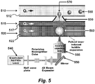
- FIG. 5 Another illustrative embodiment is shown in Figure 5 .
- the figure shows a device, which can be a microfluidic device, comprising a first fluid channel (520) (e.g., a microchannel) containing a first fluid (522), a second fluid channel (515) (e.g., a microchannel) containing a second fluid (517), and a third fluid channel (510) (e.g., a microchannel) containing a third fluid (512) where the second fluid is immiscible in the third fluid and where the second fluid channel and the third fluid channel are in fluid communication with each other via an opening (530).
- this opening is in the form of a nozzle.
- the second fluid may include particles or cells (516) that may be subsequently encapsulated in the generated fluid droplet, and can be in fluid communication with the first fluid channel (520) via an aperture (535) or similar structure.
- a directed energy source (540) for example a pulse laser, is directed towards the first fluid channel (520), optionally using a mirror (550), and directed (and optionally focused) into a volume of the first fluid channel (520) using, for example, a lens (555).
- the mirror and/or the lens are configured to permit focusing of the directed energy source at different positions within the first fluid channel (520).
- the directed energy source (540) initiates the formation of a transient bubble (560) (e.g., a cavitation bubble) within the first fluid channel (520), driving a droplet of the second fluid (570) into the third fluid channel (510). Collapse of the bubble causes a back flow of the extruded second fluid, causing the formation of a narrow "neck” and quickly leading to the release the droplet (580) into the third fluid channel (510).
- a transient bubble e.g., a cavitation bubble
- FIG. 6 Another embodiment of the invention is shown in Figure 6 .
- the figure shows a device, which can be a microfluidic device, comprising a first fluid channel (620) (e.g., a microchannel) containing a first fluid (622), a second fluid channel (615) (e.g., a microchannel) containing a second fluid (617), and a third fluid channel (610) (e.g., a microchannel) containing a third fluid (612) where the second fluid is immiscible in the third fluid and where the second fluid channel and the third fluid channel are in fluid communication with each other via an opening (630).
- this opening is in the form of a nozzle.
- a flexible membrane (635) is interposed between the first fluid channel (620) and the second fluid channel (615).
- a directed energy source (640) for example a pulse laser, is directed towards the first fluid channel (520), optionally using a mirror (650) and focused into a volume of the first fluid channel (620) optionally using a lens (655).
- the mirror and/or the lens are configured to permit focusing of the directed energy source at different positions within the first fluid channel (620).
- the directed energy source (640) initiates the formation of a transient bubble (660) (e.g., a cavitation bubble) within the first fluid channel (620), which results in an elastic deformation of the flexible membrane (635).
- This elastic deformation drives a droplet of the second fluid (670) into the third fluid channel (610). Reversal of the elastic deformation following collapse of the bubble (660) results in a back flow of the extruded second fluid, causing the formation of a narrow "neck” and quickly leading to the release the droplet (680) into the third fluid channel (610). Response time of this configuration can be controlled by the stiffness of the elastic membrane in addition to the other parameters discussed above.
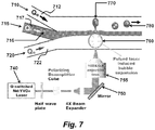
- FIG. 7 shows a device, which can be a microfluidic device, comprising a first fluid channel (720) (e.g., a microchannel) containing a first fluid (720), a second fluid channel (715) (e.g., a microchannel) containing a second fluid (717), and a third fluid channel (710) (e.g., a microchannel) containing a third fluid (712) wherein the first, second, and third fluids are immiscible (e.g ., by virtue of laminar flow and/or chemical immiscibility).
- the second fluid may include particles or cells (716) that may be subsequently encapsulated in the generated fluid droplet.
- a directed energy source (740), for example a pulse laser, is directed towards the first fluid channel (720), optionally using a mirror (750), and focused into a volume of the first fluid channel (720), optionally using a lens (755).
- the mirror and/or the lens are configured to permit focusing of the directed energy source at different positions within the first fluid channel (720).
- the directed energy source (740) initiates the formation of a transient bubble (760) (e.g., a cavitation bubble) within the first fluid channel (720), driving a droplet of the second fluid (770) into the third fluid channel (710). Collapse of the bubble causes a back flow of the extruded second fluid, causing the formation of a narrow "neck” and quickly leading to the release the droplet (780) into the third fluid channel (710).
- a transient bubble e.g., a cavitation bubble
- a pulse laser as a directed energy source
- other energy sources are suitable for use with the invention.
- Alternative directed energy sources include non-laser, high output optical sources (e.g . focused arc lamps), microwave irradiation, inductive heating, and acoustic energy (e.g . ultrasound).
- pulsed lasers are preferred energy sources. Lasers are advantageous in that they do not require any electrical or mechanical wiring or interconnects to deliver energy. A laser beam can be focused to any arbitrary 3D location across a transparent substrate. This eliminates the interfacing problems and facilitates the integration on standard foundry microfluidic chips.
- Illustrative lasers include, but are not limited to nanosecond pulsed laser with a wavelength, for example, at 532 nm. Microsecond, picosecond or femtosecond pulse lasers, and the like, can also be applied. In certain embodiments the wavelength of laser can also in the UV, visible light, or near infrared.
- the devices or systems comprising the devices can incorporate a monitoring device that characterizes the contents of one or more of the fluid channels.
- Data from this monitoring device can be transmitted to a controller, which in turn may be configured to trigger the directed energy source based on data received from the monitor.
- a fluorescence monitor may by aligned with a fluid channel that contains fluorescently labeled cells or particles.
- the controller can initiate a laser pulse that results in the formation of a droplet that encapsulates the desired cell.
- absorbance may be used to differentiate contents of a monitored fluid stream.
- Monitors are not limited to fluorescence or absorbance monitors.
- magnetic monitors, capacitance monitors, inductance monitors, electrochemical monitors can similarly be used to advantage.
- one or more of the fluid streams may be confined within physical channels (e.g., microchannels), the fluid streams need not be constrained or separated by a physical barrier/channel wall.
- fluid streams can be confined and/or separated, and/or directed along predetermined paths by variations in the polarity/hydrophobicity/surface free energy of the surface upon which they are disposed ( see, e.g., Zhao et al. (2002) Anal.
- the fluid streams are microfluid streams.
- a "microfluid stream” refers to a stream wherein at least about 40%, or at least about 50%, , or at least about 60%" or at least about 70%” or at least about 80%" or at least about 90%” or at least about 95%” or at least about 98%, or at least about 99%, of the flux or mass of said fluid stream passes through a cross-sectional area having at least one characteristic dimension (e.g., width or diameter) less than 1,000 ⁇ m, more preferably less than about 900 ⁇ m, or less than about 800 ⁇ m, or less than about 700 ⁇ m, or less than about 600 ⁇ m, or less than about 500 ⁇ m, or less than about 400 ⁇ m, or less than about 300 ⁇ m, or less than about 250 ⁇ m, or less than about 200 ⁇ m, or less than about 150 ⁇ m, or less than about 100 ⁇ , or less than about 75 ⁇ , or less than about 50 ⁇ m, or less than about 40
- one or more of the fluid streams are disposed in a channel or a microchannel.
- microfluidic channel or “microchannel” are used interchangeably and refer to a channel having at least one characteristic dimension (e.g., width or diameter) less than 1,000 ⁇ , more preferably less than about 900 ⁇ m, or less than about 800 ⁇ m, or less than about 700 ⁇ m, or less than about 600 ⁇ m, or less than about 500 ⁇ m, or less than about 400 ⁇ m, or less than about 300 ⁇ m, or less than about 250 ⁇ m, or less than about 200 ⁇ m, or less than about 150 ⁇ m, or less than about 100 ⁇ m, or less than about 75 ⁇ m, or less than about 50 ⁇ m, or less than about 40 ⁇ , or less than about 30 ⁇ m, or less than about 20 ⁇ m.
- characteristic dimension e.g., width or diameter
- the methods and devices described herein may utilize immiscible fluids.
- immiscible when used with respect to two fluids indicates that the fluids when mixed in some proportion, do not form a solution.
- Classic immiscible materials are water and oil.
- Immiscible fluids, as used herein also include fluids that substantially do not form a solution when combined in some proportion. Commonly the materials are substantially immiscible when they do not form a solution if combined in equal proportions.
- immiscible fluids include fluids that are not significantly soluble in one another, fluids that do not mix for a period of time due to physical properties such as density or viscosity, and fluids that do not mix for periods of time due to laminar flow.
- such fluids are not restricted to liquids but may include liquids and gases.
- an aqueous solvent such as water
- any number of organic compounds such as carbon tetrachloride, chloroform, cyclohexane, 1,2-dichloroethane, dichloromethane, diethyl ether, dimethyl formamide, ethyl acetate, heptane, hexane, methyl-tert-butyl ether pentane, toluene, 2,2,4-trimethylpentane, and the like are contemplated.
- Various mutually insoluble solvent systems are well known to those skilled in the art (see e.g. Table 1).
- droplets of aqueous buffer containing physiologically normal amounts of solute may be produced in a dense aqueous buffer containing high concentrations of sucrose.
- droplets of an aqueous buffer containing physiologically normal amounts of solute may be produced in a second aqueous buffer containing physiologically normal amounts of solute where the two buffers are segregated by laminar flow.
- droplets of a fluid may be produced in a gas such as nitrogen or air.
- Table 1 illustrates various solvents that are either miscible or immiscible in each other. The solvent on left column does not mix with solvents on right column unless otherwise stated.
- Acetone can be mixed with any of the solvents listed in the column at left Acetonitrile cyclohexane, heptane, hexane, pentane, 2,2,4-trimethylpentane carbon tetrachloride can be mixed with any of the solvents listed in the column at left except water chloroform can be mixed with any of the solvents listed in the column at left except water cyclohexane acetonitrile, dimethyl formamide, dimethyl sulfoxide, methanol, water 1,2-dichloroethane can be mixed with any of the solvents listed in the column at left except water dichloromethane can be mixed with any of the solvents listed in the column at left except water diethyl ether dimethyl sulfoxide, water dimethyl formamide cyclohexane, heptane, hexane, pentane, 2,2,4-trimethylpentane, water dimethyl solfoxide cyclohe
- first fluid and second fluid need not be immiscible in each other.
- injected droplets can be kept separate from each other simply by adjusting flow rates in the microchannels and rate of bubble formation to form separated bubbles.
- the droplets generated by the devices and methods described herein can contain or encapsulate a wide variety of materials.
- the droplets may contain test samples, cells, organelles, proteins, nucleic acids, enzymes, PCR or other testing reagents, biochemicals, dyes, or particulates (for example polymeric microspheres, metallic microparticles, or pigments).
- a droplet may encapsulate one or more previously generated droplets.
- the invention need not be limited to aqueous droplet systems.
- such droplet generating methods and devices may be used in nanoparticle coating, where materials in organic solvents can be used to deposit layers on or encapsulate nanoparticles.
- an opening in a fluid channel can be configured as a nozzle.
- the depth, inner diameter, and outer diameter of such a nozzle can be optimized to control droplet size, droplet uniformity, mixing at the fluid interface, or a combination of these.
- the droplet generation devices described herein may be provided on a substrate that differs from the material that comprises the fluid channels.
- the fluid channels may be fabricated using an elastomeric material that is disposed upon a rigid surface.
- Suitable fluid channel materials include but are not limited to flexible polymers such as PDMS, plastics, and similar materials. Fluid channels may also be comprised of nonflexible materials such as rigid plastics, glass, silicon, quartz, metals, and similar material.
- Suitable substrates include but are not limited to transparent substrates such as polymers, plastic, glass, quartz, or other dielectric materials. Other suitable substrate materials include but are not limited to nontransparent materials such as opaque or translucent plastics, silicon, metal, ceramic, and similar materials.
- the droplet generating devices and the connecting fluid channels are comprised of PDMS (or other polymers), and fabricated using soft lithography.
- PDMS is an attractive material for a variety of reasons, including but not limited to low cost, optical transparency, ease of molding, and elastomeric character.
- PDMS also has desirable chemical characteristics, including compatibility with both conventional siloxane chemistries and the requirements of cell culture (e.g. low toxicity, gas permeability).
- a master mold is prepared to form the fluid channel system.
- This master mold may be produced by a micromachining process, a photolithographic process, or by any number of methods known to those with skill in the art. Such methods include, but are not limited to, wet etching, electron-beam vacuum deposition, photolithography, plasma enhanced chemical vapor deposition, molecular beam epitaxy, reactive ion etching, and/or chemically assisted ion beam milling ( Choudhury (1997) The Handbook of Microlithography, Micromachining, and Microfabrication, Soc. Photo-Optical Instru. Engineer. ; Bard & Faulkner, Fundamentals of Microfabrication ).
- the master mold is exposed to a pro-polymer, which is then cured to form a patterned replica in PDMS.
- the replica is removed from the master mold, trimmed, and fluid inlets are added where required.
- the polymer replica may be optionally be treated with a plasma (e.g. an O 2 plasma) and bonded to a suitable substrate, such as glass.
- a plasma e.g. an O 2 plasma
- O 2 plasma oxygen-s
- Treatment of PDMS with O 2 plasma generates a surface that seals tightly and irreversibly when brought into conformal contact with a suitable substrate, and has the advantage of generating fluid channel walls that are negatively charged when used in conjunction with aqueous solutions.
- These fixed charges support electrokinetic pumping that may be used to move fluid through the device.
- single layer devices are contemplated.
- multilayer devices are contemplated.
- a multilayer network of fluid channels may be designed using a commercial CAD program. This design may be converted into a series of transparencies that is subsequently used as a photolithographic mask to create a master mold. PDMS cast against this master mold yields a polymeric replica containing a multilayer network of fluid channels. This PDMS cast can be treated with a plasma and adhered to a substrate as described above.
- the fluid channels are microchannels.
- Such microchannels have characteristic dimensions ranging from about 100 nanometers to 1 micron up to about 500 microns. In various embodiments the characteristic dimension ranges from about 1, 5, 10, 15, 20, 25, 35, 50 or 100 microns up to about 150, 200, 250, 300, or 400 microns. In some embodiments the characteristic dimension ranges from about 20, 40, or about 50 microns up to about 100, 125, 150, 175, or 200 microns.
- the wall thickness between adjacent fluid channels ranges from about 0.1 micron to about 50 microns, or about 1 micron to about 50 microns, more typically from about 5 microns to about 40 microns. In certain embodiments the wall thickness between adjacent fluid channels ranges from about 5 microns to about 10, 15, 20, or 25 microns.
- the depth of a fluid channel ranges from 5, 10, 15, 20 microns to about 1mm, 800 microns, 600 microns, 500 microns, 400 microns, 300 microns, 200 microns, 150 microns, 100 microns, 80 microns, 70 microns, 60 microns, 50 microns, 40 microns, or about 30 microns. In certain embodiments the depth of a fluid channel ranges from about 10 microns to about 60 microns, more preferably from about 20 microns to about 40 or 50 microns. In some embodiments the fluid channels can be open; in other embodiments the fluid channels may be covered.
- the nozzle diameter can range from about 0.1 micron, or about 1 micron up to about 300 microns, 200 microns, or about 100 microns. In certain embodiments the nozzle diameter can range from about 5, 10, 15, or 20 microns up to about 25, 30, 35, 40, 45, 50, 55, 60, 65, 70, 75, or about 80 microns. In some embodiments the nozzle diameter ranges from about 1, 5, 10, 15, or 20 microns to about 25, 35, or 40 microns.
- the methods and devices described herein can generate droplets at a rate ranging from zero droplets/sec, about 2 droplets/sec, about 5 droplets/sec, about 10 droplets/sec, about 20 droplets/sec, about 50 droplets/sec, about 100 droplets/sec, about 500 droplets/sec, or about 1000 droplets/sec, up to about 1,500 droplets/sec, about 2,000 droplets/sec, about 4,000 droplets/sec, about 6,000 droplets/sec, about 8,000 droplets/sec, about 10,000 droplets/sec, about 20,000 droplets/sec, about 50,000 droplets/sec, and about 100,000 droplets/sec.
- the devices and methods described herein can generate droplets having a substantially continuous volume.
- Droplet volume can be controlled to provide volumes ranging from about 0.1fL, about 1fL, about 10 fL, and about 100 fL to about 1 microliter, about 500 nL, about 100nL, about 1 nL, about 500 pL or about 200 pL.
- volume control of the droplet ranges from about 1 pL to about 150 pL, about 200 pL, about 250 pL, or about 300 pL.
- microchannel droplet formation/injection devices described herein can provide a system integrated with other processing modules on a microfluidic "chip” or in flow through fabrication systems for microparticle coating, microparticle drug carrier formulation, and the like. These uses, however, are merely illustrative and not limiting.
- microfluidic that incorporate components/modules/devices that performing the methods described herein can can manipulate volumes as small as one to several nanoliters. Because the microfluidic reaction volume is close to the size of single mammalian cells, material loss is minimized in single-cell mRNA analysis with these devices. The ability to process live cells inside microfluidic devices provides a great advantage for the study of single-cell transcriptomes because mRNA is rapidly degraded with cell death.
- One illustrative highly integrated microfluidic device having 26 parallel 10 nL reactors for the study of gene expression in single human embryonic stem cells (hESC) has been reported ( Zhong et al. (2008) Lab on a Chip, 8: 68-74 ; Zhong et al.
- microfluidic devices include systems for obtaining single-cell cDNA including cell capture, mRNA capture/purification, cDNA synthesis/purification, are performed inside the device.
- the present devices and methods offer effective means of encapsulating and and/or separating individual cells for, e.g., further processing, in such devices.
- any of a number of approaches can be used to convey the fluids, or mixtures of droplets, particles, cells, etc. along the flow paths and/or channels of the devices described herein.
- Such approaches include, but are not limited to gravity flow, syringe pumps, peristaltic pumps, electrokinetic pumps, bubble-driven pumps, and air pressure driven pumps.
- a pulse laser-driven droplet generation (PLDG) device as shown in Figure 3 was constructed using standard soft lithography techniques.
- the PLDG device had two fluid channels, one filled with water and the other with oil. Both fluid channels were 100 microns in width and 100 microns in height.
- the fluid channels were connected with an opening configured as a nozzle, with a neck that was 30 microns in width. Flow rates in the channels were adjusted to produce a stable oil/water interface.
- this PLDG device was based on a laser pulse-induced cavitation bubble, generated when an intense laser pulse was focused into the water containing fluid channel. Plasma formation at the focal point of the laser pulse generates a rapidly expanding cavitation bubble, as described above. This perturbs the oil/water interface and pushes a droplet of water into the neighboring oil-filled fluid channel to from stable water droplets. The lifetime of this cavitation bubble ranged from tens to hundreds of microseconds in these studies.
- a Q-switched Nd:YVO4 pulsed laser beam with a wavelength of 532nm, a 15 nsec pulse width, and a maximum repetition frequency of 100KHz was focused through a 100X objective lens into the PLDG device.
- Other wavelengths, such as UV, visible, and infrared may also be suitable.
- Droplet generation was captured using a time resolved imaging system.
- Figure 8 shows a series of such images obtained during droplet generation. Using corn oil for a continuous oil phase and phosphate buffered saline (PBS) for an aqueous phase, corn oil and PBS flow rates were adjusted to form a stable interface at the nozzle opening ( Figure 8 , panel (a)).
- PBS phosphate buffered saline
- Cavitation bubble formation is initiated within 1 microsecond of the initiating laser pulse ( Figure 8 panel (b)) and reaches maximum size within 3 microseconds, pushing PBS into the corn oil channel ( Figure 8 , panel (c)).
- the bubble begins to collapse after 5 microseconds ( Figure 8 , panel (d)).
- As the cavitation bubble collapses a narrow neck is formed between the PBS fluid channel and the extruded droplet ( Figures 8 , panels (d) to (f)).
- This connection severs due to hydrodynamic instability ( Figure 8 , panel (g)).
- a 137 pL droplet was generated using a 100 microjoule laser pulse in about 500 microseconds, then transported away by flow through the corn oil channel ( Figure 8 , panels (h) and (i)8H).
- the volume of PLDG can be controlled can be controlled by adjusting the energy delivered by the pulse laser, which is a function of laser intensity and pulse duration, the location of the laser excitation, or a combination of the above.
- the energy of the pulse laser may be adjusted using a beam polarizer.
- Figure 9 illustrates control of the volume of droplets produced by PLDG by adjusting these parameters.
- Control of droplet size is shown in Figure 9 in panels (e) to (g), where laser energy is held constant at 100 microjoules and the distance of the focus point to the nozzle is adjusted between about 40 microns and about 80 microns. Droplet size decreases from about 60 microns to about 25 microns as the focus point is moved away from the corn oil/PBS interface. Using a combination of laser energy and focal point distance from the fluid interface droplet volume can be controlled between 1 pL to 150 pL.
- FIG 10 shows the results of continuous droplet generation at different excitation intervals ranging from 2 msec ( Figure 10 , panel (a)) to 100 microseconds ( Figure 10 , panel (d)). The flow rate of the fluid channel receiving the droplets was adjusted to keep the droplets dispersed at high droplet generation rates.
- Figure 11 shows illustrative e droplets collected at droplet generation frequencies of 1kHz (panel (a)) and 10 kHz (panel (b)). Droplet size was consistent despite a 10 fold difference in the rate at which the droplets are formed.
- Figure 12 shows results from a similar study, in which the interval between laser excitations was set at 2 msec (panel (a)), 500 microseconds (panel (b)), and 100 microseconds (panel (c)). Data collected from droplets generated at 500 microsecond intervals (2kHz) showed a volume variation of 0.689%.
- PLDG permits the encapsulation of specified contents of a fluid channel as droplets in a second fluid channel.
- An example of such an application is the encapsulation of a single particle or cell designated from a stream of particles or cells passing through a PLDG device, as directed by a controller based on data received from a monitor. Such a particle or cell could be isolated within a droplet of growth media and carried by a second fluid channel for further characterization.
- FIG. 13 This is shown in Figure 13 .
- panel (a) particles (indicated by white arrows) are shown in s fluid channel of a PLDG device.
- Generation of the encapsulating droplet is shown in Figure 13 , panel (b).
- the droplet seen extruding through the nozzle at 250 microseconds from induction of the cavitation bubble can be seen to enclose a particle.
- Figure 13 , panel (c) shows results of a similar study, with continuous capture of cells. Encapsulation of live HeLa cells in this fashion shows high viability rates (92.07%).
- PLDG device reliability has been tested by continuously applying laser pulses at a rate of 10 kHz for one hour, corresponding to the generation of 3.6 million cavitation bubble generations with no observable damage to the device.
- Droplet generation methods and devices that are particularly suited to use in microfluidic devices have been disclosed. These provide for rapid, on demand droplet generation at rates as high as 100 kHz. Droplet volume can be adjusted and has been shown to be highly reproducible, with volume differences of less than 1%.
- the disclosed devices do not utilize mechanical parts, and the use of an externally located directed energy source (for example a pulse laser) greatly simplifies design of both the device and supporting equipment. It should also be noted that the efficiency and inherent simplicity of the PLDG approach may have utility outside of the field of microfluidics. The high rate of droplet production and the narrow size distribution of the resulting droplets indicate that such methods and devices may have utility in the preparation of emulsions where consistency of the droplet size is paramount.
- Examples include but are not limited to pharmaceuticals, including vaccine compositions.
- the high rate of droplet production and the ability to control the volume of droplets as they are extruded indicate that such methods and devices may have utility in the deposition of generated droplets across a fluid/gas interface and onto solid surfaces, thereby depositing and localizing nonvolatile droplet contents. Examples of such uses include but are not limited to high resolution printing and generation of microarrays. It should be apparent, however, to those skilled in the art that many more modifications besides those already described are possible without departing from the inventive concepts herein
Landscapes
- Chemical & Material Sciences (AREA)
- Health & Medical Sciences (AREA)
- Dispersion Chemistry (AREA)
- Physics & Mathematics (AREA)
- General Health & Medical Sciences (AREA)
- Chemical Kinetics & Catalysis (AREA)
- Analytical Chemistry (AREA)
- Organic Chemistry (AREA)
- Hematology (AREA)
- Clinical Laboratory Science (AREA)
- General Physics & Mathematics (AREA)
- Life Sciences & Earth Sciences (AREA)
- Biochemistry (AREA)
- Immunology (AREA)
- Pathology (AREA)
- Optics & Photonics (AREA)
- Fluid Mechanics (AREA)
- Engineering & Computer Science (AREA)
- Automation & Control Theory (AREA)
- Electromagnetism (AREA)
- Toxicology (AREA)
- Nuclear Medicine, Radiotherapy & Molecular Imaging (AREA)
- Physical Or Chemical Processes And Apparatus (AREA)
- Apparatus Associated With Microorganisms And Enzymes (AREA)
- Micromachines (AREA)
- Immobilizing And Processing Of Enzymes And Microorganisms (AREA)
- Measuring Or Testing Involving Enzymes Or Micro-Organisms (AREA)
- Automatic Analysis And Handling Materials Therefor (AREA)
Claims (16)
- Verfahren zum Erzeugen von Tröpfchen in einer Vorrichtung, das Folgendes umfasst
Bereitstelleneiner ersten Fluidbahn (620), umfassend ein erstes Fluid (622);einer zweiten Fluidbahn (615), umfassend ein zweites Fluid (617); undeiner dritten Fluidbahn (610), umfassend ein drittes Fluid (612); undErzeugen einer Kavitationsblase (660) in der ersten Fluidbahn (620), wobei die Kavitationsblase (660) einem Teil des zweiten Fluids (617) eine ausreichende Geschwindigkeit vermittelt, um ein Tröpfchen, umfassend ein kontrolliertes Volumen (670) des zweiten Fluids (617), in die dritte Fluidbahn (610) auszustoßen;
dadurch gekennzeichnet, dass
eine flexible Membran (635) zwischen der ersten Fluidbahn (620) und der zweiten Fluidbahn (615) eingefügt ist, eine Öffnung (630) zwischen der zweiten Fluidbahn (615) und der dritten Fluidbahn (610) bereitgestellt ist, und der Schritt des Erzeugens einer Kavitationsblase (660) in der ersten Fluidbahn (620) einen Teil der flexiblen Membran (635) elastisch in die zweite Fluidbahn (615) verformt, wobei die elastische Verformung des Teiles der flexiblen Membran (635) eine ausreichende Geschwindigkeit an einen Teil des zweiten Fluids (617) vermittelt, um das Tröpfchen (670) des zweiten Fluids (617) über die Öffnung (630) hinweg und in die Fluidbahn (610) auszustoßen. - Verfahren nach Anspruch 1, wobei die Kavitationsblase eine Dauer von 1 Millisekunde oder weniger hat.
- Verfahren nach Anspruch 1 oder 2, wobei die Kavitationsblase (660) durch Bestrahlung eines Volumens des ersten Fluids erzeugt wird.
- Verfahren nach Anspruch 3, wobei die Bestrahlung durch eine Steuerung initiiert wird.
- Verfahren nach Anspruch 4, wobei die Bestrahlung ein Laser (640)-Impuls ist.
- Verfahren nach Anspruch 5, ferner umfassend einen Schritt des Auswählens von mindestens einem von dem Timing des Auftretens von Impulsen, die von dem Pulslaser emittiert werden, der Häufigkeit des Auftretens von Impulsen, die von dem Pulslaser emittiert werden, der Wellenlänge von Impulsen, die von dem Pulslaser emittiert werden, der Energie von Impulsen, die von dem Pulslaser emittiert werden und dem Ausrichten oder Ort von Impulsen, die von dem Pulslaser emittiert werden.
- Verfahren nach einem der vorhergehenden Ansprüche, wobei das zweite Fluid (617) und das dritte Fluid (612) nicht mischbare Fluide sind.
- Verfahren nach einem der vorhergehenden Ansprüche, wobei das zweite Fluid (617) ferner ein Partikel oder eine Zelle umfasst, wobei das ausgestoßene Tröpfchen das Partikel oder die Zelle enthält.
- Vorrichtung zum Erzeugen von Tröpfchen, umfassend:eine erste Fluidbahn (620);eine zweite Fluidbahn (615);eine dritte Fluidbahn (610);eine Steuerung, die funktionsfähig konfiguriert ist, um eine Energie zu lenken, die eine temporäre Bildung einer Kavitationsblase (660) in einem ersten Fluid (622) in der ersten Fluidbahn (620) induziert, wobei die Kavitationsblase (660) eine ausreichende Geschwindigkeit an einen Teil eines zweiten Fluids (617) in der zweiten Fluidbahn (615) vermittelt, um ein Tröpfchen (670) des zweiten Fluids (617) in die dritte Fluidbahn (610), die ein drittes Fluid (612) umfasst, auszustoßen;dadurch gekennzeichnet, dassdie Vorrichtung eine flexible Membran (635) umfasst, die zwischen der ersten Fluidbahn (620) und der zweiten Fluidbahn (615) eingefügt ist, wobei die flexible Membran (635) so angeordnet ist, dass die Bildung der Blase (660) im ersten Fluid (622) in der ersten Fluidbahn (620) eine Kraft induziert, die einen Teil der flexiblen Membran (635) elastisch verformt; und eine Öffnung (63) zwischen der zweiten Fluidbahn (615) und der dritten Fluidbahn (610) umfasst, wobei die Öffnung (630) so angeordnet ist, dass eine elastische Verformung eines Teiles der flexiblen Membran (635) eine Kraft auf das zweite Fluid (617) induziert, um dadurch das Tröpfchen (670) des zweiten Fluids (617) aus der zweiten Fluidbahn (615) durch die Öffnung (630) in die dritte Fluidbahn (610) auszustoßen.
- Vorrichtung nach Anspruch 9, wobei die Vorrichtung konfiguriert ist, um Kavitationsblasen bereitzustellen, die eine Dauer von 1 Millisekunde oder weniger haben.
- Vorrichtung nach Anspruch 9 oder 10, ferner umfassend einen Pulslaser (640), der von der Steuerung zur Bestrahlung eines Volumens des ersten Fluids initiiert werden soll, um eine Kavitationsblase (660) zu erzeugen.
- Vorrichtung nach einem der Ansprüche 9 bis 11, wobei die Steuerung es ermöglicht, die Energie bei einem programmierbaren Timing zu lenken.
- Vorrichtung nach einem der Ansprüche 9 bis 12, wobei die Steuerung mindestens eines von dem Timing des Auftretens von Impulsen, die von dem Pulslaser emittiert werden, der Häufigkeit des Auftretens von Impulsen, die von dem Pulslaser emittiert werden, der Wellenlänge von Impulsen, die von dem Pulslaser emittiert werden, der Energie von Impulsen, die von dem Pulslaser emittiert werden und dem Ausrichten oder Ort von Impulsen, die von dem Pulslaser emittiert werden.
- Vorrichtung nach einem der Ansprüche 9 bis 13, ferner umfassend einen Monitor, der konfiguriert ist, um die zweite oder dritte Fluidbahn zu überwachen und ferner konfiguriert ist, um Daten vom Monitor zur Steuerung zu übertragen.
- Vorrichtung nach Anspruch 14, wobei die Steuerung ferner konfiguriert sein kann, ein bezeichnetes Volumen des zweiten Fluids in die dritte Fluidbahn zu steuern, wobei das bezeichnete Volumen mindestens teilweise durch Daten vom Monitor festgelegt ist.
- Verfahren nach einem der Ansprüche 1-8 oder Vorrichtung nach einem der Ansprüche 9-15, wobei das Verfahren eine Tröpfchenerzeugung bei einer Frequenz von bis zu 100 kHz mit einer Tröpfchenvolumendifferenz von weniger als 1 % produziert oder die Vorrichtung konfiguriert ist, eine Tröpfchenerzeugung bei einer Frequenz von bis zu 100 kHz mit einer Tröpfchenvolumendifferenz von weniger als 1 % zu produzieren.
Priority Applications (1)
| Application Number | Priority Date | Filing Date | Title |
|---|---|---|---|
| EP18178872.0A EP3410124B1 (de) | 2012-02-09 | 2013-02-08 | Schnelle on-demand-erzeugung von tröpfchen und durch induzierte kavitation angesteuerte einzelzellenverkapselung |
Applications Claiming Priority (2)
| Application Number | Priority Date | Filing Date | Title |
|---|---|---|---|
| US13/370,196 US9176504B2 (en) | 2011-02-11 | 2012-02-09 | High-speed on demand droplet generation and single cell encapsulation driven by induced cavitation |
| PCT/US2013/025434 WO2013120016A2 (en) | 2012-02-09 | 2013-02-08 | High-speed on demand droplet generation and single cell encapsulation driven by induced cavitation |
Related Child Applications (2)
| Application Number | Title | Priority Date | Filing Date |
|---|---|---|---|
| EP18178872.0A Division EP3410124B1 (de) | 2012-02-09 | 2013-02-08 | Schnelle on-demand-erzeugung von tröpfchen und durch induzierte kavitation angesteuerte einzelzellenverkapselung |
| EP18178872.0A Division-Into EP3410124B1 (de) | 2012-02-09 | 2013-02-08 | Schnelle on-demand-erzeugung von tröpfchen und durch induzierte kavitation angesteuerte einzelzellenverkapselung |
Publications (3)
| Publication Number | Publication Date |
|---|---|
| EP2812709A2 EP2812709A2 (de) | 2014-12-17 |
| EP2812709A4 EP2812709A4 (de) | 2016-01-27 |
| EP2812709B1 true EP2812709B1 (de) | 2018-08-01 |
Family
ID=50686259
Family Applications (2)
| Application Number | Title | Priority Date | Filing Date |
|---|---|---|---|
| EP18178872.0A Active EP3410124B1 (de) | 2012-02-09 | 2013-02-08 | Schnelle on-demand-erzeugung von tröpfchen und durch induzierte kavitation angesteuerte einzelzellenverkapselung |
| EP13746888.0A Active EP2812709B1 (de) | 2012-02-09 | 2013-02-08 | Schnelle on-demand-erzeugung von tröpfchen und durch induzierte kavitation angesteuerte einzelzellenverkapselung |
Family Applications Before (1)
| Application Number | Title | Priority Date | Filing Date |
|---|---|---|---|
| EP18178872.0A Active EP3410124B1 (de) | 2012-02-09 | 2013-02-08 | Schnelle on-demand-erzeugung von tröpfchen und durch induzierte kavitation angesteuerte einzelzellenverkapselung |
Country Status (9)
| Country | Link |
|---|---|
| US (2) | US9176504B2 (de) |
| EP (2) | EP3410124B1 (de) |
| JP (2) | JP6367717B2 (de) |
| KR (1) | KR20150016929A (de) |
| CN (2) | CN106732223B (de) |
| AU (2) | AU2013216804B2 (de) |
| CA (1) | CA2864138C (de) |
| ES (2) | ES2832486T3 (de) |
| WO (1) | WO2013120016A2 (de) |
Families Citing this family (57)
| Publication number | Priority date | Publication date | Assignee | Title |
|---|---|---|---|---|
| US9364831B2 (en) | 2009-08-08 | 2016-06-14 | The Regents Of The University Of California | Pulsed laser triggered high speed microfluidic switch and applications in fluorescent activated cell sorting |
| US9176504B2 (en) | 2011-02-11 | 2015-11-03 | The Regents Of The University Of California | High-speed on demand droplet generation and single cell encapsulation driven by induced cavitation |
| US10564147B2 (en) | 2012-05-25 | 2020-02-18 | The Regents Of The University Of California | Microfluidic systems for particle trapping and separation using cavity acoustic transducers |
| US9103468B2 (en) * | 2012-07-30 | 2015-08-11 | University Of South Carolina | Enhanced flow boiling in microchannels by high frequency microbubble-excited and -modulated oscillations |
| US9731293B2 (en) * | 2012-10-03 | 2017-08-15 | The United States Of America, As Represented By The Secretary Of The Navy | Paired laser and electrokinetic separation, manipulation, and analysis device |
| US20140151229A1 (en) | 2012-12-05 | 2014-06-05 | Caliper Life Sciences, Inc. | Manipulation of objects in microfluidic devices using external electrodes |
| US9297784B2 (en) | 2012-12-05 | 2016-03-29 | Caliper Life Sciences, Inc. | Device and method for extracting target objects from a sample |
| US9995412B2 (en) * | 2013-03-01 | 2018-06-12 | Wave 80 Biosciences, Inc. | Long-throw microfluidic actuator |
| CN105452873B (zh) * | 2013-03-15 | 2019-01-18 | 加利福尼亚大学董事会 | 高速按需微流体珠滴生成和操控 |
| EP2848698A1 (de) * | 2013-08-26 | 2015-03-18 | F. Hoffmann-La Roche AG | System und Methode zur automatisierten Nukleinsäure-Amplifikation |
| CN103614290B (zh) * | 2013-11-11 | 2015-03-04 | 北京工业大学 | 面向荧光pcr微系统的往复式循环单微通道装置 |
| US10960396B2 (en) | 2014-05-16 | 2021-03-30 | Cytonome/St, Llc | Thermal activated microfluidic switching |
| CA2890401C (en) | 2015-01-21 | 2015-11-03 | Vln Advanced Technologies Inc. | Electrodischarge apparatus for generating low-frequency powerful pulsed and cavitating waterjets |
| CA2984492A1 (en) | 2015-04-29 | 2016-11-03 | Flodesign Sonics, Inc. | Acoustophoretic device for angled wave particle deflection |
| CN104941702B (zh) * | 2015-05-25 | 2017-01-04 | 重庆大学 | 一种微通道内产生超小液滴的方法 |
| WO2017004676A1 (en) * | 2015-07-09 | 2017-01-12 | Monash University | On-demand single cell encapsulation using a localised acoustic field |
| US9862941B2 (en) | 2015-10-14 | 2018-01-09 | Pioneer Hi-Bred International, Inc. | Single cell microfluidic device |
| CA2921675C (en) | 2016-02-24 | 2017-12-05 | Vln Advanced Technologies Inc. | Electro-discharge system for neutralizing landmines |
| FR3049348B1 (fr) * | 2016-03-23 | 2023-08-11 | Commissariat Energie Atomique | Procede de caracterisation d’une particule dans un echantillon |
| WO2017165791A1 (en) * | 2016-03-25 | 2017-09-28 | President And Fellows Of Harvard College | Microfluidic determination of immune and other cells |
| US10228317B1 (en) * | 2016-08-25 | 2019-03-12 | Verily Life Sciences Llc | Multiplexed microfluidic cell sorting using laser induced cavitation bubbles |
| CN106190779B (zh) * | 2016-08-29 | 2018-08-24 | 苏州汶颢芯片科技有限公司 | 基于微流控芯片的单细胞分离和包封装置和方法 |
| WO2018071448A1 (en) | 2016-10-11 | 2018-04-19 | The Regents Of The University Of California | Systems and methods to encapsulate and preserve organic matter for analysis |
| US11911731B2 (en) | 2016-10-21 | 2024-02-27 | Hewlett-Packard Development Company, L.P. | Droplet generator |
| US10718004B2 (en) | 2016-12-20 | 2020-07-21 | Lawrence Livermore National Security, Llc | Droplet array for single-cell analysis |
| EP3558524A1 (de) * | 2016-12-22 | 2019-10-30 | IMEC vzw | Mikrofluidische vorrichtung zum aussortieren von tröpfchen |
| CN106890683B (zh) * | 2017-03-14 | 2019-03-08 | 广东工业大学 | 一种多层液滴包裹的形成方法 |
| EP3625353B1 (de) | 2017-05-18 | 2022-11-30 | 10X Genomics, Inc. | Verfahren und systeme zum sortieren von tröpfchen und perlen |
| US10544413B2 (en) | 2017-05-18 | 2020-01-28 | 10X Genomics, Inc. | Methods and systems for sorting droplets and beads |
| US11517901B2 (en) | 2017-06-09 | 2022-12-06 | The Regents Of The University Of California | High-efficiency particle encapsulation in droplets with particle spacing and downstream droplet sorting |
| WO2018227204A1 (en) * | 2017-06-09 | 2018-12-13 | The Regents Of The University Of California | Controlled encapsulation in droplets by liquid-liquid interfacial shearing |
| US10549279B2 (en) | 2017-08-22 | 2020-02-04 | 10X Genomics, Inc. | Devices having a plurality of droplet formation regions |
| WO2019075409A1 (en) | 2017-10-12 | 2019-04-18 | The Regents Of The University Of California | ISOLATION AND IDENTIFICATION WITHOUT MICROFLUIDIC LABEL OF CELLS USING FLUORESCENCE LIFE IMAGING (FLIM) |
| WO2019079787A1 (en) | 2017-10-20 | 2019-04-25 | The Regents Of The University Of California | MICROFLUIDIC SYSTEMS AND METHODS FOR CELL TRANSFECTION VIA LIPOFLEX |
| US11499127B2 (en) | 2017-10-20 | 2022-11-15 | The Regents Of The University Of California | Multi-layered microfluidic systems for in vitro large-scale perfused capillary networks |
| WO2019083852A1 (en) | 2017-10-26 | 2019-05-02 | 10X Genomics, Inc. | MICROFLUIDIC CHANNEL NETWORKS FOR PARTITIONING |
| CN108837778B (zh) * | 2018-06-05 | 2020-09-15 | 中南大学 | 一种制备核壳结构载药纳米粒的方法 |
| EP3613498A1 (de) * | 2018-08-24 | 2020-02-26 | Université de Liège | Mikrofluidisches modul zur co-einkapselung in tröpfchenform |
| CN109051819A (zh) * | 2018-08-27 | 2018-12-21 | 江苏大学 | 一种利用空泡输运颗粒的装置与方法 |
| CN108993342B (zh) * | 2018-09-06 | 2024-01-23 | 山东清创化工有限公司 | 一种管式反应器内光化学反应的微混合系统及方法 |
| CN109269762B (zh) * | 2018-10-16 | 2020-04-28 | 四川大学 | 利用同轴平行光源观测激光空泡冲击波的实验装置 |
| CN110346074A (zh) * | 2019-06-13 | 2019-10-18 | 江苏大学 | 一种测量激光诱导空泡溃灭冲击力的装置及方法 |
| CN110743635A (zh) * | 2019-10-27 | 2020-02-04 | 苏州济研生物医药科技有限公司 | 一种基于负压且无需流体剪切力的液滴生成装置 |
| CN111077487A (zh) * | 2019-12-03 | 2020-04-28 | 中广核工程有限公司 | 便携式核仪表系统信号检测及故障定位装置 |
| WO2021162700A1 (en) * | 2020-02-14 | 2021-08-19 | Hewlett-Packard Development Company, L.P. | Droplet delivery |
| CN111235029B (zh) * | 2020-03-09 | 2023-01-31 | 辽宁中医药大学 | 一种多功能微流控芯片及其制备方法与应用 |
| CN111495450B (zh) * | 2020-04-24 | 2021-04-06 | 清华大学 | 基于柱塞-叠片混合流的液-液-液三相流微流体芯片 |
| KR102491087B1 (ko) * | 2020-10-12 | 2023-01-19 | 인제대학교 산학협력단 | 정전용량형 전극을 이용한 액적 길이 측정장치 |
| WO2022148859A1 (en) | 2021-01-11 | 2022-07-14 | Vib Vzw | Means and methods for time-resolved sampling |
| US20220280941A1 (en) * | 2021-03-05 | 2022-09-08 | Enumerix, Inc. | Systems and methods for generating droplets and performing digital analyses |
| EP4351788A1 (de) | 2021-06-04 | 2024-04-17 | Enumerix, Inc. | Zusammensetzungen, verfahren und systeme zur einzelzellenbarcodierung und -sequenzierung |
| WO2022256612A1 (en) * | 2021-06-04 | 2022-12-08 | Enumerix, Inc. | Compositions, methods, and systems for single cell barcoding and sequencing |
| CN113654763A (zh) * | 2021-09-16 | 2021-11-16 | 中国科学院力学研究所 | 一种基于多种传感器的近壁面射流压力与速度测量的实验系统 |
| GB202113798D0 (en) | 2021-09-27 | 2021-11-10 | Univ Tartu | Microfluidics method |
| CN113967487B (zh) * | 2021-10-11 | 2022-12-02 | 华中科技大学 | 一种喷嘴、液滴光热操控系统及其应用 |
| US20230339226A1 (en) * | 2022-04-22 | 2023-10-26 | Bwxt Nog Technologies, Inc. | Drop-on-demand electroprinter with a plunging wire-in-a-nozzle |
| CN115364779A (zh) * | 2022-07-14 | 2022-11-22 | 南京信息工程大学 | 一种用于激光诱导击穿光谱的液态气溶胶发生装置 |
Family Cites Families (44)
| Publication number | Priority date | Publication date | Assignee | Title |
|---|---|---|---|---|
| JP2832117B2 (ja) * | 1991-11-29 | 1998-12-02 | キヤノン株式会社 | サンプル測定デバイス及びサンプル測定システム |
| US6143496A (en) * | 1997-04-17 | 2000-11-07 | Cytonix Corporation | Method of sampling, amplifying and quantifying segment of nucleic acid, polymerase chain reaction assembly having nanoliter-sized sample chambers, and method of filling assembly |
| US7214298B2 (en) | 1997-09-23 | 2007-05-08 | California Institute Of Technology | Microfabricated cell sorter |
| US6899137B2 (en) | 1999-06-28 | 2005-05-31 | California Institute Of Technology | Microfabricated elastomeric valve and pump systems |
| US6524456B1 (en) * | 1999-08-12 | 2003-02-25 | Ut-Battelle, Llc | Microfluidic devices for the controlled manipulation of small volumes |
| US20060128006A1 (en) * | 1999-11-10 | 2006-06-15 | Gerhardt Antimony L | Hydrodynamic capture and release mechanisms for particle manipulation |
| AU1592501A (en) | 1999-11-10 | 2001-06-06 | Massachusetts Institute Of Technology | Cell analysis and sorting apparatus for manipulation of cells |
| JP2001158099A (ja) * | 1999-12-02 | 2001-06-12 | Fuji Xerox Co Ltd | インクジェット記録ヘッド及びインクジェット記録装置 |
| US7351376B1 (en) | 2000-06-05 | 2008-04-01 | California Institute Of Technology | Integrated active flux microfluidic devices and methods |
| US7294503B2 (en) * | 2000-09-15 | 2007-11-13 | California Institute Of Technology | Microfabricated crossflow devices and methods |
| GB0105831D0 (en) | 2001-03-09 | 2001-04-25 | Toumaz Technology Ltd | Method for dna sequencing utilising enzyme linked field effect transistors |
| US6808075B2 (en) | 2002-04-17 | 2004-10-26 | Cytonome, Inc. | Method and apparatus for sorting particles |
| US7901939B2 (en) * | 2002-05-09 | 2011-03-08 | University Of Chicago | Method for performing crystallization and reactions in pressure-driven fluid plugs |
| JP3610349B2 (ja) * | 2002-08-06 | 2005-01-12 | キヤノン株式会社 | 液体搬送装置 |
| US7582482B2 (en) * | 2002-09-03 | 2009-09-01 | Dionex Corporation | Continuous ion species removal device and method |
| CN1261767C (zh) * | 2003-01-30 | 2006-06-28 | 财团法人工业技术研究院 | 低电压低功率热气泡薄膜式微流体驱动装置 |
| US20050031657A1 (en) | 2003-07-18 | 2005-02-10 | Gilson Michael K. | Hydrosomes; chemical vessels for laser-guided microfluidics |
| TW200523534A (en) * | 2003-09-04 | 2005-07-16 | Arryx Inc | Multiple laminar flow-based particle and cellular separation with laser steering |
| FR2873171B1 (fr) * | 2004-07-19 | 2007-12-07 | Centre Nat Rech Scient Cnrse | Circuit microfluidique a composant actif |
| US7759111B2 (en) | 2004-08-27 | 2010-07-20 | The Regents Of The University Of California | Cell encapsulation microfluidic device |
| US20060246575A1 (en) | 2005-01-13 | 2006-11-02 | Micronics, Inc. | Microfluidic rare cell detection device |
| JP4047336B2 (ja) | 2005-02-08 | 2008-02-13 | 独立行政法人科学技術振興機構 | ゲル電極付セルソーターチップ |
| FR2884437B1 (fr) | 2005-04-19 | 2007-07-20 | Commissariat Energie Atomique | Dispositif et procede microfluidique de transfert de matiere entre deux phases immiscibles. |
| US7918244B2 (en) * | 2005-05-02 | 2011-04-05 | Massachusetts Institute Of Technology | Microfluidic bubble logic devices |
| JP5114702B2 (ja) * | 2005-07-29 | 2013-01-09 | 国立大学法人 東京大学 | 両親媒性単分子膜の接触による二分子膜の形成方法およびその装置 |
| US7955864B2 (en) * | 2005-08-22 | 2011-06-07 | Life Technologies Corporation | Device and method for making discrete volumes of a first fluid in contact with a second fluid, which are immiscible with each other |
| FR2901717A1 (fr) * | 2006-05-30 | 2007-12-07 | Centre Nat Rech Scient | Procede de traitement de gouttes dans un circuit microfluidique. |
| US8465706B2 (en) | 2007-06-20 | 2013-06-18 | Trustees Of Columbia University In The City Of New York | On-demand microfluidic droplet or bubble generation |
| JP4539707B2 (ja) * | 2007-10-25 | 2010-09-08 | ソニー株式会社 | 微小粒子分取装置及び微小粒子分取用基板、並びに微小粒子分取方法 |
| US8062903B2 (en) * | 2008-03-03 | 2011-11-22 | University Of Washington | Droplet compartmentalization for chemical separation and on-line sampling |
| US20100059120A1 (en) | 2008-09-11 | 2010-03-11 | General Electric Company | Microfluidic device and methods for droplet generation and manipulation |
| WO2010092845A1 (ja) * | 2009-02-13 | 2010-08-19 | コニカミノルタホールディングス株式会社 | マイクロ流路構造体及びマイクロポンプ |
| EP2411134B1 (de) | 2009-03-25 | 2015-02-18 | Eastman Kodak Company | Tropfenerzeugung |
| SG177369A1 (en) | 2009-06-26 | 2012-02-28 | Harvard College | Fluid injection |
| US9364831B2 (en) | 2009-08-08 | 2016-06-14 | The Regents Of The University Of California | Pulsed laser triggered high speed microfluidic switch and applications in fluorescent activated cell sorting |
| ES2533498T3 (es) | 2009-08-28 | 2015-04-10 | Georgia Tech Research Corporation | Método y dispositivo electro-fluídico para producir emulsiones y suspensión de partículas |
| US9625454B2 (en) * | 2009-09-04 | 2017-04-18 | The Research Foundation For The State University Of New York | Rapid and continuous analyte processing in droplet microfluidic devices |
| US8563325B1 (en) * | 2009-09-29 | 2013-10-22 | Sandia Corporation | Coaxial microreactor for particle synthesis |
| US20110114190A1 (en) * | 2009-11-16 | 2011-05-19 | The Hong Kong University Of Science And Technology | Microfluidic droplet generation and/or manipulation with electrorheological fluid |
| US9772261B2 (en) * | 2010-02-12 | 2017-09-26 | Fluidion Sas | Passive micro-vessel and sensor |
| BR112012020285B1 (pt) * | 2010-02-12 | 2020-12-29 | Dan Angelescu | dispositivo, ferramenta, sistema e método para comunicar sua posição por emissão acústica |
| US20130217113A1 (en) | 2010-07-15 | 2013-08-22 | Advanced Liquid Logic Inc. | System for and methods of promoting cell lysis in droplet actuators |
| US9176504B2 (en) | 2011-02-11 | 2015-11-03 | The Regents Of The University Of California | High-speed on demand droplet generation and single cell encapsulation driven by induced cavitation |
| CN105452873B (zh) | 2013-03-15 | 2019-01-18 | 加利福尼亚大学董事会 | 高速按需微流体珠滴生成和操控 |
-
2012
- 2012-02-09 US US13/370,196 patent/US9176504B2/en active Active
-
2013
- 2013-02-08 CA CA2864138A patent/CA2864138C/en active Active
- 2013-02-08 CN CN201710078940.6A patent/CN106732223B/zh active Active
- 2013-02-08 ES ES18178872T patent/ES2832486T3/es active Active
- 2013-02-08 AU AU2013216804A patent/AU2013216804B2/en active Active
- 2013-02-08 CN CN201380016299.3A patent/CN104321652B/zh active Active
- 2013-02-08 KR KR1020147025295A patent/KR20150016929A/ko active Search and Examination
- 2013-02-08 EP EP18178872.0A patent/EP3410124B1/de active Active
- 2013-02-08 EP EP13746888.0A patent/EP2812709B1/de active Active
- 2013-02-08 ES ES13746888.0T patent/ES2687684T3/es active Active
- 2013-02-08 JP JP2014556753A patent/JP6367717B2/ja not_active Expired - Fee Related
- 2013-02-08 WO PCT/US2013/025434 patent/WO2013120016A2/en active Application Filing
-
2015
- 2015-11-02 US US14/930,054 patent/US10232368B2/en active Active
-
2016
- 2016-09-30 AU AU2016234996A patent/AU2016234996B2/en active Active
-
2017
- 2017-09-08 JP JP2017172951A patent/JP2018034154A/ja active Pending
Non-Patent Citations (1)
| Title |
|---|
| None * |
Also Published As
| Publication number | Publication date |
|---|---|
| AU2013216804B2 (en) | 2016-06-30 |
| US9176504B2 (en) | 2015-11-03 |
| EP3410124A1 (de) | 2018-12-05 |
| CN106732223A (zh) | 2017-05-31 |
| EP2812709A2 (de) | 2014-12-17 |
| ES2687684T3 (es) | 2018-10-26 |
| WO2013120016A2 (en) | 2013-08-15 |
| AU2016234996A1 (en) | 2016-10-20 |
| EP3410124B1 (de) | 2020-09-09 |
| CN106732223B (zh) | 2019-09-24 |
| AU2013216804A1 (en) | 2014-08-21 |
| US20120236299A1 (en) | 2012-09-20 |
| EP2812709A4 (de) | 2016-01-27 |
| KR20150016929A (ko) | 2015-02-13 |
| JP2015508705A (ja) | 2015-03-23 |
| JP2018034154A (ja) | 2018-03-08 |
| JP6367717B2 (ja) | 2018-08-01 |
| AU2016234996B2 (en) | 2018-12-06 |
| ES2832486T3 (es) | 2021-06-10 |
| US20160158752A1 (en) | 2016-06-09 |
| WO2013120016A3 (en) | 2014-02-20 |
| CA2864138A1 (en) | 2013-08-15 |
| US10232368B2 (en) | 2019-03-19 |
| CN104321652B (zh) | 2017-03-15 |
| CN104321652A (zh) | 2015-01-28 |
| CA2864138C (en) | 2021-04-06 |
Similar Documents
| Publication | Publication Date | Title |
|---|---|---|
| AU2016234996B2 (en) | High-speed on demand droplet generation and single cell encapsulation driven by induced cavitation | |
| US10780413B2 (en) | High-speed on demand microfluidic droplet generation and manipulation | |
| US10226768B2 (en) | Pulsed laser triggered high speed microfluidic switch and applications in fluorescent activated cell sorting | |
| JP2008542743A (ja) | 流体のプログラム可能な微小スケール操作のための計量計 | |
| CN113694974B (zh) | 光热诱导气泡辅助固体表面上液滴运动装置及使用方法 | |
| Mathur et al. | Microfluidics: a platform for futuristic sensors | |
| RU2291402C1 (ru) | Способ инкапсулирования порций жидкости в газовые пузырьки | |
| Lewis | Droplets on Demand: Advancements in Lab-on-a-Chip Droplet-Based Microfluidics Platforms | |
| Zhang | Integrations of advanced functional materials and devices for microfluidic applications |
Legal Events
| Date | Code | Title | Description |
|---|---|---|---|
| PUAI | Public reference made under article 153(3) epc to a published international application that has entered the european phase |
Free format text: ORIGINAL CODE: 0009012 |
|
| 17P | Request for examination filed |
Effective date: 20140902 |
|
| AK | Designated contracting states |
Kind code of ref document: A2 Designated state(s): AL AT BE BG CH CY CZ DE DK EE ES FI FR GB GR HR HU IE IS IT LI LT LU LV MC MK MT NL NO PL PT RO RS SE SI SK SM TR |
|
| AX | Request for extension of the european patent |
Extension state: BA ME |
|
| DAX | Request for extension of the european patent (deleted) | ||
| A4 | Supplementary search report drawn up and despatched |
Effective date: 20160107 |
|
| RIC1 | Information provided on ipc code assigned before grant |
Ipc: G01N 29/24 20060101ALI20151222BHEP Ipc: G01N 15/10 20060101ALI20151222BHEP Ipc: B01J 13/04 20060101ALI20151222BHEP Ipc: G05D 11/13 20060101ALI20151222BHEP Ipc: G01N 35/08 20060101AFI20151222BHEP Ipc: G01N 1/28 20060101ALI20151222BHEP Ipc: G01N 21/64 20060101ALI20151222BHEP Ipc: G01N 15/14 20060101ALI20151222BHEP |
|
| REG | Reference to a national code |
Ref country code: DE Ref legal event code: R079 Ref document number: 602013041204 Country of ref document: DE Free format text: PREVIOUS MAIN CLASS: G01N0035080000 Ipc: B01L0003000000 |
|
| GRAP | Despatch of communication of intention to grant a patent |
Free format text: ORIGINAL CODE: EPIDOSNIGR1 |
|
| STAA | Information on the status of an ep patent application or granted ep patent |
Free format text: STATUS: GRANT OF PATENT IS INTENDED |
|
| RIC1 | Information provided on ipc code assigned before grant |
Ipc: B01L 3/00 20060101AFI20180119BHEP Ipc: G01N 29/24 20060101ALI20180119BHEP Ipc: G01N 21/64 20060101ALI20180119BHEP Ipc: G01N 15/10 20060101ALI20180119BHEP Ipc: G01N 15/14 20060101ALI20180119BHEP Ipc: B01J 13/04 20060101ALI20180119BHEP |
|
| INTG | Intention to grant announced |
Effective date: 20180221 |
|
| RIN1 | Information on inventor provided before grant (corrected) |
Inventor name: CHIOU, PEI-YU Inventor name: PARK, SUNG-YONG Inventor name: WU, TING-HSIANG S. Inventor name: TEITELL, MICHAEL A. |
|
| GRAS | Grant fee paid |
Free format text: ORIGINAL CODE: EPIDOSNIGR3 |
|
| GRAA | (expected) grant |
Free format text: ORIGINAL CODE: 0009210 |
|
| STAA | Information on the status of an ep patent application or granted ep patent |
Free format text: STATUS: THE PATENT HAS BEEN GRANTED |
|
| AK | Designated contracting states |
Kind code of ref document: B1 Designated state(s): AL AT BE BG CH CY CZ DE DK EE ES FI FR GB GR HR HU IE IS IT LI LT LU LV MC MK MT NL NO PL PT RO RS SE SI SK SM TR |
|
| REG | Reference to a national code |
Ref country code: GB Ref legal event code: FG4D |
|
| REG | Reference to a national code |
Ref country code: CH Ref legal event code: EP Ref country code: CH Ref legal event code: NV Representative=s name: VENI GMBH, CH Ref country code: AT Ref legal event code: REF Ref document number: 1023666 Country of ref document: AT Kind code of ref document: T Effective date: 20180815 |
|
| REG | Reference to a national code |
Ref country code: IE Ref legal event code: FG4D |
|
| REG | Reference to a national code |
Ref country code: DE Ref legal event code: R096 Ref document number: 602013041204 Country of ref document: DE |
|
| REG | Reference to a national code |
Ref country code: ES Ref legal event code: FG2A Ref document number: 2687684 Country of ref document: ES Kind code of ref document: T3 Effective date: 20181026 |
|
| REG | Reference to a national code |
Ref country code: NL Ref legal event code: MP Effective date: 20180801 |
|
| REG | Reference to a national code |
Ref country code: LT Ref legal event code: MG4D |
|
| REG | Reference to a national code |
Ref country code: AT Ref legal event code: MK05 Ref document number: 1023666 Country of ref document: AT Kind code of ref document: T Effective date: 20180801 |
|
| PG25 | Lapsed in a contracting state [announced via postgrant information from national office to epo] |
Ref country code: PL Free format text: LAPSE BECAUSE OF FAILURE TO SUBMIT A TRANSLATION OF THE DESCRIPTION OR TO PAY THE FEE WITHIN THE PRESCRIBED TIME-LIMIT Effective date: 20180801 Ref country code: LT Free format text: LAPSE BECAUSE OF FAILURE TO SUBMIT A TRANSLATION OF THE DESCRIPTION OR TO PAY THE FEE WITHIN THE PRESCRIBED TIME-LIMIT Effective date: 20180801 Ref country code: FI Free format text: LAPSE BECAUSE OF FAILURE TO SUBMIT A TRANSLATION OF THE DESCRIPTION OR TO PAY THE FEE WITHIN THE PRESCRIBED TIME-LIMIT Effective date: 20180801 Ref country code: RS Free format text: LAPSE BECAUSE OF FAILURE TO SUBMIT A TRANSLATION OF THE DESCRIPTION OR TO PAY THE FEE WITHIN THE PRESCRIBED TIME-LIMIT Effective date: 20180801 Ref country code: AT Free format text: LAPSE BECAUSE OF FAILURE TO SUBMIT A TRANSLATION OF THE DESCRIPTION OR TO PAY THE FEE WITHIN THE PRESCRIBED TIME-LIMIT Effective date: 20180801 Ref country code: BG Free format text: LAPSE BECAUSE OF FAILURE TO SUBMIT A TRANSLATION OF THE DESCRIPTION OR TO PAY THE FEE WITHIN THE PRESCRIBED TIME-LIMIT Effective date: 20181101 Ref country code: NL Free format text: LAPSE BECAUSE OF FAILURE TO SUBMIT A TRANSLATION OF THE DESCRIPTION OR TO PAY THE FEE WITHIN THE PRESCRIBED TIME-LIMIT Effective date: 20180801 Ref country code: IS Free format text: LAPSE BECAUSE OF FAILURE TO SUBMIT A TRANSLATION OF THE DESCRIPTION OR TO PAY THE FEE WITHIN THE PRESCRIBED TIME-LIMIT Effective date: 20181201 Ref country code: NO Free format text: LAPSE BECAUSE OF FAILURE TO SUBMIT A TRANSLATION OF THE DESCRIPTION OR TO PAY THE FEE WITHIN THE PRESCRIBED TIME-LIMIT Effective date: 20181101 Ref country code: GR Free format text: LAPSE BECAUSE OF FAILURE TO SUBMIT A TRANSLATION OF THE DESCRIPTION OR TO PAY THE FEE WITHIN THE PRESCRIBED TIME-LIMIT Effective date: 20181102 Ref country code: SE Free format text: LAPSE BECAUSE OF FAILURE TO SUBMIT A TRANSLATION OF THE DESCRIPTION OR TO PAY THE FEE WITHIN THE PRESCRIBED TIME-LIMIT Effective date: 20180801 |
|
| PG25 | Lapsed in a contracting state [announced via postgrant information from national office to epo] |
Ref country code: AL Free format text: LAPSE BECAUSE OF FAILURE TO SUBMIT A TRANSLATION OF THE DESCRIPTION OR TO PAY THE FEE WITHIN THE PRESCRIBED TIME-LIMIT Effective date: 20180801 Ref country code: LV Free format text: LAPSE BECAUSE OF FAILURE TO SUBMIT A TRANSLATION OF THE DESCRIPTION OR TO PAY THE FEE WITHIN THE PRESCRIBED TIME-LIMIT Effective date: 20180801 Ref country code: HR Free format text: LAPSE BECAUSE OF FAILURE TO SUBMIT A TRANSLATION OF THE DESCRIPTION OR TO PAY THE FEE WITHIN THE PRESCRIBED TIME-LIMIT Effective date: 20180801 |
|
| PG25 | Lapsed in a contracting state [announced via postgrant information from national office to epo] |
Ref country code: IT Free format text: LAPSE BECAUSE OF FAILURE TO SUBMIT A TRANSLATION OF THE DESCRIPTION OR TO PAY THE FEE WITHIN THE PRESCRIBED TIME-LIMIT Effective date: 20180801 Ref country code: EE Free format text: LAPSE BECAUSE OF FAILURE TO SUBMIT A TRANSLATION OF THE DESCRIPTION OR TO PAY THE FEE WITHIN THE PRESCRIBED TIME-LIMIT Effective date: 20180801 Ref country code: CZ Free format text: LAPSE BECAUSE OF FAILURE TO SUBMIT A TRANSLATION OF THE DESCRIPTION OR TO PAY THE FEE WITHIN THE PRESCRIBED TIME-LIMIT Effective date: 20180801 Ref country code: RO Free format text: LAPSE BECAUSE OF FAILURE TO SUBMIT A TRANSLATION OF THE DESCRIPTION OR TO PAY THE FEE WITHIN THE PRESCRIBED TIME-LIMIT Effective date: 20180801 |
|
| REG | Reference to a national code |
Ref country code: DE Ref legal event code: R097 Ref document number: 602013041204 Country of ref document: DE |
|
| PG25 | Lapsed in a contracting state [announced via postgrant information from national office to epo] |
Ref country code: DK Free format text: LAPSE BECAUSE OF FAILURE TO SUBMIT A TRANSLATION OF THE DESCRIPTION OR TO PAY THE FEE WITHIN THE PRESCRIBED TIME-LIMIT Effective date: 20180801 Ref country code: SM Free format text: LAPSE BECAUSE OF FAILURE TO SUBMIT A TRANSLATION OF THE DESCRIPTION OR TO PAY THE FEE WITHIN THE PRESCRIBED TIME-LIMIT Effective date: 20180801 Ref country code: SK Free format text: LAPSE BECAUSE OF FAILURE TO SUBMIT A TRANSLATION OF THE DESCRIPTION OR TO PAY THE FEE WITHIN THE PRESCRIBED TIME-LIMIT Effective date: 20180801 |
|
| PLBE | No opposition filed within time limit |
Free format text: ORIGINAL CODE: 0009261 |
|
| STAA | Information on the status of an ep patent application or granted ep patent |
Free format text: STATUS: NO OPPOSITION FILED WITHIN TIME LIMIT |
|
| 26N | No opposition filed |
Effective date: 20190503 |
|
| PG25 | Lapsed in a contracting state [announced via postgrant information from national office to epo] |
Ref country code: SI Free format text: LAPSE BECAUSE OF FAILURE TO SUBMIT A TRANSLATION OF THE DESCRIPTION OR TO PAY THE FEE WITHIN THE PRESCRIBED TIME-LIMIT Effective date: 20180801 |
|
| PG25 | Lapsed in a contracting state [announced via postgrant information from national office to epo] |
Ref country code: LU Free format text: LAPSE BECAUSE OF NON-PAYMENT OF DUE FEES Effective date: 20190208 Ref country code: MC Free format text: LAPSE BECAUSE OF FAILURE TO SUBMIT A TRANSLATION OF THE DESCRIPTION OR TO PAY THE FEE WITHIN THE PRESCRIBED TIME-LIMIT Effective date: 20180801 |
|
| REG | Reference to a national code |
Ref country code: BE Ref legal event code: MM Effective date: 20190228 |
|
| PG25 | Lapsed in a contracting state [announced via postgrant information from national office to epo] |
Ref country code: BE Free format text: LAPSE BECAUSE OF NON-PAYMENT OF DUE FEES Effective date: 20190228 |
|
| PG25 | Lapsed in a contracting state [announced via postgrant information from national office to epo] |
Ref country code: TR Free format text: LAPSE BECAUSE OF FAILURE TO SUBMIT A TRANSLATION OF THE DESCRIPTION OR TO PAY THE FEE WITHIN THE PRESCRIBED TIME-LIMIT Effective date: 20180801 |
|
| PG25 | Lapsed in a contracting state [announced via postgrant information from national office to epo] |
Ref country code: MT Free format text: LAPSE BECAUSE OF NON-PAYMENT OF DUE FEES Effective date: 20190208 Ref country code: PT Free format text: LAPSE BECAUSE OF FAILURE TO SUBMIT A TRANSLATION OF THE DESCRIPTION OR TO PAY THE FEE WITHIN THE PRESCRIBED TIME-LIMIT Effective date: 20181201 |
|
| PG25 | Lapsed in a contracting state [announced via postgrant information from national office to epo] |
Ref country code: CY Free format text: LAPSE BECAUSE OF FAILURE TO SUBMIT A TRANSLATION OF THE DESCRIPTION OR TO PAY THE FEE WITHIN THE PRESCRIBED TIME-LIMIT Effective date: 20180801 |
|
| PG25 | Lapsed in a contracting state [announced via postgrant information from national office to epo] |
Ref country code: HU Free format text: LAPSE BECAUSE OF FAILURE TO SUBMIT A TRANSLATION OF THE DESCRIPTION OR TO PAY THE FEE WITHIN THE PRESCRIBED TIME-LIMIT; INVALID AB INITIO Effective date: 20130208 |
|
| PG25 | Lapsed in a contracting state [announced via postgrant information from national office to epo] |
Ref country code: MK Free format text: LAPSE BECAUSE OF FAILURE TO SUBMIT A TRANSLATION OF THE DESCRIPTION OR TO PAY THE FEE WITHIN THE PRESCRIBED TIME-LIMIT Effective date: 20180801 |
|
| PGFP | Annual fee paid to national office [announced via postgrant information from national office to epo] |
Ref country code: FR Payment date: 20230223 Year of fee payment: 11 |
|
| P01 | Opt-out of the competence of the unified patent court (upc) registered |
Effective date: 20230510 |
|
| PGFP | Annual fee paid to national office [announced via postgrant information from national office to epo] |
Ref country code: IE Payment date: 20240227 Year of fee payment: 12 Ref country code: ES Payment date: 20240301 Year of fee payment: 12 |
|
| PGFP | Annual fee paid to national office [announced via postgrant information from national office to epo] |
Ref country code: DE Payment date: 20240228 Year of fee payment: 12 Ref country code: GB Payment date: 20240227 Year of fee payment: 12 Ref country code: CH Payment date: 20240301 Year of fee payment: 12 |