EP2967806B1 - Embolic protection device - Google Patents
Embolic protection device Download PDFInfo
- Publication number
- EP2967806B1 EP2967806B1 EP14765066.7A EP14765066A EP2967806B1 EP 2967806 B1 EP2967806 B1 EP 2967806B1 EP 14765066 A EP14765066 A EP 14765066A EP 2967806 B1 EP2967806 B1 EP 2967806B1
- Authority
- EP
- European Patent Office
- Prior art keywords
- filter
- struts
- joint
- delivery wire
- passage
- Prior art date
- Legal status (The legal status is an assumption and is not a legal conclusion. Google has not performed a legal analysis and makes no representation as to the accuracy of the status listed.)
- Active
Links
- 230000003073 embolic effect Effects 0.000 title claims description 46
- 230000006835 compression Effects 0.000 claims description 21
- 238000007906 compression Methods 0.000 claims description 21
- 229920000642 polymer Polymers 0.000 claims description 6
- 239000010410 layer Substances 0.000 description 11
- 239000002245 particle Substances 0.000 description 11
- 208000007536 Thrombosis Diseases 0.000 description 7
- 239000000463 material Substances 0.000 description 7
- 238000000034 method Methods 0.000 description 7
- HLXZNVUGXRDIFK-UHFFFAOYSA-N nickel titanium Chemical compound [Ti].[Ti].[Ti].[Ti].[Ti].[Ti].[Ti].[Ti].[Ti].[Ti].[Ti].[Ni].[Ni].[Ni].[Ni].[Ni].[Ni].[Ni].[Ni].[Ni].[Ni].[Ni].[Ni].[Ni].[Ni] HLXZNVUGXRDIFK-UHFFFAOYSA-N 0.000 description 7
- 229910001000 nickel titanium Inorganic materials 0.000 description 7
- BASFCYQUMIYNBI-UHFFFAOYSA-N platinum Chemical compound [Pt] BASFCYQUMIYNBI-UHFFFAOYSA-N 0.000 description 6
- 238000013519 translation Methods 0.000 description 4
- 210000005166 vasculature Anatomy 0.000 description 4
- 229910000684 Cobalt-chrome Inorganic materials 0.000 description 3
- WAIPAZQMEIHHTJ-UHFFFAOYSA-N [Cr].[Co] Chemical compound [Cr].[Co] WAIPAZQMEIHHTJ-UHFFFAOYSA-N 0.000 description 3
- 239000010952 cobalt-chrome Substances 0.000 description 3
- 229910052751 metal Inorganic materials 0.000 description 3
- 239000002184 metal Substances 0.000 description 3
- 229910052697 platinum Inorganic materials 0.000 description 3
- 239000011148 porous material Substances 0.000 description 3
- 239000012781 shape memory material Substances 0.000 description 3
- 239000010935 stainless steel Substances 0.000 description 3
- 229910001220 stainless steel Inorganic materials 0.000 description 3
- 229910052715 tantalum Inorganic materials 0.000 description 3
- GUVRBAGPIYLISA-UHFFFAOYSA-N tantalum atom Chemical compound [Ta] GUVRBAGPIYLISA-UHFFFAOYSA-N 0.000 description 3
- KDLHZDBZIXYQEI-UHFFFAOYSA-N Palladium Chemical compound [Pd] KDLHZDBZIXYQEI-UHFFFAOYSA-N 0.000 description 2
- 239000013013 elastic material Substances 0.000 description 2
- 230000000452 restraining effect Effects 0.000 description 2
- 238000001356 surgical procedure Methods 0.000 description 2
- 206010003210 Arteriosclerosis Diseases 0.000 description 1
- 208000037260 Atherosclerotic Plaque Diseases 0.000 description 1
- 239000004642 Polyimide Substances 0.000 description 1
- 230000009471 action Effects 0.000 description 1
- 239000000853 adhesive Substances 0.000 description 1
- 230000001070 adhesive effect Effects 0.000 description 1
- 238000002399 angioplasty Methods 0.000 description 1
- 230000017531 blood circulation Effects 0.000 description 1
- 210000004204 blood vessel Anatomy 0.000 description 1
- 239000000470 constituent Substances 0.000 description 1
- 230000008602 contraction Effects 0.000 description 1
- 238000013461 design Methods 0.000 description 1
- 238000006073 displacement reaction Methods 0.000 description 1
- 239000002355 dual-layer Substances 0.000 description 1
- 238000009998 heat setting Methods 0.000 description 1
- 208000014674 injury Diseases 0.000 description 1
- 238000003780 insertion Methods 0.000 description 1
- 230000037431 insertion Effects 0.000 description 1
- 238000013152 interventional procedure Methods 0.000 description 1
- 238000003698 laser cutting Methods 0.000 description 1
- 150000002632 lipids Chemical class 0.000 description 1
- 150000002739 metals Chemical class 0.000 description 1
- 238000012986 modification Methods 0.000 description 1
- 230000004048 modification Effects 0.000 description 1
- 229910052763 palladium Inorganic materials 0.000 description 1
- 239000004033 plastic Substances 0.000 description 1
- 229920001721 polyimide Polymers 0.000 description 1
- 239000002861 polymer material Substances 0.000 description 1
- 239000004810 polytetrafluoroethylene Substances 0.000 description 1
- 229920001343 polytetrafluoroethylene Polymers 0.000 description 1
- 230000009467 reduction Effects 0.000 description 1
- 239000002356 single layer Substances 0.000 description 1
- 239000007787 solid Substances 0.000 description 1
- 239000011343 solid material Substances 0.000 description 1
- 230000001225 therapeutic effect Effects 0.000 description 1
- 230000009466 transformation Effects 0.000 description 1
- 230000008733 trauma Effects 0.000 description 1
- 230000000472 traumatic effect Effects 0.000 description 1
- 238000011282 treatment Methods 0.000 description 1
- 238000003466 welding Methods 0.000 description 1
Images


Classifications
-
- A—HUMAN NECESSITIES
- A61—MEDICAL OR VETERINARY SCIENCE; HYGIENE
- A61F—FILTERS IMPLANTABLE INTO BLOOD VESSELS; PROSTHESES; DEVICES PROVIDING PATENCY TO, OR PREVENTING COLLAPSING OF, TUBULAR STRUCTURES OF THE BODY, e.g. STENTS; ORTHOPAEDIC, NURSING OR CONTRACEPTIVE DEVICES; FOMENTATION; TREATMENT OR PROTECTION OF EYES OR EARS; BANDAGES, DRESSINGS OR ABSORBENT PADS; FIRST-AID KITS
- A61F2/00—Filters implantable into blood vessels; Prostheses, i.e. artificial substitutes or replacements for parts of the body; Appliances for connecting them with the body; Devices providing patency to, or preventing collapsing of, tubular structures of the body, e.g. stents
- A61F2/01—Filters implantable into blood vessels
- A61F2/013—Distal protection devices, i.e. devices placed distally in combination with another endovascular procedure, e.g. angioplasty or stenting
-
- A—HUMAN NECESSITIES
- A61—MEDICAL OR VETERINARY SCIENCE; HYGIENE
- A61F—FILTERS IMPLANTABLE INTO BLOOD VESSELS; PROSTHESES; DEVICES PROVIDING PATENCY TO, OR PREVENTING COLLAPSING OF, TUBULAR STRUCTURES OF THE BODY, e.g. STENTS; ORTHOPAEDIC, NURSING OR CONTRACEPTIVE DEVICES; FOMENTATION; TREATMENT OR PROTECTION OF EYES OR EARS; BANDAGES, DRESSINGS OR ABSORBENT PADS; FIRST-AID KITS
- A61F2/00—Filters implantable into blood vessels; Prostheses, i.e. artificial substitutes or replacements for parts of the body; Appliances for connecting them with the body; Devices providing patency to, or preventing collapsing of, tubular structures of the body, e.g. stents
- A61F2/01—Filters implantable into blood vessels
- A61F2/0105—Open ended, i.e. legs gathered only at one side
-
- A—HUMAN NECESSITIES
- A61—MEDICAL OR VETERINARY SCIENCE; HYGIENE
- A61F—FILTERS IMPLANTABLE INTO BLOOD VESSELS; PROSTHESES; DEVICES PROVIDING PATENCY TO, OR PREVENTING COLLAPSING OF, TUBULAR STRUCTURES OF THE BODY, e.g. STENTS; ORTHOPAEDIC, NURSING OR CONTRACEPTIVE DEVICES; FOMENTATION; TREATMENT OR PROTECTION OF EYES OR EARS; BANDAGES, DRESSINGS OR ABSORBENT PADS; FIRST-AID KITS
- A61F2/00—Filters implantable into blood vessels; Prostheses, i.e. artificial substitutes or replacements for parts of the body; Appliances for connecting them with the body; Devices providing patency to, or preventing collapsing of, tubular structures of the body, e.g. stents
- A61F2/01—Filters implantable into blood vessels
- A61F2002/016—Filters implantable into blood vessels made from wire-like elements
-
- A—HUMAN NECESSITIES
- A61—MEDICAL OR VETERINARY SCIENCE; HYGIENE
- A61F—FILTERS IMPLANTABLE INTO BLOOD VESSELS; PROSTHESES; DEVICES PROVIDING PATENCY TO, OR PREVENTING COLLAPSING OF, TUBULAR STRUCTURES OF THE BODY, e.g. STENTS; ORTHOPAEDIC, NURSING OR CONTRACEPTIVE DEVICES; FOMENTATION; TREATMENT OR PROTECTION OF EYES OR EARS; BANDAGES, DRESSINGS OR ABSORBENT PADS; FIRST-AID KITS
- A61F2210/00—Particular material properties of prostheses classified in groups A61F2/00 - A61F2/26 or A61F2/82 or A61F9/00 or A61F11/00 or subgroups thereof
- A61F2210/0076—Particular material properties of prostheses classified in groups A61F2/00 - A61F2/26 or A61F2/82 or A61F9/00 or A61F11/00 or subgroups thereof multilayered, e.g. laminated structures
-
- A—HUMAN NECESSITIES
- A61—MEDICAL OR VETERINARY SCIENCE; HYGIENE
- A61F—FILTERS IMPLANTABLE INTO BLOOD VESSELS; PROSTHESES; DEVICES PROVIDING PATENCY TO, OR PREVENTING COLLAPSING OF, TUBULAR STRUCTURES OF THE BODY, e.g. STENTS; ORTHOPAEDIC, NURSING OR CONTRACEPTIVE DEVICES; FOMENTATION; TREATMENT OR PROTECTION OF EYES OR EARS; BANDAGES, DRESSINGS OR ABSORBENT PADS; FIRST-AID KITS
- A61F2230/00—Geometry of prostheses classified in groups A61F2/00 - A61F2/26 or A61F2/82 or A61F9/00 or A61F11/00 or subgroups thereof
- A61F2230/0002—Two-dimensional shapes, e.g. cross-sections
- A61F2230/0004—Rounded shapes, e.g. with rounded corners
- A61F2230/0006—Rounded shapes, e.g. with rounded corners circular
-
- A—HUMAN NECESSITIES
- A61—MEDICAL OR VETERINARY SCIENCE; HYGIENE
- A61F—FILTERS IMPLANTABLE INTO BLOOD VESSELS; PROSTHESES; DEVICES PROVIDING PATENCY TO, OR PREVENTING COLLAPSING OF, TUBULAR STRUCTURES OF THE BODY, e.g. STENTS; ORTHOPAEDIC, NURSING OR CONTRACEPTIVE DEVICES; FOMENTATION; TREATMENT OR PROTECTION OF EYES OR EARS; BANDAGES, DRESSINGS OR ABSORBENT PADS; FIRST-AID KITS
- A61F2230/00—Geometry of prostheses classified in groups A61F2/00 - A61F2/26 or A61F2/82 or A61F9/00 or A61F11/00 or subgroups thereof
- A61F2230/0002—Two-dimensional shapes, e.g. cross-sections
- A61F2230/0004—Rounded shapes, e.g. with rounded corners
- A61F2230/0008—Rounded shapes, e.g. with rounded corners elliptical or oval
-
- A—HUMAN NECESSITIES
- A61—MEDICAL OR VETERINARY SCIENCE; HYGIENE
- A61F—FILTERS IMPLANTABLE INTO BLOOD VESSELS; PROSTHESES; DEVICES PROVIDING PATENCY TO, OR PREVENTING COLLAPSING OF, TUBULAR STRUCTURES OF THE BODY, e.g. STENTS; ORTHOPAEDIC, NURSING OR CONTRACEPTIVE DEVICES; FOMENTATION; TREATMENT OR PROTECTION OF EYES OR EARS; BANDAGES, DRESSINGS OR ABSORBENT PADS; FIRST-AID KITS
- A61F2230/00—Geometry of prostheses classified in groups A61F2/00 - A61F2/26 or A61F2/82 or A61F9/00 or A61F11/00 or subgroups thereof
- A61F2230/0002—Two-dimensional shapes, e.g. cross-sections
- A61F2230/0028—Shapes in the form of latin or greek characters
- A61F2230/005—Rosette-shaped, e.g. star-shaped
-
- A—HUMAN NECESSITIES
- A61—MEDICAL OR VETERINARY SCIENCE; HYGIENE
- A61F—FILTERS IMPLANTABLE INTO BLOOD VESSELS; PROSTHESES; DEVICES PROVIDING PATENCY TO, OR PREVENTING COLLAPSING OF, TUBULAR STRUCTURES OF THE BODY, e.g. STENTS; ORTHOPAEDIC, NURSING OR CONTRACEPTIVE DEVICES; FOMENTATION; TREATMENT OR PROTECTION OF EYES OR EARS; BANDAGES, DRESSINGS OR ABSORBENT PADS; FIRST-AID KITS
- A61F2230/00—Geometry of prostheses classified in groups A61F2/00 - A61F2/26 or A61F2/82 or A61F9/00 or A61F11/00 or subgroups thereof
- A61F2230/0063—Three-dimensional shapes
- A61F2230/0067—Three-dimensional shapes conical
-
- A—HUMAN NECESSITIES
- A61—MEDICAL OR VETERINARY SCIENCE; HYGIENE
- A61F—FILTERS IMPLANTABLE INTO BLOOD VESSELS; PROSTHESES; DEVICES PROVIDING PATENCY TO, OR PREVENTING COLLAPSING OF, TUBULAR STRUCTURES OF THE BODY, e.g. STENTS; ORTHOPAEDIC, NURSING OR CONTRACEPTIVE DEVICES; FOMENTATION; TREATMENT OR PROTECTION OF EYES OR EARS; BANDAGES, DRESSINGS OR ABSORBENT PADS; FIRST-AID KITS
- A61F2230/00—Geometry of prostheses classified in groups A61F2/00 - A61F2/26 or A61F2/82 or A61F9/00 or A61F11/00 or subgroups thereof
- A61F2230/0063—Three-dimensional shapes
- A61F2230/0073—Quadric-shaped
- A61F2230/0076—Quadric-shaped ellipsoidal or ovoid
-
- A—HUMAN NECESSITIES
- A61—MEDICAL OR VETERINARY SCIENCE; HYGIENE
- A61F—FILTERS IMPLANTABLE INTO BLOOD VESSELS; PROSTHESES; DEVICES PROVIDING PATENCY TO, OR PREVENTING COLLAPSING OF, TUBULAR STRUCTURES OF THE BODY, e.g. STENTS; ORTHOPAEDIC, NURSING OR CONTRACEPTIVE DEVICES; FOMENTATION; TREATMENT OR PROTECTION OF EYES OR EARS; BANDAGES, DRESSINGS OR ABSORBENT PADS; FIRST-AID KITS
- A61F2230/00—Geometry of prostheses classified in groups A61F2/00 - A61F2/26 or A61F2/82 or A61F9/00 or A61F11/00 or subgroups thereof
- A61F2230/0063—Three-dimensional shapes
- A61F2230/0073—Quadric-shaped
- A61F2230/0078—Quadric-shaped hyperboloidal
-
- A—HUMAN NECESSITIES
- A61—MEDICAL OR VETERINARY SCIENCE; HYGIENE
- A61F—FILTERS IMPLANTABLE INTO BLOOD VESSELS; PROSTHESES; DEVICES PROVIDING PATENCY TO, OR PREVENTING COLLAPSING OF, TUBULAR STRUCTURES OF THE BODY, e.g. STENTS; ORTHOPAEDIC, NURSING OR CONTRACEPTIVE DEVICES; FOMENTATION; TREATMENT OR PROTECTION OF EYES OR EARS; BANDAGES, DRESSINGS OR ABSORBENT PADS; FIRST-AID KITS
- A61F2230/00—Geometry of prostheses classified in groups A61F2/00 - A61F2/26 or A61F2/82 or A61F9/00 or A61F11/00 or subgroups thereof
- A61F2230/0063—Three-dimensional shapes
- A61F2230/0073—Quadric-shaped
- A61F2230/008—Quadric-shaped paraboloidal
-
- A—HUMAN NECESSITIES
- A61—MEDICAL OR VETERINARY SCIENCE; HYGIENE
- A61F—FILTERS IMPLANTABLE INTO BLOOD VESSELS; PROSTHESES; DEVICES PROVIDING PATENCY TO, OR PREVENTING COLLAPSING OF, TUBULAR STRUCTURES OF THE BODY, e.g. STENTS; ORTHOPAEDIC, NURSING OR CONTRACEPTIVE DEVICES; FOMENTATION; TREATMENT OR PROTECTION OF EYES OR EARS; BANDAGES, DRESSINGS OR ABSORBENT PADS; FIRST-AID KITS
- A61F2250/00—Special features of prostheses classified in groups A61F2/00 - A61F2/26 or A61F2/82 or A61F9/00 or A61F11/00 or subgroups thereof
- A61F2250/0014—Special features of prostheses classified in groups A61F2/00 - A61F2/26 or A61F2/82 or A61F9/00 or A61F11/00 or subgroups thereof having different values of a given property or geometrical feature, e.g. mechanical property or material property, at different locations within the same prosthesis
- A61F2250/0015—Special features of prostheses classified in groups A61F2/00 - A61F2/26 or A61F2/82 or A61F9/00 or A61F11/00 or subgroups thereof having different values of a given property or geometrical feature, e.g. mechanical property or material property, at different locations within the same prosthesis differing in density or specific weight
- A61F2250/0017—Special features of prostheses classified in groups A61F2/00 - A61F2/26 or A61F2/82 or A61F9/00 or A61F11/00 or subgroups thereof having different values of a given property or geometrical feature, e.g. mechanical property or material property, at different locations within the same prosthesis differing in density or specific weight differing in yarn density
-
- A—HUMAN NECESSITIES
- A61—MEDICAL OR VETERINARY SCIENCE; HYGIENE
- A61F—FILTERS IMPLANTABLE INTO BLOOD VESSELS; PROSTHESES; DEVICES PROVIDING PATENCY TO, OR PREVENTING COLLAPSING OF, TUBULAR STRUCTURES OF THE BODY, e.g. STENTS; ORTHOPAEDIC, NURSING OR CONTRACEPTIVE DEVICES; FOMENTATION; TREATMENT OR PROTECTION OF EYES OR EARS; BANDAGES, DRESSINGS OR ABSORBENT PADS; FIRST-AID KITS
- A61F2250/00—Special features of prostheses classified in groups A61F2/00 - A61F2/26 or A61F2/82 or A61F9/00 or A61F11/00 or subgroups thereof
- A61F2250/0014—Special features of prostheses classified in groups A61F2/00 - A61F2/26 or A61F2/82 or A61F9/00 or A61F11/00 or subgroups thereof having different values of a given property or geometrical feature, e.g. mechanical property or material property, at different locations within the same prosthesis
- A61F2250/0039—Special features of prostheses classified in groups A61F2/00 - A61F2/26 or A61F2/82 or A61F9/00 or A61F11/00 or subgroups thereof having different values of a given property or geometrical feature, e.g. mechanical property or material property, at different locations within the same prosthesis differing in diameter
-
- Y—GENERAL TAGGING OF NEW TECHNOLOGICAL DEVELOPMENTS; GENERAL TAGGING OF CROSS-SECTIONAL TECHNOLOGIES SPANNING OVER SEVERAL SECTIONS OF THE IPC; TECHNICAL SUBJECTS COVERED BY FORMER USPC CROSS-REFERENCE ART COLLECTIONS [XRACs] AND DIGESTS
- Y10—TECHNICAL SUBJECTS COVERED BY FORMER USPC
- Y10T—TECHNICAL SUBJECTS COVERED BY FORMER US CLASSIFICATION
- Y10T29/00—Metal working
- Y10T29/49—Method of mechanical manufacture
- Y10T29/49826—Assembling or joining
Definitions
- embolic particles typically include thrombus, atheroma, and lipids, which, once dislodged, can cause blockages in downstream vessels. Hence, these embolic particles can result in serious surgical complications, such as stroke or even death.
- EP1247500 discloses a temporary intraluminal filter guidewire for use during interventional procedures, such as angioplasty or stent deployment.
- a braided filter is mounted near the distal end of a steerable guidewire, which guides a therapeutic catheter.
- An actuator rod slides over the guidewire and is removably connected to the filter. The rod controls relative displacement of the filter ends, causing transformation of the filter between a deployed configuration and a collapsed configuration.
- EP1935372 discloses an embolic protection device, comprising: an elongated tubular member; a filter connected to said elongated tubular member ; said filter having an expanded configuration and a collapsed configuration; a sliding joint connected to a distal end of said filter and configured to slide relative to said elongated tubular member; a plurality of struts connected to said filter and oriented proximally of said filter; a fixed joint connected to said plurality of struts and that remains stationary relative to said elongated tubular member.
- One embodiment is directed to an embolic protection device comprising a filter, one or more struts connected to said filter, a delivery wire, a sliding joint, one or more fixed joints, and a flexible member between said sliding joint and a fixed joint.
- thrombus emboli, embolic particles, and similar terms are used throughout this specification. Unless specifically noted otherwise, these terms are used interchangeably and generally refer to any unwanted, undesirable, or otherwise dangerous particle that could be located or caused to locate within a vessel of a human body.
- Embolic protection devices may be used to trap thrombus dislodged during a thrombus removing procedure.
- an embolic protection device is placed distal of the target area.
- a balloon and/or stent are used to expand the clogged vessel, and the embolic protection device catches any dislodged thrombus to prevent it from migrating downstream.
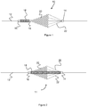
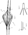
- Figures 1-3 show various embodiments for the embolic protection device that each have an expanded configuration for trapping embolic particles and a contracted configuration which it adopts when being delivered through a delivery device 30 (i.e., microcatheter) as shown in Figure 4-6 .
- the embolic protection devices 10, 11, and 13 sit over a delivery wire 12 and include a filter 20 used to capture thrombus.
- the filter 20 is a braid or mesh formed from one or more wires (e.g., wires composed of Nitinol, stainless steel, cobalt chromium, and/or a polymer material). Radiopaque material (i.e. tantalum or platinum) could also be used in the constituent wires comprising the mesh.
- This mesh or braided filter 20 can be formed from a single mesh/braid layer or from multiple layers (e.g., a larger porosity layer and a smaller porosity layer).
- the filter is formed from a single solid material (e.g., a laser-cut tube).
- Each of the devices 10, 11, and 13 include one or more struts 22 connected to various locations on the filter 20, to assist in expanding and contracting the filter 20 during a procedure. Since the struts 22 are oriented proximally or closest to the delivery device 30, they act to close the filter 20 as each of the devices 10, 11, and 13 are retracted within the delivery device 30.
- the struts 22 and filter 20 are each able to expand over the deliver wire 12 via a fixed joint 14 and a sliding joint 16.
- the struts 22 are connected to the fixed joint 14, which is stationary relative to the delivery wire 12.
- the sliding joint 16 is connected to a distal end of the filter 20, allowing it to slide relative to the deliver wire 12 as the device expands and contracts.
- the filter 20 forms a generally conical shape that functions to capture thrombus emanating from a more proximal portion of the vessel. Therefore the open (enlarged) portion of filter 20 is proximal relative to the portion of the filter connected to the sliding joint 16, and struts 22 are proximal relative to filter 20.
- the devices 10, 11, and 13 can also include a compression member 18 that can assist or bias the device into an expanded position.
- the compression member 18 is disposed over the delivery wire 12 and is connected to sliding joint 16 and a fixed joint 15, all located distally of the filter 20.
- the compression member 18 can include a metal or plastic spring-like member, a solid resilient polymer member, an elastic material, or materials with a similar behavior/functionality.
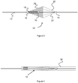
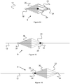
- Figure 4 shows the compressed configuration of the embolic protection device 10 when positioned in a delivery device 30 (i.e. a microcatheter).
- a delivery device 30 i.e. a microcatheter.
- the filter 20 and struts 22 exert a force on sliding joint 16.
- Sliding joint 16 moves distally toward the fixed joint 15 resulting in compression of the compression member 18.
- the compression member 18 moves from a compressed to expanded configuration, proximally pushing the filter 20 and struts 22 to an open or expanded configuration.
- the filter 20 and/or struts 22 may be composed of shape-memory materials that are biased or "heat-set" to an expanded configuration, these components may further exert expansile force after deployment from the delivery device 30.
- the fixed joint 15 anchors the compression member 18, which in turn helps to create a backstop for over-expansion of the filter 20.
- FIG. 5 shows the compressed configuration of the embolic protection device 11 of Figure 2 when positioned in a delivery device 30 (i.e. a microcatheter).
- a delivery device 30 i.e. a microcatheter.
- the filter 20 and compression member 18 exert force on sliding joint 16, causing the sliding joint 16 to slide in a distal direction, stretching out the compression member.
- compression member 18 will exert an unrestrained pulling force between joints 14 and 16, causing the filter 20 to expand, and maintain its expanded shape.
- the filter 20 and/or struts 22 may be composed of shape-memory materials that are biased or "heat-set" to an expanded configuration, these components may further exert expansile force after deployment from the delivery device 30.
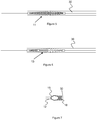
- the compression member 18 is coupled between sliding joint 16 and distal fixed joint 15 (distal fixed joint 15 is distal relative to fixed joint 14). In contrast to the device 10 embodiment shown in Figure 1 , the compression member 18 is located within the filter 20. In contrast to the device 11 embodiment shown in Figure 2 , the compression member 18 only expands partially between the sliding joint 16 and fixed joint 14.
- Figure 6 shows the compressed configuration of the embolic protection device 13 of Figure 3 .
- the compression member 18 contracts, pulling the sliding joint 16 proximally towards the fixed joint 15.
- the filter 20 and/or struts 22 may be composed of shape-memory materials that are biased or "heat-set" to an expanded configuration, these components may further exert expansile force after deployment from the delivery device 30.
- Figure 7 shows an embodiment of the configuration of distal fixed joint 15 from Figure 1 .
- the distal fixed joint 15 has a tapered shape between delivery wire 12 and compression member 18.
- the fixed joint 15 preferably has a smooth profile and no sharp edges to help reduce blood vessel trauma as the embolic protection device 10 is tracked through the vasculature.
- the profile of the device is such that it operatively mates with the distal end of delivery device 30.
- the distal fixed joint 15 sits just distal to delivery device 30 and mates with the distal opening of said delivery device 30.
- the shape described for the distal fixed joint in Figure 7 can be used on sliding joint 16 of device 11 and 13 in Figures 2 and 3 , respectively. In this way, the distal-most joint would effectively function as a 'seal' for the rest of the device as its sits in the delivery device 30.
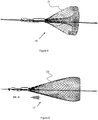
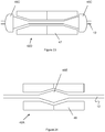
- the device 15 includes a filter 21 that is inverted from outside-in, creating a flared outer layer and a reduced inner layer.
- the filter 21 is pulled inward from a single layer to create the second, underlying layer.
- a smaller diameter tube is placed internally within the mesh or braid which forms the filter 20. A portion of the mesh or braid is then pulled through this smaller diameter tube in order to create the smaller diameter region of the filter.
- the filter 20 can be heat seat into this final shape, the free ends of the filter may be inserted into a common element (i.e. sliding joint 16), or both techniques can be used.
- the filter 21 is created by placing a larger diameter tube over the external diameter of the mesh or braid, and then pulling it loosely over said tube to create the larger flared region.
- the filter 23 of device 17 is inverted from inside-out, forming an inner layer and outer layer.
- the filter 23 is pulled and folded outward, over itself to produce the outer, second layer.
- the outer layer can be pulled taut to achieve the lengthier profile shown in Figure 9 or left loose to achieve a profile similar to the one shown in Figure 8 .
- a larger diameter tube is placed external to the mesh or braid which forms the filter. A portion of the mesh or braid is moved over and around the external diameter of the tube to create the second, overlapping region.
- the filter can be heat seat into this final shape, the free ends of the filter may be inserted into a common element (i.e. sliding joint 16), or both techniques can be used.
- the filter 23 could be created by placing a smaller diameter tube under the mesh or braid, and then pulling the mesh or braid tautly under said tube to create the underlying region.
- struts 22 that are connected to and support the filter 20.
- the struts 22 can help control the expansion of filter 20 by providing a controlled restraining force. Since the struts 22, in some embodiments, are connected to fixed joint 14, they help the filter 20 collapse when re-inserting the filter 20 into the delivery device 30. During reinsertion, the struts 22 will provide a restraining force on the filter 20, in combination with the action of the sliding joint 16 and compression member 18. Thus the struts 22 help control the filter 20 expansion, and aid in filter 20 collapse during insertion into the delivery device 30.
- the struts 22 can be constructed in a number of configurations.
- metallic struts 22 can be used with the dual layer filter 23 shown in Figure 9 .
- the struts 22 connect to both layers of the inverted or everted mesh to provide a stronger anchor point for the connection.
- the struts 22 may include a connecting member 24 (e.g., a hook shape or loop) to connect to the filter 23.
- the connecting member 24 may be heat set to form a shape that connects to the filter 23 or may be directly treated to bond to the filter 23.
- the connecting member 24 is a coil that encompasses the end of the strut 22 and forms a loop through a pore of the filter 23.
- This coil helps secure the strut 22 against the filter 23 and provides a surface which is both softer and has a higher surface area to push against the filter.
- a number of materials can be used for the struts 22, including Nitinol, stainless steel, polymer, radiopaque materials (i.e. tantalum, platinum, or palladium) and combinations therein.
- the struts 22 are each single wires which extend through pores on the filter 23 and connect back to themselves, forming an end loop.
- the end of the wires can be fixed to themselves via a connecting component such as a crimped sleeve or can be bonded to each other with an adhesive, welding, similar technique.
- the one or more struts 22 have a curved region 26 adapted to mate with a corresponding curved region of the filter 20.
- This curved region 26 can extend from a single strut 22 or between two struts 22 and can further be welded or heat treated to fix to the corresponding curved region of filter 20. This design allows the force created by retracting into the delivery device 30 to spread over a larger area of the filter 20.
- the struts 22 are constructed from a tube (e.g., a laser-cut Nitinol tube) with a tubular end on one end, and a plurality of fingers on the other end. These fingers act as the strut 22 and are connected to the edges of the filter 22.
- the tubular region opposite the fingers may be crimped or fixed to the delivery wire 12, thereby acting as a fixed joint.
- Figure 14 shows another embodiment of an embolic protection device 9 that includes a sliding joint 34 at the proximal end of the device 9 and a second sliding joint 32 at the distal end of the device 9.
- a stop 28 is located between the two stops 32 and 34 which limits the proximal and distal translation of the device 9.
- the device's distal translation is limited by stop 28 interacting with proximal slider 34 (seen in Figure 15 )
- the device's proximal translation is limited by stop 28 interacting with distal slider 32 (seen in Figure 16 ).
- the sliding joints 32, 34 are disposed or captured around the delivery wire 12 but cause minimal friction with the wire, thus allowing the joints 32, 34 to easily slide.
- FIGS 17-18 show an embodiment of a rapid exchange catheter 31 used for delivery of an embolic protection device 10 (or any of the devices described in this specification).
- Catheter 31 includes a distal port 36 used as an access port for a guidewire 40, which, when inserted, is used to track or direct delivery of catheter 31 to a certain target region within the vasculature.
- Proximal port 38 is used as an access port for the embolic protection device 10, allowing the device 10 to reach the desired target location achieved by the guidewire 40.
- the diameter of guidewire 40 and delivery wire 12 can both be about .014".
- Various diameters could also be used, lesser or greater, and this value is only offered as an example.
- Another aspect of the present invention can allow one or more of the proximal joints 44 and/or distal joints 42 to be rotatable, as seen in Figures 20-24 .
- the distal joint 42 is rotatable to allow rotation of the filter 20 in the vasculature as it expands and retracts. This allows the device 10 to better conform to the patient's vessel and reduce any unwanted stress that results in undesirable functionality of the device 10.
- Figure 20 illustrates one embodiment of a rotatable joint 42A, having two enlarged sections 46A that are fixed from translation and rotation to the delivery wire 12.
- the outer rotational member 42A may fit directly over the wire 12, thereby capturing the wire 12, while the enlarged sections 46A prevent translational movement of the region 42A. Hence, the outer rotational member 42A (and anything attached to it) can rotate in place.
- Figure 21 illustrates another embodiment of a joint 42B in which the outer rotational member 43 includes a recessed cavity that accommodates a fixed, enlarged member 46B.
- the fixed, enlarged member 46B is fixed to the wire 12 to prevent translational or rotational movement.
- the member 46B is also sized large enough such that it is unable to pass through the reduced diameter portions of the outer rotational member 43.
- the outer rotational member 43 effectively captures the member 46B, but can rotate in place.
- Figure 22 illustrates another embodiment of a joint 42C that is generally similar to joint 42A, however, one of the fixed, enlarged members 46B includes a tapered region while the outer rotational member 45 includes a reciprocal tapered region.
- Figure 23 illustrates another embodiment of a joint 42E in which both ends of the outer rotational member 47 have tapered regions that reciprocate with two fixed, enlarged members 46C.
- Figure 24 illustrates yet another embodiment of a joint 42E that is generally similar to joint 42B, but that the outer rotational member 49 includes a tapered, recessed area that captures a reciprocally tapered fixed, enlarged member 46E.
- the joints described may be comprised of a variety of materials including Nitinol, stainless steel, cobalt chromium, polymer, radiopaque material (i.e. platinum or tantalum) or various combinations therein. As previously discussed, these rotational joints can be used in any of the embodiments discussed in this specification. Additionally the enlarged members 46A-46E may be offset (or shrunk in respect to the cavity housing) to allow for some translational freedom, in addition to rotation.
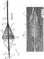
- Figure 25 illustrates another embodiment of an embolic protection device 50 that is generally similar to previously described embodiments, in that the device 50 includes an expandable, conical filter 64 having a proximal fixed joint 58 and a distal sliding joint 60. Unlike the previous embodiments, the filter 64 is disposed over a tube 56 (e.g., a polyimide tube) onto which both joints 58 and 60 are located and which allows passage for both the delivery wire 12 and guidewire 40.
- the device 50 functions as a "monorail" or rapid exchange type filter.
- delivery wire 12 sits within all or a portion of tube 56 (where tube 56 is placed over said delivery wire), in another example delivery wire 12 ends at the proximal end of tube 56.
- the filter 64 is preferably composed of a plurality of smaller diameter wires 52 woven with a plurality of larger diameter wires 54.
- the smaller diameter wires 52 may have a diameter in the range of about 0.0127 mm to 0.057 mm (0.0005 -0.00225 inch) while the larger diameter wires 54 may have a diameter in the range of about 0.057 mm - 0.2032 mm (0.00225 -0.008 inches).
- about 4 to 16 larger wires 54 can be used and about 72 to 288 smaller diameter wires 52 can be used.
- the larger diameter wires 54 can also form the struts on the proximal end of the device 50.
- the larger diameter wires 54 may have the same or similar diameter as wires 52, but may be composed of a stronger or stiffer material (e.g., cobalt chromium wires 54 and Nitinol wires 52).
- the filter 64 when in an expanded configuration, has a generally conical shape with a less porous end portion 64A (i.e., the region near the open end).
- this end portion 64A expands and reduces in diameter, following the general shape of the proximal larger wires 54. At least partial expansion of this end portion 64A can be seen in Figure 26 .
- the filter 64 cinches or closes around the proximal portion of any particles caught within the filter 64 prior to any substantial reduction in diameter of the remaining, distal portions of the filter 64.
- the proximal end of the filter 64 at least partially closes first, preventing the distal end of the filter 64 from squeezing out any of the particles into the patient's vessels.
- the end portion 64A can be created by heat setting this area to a more compressed configuration than the remaining portions, or can be formed from a varying or different weave pattern.
- end portion 64A may have a substantially constant diametric profile rather than the reduced profile shown.
- Figures 28-31 illustrate various example steps that can be used to create the device 50.
- a tubular stent-like structure 63 can be first woven or braided with the previously discussed wires 52 and 54.
- the center region 64A (also referred to as end portion 64A in the finished filter 64), is preferably heat set to a more compressed configuration than the remaining portions of the tube 63.
- a proximal end of the tube 63 is crimped on to tube 56 via fixed joint member 58 and a proximal end of the tube 63 is connected to sliding joint 60 to the tube 56.
- This arrangement creates a mesh structure with two conical ends 64B.
- a second distal, flexible tube 62 (see Figure 25 ) is fixed to the end of the tube 56 to provide the device 50 with an atraumatic tip.
- Flexible tube 62 may be polymeric (i.e. PTFE) or metallic, and can have a consistent or variable stiffness profile.
- variable stiffness profile would be useful to have a graduated stiffness along the length of the tube, where the distal most portion (likely to contact the vessel) will be more flexible.
- This variable stiffness profile can be achieved by using various polymers or metals along the length of the tube with different material profiles.
- a laser cut spiral pattern is utilized on the metallic or polymeric tube.
- a coil may be positioned under the tube, with the polymer heat set over the coil (i.e. heat shrunk tubing). This coil would provide additional flexibility to the flexible tube section.
- Flexible tube 62 contains a channel which the guidewire sits through to enable tracking through the vasculature.
- one or more radiopaque markers 53 can be fixed at various locations on the filter 64.
- markers 53 can be fixed to the larger wires 54 at locations near the end portion 64A or at the free edge of the filter 64 (i.e., near the electro-polished free ends of the wires 52).
- Figure 32 illustrates yet another embodiment of an embolic protection device 70 that is generally similar to the previously described embodiments, but further includes a generally parabolic shape of its filter 72.
- a generally parabolic shape of its filter 72 By providing a more rounded distal end 72A to the filter 72 instead of a more straight or linear decrease, the pore size of the filter's mesh can remain more consistent and therefore improve distal blood flow through it.
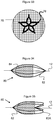
- Figure 33 illustrates a distal end view of a filter 76 having a plurality of struts or larger diameter wires that form a support basket 78 for the mesh of the filter 76.
- the basket 78 provides additional support and even assists in expansion/contraction of the filter 76.
- the wire of the basket 78 is composed of Nitinol and is heat set to a desired "open" or expanded configuration.
- the basket 78 can be located within the filter 76, woven within the filter's mesh, or located on and fixed to an outer side of the filter 76.
- Figures 34 and 35 illustrate another embodiment of an embolic protection device 80, having a plurality of elongated struts 82 that are fixed to a filter 84.
- the struts 82 can be heat-set to a configuration of either the football/elliptical shape of Figure 34 or the partially inverted shape of Figure 35 , and can both be compressed and deployed in those shapes.
- the struts 82 can be heat-set to have the expanded, partially-inverted shape of Figure 35 , but can be loaded into a delivery device 30 in the shape of Figure 34 , thereby self-inverting to the shape of Figure 35 after deployment.
- the struts can be formed by laser-cutting a Nitinol tube to create a "unibody" framework to help evenly distribute force along a vessel's wall.
- Figure 36 illustrates another embodiment of an embolic protection device 86 having a generally oval or elliptical shape.
- This device 86 can be created with a tubular, stent-like structure, having larger diameter wires 88 and smaller diameter wires 87 woven together.
- the proximal end can be crimped or connected via a fixed joint to a delivery wire 12, while the distal end can be connected via sliding joint to the delivery wire 12.
- the proximal-most portion of the devices of this specification can accommodate both a delivery wire 12 (which the device is disposed on) as well as a guidewire 40, which thereby acts as a monorail or rapid exchange catheter. It should be understood that several different configurations are possible to accommodate these wires 12, 40, examples of which are illustrated in Figures 37-44 .
- Figures 37-38 illustrate other configurations of rapid exchange catheter ports involving variations of Figures 17-18 .
- the port would comprise one large opening segmented into two parts, the more distal port (i.e. 96) would be used for the guidewire while the more proximal port (i.e. 98) would be used for the embolic protection device.
- one of the ports could be perforated (i.e. more distal port 90) to provide some tactile reference of which port is used for which purpose.
- Figures 39-40 illustrate various example cross-sectional configurations of a fixed joint or proximal-most portion of device embodiments with a rapid exchange capability.
- cross section 100 includes a first passage 102 and a second passage 104, where one of the passages may accommodate guidewire 40 and the other accommodates delivery wire 12.
- Figure 40 illustrates a cross section 106 having a first, round passage 108 for guidewire 40 and a second arc-shaped passage 110 for the delivery wire 12.
- the delivery wire 12 would also be generally arc-shaped so as to fit within the passage 110.
- the passage 110 is also preferably located relatively close to the passage 108 and has an inner arc shape that is somewhat larger than the diameter of the passage 108, reducing the overall diameter of the device.
- Figures 41-44 these embodiments disclose various example port and passage locations.
- a fixed joint 120 is illustrated, having a first port 120C and a second port 120B that both lead to the same internal passage 120A.
- the delivery wire 12 can pass directly through port 120C, while the guidewire can pass, somewhat skewed of center via port 40, while sharing the same passage 120A through the device.
- the fixed joint 122 includes only a single port 122B and single passage 122A through the device. Hence, delivery wire 12 and guidewire 40 can share both the port 122B and the passage 122A.
- the joint 124 includes a first passage 124A opening to port 124B, and a second passage 124C opening to port 124D.
- the guidewire 40 can travel through its own passage 124A and port 124B, while the delivery wire 12 can operate in passage 124C and passage 124D.
- Figure 44 illustrates a joint 122 with a single passage 122A and port 122B, similar to that shown in Figure 42 .
- the delivery wire 12 further comprises its own internal guidewire passage 12b that opens proximally at port 12B and near a distal end of the device.
- the port 12A is preferably located such that it is proximal of the joint 122 during normal operation.
- the guidewire 40 can pass into the device (e.g., through an atraumatic end) and into a distal end of the wire 12, into its passage 12B and finally out its port 12A.
- the passage 12B and port 12A are sized so as to accommodate a guidewire 40.
- the joint itself may include a port such as port 124B of Figure 43 , and this port leads into a port within the delivery wire which the guidewire can be inserted through.
- Proximal joint 58 and distal joint 60 may have different configurations as well aside from the fixed proximal, translatable distal examples discussed earlier.
- proximal joint 58 may have some translational capability (via one or more stops placed in proximity to said proximal joint) and/or some rotational capability via the joint not being complete fixed to tube 56.
- Distal joint 60 may have more limited translational capability via the inclusion of one or more stops placed in the proximity of the joint, and/or some rotational capability via the joint not being completely fixed to tube 56.
- a delivery device such as a microcatheter
- a delivery device 130 allows the distal end of the delivery device to open or expand, thereby creating a somewhat tapered distal end to facilitate gentle deployment and retraction of the various embolic protection devices of this specification.
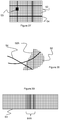
- a cut or slit 136 in a delivery device 130 can be created just prior to deployment of an embolic protection device.
- An opening device 134 shaped to cut or rip the wall of the delivery device 130, can be located at or near the very distal end of the device 130.
- a wire 132 is connected to the opening device 134 and extends to a proximal end of the device 130, allowing the physician to pull the opening device 134, creating a cut.
- the wire 132 is located within its own passage within the delivery device 130.
- a perforation is located along the wall of the delivery device 130 to assist in the creation of the cut.
- the distal end of the delivery device 130 includes a "C" shaped metal component that is biased to outwardly expand subsequent to creation of the cut 136.
Landscapes
- Health & Medical Sciences (AREA)
- Cardiology (AREA)
- Oral & Maxillofacial Surgery (AREA)
- Transplantation (AREA)
- Engineering & Computer Science (AREA)
- Biomedical Technology (AREA)
- Heart & Thoracic Surgery (AREA)
- Vascular Medicine (AREA)
- Life Sciences & Earth Sciences (AREA)
- Animal Behavior & Ethology (AREA)
- General Health & Medical Sciences (AREA)
- Public Health (AREA)
- Veterinary Medicine (AREA)
- Surgical Instruments (AREA)
Applications Claiming Priority (2)
| Application Number | Priority Date | Filing Date | Title |
|---|---|---|---|
| US201361799114P | 2013-03-15 | 2013-03-15 | |
| PCT/US2014/030738 WO2014145892A2 (en) | 2013-03-15 | 2014-03-17 | Embolic protection device |
Publications (3)
| Publication Number | Publication Date |
|---|---|
| EP2967806A2 EP2967806A2 (en) | 2016-01-20 |
| EP2967806A4 EP2967806A4 (en) | 2016-10-05 |
| EP2967806B1 true EP2967806B1 (en) | 2017-12-06 |
Family
ID=51538560
Family Applications (1)
| Application Number | Title | Priority Date | Filing Date |
|---|---|---|---|
| EP14765066.7A Active EP2967806B1 (en) | 2013-03-15 | 2014-03-17 | Embolic protection device |
Country Status (9)
| Country | Link |
|---|---|
| US (2) | US9693852B2 (enExample) |
| EP (1) | EP2967806B1 (enExample) |
| JP (3) | JP6636908B2 (enExample) |
| KR (3) | KR102698809B1 (enExample) |
| CN (1) | CN105377184B (enExample) |
| AU (1) | AU2014232401B2 (enExample) |
| BR (1) | BR112015023602A2 (enExample) |
| CA (1) | CA2906189A1 (enExample) |
| WO (1) | WO2014145892A2 (enExample) |
Families Citing this family (210)
| Publication number | Priority date | Publication date | Assignee | Title |
|---|---|---|---|---|
| CA2625826C (en) | 2005-10-19 | 2014-08-05 | Pulsar Vascular, Inc. | Methods and systems for endovascularly clipping and repairing lumen and tissue defects |
| US9402707B2 (en) | 2008-07-22 | 2016-08-02 | Neuravi Limited | Clot capture systems and associated methods |
| JP5791048B2 (ja) | 2008-09-05 | 2015-10-07 | パルサー バスキュラー インコーポレイテッド | 生理的開口部又は腔を支持し又は閉塞するシステム及び方法 |
| US9463036B2 (en) | 2010-10-22 | 2016-10-11 | Neuravi Limited | Clot engagement and removal system |
| US11259824B2 (en) | 2011-03-09 | 2022-03-01 | Neuravi Limited | Clot retrieval device for removing occlusive clot from a blood vessel |
| US12076037B2 (en) | 2011-03-09 | 2024-09-03 | Neuravi Limited | Systems and methods to restore perfusion to a vessel |
| ES3029850T3 (en) | 2011-03-09 | 2025-06-25 | Neuravi Ltd | A clot retrieval device for removing occlusive clot from a blood vessel |
| JP6219270B2 (ja) | 2011-06-03 | 2017-10-25 | パルサー バスキュラー インコーポレイテッド | 動脈瘤装置 |
| US10779855B2 (en) | 2011-08-05 | 2020-09-22 | Route 92 Medical, Inc. | Methods and systems for treatment of acute ischemic stroke |
| EP3735916A1 (en) | 2011-10-05 | 2020-11-11 | Pulsar Vascular, Inc. | Devices for enclosing an anatomical opening |
| US10561509B2 (en) | 2013-03-13 | 2020-02-18 | DePuy Synthes Products, Inc. | Braided stent with expansion ring and method of delivery |
| US10603157B2 (en) | 2013-03-13 | 2020-03-31 | DePuy Synthes Products, Inc. | Braid implant delivery and retraction device with distal engagement |
| JP2016513505A (ja) | 2013-03-14 | 2016-05-16 | ニューラヴィ・リミテッド | 血管から閉塞血餅を除去するための血餅回収デバイス |
| SI2967611T1 (sl) | 2013-03-14 | 2019-04-30 | Neuravi Limited | Naprava za odstranjevanje akutnih blokad iz krvnih žil |
| US9433429B2 (en) | 2013-03-14 | 2016-09-06 | Neuravi Limited | Clot retrieval devices |
| US9265512B2 (en) | 2013-12-23 | 2016-02-23 | Silk Road Medical, Inc. | Transcarotid neurovascular catheter |
| US10285720B2 (en) | 2014-03-11 | 2019-05-14 | Neuravi Limited | Clot retrieval system for removing occlusive clot from a blood vessel |
| US11076860B2 (en) | 2014-03-31 | 2021-08-03 | DePuy Synthes Products, Inc. | Aneurysm occlusion device |
| US11154302B2 (en) | 2014-03-31 | 2021-10-26 | DePuy Synthes Products, Inc. | Aneurysm occlusion device |
| WO2015189354A1 (en) | 2014-06-13 | 2015-12-17 | Neuravi Limited | Devices for removal of acute blockages from blood vessels |
| US10265086B2 (en) | 2014-06-30 | 2019-04-23 | Neuravi Limited | System for removing a clot from a blood vessel |
| US9918718B2 (en) | 2014-08-08 | 2018-03-20 | DePuy Synthes Products, Inc. | Embolic coil delivery system with retractable mechanical release mechanism |
| US10206796B2 (en) | 2014-08-27 | 2019-02-19 | DePuy Synthes Products, Inc. | Multi-strand implant with enhanced radiopacity |
| US9782178B2 (en) | 2014-09-19 | 2017-10-10 | DePuy Synthes Products, Inc. | Vasculature occlusion device detachment system with tapered corewire and heater activated fiber detachment |
| EP3682821B1 (en) | 2014-11-26 | 2022-05-11 | Neuravi Limited | A clot retrieval device for removing an occlusive clot from a blood vessel |
| US10617435B2 (en) | 2014-11-26 | 2020-04-14 | Neuravi Limited | Clot retrieval device for removing clot from a blood vessel |
| US11253278B2 (en) | 2014-11-26 | 2022-02-22 | Neuravi Limited | Clot retrieval system for removing occlusive clot from a blood vessel |
| US10736730B2 (en) | 2015-01-20 | 2020-08-11 | Neurogami Medical, Inc. | Vascular implant |
| US11484319B2 (en) | 2015-01-20 | 2022-11-01 | Neurogami Medical, Inc. | Delivery system for micrograft for treating intracranial aneurysms |
| US10857012B2 (en) | 2015-01-20 | 2020-12-08 | Neurogami Medical, Inc. | Vascular implant |
| US10925611B2 (en) | 2015-01-20 | 2021-02-23 | Neurogami Medical, Inc. | Packaging for surgical implant |
| CA2972620C (en) | 2015-01-20 | 2023-08-01 | Neurogami Medical, Inc. | Micrograft for the treatment of intracranial aneurysms and method for use |
| DE202016009165U1 (de) | 2015-02-04 | 2023-04-26 | Route 92 Medical, Inc. | System für schnelle Aspirationsthrombektomie |
| US10799669B2 (en) | 2017-01-20 | 2020-10-13 | Route 92 Medical, Inc. | Single operator intracranial medical device delivery systems and methods of use |
| US10426497B2 (en) | 2015-07-24 | 2019-10-01 | Route 92 Medical, Inc. | Anchoring delivery system and methods |
| US11065019B1 (en) | 2015-02-04 | 2021-07-20 | Route 92 Medical, Inc. | Aspiration catheter systems and methods of use |
| BR102015011376B1 (pt) | 2015-05-18 | 2023-04-04 | Murilo Pundek Rocha | Brônquio artificial implantável |
| EP3141212B1 (en) * | 2015-09-10 | 2019-11-06 | Endovascular Development AB | An extendable, retrievable endovascular element |
| US10314593B2 (en) * | 2015-09-23 | 2019-06-11 | Covidien Lp | Occlusive devices |
| KR102571962B1 (ko) | 2015-10-31 | 2023-08-28 | 뉴로바스크 테크놀로지스, 아이엔씨. | 혈액 흐름 제한을 갖는 색전 제거 장치 및 관련 방법 |
| JP7012655B2 (ja) | 2016-02-24 | 2022-01-28 | インセプト、リミテッド、ライアビリティ、カンパニー | 可撓性の強化された神経血管カテーテル |
| CN107174373B (zh) * | 2016-03-09 | 2019-03-12 | 微创心脉医疗科技(上海)有限公司 | 滤器装置 |
| CN109069254B (zh) * | 2016-05-06 | 2020-07-31 | 心脏器械股份有限公司 | 具有局部溶栓药物输送的血液凝块过滤器 |
| US10898203B2 (en) | 2016-05-18 | 2021-01-26 | Microvention, Inc. | Embolic containment |
| US10555738B2 (en) | 2016-05-18 | 2020-02-11 | Microvention, Inc. | Embolic containment |
| US10285710B2 (en) | 2016-06-01 | 2019-05-14 | DePuy Synthes Products, Inc. | Endovascular detachment system with flexible distal end and heater activated detachment |
| US10420563B2 (en) * | 2016-07-08 | 2019-09-24 | Neurogami Medical, Inc. | Delivery system insertable through body lumen |
| CN109862835B (zh) | 2016-08-17 | 2022-09-13 | 尼尔拉维有限公司 | 用于从血管中移除闭塞凝块的凝块收回系统 |
| US10076428B2 (en) | 2016-08-25 | 2018-09-18 | DePuy Synthes Products, Inc. | Expansion ring for a braided stent |
| EP3854322B1 (en) | 2016-09-06 | 2024-01-17 | Neuravi Limited | A clot retrieval device for removing occlusive clot from a blood vessel |
| US10292851B2 (en) | 2016-09-30 | 2019-05-21 | DePuy Synthes Products, Inc. | Self-expanding device delivery apparatus with dual function bump |
| US10517708B2 (en) | 2016-10-26 | 2019-12-31 | DePuy Synthes Products, Inc. | Multi-basket clot capturing device |
| US10709466B2 (en) | 2016-11-23 | 2020-07-14 | Microvention, Inc. | Obstruction removal system |
| CN110381855B (zh) | 2017-01-06 | 2023-07-04 | 因赛普特有限责任公司 | 用于动脉瘤治疗装置的抗血栓涂层 |
| CN114984407B (zh) | 2017-01-10 | 2025-05-23 | 92号医疗公司 | 在颅内血管中执行医疗手术的系统、导管和导管前进装置 |
| US10905853B2 (en) | 2017-01-17 | 2021-02-02 | DePuy Synthes Products, Inc. | System and method for delivering a catheter |
| WO2018136584A1 (en) * | 2017-01-18 | 2018-07-26 | Boston Scientific Scimed, Inc. | Embolic protection device |
| ES2994282T3 (en) | 2017-01-20 | 2025-01-21 | Gore & Ass | Embolic filter system |
| US10881497B2 (en) | 2017-01-26 | 2021-01-05 | DePuy Synthes Products, Inc. | Composite vascular flow diverter |
| CN110545739A (zh) | 2017-02-23 | 2019-12-06 | 德普伊新特斯产品公司 | 动脉瘤装置及递送系统 |
| WO2019118374A1 (en) | 2017-12-12 | 2019-06-20 | Penumbra, Inc. | Vascular cages and methods of making and using the same |
| US10806462B2 (en) | 2017-12-21 | 2020-10-20 | DePuy Synthes Products, Inc. | Implantable medical device detachment system with split tube and cylindrical coupling |
| US10751065B2 (en) | 2017-12-22 | 2020-08-25 | DePuy Synthes Products, Inc. | Aneurysm device and delivery system |
| US10905430B2 (en) | 2018-01-24 | 2021-02-02 | DePuy Synthes Products, Inc. | Aneurysm device and delivery system |
| US11284902B2 (en) | 2018-02-01 | 2022-03-29 | Boston Scientific Scimed, Inc. | Method of making a vascular occlusion device |
| US11684465B2 (en) | 2018-03-27 | 2023-06-27 | Maduro Discovery, Llc | Accessory device to provide neuroprotection during interventional procedures |
| US10918390B2 (en) | 2018-03-30 | 2021-02-16 | DePuy Synthes Products, Inc. | Helical balloon assist device and method for using the same |
| US10786259B2 (en) | 2018-03-30 | 2020-09-29 | DePuy Synthes Products, Inc. | Split balloon assist device and method for using the same |
| US10806461B2 (en) | 2018-04-27 | 2020-10-20 | DePuy Synthes Products, Inc. | Implantable medical device detachment system with split tube |
| US11395665B2 (en) | 2018-05-01 | 2022-07-26 | Incept, Llc | Devices and methods for removing obstructive material, from an intravascular site |
| CN112203593B (zh) | 2018-05-01 | 2024-11-22 | 因赛普特有限责任公司 | 用于从血管内部位去除闭塞性物质的装置和方法 |
| EP4527441A3 (en) | 2018-05-17 | 2025-06-18 | Route 92 Medical, Inc. | Aspiration catheter systems and methods of use |
| US11058430B2 (en) | 2018-05-25 | 2021-07-13 | DePuy Synthes Products, Inc. | Aneurysm device and delivery system |
| US11596412B2 (en) | 2018-05-25 | 2023-03-07 | DePuy Synthes Products, Inc. | Aneurysm device and delivery system |
| US10939915B2 (en) | 2018-05-31 | 2021-03-09 | DePuy Synthes Products, Inc. | Aneurysm device and delivery system |
| US10667833B2 (en) | 2018-06-08 | 2020-06-02 | Neuravi Limited | Guidewire with an atraumatic clot-circumventing configured distal end for use in an endovascular medical system |
| US10898216B2 (en) | 2018-06-13 | 2021-01-26 | DePuy Synthes Products, Inc. | Vasculature obstruction capture device |
| US11471582B2 (en) | 2018-07-06 | 2022-10-18 | Incept, Llc | Vacuum transfer tool for extendable catheter |
| US11517335B2 (en) | 2018-07-06 | 2022-12-06 | Incept, Llc | Sealed neurovascular extendable catheter |
| AU2019204522A1 (en) | 2018-07-30 | 2020-02-13 | DePuy Synthes Products, Inc. | Systems and methods of manufacturing and using an expansion ring |
| US10905431B2 (en) | 2018-08-03 | 2021-02-02 | DePuy Synthes Products, Inc. | Spiral delivery system for embolic braid |
| US10278848B1 (en) | 2018-08-06 | 2019-05-07 | DePuy Synthes Products, Inc. | Stent delivery with expansion assisting delivery wire |
| US10456280B1 (en) | 2018-08-06 | 2019-10-29 | DePuy Synthes Products, Inc. | Systems and methods of using a braided implant |
| US10813780B2 (en) | 2018-08-08 | 2020-10-27 | DePuy Synthes Products, Inc. | Intraluminal implant delivery system and method |
| US11051825B2 (en) | 2018-08-08 | 2021-07-06 | DePuy Synthes Products, Inc. | Delivery system for embolic braid |
| US11351023B2 (en) | 2018-08-21 | 2022-06-07 | Claret Medical, Inc. | Systems and methods for protecting the cerebral vasculature |
| US10842498B2 (en) | 2018-09-13 | 2020-11-24 | Neuravi Limited | Systems and methods of restoring perfusion to a vessel |
| BR102019019522A2 (pt) | 2018-09-20 | 2020-04-07 | Depuy Synthes Products Inc | stent com fios conformados |
| US11123077B2 (en) | 2018-09-25 | 2021-09-21 | DePuy Synthes Products, Inc. | Intrasaccular device positioning and deployment system |
| JP7437312B2 (ja) * | 2018-09-28 | 2024-02-22 | テルモ株式会社 | フィルターデバイス |
| US11406416B2 (en) | 2018-10-02 | 2022-08-09 | Neuravi Limited | Joint assembly for vasculature obstruction capture device |
| US11253287B2 (en) | 2018-10-04 | 2022-02-22 | Neuravi Limited | Retrograde blood flow occlusion flushing device |
| US12285182B2 (en) | 2018-10-10 | 2025-04-29 | Innova Vascular, Inc. | Devices and methods for removing an embolus |
| US20230131648A1 (en) * | 2018-10-10 | 2023-04-27 | Innova Vascular, Inc. | Torqueable devices and methods for removing an embolus |
| US11076861B2 (en) | 2018-10-12 | 2021-08-03 | DePuy Synthes Products, Inc. | Folded aneurysm treatment device and delivery method |
| BR112021008489A2 (pt) * | 2018-11-19 | 2021-08-03 | Pulmair Medical, Inc. | brônquio artificial implantável, e, métodos para promover desinsuflação pulmonar e para entregar brônquio artificial implantável em uma passagem de ar . |
| CN111265277B (zh) * | 2018-12-05 | 2021-06-29 | 先健科技(深圳)有限公司 | 取栓装置 |
| US11147562B2 (en) | 2018-12-12 | 2021-10-19 | DePuy Synthes Products, Inc. | Systems and methods for embolic implant detachment |
| US11406392B2 (en) | 2018-12-12 | 2022-08-09 | DePuy Synthes Products, Inc. | Aneurysm occluding device for use with coagulating agents |
| US11272939B2 (en) | 2018-12-18 | 2022-03-15 | DePuy Synthes Products, Inc. | Intrasaccular flow diverter for treating cerebral aneurysms |
| US11039944B2 (en) | 2018-12-27 | 2021-06-22 | DePuy Synthes Products, Inc. | Braided stent system with one or more expansion rings |
| US11134953B2 (en) | 2019-02-06 | 2021-10-05 | DePuy Synthes Products, Inc. | Adhesive cover occluding device for aneurysm treatment |
| US11273285B2 (en) | 2019-02-07 | 2022-03-15 | DePuy Synthes Products, Inc. | Ancillary device for detaching implants |
| ES2974673T3 (es) | 2019-03-04 | 2024-07-01 | Neuravi Ltd | Catéter de recuperación de coágulos accionado |
| US11382633B2 (en) | 2019-03-06 | 2022-07-12 | DePuy Synthes Products, Inc. | Strut flow diverter for cerebral aneurysms and methods for preventing strut entanglement |
| US11337706B2 (en) | 2019-03-27 | 2022-05-24 | DePuy Synthes Products, Inc. | Aneurysm treatment device |
| US11185334B2 (en) | 2019-03-28 | 2021-11-30 | DePuy Synthes Products, Inc. | Single lumen reduced profile occlusion balloon catheter |
| US11766539B2 (en) | 2019-03-29 | 2023-09-26 | Incept, Llc | Enhanced flexibility neurovascular catheter |
| US11051928B2 (en) | 2019-04-11 | 2021-07-06 | Neuravi Limited | Floating carotid filter |
| US11931522B2 (en) | 2019-05-09 | 2024-03-19 | Neuravi Limited | Inflation lumen kink protection and balloon profile |
| US11607531B2 (en) | 2019-05-09 | 2023-03-21 | Neuravi Limited | Balloon catheter with venting of residual air in a proximal direction |
| US11571553B2 (en) | 2019-05-09 | 2023-02-07 | Neuravi Limited | Balloon guide catheter with thermally expandable material |
| US11957855B2 (en) | 2019-05-09 | 2024-04-16 | Neuravi Limited | Balloon guide catheter with positive venting of residual air |
| USD959659S1 (en) | 2019-05-10 | 2022-08-02 | DePuy Synthes Products, Inc. | Implant release handle |
| US11278292B2 (en) | 2019-05-21 | 2022-03-22 | DePuy Synthes Products, Inc. | Inverting braided aneurysm treatment system and method |
| US11602350B2 (en) | 2019-12-05 | 2023-03-14 | DePuy Synthes Products, Inc. | Intrasaccular inverting braid with highly flexible fill material |
| US10653425B1 (en) | 2019-05-21 | 2020-05-19 | DePuy Synthes Products, Inc. | Layered braided aneurysm treatment device |
| US12446886B2 (en) | 2019-05-21 | 2025-10-21 | DePuy Synthes Products, Inc. | Semispherical braided aneurysm treatment system and method |
| US11607226B2 (en) | 2019-05-21 | 2023-03-21 | DePuy Synthes Products, Inc. | Layered braided aneurysm treatment device with corrugations |
| US11672542B2 (en) | 2019-05-21 | 2023-06-13 | DePuy Synthes Products, Inc. | Aneurysm treatment with pushable ball segment |
| US11497504B2 (en) | 2019-05-21 | 2022-11-15 | DePuy Synthes Products, Inc. | Aneurysm treatment with pushable implanted braid |
| US11413046B2 (en) | 2019-05-21 | 2022-08-16 | DePuy Synthes Products, Inc. | Layered braided aneurysm treatment device |
| US11406403B2 (en) | 2019-06-14 | 2022-08-09 | Neuravi Limited | Visibility of mechanical thrombectomy device during diagnostic imaging |
| US11109939B2 (en) | 2019-06-14 | 2021-09-07 | DePuy Synthes Products, Inc. | Intravascular devices with radiopaque body markers |
| IL312949A (en) | 2019-06-15 | 2024-07-01 | Maduro Discovery Llc | Catheter construction |
| US11253265B2 (en) | 2019-06-18 | 2022-02-22 | DePuy Synthes Products, Inc. | Pull wire detachment for intravascular devices |
| US11207494B2 (en) | 2019-07-03 | 2021-12-28 | DePuy Synthes Products, Inc. | Medical device delivery member with flexible stretch resistant distal portion |
| US11426174B2 (en) | 2019-10-03 | 2022-08-30 | DePuy Synthes Products, Inc. | Medical device delivery member with flexible stretch resistant mechanical release |
| US11266426B2 (en) | 2019-07-10 | 2022-03-08 | DePuy Synthes Products, Inc. | Streamlined treatment of clot removal, angioplasty and prevention of restenosis using a single integrated intravascular device |
| US11266427B2 (en) | 2019-07-10 | 2022-03-08 | Neuravi Limited | Self-expanding intravascular medical device |
| US11395675B2 (en) | 2019-07-11 | 2022-07-26 | DePuy Synthes Products, Inc. | Clot retriever cleaning for reinsertion |
| EP4427686A3 (en) | 2019-09-11 | 2024-11-06 | Neuravi Limited | Expandable mouth catheter |
| US11439403B2 (en) | 2019-09-17 | 2022-09-13 | DePuy Synthes Products, Inc. | Embolic coil proximal connecting element and stretch resistant fiber |
| US12376859B2 (en) | 2019-09-17 | 2025-08-05 | DePuy Synthes Products, Inc. | Embolic coil proximal connecting element and stretch resistant fiber |
| WO2021076642A1 (en) | 2019-10-15 | 2021-04-22 | Imperative Care, Inc. | Systems and methods for multivariate stroke detection |
| EP4048169B1 (en) * | 2019-10-24 | 2025-01-08 | Virender K. Sharma | Left atrial appendage closure device |
| US11712231B2 (en) | 2019-10-29 | 2023-08-01 | Neuravi Limited | Proximal locking assembly design for dual stent mechanical thrombectomy device |
| US20210128183A1 (en) | 2019-10-31 | 2021-05-06 | Neuravi Limited | Thrombectomy and stenting system |
| US11376013B2 (en) | 2019-11-18 | 2022-07-05 | DePuy Synthes Products, Inc. | Implant delivery system with braid cup formation |
| USD902407S1 (en) * | 2019-11-19 | 2020-11-17 | Pulmair Medical, Inc. | Implantable artificial bronchus |
| US11628282B2 (en) | 2019-11-25 | 2023-04-18 | Neuravi Limited | No preparation balloon guide catheter |
| US11779364B2 (en) | 2019-11-27 | 2023-10-10 | Neuravi Limited | Actuated expandable mouth thrombectomy catheter |
| US11839725B2 (en) | 2019-11-27 | 2023-12-12 | Neuravi Limited | Clot retrieval device with outer sheath and inner catheter |
| US11517340B2 (en) | 2019-12-03 | 2022-12-06 | Neuravi Limited | Stentriever devices for removing an occlusive clot from a vessel and methods thereof |
| US11259821B2 (en) | 2019-12-18 | 2022-03-01 | Imperative Care, Inc. | Aspiration system with accelerated response |
| CN113365687A (zh) | 2019-12-18 | 2021-09-07 | 因普瑞缇夫护理公司 | 治疗静脉血栓栓塞疾病的方法和系统 |
| US11457926B2 (en) | 2019-12-18 | 2022-10-04 | DePuy Synthes Products, Inc. | Implant having an intrasaccular section and intravascular section |
| US11553935B2 (en) | 2019-12-18 | 2023-01-17 | Imperative Care, Inc. | Sterile field clot capture module for use in thrombectomy system |
| CN111134784B (zh) * | 2020-01-22 | 2022-04-19 | 北京弘海微创科技有限公司 | 一种血栓切割器 |
| US11457922B2 (en) | 2020-01-22 | 2022-10-04 | DePuy Synthes Products, Inc. | Medical device delivery member with flexible stretch resistant distal portion |
| US11992241B2 (en) | 2020-01-31 | 2024-05-28 | DePuy Synthes Products, Inc. | System to assist delivery of a mechanical intravascular treatment device |
| US11957354B2 (en) | 2020-02-10 | 2024-04-16 | DePuy Synthes Products, Inc. | Aneurysm implant support device |
| US11432822B2 (en) | 2020-02-14 | 2022-09-06 | DePuy Synthes Products, Inc. | Intravascular implant deployment system |
| US11633198B2 (en) | 2020-03-05 | 2023-04-25 | Neuravi Limited | Catheter proximal joint |
| US11944327B2 (en) | 2020-03-05 | 2024-04-02 | Neuravi Limited | Expandable mouth aspirating clot retrieval catheter |
| CA3171899A1 (en) | 2020-03-10 | 2021-09-16 | Imperative Care, Inc. | Enhanced flexibility neurovascular catheter |
| EP4117586A4 (en) * | 2020-03-11 | 2024-04-10 | Ka Medical, LLC | BRAIDED MEDICAL DEVICE AND METHOD |
| US11883043B2 (en) | 2020-03-31 | 2024-01-30 | DePuy Synthes Products, Inc. | Catheter funnel extension |
| US11759217B2 (en) | 2020-04-07 | 2023-09-19 | Neuravi Limited | Catheter tubular support |
| US11717308B2 (en) | 2020-04-17 | 2023-08-08 | Neuravi Limited | Clot retrieval device for removing heterogeneous clots from a blood vessel |
| US11871946B2 (en) | 2020-04-17 | 2024-01-16 | Neuravi Limited | Clot retrieval device for removing clot from a blood vessel |
| US11730501B2 (en) | 2020-04-17 | 2023-08-22 | Neuravi Limited | Floating clot retrieval device for removing clots from a blood vessel |
| US11523831B2 (en) | 2020-04-30 | 2022-12-13 | DePuy Synthes Products, Inc. | Intrasaccular flow diverter |
| US11737771B2 (en) | 2020-06-18 | 2023-08-29 | Neuravi Limited | Dual channel thrombectomy device |
| US11937836B2 (en) | 2020-06-22 | 2024-03-26 | Neuravi Limited | Clot retrieval system with expandable clot engaging framework |
| US11439418B2 (en) | 2020-06-23 | 2022-09-13 | Neuravi Limited | Clot retrieval device for removing clot from a blood vessel |
| US11395669B2 (en) | 2020-06-23 | 2022-07-26 | Neuravi Limited | Clot retrieval device with flexible collapsible frame |
| US11951026B2 (en) | 2020-06-30 | 2024-04-09 | DePuy Synthes Products, Inc. | Implantable medical device detachment system with flexible braid section |
| US20220031341A1 (en) | 2020-07-29 | 2022-02-03 | Neuravi Limited | Adhesive-Free Bonded Balloon for a Balloon Guide Catheter With Minimal Outer Profile |
| US12447319B2 (en) | 2020-07-29 | 2025-10-21 | Neuravi Limited | Enhanced balloon bonding for balloon guide catheters while minimizing outer profiles |
| US11207497B1 (en) | 2020-08-11 | 2021-12-28 | Imperative Care, Inc. | Catheter with enhanced tensile strength |
| US11864781B2 (en) | 2020-09-23 | 2024-01-09 | Neuravi Limited | Rotating frame thrombectomy device |
| US20220111177A1 (en) | 2020-10-09 | 2022-04-14 | Route 92 Medical, Inc. | Aspiration catheter systems and methods of use |
| USD954953S1 (en) | 2020-11-03 | 2022-06-14 | Pulmair Medical, Inc. | Implantable artificial bronchus |
| US12440646B2 (en) | 2020-11-06 | 2025-10-14 | DePuy Synthes Products, Inc. | Catheter braid wire with variable cross-section shape |
| US11826520B2 (en) | 2020-12-08 | 2023-11-28 | DePuy Synthes Products, Inc. | Catheter designs for enhanced column strength |
| US11786698B2 (en) | 2020-12-08 | 2023-10-17 | DePuy Synthes Products, Inc. | Catheter with textured surface |
| US11937837B2 (en) | 2020-12-29 | 2024-03-26 | Neuravi Limited | Fibrin rich / soft clot mechanical thrombectomy device |
| US12029442B2 (en) | 2021-01-14 | 2024-07-09 | Neuravi Limited | Systems and methods for a dual elongated member clot retrieval apparatus |
| US11872354B2 (en) | 2021-02-24 | 2024-01-16 | Neuravi Limited | Flexible catheter shaft frame with seam |
| US12064130B2 (en) | 2021-03-18 | 2024-08-20 | Neuravi Limited | Vascular obstruction retrieval device having sliding cages pinch mechanism |
| US11974764B2 (en) | 2021-06-04 | 2024-05-07 | Neuravi Limited | Self-orienting rotating stentriever pinching cells |
| US11998213B2 (en) | 2021-07-14 | 2024-06-04 | DePuy Synthes Products, Inc. | Implant delivery with modified detachment feature and pull wire engagement |
| US20230052862A1 (en) | 2021-08-12 | 2023-02-16 | Imperative Care, Inc. | Sterile packaging assembly for robotic interventional device |
| US12369920B2 (en) | 2021-09-22 | 2025-07-29 | DePuy Synthes Products, Inc. | Introducer sheath having an intentional friction zone to hold in position a delivery system suitable for implantable intravascular devices |
| US11937839B2 (en) | 2021-09-28 | 2024-03-26 | Neuravi Limited | Catheter with electrically actuated expandable mouth |
| USD1077996S1 (en) | 2021-10-18 | 2025-06-03 | Imperative Care, Inc. | Inline fluid filter |
| US12011186B2 (en) | 2021-10-28 | 2024-06-18 | Neuravi Limited | Bevel tip expandable mouth catheter with reinforcing ring |
| US11624239B1 (en) | 2021-11-04 | 2023-04-11 | Halliburton Energy Services, Inc. | Pulse power drilling assembly transformer with a core having insulative and electrically conductive materials |
| US11873715B2 (en) | 2021-11-04 | 2024-01-16 | Halliburton Energy Services, Inc. | Pulse power drilling assembly transformer with a core having a non-conductive material |
| US11751881B2 (en) | 2021-11-26 | 2023-09-12 | DePuy Synthes Products, Inc. | Securement wire withstanding forces during deployment of implantable intravascular treatment device using a delivery and detachment system |
| US11937824B2 (en) | 2021-12-30 | 2024-03-26 | DePuy Synthes Products, Inc. | Implant detachment systems with a modified pull wire |
| US11844490B2 (en) | 2021-12-30 | 2023-12-19 | DePuy Synthes Products, Inc. | Suture linkage for inhibiting premature embolic implant deployment |
| US12220131B2 (en) | 2022-01-06 | 2025-02-11 | DePuy Synthes Products, Inc. | Delivery and detachment system imposing a friction force on a securement wire to minimize movement of an implantable intravascular device |
| US12011171B2 (en) | 2022-01-06 | 2024-06-18 | DePuy Synthes Products, Inc. | Systems and methods for inhibiting premature embolic implant deployment |
| US12471924B2 (en) | 2022-03-02 | 2025-11-18 | DePuy Synthes Products, Inc. | Flexible feature for embolic implant deployment |
| US11937825B2 (en) | 2022-03-02 | 2024-03-26 | DePuy Synthes Products, Inc. | Hook wire for preventing premature embolic implant detachment |
| US12137915B2 (en) | 2022-03-03 | 2024-11-12 | DePuy Synthes Products, Inc. | Elongating wires for inhibiting premature implant detachment |
| JP2025507165A (ja) * | 2022-03-10 | 2025-03-13 | イノーバ バスキュラー、インコーポレイテッド | トルク伝達可能なデバイス及び塞栓を除去する方法 |
| US11937826B2 (en) | 2022-03-14 | 2024-03-26 | DePuy Synthes Products, Inc. | Proximal link wire for preventing premature implant detachment |
| US12402886B2 (en) | 2022-06-23 | 2025-09-02 | DePuy Synthes Products, Inc. | Detachment indicator for implant deployment |
| US12458380B2 (en) | 2022-07-29 | 2025-11-04 | Neuravi Limited | Mechanical thrombectomy device for capture and removal of occlusions |
| CN115429381B (zh) * | 2022-08-24 | 2023-04-28 | 玮铭医疗器械(上海)有限公司 | 一种血栓抽吸导管装置 |
| US12446888B2 (en) | 2022-08-26 | 2025-10-21 | Depuy Synthes Products, Inc | Twister implant detachment mechanism |
| US12396730B2 (en) * | 2022-09-28 | 2025-08-26 | DePuy Synthes Products, Inc. | Braided implant with detachment mechanism |
| EP4637629A2 (en) * | 2022-12-21 | 2025-10-29 | Terumo Corporation | Embolic protection system |
| CN115887057A (zh) * | 2023-01-06 | 2023-04-04 | 成都纽脉生物科技有限公司 | 血管栓塞滤网组件和栓塞过滤设备 |
| USD1014758S1 (en) | 2023-04-19 | 2024-02-13 | Pulmair Medical, Inc. | Implantable artificial bronchus |
| KR102716286B1 (ko) * | 2024-01-26 | 2024-10-15 | 주식회사 엔벤트릭 | 기계적 혈전 제거 장치 |
| CN119632632A (zh) * | 2025-02-18 | 2025-03-18 | 鼎科医疗技术(苏州)有限公司 | 一种栓塞保护装置 |
Family Cites Families (42)
| Publication number | Priority date | Publication date | Assignee | Title |
|---|---|---|---|---|
| US5728065A (en) | 1996-06-21 | 1998-03-17 | Medtronic, Inc. | Self-venting elastomeric balloon catheter |
| US6186978B1 (en) | 1996-08-07 | 2001-02-13 | Target Therapeutics, Inc. | Braid reinforced infusion catheter with inflatable membrane |
| US5911734A (en) * | 1997-05-08 | 1999-06-15 | Embol-X, Inc. | Percutaneous catheter and guidewire having filter and medical device deployment capabilities |
| DE69838952T2 (de) * | 1997-11-07 | 2009-01-02 | Salviac Ltd. | Embolieschutzvorrichtung |
| IL124958A0 (en) | 1998-06-16 | 1999-01-26 | Yodfat Ofer | Implantable blood filtering device |
| SG82491A1 (en) * | 1999-02-01 | 2001-08-21 | Regents Board Of | Woven intravascular devices and methods for making the same and apparatus for delivery of the same |
| US20020169474A1 (en) | 1999-03-08 | 2002-11-14 | Microvena Corporation | Minimally invasive medical device deployment and retrieval system |
| US6346116B1 (en) * | 1999-08-03 | 2002-02-12 | Medtronic Ave, Inc. | Distal protection device |
| US6142987A (en) | 1999-08-03 | 2000-11-07 | Scimed Life Systems, Inc. | Guided filter with support wire and methods of use |
| US6146404A (en) * | 1999-09-03 | 2000-11-14 | Scimed Life Systems, Inc. | Removable thrombus filter |
| US6364895B1 (en) * | 1999-10-07 | 2002-04-02 | Prodesco, Inc. | Intraluminal filter |
| US6660021B1 (en) * | 1999-12-23 | 2003-12-09 | Advanced Cardiovascular Systems, Inc. | Intravascular device and system |
| US6702834B1 (en) | 1999-12-30 | 2004-03-09 | Advanced Cardiovascular Systems, Inc. | Embolic protection devices |
| US6485500B1 (en) | 2000-03-21 | 2002-11-26 | Advanced Cardiovascular Systems, Inc. | Emboli protection system |
| US6939362B2 (en) | 2001-11-27 | 2005-09-06 | Advanced Cardiovascular Systems, Inc. | Offset proximal cage for embolic filtering devices |
| US6511496B1 (en) | 2000-09-12 | 2003-01-28 | Advanced Cardiovascular Systems, Inc. | Embolic protection device for use in interventional procedures |
| US6629952B1 (en) | 2000-12-29 | 2003-10-07 | Scimed Life Systems, Inc. | High pressure vascular balloon catheter |
| US7169165B2 (en) * | 2001-01-16 | 2007-01-30 | Boston Scientific Scimed, Inc. | Rapid exchange sheath for deployment of medical devices and methods of use |
| US20020128680A1 (en) * | 2001-01-25 | 2002-09-12 | Pavlovic Jennifer L. | Distal protection device with electrospun polymer fiber matrix |
| US6866677B2 (en) * | 2001-04-03 | 2005-03-15 | Medtronic Ave, Inc. | Temporary intraluminal filter guidewire and methods of use |
| US6746469B2 (en) | 2001-04-30 | 2004-06-08 | Advanced Cardiovascular Systems, Inc. | Balloon actuated apparatus having multiple embolic filters, and method of use |
| US20040138692A1 (en) * | 2003-01-13 | 2004-07-15 | Scimed Life Systems, Inc. | Embolus extractor |
| US7192434B2 (en) | 2002-03-08 | 2007-03-20 | Ev3 Inc. | Vascular protection devices and methods of use |
| US20030176886A1 (en) | 2002-03-12 | 2003-09-18 | Wholey Mark H. | Vascular catheter with expanded distal tip for receiving a thromboembolic protection device and method of use |
| US7717934B2 (en) * | 2002-06-14 | 2010-05-18 | Ev3 Inc. | Rapid exchange catheters usable with embolic protection devices |
| US20040093012A1 (en) * | 2002-10-17 | 2004-05-13 | Cully Edward H. | Embolic filter frame having looped support strut elements |
| US7323001B2 (en) * | 2003-01-30 | 2008-01-29 | Ev3 Inc. | Embolic filters with controlled pore size |
| US20040193208A1 (en) * | 2003-03-27 | 2004-09-30 | Scimed Life Systems, Inc. | Radiopaque embolic protection filter membrane |
| US7722634B2 (en) | 2003-07-03 | 2010-05-25 | Regents Of The University Of Minnesota | Medical device and method of intravenous filtration |
| US7850708B2 (en) | 2005-06-20 | 2010-12-14 | Cook Incorporated | Embolic protection device having a reticulated body with staggered struts |
| US8109962B2 (en) | 2005-06-20 | 2012-02-07 | Cook Medical Technologies Llc | Retrievable device having a reticulation portion with staggered struts |
| US8377092B2 (en) * | 2005-09-16 | 2013-02-19 | Cook Medical Technologies Llc | Embolic protection device |
| US8632562B2 (en) * | 2005-10-03 | 2014-01-21 | Cook Medical Technologies Llc | Embolic protection device |
| JP2009517124A (ja) * | 2005-11-26 | 2009-04-30 | コンテゴ メディカル エルエルシー | 一体型塞栓フィルタを有する経皮経管的血管形成装置 |
| US8500772B2 (en) * | 2006-03-20 | 2013-08-06 | Cook Medical Technologies Llc | Distal protection device |
| US20080147110A1 (en) * | 2006-12-19 | 2008-06-19 | Lalith Hiran Wijeratne | Embolic protection device with distal tubular member for improved torque response |
| US8444669B2 (en) | 2008-12-15 | 2013-05-21 | Boston Scientific Scimed, Inc. | Embolic filter delivery system and method |
| US20100191273A1 (en) | 2009-01-23 | 2010-07-29 | Salviac Limited | Embolic protection device with no delivery catheter or retrieval catheter and methods of using the same |
| JP4510125B1 (ja) * | 2009-02-20 | 2010-07-21 | 株式会社ウィルファイン | 血管内の血栓捕獲器 |
| US8771289B2 (en) * | 2009-12-21 | 2014-07-08 | Acist Medical Systems, Inc. | Thrombus removal device and system |
| US20130053882A1 (en) * | 2010-04-13 | 2013-02-28 | Access Point Technologies, Inc. | Embolic material excision trapping device |
| ES3029850T3 (en) * | 2011-03-09 | 2025-06-25 | Neuravi Ltd | A clot retrieval device for removing occlusive clot from a blood vessel |
-
2014
- 2014-03-17 CN CN201480026391.2A patent/CN105377184B/zh active Active
- 2014-03-17 KR KR1020227005422A patent/KR102698809B1/ko active Active
- 2014-03-17 WO PCT/US2014/030738 patent/WO2014145892A2/en not_active Ceased
- 2014-03-17 EP EP14765066.7A patent/EP2967806B1/en active Active
- 2014-03-17 AU AU2014232401A patent/AU2014232401B2/en active Active
- 2014-03-17 JP JP2016503454A patent/JP6636908B2/ja active Active
- 2014-03-17 KR KR1020217011874A patent/KR102366362B1/ko active Active
- 2014-03-17 KR KR1020157027220A patent/KR102245406B1/ko active Active
- 2014-03-17 BR BR112015023602A patent/BR112015023602A2/pt not_active IP Right Cessation
- 2014-03-17 CA CA2906189A patent/CA2906189A1/en active Pending
- 2014-03-17 US US14/217,017 patent/US9693852B2/en active Active
-
2017
- 2017-06-06 US US15/615,550 patent/US11166804B2/en active Active
-
2018
- 2018-10-26 JP JP2018201706A patent/JP6768763B2/ja active Active
-
2020
- 2020-07-13 JP JP2020120102A patent/JP2020189104A/ja active Pending
Non-Patent Citations (1)
| Title |
|---|
| None * |
Also Published As
| Publication number | Publication date |
|---|---|
| KR102245406B1 (ko) | 2021-04-28 |
| WO2014145892A3 (en) | 2015-11-05 |
| AU2014232401A1 (en) | 2015-10-15 |
| EP2967806A4 (en) | 2016-10-05 |
| US11166804B2 (en) | 2021-11-09 |
| US9693852B2 (en) | 2017-07-04 |
| WO2014145892A2 (en) | 2014-09-18 |
| KR20220030305A (ko) | 2022-03-10 |
| JP2016513578A (ja) | 2016-05-16 |
| CN105377184A (zh) | 2016-03-02 |
| JP6636908B2 (ja) | 2020-01-29 |
| JP2020189104A (ja) | 2020-11-26 |
| CN105377184B (zh) | 2017-06-30 |
| EP2967806A2 (en) | 2016-01-20 |
| JP6768763B2 (ja) | 2020-10-14 |
| KR102366362B1 (ko) | 2022-02-23 |
| US20170265983A1 (en) | 2017-09-21 |
| KR102698809B1 (ko) | 2024-08-28 |
| BR112015023602A2 (pt) | 2017-07-18 |
| KR20210048574A (ko) | 2021-05-03 |
| CA2906189A1 (en) | 2014-09-18 |
| AU2014232401B2 (en) | 2017-05-11 |
| KR20150132220A (ko) | 2015-11-25 |
| JP2019213839A (ja) | 2019-12-19 |
| US20140288588A1 (en) | 2014-09-25 |
Similar Documents
| Publication | Publication Date | Title |
|---|---|---|
| EP2967806B1 (en) | Embolic protection device | |
| US10136906B2 (en) | Catheter with occluding cuff | |
| US8535344B2 (en) | Methods, systems, and devices for providing embolic protection and removing embolic material | |
| EP1854428B1 (en) | Device to create proximal stasis | |
| CN107920827A (zh) | 轴向伸长的血栓捕获系统 | |
| AU2004318027A1 (en) | Distal protection device |
Legal Events
| Date | Code | Title | Description |
|---|---|---|---|
| PUAI | Public reference made under article 153(3) epc to a published international application that has entered the european phase |
Free format text: ORIGINAL CODE: 0009012 |
|
| 17P | Request for examination filed |
Effective date: 20150914 |
|
| AK | Designated contracting states |
Kind code of ref document: A2 Designated state(s): AL AT BE BG CH CY CZ DE DK EE ES FI FR GB GR HR HU IE IS IT LI LT LU LV MC MK MT NL NO PL PT RO RS SE SI SK SM TR |
|
| AX | Request for extension of the european patent |
Extension state: BA ME |
|
| A4 | Supplementary search report drawn up and despatched |
Effective date: 20160907 |
|
| RIC1 | Information provided on ipc code assigned before grant |
Ipc: A61M 5/165 20060101ALI20160901BHEP Ipc: A61F 2/01 20060101AFI20160901BHEP Ipc: A61F 2/06 20060101ALI20160901BHEP |
|
| DAX | Request for extension of the european patent (deleted) | ||
| GRAP | Despatch of communication of intention to grant a patent |
Free format text: ORIGINAL CODE: EPIDOSNIGR1 |
|
| INTG | Intention to grant announced |
Effective date: 20170705 |
|
| GRAS | Grant fee paid |
Free format text: ORIGINAL CODE: EPIDOSNIGR3 |
|
| GRAA | (expected) grant |
Free format text: ORIGINAL CODE: 0009210 |
|
| AK | Designated contracting states |
Kind code of ref document: B1 Designated state(s): AL AT BE BG CH CY CZ DE DK EE ES FI FR GB GR HR HU IE IS IT LI LT LU LV MC MK MT NL NO PL PT RO RS SE SI SK SM TR |
|
| REG | Reference to a national code |
Ref country code: GB Ref legal event code: FG4D |
|
| REG | Reference to a national code |
Ref country code: AT Ref legal event code: REF Ref document number: 951666 Country of ref document: AT Kind code of ref document: T Effective date: 20171215 Ref country code: CH Ref legal event code: EP |
|
| REG | Reference to a national code |
Ref country code: IE Ref legal event code: FG4D |
|
| REG | Reference to a national code |
Ref country code: DE Ref legal event code: R096 Ref document number: 602014018227 Country of ref document: DE |
|
| REG | Reference to a national code |
Ref country code: FR Ref legal event code: PLFP Year of fee payment: 5 |
|
| REG | Reference to a national code |
Ref country code: NL Ref legal event code: MP Effective date: 20171206 |
|
| REG | Reference to a national code |
Ref country code: LT Ref legal event code: MG4D |
|
| PG25 | Lapsed in a contracting state [announced via postgrant information from national office to epo] |
Ref country code: SE Free format text: LAPSE BECAUSE OF FAILURE TO SUBMIT A TRANSLATION OF THE DESCRIPTION OR TO PAY THE FEE WITHIN THE PRESCRIBED TIME-LIMIT Effective date: 20171206 Ref country code: LT Free format text: LAPSE BECAUSE OF FAILURE TO SUBMIT A TRANSLATION OF THE DESCRIPTION OR TO PAY THE FEE WITHIN THE PRESCRIBED TIME-LIMIT Effective date: 20171206 Ref country code: ES Free format text: LAPSE BECAUSE OF FAILURE TO SUBMIT A TRANSLATION OF THE DESCRIPTION OR TO PAY THE FEE WITHIN THE PRESCRIBED TIME-LIMIT Effective date: 20171206 Ref country code: FI Free format text: LAPSE BECAUSE OF FAILURE TO SUBMIT A TRANSLATION OF THE DESCRIPTION OR TO PAY THE FEE WITHIN THE PRESCRIBED TIME-LIMIT Effective date: 20171206 Ref country code: NO Free format text: LAPSE BECAUSE OF FAILURE TO SUBMIT A TRANSLATION OF THE DESCRIPTION OR TO PAY THE FEE WITHIN THE PRESCRIBED TIME-LIMIT Effective date: 20180306 |
|
| REG | Reference to a national code |
Ref country code: AT Ref legal event code: MK05 Ref document number: 951666 Country of ref document: AT Kind code of ref document: T Effective date: 20171206 |
|
| PG25 | Lapsed in a contracting state [announced via postgrant information from national office to epo] |
Ref country code: LV Free format text: LAPSE BECAUSE OF FAILURE TO SUBMIT A TRANSLATION OF THE DESCRIPTION OR TO PAY THE FEE WITHIN THE PRESCRIBED TIME-LIMIT Effective date: 20171206 Ref country code: GR Free format text: LAPSE BECAUSE OF FAILURE TO SUBMIT A TRANSLATION OF THE DESCRIPTION OR TO PAY THE FEE WITHIN THE PRESCRIBED TIME-LIMIT Effective date: 20180307 Ref country code: BG Free format text: LAPSE BECAUSE OF FAILURE TO SUBMIT A TRANSLATION OF THE DESCRIPTION OR TO PAY THE FEE WITHIN THE PRESCRIBED TIME-LIMIT Effective date: 20180306 Ref country code: RS Free format text: LAPSE BECAUSE OF FAILURE TO SUBMIT A TRANSLATION OF THE DESCRIPTION OR TO PAY THE FEE WITHIN THE PRESCRIBED TIME-LIMIT Effective date: 20171206 Ref country code: HR Free format text: LAPSE BECAUSE OF FAILURE TO SUBMIT A TRANSLATION OF THE DESCRIPTION OR TO PAY THE FEE WITHIN THE PRESCRIBED TIME-LIMIT Effective date: 20171206 |
|
| PG25 | Lapsed in a contracting state [announced via postgrant information from national office to epo] |
Ref country code: NL Free format text: LAPSE BECAUSE OF FAILURE TO SUBMIT A TRANSLATION OF THE DESCRIPTION OR TO PAY THE FEE WITHIN THE PRESCRIBED TIME-LIMIT Effective date: 20171206 |
|
| PG25 | Lapsed in a contracting state [announced via postgrant information from national office to epo] |
Ref country code: EE Free format text: LAPSE BECAUSE OF FAILURE TO SUBMIT A TRANSLATION OF THE DESCRIPTION OR TO PAY THE FEE WITHIN THE PRESCRIBED TIME-LIMIT Effective date: 20171206 Ref country code: SK Free format text: LAPSE BECAUSE OF FAILURE TO SUBMIT A TRANSLATION OF THE DESCRIPTION OR TO PAY THE FEE WITHIN THE PRESCRIBED TIME-LIMIT Effective date: 20171206 Ref country code: CZ Free format text: LAPSE BECAUSE OF FAILURE TO SUBMIT A TRANSLATION OF THE DESCRIPTION OR TO PAY THE FEE WITHIN THE PRESCRIBED TIME-LIMIT Effective date: 20171206 |
|
| PG25 | Lapsed in a contracting state [announced via postgrant information from national office to epo] |
Ref country code: PL Free format text: LAPSE BECAUSE OF FAILURE TO SUBMIT A TRANSLATION OF THE DESCRIPTION OR TO PAY THE FEE WITHIN THE PRESCRIBED TIME-LIMIT Effective date: 20171206 Ref country code: AT Free format text: LAPSE BECAUSE OF FAILURE TO SUBMIT A TRANSLATION OF THE DESCRIPTION OR TO PAY THE FEE WITHIN THE PRESCRIBED TIME-LIMIT Effective date: 20171206 Ref country code: SM Free format text: LAPSE BECAUSE OF FAILURE TO SUBMIT A TRANSLATION OF THE DESCRIPTION OR TO PAY THE FEE WITHIN THE PRESCRIBED TIME-LIMIT Effective date: 20171206 Ref country code: IT Free format text: LAPSE BECAUSE OF FAILURE TO SUBMIT A TRANSLATION OF THE DESCRIPTION OR TO PAY THE FEE WITHIN THE PRESCRIBED TIME-LIMIT Effective date: 20171206 Ref country code: RO Free format text: LAPSE BECAUSE OF FAILURE TO SUBMIT A TRANSLATION OF THE DESCRIPTION OR TO PAY THE FEE WITHIN THE PRESCRIBED TIME-LIMIT Effective date: 20171206 |
|
| REG | Reference to a national code |
Ref country code: DE Ref legal event code: R081 Ref document number: 602014018227 Country of ref document: DE Owner name: TERUMO CORP., JP Free format text: FORMER OWNER: MICROVENTION, INC., TUSTIN, CALIF., US Ref country code: DE Ref legal event code: R097 Ref document number: 602014018227 Country of ref document: DE |
|
| PLBE | No opposition filed within time limit |
Free format text: ORIGINAL CODE: 0009261 |
|
| STAA | Information on the status of an ep patent application or granted ep patent |
Free format text: STATUS: NO OPPOSITION FILED WITHIN TIME LIMIT |
|
| REG | Reference to a national code |
Ref country code: CH Ref legal event code: PL |
|
| 26N | No opposition filed |
Effective date: 20180907 |
|
| PG25 | Lapsed in a contracting state [announced via postgrant information from national office to epo] |
Ref country code: SI Free format text: LAPSE BECAUSE OF FAILURE TO SUBMIT A TRANSLATION OF THE DESCRIPTION OR TO PAY THE FEE WITHIN THE PRESCRIBED TIME-LIMIT Effective date: 20171206 Ref country code: MC Free format text: LAPSE BECAUSE OF FAILURE TO SUBMIT A TRANSLATION OF THE DESCRIPTION OR TO PAY THE FEE WITHIN THE PRESCRIBED TIME-LIMIT Effective date: 20171206 Ref country code: DK Free format text: LAPSE BECAUSE OF FAILURE TO SUBMIT A TRANSLATION OF THE DESCRIPTION OR TO PAY THE FEE WITHIN THE PRESCRIBED TIME-LIMIT Effective date: 20171206 |
|
| REG | Reference to a national code |
Ref country code: BE Ref legal event code: MM Effective date: 20180331 |
|
| REG | Reference to a national code |
Ref country code: IE Ref legal event code: MM4A |
|
| PG25 | Lapsed in a contracting state [announced via postgrant information from national office to epo] |
Ref country code: LU Free format text: LAPSE BECAUSE OF NON-PAYMENT OF DUE FEES Effective date: 20180317 |
|
| PG25 | Lapsed in a contracting state [announced via postgrant information from national office to epo] |
Ref country code: IE Free format text: LAPSE BECAUSE OF NON-PAYMENT OF DUE FEES Effective date: 20180317 |
|
| PG25 | Lapsed in a contracting state [announced via postgrant information from national office to epo] |
Ref country code: LI Free format text: LAPSE BECAUSE OF NON-PAYMENT OF DUE FEES Effective date: 20180331 Ref country code: CH Free format text: LAPSE BECAUSE OF NON-PAYMENT OF DUE FEES Effective date: 20180331 Ref country code: BE Free format text: LAPSE BECAUSE OF NON-PAYMENT OF DUE FEES Effective date: 20180331 |
|
| PG25 | Lapsed in a contracting state [announced via postgrant information from national office to epo] |
Ref country code: MT Free format text: LAPSE BECAUSE OF NON-PAYMENT OF DUE FEES Effective date: 20180317 |
|
| PG25 | Lapsed in a contracting state [announced via postgrant information from national office to epo] |
Ref country code: TR Free format text: LAPSE BECAUSE OF FAILURE TO SUBMIT A TRANSLATION OF THE DESCRIPTION OR TO PAY THE FEE WITHIN THE PRESCRIBED TIME-LIMIT Effective date: 20171206 |
|
| PG25 | Lapsed in a contracting state [announced via postgrant information from national office to epo] |
Ref country code: PT Free format text: LAPSE BECAUSE OF FAILURE TO SUBMIT A TRANSLATION OF THE DESCRIPTION OR TO PAY THE FEE WITHIN THE PRESCRIBED TIME-LIMIT Effective date: 20171206 |
|
| PG25 | Lapsed in a contracting state [announced via postgrant information from national office to epo] |
Ref country code: HU Free format text: LAPSE BECAUSE OF FAILURE TO SUBMIT A TRANSLATION OF THE DESCRIPTION OR TO PAY THE FEE WITHIN THE PRESCRIBED TIME-LIMIT; INVALID AB INITIO Effective date: 20140317 Ref country code: MK Free format text: LAPSE BECAUSE OF NON-PAYMENT OF DUE FEES Effective date: 20171206 Ref country code: CY Free format text: LAPSE BECAUSE OF FAILURE TO SUBMIT A TRANSLATION OF THE DESCRIPTION OR TO PAY THE FEE WITHIN THE PRESCRIBED TIME-LIMIT Effective date: 20171206 |
|
| PG25 | Lapsed in a contracting state [announced via postgrant information from national office to epo] |
Ref country code: AL Free format text: LAPSE BECAUSE OF FAILURE TO SUBMIT A TRANSLATION OF THE DESCRIPTION OR TO PAY THE FEE WITHIN THE PRESCRIBED TIME-LIMIT Effective date: 20171206 Ref country code: IS Free format text: LAPSE BECAUSE OF FAILURE TO SUBMIT A TRANSLATION OF THE DESCRIPTION OR TO PAY THE FEE WITHIN THE PRESCRIBED TIME-LIMIT Effective date: 20180406 |
|
| P01 | Opt-out of the competence of the unified patent court (upc) registered |
Effective date: 20230526 |
|
| PGFP | Annual fee paid to national office [announced via postgrant information from national office to epo] |
Ref country code: DE Payment date: 20250319 Year of fee payment: 12 |
|
| PGFP | Annual fee paid to national office [announced via postgrant information from national office to epo] |
Ref country code: FR Payment date: 20250321 Year of fee payment: 12 |
|
| PGFP | Annual fee paid to national office [announced via postgrant information from national office to epo] |
Ref country code: GB Payment date: 20250313 Year of fee payment: 12 |