EP2965835B1 - Metrology-based system for operating a flexible manufacturing system - Google Patents
Metrology-based system for operating a flexible manufacturing system Download PDFInfo
- Publication number
- EP2965835B1 EP2965835B1 EP14196568.1A EP14196568A EP2965835B1 EP 2965835 B1 EP2965835 B1 EP 2965835B1 EP 14196568 A EP14196568 A EP 14196568A EP 2965835 B1 EP2965835 B1 EP 2965835B1
- Authority
- EP
- European Patent Office
- Prior art keywords
- fuselage
- fuselage assembly
- assembly
- end effector
- positioning
- Prior art date
- Legal status (The legal status is an assumption and is not a legal conclusion. Google has not performed a legal analysis and makes no representation as to the accuracy of the status listed.)
- Active
Links
- 238000004519 manufacturing process Methods 0.000 title description 185
- 239000012636 effector Substances 0.000 claims description 190
- 238000000034 method Methods 0.000 claims description 157
- 230000008569 process Effects 0.000 claims description 97
- 238000003384 imaging method Methods 0.000 claims description 25
- 238000005259 measurement Methods 0.000 claims description 11
- 230000000712 assembly Effects 0.000 description 29
- 238000000429 assembly Methods 0.000 description 29
- 238000004891 communication Methods 0.000 description 28
- 238000010586 diagram Methods 0.000 description 23
- 238000005304 joining Methods 0.000 description 23
- 238000009434 installation Methods 0.000 description 21
- 238000005553 drilling Methods 0.000 description 17
- 230000000087 stabilizing effect Effects 0.000 description 17
- 238000003860 storage Methods 0.000 description 17
- 230000008878 coupling Effects 0.000 description 15
- 238000010168 coupling process Methods 0.000 description 15
- 238000005859 coupling reaction Methods 0.000 description 15
- 238000012545 processing Methods 0.000 description 15
- 238000003780 insertion Methods 0.000 description 13
- 230000037431 insertion Effects 0.000 description 13
- 238000007689 inspection Methods 0.000 description 9
- 238000007726 management method Methods 0.000 description 9
- 230000000295 complement effect Effects 0.000 description 7
- 230000006870 function Effects 0.000 description 5
- 230000003287 optical effect Effects 0.000 description 5
- 230000002085 persistent effect Effects 0.000 description 5
- 239000012530 fluid Substances 0.000 description 4
- 238000011900 installation process Methods 0.000 description 4
- 230000003601 intercostal effect Effects 0.000 description 4
- XLYOFNOQVPJJNP-UHFFFAOYSA-N water Substances O XLYOFNOQVPJJNP-UHFFFAOYSA-N 0.000 description 4
- 230000010354 integration Effects 0.000 description 3
- 238000012423 maintenance Methods 0.000 description 3
- 239000000463 material Substances 0.000 description 3
- 230000004048 modification Effects 0.000 description 3
- 238000012986 modification Methods 0.000 description 3
- 239000003351 stiffener Substances 0.000 description 3
- 230000009466 transformation Effects 0.000 description 3
- 238000000844 transformation Methods 0.000 description 3
- 230000009471 action Effects 0.000 description 2
- 239000002131 composite material Substances 0.000 description 2
- 230000001419 dependent effect Effects 0.000 description 2
- 238000001514 detection method Methods 0.000 description 2
- 229910000838 Al alloy Inorganic materials 0.000 description 1
- 229910000831 Steel Inorganic materials 0.000 description 1
- RTAQQCXQSZGOHL-UHFFFAOYSA-N Titanium Chemical compound [Ti] RTAQQCXQSZGOHL-UHFFFAOYSA-N 0.000 description 1
- 238000004378 air conditioning Methods 0.000 description 1
- 230000008901 benefit Effects 0.000 description 1
- 229910010293 ceramic material Inorganic materials 0.000 description 1
- 230000008859 change Effects 0.000 description 1
- -1 communications Substances 0.000 description 1
- 238000004590 computer program Methods 0.000 description 1
- 238000005094 computer simulation Methods 0.000 description 1
- 238000012937 correction Methods 0.000 description 1
- 238000013461 design Methods 0.000 description 1
- 230000009977 dual effect Effects 0.000 description 1
- 230000005611 electricity Effects 0.000 description 1
- 230000007613 environmental effect Effects 0.000 description 1
- 239000012526 feed medium Substances 0.000 description 1
- 230000003993 interaction Effects 0.000 description 1
- 238000003754 machining Methods 0.000 description 1
- 230000007246 mechanism Effects 0.000 description 1
- 239000002609 medium Substances 0.000 description 1
- 229910052751 metal Inorganic materials 0.000 description 1
- 239000002184 metal Substances 0.000 description 1
- 229910001092 metal group alloy Inorganic materials 0.000 description 1
- 239000007769 metal material Substances 0.000 description 1
- 230000008520 organization Effects 0.000 description 1
- 230000000644 propagated effect Effects 0.000 description 1
- 238000009419 refurbishment Methods 0.000 description 1
- 239000000523 sample Substances 0.000 description 1
- 239000010959 steel Substances 0.000 description 1
- 230000001360 synchronised effect Effects 0.000 description 1
- 239000010936 titanium Substances 0.000 description 1
- 229910052719 titanium Inorganic materials 0.000 description 1
Images


Classifications
-
- G—PHYSICS
- G05—CONTROLLING; REGULATING
- G05B—CONTROL OR REGULATING SYSTEMS IN GENERAL; FUNCTIONAL ELEMENTS OF SUCH SYSTEMS; MONITORING OR TESTING ARRANGEMENTS FOR SUCH SYSTEMS OR ELEMENTS
- G05B19/00—Programme-control systems
- G05B19/02—Programme-control systems electric
- G05B19/418—Total factory control, i.e. centrally controlling a plurality of machines, e.g. direct or distributed numerical control [DNC], flexible manufacturing systems [FMS], integrated manufacturing systems [IMS], computer integrated manufacturing [CIM]
-
- B—PERFORMING OPERATIONS; TRANSPORTING
- B21—MECHANICAL METAL-WORKING WITHOUT ESSENTIALLY REMOVING MATERIAL; PUNCHING METAL
- B21J—FORGING; HAMMERING; PRESSING METAL; RIVETING; FORGE FURNACES
- B21J15/00—Riveting
- B21J15/02—Riveting procedures
-
- B—PERFORMING OPERATIONS; TRANSPORTING
- B21—MECHANICAL METAL-WORKING WITHOUT ESSENTIALLY REMOVING MATERIAL; PUNCHING METAL
- B21J—FORGING; HAMMERING; PRESSING METAL; RIVETING; FORGE FURNACES
- B21J15/00—Riveting
- B21J15/10—Riveting machines
- B21J15/28—Control devices specially adapted to riveting machines not restricted to one of the preceding subgroups
-
- B—PERFORMING OPERATIONS; TRANSPORTING
- B64—AIRCRAFT; AVIATION; COSMONAUTICS
- B64C—AEROPLANES; HELICOPTERS
- B64C1/00—Fuselages; Constructional features common to fuselages, wings, stabilising surfaces or the like
-
- B—PERFORMING OPERATIONS; TRANSPORTING
- B21—MECHANICAL METAL-WORKING WITHOUT ESSENTIALLY REMOVING MATERIAL; PUNCHING METAL
- B21J—FORGING; HAMMERING; PRESSING METAL; RIVETING; FORGE FURNACES
- B21J15/00—Riveting
- B21J15/10—Riveting machines
-
- B—PERFORMING OPERATIONS; TRANSPORTING
- B21—MECHANICAL METAL-WORKING WITHOUT ESSENTIALLY REMOVING MATERIAL; PUNCHING METAL
- B21J—FORGING; HAMMERING; PRESSING METAL; RIVETING; FORGE FURNACES
- B21J15/00—Riveting
- B21J15/10—Riveting machines
- B21J15/14—Riveting machines specially adapted for riveting specific articles, e.g. brake lining machines
- B21J15/142—Aerospace structures
-
- B—PERFORMING OPERATIONS; TRANSPORTING
- B21—MECHANICAL METAL-WORKING WITHOUT ESSENTIALLY REMOVING MATERIAL; PUNCHING METAL
- B21J—FORGING; HAMMERING; PRESSING METAL; RIVETING; FORGE FURNACES
- B21J15/00—Riveting
- B21J15/10—Riveting machines
- B21J15/30—Particular elements, e.g. supports; Suspension equipment specially adapted for portable riveters
- B21J15/32—Devices for inserting or holding rivets in position with or without feeding arrangements
-
- B—PERFORMING OPERATIONS; TRANSPORTING
- B21—MECHANICAL METAL-WORKING WITHOUT ESSENTIALLY REMOVING MATERIAL; PUNCHING METAL
- B21J—FORGING; HAMMERING; PRESSING METAL; RIVETING; FORGE FURNACES
- B21J15/00—Riveting
- B21J15/38—Accessories for use in connection with riveting, e.g. pliers for upsetting; Hand tools for riveting
- B21J15/40—Accessories for use in connection with riveting, e.g. pliers for upsetting; Hand tools for riveting for forming rivet heads
-
- B—PERFORMING OPERATIONS; TRANSPORTING
- B23—MACHINE TOOLS; METAL-WORKING NOT OTHERWISE PROVIDED FOR
- B23P—METAL-WORKING NOT OTHERWISE PROVIDED FOR; COMBINED OPERATIONS; UNIVERSAL MACHINE TOOLS
- B23P19/00—Machines for simply fitting together or separating metal parts or objects, or metal and non-metal parts, whether or not involving some deformation; Tools or devices therefor so far as not provided for in other classes
- B23P19/10—Aligning parts to be fitted together
-
- B—PERFORMING OPERATIONS; TRANSPORTING
- B25—HAND TOOLS; PORTABLE POWER-DRIVEN TOOLS; MANIPULATORS
- B25B—TOOLS OR BENCH DEVICES NOT OTHERWISE PROVIDED FOR, FOR FASTENING, CONNECTING, DISENGAGING OR HOLDING
- B25B5/00—Clamps
- B25B5/16—Details, e.g. jaws, jaw attachments
- B25B5/163—Jaws or jaw attachments
-
- B—PERFORMING OPERATIONS; TRANSPORTING
- B25—HAND TOOLS; PORTABLE POWER-DRIVEN TOOLS; MANIPULATORS
- B25J—MANIPULATORS; CHAMBERS PROVIDED WITH MANIPULATION DEVICES
- B25J11/00—Manipulators not otherwise provided for
- B25J11/005—Manipulators for mechanical processing tasks
-
- B—PERFORMING OPERATIONS; TRANSPORTING
- B25—HAND TOOLS; PORTABLE POWER-DRIVEN TOOLS; MANIPULATORS
- B25J—MANIPULATORS; CHAMBERS PROVIDED WITH MANIPULATION DEVICES
- B25J11/00—Manipulators not otherwise provided for
- B25J11/005—Manipulators for mechanical processing tasks
- B25J11/007—Riveting
-
- B—PERFORMING OPERATIONS; TRANSPORTING
- B25—HAND TOOLS; PORTABLE POWER-DRIVEN TOOLS; MANIPULATORS
- B25J—MANIPULATORS; CHAMBERS PROVIDED WITH MANIPULATION DEVICES
- B25J5/00—Manipulators mounted on wheels or on carriages
- B25J5/007—Manipulators mounted on wheels or on carriages mounted on wheels
-
- B—PERFORMING OPERATIONS; TRANSPORTING
- B25—HAND TOOLS; PORTABLE POWER-DRIVEN TOOLS; MANIPULATORS
- B25J—MANIPULATORS; CHAMBERS PROVIDED WITH MANIPULATION DEVICES
- B25J9/00—Programme-controlled manipulators
- B25J9/16—Programme controls
- B25J9/1679—Programme controls characterised by the tasks executed
- B25J9/1682—Dual arm manipulator; Coordination of several manipulators
-
- B—PERFORMING OPERATIONS; TRANSPORTING
- B25—HAND TOOLS; PORTABLE POWER-DRIVEN TOOLS; MANIPULATORS
- B25J—MANIPULATORS; CHAMBERS PROVIDED WITH MANIPULATION DEVICES
- B25J9/00—Programme-controlled manipulators
- B25J9/16—Programme controls
- B25J9/1679—Programme controls characterised by the tasks executed
- B25J9/1687—Assembly, peg and hole, palletising, straight line, weaving pattern movement
-
- B—PERFORMING OPERATIONS; TRANSPORTING
- B25—HAND TOOLS; PORTABLE POWER-DRIVEN TOOLS; MANIPULATORS
- B25J—MANIPULATORS; CHAMBERS PROVIDED WITH MANIPULATION DEVICES
- B25J9/00—Programme-controlled manipulators
- B25J9/16—Programme controls
- B25J9/1694—Programme controls characterised by use of sensors other than normal servo-feedback from position, speed or acceleration sensors, perception control, multi-sensor controlled systems, sensor fusion
- B25J9/1697—Vision controlled systems
-
- B—PERFORMING OPERATIONS; TRANSPORTING
- B29—WORKING OF PLASTICS; WORKING OF SUBSTANCES IN A PLASTIC STATE IN GENERAL
- B29C—SHAPING OR JOINING OF PLASTICS; SHAPING OF MATERIAL IN A PLASTIC STATE, NOT OTHERWISE PROVIDED FOR; AFTER-TREATMENT OF THE SHAPED PRODUCTS, e.g. REPAIRING
- B29C39/00—Shaping by casting, i.e. introducing the moulding material into a mould or between confining surfaces without significant moulding pressure; Apparatus therefor
- B29C39/02—Shaping by casting, i.e. introducing the moulding material into a mould or between confining surfaces without significant moulding pressure; Apparatus therefor for making articles of definite length, i.e. discrete articles
- B29C39/026—Shaping by casting, i.e. introducing the moulding material into a mould or between confining surfaces without significant moulding pressure; Apparatus therefor for making articles of definite length, i.e. discrete articles characterised by the shape of the surface
-
- B—PERFORMING OPERATIONS; TRANSPORTING
- B29—WORKING OF PLASTICS; WORKING OF SUBSTANCES IN A PLASTIC STATE IN GENERAL
- B29C—SHAPING OR JOINING OF PLASTICS; SHAPING OF MATERIAL IN A PLASTIC STATE, NOT OTHERWISE PROVIDED FOR; AFTER-TREATMENT OF THE SHAPED PRODUCTS, e.g. REPAIRING
- B29C39/00—Shaping by casting, i.e. introducing the moulding material into a mould or between confining surfaces without significant moulding pressure; Apparatus therefor
- B29C39/02—Shaping by casting, i.e. introducing the moulding material into a mould or between confining surfaces without significant moulding pressure; Apparatus therefor for making articles of definite length, i.e. discrete articles
- B29C39/10—Shaping by casting, i.e. introducing the moulding material into a mould or between confining surfaces without significant moulding pressure; Apparatus therefor for making articles of definite length, i.e. discrete articles incorporating preformed parts or layers, e.g. casting around inserts or for coating articles
-
- B—PERFORMING OPERATIONS; TRANSPORTING
- B29—WORKING OF PLASTICS; WORKING OF SUBSTANCES IN A PLASTIC STATE IN GENERAL
- B29C—SHAPING OR JOINING OF PLASTICS; SHAPING OF MATERIAL IN A PLASTIC STATE, NOT OTHERWISE PROVIDED FOR; AFTER-TREATMENT OF THE SHAPED PRODUCTS, e.g. REPAIRING
- B29C39/00—Shaping by casting, i.e. introducing the moulding material into a mould or between confining surfaces without significant moulding pressure; Apparatus therefor
- B29C39/02—Shaping by casting, i.e. introducing the moulding material into a mould or between confining surfaces without significant moulding pressure; Apparatus therefor for making articles of definite length, i.e. discrete articles
- B29C39/12—Making multilayered or multicoloured articles
- B29C39/123—Making multilayered articles
-
- B—PERFORMING OPERATIONS; TRANSPORTING
- B29—WORKING OF PLASTICS; WORKING OF SUBSTANCES IN A PLASTIC STATE IN GENERAL
- B29C—SHAPING OR JOINING OF PLASTICS; SHAPING OF MATERIAL IN A PLASTIC STATE, NOT OTHERWISE PROVIDED FOR; AFTER-TREATMENT OF THE SHAPED PRODUCTS, e.g. REPAIRING
- B29C39/00—Shaping by casting, i.e. introducing the moulding material into a mould or between confining surfaces without significant moulding pressure; Apparatus therefor
- B29C39/22—Component parts, details or accessories; Auxiliary operations
-
- B—PERFORMING OPERATIONS; TRANSPORTING
- B29—WORKING OF PLASTICS; WORKING OF SUBSTANCES IN A PLASTIC STATE IN GENERAL
- B29C—SHAPING OR JOINING OF PLASTICS; SHAPING OF MATERIAL IN A PLASTIC STATE, NOT OTHERWISE PROVIDED FOR; AFTER-TREATMENT OF THE SHAPED PRODUCTS, e.g. REPAIRING
- B29C45/00—Injection moulding, i.e. forcing the required volume of moulding material through a nozzle into a closed mould; Apparatus therefor
- B29C45/14—Injection moulding, i.e. forcing the required volume of moulding material through a nozzle into a closed mould; Apparatus therefor incorporating preformed parts or layers, e.g. injection moulding around inserts or for coating articles
- B29C45/14336—Coating a portion of the article, e.g. the edge of the article
-
- B—PERFORMING OPERATIONS; TRANSPORTING
- B29—WORKING OF PLASTICS; WORKING OF SUBSTANCES IN A PLASTIC STATE IN GENERAL
- B29C—SHAPING OR JOINING OF PLASTICS; SHAPING OF MATERIAL IN A PLASTIC STATE, NOT OTHERWISE PROVIDED FOR; AFTER-TREATMENT OF THE SHAPED PRODUCTS, e.g. REPAIRING
- B29C65/00—Joining or sealing of preformed parts, e.g. welding of plastics materials; Apparatus therefor
- B29C65/70—Joining or sealing of preformed parts, e.g. welding of plastics materials; Apparatus therefor by moulding
-
- B—PERFORMING OPERATIONS; TRANSPORTING
- B60—VEHICLES IN GENERAL
- B60G—VEHICLE SUSPENSION ARRANGEMENTS
- B60G3/00—Resilient suspensions for a single wheel
- B60G3/02—Resilient suspensions for a single wheel with a single pivoted arm
- B60G3/12—Resilient suspensions for a single wheel with a single pivoted arm the arm being essentially parallel to the longitudinal axis of the vehicle
- B60G3/14—Resilient suspensions for a single wheel with a single pivoted arm the arm being essentially parallel to the longitudinal axis of the vehicle the arm being rigid
- B60G3/145—Resilient suspensions for a single wheel with a single pivoted arm the arm being essentially parallel to the longitudinal axis of the vehicle the arm being rigid the arm forming the axle housing
-
- B—PERFORMING OPERATIONS; TRANSPORTING
- B60—VEHICLES IN GENERAL
- B60G—VEHICLE SUSPENSION ARRANGEMENTS
- B60G7/00—Pivoted suspension arms; Accessories thereof
- B60G7/001—Suspension arms, e.g. constructional features
-
- B—PERFORMING OPERATIONS; TRANSPORTING
- B60—VEHICLES IN GENERAL
- B60G—VEHICLE SUSPENSION ARRANGEMENTS
- B60G7/00—Pivoted suspension arms; Accessories thereof
- B60G7/008—Attaching arms to unsprung part of vehicle
-
- B—PERFORMING OPERATIONS; TRANSPORTING
- B64—AIRCRAFT; AVIATION; COSMONAUTICS
- B64C—AEROPLANES; HELICOPTERS
- B64C1/00—Fuselages; Constructional features common to fuselages, wings, stabilising surfaces or the like
- B64C1/06—Frames; Stringers; Longerons ; Fuselage sections
-
- B—PERFORMING OPERATIONS; TRANSPORTING
- B64—AIRCRAFT; AVIATION; COSMONAUTICS
- B64C—AEROPLANES; HELICOPTERS
- B64C1/00—Fuselages; Constructional features common to fuselages, wings, stabilising surfaces or the like
- B64C1/06—Frames; Stringers; Longerons ; Fuselage sections
- B64C1/068—Fuselage sections
-
- B—PERFORMING OPERATIONS; TRANSPORTING
- B64—AIRCRAFT; AVIATION; COSMONAUTICS
- B64C—AEROPLANES; HELICOPTERS
- B64C1/00—Fuselages; Constructional features common to fuselages, wings, stabilising surfaces or the like
- B64C1/06—Frames; Stringers; Longerons ; Fuselage sections
- B64C1/12—Construction or attachment of skin panels
-
- B—PERFORMING OPERATIONS; TRANSPORTING
- B64—AIRCRAFT; AVIATION; COSMONAUTICS
- B64F—GROUND OR AIRCRAFT-CARRIER-DECK INSTALLATIONS SPECIALLY ADAPTED FOR USE IN CONNECTION WITH AIRCRAFT; DESIGNING, MANUFACTURING, ASSEMBLING, CLEANING, MAINTAINING OR REPAIRING AIRCRAFT, NOT OTHERWISE PROVIDED FOR; HANDLING, TRANSPORTING, TESTING OR INSPECTING AIRCRAFT COMPONENTS, NOT OTHERWISE PROVIDED FOR
- B64F5/00—Designing, manufacturing, assembling, cleaning, maintaining or repairing aircraft, not otherwise provided for; Handling, transporting, testing or inspecting aircraft components, not otherwise provided for
- B64F5/10—Manufacturing or assembling aircraft, e.g. jigs therefor
-
- B—PERFORMING OPERATIONS; TRANSPORTING
- B64—AIRCRAFT; AVIATION; COSMONAUTICS
- B64F—GROUND OR AIRCRAFT-CARRIER-DECK INSTALLATIONS SPECIALLY ADAPTED FOR USE IN CONNECTION WITH AIRCRAFT; DESIGNING, MANUFACTURING, ASSEMBLING, CLEANING, MAINTAINING OR REPAIRING AIRCRAFT, NOT OTHERWISE PROVIDED FOR; HANDLING, TRANSPORTING, TESTING OR INSPECTING AIRCRAFT COMPONENTS, NOT OTHERWISE PROVIDED FOR
- B64F5/00—Designing, manufacturing, assembling, cleaning, maintaining or repairing aircraft, not otherwise provided for; Handling, transporting, testing or inspecting aircraft components, not otherwise provided for
- B64F5/50—Handling or transporting aircraft components
-
- F—MECHANICAL ENGINEERING; LIGHTING; HEATING; WEAPONS; BLASTING
- F16—ENGINEERING ELEMENTS AND UNITS; GENERAL MEASURES FOR PRODUCING AND MAINTAINING EFFECTIVE FUNCTIONING OF MACHINES OR INSTALLATIONS; THERMAL INSULATION IN GENERAL
- F16B—DEVICES FOR FASTENING OR SECURING CONSTRUCTIONAL ELEMENTS OR MACHINE PARTS TOGETHER, e.g. NAILS, BOLTS, CIRCLIPS, CLAMPS, CLIPS OR WEDGES; JOINTS OR JOINTING
- F16B19/00—Bolts without screw-thread; Pins, including deformable elements; Rivets
- F16B19/04—Rivets; Spigots or the like fastened by riveting
- F16B19/06—Solid rivets made in one piece
-
- G—PHYSICS
- G05—CONTROLLING; REGULATING
- G05B—CONTROL OR REGULATING SYSTEMS IN GENERAL; FUNCTIONAL ELEMENTS OF SUCH SYSTEMS; MONITORING OR TESTING ARRANGEMENTS FOR SUCH SYSTEMS OR ELEMENTS
- G05B19/00—Programme-control systems
- G05B19/02—Programme-control systems electric
- G05B19/418—Total factory control, i.e. centrally controlling a plurality of machines, e.g. direct or distributed numerical control [DNC], flexible manufacturing systems [FMS], integrated manufacturing systems [IMS], computer integrated manufacturing [CIM]
- G05B19/41805—Total factory control, i.e. centrally controlling a plurality of machines, e.g. direct or distributed numerical control [DNC], flexible manufacturing systems [FMS], integrated manufacturing systems [IMS], computer integrated manufacturing [CIM] characterised by assembly
-
- G—PHYSICS
- G05—CONTROLLING; REGULATING
- G05B—CONTROL OR REGULATING SYSTEMS IN GENERAL; FUNCTIONAL ELEMENTS OF SUCH SYSTEMS; MONITORING OR TESTING ARRANGEMENTS FOR SUCH SYSTEMS OR ELEMENTS
- G05B19/00—Programme-control systems
- G05B19/02—Programme-control systems electric
- G05B19/418—Total factory control, i.e. centrally controlling a plurality of machines, e.g. direct or distributed numerical control [DNC], flexible manufacturing systems [FMS], integrated manufacturing systems [IMS], computer integrated manufacturing [CIM]
- G05B19/41865—Total factory control, i.e. centrally controlling a plurality of machines, e.g. direct or distributed numerical control [DNC], flexible manufacturing systems [FMS], integrated manufacturing systems [IMS], computer integrated manufacturing [CIM] characterised by job scheduling, process planning, material flow
-
- G—PHYSICS
- G05—CONTROLLING; REGULATING
- G05D—SYSTEMS FOR CONTROLLING OR REGULATING NON-ELECTRIC VARIABLES
- G05D1/00—Control of position, course or altitude of land, water, air, or space vehicles, e.g. automatic pilot
- G05D1/0088—Control of position, course or altitude of land, water, air, or space vehicles, e.g. automatic pilot characterized by the autonomous decision making process, e.g. artificial intelligence, predefined behaviours
-
- G—PHYSICS
- G05—CONTROLLING; REGULATING
- G05D—SYSTEMS FOR CONTROLLING OR REGULATING NON-ELECTRIC VARIABLES
- G05D3/00—Control of position or direction
- G05D3/12—Control of position or direction using feedback
-
- B—PERFORMING OPERATIONS; TRANSPORTING
- B23—MACHINE TOOLS; METAL-WORKING NOT OTHERWISE PROVIDED FOR
- B23P—METAL-WORKING NOT OTHERWISE PROVIDED FOR; COMBINED OPERATIONS; UNIVERSAL MACHINE TOOLS
- B23P21/00—Machines for assembling a multiplicity of different parts to compose units, with or without preceding or subsequent working of such parts, e.g. with programme control
- B23P21/002—Machines for assembling a multiplicity of different parts to compose units, with or without preceding or subsequent working of such parts, e.g. with programme control the units stationary whilst being composed
-
- B—PERFORMING OPERATIONS; TRANSPORTING
- B23—MACHINE TOOLS; METAL-WORKING NOT OTHERWISE PROVIDED FOR
- B23P—METAL-WORKING NOT OTHERWISE PROVIDED FOR; COMBINED OPERATIONS; UNIVERSAL MACHINE TOOLS
- B23P2700/00—Indexing scheme relating to the articles being treated, e.g. manufactured, repaired, assembled, connected or other operations covered in the subgroups
- B23P2700/01—Aircraft parts
-
- B—PERFORMING OPERATIONS; TRANSPORTING
- B29—WORKING OF PLASTICS; WORKING OF SUBSTANCES IN A PLASTIC STATE IN GENERAL
- B29C—SHAPING OR JOINING OF PLASTICS; SHAPING OF MATERIAL IN A PLASTIC STATE, NOT OTHERWISE PROVIDED FOR; AFTER-TREATMENT OF THE SHAPED PRODUCTS, e.g. REPAIRING
- B29C45/00—Injection moulding, i.e. forcing the required volume of moulding material through a nozzle into a closed mould; Apparatus therefor
- B29C45/14—Injection moulding, i.e. forcing the required volume of moulding material through a nozzle into a closed mould; Apparatus therefor incorporating preformed parts or layers, e.g. injection moulding around inserts or for coating articles
- B29C45/14336—Coating a portion of the article, e.g. the edge of the article
- B29C45/14344—Moulding in or through a hole in the article, e.g. outsert moulding
- B29C2045/14368—Moulding in or through a hole in the article, e.g. outsert moulding holes with means for anchoring the injected material
-
- B—PERFORMING OPERATIONS; TRANSPORTING
- B29—WORKING OF PLASTICS; WORKING OF SUBSTANCES IN A PLASTIC STATE IN GENERAL
- B29C—SHAPING OR JOINING OF PLASTICS; SHAPING OF MATERIAL IN A PLASTIC STATE, NOT OTHERWISE PROVIDED FOR; AFTER-TREATMENT OF THE SHAPED PRODUCTS, e.g. REPAIRING
- B29C2793/00—Shaping techniques involving a cutting or machining operation
- B29C2793/0081—Shaping techniques involving a cutting or machining operation before shaping
-
- B—PERFORMING OPERATIONS; TRANSPORTING
- B29—WORKING OF PLASTICS; WORKING OF SUBSTANCES IN A PLASTIC STATE IN GENERAL
- B29K—INDEXING SCHEME ASSOCIATED WITH SUBCLASSES B29B, B29C OR B29D, RELATING TO MOULDING MATERIALS OR TO MATERIALS FOR MOULDS, REINFORCEMENTS, FILLERS OR PREFORMED PARTS, e.g. INSERTS
- B29K2715/00—Condition, form or state of preformed parts, e.g. inserts
-
- B—PERFORMING OPERATIONS; TRANSPORTING
- B29—WORKING OF PLASTICS; WORKING OF SUBSTANCES IN A PLASTIC STATE IN GENERAL
- B29L—INDEXING SCHEME ASSOCIATED WITH SUBCLASS B29C, RELATING TO PARTICULAR ARTICLES
- B29L2031/00—Other particular articles
- B29L2031/748—Machines or parts thereof not otherwise provided for
-
- B—PERFORMING OPERATIONS; TRANSPORTING
- B60—VEHICLES IN GENERAL
- B60G—VEHICLE SUSPENSION ARRANGEMENTS
- B60G2204/00—Indexing codes related to suspensions per se or to auxiliary parts
- B60G2204/10—Mounting of suspension elements
- B60G2204/14—Mounting of suspension arms
- B60G2204/143—Mounting of suspension arms on the vehicle body or chassis
-
- B—PERFORMING OPERATIONS; TRANSPORTING
- B60—VEHICLES IN GENERAL
- B60G—VEHICLE SUSPENSION ARRANGEMENTS
- B60G2204/00—Indexing codes related to suspensions per se or to auxiliary parts
- B60G2204/40—Auxiliary suspension parts; Adjustment of suspensions
- B60G2204/418—Bearings, e.g. ball or roller bearings
-
- B—PERFORMING OPERATIONS; TRANSPORTING
- B60—VEHICLES IN GENERAL
- B60G—VEHICLE SUSPENSION ARRANGEMENTS
- B60G2206/00—Indexing codes related to the manufacturing of suspensions: constructional features, the materials used, procedures or tools
- B60G2206/01—Constructional features of suspension elements, e.g. arms, dampers, springs
- B60G2206/80—Manufacturing procedures
- B60G2206/82—Joining
- B60G2206/8207—Joining by screwing
-
- B—PERFORMING OPERATIONS; TRANSPORTING
- B60—VEHICLES IN GENERAL
- B60G—VEHICLE SUSPENSION ARRANGEMENTS
- B60G2300/00—Indexing codes relating to the type of vehicle
- B60G2300/60—Vehicles using regenerative power
-
- B—PERFORMING OPERATIONS; TRANSPORTING
- B60—VEHICLES IN GENERAL
- B60P—VEHICLES ADAPTED FOR LOAD TRANSPORTATION OR TO TRANSPORT, TO CARRY, OR TO COMPRISE SPECIAL LOADS OR OBJECTS
- B60P3/00—Vehicles adapted to transport, to carry or to comprise special loads or objects
- B60P3/025—Vehicles adapted to transport, to carry or to comprise special loads or objects the object being a shop, cafeteria or display the object being a theatre or stage
-
- B—PERFORMING OPERATIONS; TRANSPORTING
- B64—AIRCRAFT; AVIATION; COSMONAUTICS
- B64C—AEROPLANES; HELICOPTERS
- B64C1/00—Fuselages; Constructional features common to fuselages, wings, stabilising surfaces or the like
- B64C1/06—Frames; Stringers; Longerons ; Fuselage sections
- B64C1/068—Fuselage sections
- B64C1/069—Joining arrangements therefor
-
- B—PERFORMING OPERATIONS; TRANSPORTING
- B64—AIRCRAFT; AVIATION; COSMONAUTICS
- B64C—AEROPLANES; HELICOPTERS
- B64C1/00—Fuselages; Constructional features common to fuselages, wings, stabilising surfaces or the like
- B64C2001/0054—Fuselage structures substantially made from particular materials
- B64C2001/0072—Fuselage structures substantially made from particular materials from composite materials
-
- G—PHYSICS
- G05—CONTROLLING; REGULATING
- G05B—CONTROL OR REGULATING SYSTEMS IN GENERAL; FUNCTIONAL ELEMENTS OF SUCH SYSTEMS; MONITORING OR TESTING ARRANGEMENTS FOR SUCH SYSTEMS OR ELEMENTS
- G05B2219/00—Program-control systems
- G05B2219/30—Nc systems
- G05B2219/45—Nc applications
- G05B2219/45071—Aircraft, airplane, ship cleaning manipulator, paint stripping
-
- G—PHYSICS
- G05—CONTROLLING; REGULATING
- G05B—CONTROL OR REGULATING SYSTEMS IN GENERAL; FUNCTIONAL ELEMENTS OF SUCH SYSTEMS; MONITORING OR TESTING ARRANGEMENTS FOR SUCH SYSTEMS OR ELEMENTS
- G05B2219/00—Program-control systems
- G05B2219/30—Nc systems
- G05B2219/45—Nc applications
- G05B2219/45226—Process control
-
- Y—GENERAL TAGGING OF NEW TECHNOLOGICAL DEVELOPMENTS; GENERAL TAGGING OF CROSS-SECTIONAL TECHNOLOGIES SPANNING OVER SEVERAL SECTIONS OF THE IPC; TECHNICAL SUBJECTS COVERED BY FORMER USPC CROSS-REFERENCE ART COLLECTIONS [XRACs] AND DIGESTS
- Y02—TECHNOLOGIES OR APPLICATIONS FOR MITIGATION OR ADAPTATION AGAINST CLIMATE CHANGE
- Y02P—CLIMATE CHANGE MITIGATION TECHNOLOGIES IN THE PRODUCTION OR PROCESSING OF GOODS
- Y02P90/00—Enabling technologies with a potential contribution to greenhouse gas [GHG] emissions mitigation
- Y02P90/80—Management or planning
-
- Y—GENERAL TAGGING OF NEW TECHNOLOGICAL DEVELOPMENTS; GENERAL TAGGING OF CROSS-SECTIONAL TECHNOLOGIES SPANNING OVER SEVERAL SECTIONS OF THE IPC; TECHNICAL SUBJECTS COVERED BY FORMER USPC CROSS-REFERENCE ART COLLECTIONS [XRACs] AND DIGESTS
- Y10—TECHNICAL SUBJECTS COVERED BY FORMER USPC
- Y10S—TECHNICAL SUBJECTS COVERED BY FORMER USPC CROSS-REFERENCE ART COLLECTIONS [XRACs] AND DIGESTS
- Y10S901/00—Robots
- Y10S901/01—Mobile robot
-
- Y—GENERAL TAGGING OF NEW TECHNOLOGICAL DEVELOPMENTS; GENERAL TAGGING OF CROSS-SECTIONAL TECHNOLOGIES SPANNING OVER SEVERAL SECTIONS OF THE IPC; TECHNICAL SUBJECTS COVERED BY FORMER USPC CROSS-REFERENCE ART COLLECTIONS [XRACs] AND DIGESTS
- Y10—TECHNICAL SUBJECTS COVERED BY FORMER USPC
- Y10S—TECHNICAL SUBJECTS COVERED BY FORMER USPC CROSS-REFERENCE ART COLLECTIONS [XRACs] AND DIGESTS
- Y10S901/00—Robots
- Y10S901/02—Arm motion controller
-
- Y—GENERAL TAGGING OF NEW TECHNOLOGICAL DEVELOPMENTS; GENERAL TAGGING OF CROSS-SECTIONAL TECHNOLOGIES SPANNING OVER SEVERAL SECTIONS OF THE IPC; TECHNICAL SUBJECTS COVERED BY FORMER USPC CROSS-REFERENCE ART COLLECTIONS [XRACs] AND DIGESTS
- Y10—TECHNICAL SUBJECTS COVERED BY FORMER USPC
- Y10S—TECHNICAL SUBJECTS COVERED BY FORMER USPC CROSS-REFERENCE ART COLLECTIONS [XRACs] AND DIGESTS
- Y10S901/00—Robots
- Y10S901/30—End effector
- Y10S901/41—Tool
Definitions
- the present disclosure relates generally to aircraft and, in particular, to building the fuselage of an aircraft. Still more particularly, the present disclosure relates to a method, apparatus, and system for coordinating tools at both the interior and exterior of a fuselage assembly to perform assembly operations along the fuselage assembly.
- Building a fuselage may include assembling skin panels and a support structure for the fuselage.
- the skin panels and support structure may be joined together to form a fuselage assembly.
- the skin panels may have support members, such as frames and stringers, attached to the surface of the skin panels that will face the interior of the fuselage assembly. These support members may be used to form the support structure for the fuselage assembly.
- the skin panels may be positioned relative to each other and the support members may be tied together to form this support structure.
- Fastening operations may then be performed to join the skin panels and the support members together to form the fuselage assembly.
- These fastening operations may include, for example, riveting operations, interference-fit bolting operations, other types of attachment operations, or some combination thereof.
- the fuselage assembly may need to be assembled in a manner that meets outer mold line (OML) requirements and inner mold line (IML) requirements for the fuselage assembly.
- OML outer mold line
- IML inner mold line
- the fastening operations performed to assemble the skin panels and the support members together may be performed manually.
- a first human operator positioned at an exterior of the fuselage assembly and a second human operator positioned at an interior of the fuselage assembly may use handheld tools to perform these fastening operations.
- this type of manual fastening process may be more labor-intensive, time-consuming, ergonomically challenging, or expensive than desired.
- some current assembly methods used to build fuselages that involve manual fastening processes may not allow fuselages to be built in the desired assembly facilities or factories at desired assembly rates or desired assembly costs.
- WO 97/46925 A1 states : "Large machines, especially those having working envelopes in excess of fifteen feet, exhibit unacceptable errors because of thermal expansion and mechanical misalignments between the axes. The errors have traditionally been minimized by enclosing the machine in a thermal enclosure, by careful calibration, or by mounting a laser interferometer on each axis. These solutions are costly, may require frequent recalibration, and do not correct for small rotations of one axis relative to another axis due to wear etc.
- the present invention uses an interferometric laser tracker or a comparable 3D position sensor to measure the position of a retroflector attached to the end effector, e.g. a machine head when the machine comes to rest. A computer compares the measured position to the desired position according to the machine media, and adds the appropriate correction with trickle feed media statements to move the machine to the correct position prior to further machining".
- the current assembly methods and systems used to build fuselages may require that these fuselages be built in facilities or factories specifically designated and permanently configured for building fuselages. These current assembly methods and systems may be unable to accommodate different types and shapes of fuselages. For example, without limitation, large and heavy equipment needed for building fuselages may be permanently affixed to a factory and configured for use solely with fuselages of a specific type.
- some currently available assembly methods use tools that are associated with tracks that may be positioned over the surface of a fuselage. These tools may be positioned at various locations along the surface of the fuselage by being moved along these tracks. These types of tracks may limit the flexibility and freedom of movement of these tools relative to the fuselage and require more human interaction than desired. Further, these types of tracks may be unable to be used on certain areas of a fuselage. Consequently, a greater number of assembly operations than desired may need to be performed manually by one or more human operators. Therefore, it would be desirable to have a method and apparatus that take into account at least some of the issues discussed above, as well as other possible issues.
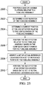
- a method for positioning an end effector relative to a fuselage assembly comprising: identifying fuselage target locations for fuselage laser targets attached to the interior or exterior of the fuselage assembly to thereby determine a configuration of the fuselage assembly; positioning the end effector relative to the fuselage assembly based on the configuration determined; defining a set of reference points, each reference point being a point on a reference fastener located at a reference location on the fuselage assembly; identifying a set of actual reference locations for the set of reference points on the fuselage assembly, each of the set of actual reference locations being a computed value of each of the set of reference points with respect to the configuration; and positioning the end effector at an operation location based on the set of actual reference locations identified.
- determining the configuration comprises: identifying fuselage target locations for fuselage laser targets associated with the fuselage assembly.
- identifying the fuselage target locations comprises: receiving laser measurement data from a set of laser tracking devices; and identifying the fuselage target locations for the fuselage laser targets using the laser measurement data.
- the method further comprises: determining a current position of the end effector relative to the configuration of the fuselage assembly; and identifying a set of expected reference locations for the set of reference points based on the configuration of the fuselage assembly.
- positioning the end effector relative to the fuselage assembly comprises: positioning the end effector relative to one of the set of expected reference locations.
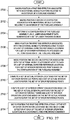
- identifying the set of actual reference locations for the set of reference points comprises: generating imaging data of a reference point of the set of reference points; and computing an actual reference location for the reference point based on the imaging data, wherein generating the imaging data comprises: generating the imaging data using an imaging system while the end effector is positioned relative to an expected reference location for the reference point.
- the method further comprises macro-positioning the end effector relative to the fuselage assembly, wherein macro-positioning the end effector comprises macro-positioning a base of a mobile platform with which the end effector is associated relative to the fuselage assembly.
- the method further comprises driving a base of a mobile platform with which the end effector is associated autonomously into a position relative to one of an interior and an exterior of the fuselage assembly.
- the method further comprises driving a base of a mobile platform with which the end effector is associated inside the fuselage assembly, wherein (A) driving the base comprises driving the base of the mobile platform across a floor within an interior of the fuselage assembly; or (B) driving the base comprises driving the base of the mobile platform from a home position on a tower onto a floor inside the fuselage assembly.
- positioning the end effector relative to the fuselage assembly comprises moving the end effector from a default position with respect to a base of a mobile platform with which the end effector is associated to a position relative to an expected reference location for a reference point of the set of reference points.
- positioning the end effector relative to the operation location comprises: micro-positioning a tool center point located at an end of the end effector relative to the operation location.
- positioning the end effector relative to the fuselage assembly comprises: meso-positioning the end effector relative to each of a set of expected reference locations for the set of reference points on the fuselage assembly, wherein (A) identifying the set of actual reference locations comprises: generating imaging data for a reference point of the set of reference points when the end effector is positioned relative to the reference point; and computing the set of actual reference locations for the set of reference points using the imaging data; or (B) positioning the end effector relative to the operation location comprises: computing the operation location based on the set of actual reference locations for the set of reference points; and positioning the end effector relative to the operation location.
- an apparatus comprising: a fuselage assembly; a laser tracking system comprising a set of laser tracking devices, fuselage laser targets attached to the interior or exterior of the fuselage assembly, and platform laser targets attached to a base of a mobile platform; a control system that controls positioning of an end effector of the mobile platform relative to the fuselage assembly based on laser measurement data that identifies fuselage target locations and is generated by the set of laser tracking devices; and a set of reference fasteners, each reference fastener defining a reference point at a reference location on the fuselage assembly, wherein the control system also controls the positioning of the end effector based on the set of actual reference locations identified.
- the illustrative embodiments recognize and take into account different considerations. For example, the illustrative embodiments recognize and take into account that it may be desirable to automate the process of building a fuselage assembly for an aircraft. Automating the process of building a fuselage assembly for an aircraft may improve build efficiency, improve build quality, and reduce costs associated with building the fuselage assembly. The illustrative embodiments also recognize and take into account that automating the process of building a fuselage assembly may improve the accuracy and precision with which assembly operations are performed, thereby ensuring improved compliance with outer mold line (OML) requirements and inner mold line (IML) requirements for the fuselage assembly.
- OML outer mold line
- IML inner mold line
- automating the process used to build a fuselage assembly for an aircraft may significantly reduce the amount of time needed for the build cycle.
- automating fastening operations may reduce and, in some cases, eliminate, the need for human operators to perform these fastening operations as well as other types of assembly operations.
- this type of automation of the process for building a fuselage assembly for an aircraft may be less labor-intensive, time-consuming, ergonomically challenging, and expensive than performing this process primarily manually. Reduced manual labor may have a desired benefit for the human laborer. Additionally, automating the fuselage assembly process may allow fuselage assemblies to be built in desired assembly facilities and factories at desired assembly rates and desired assembly costs.
- the illustrative embodiments also recognize and take into account that it may be desirable to use equipment that can be autonomously driven and operated to automate the process of building a fuselage assembly.
- an autonomous flexible manufacturing system comprised of mobile systems that may be autonomously driven across a factory floor, autonomously positioned relative to the factory floor as needed for building the fuselage assembly, autonomously operated to build the fuselage assembly, and then autonomously driven away when building of the fuselage assembly has been completed.
- performing any operation, action, or step autonomously may mean performing that operation substantially without any human input.
- a platform that may be autonomously driven is a platform that may be driven substantially independently of any human input.
- an autonomously drivable platform may be a platform that is capable of driving or being driven substantially independently of human input.
- the illustrative embodiments provide a method, apparatus, and system for building a fuselage assembly for an aircraft.
- the illustrative embodiments provide an autonomous flexible manufacturing system that automates most, if not all, of the process of building a fuselage assembly.
- the autonomous flexible manufacturing system may automate the process of installing fasteners to join fuselage skin panels and a fuselage support structure together to build the fuselage assembly.
- the illustrative embodiments provide a flexible manufacturing system that allows a fuselage assembly to be built in an austere manufacturing facility.
- the illustrative embodiments recognize and take into account that automating the process for building a fuselage assembly using an autonomous flexible manufacturing system may present unique technical challenges that require unique technical solutions.
- the illustrative embodiments recognize and take into account that it may be desirable to provide utilities to all of the various systems within the autonomous flexible manufacturing system. In particular, it may be desirable to provide these utilities in a manner that will not disrupt or delay the process of building the fuselage assembly or restrict the movement of various mobile systems within the autonomous flexible manufacturing system over a factory floor.
- the infrastructure may include a utility fixture that provides a direct connection to each of the set of utility sources and an assembly area with a floor space sufficiently large to allow the various systems of an autonomous flexible manufacturing system to be coupled to the utility fixture and each other in series.
- the set of utilities may flow from the set of utility sources to the utility fixture and then downstream to the various systems of the autonomous flexible manufacturing system within the assembly area.
- the illustrative embodiments provide a distributed utility network that may be used to provide utilities to the various systems of the autonomous flexible manufacturing system.
- the distributed utility network may provide these utilities in a manner that does not restrict or impede movement of the various mobile systems of the autonomous flexible manufacturing system.
- the different mobile systems of the autonomous flexible manufacturing system may be autonomously coupled to each other to create this distributed utility network.
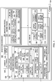
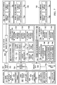
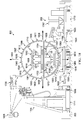
- FIG. 1-7 illustrations of a manufacturing environment are depicted in the form of block diagrams in accordance with an illustrative embodiment.
- a fuselage assembly a flexible manufacturing system
- the various systems within the flexible manufacturing system that may be used to build the fuselage assembly and a distributed utility network are described.
- manufacturing environment 100 may be an example of one environment in which at least a portion of fuselage 102 may be manufactured for aircraft 104.
- Manufacturing environment 100 may take a number of different forms.
- manufacturing environment 100 may take the form of a factory, a manufacturing facility, an outdoor factory area, an enclosed manufacturing area, an offshore platform, or some other type of manufacturing environment 100 suitable for building at least a portion of fuselage 102.
- Fuselage 102 may be built using manufacturing process 108.
- Flexible manufacturing system 106 may be used to implement at least a portion of manufacturing process 108.
- manufacturing process 108 may be substantially automated using flexible manufacturing system 106. In other illustrative examples, only one or more stages of manufacturing process 108 may be substantially automated.
- Flexible manufacturing system 106 may be configured to perform at least a portion of manufacturing process 108 autonomously. In this manner, flexible manufacturing system 106 may be referred to as autonomous flexible manufacturing system 112. In other illustrative examples, flexible manufacturing system 106 may be referred to as an automated flexible manufacturing system.
- manufacturing process 108 may include assembly process 110 for building fuselage assembly 114.
- Flexible manufacturing system 106 may be configured to perform at least a portion of assembly process 110 autonomously.
- Fuselage assembly 114 may be fuselage 102 at any stage during manufacturing process 108 prior to the completion of manufacturing process 108. In some cases, fuselage assembly 114 may be used to refer to a partially assembled fuselage 102. Depending on the implementation, one or more other components may need to be attached to fuselage assembly 114 to fully complete the assembly of fuselage 102. In other cases, fuselage assembly 114 may be used to refer to the fully assembled fuselage 102. Flexible manufacturing system 106 may build fuselage assembly 114 up to the point needed to move fuselage assembly 114 to a next stage in the manufacturing process for building aircraft 104. In some cases, at least a portion of flexible manufacturing system 106 may be used at one or more later stages in the manufacturing process for building aircraft 104.
- fuselage assembly 114 may be an assembly for forming a particular section of fuselage 102.
- fuselage assembly 114 may take the form of aft fuselage assembly 116 for forming an aft section of fuselage 102.
- fuselage assembly 114 may take the form of forward fuselage assembly 117 for forming a forward section of fuselage 102.
- fuselage assembly 114 may take the form of middle fuselage assembly 118 for forming a center section of fuselage 102 or some other middle section of fuselage 102 between the aft and forward sections of fuselage 102.
- fuselage assembly 114 may include plurality of panels 120 and support structure 121.
- Support structure 121 may be comprised of plurality of members 122.
- Plurality of members 122 may be used to both support plurality of panels 120 and connect plurality of panels 120 to each other.
- Support structure 121 may help provide strength, stiffness, and load support for fuselage assembly 114.
- Plurality of members 122 may be associated with plurality of panels 120. As used herein, when one component or structure is "associated" with another component or structure, the association is a physical association in the depicted examples.
- a first component such as one of plurality of members 122
- a second component such as one of plurality of panels 120
- the first component also may be connected to the second component using one or more other components.
- the first component may be connected to the second component using a third component.
- the first component may be considered to be associated with the second component by being formed as part of the second component, an extension of the second component, or both.
- the first component may be considered part of the second component by being co-cured with the second component.
- the phrase "at least one of,” when used with a list of items, means different combinations of one or more of the listed items may be used and only one of the items in the list may be needed.
- the item may be a particular object, thing, action, process, or category.
- "at least one of” means any combination of items or number of items may be used from the list, but not all of the items in the list may be required.
- “at least one of item A, item B, and item C” or “at least one of item A, item B, or item C” may mean item A; item A and item B; item B; item A, item B, and item C; or item B and item C.
- “at least one of item A, item B, and item C” may mean, for example, without limitation, two of item A, one of item B, and ten of item C; four of item B and seven of item C; or some other suitable combination.
- a member of plurality of members 122 may be associated with at least one of plurality of panels 120 in a number of different ways.
- a member of plurality of members 122 may be attached directly to a single panel, attached to two or more panels, attached to another member that is directly attached to at least one panel, attached to at least one member that is directly or indirectly attached to at least one panel, or associated with at least one of plurality of panels 120 in some other way.
- substantially all or all of plurality of members 122 may be associated with plurality of panels 120 prior to the beginning of assembly process 110 for building fuselage assembly 114.
- a corresponding portion of plurality of members 122 may be associated with each panel of plurality of panels 120 prior to plurality of panels 120 being joined to each other through assembly process 110.
- first portion of plurality of members 122 may be associated with plurality of panels 120 prior to the beginning of assembly process 110.
- Assembly process 110 may include attaching a remaining portion of plurality of members 122 to plurality of panels 120 for at least one of providing support to plurality of panels 120 or connecting plurality of panels 120 together.
- the first portion of plurality of members 122 attached to plurality of panels 120 prior to assembly process 110 and the remaining portion of plurality of members 122 attached to plurality of panels 120 during assembly process 110 may together form support structure 121.
- all of plurality of members 122 may be associated with plurality of panels 120 during assembly process 110.
- each of plurality of panels 120 may be "naked" without any members attached to or otherwise associated with the panel prior to assembly process 110.
- plurality of members 122 may then be associated with plurality of panels 120.
- support structure 121 for fuselage assembly 114 may be built up in a number of different ways.
- Fuselage assembly 114 comprising plurality of panels 120 and support structure 121 is described in greater detail in Figure 2 below.
- Building fuselage assembly 114 may include joining plurality of panels 120 together.
- Joining plurality of panels 120 may be performed in a number of different ways.
- joining plurality of panels 120 together may include joining one or more of plurality of members 122 to one or more of plurality of panels 120 or to other members of plurality of members 122.
- joining plurality of panels 120 may include joining at least one panel to at least one other panel, joining at least one member to at least one other member, or joining at least one member to at least one panel, or some combination thereof.
- joining a first panel and a second panel together may include at least one of the following: fastening the first panel directly to the second panel, joining a first member associated with the first panel to a second member associated with the second panel, joining a member associated with the first panel directly to the second panel, joining one member associated with both the first panel and the second panel to another member, joining a selected member to both the first panel and the second panel, or some other type of joining operation.
- Assembly process 110 may include operations 124 that may be performed to join plurality of panels 120 together to build fuselage assembly 114.
- flexible manufacturing system 106 may be used to perform at least a portion of operations 124 autonomously.
- Operations 124 may include, for example, but are not limited to, temporary connection operations 125, drilling operations 126, fastener insertion operations 128, fastener installation operations 130, inspection operations 132, other types of assembly operations, or some combination thereof.
- Temporary connection operations 125 may be performed to temporarily connect plurality of panels 120 together.
- temporary connection operations 125 may include temporarily tacking plurality of panels 120 together using tack fasteners.
- Drilling operations 126 may include drilling holes through one or more of plurality of panels 120 and, in some cases, through one or more of plurality of members 122.
- Fastener insertion operations 128 may include inserting fasteners into the holes drilled by drilling operations 126.
- Fastener installation operations 130 may include fully installing each of the fasteners that have been inserted into the holes.
- Fastener installation operations 130 may include, for example, without limitation, riveting operations, interference-fit bolting operations, other types of fastener installation operations, or some combination thereof.
- Inspection operations 132 may include inspecting the fully installed fasteners.
- flexible manufacturing system 106 may be used to perform any number of these different types of operations 124 substantially autonomously.
- flexible manufacturing system 106 may include plurality of mobile systems 134, control system 136, and utility system 138.
- Each of plurality of mobile systems 134 may be a drivable mobile system.
- each of plurality of mobile systems 134 may be an autonomously drivable mobile system.
- each of plurality of mobile systems 134 may include one or more components that may be autonomously driven within manufacturing environment 100 from one location to another location. Plurality of mobile systems 134 are described in greater detail in Figure 3 below.
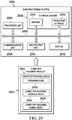
- control system 136 may be used to control the operation of flexible manufacturing system 106.
- control system 136 may be used to control plurality of mobile systems 134.
- control system 136 may be used to direct the movement of each of plurality of mobile systems 134 within manufacturing environment 100.
- Control system 136 may be at least partially associated with plurality of mobile systems 134.
- control system 136 may include set of controllers 140.
- a "set of" items may include one or more items.
- set of controllers 140 may include one or more controllers.
- Each of set of controllers 140 may be implemented using hardware, firmware, software, or some combination thereof.
- set of controllers 140 may be associated with plurality of mobile systems 134.
- one or more of set of controllers 140 may be implemented as part of plurality of mobile systems 134.
- one or more of set of controllers 140 may be implemented independently of plurality of mobile systems 134.
- Set of controllers 140 may generate commands 142 to control the operation of plurality of mobile systems 134 of flexible manufacturing system 106.
- Set of controllers 140 may communicate with plurality of mobile systems 134 using at least one of a wireless communications link, a wired communications link, an optical communications link, or other type of communications link. In this manner, any number of different types of communications links may be used for communication with and between set of controllers 140.
- control system 136 may control the operation of plurality of mobile systems 134 using data 141 received from sensor system 133.
- Sensor system 133 may be comprised of any number of individual sensor systems, sensor devices, controllers, other types of components, or combination thereof.
- sensor system 133 may include laser tracking system 135 and radar system 137.
- Laser tracking system 135 may be comprised of any number of laser tracking devices, laser targets, or combination thereof.
- Radar system 137 may be comprised of any number of radar sensors, radar targets, or combination thereof.
- Sensor system 133 may be used to coordinate the movement and operation of the various mobile systems in plurality of mobile systems 134 within manufacturing environment 100.
- radar system 137 may be used for macro-positioning mobile systems, systems within mobile systems, components within mobile systems, or some combination thereof.
- laser tracking system 135 may be used for micro-positioning mobile systems, systems within mobile systems, components within mobile systems, or some combination thereof.
- Plurality of mobile systems 134 may be used to form distributed utility network 144. Depending on the implementation, one or more of plurality of mobile systems 134 may form distributed utility network 144. Number of utilities 146 may flow from number of utility sources 148 to the various mobile systems of plurality of mobile systems 134 that make up distributed utility network 144.
- each of number of utility sources 148 may be located with manufacturing environment 100. In other illustrative examples, one or more of number of utility sources 148 may be located outside of manufacturing environment 100. The corresponding utility provided by these one or more utility sources may then be carried into manufacturing environment 100 using, for example, without limitation, one or more utility cables.
- distributed utility network 144 may allow number of utilities 146 to flow directly from number of utility sources 148 to one mobile system in plurality of mobile systems 134 over some number of utility cables. This one mobile system may then distribute number of utilities 146 to other mobile systems of plurality of mobile systems 134 such that these other mobile systems do not need to directly receive number of utilities 146 from number of utility sources 148.
- distributed utility network 144 may be formed using utility system 138.
- Utility system 138 may include utility fixture 150.
- Utility system 138 may be configured to connect to number of utility sources 148 such that number of utilities 146 may flow from number of utility sources 148 to utility fixture 150.
- Utility fixture 150 may be above-ground or in-ground, depending on the implementation.
- utility fixture 150 may be embedded in a floor within manufacturing environment 100.
- Utility fixture 150 may then distribute number of utilities 146 to one or more of plurality of mobile systems 134.
- one autonomous coupling of one of plurality of mobile systems 134 to utility fixture 150 may be followed by any number of autonomous couplings of mobile systems to each other in series to form distributed utility network 144.
- Utility fixture 150 may distribute number of utilities 146 to each of plurality of mobile systems 134 downstream of utility fixture 150 in the series of autonomous couplings of the mobile systems.
- distributed utility network 144 may have a chain-like configuration or a tree-like configuration.
- plurality of mobile systems 134 may include mobile systems A, B, C, and D (not shown in figure) with mobile system A autonomously coupled to utility fixture 150 and mobile systems B, C, and D autonomously coupled to mobile system A and each other in series.
- An example of a chain-like configuration for distributed utility network 144 may include number of utilities 146 flowing from number of utility sources 148 over some number of utility cables to utility fixture 150, from utility fixture 150 to mobile system A, from mobile system A to mobile system B, from mobile system B to mobile system C, and from mobile system C to mobile system D.
- An example of a tree-like configuration for distributed utility network 144 may include number of utilities 146 flowing from number of utility sources 148 over some number of utility cables to utility fixture 150, from utility fixture 150 to mobile system A, from mobile system A to both mobile system B and mobile system C, and from mobile system C to mobile system D.
- An example of one manner in which distributed utility network 144 may be implemented using plurality of mobile systems 134 is described in greater detail in Figure 5 below.
- multiple flexible manufacturing systems may be used to build multiple fuselage assemblies concurrently.
- flexible manufacturing system 106 may be a first flexible manufacturing system of many flexible manufacturing systems.
- flexible manufacturing system 106, second flexible manufacturing system 152, and third flexible manufacturing system 154 may be used to build aft fuselage assembly 116, middle fuselage assembly 118, and forward fuselage assembly 117, respectively. Aft fuselage assembly 116, middle fuselage assembly 118, and forward fuselage assembly 117 may then be joined together to form a fully assembled fuselage 102. In this manner, in this example, flexible manufacturing system 106, second flexible manufacturing system 152, and third flexible manufacturing system 154 may together form flexible fuselage manufacturing system 158.
- any number of fuselage assemblies such as fuselage assembly 114, may be built within manufacturing environment 100 using any number of flexible manufacturing systems implemented in a manner similar to flexible manufacturing system 106.
- any number of full fuselages such as fuselage 102, may be built within manufacturing environment 100 using any number of flexible fuselage manufacturing systems implemented in a manner similar to flexible fuselage manufacturing system 158.
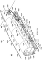
- fuselage assembly 114 may include plurality of panels 120 and support structure 121.
- Fuselage assembly 114 may be used to refer to any stage in the building of fuselage assembly 114.
- fuselage assembly 114 may be used to refer to a single one of plurality of panels 120, multiple ones of plurality of panels 120 that have been or are being joined together, a partially built fuselage assembly, or a fully built fuselage assembly.
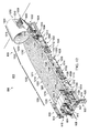
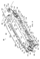
- fuselage assembly 114 may be built such that fuselage assembly 114 has plurality of fuselage sections 205.
- Each of plurality of fuselage sections 205 may include one or more of plurality of panels 120.
- each of plurality of fuselage sections 205 may take the form of a cylindrically-shaped fuselage section, a barrel-shaped fuselage section, a tapered cylindrical fuselage section, a cone-shaped fuselage section, a dome-shaped fuselage section, or a section having some other type of shape.
- a fuselage section of plurality of fuselage sections 205 may have a shape that has a substantially circular cross-sectional shape, elliptical cross-sectional shape, oval cross-sectional shape, polygon with rounded corners cross-sectional shape, or otherwise closed-curve cross-sectional shape.
- each of plurality of fuselage sections 205 may be a portion of fuselage assembly 114 defined between two radial cross-sections of fuselage assembly 114 that are taken substantially perpendicular to a center axis or longitudinal axis through fuselage assembly 114. In this manner, plurality of fuselage sections 205 may be arranged along the longitudinal axis of fuselage assembly 114. In other words, plurality of fuselage sections 205 may be arranged longitudinally.
- Fuselage section 207 may be an example of one of plurality of fuselage sections 205.
- Fuselage section 207 may be comprised of one or more of plurality of panels 120.
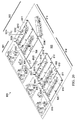
- multiple panel sections may be arranged circumferentially around fuselage section 207 to form the skin of fuselage section 207.
- multiple rows of two or more longitudinally adjacent panels may be arranged circumferentially around fuselage section 207 to form the skin of fuselage section 207.
- fuselage assembly 114 may have crown 200, keel 202, and sides 204.
- Sides 204 may include first side 206 and second side 208.
- Crown 200 may be the top portion of fuselage assembly 114.
- Keel 202 may be the bottom portion of fuselage assembly 114.
- Sides 204 of fuselage assembly 114 may be the portions of fuselage assembly 114 between crown 200 and keel 202.
- each of crown 200, keel 202, first side 206, and second side 208 of fuselage assembly 114 may be formed by at least a portion of at least one of plurality of panels 120. Further, a portion of each of plurality of fuselage sections 205 may form each of crown 200, keel 202, first side 206, and second side 208.
- Panel 216 may be an example of one of plurality of panels 120. Panel 216 may also be referred to as a skin panel, a fuselage panel, or a fuselage skin panel, depending on the implementation. In some illustrative examples, panel 216 may take the form of a mega-panel comprised of multiple smaller panels, which may be referred to as sub-panels. A mega-panel may also be referred to as a super panel. In these illustrative examples, panel 216 may be comprised of at least one of a metal, a metal alloy, some other type of metallic material, a composite material, or some other type of material. As one illustrative example, panel 216 may be comprised of an aluminum alloy, steel, titanium, a ceramic material, a composite material, some other type of material, or some combination thereof.
- panel 216 When used to form keel 202 of fuselage assembly 114, panel 216 may be referred to as a keel panel or a bottom panel. When used to form one of sides 204 of fuselage assembly 114, panel 216 may be referred to as a side panel. When used to form crown 200 of fuselage assembly 114, panel 216 may be referred to as a crown panel or a top panel. As one illustrative example, plurality of panels 120 may include crown panels 218 for forming crown 200, side panels 220 for forming sides 204, and keel panels 222 for forming keel 202. Side panels 220 may include first side panels 224 for forming first side 206 and second side panels 226 for forming second side 208.
- fuselage section 207 of plurality of fuselage sections 205 of fuselage assembly 114 may include one of crown panels 218, two of side panels 220, and one of keel panels 222. In another illustrative example, fuselage section 207 may form an end of fuselage assembly 114.
- fuselage section 207 may be comprised solely of a single panel, such as panel 216.
- panel 216 may take the form of end panel 228.
- End panel 228 may be used to form one end of fuselage assembly 114.
- end panel 228 may form the aftmost end of fuselage assembly 114.
- end panel 228 may form the forwardmost end of fuselage assembly 114.
- end panel 228 may take the form of a cylindrically-shaped panel, a cone-shaped panel, a barrel-shaped panel, or a tapered cylindrical panel.
- end panel 228 may be a single cylindrically-shaped panel having a substantially circular cross-sectional shape that may change in diameter with respect to a center axis for fuselage assembly 114.
- fuselage section 207 may be comprised solely of end panel 228.
- fuselage section 207 may be an end fuselage section that is comprised of only a single panel, which may be end panel 228.
- bulkhead 272 may be associated with end panel 228 when fuselage section 207 is an end fuselage section.
- Bulkhead 272 which may also be referred to as a pressure bulkhead, may be considered separate from or part of end panel 228, depending on the implementation. Bulkhead 272 may have a dome-type shape in these illustrative examples.
- bulkhead 272 may be part of fuselage section 207 located at the aftmost end of aft fuselage assembly 116.
- bulkhead 272 may be part of fuselage section 207 located at forwardmost end of aft fuselage assembly 116.
- Middle fuselage assembly 118 in Figure 1 may not include a bulkhead, such as bulkhead 272, at either end of middle fuselage assembly 118. In this manner, plurality of fuselage sections 205 may be implemented in any number of different ways.
- Panel 216 may have first surface 230 and second surface 232.
- First surface 230 may be configured for use as an exterior-facing surface. In other words, first surface 230 may be used to form exterior 234 of fuselage assembly 114.
- Second surface 232 may be configured for use as an interior-facing surface. In other words, second surface 232 may be used to form interior 236 of fuselage assembly 114.
- Each of plurality of panels 120 may be implemented in a manner similar to panel 216.
- support structure 121 may be associated with a corresponding one of plurality of panels 120.
- Support structure 121 may be comprised of plurality of members 122 that are associated with panel 216.
- corresponding portion 240 may be the portion of plurality of members 122 that correspond to panel 216.
- Corresponding portion 240 may form support section 238 corresponding to panel 216.
- Support section 238 may form a part of support structure 121.
- Plurality of members 122 may include support members 242.
- Support members 242 may include, for example, without limitation, at least one of connecting members 244, frames 246, stringers 248, stiffeners 250, stanchions 252, intercostal structural members 254, or other types of structural members.
- Connecting members 244 may connect other types of support members 242 together. In some cases, connecting members 244 may also connect support members 242 to plurality of panels 120. Connecting members 244 may include, for example, without limitation, shear clips 256, ties 258, splices 260, intercostal connecting members 262, other types of mechanical connecting members, or some combination thereof.
- connecting members 244 may be used to, for example, without limitation, connect together complementary frames of frames 246 running in the hoop-wise direction on adjacent sub-panels and complementary stringers of stringers 248 running in the longitudinal direction on adjacent sub-panels.
- connecting members 244 may be used to connect together complementary frames, stringers, or other types of support members on two or more adjacent panels in plurality of panels 120.
- connecting members 244 may be used to connect together complementary support members on two or more adjacent fuselage sections.
- Operations 124 may be performed to join plurality of panels 120 together to build fuselage assembly 114.
- plurality of fasteners 264 may be used to join plurality of panels 120 together.
- joining plurality of panels 120 together may be performed in a number of different ways.
- Joining plurality of panels 120 together may include at least one of joining at least one panel in plurality of panels 120 to another one of plurality of panels 120, joining at least one panel in plurality of panels 120 to at least one of plurality of members 122, joining at least one member in plurality of members 122 to another one of plurality of members 122, or some other type of joining operation.
- Plurality of panels 120 may be joined together such that plurality of members 122 ultimately form support structure 121 for fuselage assembly 114.
- number of floors 266 may be associated with fuselage assembly 114.
- number of floors 266 may be part of fuselage assembly 114.
- Number of floors 266 may include, for example, without limitation, at least one of a passenger floor, a cargo floor, or some other type of floor.
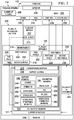
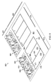
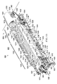
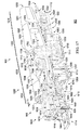
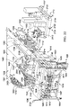
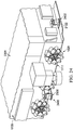
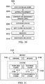
- FIG. 3 an illustration of plurality of mobile systems 134 of flexible manufacturing system 106 within manufacturing environment 100 from Figure 1 is depicted in the form of a block diagram in accordance with an illustrative embodiment.
- flexible manufacturing system 106 may be used to build fuselage assembly 114 on floor 300 of manufacturing environment 100.
- floor 300 may be referred to as factory floor 302.
- floor 300 may be substantially smooth and substantially planar.
- floor 300 may be substantially level.
- one or more portions of floor 300 may be sloped, ramped, or otherwise uneven.
- Assembly area 304 may be an area within manufacturing environment 100 designated for performing assembly process 110 in Figure 1 to build a fuselage assembly, such as fuselage assembly 114.
- Assembly area 304 may also be referred to as a cell or a work cell.
- assembly area 304 may be a designated area on floor 300.
- assembly area 304 may include a designated area on floor 300 as well as the area above this designated area. Any number of assembly areas may be present within manufacturing environment 100 such that any number of fuselage assemblies may be built concurrently within manufacturing environment 100.
- plurality of mobile systems 134 may include plurality of autonomous vehicles 306, cradle system 308, tower system 310, and autonomous tooling system 312.
- Each of plurality of mobile systems 134 may be drivable across floor 300.
- each of plurality of mobile systems 134 may be capable of being autonomously driven across floor 300 from one location 315 to another location 317 on floor 300.
- each of plurality of autonomous vehicles 306 may take the form of an automated guided vehicle (AGV), which may be capable of operating independently without human direction or guidance.
- AGV automated guided vehicle
- plurality of autonomous vehicles 306 may be referred to as a plurality of automated guided vehicles (AGVs) .
- cradle system 308 may be used to support and hold fuselage assembly 114 during assembly process 110 in Figure 1 .
- cradle system 308 may be referred to as a drivable cradle system.
- cradle system 308 may be referred to as an autonomously drivable cradle system.
- Cradle system 308 may include number of fixtures 313.
- a "number of" items may include one or more items.
- number of fixtures 313 may include one or more fixtures.
- number of fixtures 313 may be referred to as a number of drivable fixtures.
- number of fixtures 313 may be referred to as a number of autonomously drivable fixtures.
- Number of fixtures 313 may include number of cradle fixtures 314.
- number of cradle fixtures 314 may be referred to as a number of drivable cradle fixtures.
- number of cradle fixtures 314 may be referred to as a number of autonomously drivable cradle fixtures.
- Cradle fixture 322 may be an example of one of number of cradle fixtures 314.
- Number of retaining structures 326 may be associated with each of number of cradle fixtures 314. Number of retaining structures 326 associated with each of number of cradle fixtures 314 may be engaged with and used to support fuselage assembly 114. For example, number of retaining structures 326 associated with cradle fixture 322 may be engaged with and used to support one or more of plurality of panels 120.
- Number of cradle fixtures 314 may be autonomously driven across floor 300 of manufacturing environment 100 to assembly area 304.
- each of number of cradle fixtures 314 may be autonomously driven across floor 300 using a corresponding one of plurality of autonomous vehicles 306.
- number of corresponding autonomous vehicles 316 in plurality of autonomous vehicles 306 may be used to drive number of cradle fixtures 314 across floor 300 into assembly area 304.
- number of corresponding autonomous vehicles 316 may drive from, for example, without limitation, holding area 318, across floor 300, to assembly area 304.
- Holding area 318 may be an area in which at least one of plurality of autonomous vehicles 306, cradle system 308, tower system 310, autonomous tooling system 312, or control system 136 from Figure 1 may be held when flexible manufacturing system 106 is not in use or when that particular device or system is not in use.
- Holding area 318 may be referred to as a home area, a storage area, or a base area, depending on the implementation. Although holding area 318 is depicted as being located within manufacturing environment 100, holding area 318 may be located in some other area or environment outside of manufacturing environment 100 in other illustrative examples.
- Number of corresponding autonomous vehicles 316 in plurality of autonomous vehicles 306 may drive number of cradle fixtures 314 into number of selected cradle positions 320.
- a "position" may be comprised of a location, an orientation, or both.
- the location may be in two-dimensional coordinates or three-dimensional coordinates with respect to a reference coordinate system.
- the orientation may be a two-dimensional or three-dimensional orientation with respect to a reference coordinate system.
- This reference coordinate system may be, for example, without limitation, a fuselage coordinate system, an aircraft coordinate system, a coordinate system for manufacturing environment 100, or some other type of coordinate system.
- cradle fixtures 314 When number of cradle fixtures 314 includes more than one cradle fixture such that number of selected cradle positions 320 includes more than one cradle position, these cradle positions may be positions selected relative to each other. In this manner, number of cradle fixtures 314 may be positioned such that number of cradle fixtures 314 are in number of selected cradle positions 320 relative to each other.
- number of corresponding autonomous vehicles 316 may be used to drive number of cradle fixtures 314 into number of selected cradle positions 320 within assembly area 304.
- "Driving" a component or a system across floor 300 may mean, for example, but not limited to, moving substantially the entirety of that component or system from one location to another location.
- driving cradle fixture 322 across floor 300 may mean moving the entirety of cradle fixture 322 from one location to another location.
- all or substantially all components that comprise cradle fixture 322 may be simultaneously moved together from one location to another location.
- number of cradle fixtures 314 may be coupled to each other and to tower system 310.
- Number of corresponding autonomous vehicles 316 may then drive away from number of cradle fixtures 314 to, for example, without limitation, holding area 318, once number of cradle fixtures 314 is positioned in number of selected cradle positions 320 within selected tolerances.
- number of corresponding autonomous vehicles 316 may be comprised of a single autonomous vehicle that is used to drive each of number of cradle fixtures 314 into a corresponding selected position in number of selected cradle positions 320 within assembly area 304 one at a time.
- number of cradle fixtures 314 may be configured to form assembly fixture 324.
- Assembly fixture 324 may be formed when the different cradle fixtures in number of cradle fixtures 314 have been placed in number of selected cradle positions 320 relative to each other. In some cases, assembly fixture 324 may be formed when number of cradle fixtures 314 have been coupled to each other while number of cradle fixtures 314 is in number of selected cradle positions 320 and when number of retaining structures 326 associated with each of number of cradle fixtures 314 has been adjusted to receive fuselage assembly 114.
- assembly fixture 324 may be used to support and hold fuselage assembly 114.
- assembly fixture 324 may be referred to as an assembly fixture system or a fixture system.
- assembly fixture 324 may be referred to as a drivable assembly fixture.
- assembly fixture 324 may be referred to as an autonomously drivable assembly fixture.
- number of cradle fixtures 314 may receive fuselage assembly 114.
- plurality of fuselage sections 205 may be engaged with number of cradle fixtures 314.
- plurality of fuselage sections 205 may be engaged with number of retaining structures 326 associated with each of number of cradle fixtures 314.
- Plurality of fuselage sections 205 may be engaged with number of cradle fixtures 314 in any number of ways.
- each cradle fixture may be used to support and hold substantially the entire fuselage assembly 114.
- each of these cradle fixtures may be used to support and hold at least one corresponding fuselage section of plurality of fuselage sections 205.
- each of plurality of fuselage sections 205 may be engaged with number of cradle fixtures 314 one at a time.
- all of the panels for a particular fuselage section in plurality of fuselage sections 205 may be positioned relative to each other and a corresponding cradle fixture in number of cradle fixtures 314 and then engaged with the corresponding cradle fixture.
- the remaining fuselage sections in plurality of fuselage sections 205 may then be formed and engaged with number of cradle fixtures 314 in a similar manner.
- plurality of panels 120 may be engaged with number of cradle fixtures 314 by engaging at least a portion of plurality of panels 120 with number of retaining structures 326 associated with each of number of cradle fixtures 314 that makes up assembly fixture 324 such that plurality of panels 120 is supported by number of cradle fixtures 314.
- plurality of panels 120 may include keel panels 222, side panels 220, and crown panels 218.
- all of keel panels 222 in Figure 2 used to form keel 202 of fuselage assembly 114 in Figure 2 may first be positioned relative to and engaged with number of cradle fixtures 314.
- all of side panels 220 in Figure 2 used to form sides 204 of fuselage assembly 114 in Figure 2 may be positioned relative to and engaged with keel panels 222.
- all of crown panels 218 in Figure 2 used to form crown 200 of fuselage assembly 114 in Figure 2 may be positioned relative to and engaged with side panels 220.
- plurality of fuselage sections 205 may be concurrently assembled to form fuselage assembly 114.
- each panel in plurality of panels 120 may have a corresponding portion of plurality of members 122 fully formed and associated with the panel prior to the panel being engaged with one of number of cradle fixtures 314.
- This corresponding portion of plurality of members 122 may be referred to as a support section.
- support section 238 in Figure 2 may be fully formed and associated with panel 216 in Figure 2 prior to panel 216 being engaged with one of number of cradle fixtures 314 or another panel of plurality of panels 120 in Figure 2 .
- a corresponding portion of support members 242 in Figure 2 may already be attached to panel 216 and a corresponding portion of connecting members 244 in Figure 2 already installed to connect this portion of support members 242 to each other prior to panel 216 from Figure 2 being engaged with one of number of cradle fixtures 314.
- plurality of members 122 may be associated with plurality of panels 120 after plurality of panels 120 have been engaged with each other and number of cradle fixtures 314. In still other illustrative examples, only a portion of plurality of members 122 may be associated with plurality of panels 120 prior to plurality of panels 120 being engaged with each other and number of cradle fixtures 314 and then a remaining portion of plurality of members 122 associated with plurality of panels 120 once plurality of panels 120 have been engaged with each other and number of cradle fixtures 314.
- one or more of support members 242 in Figure 2 , one or more of connecting members 244 in Figure 2 , or both may not be associated with panel 216 when panel 216 from Figure 2 is engaged with one of number of cradle fixtures 314 or with one of the other panels in plurality of panels 120.
- frames 246 described in Figure 2 may be added to panel 216 from Figure 2 after panel 216 has been engaged with cradle fixture 322.
- stiffeners 250 described in Figure 2 may be added to panel 216 from Figure 2 after panel 216 has been engaged with cradle fixture 322.
- Building fuselage assembly 114 may include engaging plurality of panels 120 with each other as plurality of panels 120 are built up on number of cradle fixtures 314 of assembly fixture 324.
- adjacent panels in plurality of panels 120 may be connected by connecting at least a portion of the support members associated with the panels.
- at least one of lap splices, butt splices, or other types of splices may be used to connect the adjacent panels in addition to or in place of connecting the corresponding support members of the adjacent panels.
- the support members associated with two adjacent panels in plurality of panels 120 may be connected together using connecting members, thereby connecting the two adjacent panels.
- the two support members associated with these two adjacent panels may be, for example, without limitation, spliced, tied, clipped, tacked, pinned, joined, or fastened together in some other manner.
- complementary frames may be connected in the hoop-wise direction.
- complementary stringers may be connected in the longitudinal direction.
- connecting complementary stringers, frames, or other support members on these two adjacent panels may be part of splicing these panels together.
- Adjacent panels may be connected together using any number of panel splices, stringer splices, frame splices, or other types of splices.
- plurality of panels 120 may be temporarily connected to each other by temporarily fastening at least one of plurality of panels 120 or plurality of members 122 together using temporary fasteners or permanent fasteners.
- temporary clamps may be used to temporarily connect and hold in place two of plurality of panels 120 together.
- Temporarily connecting plurality of panels 120 together may be performed by at least one of temporarily connecting at least two plurality of panels 120 together, temporarily connecting at least two plurality of members 122 together, or temporarily connecting at least one of plurality of panels 120 to at least one of plurality of members 122 such that plurality of members 122 associated with plurality of panels 120 forms support structure 121 in Figure 2 for fuselage assembly 114.
- plurality of panels 120 may be temporarily tacked or pinned together using temporary fasteners 328 until plurality of fasteners 264 are installed to join plurality of panels 120 together to form fuselage assembly 114. Temporarily connecting plurality of panels 120 may temporarily connect together plurality of fuselage sections 205 from Figure 2 formed by plurality of panels 120. Once plurality of fasteners 264 have been installed, temporary fasteners 328 may then be removed.
- plurality of panels 120 may be connected together in a number of different ways. Once plurality of panels 120 have been connected together, plurality of members 122 may be considered as forming support structure 121 for fuselage assembly 114. Connecting plurality of panels 120 together and forming support structure 121 may maintain desired compliance with outer mold line requirements and inner mold line requirements for fuselage assembly 114. In other words, plurality of panels 120 may be held together in place relative to each other such that fuselage assembly 114 formed using plurality of panels 120 meets outer mold line requirements and inner mold line requirements for fuselage assembly 114 within selected tolerances.
- assembly fixture 324 may support plurality of panels 120 and support structure 121 associated with plurality of panels 120 such that fuselage assembly 114 built using plurality of panels 120 and support structure 121 has a shape and a configuration that is within selected tolerances. In this manner, this shape and configuration may be maintained within selected tolerances while supporting plurality of panels 120 and plurality of members 122 associated with plurality of panels 120 during the building of fuselage assembly 114.
- This shape may be at least partially determined by, for example, without limitation, the outer mold line requirements and inner mold line requirements for fuselage assembly 114. In some cases, the shape may be at least partially determined by the location and orientation of the frames and stringers of fuselage assembly 114.
- number of corresponding autonomous vehicles 316 may drive assembly fixture 324 out of assembly area 304.
- fuselage assembly 114 may be driven across floor 300 into a different area within manufacturing environment 100, from floor 300 onto another floor in a different manufacturing environment, or from floor 300 onto another floor in some other area or environment.
- assembly fixture 324 may be driven to some other location at which another assembly fixture is located such that the two assembly fixtures may be coupled to form a larger assembly fixture.
- assembly fixture 324 may be used to hold and support aft fuselage assembly 116 in Figure 1
- another assembly fixture implemented in a manner similar to assembly fixture 324 may be used to hold and support forward fuselage assembly 117 in Figure 1
- Yet another assembly fixture implemented in a manner similar to assembly fixture 324 may be used to hold and support middle fuselage assembly 118 in Figure 1 .
- the three assembly fixtures may be brought together to form a larger assembly fixture for holding aft fuselage assembly 116, middle fuselage assembly 118, and forward fuselage assembly 117 such that these three fuselage assemblies may be joined to form fuselage 102 described in Figure 1 .
- this larger assembly fixture may hold aft fuselage assembly 116, middle fuselage assembly 118, and forward fuselage assembly 117 in alignment with each other such that fuselage 102 may be built within selected tolerances.
- a first assembly fixture and a second assembly fixture implemented in a manner similar to assembly fixture 324 may be used to hold and support aft fuselage assembly 116 and forward fuselage assembly 117, respectively, from Figure 1 .
- the two assembly fixtures may then be brought together to form a larger assembly fixture for holding the two fuselage assemblies such that these fuselage assemblies may be joined to form fuselage 102.
- the larger assembly fixture may hold aft fuselage assembly 116 and forward fuselage assembly 117 in alignment with each other such that fuselage 102 may be built within selected tolerances.
- tower system 310 includes number of towers 330.
- Tower 332 may be an example of one implementation for one of number of towers 330.
- Tower 332 may be configured to provide access to interior 236 of fuselage assembly 114 described in Figure 2 .
- tower 332 may be referred to as a drivable tower.
- tower 332 may be referred to as an autonomously drivable tower.
- tower 332 may take the form of first tower 334.
- First tower 334 may also be referred to as an operator tower in some cases.
- tower 332 may take the form of second tower 336.
- Second tower 336 may also be referred to as a robotics tower in some cases.
- number of towers 330 may include both first tower 334 and second tower 336.
- First tower 334 may be configured substantially for use by a human operator, whereas second tower 336 may be configured substantially for use by a mobile platform having at least one robotic device associated with the mobile platform.
- first tower 334 may allow a human operator to access and enter interior 236 of fuselage assembly 114.
- Second tower 336 may allow a mobile platform to access and enter interior 236 of fuselage assembly 114.
- First tower 334 and second tower 336 may be positioned relative to assembly fixture 324 at different times during assembly process 110.
- one of plurality of autonomous vehicles 306 may be used to move or autonomously drive first tower 334 from holding area 318 into selected tower position 338 within assembly area 304.
- Number of cradle fixtures 314 may then be autonomously driven, using number of corresponding autonomous vehicles 316, into number of selected cradle positions 320 relative to first tower 334, which is in selected tower position 338 within assembly area 304.
- Second tower 336 may be exchanged for first tower 334 at some later stage during assembly process 110 in Figure 1 .
- one of plurality of autonomous vehicles 306 may be used to autonomously drive first tower 334 out of assembly area 304 and back into holding area 318.
- the same autonomous vehicle or a different autonomous vehicle in plurality of autonomous vehicles 306 may then be used to autonomously drive second tower 336 from holding area 318 into selected tower position 338 within assembly area 304 that was previously occupied by first tower 334.
- first tower 334 may be later exchanged for second tower 336.
- first tower 334 and second tower 336 may each have an autonomous vehicle in plurality of autonomous vehicles 306 fixedly associated with the tower.
- one of plurality of autonomous vehicles 306 may be integrated with first tower 334 and one of plurality of autonomous vehicles 306 may be integrated with second tower 336.
- one of plurality of autonomous vehicles 306 may be considered part of or built into first tower 334.
- First tower 334 may then be considered capable of autonomously driving across floor 300.
- one of plurality of autonomous vehicles 306 may be considered part of or built into second tower 336.
- Second tower 336 may then be considered capable of autonomously driving across floor 300.
- Tower system 310 and assembly fixture 324 may be configured to form interface 340 with each other.
- Interface 340 may be a physical interface between tower system 310 and assembly fixture 324.
- Tower system 310 may also be configured to form interface 342 with utility system 138.
- interface 340 and interface 342 may be autonomously formed.
- Interface 342 may be a physical interface between tower system 310 and utility system 138.
- interface 340 and interface 342 may also be utility interfaces.
- interface 340 and interface 342 may be considered electrical interfaces.
- Utility system 138 is configured to distribute number of utilities 146 to tower system 310 when tower system 310 and utility system 138 are physically and electrically coupled through interface 342.
- Tower system 310 may then distribute number of utilities 146 to assembly fixture 324 formed by cradle system 308 when assembly fixture 324 and tower system 310 are physically and electrically coupled through interface 340.
- Number of utilities 146 may include at least one of power, air, hydraulic fluid, communications, water, or some other type of utility.
- utility system 138 may include utility fixture 150.
- Utility fixture 150 may be configured to receive number of utilities 146 from number of utility sources 148.
- Number of utility sources 148 may include, for example, without limitation, at least one of a power generator, a battery system, a water system, an electrical line, a communications system, a hydraulic fluid system, an air tank, or some other type of utility source.
- utility fixture 150 may receive power from a power generator.
- utility fixture 150 may be positioned relative to assembly area 304. Depending on the implementation, utility fixture 150 may be positioned inside assembly area 304 or outside of assembly area 304.
- utility fixture 150 may be associated with floor 300. Depending on the implementation, utility fixture 150 may be permanently associated with floor 300 or temporarily associated with floor 300. In other illustrative examples, utility fixture 150 may be associated with some other surface of manufacturing environment 100, such as a ceiling, or some other structure in manufacturing environment 100. In some cases, utility fixture 150 may be embedded within floor 300.
- first tower 334 may be autonomously driven into selected tower position 338 with respect to floor 300 relative to utility fixture 150 such that interface 342 may be formed between first tower 334 and utility fixture 150.
- number of utilities 146 may flow from utility fixture 150 to first tower 334.
- Assembly fixture 324 may then autonomously form interface 340 with first tower 334 to form a network of utility cables between first tower 334 and assembly fixture 324.
- first tower 334 may function as a conduit or "middleman" for distributing number of utilities 146 to assembly fixture 324.
- number of utilities 146 may be provided to second tower 336 and assembly fixture 324 in a similar manner as described above.
- utility fixture 150 may distribute number of utilities 146 to tower system 310 and assembly fixture 324 without tower system 310 and cradle assembly fixture 324 having to separately connect to number of utility sources 148 or any other utility sources.
- Autonomous tooling system 312 may be used to assemble plurality of panels 120 and support structure 121 while fuselage assembly 114 is being supported and held by assembly fixture 324.
- Autonomous tooling system 312 may include plurality of mobile platforms 344.
- Each of plurality of mobile platforms 344 may be configured to perform one or more of operations 124 in assembly process 110 described in Figure 1 .
- plurality of mobile platforms 344 may be autonomously driven into selected positions relative to plurality of panels 120 within selected tolerances to autonomously perform operations 124 that join plurality of panels 120 together to build fuselage assembly 114.
- Plurality of mobile platforms 344 are described in greater detail in Figure 4 below.
- set of controllers 140 in control system 136 may generate commands 142 as described in Figure 1 to control the operation of at least one of cradle system 308, tower system 310, utility system 138, autonomous tooling system 312, or plurality of autonomous vehicles 306.
- Set of controllers 140 in Figure 1 may communicate with at least one of cradle system 308, tower system 310, utility system 138, autonomous tooling system 312, or plurality of autonomous vehicles 306 using any number of wireless communications links, wired communications links, optical communications links, other types of communications links, or combination thereof.
- plurality of mobile systems 134 of flexible manufacturing system 106 may be used to automate the process of building fuselage assembly 114.
- Plurality of mobile systems 134 may enable fuselage assembly 114 to be built substantially autonomously with respect to joining together plurality of panels 120 to reduce the overall time, effort, and human resources needed.
- Flexible manufacturing system 106 may build fuselage assembly 114 up to the point needed to move fuselage assembly 114 to the next stage in manufacturing process 108 for building fuselage 102 or the next stage in the manufacturing process for building aircraft 104, depending on the implementation.
- cradle system 308 in the form of assembly fixture 324 may continue carrying and supporting fuselage assembly 114 during one or more of these later stages in manufacturing process 108 for building fuselage 102 and aircraft 104.
- plurality of mobile platforms 344 may include number of external mobile platforms 400 and number of internal mobile platforms 402. In this manner, plurality of mobile platforms 344 may include at least one external mobile platform and at least one internal mobile platform.
- number of external mobile platforms 400 may be referred to as a number of drivable external mobile platforms.
- number of internal mobile platforms 402 may be referred to as a number of drivable internal mobile platforms.
- number of external mobile platforms 400 and number of internal mobile platforms 402 may be referred to as a number of autonomously drivable external mobile platforms and a number of autonomously drivable internal mobile platforms, respectively.
- External mobile platform 404 may be an example of one of number of external mobile platforms 400 and internal mobile platform 406 may be an example of one of number of internal mobile platforms 402.
- External mobile platform 404 and internal mobile platform 406 may be platforms that are autonomously drivable.
- each of external mobile platform 404 and internal mobile platform 406 may be configured to autonomously drive across floor 300 on its own or with the assistance of one of plurality of autonomous vehicles 306 from Figure 3 .
- external mobile platform 404 may be autonomously driven across floor 300 using a corresponding one of plurality of autonomous vehicles 306.
- external mobile platform 404 and this corresponding one of plurality of autonomous vehicles 306 may be integrated with each other.
- the autonomous vehicle may be fixedly associated with external mobile platform 404.
- An entire load of external mobile platform 404 may be transferable to the autonomous vehicle such that driving the autonomous vehicle across floor 300 drives external mobile platform 404 across floor 300.
- External mobile platform 404 may be driven from, for example, without limitation, holding area 318 to a position relative to exterior 234 of fuselage assembly 114 to perform one or more operations 124 in Figure 1 .
- at least one external robotic device 408 may be associated with external mobile platform 404.
- external robotic device 408 may be considered part of external mobile platform 404.
- external robotic device 408 may be considered a separate component that is physically attached to external mobile platform 404.
- External robotic device 408 may take the form of, for example, without limitation, a robotic arm.
- External robotic device 408 may have first end effector 410.
- Any number of tools may be associated with first end effector 410. These tools may include, for example, without limitation, at least one of a drilling tool, a fastener insertion tool, a fastener installation tool, an inspection tool, or some other type of tool.
- any number of fastening tools may be associated with first end effector 410.
- first tool 411 may be associated with first end effector 410.
- first tool 411 may be any tool that is removably associated with first end effector 410.
- first tool 411 associated with first end effector 410 may be changed as various operations need to be performed.
- first tool 411 may take the form of one type of tool, such as a drilling tool, to perform one type of operation. This tool may then be exchanged with another type of tool, such as a fastener insertion tool, to become the new first tool 411 associated with first end effector 410 to perform a different type of operation.
- first tool 411 may take the form of first riveting tool 412.
- First riveting tool 412 may be used to perform riveting operations.
- a number of different tools may be exchanged with first riveting tool 412 and associated with first end effector 410.
- first riveting tool 412 may be exchangeable with a drilling tool, a fastener insertion tool, a fastener installation tool, an inspection tool, or some other type of tool.
- External mobile platform 404 may be autonomously driven across floor 300 and positioned relative to assembly fixture 324 in Figure 3 supporting fuselage assembly 114 to position first end effector 410 and first tool 411 associated with first end effector 410 relative to one of plurality of panels 120.
- external mobile platform 404 may be autonomously driven across floor 300 to external position 414 relative to assembly fixture 324.
- first tool 411 carried by external mobile platform 404 may be macro-positioned using external mobile platform 404.
- first end effector 410 may be autonomously controlled using at least external robotic device 408 to position first tool 411 associated with first end effector 410 relative to a particular location on an exterior-facing side of one of plurality of panels 120. In this manner, first tool 411 may be micro-positioned relative to the particular location.
- Internal mobile platform 406 may be located on second tower 336 in Figure 3 when internal mobile platform 406 is not in use. When interface 342 described in Figure 3 is formed between second tower 336 and assembly fixture 324, internal mobile platform 406 may be driven from second tower 336 into interior 236 of fuselage assembly 114 and used to perform one or more of operations 124. In one illustrative example, internal mobile platform 406 may have a movement system that allows internal mobile platform 406 to move from second tower 336 onto a floor inside fuselage assembly 114.
- At least one internal robotic device 416 may be associated with internal mobile platform 406.
- internal robotic device 416 may be considered part of internal mobile platform 406.
- internal robotic device 416 may be considered a separate component that is physically attached to internal mobile platform 406.
- Internal robotic device 416 may take the form of, for example, without limitation, a robotic arm.
- Internal robotic device 416 may have second end effector 418. Any number of tools may be associated with second end effector 418. For example, without limitation, at least one of a drilling tool, a fastener insertion tool, a fastener installation tool, an inspection tool, or some other type of tool may be associated with second end effector 418. In particular, any number of fastening tools may be associated with second end effector 418.
- second tool 419 may be associated with second end effector 418.
- second tool 419 may be any tool that is removably associated with second end effector 418.
- second tool 419 associated with second end effector 418 may be changed as various operations need to be performed.
- first tool 411 may take the form of one type of tool, such as a drilling tool, to perform one type of operation. This tool may then be exchanged with another type of tool, such as a fastener insertion tool, to become the new first tool 411 associated with first end effector 410 to perform a different type of operation.
- second tool 419 may take the form of second riveting tool 420.
- Second riveting tool 420 may be associated with second end effector 418.
- Second riveting tool 420 may be used to perform riveting operations.
- a number of different tools may be exchanged with second riveting tool 420 and associated with second end effector 418.
- second riveting tool 420 may be exchangeable with a drilling tool, a fastener insertion tool, a fastener installation tool, an inspection tool, or some other type of tool.
- Internal mobile platform 406 may be driven from second tower 336 into fuselage assembly 114 and positioned relative to interior 236 of fuselage assembly 114 to position second end effector 418 and second tool 419 associated with second end effector 418 relative to one of plurality of panels 120.
- internal mobile platform 406 may be autonomously driven onto one of number of floors 266 in Figure 2 into internal position 422 within fuselage assembly 114 relative to fuselage assembly 114.
- second tool 419 may be macro-positioned into internal position 422 using internal mobile platform 406.
- second end effector 418 may be autonomously controlled to position second tool 419 associated with second end effector 418 relative to a particular location on an interior-facing side of one of plurality of panels 120 or an interior-facing side of one of plurality of members 122 in Figure 2 that make up support structure 121. In this manner, second tool 419 may be micro-positioned relative to the particular location.
- external position 414 for external mobile platform 404 and internal position 422 for internal mobile platform 406 may be selected such that fastening process 424 may be performed at location 426 on fuselage assembly 114 using external mobile platform 404 and internal mobile platform 406.
- location 426 may take the form of operation location 427 that has been computed by control system 136 in Figure 1 .
- Fastening process 424 may include any number of operations.
- fastening process 424 may include at least one of drilling operation 428, fastener insertion operation 430, fastener installation operation 432, inspection operation 434, or some other type of operation.
- drilling operation 428 may be performed autonomously using first tool 411 associated with first end effector 410 of external mobile platform 404 or second tool 419 associated with second end effector 418 of internal mobile platform 406.
- first tool 411 or second tool 419 may take the form of a drilling tool for use in performing drilling operation 428.
- Drilling operation 428 may be autonomously performed using first tool 411 or second tool 419 to form hole 436 at location 426.
- Hole 436 may pass through at least one of two panels in plurality of panels 120, two members of a plurality of members 122, or a panel and one of plurality of members 122.
- Fastener insertion operation 430 may be performed autonomously using first tool 411 associated with first end effector 410 of external mobile platform 404 or second tool 419 associated with second end effector 418 of internal mobile platform 406. Fastener insertion operation 430 may result in fastener 438 being inserted into hole 436.
- Fastener installation operation 432 may then be performed autonomously using at least one of first tool 411 associated with first end effector 410 of external mobile platform 404 or second tool 419 associated with second end effector 418 of internal mobile platform 406.
- fastener installation operation 432 may be performed autonomously using first tool 411 in the form of first riveting tool 412 and second tool 419 in the form of second riveting tool 420 such that fastener 438 becomes rivet 442 installed at location 426.
- Rivet 442 may be a fully installed rivet. Rivet 442 may be one of plurality of fasteners 264 described in Figure 2 .
- fastener installation operation 432 may take the form of bolt-nut type installation process 433.
- First tool 411 associated with first end effector 410 may be used to, for example, without limitation, install bolt 435 through hole 436.
- Second tool 419 associated with second end effector 418 may then be used to install nut 437 over bolt 435.
- installing nut 437 may include applying a torque sufficient to nut 437 such that a portion of nut 437 breaks off. In these cases, nut 437 may be referred to as a frangible collar.
- fastener installation operation 432 may take the form of interference-fit bolt-type installation process 439.
- First tool 411 associated with first end effector 410 may be used to, for example, without limitation, install bolt 435 through hole 436 such that an interference fit is created between bolt 435 and hole 436.
- Second tool 419 associated with second end effector 418 may then be used to install nut 437 over bolt 435.
- fastener installation operation 432 may take the form of two-stage riveting process 444.
- Two-stage riveting process 444 may be performed using, for example, without limitation, first riveting tool 412 associated with external mobile platform 404 and second riveting tool 420 associated with internal mobile platform 406.
- first riveting tool 412 and second riveting tool 420 may be positioned relative to each other by external mobile platform 404 and internal mobile platform 406, respectively.
- external mobile platform 404 and external robotic device 408 may be used to position first riveting tool 412 relative to location 426 at exterior 234 of fuselage assembly 114.
- Internal mobile platform 406 and internal robotic device 416 may be used to position second riveting tool 420 relative to the same location 426 at interior 236 of fuselage assembly 114.
- First riveting tool 412 and second riveting tool 420 may then be used to perform two-stage riveting process 444 to form rivet 442 at location 426.
- Rivet 442 may join at least two of plurality of panels 120 together, a panel in plurality of panels 120 to support structure 121 formed by plurality of members 122, or two panels in plurality of panels 120 to support structure 121.
- two-stage riveting process 444 may be performed at each of plurality of locations 446 on fuselage assembly 114 to install plurality of fasteners 264 as described in Figure 2 .
- Two-stage riveting process 444 may ensure that plurality of fasteners 264 in Figure 2 are installed at plurality of locations 446 with a desired quality and desired level of accuracy.
- internal mobile platform 406 may be autonomously driven and operated inside fuselage assembly 114 to position internal mobile platform 406 and second riveting tool 420 associated with internal mobile platform 406 relative to plurality of locations 446 on fuselage assembly 114 for performing assembly process 110 described in Figure 1 .
- external mobile platform 404 may be autonomously driven and operated around fuselage assembly 114 to position external mobile platform 404 and first riveting tool 412 associated with external mobile platform 404 relative to plurality of locations 446 on fuselage assembly 114 for performing operations 124.
- FIG. 5 an illustration of a flow of number of utilities 146 across distributed utility network 144 from Figure 1 is depicted in the form of a block diagram in accordance with an illustrative embodiment. As depicted, number of utilities 146 may be distributed across distributed utility network 144.
- Distributed utility network 144 may include, for example, without limitation, number of utility sources 148, utility fixture 150, number of towers 330, assembly fixture 324, number of external mobile platforms 400, and number of utility units 500. In some cases, distributed utility network 144 may also include number of internal mobile platforms 402. In some illustrative examples, number of utility sources 148 may be considered separate from distributed utility network 144.
- distributed utility network 144 may be formed when utility fixture 150 is coupled to number of utility sources 148, first tower 334 is coupled to utility fixture 150, assembly fixture 324 is coupled to first tower 334, and number of external mobile platforms 400 is coupled to number of utility units 500.
- Number of utility units 500 may be associated with number of cradle fixtures 314 of assembly fixture 324 or separated from number of cradle fixtures 314.
- a number of dual interfaces may be created between number of external mobile platforms 400, number of utility units 500, and number of cradle fixtures 314 using one or more dual-interface couplers.
- distributed utility network 144 may be formed when utility fixture 150 is coupled to number of utility sources 148, second tower 336 is coupled to utility fixture 150, assembly fixture 324 is coupled to second tower 336, number of internal mobile platforms 402 is coupled to second tower 336, and number of external mobile platforms 400 is coupled to number of utility units 500, which may be associated with number of cradle fixtures 314 or separated from number of cradle fixtures 314. Number of internal mobile platforms 402 may receive number of utilities 146 through a number of cable management systems associated with second tower 336.
- number of utilities 146 may be distributed across distributed utility network 144 using a single utility fixture 150.
- This type of distributed utility network 144 may reduce the number of utility components, utility cables, and other types of devices needed to provide number of utilities 146 to the various components in distributed utility network 144. Further, with this type of distributed utility network 144, starting from at least utility fixture 150, number of utilities 146 may be provided completely above floor 300 of manufacturing environment in Figure 1 .
- the illustrative embodiments recognize and take into account that it may be desirable to have a method and apparatus for positioning an end effector with a desired level of precision relative to a fuselage assembly, such as fuselage assembly 114 in Figure 1 .
- the illustrative embodiments recognize and take into account that it may be desirable to have a method and apparatus for autonomously positioning an end effector relative to a fuselage assembly with the desired level of precision.
- the illustrative embodiments recognize and take into account that using a metrology system, such as a laser tracking system, may allow a position of an end effector, a tool, or a tool center point to be measured relative to a fuselage assembly within selected tolerances. Further, the illustrative embodiments recognize and take into account that data generated by the metrology system may be processed and used to precisely coordinate, or synchronize, the positioning of tools at an exterior and interior of a fuselage assembly.
- a metrology system such as a laser tracking system
- control system 136 may use data 600 received from metrology system 601 to position end effector 602 relative to fuselage assembly 114 from Figure 1 .
- End effector 602 may be associated with robotic device 604. In some cases, end effector 602 may be removably associated with robotic device 604. Robotic device 604 may be associated with mobile platform 606.
- end effector 602 may take the form of first end effector 410 in Figure 1 .
- robotic device 604 may take the form of external robotic device 408 in Figure 4 .
- mobile platform 606 may take the form of external mobile platform 404 in Figure 4 .
- end effector 602 may take the form of second end effector 418 in Figure 4 .
- robotic device 604 may take the form of internal robotic device 416 in Figure 4 .
- mobile platform 606 may take the form of internal mobile platform 406, respectively, in Figure 4 .
- mobile platform 606 may have base 608.
- Robotic device 604 may be associated with base 608 of mobile platform 606 through robotic base 610.
- Robotic base 610 may be considered part of or separate from robotic device 604, depending on the implementation.
- robotic base 610 may be directly associated with base 608.
- robotic base 610 may be associated with base 608 through supporting structure 612.
- Supporting structure 612 may be, for example, without limitation, mounted to base 608.
- robotic base 610 may be movable with at least one degree of freedom relative to base 608. In some cases, robotic base 610 may be movable relative to supporting structure 612. Robotic device 604 may be configured to move end effector 602 relative to robotic base 610, and thereby base 608 of mobile platform 606. Robotic device 604 may move end effector 602 with at least one degree of freedom. As one illustrative example, robotic device 604 may take the form of a robotic arm capable of moving end effector 602 relative to robotic base 610 with up to six degrees of freedom or more.
- number of tools 614 may be associated with end effector 602.
- Number of tools 614 may include, for example, without limitation, tool 616.
- Tool 616 may take the form of first tool 411 in Figure 4 or second tool 419 in Figure 4 , depending on the implementation.
- Robotic device 604 may have tool center point (TCP) 618.
- Tool center point 618 may be the mathematical point that robotic device 604 is moving through space.
- tool center point 618 may be located at an end of end effector 602 that is configured for association with a tool, such as tool 616.
- controlling the movement and positioning of end effector 602 may comprise controlling the movement and positioning of tool center point 618.
- platform movement system 620 may be associated with base 608 of mobile platform 606. Platform movement system 620 may be used to move base 608, and thereby mobile platform 606, relative to a surface, such as floor 300 of manufacturing environment 100 or floor 621 within interior 236 of fuselage assembly 114.
- Floor 621 may be an example of one of number of floors 266 in Figure 2 . Depending on the implementation, floor 621 may take the form of a passenger or cargo floor.
- platform movement system 620 may be implemented using autonomous vehicle 622.
- Autonomous vehicle 622 may be, for example, without limitation, fixedly associated with base 608.
- mobile platform 606 takes the form of external mobile platform 404 in Figure 4
- autonomous vehicle 622 may drive mobile platform 606 across floor 300 of manufacturing environment 100.
- platform movement system 620 may take the form of track system 623.
- track system 623 may be used to move mobile platform 606 across floor 621 inside fuselage assembly 114.
- track system 623 may be used to drive mobile platform 606 from home position 624 on tower 332 onto floor 621.
- Track system 623 may be controlled using, for example, without limitation, computer numerical control (CNC). Track system 623 may be moved to various predetermined positions relative to floor 621 based on this computer numerical control.
- CNC computer numerical control
- Control system 136 may use data 600 received from metrology system 601 to control the positioning of end effector 602 relative to fuselage assembly 114.
- control system 136 may control the movement of base 608, robotic base 610, and robotic device 604 relative to fuselage assembly 114 to control the positioning of end effector 602 relative to fuselage assembly 114.
- control system 136 may be comprised of set of controllers 140 in Figure 1 .
- metrology system 601 may be an example of one implementation for sensor system 133 in Figure 1 .
- Data 600 may be an example of one implementation for data 141 in Figure 1 .
- metrology system 601 may include laser tracking system 135 as described in Figure 1 , radar system 137 as described in Figure 1 , and vision system 625.
- Laser tracking system 135 may include any number of laser tracking devices and laser targets.
- laser tracking system 135 may include set of laser tracking devices 626, fuselage laser targets 628, and platform laser targets 630.
- Set of laser tracking devices 626 may be associated with tower 332.
- one portion of set of laser tracking devices 626 may be associated with tower 332 in the form of first tower 334 in Figure 3
- another portion of set of laser tracking devices 626 may be associated with tower 332 in the form of second tower 336 in Figure 3 .
- Plurality of fuselage laser targets 628 may be associated with fuselage assembly 114.
- each of fuselage laser targets 628 may be associated with at least one of a panel in plurality of panels 120 in Figures 1-2 , a member of plurality of members 122 in Figure 1 , or some other type of structure associated with fuselage assembly 114.
- fuselage laser targets 628 may be attached to interior 236 of fuselage assembly 114.
- at least a portion of fuselage laser targets 628 may be attached to exterior 234 of fuselage assembly 114.
- Platform laser targets 630 may be associated with mobile platform 606.
- platform laser targets 630 may be attached to at least one of base 608, robotic base 610, end effector 602, one of number of tools 614, or some other member, element, or unit associated with mobile platform 606.
- at least a portion of platform laser targets 630 may be associated with robotic base 610.
- Radar system 137 may include any number of radar sensors and any number of radar targets.
- radar system 137 may include set of radar sensors 632 and number of radar targets 634.
- Set of radar sensors 632 may be associated with at least one of platform movement system 620 or base 608 of mobile platform 606.
- Number of radar targets 634 may be associated with assembly fixture 324 used to support fuselage assembly 114.
- at least one of number of radar targets 634 may be associated with each of number of cradle fixtures 314 in Figure 3 that make up assembly fixture 324.
- Vision system 625 may include any number of imaging systems.
- vision system 625 may include imaging system 635 associated with robotic device 604.
- imaging system 635 may be associated with end effector 602.
- Control system 136 may use data 600 to position end effector 602 such that one or more assembly operations may be performed on fuselage assembly 114 using at least one of number of tools 614 associated with end effector 602.
- number of tools 614 may be used to install set of fasteners 636.
- set of fasteners 636 may be installed within region 638 of fuselage assembly 114.
- Control system 136 may identify the location within region 638 at which each of set of fasteners 636 is to be installed based on set of reference points 640.
- Set of reference points 640 may include reference point 642.
- reference point 642 may take the form of first reference point 644 and set of reference points 640 may further include second reference point 646.
- each of set of reference points 640 may be a point on a reference fastener.
- Reference point 642 may be a point on reference fastener 645.
- set of reference points 640 When set of reference points 640 are visible at exterior 234 of fuselage assembly 114, set of reference points 640 may be referred to as a set of exterior reference points.
- set of reference points 640 When set of reference points 640 are visible at interior 236 of fuselage assembly 114, set of reference points 640 may be referred to as a set of interior reference points.
- first reference point 644 may be a point on first reference fastener 648.
- Second reference point 646 may be a point on second reference fastener 650.
- first reference point 644 and second reference point 646 may be the center points on the ends of first reference fastener 648 and second reference fastener 650, respectively.
- first reference point 644 and second reference point 646 may be the center points on the internally-visible ends of first reference fastener 648 and second reference fastener 650, respectively.
- first reference point 644 and second reference point 646 may be the center points on the externally-visible ends of first reference fastener 648 and second reference fastener 650, respectively.
- Reference point 642 may be physically located at reference location 652 on fuselage assembly 114.
- Reference location 652 may be referred to as the true reference location, or true physical location, of reference point 642 on fuselage assembly 114.
- reference location 652 may take the form of first reference location 654.
- first reference point 644 may be physically located at first reference location 654 on fuselage assembly 114.
- first reference point 644 may be visible at second reference location 655 on fuselage assembly 114.
- Second reference point 646 may be physically located at second reference location 655 on fuselage assembly 114.
- second reference point 646 may be visible at second reference location 655 on fuselage assembly 114.
- First reference location 654 and second reference location 655 may be the true physical locations of first reference point 644 and second reference point 646, respectively.
- control system 136 may perform macro-positioning 656, meso-positioning 658, micro-positioning 660, or some combination thereof of end effector 602 in order to precisely position end effector 602 at each of the one or more desired locations on fuselage assembly 114 at which set of fasteners 636 is to be installed.
- Macro-positioning 656, meso-positioning 658, and micro-positioning 660 as controlled by control system 136 are described in greater detail in Figure 7 below.
- macro-positioning 656, meso-positioning 658, and micro-positioning 660 as performed by control system 136 from Figure 6 is depicted in accordance with an illustrative embodiment.
- macro-positioning 656 of end effector 602 in Figure 6 may be performed by macro-positioning base 608 of mobile platform 606 in Figure 6 .
- Macro-positioning 656 may be performed to move base 608 of mobile platform 606 shown in Figure 6 relative to floor 300 of manufacturing environment 100 shown in Figure 6 or floor 621 inside fuselage assembly 114 shown in Figure 6 .
- base 608 may be macro-positioned by driving base 608 across floor 300 of manufacturing environment 100 in Figure 1 .
- macro-positioning 656 may be performed using radar data 700 received from set of radar sensors 632.
- Radar data 700 may include, for example, without limitation, at least one measurement of the distance between at least one of set of radar sensors 632 and a detected radar target, such as one of number of radar targets 634.
- Control system 136 may process radar data 700 to generate number of macro-commands 702.
- Number of macro-commands 702 may be processed by, for example, platform movement system 620 in Figure 6 associated with base 608 of mobile platform 606 in Figure 6 .
- Number of macro-commands 702 may control platform movement system 620 in Figure 6 such that base 608 of mobile platform 606 in Figure 6 is moved relative to a position relative to fuselage assembly 114.
- number of macro-commands 702 may take the form of number of external macro-commands 704.
- Number of external macro-commands 704 may control movement of platform movement system 620 in Figure 6 .
- number of external macro-commands 704 may cause platform movement system 620 to move base 608 in Figure 6 relative to floor 300 of manufacturing environment 100 in Figure 6 .
- number of macro-commands 702 may take the form of number of internal macro-commands 706.
- Number of internal macro-commands 706 may control movement of platform movement system 620 in Figure 6 .
- number of internal macro-commands 706 may cause platform movement system 620 to move base 608 in Figure 6 relative to floor 621 inside fuselage assembly 114 in Figure 6 .
- macro-positioning 656 may include controlling the movement of robotic base 610 in Figure 6 relative to base 608 in Figure 6 .
- number of macro-commands 702 may be used to further command a movement system (not shown) associated with robotic base 610 in Figure 6 to move robotic base 610 relative to base 608 of mobile platform 606 in Figure 6 .
- robotic base 610 in Figure 6 may be moved vertically along supporting structure 612 in Figure 6 .
- this type of positioning may be referred to as positioning robotic base 610 at an assembly station (not shown) relative to fuselage assembly 114 in Figure 1 .
- meso-positioning 658 may be performed after macro-positioning 656.
- Meso-positioning 658 may be performed using laser measurement data 708 generated by set of laser tracking devices 626 of laser tracking system 135.
- Meso-positioning 658 may include determining configuration 710 of fuselage assembly 114 shown in Figure 6 .
- Configuration 710 may also be referred to as a fuselage assembly configuration in other illustrative examples.
- Configuration 710 of fuselage assembly 114 may be determined based on fuselage target locations 712 of fuselage laser targets 628 associated with fuselage assembly 114 shown in Figure 6 .
- Control system 136 may identify fuselage target locations 712 based on laser measurement data 708.
- Fuselage laser targets 628 may be associated with fuselage assembly 114 shown in Figure 6 in a known configuration relative to each other. In other words, fuselage target locations 712 relative to each other may be known.
- Control system 136 may use fuselage target locations 712 to determine any deviation of fuselage assembly 114 shown in Figure 6 from reference coordinate system 715 for fuselage assembly 114.
- Reference coordinate system 715 may also be referred to as a nominal coordinate system for fuselage assembly 114.
- reference coordinate system 715 may be based on a computer model (not shown) of fuselage assembly 114 in Figure 6 .
- Configuration 710 of fuselage assembly 114 shown in Figure 6 may include the configurations of plurality of panels 120 and plurality of members 122 in Figure 1 that make up fuselage assembly 114 as described in Figures 1 and 6 relative to each other. In this manner, configuration 710 may represent an actual configuration of fuselage assembly 114, which may fundamentally capture any deviation of fuselage assembly 114 from reference coordinate system 715.
- set of laser tracking devices 626 may be used to scan for and detect at least three of fuselage laser targets 628. The locations of these three fuselage laser targets may then be identified by control system 136 within selected tolerances based on laser measurement data 708 generated by set of laser tracking devices 626. Once the locations of these three fuselage laser targets are known, control system 136 may then be able to determine the locations of the remaining portion of fuselage laser targets 628 within selected tolerances.
- Control system 136 may identify platform target locations 714 of platform laser targets 630 associated with mobile platform 606 in Figure 6 in a manner similar to the identification of fuselage laser targets 628.
- platform laser targets 630 and platform target locations 714 may be referred to as external platform laser targets and external platform target locations, respectively.
- platform laser targets 630 and platform target locations 714 may be referred to as internal platform laser targets and internal platform target locations, respectively.
- Control system 136 may identify current position 718 of end effector 602 in Figure 6 based on platform target locations 714.
- platform target locations 714 may include locations for a portion of platform laser targets 630 associated with robotic base 610 in Figure 6 .
- Control system 136 may use platform target locations 714 to identify current base position 720 of robotic base 610 relative to configuration 710. Any number of transformations, kinematic equations, encoder data, or combination thereof may then be used to identify current position 718 of end effector 602 in Figure 6 relative to fuselage assembly 114 in Figure 6 based on current base position 720.
- a portion of platform laser targets 630 in Figure 6 may be associated with end effector 602 in Figure 6 .
- Platform target locations 714 may thus include locations corresponding to this portion of platform laser targets 630.
- control system 136 may identify current position 718 based on the locations of the portion of platform laser targets 630 associated with end effector 602.
- current position 718 of end effector 602 in Figure 6 may be default position 716 relative to base 608 of mobile platform 606 in Figure 6 .
- end effector 602 may have default position 716 relative to base 608 in Figure 6 during and after macro-positioning 656.
- Control system 136 may then meso-position end effector 602 in Figure 6 by moving end effector 602 from current position 718 to another position.
- control system 136 may use configuration 710 to identify set of expected reference locations 722.
- Set of expected reference locations 722 may include an expected location on fuselage assembly 114 in Figure 6 for each of set of reference points 640 in Figure 6 based on configuration 710.
- set of reference points 640 in Figure 6 may have predetermined locations relative to each other with respect to reference coordinate system 715. However, during the building of fuselage assembly 114 on assembly fixture 324 shown in Figure 6 , the physical locations of set of reference points 640 may shift from these predetermined locations.
- Control system 136 may use configuration 710 determined based on fuselage target locations 712 to compute set of expected reference locations 722 for set of reference points 640 in Figure 6 .
- Each of set of expected reference locations 722 may be within selected tolerances of the true, physical location for the corresponding one of set of reference points 640 in Figure 6 .
- Expected reference location 725 may be an example of one of set of expected reference locations 722. In one illustrative example, expected reference location 725 may be computed for reference point 642 in Figure 6 .
- the selected tolerances may be, for example, without limitation, within about 0.5 inches to about 3 inches.
- the difference between expected reference location 725 computed by control system 136 for reference point 642 and reference location 652 of reference point 642 in Figure 6 may be less than about 0.5 inches, less than about 1 inch, less than about 1.5 inches, less than about 2.0 inches, or within some other selected tolerance.
- set of reference points 640 in Figure 6 may be along exterior 234 of fuselage assembly 114 in Figure 6 and set of expected reference locations 722 may be referred to as set of external expected reference locations 724.
- set of reference points 640 in Figure 6 may be along interior 236 of fuselage assembly 114 in Figure 6 and set of expected reference locations 722 may be referred to as set of internal expected reference locations 726.
- Control system 136 may generate number of meso-commands 728 to control the movement of end effector 602 in Figure 6 from current position 718 to a position relative to one of set of expected reference locations 722.
- number of meso-commands 728 may be sent to robotic device 604 in Figure 6 .
- Robotic device 604 in Figure 6 may then move end effector 602 in Figure 6 from current position 718 relative to fuselage assembly 114 in Figure 6 to a position relative to expected reference location 725.
- number of meso-commands 728 may be referred to as number of external meso-commands 730.
- number of meso-commands 728 may be referred to as number of internal meso-commands 732.
- control system 136 may then perform micro-positioning 660.
- Micro-positioning 660 of end effector 602 may include micro-positioning 660 at least one of micro-positioning at least one of number of tools 614 in Figure 6 or micro-positioning tool center point 618 in Figure 6 .
- micro-positioning end effector 602 may fundamentally micro-position tool center point 618 in Figure 6 .
- Micro-positioning 660 may be performed using vision system 625.
- micro-positioning 660 may be performed using imaging data 736 generated by imaging system 635.
- Imaging data 736 may be processed by control system 136 to identify set of actual reference locations 738 for set of reference points 640 in Figure 6 within selected tolerances.
- each of set of actual reference locations 738 for set of reference points 640 in Figure 6 may be a computed value within selected tolerances of the true, physical location for each of set of reference points 640 with respect to configuration 710 of fuselage assembly 114.
- control system 136 may generate imaging data 736 of reference point 642.
- imaging system 635 may generate an image of the area on fuselage assembly 114 within the field of view of imaging system 635 that captures reference point 642 in Figure 6 .
- Control system 136 may then use imaging data 736 to compute actual reference location 740 of reference point 642 in Figure 6 .
- Actual reference location 740 computed by control system 136 may match reference location 652 of reference point 642 in Figure 6 , which may be the true physical location of reference point 642 in Figure 6 , within selected tolerances.
- end effector 602 in Figure 6 may be positioned relative to each of set of expected reference locations 722.
- Imaging data 736 may be generated with end effector 602 positioned relative to each of set of expected reference locations 722.
- Control system 136 may use imaging data 736 to compute set of actual reference locations 738.
- set of actual reference locations 738 may be referred to as set of actual exterior reference locations 742 when set of reference points 640 in Figure 6 are along exterior 234 in Figure 6 .
- Set of actual reference locations 738 may be referred to as set of actual interior reference locations 744 when set of reference points 640 in Figure 6 are along interior 236 in Figure 6 .
- Control system 136 may use set of actual reference locations 738 to compute set of operation locations 750 on fuselage assembly 114.
- Each of set of operation locations 750 may be a location on fuselage assembly 114 in Figure 6 at which an assembly operation is to be performed.
- each of set of operation locations 750 may be a location on fuselage assembly 114 in Figure 6 at which fastening process 424 in Figure 4 is to be performed.
- each of set of operation locations 750 may be a location on fuselage assembly 114 in Figure 6 at which a corresponding one of set of fasteners 636 in Figure 6 is to be installed.
- Operation location 427 in Figure 4 may be an example of one of set of operation locations 750.
- set of operation locations 750 may be referred to as set of exterior operation locations 752.
- set of operation locations 750 may be referred to as set of interior operation locations 754.
- Control system 136 may generate number of micro-commands 760 for positioning end effector 602 in Figure 2 relative to each of set of operation locations 750.
- number of micro-commands 760 may be referred to as number of external micro-commands 762.
- number of micro-commands 760 may be referred to as number of internal micro-commands 764.
- control system 136 may position end effector 602 relative to each of set of operation locations 750 such that a corresponding one of set of fasteners 636 in Figure 6 may be installed.
- end effector 602 in Figure 6 may be precisely positioned at each of set of operation locations 750.
- metrology system 601 may include orientation sensor system 756.
- Orientation sensor system 756 may include any number of sensor devices for determining whether end effector 602 in Figure 6 or tool 616 associated with end effector 602 in Figure 6 is oriented substantially normal relative to the surface of fuselage assembly 114 in Figure 6 .
- control system 136 may process orientation data 758 generated by orientation sensor system 756 as part of micro-positioning 660.
- number of micro-commands 760 may also control the positioning of end effector 602 in Figure 6 relative to each of set of operation locations 750 such that end effector 602 or tool 616 associated with end effector 602 in Figure 6 is orientated substantially normal relative to the surface of fuselage assembly 114 in Figure 6 at each location.
- Control system 136 may perform macro-positioning 656, meso-positioning 658, and micro-positioning 660 for two end effectors concurrently. As one illustrative example, control system 136 may perform macro-positioning 656, meso-positioning 658, and micro-positioning 660 for first end effector 410 of external mobile platform 404 in Figure 4 and second end effector 418 of internal mobile platform 406 in Figure 4 concurrently.
- control system 136 may compute set of exterior operation locations 752 for first end effector 410 in Figure 4 and set of interior operation locations 754 for second end effector 418 in Figure 4 .
- Control system 136 may perform macro-positioning 656, meso-positioning 658, and micro-positioning 660 such that set of exterior operation locations 752 and set of interior operation locations 754 are within selected tolerances of each other. In this manner, set of exterior operation locations 752 and set of interior operation locations 754 may be considered a final set of locations at which set of fasteners 636 may be installed.
- number of transformations 748 may be used in computing set of operation locations 750 based on set of actual reference locations 738. Number of transformations 748 may ensure that set of exterior operation locations 752 match set of interior operation locations 754 within selected tolerances.
- set of exterior operation locations 752 or set of interior operation locations 754 may be considered the final set of locations for set of fasteners 636 in Figure 6 .
- first tool 411 associated with first end effector 410 in Figure 4 may perform drilling operation 428 and fastener insertion operation 430 as described in Figure 4 at one of set of exterior operation locations 752.
- First tool 411 associated with first end effector 410 in Figure 4 and second tool 419 associated with second end effector 418 in Figure 4 may then collaboratively perform fastener installation operation 432 described in Figure 4 with first tool 411 positioned at the particular one of set of exterior operation locations 752 and with second tool 419 positioned at the corresponding one of set of interior operation locations 754.
- the corresponding one of set of interior operation locations 754 may match the particular one of set of exterior operation locations 752 within selected tolerances such that a fastener installed by fastener installation operation 432 in Figure 4 meets selected requirements.
- flexible manufacturing system 106 may include multiple cradle systems, multiple tower systems, multiple utility systems, multiple autonomous tooling systems, and multiple pluralities of autonomous vehicles such that multiple fuselage assemblies may be built within manufacturing environment 100.
- utility system 138 may include multiple utility fixtures that are considered separate from flexible manufacturing system 106. Each of these multiple utility fixtures may be configured for use with flexible manufacturing system 106 and any number of other flexible manufacturing systems.
- the different couplings of mobile systems in plurality of mobile systems 134 may be performed autonomously in these illustrative examples. However, in other illustrative example, a coupling of one of plurality of mobile systems 134 to another one of plurality of mobile systems 134 may be performed manually in other illustrative examples.
- one or more of plurality of mobile systems 134 may be drivable by, for example, without limitation, a human operator.
- first tower 334 may be drivable with human guidance.
- fastener 438 may be installed using a single one of plurality of mobile platforms 344 positioned at either exterior 234 or interior 236 of fuselage assembly 114 without requiring any assistance or coordination with another one of plurality of mobile platforms 344.
- a single one of number of external mobile platforms 400 positioned relative to exterior 234 may be used to install fastener 438 without requiring coordination with a corresponding one of number of internal mobile platforms 402 positioned relative to interior 236 of fuselage assembly 114.
- coordination of this single external mobile platform with a human operator located within interior 236 of fuselage assembly 114 may or may not be needed to fully install fastener 438.
- first end effector 410 associated with external robotic device 408 of external mobile platform 404 may be used to install fastener 438 at exterior 234 of fuselage assembly 114 without requiring the use of internal robotic device 416.
- second end effector 418 associated with internal robotic device 416 may not need to be positioned within interior 236 of fuselage assembly 114 in coordination of first end effector 410 in order for fastener 438 to be installed.
- fastening process 424 that may be performed fully at either exterior 234 or interior 236 of fuselage assembly 114 may be referred to as a one-sided fastening process. Further, in some cases, the fasteners installed using this type of one-sided fastening process may be referred to as one-sided fasteners.
- metrology system 601 may include any number of different types of sensor devices, measurement devices, probes, or other type of instruments. Further, metrology system 601 may be configured in any number of different ways with respect to flexible manufacturing system 106 and manufacturing environment in Figure 1 . Metrology system 601 may be configured in any way that provides the desired level of precision or tolerance range for the various levels of positioning, including, but not limited to, macro-positioning 656, meso-positioning 658, and micro-positioning 660.
- manufacturing environment 800 may be an example of one implementation for manufacturing environment 100 in Figure 1 .
- manufacturing environment 800 may include holding environment 801 and assembly environment 802.
- Holding environment 801 may be a designated area on and over floor 803 of manufacturing environment 800 for storing plurality of flexible manufacturing systems 806 when plurality of flexible manufacturing systems 806 are not in use.
- Each of plurality of flexible manufacturing systems 806 may be an example of one implementation for flexible manufacturing system 106 described in Figures 1 and 3 -5.
- each of plurality of flexible manufacturing systems 806 may be an example of one implementation for autonomous flexible manufacturing system 112 in Figure 1 .
- Holding environment 801 may include plurality of holding cells 804.
- each of plurality of holding cells 804 may be considered an example of one implementation for holding area 318 in Figure 3 .
- the entire holding environment 801 may be considered an example of one implementation for holding area 318 in Figure 3 .
- Each of plurality of flexible manufacturing systems 806 may be stored in a corresponding one of plurality of holding cells 804.
- each of plurality of holding cells 804 may be designated for a specific one of plurality of flexible manufacturing systems 806.
- any one of plurality of holding cells 804 may be used for storing any one of plurality of flexible manufacturing systems 806.
- flexible manufacturing system 808 may be an example of one of plurality of flexible manufacturing systems 806.
- Flexible manufacturing system 808 may include plurality of mobile systems 811, which may be an example of one implementation for plurality of mobile systems 134 in Figures 1 and 3 .
- Flexible manufacturing system 808 may be stored in holding cell 810 of plurality of holding cells 804.
- all of holding environment 801 may be considered an example of one implementation for holding area 318 in Figure 3 .
- each of plurality of holding cells 804 in holding environment 801 may be considered an example of one implementation for holding area 318 in Figure 3 .
- Floor 803 of manufacturing environment 800 may be substantially smooth to allow the various components and systems of plurality of flexible manufacturing systems 806 to be autonomously driven across floor 803 of manufacturing environment 800 with ease. When one of plurality of flexible manufacturing systems 806 is ready for use, that flexible manufacturing system may be driven across floor 803 from holding environment 801 into assembly environment 802.
- Assembly environment 802 may be the designated area on and above floor 803 for building fuselage assemblies. When none of plurality of flexible manufacturing systems 806 are in use, floor 803 of assembly environment 802 may be kept substantially open and substantially clear.
- assembly environment 802 may include plurality of work cells 812.
- each of plurality of work cells 812 may be an example of one implementation for assembly area 304 in Figure 3 .
- each of plurality of work cells 812 may be designated for performing a fuselage assembly process, such as assembly process 110 in Figure 1 , for building fuselage assembly 114 in Figure 1 .
- the entire assembly environment 802 may be considered an example of one implementation for assembly area 304 in Figure 3 .
- first portion 814 of plurality of work cells 812 may be designated for building forward fuselage assemblies, such as forward fuselage assembly 117 in Figure 1
- second portion 816 of plurality of work cells 812 may be designated for building aft fuselage assemblies, such as aft fuselage assembly 116 in Figure 1 .
- plurality of work cells 812 may allow multiple fuselage assemblies to be built concurrently. Depending on the implementation, the building of these fuselage assemblies may begin at the same time or at different times in plurality of work cells 812.
- plurality of mobile systems 811 that belong to flexible manufacturing system 808 may be driven across floor 803 from holding cell 810 into work cell 813. Within work cell 813, plurality of mobile systems 811 may be used to build a fuselage assembly (not shown). An example of one manner in which this fuselage assembly may be built using flexible manufacturing system 808 is described in greater detail in Figures 9-19 below.
- a sensor system may be associated with one or more of plurality of work cells 812.
- sensor system 818 may be associated with work cell 819 of plurality of work cells 812.
- Sensor data generated by sensor system 818 may be used to help drive the various mobile systems of the corresponding one of plurality of flexible manufacturing systems 806 designated for building a fuselage assembly within work cell 819.
- sensor system 818 may take the form of metrology system 820.
- sensor system 818 may be optional.
- other sensor systems are not depicted associated with other work cells of plurality of work cells 812. Not using sensors systems such as sensor system 818 may help keep floor 803 of manufacturing environment 800 more open and clear to help the various mobile systems of plurality of flexible manufacturing systems 806 be driven more freely across floor 803.
- plurality of utility fixtures 824 may be permanently affixed to floor 803.
- Each of plurality of utility fixtures 824 may be an example of one implementation for utility fixture 150 in Figure 1 .
- Plurality of utility fixtures 824 may be interfaced with a number of utility sources (not shown in this view). These utility sources (not shown) may be, for example, without limitation, located beneath floor 803. Utility fixture 826 may be an example of one of plurality of utility fixtures 824.
- each of plurality of utility fixtures 824 is located in a corresponding one of plurality of work cells 812. Any one of plurality of flexible manufacturing systems 806 may be driven towards and interfaced with any one of plurality of utility fixtures 824. In this manner, plurality of utility fixtures 824 may be used to provide one or more utilities to plurality of flexible manufacturing systems 806.
- FIG. 9-19 illustrations of the building of a fuselage assembly within manufacturing environment 800 from Figure 8 are depicted in accordance with an illustrative embodiment.
- flexible manufacturing system 808 from Figure 8 may be used to build a fuselage assembly.
- the building of the fuselage assembly may be performed within any one of plurality of work cells 812 in Figure 8 .
- the building of the fuselage assembly may be performed within one of the work cells in second portion 816 of plurality of work cells 812 in Figure 8 .
- first tower 900 may be coupled to utility fixture 826.
- First tower 900 may be an example of one of plurality of mobile systems 811 of flexible manufacturing system 808 in Figure 8 .
- first tower 900 may be an example of one implementation for first tower 334 in Figure 3 .
- First tower 900 may be at least one of electrically and physically coupled to utility fixture 826 such that interface 902 is formed between first tower 900 and utility fixture 826.
- Interface 902 may be an example of one implementation for interface 342 in Figure 3 .
- first tower 900 may have base structure 904.
- Base structure 904 may include top platform 906 and bottom platform 907.
- top platform 906 and bottom platform 907 may be referred to as top platform level and a bottom platform level, respectively.
- Top platform 906 may be used to provide a human operator with access to a top floor of a fuselage assembly (not shown), such as a passenger floor inside the fuselage assembly.
- Bottom platform 907 may be used to provide a human operator with access to a bottom floor of the fuselage assembly (not shown), such as a cargo floor inside the fuselage assembly.
- walkway 908 may provide access from a floor, such as floor 803 in Figure 8 , to bottom platform 907.
- Walkway 910 may provide access from bottom platform 907 to top platform 906.
- Railing 912 is associated with top platform 906 for the protection of a human operator moving around on top platform 906.
- Railing 914 is associated with bottom platform 907 for the protection of a human operator moving around on bottom platform 907.
- First tower 900 may be autonomously driven across floor 803 using autonomous vehicle 916.
- Autonomous vehicle 916 may be an automated guided vehicle (AGV) in this example.
- Autonomous vehicle 916 may be an example of one of plurality of autonomous vehicles 306 in Figure 3 .
- autonomous vehicle 916 may be used to drive first tower 900 from holding environment 801 in Figure 8 to selected tower position 918 relative to utility fixture 826.
- Selected tower position 918 may be an example of one implementation for selected tower position 338 in Figure 3 .
- first tower 900 may autonomously couple to utility fixture 826.
- first tower 900 may electrically and physically couple to utility fixture 826 autonomously to form interface 902. This type of coupling may enable a number of utilities to flow from utility fixture 826 to first tower 900.
- first tower 900 and utility fixture 826 may establish at least a portion of a distributed utility network, similar to distributed utility network 144 described in Figures 1 and 5 .
- cradle system 1000 may be an example of one implementation for cradle system 308 in Figure 3 . Further, cradle system 1000 may be an example of one of plurality of mobile systems 811 of flexible manufacturing system 808 in Figure 8 . In this manner, cradle system 1000 may be an example of one of plurality of mobile systems 811 that are stored in holding cell 810 in Figure 8 .
- cradle system 1000 may be comprised of number of fixtures 1003.
- Number of fixtures 1003 may be an example of one implementation for number of fixtures 313 in Figure 3 .
- Number of fixtures 1003 may include number of cradle fixtures 1002 and fixture 1004.
- Number of cradle fixtures 1002 may be an example of one implementation for number of cradle fixtures 314 in Figure 3 .
- Number of cradle fixtures 1002 may include cradle fixture 1006, cradle fixture 1008, and cradle fixture 1010.
- Fixture 1004 may be fixedly associated with cradle fixture 1006.
- fixture 1004 may be considered part of cradle fixture 1006.
- fixture 1004 may be considered a separate fixture from cradle fixture 1006.
- cradle fixture 1006, cradle fixture 1008, and cradle fixture 1010 have base 1012, base 1014, and base 1016, respectively.
- Number of retaining structures 1018 may be associated with base 1012.
- Number of retaining structures 1020 may be associated with base 1014.
- Number of retaining structures 1022 may be associated with base 1016.
- Each of number of retaining structures 1018, number of retaining structures 1020, and number of retaining structures 1022 may be an example of an implementation for number of retaining structures 326 in Figure 3 .
- Each retaining structure in number of retaining structures 1018, number of retaining structures 1020, and number of retaining structures 1022 may have a curved shape that substantially matches a curvature of a corresponding fuselage section to be received by the retaining structure.
- Retaining structure 1023 may be an example of one of number of retaining structures 1020. As depicted, retaining structure 1023 may have curved shape 1025.
- Curved shape 1025 may be selected such that curved shape 1025 substantially matches a curvature of a corresponding keel panel (not shown) that is to be engaged with retaining structure 1023. More specifically, retaining structure 1023 may have a substantially same radius of curvature as a corresponding keel panel (not shown) that is to be engaged with retaining structure 1023.
- plurality of stabilizing members 1024, plurality of stabilizing members 1026, and plurality of stabilizing members 1028 may be associated with base 1012, base 1014, and base 1016, respectively.
- Plurality of stabilizing members 1024, plurality of stabilizing members 1026, and plurality of stabilizing members 1028 may be used to stabilize base 1012, base 1014, and base 1016, respectively, relative to floor 803 of manufacturing environment 800.
- these stabilizing members may keep their respective bases substantially level relative to floor 803. Further, each of plurality of stabilizing members 1024, plurality of stabilizing members 1026, and plurality of stabilizing members 1028 may substantially support their respective base until that base is to be moved to a new location within or outside of manufacturing environment 800. In one illustrative example, each stabilizing member of plurality of stabilizing members 1024, plurality of stabilizing members 1026, and plurality of stabilizing members 1028 may be implemented using a hydraulic leg.
- Each of number of fixtures 1003 may be used to support and hold a corresponding fuselage section (not shown) for a fuselage assembly (not shown) for an aircraft (not shown), such as one of plurality of fuselage sections 205 for fuselage assembly 114 for aircraft 104 in Figure 2 .
- fixture 1004 may have platform 1030 associated with base 1032.
- Platform 1030 may be configured to support and hold a forward fuselage section (not shown) or an aft fuselage section (not shown) for the aircraft (not shown), depending on the implementation.
- the forward fuselage section (not shown) may be the portion of the fuselage assembly (not shown) that is to be closest to the nose of the aircraft (not shown).
- the aft fuselage section (not shown) may be the portion of the fuselage assembly (not shown) that is to be closest to the tail of the aircraft (not shown).
- FIG. 11 an illustration of an isometric view of an assembly fixture formed using cradle system 1000 from Figure 10 and coupled to first tower 900 from Figure 9 is depicted in accordance with an illustrative embodiment.
- cradle fixture 1010 is coupled to first tower 900 and cradle fixture 1010, cradle fixture 1006, and cradle fixture 1008 are coupled to each other.
- Cradle fixture 1010, cradle fixture 1008, and cradle fixture 1006 may have been autonomously driven across floor 803 of manufacturing environment 800 to selected cradle position 1100, selected cradle position 1102, and selected cradle position 1104, respectively, using a number of corresponding autonomous vehicles (not shown), such as number of corresponding autonomous vehicles 316 from Figure 3 .
- Driving cradle fixture 1006 may also cause fixture 1004 to be driven when fixture 1004 is part of cradle fixture 1006 as shown.
- Selected cradle position 1100, selected cradle position 1102, and selected cradle position 1104 may be an example of one implementation for number of selected cradle positions 320 in Figure 3 .
- the number of corresponding autonomous vehicles may be autonomously driven away.
- the number of corresponding autonomous vehicles may be integrated as part of cradle fixture 1010, cradle fixture 1008, and cradle fixture 1006.
- Selected cradle position 1100 may be a position relative to selected tower position 918 of first tower 900.
- cradle fixture 1010 When cradle fixture 1010 is in selected cradle position 1100 relative to first tower 900, cradle fixture 1010 may be electrically and physically coupled to first tower 900 to form interface 1106.
- cradle fixture 1010 may be coupled to first tower 900 autonomously to form interface 1106.
- interface 1106 may be formed by autonomously coupling cradle fixture 1010 to first tower 900.
- Interface 1106 may be an electrical and physical interface that enables a number of utilities that are flowing from utility fixture 826 to first tower 900 to also flow to cradle fixture 1010.
- interface 1106 may be formed by autonomously coupling a number of utilities between cradle fixture 1010 and first tower 900.
- Interface 1106 may be an example of one implementation for interface 340 in Figure 3 .
- cradle fixture 1010 being coupled to first tower 900, may be referred to as primary cradle fixture 1111.
- cradle fixture 1006, cradle fixture 1008, and cradle fixture 1010 may be coupled to each other.
- cradle fixture 1008 may be coupled to cradle fixture 1010 to form interface 1108.
- cradle fixture 1006 may be coupled to cradle fixture 1008 to form interface 1110.
- both interface 1108 and interface 1110 may be formed by autonomously coupling these cradle fixtures to each other.
- interface 1108 and interface 1110 may take the form of electrical and physical interfaces that enable the number of utilities to flow from cradle fixture 1010, to cradle fixture 1008, and to cradle fixture 1006.
- interface 1108 may be formed by autonomously coupling the number of utilities between cradle fixture 1010 and cradle fixture 1008
- interface 1110 may be formed by autonomously coupling the number of utilities between cradle fixture 1008 and cradle fixture 1006.
- number of utilities 146 may be autonomously coupled between adjacent cradle fixtures in number of cradle fixtures 314.
- any utilities that flow to cradle fixture 1006 may also be distributed to fixture 1004.
- interface 1108 and interface 1110 may take the form of coupling units that both physically and electrically connect cradle fixture 1010, cradle fixture 1008, and cradle fixture 1006 to each other.
- interface 1108 and interface 1110 may be implemented in some other manner.
- assembly fixture 1112 may be an example of one implementation for assembly fixture 324 in Figure 3 .
- interface 1106 between first tower 900 and cradle fixture 1010 may also be considered an electrical and physical interface between first tower 900 and assembly fixture 1112.
- assembly fixture 1112 may support fuselage assembly 1200 as fuselage assembly 1200 is built on assembly fixture 1112.
- Fuselage assembly 1200 may be an aft fuselage assembly that is an example of one implementation for aft fuselage assembly 116 in Figure 1 .
- Fuselage assembly 1200 may be partially assembled in this illustrative example.
- Fuselage assembly 1200 may be at an early stage of assembly in this example.
- fuselage assembly 1200 includes end panel 1201 and plurality of keel panels 1202.
- End panel 1201 may have a tapered cylindrical shape in this illustrative example.
- one portion of end panel 1201 may form part of the keel 1205 for fuselage assembly 1200
- another portion of end panel 1201 may form part of the sides (not fully shown) for fuselage assembly 1200
- yet another portion of end panel 1201 may form part of a crown (not fully shown) for fuselage assembly 1200.
- bulkhead 1203 may be associated with end panel 1201.
- Bulkhead 1203 may be a pressure bulkhead.
- Bulkhead 1203 may be an example of one implementation for bulkhead 272 in Figure 2 .
- Plurality of keel panels 1202 include keel panel 1204, keel panel 1206, and keel panel 1208. End panel 1201 and plurality of keel panels 1202 have been engaged with assembly fixture 1112. In particular, end panel 1201 has been engaged with fixture 1004. Keel panel 1204, keel panel 1206, and keel panel 1208 have been engaged with cradle fixture 1006, cradle fixture 1008, and cradle fixture 1010, respectively.
- end panel 1201 is first engaged with fixture 1004 with keel panel 1204, keel panel 1206, and keel panel 1208 then being successively engaged with cradle fixture 1006, cradle fixture, 1008, and cradle fixture 1010, respectively.
- keel 1205 of fuselage assembly 1200 may be assembled in a direction from the aft end of fuselage assembly 1200 to the forward end of fuselage assembly 1200.
- Each of cradle fixture 1006, cradle fixture 1008, and cradle fixture 1010 may be at least one of autonomously or manually adjusted, as needed, to accommodate plurality of keel panels 1202 such that fuselage assembly 1200 may be built to meet outer mold line requirements and inner mold line requirements within selected tolerances.
- at least one of cradle fixture 1006, cradle fixture 1008, and cradle fixture 1010 may have at least one retaining structure that can be adjusted to adapt to the shifting of fuselage assembly 1200 during the assembly process due to increased loading as fuselage assembly 1200 is built.
- members 1211 may be associated with end panel 1201 and plurality of keel panels 1202.
- Members 1211 may include frames and stringers in this illustrative example. However, depending on the implementation, members 1211 may also include, without limitation, stiffeners, stanchions, intercostal structural members, connecting members, other types of structural members, or some combination thereof.
- the connecting members may include, for example, without limitation, shear clips, ties, splices, intercostal connecting members, other types of mechanical connecting members, or some combination thereof.
- the portion of members 1211 attached to end panel 1201 may form support section 1210.
- the portions of members 1211 attached to keel panel 1204, keel panel 1206, and keel panel 1208 may form support section 1212, support section 1214, and support section 1216, respectively.
- end panel 1201 may form fuselage section 1218 for fuselage assembly 1200.
- Each of keel panel 1204, keel panel 1206, and keel panel 1208 may form a portion of fuselage section 1220, fuselage section 1222, and fuselage section 1224, respectively, for fuselage assembly 1200.
- Fuselage section 1218, fuselage section 1220, fuselage section 1222, and fuselage section 1224 may together form plurality of fuselage sections 1225 for fuselage assembly 1200.
- Each of fuselage section 1218, fuselage section 1220, fuselage section 1222, and fuselage section 1224 may be an example of one implementation for fuselage section 207 in Figure 2 .
- End panel 1201 and plurality of keel panels 1202 may be temporarily connected together using temporary fasteners such as, for example, without limitation, tack fasteners.
- end panel 1201 and plurality of keel panels 1202 may be temporarily connected to each other as each of the panels is engaged with assembly fixture 1112 and other panels.
- coordination holes may be present at the edges of end panel 1201 and each of plurality of keel panels 1202.
- a coordination hole may pass through a panel and at least one of members 1211 associated with the panel.
- Engaging one panel with another panel may include aligning these coordination holes such that temporary fasteners, such as tack fasteners, may be installed in these coordination holes.
- engaging one panel with another panel may include aligning a coordination hole through one panel with a coordination hole through one of members 1211 associated with another panel.
- engaging a first panel with another panel may include aligning the edges of the two panels to form a butt splice. These two panels may then be temporarily connected together by aligning a first number of coordination holes in, for example, a splice plate, with a corresponding number of holes on the first panel and aligning a second number of coordination holes in that splice plate with a corresponding number of holes on the second panel. Temporary fasteners may then be inserted through these aligned coordination holes to temporarily connect the first panel to the second panel.
- assembly fixture 1112 may help maintain the position and orientation of end panel 1201 and each of plurality of keel panels 1202 relative to each other.
- FIG. 13 an illustration of an isometric view of another stage in the assembly process for building a fuselage assembly is depicted in accordance with an illustrative embodiment.
- cargo floor 1300 has been added to fuselage assembly 1200.
- cargo floor 1300 may be associated with plurality of keel panels 1202.
- At least a portion of cargo floor 1300 may be substantially level with bottom platform 907 of first tower 900.
- at least the portion of cargo floor 1300 nearest first tower 900 may be substantially aligned with bottom platform 907 of first tower 900.
- a human operator (not shown) may use bottom platform 907 of first tower 900 to easily walk onto cargo floor 1300 and access interior 1301 of fuselage assembly 1200.
- first side panels 1302 and second side panels 1304 have been added to fuselage assembly 1200.
- First side panels 1302 and second side panels 1304 may be an example of one implementation for first side panels 224 and second side panels 226, respectively, in Figure 2 .
- First side panels 1302, second side panels 1304, and a first and second portion of end panel 1201 may form sides 1305 of fuselage assembly 1200.
- plurality of keel panels 1202, end panel 1201, first side panels 1302, and second side panels 1304 may all be temporarily connected together using, for example, without limitation, tack fasteners.
- First side panels 1302 may include side panel 1306, side panel 1308, and side panel 1310 that have been engaged with and temporarily connected to keel panel 1204, keel panel 1206, and keel panel 1208, respectively.
- second side panels 1304 may include side panel 1312, side panel 1314, and side panel 1316 that have been engaged with and temporarily connected to keel panel 1204, keel panel 1206, and keel panel 1208, respectively. Further, both side panel 1306 and side panel 1312 have been engaged with end panel 1201.
- members 1318 may be associated with first side panels 1302. Other members (not shown) may be similarly associated with second side panels 1304. Members 1318 may be implemented in a manner similar to members 1211. In this illustrative example, corresponding portion 1320 of members 1318 may be associated with side panel 1306. Corresponding portion 1320 of members 1318 may form support section 1322 associated with side panel 1306. Support section 1322 be an example of one implementation for support section 238 in Figure 2 .
- FIG. 14 an illustration of an isometric view of another stage in the assembly process for building a fuselage assembly is depicted in accordance with an illustrative embodiment.
- passenger floor 1400 has been added to fuselage assembly 1200.
- passenger floor 1400 may be substantially level with top platform 906 of first tower 900.
- Human operator 1402 may use top platform 906 of first tower 900 to walk onto passenger floor 1400 and access interior 1301 of fuselage assembly 1200.
- FIG. 15 an illustration of an isometric view of another stage in the assembly process for building a fuselage assembly is depicted in accordance with an illustrative embodiment.
- plurality of crown panels 1500 have been added to fuselage assembly 1200.
- Plurality of crown panels 1500 may be an example of one implementation for crown panels 218 in Figure 2 .
- plurality of crown panels 1500 may include crown panel 1502, crown panel 1504, and crown panel 1506. These crown panels along with a top portion of end panel 1201 may form crown 1507 of fuselage assembly 1200.
- Crown panel 1502 may be engaged with and temporarily connected to end panel 1201, side panel 1306 shown in Figure 13 , side panel 1312, and crown panel 1504.
- Crown panel 1504 may be engaged with and temporarily connected to crown panel 1502, crown panel 1506, side panel 1308 shown in Figure 13 , and side panel 1314.
- crown panel 1506 may be engaged with and temporarily connected to crown panel 1504, side panel 1310, and side panel 1316.
- end panel 1201, plurality of keel panels 1202, first side panels 1302, second side panels 1304, and plurality of crown panels 1500 may form plurality of panels 1508 for fuselage assembly 1200.
- Plurality of panels 1508 may be an example of one implementation for plurality of panels 120 in Figure 1 .
- Plurality of panels 1508 may all be temporarily connected to each other such that desired compliance with outer mold line requirements and inner mold line requirements may be maintained during the building of fuselage assembly 1200.
- temporarily connecting plurality of panels 1508 to each other may enable outer mold line requirements and inner mold line requirements to be met within selected tolerances during the building of fuselage assembly 1200 and, in particular, the joining of plurality of panels 1508 together.
- Members may be associated with plurality of crown panels 1500 in a manner similar to the manner in which members 1318 are associated with first side panels 1302. These members associated with plurality of crown panels 1500 may be implemented in a manner similar to members 1318 and members 1211 as shown in Figures 13-14 .
- the various members associated with end panel 1201, plurality of keel panels 1202, plurality of crown panels 1500, first side panels 1302, and second side panels 1304 may form plurality of members 1510 for fuselage assembly 1200.
- plurality of members 1510 When plurality of panels 1508 are joined together, plurality of members 1510 may form a support structure (not yet shown) for fuselage assembly 1200, similar to support structure 131 in Figure 1 .
- first tower 900 may be autonomously decoupled from assembly fixture 1112 and utility fixture 826. First tower 900 may then be autonomously driven away from utility fixture 826 using, for example, without limitation, autonomous vehicle 916 in Figure 9 . In one illustrative example, first tower 900 may be autonomously driven back to holding environment 801 in Figure 8 .
- first tower 900 When first tower 900 is decoupled from assembly fixture 1112 and utility fixture 826, a gap is formed in the distributed utility network. This gap may be filled using a second tower (not shown), implemented in a manner similar to second tower 336 in Figure 3 .
- FIG. 16 an illustration of an isometric view of a second tower coupled to utility fixture 826 and assembly fixture 1112 supporting fuselage assembly 1200 from Figure 15 is depicted in accordance with an illustrative embodiment.
- second tower 1600 has been positioned relative to assembly fixture 1112 and utility fixture 826.
- Second tower 1600 may be an example of one implementation for second tower 336 in Figure 3 .
- Second tower 1600 may be autonomously driven across floor 803 using an autonomous vehicle (not shown), similar to autonomous vehicle 916 in Figure 9 .
- Second tower 1600 may be autonomously driven into selected tower position 1618 relative to utility fixture 826.
- Selected tower position 1618 may be an example of one implementation for selected tower position 338 in Figure 3 .
- selected tower position 1618 may be substantially the same as selected tower position 918 in Figure 9 .
- second tower 1600 may autonomously couple to utility fixture 826.
- second tower 1600 may electrically and physically couple to utility fixture 826 autonomously to form interface 1602.
- Interface 1602 may be another example of one implementation for interface 342 in Figure 3 . This type of coupling may enable a number of utilities to flow from utility fixture 826 to second tower 1600.
- second tower 1600 may autonomously couple to cradle fixture 1010, thereby autonomously coupling to assembly fixture 1112, to form interface 1605.
- Interface 1605 may enable the number of utilities to flow downstream from second tower 1600. In this manner, the number of utilities may flow from second tower 1600 to cradle fixture 1010, to cradle fixture 1008, and then to cradle fixture 1006. In this manner, second tower 1600 may fill the gap in the distributed utility network that was created when first tower 900 in Figure 15 was decoupled from assembly fixture 1112 and utility fixture 826 and driven away.
- second tower 1600 may include base structure 1604, top platform 1606, and bottom platform 1607.
- top platform 1606 and bottom platform 1607 may be used to provide internal mobile platforms with access to interior 1301 of fuselage assembly 1200 instead of human operators.
- internal mobile platform 1608 may be positioned on top platform 1606.
- Top platform 1606 may be substantially aligned with passenger floor 1400 such that internal mobile platform 1608 may be able to autonomously drive across top platform 1606 onto passenger floor 1400.
- an internal mobile platform (not shown in this view) may be positioned on bottom platform 1607.
- Bottom platform 1607 may be substantially aligned with cargo floor 1300 (not shown in this view) from Figure 13 such that this other internal mobile platform (not shown in this view) may be able to autonomously drive across bottom platform 1607 onto the cargo floor.
- Internal mobile platform 1608 and the other internal mobile platform may be examples of implementations for internal mobile platform 406 in Figure 4 .
- internal robotic device 1610 and internal robotic device 1612 may be associated with internal mobile platform 1608. Although internal robotic device 1610 and internal robotic device 1612 are shown associated with the same internal mobile platform 1608, in other illustrative examples, internal robotic device 1610 may be associated with one internal mobile platform and internal robotic device 1612 may be associated with another internal mobile platform. Each of internal robotic device 1610 and internal robotic device 1612 may be an example of one implementation for internal robotic device 416 in Figure 4 .
- Internal robotic device 1610 and internal robotic device 1612 may be used to perform operations within interior 1301 of fuselage assembly 1200 for joining plurality of panels 1508.
- internal robotic device 1610 and internal robotic device 1612 may be used to perform fastening operations, such as riveting operations, within interior 1301 of fuselage assembly 1200.
- utility box 1620 may be associated with base structure 1604.
- Utility box 1620 may manage the number of utilities received from utility fixture 826 through interface 1602 and may distribute these utilities into utility cables that are managed using cable management system 1614 and cable management system 1616.
- cable management system 1614 may be associated with top platform 1606 and cable management system 1616 may be associated with bottom platform 1607. Cable management system 1614 and cable management system 1616 may be implemented similarly.
- Cable management system 1614 may include cable wheels 1615 and cable management system 1616 may include cable wheels 1617.
- Cable wheels 1615 may be used to spool utility cables that are connected to internal mobile platform 1608.
- cable wheels 1615 may be biased in some manner to substantially maintain a selected amount of tension in the utility cables. This biasing may be achieved using, for example, one or more spring mechanisms.
- the utility cables may extend from cable wheels 1615 to maintain utility support to internal mobile platform 1608 and manage the utility cables such that they do not become tangled.
- Cable wheels 1617 may be implemented in a manner similar to cable wheels 1615.
- the utility cables may be kept off of internal mobile platform 1608, thereby reducing the weight of internal mobile platform 1608 and the load applied by internal mobile platform 1608 to passenger floor 1400.
- the number of utilities provided to internal mobile platform 1608 may include, for example, without limitation, electricity, air, water, hydraulic fluid, communications, some other type of utility, or some combination thereof.
- FIG. 17 an illustration of an isometric cutaway view of a plurality of mobile platforms performing fastening processes within interior 1301 of fuselage assembly 1200 is depicted in accordance with an illustrative embodiment.
- plurality of mobile platforms 1700 may be used to perform fastening processes to join plurality of panels 1508 together.
- plurality of panels 1508 may be joined together at selected locations along fuselage assembly 1200.
- Plurality of panels 1508 may be joined to form at least one of lap joints, butt joints, or other types of joints.
- plurality of panels 1508 may be joined such that at least one of circumferential attachment, longitudinal attachment, or some other type of attachment is created between the various panels of plurality of panels 1508.
- plurality of mobile platforms 1700 may include internal mobile platform 1608 and internal mobile platform 1701.
- Internal mobile platform 1608 and internal mobile platform 1701 may be an example of one implementation for number of internal mobile platforms 402 in Figure 4 .
- Internal mobile platform 1608 may be configured to move along passenger floor 1400, while internal mobile platform 1701 may be configured to move along cargo floor 1300.
- internal robotic device 1702 and internal robotic device 1704 may be associated with internal mobile platform 1701.
- Each of internal robotic device 1702 and internal robotic device 1704 may be an example of one implementation for internal robotic device 416 in Figure 4 .
- Internal robotic device 1702 and internal robotic device 1704 may be similar to internal robotic device 1610 and internal robotic device 1612.
- Plurality of mobile platforms 1700 may also include external mobile platform 1705 and external mobile platform 1707.
- External mobile platform 1705 and external mobile platform 1707 may be an example of one implementation for at least a portion of number of external mobile platforms 400 in Figure 4 .
- External mobile platform 1705 and external mobile platform 1707 may be examples of implementations for external mobile platform 404 in Figure 4 .
- External robotic device 1706 may be associated with external mobile platform 1705.
- External robotic device 1708 may be associated with external mobile platform 1707.
- Each of external robotic device 1706 and external robotic device 1708 may be an example of one implementation for external robotic device 408 in Figure 4 .
- external robotic device 1706 and internal robotic device 1612 may work collaboratively to install fasteners autonomously in fuselage assembly 1200.
- These fasteners may take the form of, for example, without limitation, at least one of rivets, interference-fit bolts, non-interference-fit bolts, or other types of fasteners or fastener systems.
- external robotic device 1708 and internal robotic device 1704 may work collaboratively to install fasteners autonomously in fuselage assembly 1200.
- end effector 1710 of internal robotic device 1612 and end effector 1712 of external robotic device 1706 may be positioned relative to a same location 1720 on fuselage assembly 1200 to perform a fastening process at location 1720, such as fastening process 424 in Figure 4 .
- the fastening process may include at least one of, for example, without limitation, a drilling operation, a fastener insertion operation, a fastener installation operation, an inspection operation, or some other type of operation.
- the fastener installation operation may take the form of, for example, without limitation, two-stage riveting process 444 described in Figure 4 , interference-fit bolt-type installation process 439 described in Figure 4 , bolt-nut type installation process 433 described in Figure 4 , or some other type of fastener installation operation.
- autonomous vehicle 1711 may be fixedly associated with external mobile platform 1705.
- Autonomous vehicle 1711 may be used to drive external mobile platform 1705 autonomously.
- autonomous vehicle 1711 may be used to autonomously drive external mobile platform 1705 across floor 803 of manufacturing environment 800 relative to assembly fixture 1112.
- autonomous vehicle 1713 may be fixedly associated with external mobile platform 1707.
- Autonomous vehicle 1713 may be used to drive external mobile platform 1707 autonomously.
- autonomous vehicle 1713 may be used to autonomously drive external mobile platform 1707 across floor 803 of manufacturing environment 800 relative to assembly fixture 1112.
- autonomous vehicle 1711 and autonomous vehicle 1713 may be considered integral to external mobile platform 1705 and external mobile platform 1707, respectively.
- these autonomous vehicles may be independent of the external mobile platforms in other illustrative examples.
- internal mobile platform 1608 and internal mobile platform 1701 may be autonomously driven across passenger floor 1400 back onto top platform 1606 and bottom platform 1607, respectively, of second tower 1600.
- Second tower 1600 may then be autonomously decoupled from both utility fixture 826 and assembly fixture 1112.
- Autonomous vehicle 1714 may then be used to autonomously drive or move second tower 1600 away.
- first tower 900 from Figure 9 may be autonomously driven back into selected tower position 918 in Figure 9 relative to utility fixture 826.
- First tower 900 from Figure 9 may then be autonomously recoupled to utility fixture 826 and assembly fixture 1112.
- First tower 900 from Figure 9 may enable a human operator (not shown) to access interior 1301 of fuselage assembly 1200 to perform other operations including, but not limited to, at least one of inspection operations, fastening operations, system installation operations, or other types of operations.
- System installation operations may include operations for installing systems such as, for example, without limitation, at least one of a fuselage utility system, an air conditioning system, interior panels, electronic circuitry, some other type of system, or some combination thereof.
- FIG. 18 an illustration of a cross-sectional view of flexible manufacturing system 808 performing operations on fuselage assembly 1200 from Figure 17 is depicted in accordance with an illustrative embodiment.
- a cross-sectional view of fuselage assembly 1200 from Figure 17 is depicted taken in the direction of lines 18-18 in Figure 17 .
- internal mobile platform 1608 and internal mobile platform 1701 are performing operations within interior 1301 of fuselage assembly 1200.
- External mobile platform 1705 and external mobile platform 1707 are performing assembly operations along exterior 1800 of fuselage assembly 1200.
- external mobile platform 1705 may be used to perform operations along portion 1802 of exterior 1800 between axis 1804 and axis 1806 at first side 1810 of fuselage assembly 1200.
- External robotic device 1706 of external mobile platform 1705 may work collaboratively with internal robotic device 1610 of internal mobile platform 1608 to perform fastening processes.
- external mobile platform 1707 may be used to perform operations along portion 1808 of exterior 1800 of fuselage assembly 1200 between axis 1804 and axis 1806 at second side 1812 of fuselage assembly 1200.
- External robotic device 1708 of external mobile platform 1707 may work collaboratively with internal robotic device 1704 of internal mobile platform 1701 to perform fastening processes.
- external mobile platform 1705 may be autonomously driven by autonomous vehicle 1711 to second side 1812 of fuselage assembly 1200 to perform operations along portion 1811 of exterior 1800 of fuselage assembly 1200 between axis 1804 and axis 1806.
- external mobile platform 1707 may be autonomously driven by autonomous vehicle 1713 to second side 1812 of fuselage assembly 1200 to perform operations along portion 1813 of exterior 1800 of fuselage assembly 1200 between axis 1804 and axis 1806.
- an external mobile platform similar to external mobile platform 1705 may have an external robotic device configured to work collaboratively with internal robotic device 1612 of internal mobile platform 1608 at second side 1812 of fuselage assembly 1200.
- an external mobile platform similar to external mobile platform 1707 may have an external robotic device configured to work collaboratively with internal robotic device 1702 of internal mobile platform 1701 at first side 1810 of fuselage assembly 1200.
- These four different external mobile platforms and two internal mobile platforms may be controlled such that the operations performed by internal mobile platform 1608 located on passenger floor 1400 may occur at a different location with respect to the longitudinal axis of fuselage assembly 1200 than the operations performed by internal mobile platform 1701 located on cargo floor 1300.
- the four external mobile platforms may be controlled such that the two external mobile platforms located on the same side of fuselage assembly 1200 do not collide or impede one another.
- the two external mobile platforms located at the same side of fuselage assembly 1200 may be unable to occupy the same footprint in this illustrative example.
- external mobile platform 1705 may autonomously couple to assembly fixture 1112 to form interface 1822 such that a number of utilities may flow from assembly fixture 1112 to external mobile platform 1705.
- the number of utilities may be autonomously coupled between external mobile platform 1705 and assembly fixture 1112 through interface 1822.
- external mobile platform 1705 has been coupled to cradle fixture 1010 through interface 1822.
- external mobile platform 1707 may autonomously couple to assembly fixture 1112 to form interface 1824 such that a number of utilities may flow from assembly fixture 1112 to external mobile platform 1707.
- the number of utilities may be autonomously coupled between external mobile platform 1707 and assembly fixture 1112 through interface 1824.
- external mobile platform 1707 has been coupled to cradle fixture 1010 through interface 1824.
- external mobile platform 1705 external mobile platform 1707
- these external mobile platforms may be coupled to and decoupled from assembly fixture 1112 as needed.
- external mobile platform 1707 may decouple from cradle fixture 1010 as external mobile platform 1707 moves aftward along fuselage assembly 1200 such that external mobile platform 1707 may then autonomously couple to cradle fixture 1008 (not shown) from Figures 10-17 .
- these external mobile platforms may be coupled to and decoupled from assembly fixture 1112 to avoid collisions and prevent the external mobile platforms from impeding each other during maneuvering of the external mobile platforms relative to assembly fixture 1112 and fuselage assembly 1200.
- autonomous vehicle 1814 is shown positioned under the assembly fixture 1112 formed by cradle system 1000.
- autonomous vehicle 1814, autonomous vehicle 1711, and autonomous vehicle 1713 may have omnidirectional wheels 1816, omnidirectional wheels 1818, and omnidirectional wheels 1820, respectively.
- metrology system 1826 may be used to help position external mobile platform 1705 and external mobile platform 1707 relative to fuselage assembly 1200.
- fuselage assembly 1200 may be considered completed when plurality of panels 1508 have been fully joined.
- support structure 1900 may be fully formed.
- Support structure 1900 may be an example of one implementation for support structure 121 in Figure 1 .
- Fuselage assembly 1200 which is an aft fuselage assembly, may now be ready for attachment to a corresponding middle fuselage assembly (not shown) and forward fuselage assembly (not shown).
- autonomous vehicles may be positioned under base 1012 of cradle fixture 1006, base 1014 of cradle fixture 1008, and base 1016 of cradle fixture 1010, respectively.
- Autonomous vehicles such as number of corresponding autonomous vehicles 316 in Figure 3 , may lift up base 1012, base 1014, and base 1016, respectively, such that plurality of stabilizing members 1024, plurality of stabilizing members 1026, and plurality of stabilizing members 1028, respectively, no longer contact the floor.
- These autonomous vehicles may then autonomously drive cradle system 1000 carrying fuselage assembly 1200 that has been fully built away from assembly environment 802 in Figure 8 and, in some cases, away from manufacturing environment 800 in Figure 8 .
- Computer-controlled movement of these autonomous vehicles may ensure that number of cradle fixtures 1002 maintain their positions relative to each other as fuselage assembly 1200 is being moved.
- FIG. 20 an illustration of an isometric view of fuselage assemblies being built within manufacturing environment 800 is depicted in accordance with an illustrative embodiment.
- plurality of fuselage assemblies 2000 are being built within plurality of work cells 812 in manufacturing environment 800.
- Plurality of fuselage assemblies 2000 may include plurality of forward fuselage assemblies 2001 being built in first portion 814 of plurality of work cells 812 and plurality of aft fuselage assemblies 2002 being built in second portion 816 of plurality of work cells 812. Each of plurality of fuselage assemblies 2000 may be an example of one implementation for fuselage assembly 114 in Figure 1 .
- plurality of fuselage assemblies 2000 are being built concurrently. However, plurality of fuselage assemblies 2000 are at different stages of assembly in this illustrative example.
- Forward fuselage assembly 2004 may be an example of one of plurality of forward fuselage assemblies 2001. Forward fuselage assembly 2004 may be an example of one implementation for forward fuselage assembly 117 in Figure 1 . Aft fuselage assembly 2005 may be an example of one of plurality of aft fuselage assemblies 2002. Aft fuselage assembly 2005 may be an example of one implementation for aft fuselage assembly 116 in Figure 1 . In this illustrative example, aft fuselage assembly 2005 may be at an earlier stage of assembly than forward fuselage assembly 2004.
- Aft fuselage assembly 2006 which may be another example of an implementation for aft fuselage assembly 116 in Figure 1 , may be a fuselage assembly with all panels joined. As depicted, aft fuselage assembly 2006 is being autonomously driven to some other location for a next stage in the overall fuselage and aircraft manufacturing process.
- aft fuselage assembly 2005 may be partially assembled.
- aft fuselage assembly 2005 has keel 2010, end panel 2011, and first side 2012.
- End panel 2011 may form an end fuselage section of aft fuselage assembly 2005.
- side panel 2014 may be added to aft fuselage assembly 2005 to build a second side of aft fuselage assembly 2005.
- Forward fuselage assembly 2015 may be another example of one of plurality of forward fuselage assemblies 2001.
- forward fuselage assembly 2015 has keel 2016 and end panel 2018.
- End panel 2018 may form an end fuselage section of forward fuselage assembly 2015.
- side panel 2020 may be added to forward fuselage assembly 2015 to begin building a first side of forward fuselage assembly 2015.
- laser tracking system 2100 may be associated with second tower 1600.
- Laser tracking system 2100 may be an example of one implementation for laser tracking system 135 described in Figures 1 , 6 , and 7 .
- External mobile platform 1705 from Figure 16 is not shown for clarity.
- laser tracking system 2100 may include laser tracking device 2102, laser tracking device 2104, laser tracking device 2106, and laser tracking device 2108. Each of these laser tracking devices is associated with base structure 1604 of second tower 1600. Laser tracking device 2102, laser tracking device 2104, laser tracking device 2106, and laser tracking device 2108 may be an example of one implementation for set of laser tracking devices 626 in Figure 6 .
- fuselage laser targets 2110 are associated with fuselage assembly 1200.
- fuselage laser targets 2110 are associated with support structure 1900 of fuselage assembly 1200.
- fuselage laser targets 2110 may also be associated with plurality of panels 1508 of fuselage assembly 1200.
- External platform laser targets 2112 may be associated with external mobile platform 1707.
- Internal platform laser targets 2113 may be associated with internal mobile platform 1608.
- Fuselage laser targets 2110 may be an example of one implementation for fuselage laser targets 628 in Figure 6 .
- External platform laser targets 2112 and internal platform laser targets 2113 may each be an example of one implementation for platform laser targets 630 in Figure 6 .
- Laser target 2114 and laser target 2116 may be examples of laser targets included in external platform laser targets 2112.
- Laser target 2118 and laser target 2120 may be examples of laser targets included in internal platform laser targets 2113.
- laser tracking device 2102 may be used to scan for and detect laser targets of internal platform laser targets 2113 and of fuselage laser targets 2110.
- Laser tracking device 2102 may be capable of measuring a distance between laser tracking device 2102 and a particular laser target within selected tolerances. In particular, laser tracking device 2102 may be capable of precisely measuring this distance.
- Laser tracking device 2108 may be similarly used to scan and detect laser targets associated with internal mobile platform 1701 (not shown) in Figure 17 .
- Laser tracking device 2104 and laser tracking device 2106 may be used to scan for and detect laser targets near sides 1305 of fuselage assembly 1200.
- laser tracking device 2106 may be used to scan and detect laser targets of external platform laser targets 2112 located on external mobile platform 1707.
- Laser tracking device 2106 may be capable of measuring a distance between laser tracking device 2106 and one of external platform laser targets 2112 within selected tolerances. In other words, laser tracking device 2106 may be capable of precisely measuring this distance.
- radar system 2122 may be associated with external mobile platform 1707 and assembly fixture 1112. Radar system 2122 may be an example of one implementation for radar system 137 described in Figures 1 and 6 . Radar system 2122 may include set of radar sensors 2124 associated with external mobile platform 1707 and plurality of radar targets 2126 associated with assembly fixture 1112.
- Set of radar sensors 2124 may include one or more radar sensors associated with autonomous vehicle 1713 that is fixedly associated with base 2132 of external mobile platform 1707.
- Set of radar sensors 2124 may be used to scan for and detect radar targets, such as radar target 2128 and radar target 2130 of plurality of radar targets 2126.
- autonomous vehicle 1713 may use the detection of (radar target 2130 to macro-position base 2132 of external mobile platform 1707, and thereby, a tool (not shown) associated with external robotic device 1708 relative to fuselage assembly 1200.
- FIG. 22 an illustration of an isometric cutaway view of fuselage assembly 1200 with laser tracking system 2100 from Figure 21 associated with internal mobile platform 1701 from Figure 17 is depicted in accordance with an illustrative embodiment.
- a portion of base structure 1604 along top platform 1606 is not shown such that internal mobile platform 1701 positioned inside fuselage assembly 1200 may be more clearly seen.
- internal platform laser targets 2200 may be associated with internal mobile platform 1701 from Figure 17 .
- Internal platform laser targets 2200 may be another example of one implementation for platform laser targets 630 in Figure 6 .
- Laser target 2202 and laser target 2204 may be examples of laser targets included in internal platform laser targets 2200.
- Laser target 2206 may be an example of a laser target included in fuselage laser targets 2110 in Figure 21 .
- FIG. 23 an illustration of an isometric view of laser tracking system 2100 from Figure 21 associated with external mobile platform 1705 from Figure 17 is depicted in accordance with an illustrative embodiment.
- external platform laser targets 2300 may be associated with external mobile platform 1705.
- External mobile platform 1707 from Figure 16 is not shown in this figure for clarity.
- external mobile platform 1705 may include base 2301, supporting structure 2302, and external robotic device 1706 associated with supporting structure 2302.
- External robotic device 1706 may be vertically movable along track system 2304 associated with supporting structure 2302.
- External platform laser targets 2300 may be associated with at least one of base 2301, supporting structure 2302, and external robotic device 1706.
- set of radar sensors 2306 may be associated with autonomous vehicle 1711 fixedly associated with base 2301 of external mobile platform 1705.
- Autonomous vehicle 1711 may use the detection of radar target 2130 to macro-position base 2301 of external mobile platform 1705, and thereby tool 2308 associated with external robotic device 1706 relative to exterior 1800 of fuselage assembly 1200.
- autonomous vehicle 1711 is depicted taken in the direction of lines 24-24 in Figure 23 .
- set of radar sensors 2306 associated with autonomous vehicle 1711 may include radar sensor 2400 and radar sensor 2402.
- Figures 8-24 may be illustrative examples of how components shown in block form in Figure 1-7 can be implemented as physical structures. Additionally, some of the components in Figures 8-24 may be combined with components in Figure 1- 7, used with components in Figure 1-7 , or a combination of the two.
- FIG. 25 an illustration of a process for positioning an end effector relative to a fuselage assembly is depicted in the form of a flowchart in accordance with an illustrative embodiment.
- the process illustrated in Figure 25 may be performed using, for example, without limitation, control system 136 and metrology system 601 described in Figures 6 and 7 .
- the process may include positioning base 608 of mobile platform 606 relative to fuselage assembly 114 (operation 2500).
- Configuration 710 of fuselage assembly 114 may be determined (operation 2502).
- Operation 2502 may be performed using, for example, without limitation, laser tracking system 135.
- the process may further include determining current position 718 of end effector 602 relative to configuration 710 of fuselage assembly 114 (operation 2504). Then, end effector 602 may be positioned relative to fuselage assembly 114 based on configuration 710 determined for fuselage assembly 114 (operation 2506). In particular, in operation 2506, end effector 602 may be moved from current position 718 identified in operation 2504 to another position relative to configuration 710 of fuselage assembly 114. This other position may be relative to, for example, without limitation, expected reference location 725 for reference point 642 on fuselage assembly 114. Expected reference location 725 may be identified based on configuration 710 determined for fuselage assembly 114.
- set of actual reference locations 738 for set of reference points 640 on fuselage assembly 114 may be identified (operation 2508).
- End effector 602 may then be positioned at an operation location based on set of actual reference locations 738 identified (operation 2510), with the process terminating thereafter.
- the operation location may be one of set of operation locations 750 computed based on set of actual reference locations 738.
- FIG. 26 an illustration of a process for positioning an end effector is depicted in the form of a flowchart in accordance with an illustrative embodiment.
- the process illustrated in Figure 26 may be implemented using control system 136 and metrology system 601 described in Figures 6 and 7 .
- the process may begin by macro-positioning end effector 602 relative to fuselage assembly 114 (operation 2600).
- set of expected reference locations 722 may be computed for set of reference points 640 on fuselage assembly 114 (operation 2602).
- End effector 602 may then be meso-positioned relative to each of set of expected reference locations 722 for set of reference points 640 on fuselage assembly 114 (operation 2604).
- Set of actual reference locations 738 may be computed for set of reference points 640 (operation 2606).
- End effector 602 may then be micro-positioned relative to each of set of operation locations 750 on fuselage assembly 114 based on set of actual reference locations 738 computed (operation 2608), with the process terminating thereafter.
- FIG. 27 an illustration of a process for positioning two end effectors relative to an operation location on a fuselage assembly is depicted in the form of a flowchart in accordance with an illustrative embodiment.
- the process illustrated in Figure 27 may be implemented using control system 136 and metrology system 601 described in Figures 6 and 7 .
- the process may include macro-positioning first end effector 410 associated with external mobile platform 404 relative to exterior 234 of fuselage assembly 114 (operation 2700).
- Performing operation 2700 may include driving a base of external mobile platform 404 across floor 300 into a position relative to assembly fixture 324 supporting fuselage assembly 114.
- operation 2700 may also include moving a robotic base associated with external robotic device 408 of external mobile platform 404 relative to a supporting structure attached to the base of external mobile platform 404.
- Second end effector 418 associated with internal mobile platform 406 may be macro-positioned relative to interior 236 of fuselage assembly 114 (operation 2702).
- Performing operation 2702 may include driving a base of internal mobile platform 406 across one of number of floors 266 inside fuselage assembly 114.
- the base of internal mobile platform 406 may be driven across a passenger floor, cargo floor, or some other type of floor inside fuselage assembly 114.
- configuration 710 of fuselage assembly 114 may be determined using laser measurement data 708 generated by set of laser tracking devices 626 (operation 2704). Then, first end effector 410 associated with external mobile platform 404 may be meso-positioned relative to each of set of external expected reference locations 724 for a set of exterior reference points based on configuration 710 of fuselage assembly 114 (operation 2706). Second end effector 418 associated with internal mobile platform 406 may be meso-positioned relative to each of set of internal expected reference locations 726 for a set of interior reference points based on configuration 710 of fuselage assembly 114 (operation 2708) .
- set of actual exterior reference locations 742 may be computed for the set of exterior reference points and set of actual interior reference locations 744 may be computed for the set of interior reference points (operation 2710).
- Set of exterior operation locations 752 may be computed based on set of actual exterior reference locations 742 for the set of exterior reference points and set of interior operation locations 754 may be computed based on set of actual interior reference locations 744 for the set of interior reference points (operation 2712).
- Set of exterior operation locations 752 may match set of interior operation locations 754 within selected tolerances.
- First end effector 410 may be micro-positioned at each of set of exterior operation locations 752 and second end effector 418 may be micro-positioned at each of set of interior operation locations 754 in a coordinated and synchronized manner (operation 2714), with the process terminating thereafter.
- the micro-positioning of first end effector 410 at a particular exterior operation location and the micro-positioning of second end effector 418 at a corresponding interior operation location may be performed in a coordinated manner such that an assembly operation may be performed.
- the particular exterior location and the corresponding interior location may be substantially the same such that the assembly operation may be considered as being formed at a final operation location on fuselage assembly 114.
- the assembly operation may be performed at this final operation location using at least one tool associated with first end effector 410 and at least one tool associated with second end effector 418.
- the assembly operation may be fastening process 424 in Figure 4 .
- FIG. 28 an illustration of a process for positioning an end effector relative to a fuselage assembly is depicted in the form of a flowchart in accordance with an illustrative embodiment.
- the process illustrated in Figure 28 may be implemented using control system 136 and metrology system 601 described in Figures 6 and 7 .
- the process may begin by macro-positioning end effector 602 relative to fuselage assembly 114 (operation 2800).
- configuration 710 of fuselage assembly 114 may be determined using laser measurement data 708 generated by laser tracking system 135 (operation 2802).
- Current position 718 of end effector 602 relative to configuration 710 of fuselage assembly 114 may be identified (operation 2804).
- a first expected reference location for first reference point 644 and a second expected reference location for second reference point 646 may be computed based on configuration 710 of fuselage assembly 114 (operation 2806). End effector 602 may then be meso-positioned relative to the first expected reference location (operation 2808). For example, without limitation, in operation 2808, end effector 602 may be moved from current position 718 of end effector 602 to a position relative to the first expected reference location.
- imaging data 736 of first reference point 644 may be generated with end effector 602 positioned relative to the first expected reference location (operation 2810).
- a first actual reference location of first reference point 644 may be computed based on imaging data 736 (operation 2812).
- End effector 602 may then be meso-positioned relative to the second expected reference location (operation 2814).
- Imaging data 736 of second reference point 646 may be generated with end effector 602 positioned at the second expected reference location (operation 2816).
- a second actual reference location of second reference point 646 may be computed based on imaging data 736 (operation 2818).
- set of operation locations 750 may be computed based on the first actual reference location and the second actual reference location (operation 2820). End effector 602 may then be micro-positioned relative to each of set of operation locations 502 such that fastening process 424 may be performed at each of set of operation locations 750 using at least one tool associated with end effector 602 (operation 2822), with the process terminating thereafter.
- each block in the flowcharts or block diagrams may represent a module, a segment, a function, a portion of an operation or step, some combination thereof.
- the function or functions noted in the blocks may occur out of the order noted in the figures.
- two blocks shown in succession may be executed substantially concurrently, or the blocks may sometimes be performed in the reverse order, depending upon the functionality involved.
- other blocks may be added in addition to the illustrated blocks in a flowchart or block diagram.
- Data processing system 2900 may be used to implement any of the controllers described above, including control system 136 in Figure 1 . In some illustrative examples, data processing system 2900 may be used to implement at least one of a controller in set of controllers 140 in Figure 1 .
- data processing system 2900 includes communications framework 2902, which provides communications between processor unit 2904, storage devices 2906, communications unit 2908, input/output unit 2910, and display 2912.
- communications framework 2902 may be implemented as a bus system.
- Processor unit 2904 is configured to execute instructions for software to perform a number of operations.
- Processor unit 2904 may comprise at least one of a number of processors, a multi-processor core, or some other type of processor, depending on the implementation.
- processor unit 2904 may take the form of a hardware unit, such as a circuit system, an application specific integrated circuit (ASIC), a programmable logic device, or some other suitable type of hardware unit.
- ASIC application specific integrated circuit
- Storage devices 2906 may be in communication with processor unit 2904 through communications framework 2902.
- a storage device also referred to as a computer readable storage device, is any piece of hardware capable of storing information on a temporary basis, a permanent basis, or both. This information may include, but is not limited to, data, program code, other information, or some combination thereof.
- Memory 2914 and persistent storage 2916 are examples of storage devices 2906.
- Memory 2914 may take the form of, for example, a random access memory or some type of volatile or non-volatile storage device.
- Persistent storage 2916 may comprise any number of components or devices.
- persistent storage 2916 may comprise a hard drive, a flash memory, a rewritable optical disk, a rewritable magnetic tape, or some combination of the above.
- the media used by persistent storage 2916 may or may not be removable.
- Communications unit 2908 allows data processing system 2900 to communicate with other data processing systems, devices, or both. Communications unit 2908 may provide communications using physical communications links, wireless communications links, or both.
- Input/output unit 2910 allows input to be received from and output to be sent to other devices connected to data processing system 2900.
- input/output unit 2910 may allow user input to be received through a keyboard, a mouse, some other type of input device, or a combination thereof.
- input/output unit 2910 may allow output to be sent to a printer connected to data processing system 2900.
- Display 2912 is configured to display information to a user.
- Display 2912 may comprise, for example, without limitation, a monitor, a touch screen, a laser display, a holographic display, a virtual display device, some other type of display device, or a combination thereof.
- processor unit 2904 may perform the processes of the different illustrative embodiments using computer-implemented instructions. These instructions may be referred to as program code, computer usable program code, or computer readable program code and may be read and executed by one or more processors in processor unit 2904.
- program code 2918 is located in a functional form on computer readable media 2920, which is selectively removable, and may be loaded onto or transferred to data processing system 2900 for execution by processor unit 2904.
- Program code 2918 and computer readable media 2920 together form computer program product 2922.
- computer readable media 2920 may be computer readable storage media 2924 or computer readable signal media 2926.
- Computer readable storage media 2924 is a physical or tangible storage device used to store program code 2918 rather than a medium that propagates or transmits program code 2918.
- Computer readable storage media 2924 may be, for example, without limitation, an optical or magnetic disk or a persistent storage device that is connected to data processing system 2900.
- program code 2918 may be transferred to data processing system 2900 using computer readable signal media 2926.
- Computer readable signal media 2926 may be, for example, a propagated data signal containing program code 2918. This data signal may be an electromagnetic signal, an optical signal, or some other type of signal that can be transmitted over physical communications links, wireless communications links, or both.
- data processing system 2900 in Figure 29 is not meant to provide architectural limitations to the manner in which the illustrative embodiments may be implemented.
- the different illustrative embodiments may be implemented in a data processing system that includes components in addition to or in place of those illustrated for data processing system 2900. Further, components shown in Figure 29 may be varied from the illustrative examples shown.
- aircraft manufacturing and service method 3000 may be described in the context of aircraft manufacturing and service method 3000 as shown in Figure 30 and aircraft 3100 as shown in Figure 31 .
- Figure 30 an illustration of an aircraft manufacturing and service method is depicted in the form of a block diagram in accordance with an illustrative embodiment.
- aircraft manufacturing and service method 3000 may include specification and design 3002 of aircraft 3100 in Figure 31 and material procurement 3004.
- aircraft 3100 in Figure 31 During production, component and subassembly manufacturing 3006 and system integration 3008 of aircraft 3100 in Figure 31 takes place. Thereafter, aircraft 3100 in Figure 31 may go through certification and delivery 3010 in order to be placed in service 3012. While in service 3012 by a customer, aircraft 3100 in Figure 31 is scheduled for routine maintenance and service 3014, which may include modification, reconfiguration, refurbishment, and other maintenance or service.
- Each of the processes of aircraft manufacturing and service method 3000 may be performed or carried out by at least one of a system integrator, a third party, or an operator.
- the operator may be a customer.
- a system integrator may include, without limitation, any number of aircraft manufacturers and major-system subcontractors
- a third party may include, without limitation, any number of vendors, subcontractors, and suppliers
- an operator may be an airline, a leasing company, a military entity, a service organization, and so on.
- aircraft 3100 is produced by aircraft manufacturing and service method 3000 in Figure 30 and may include airframe 3102 with plurality of systems 3104 and interior 3106.
- systems 3104 include one or more of propulsion system 3108, electrical system 3110, hydraulic system 3112, and environmental system 3114. Any number of other systems may be included.
- propulsion system 3108 includes one or more of propulsion system 3108, electrical system 3110, hydraulic system 3112, and environmental system 3114. Any number of other systems may be included.
- an aerospace example is shown, different illustrative embodiments may be applied to other industries, such as the automotive industry.
- Apparatuses and methods embodied herein may be employed during at least one of the stages of aircraft manufacturing and service method 3000 in Figure 30 .
- flexible manufacturing system 106 from Figure 1 may be used to build at least a portion of airframe 3102 of aircraft 3100 during any one of the stages of aircraft manufacturing and service method 3000.
- flexible manufacturing system 106 from Figure 1 may be used during at least one of component and subassembly manufacturing 3006, system integration 3008, or some other stage of aircraft manufacturing and service method 3000 to form a fuselage for aircraft 3100.
- components or subassemblies produced in component and subassembly manufacturing 3006 in Figure 30 may be fabricated or manufactured in a manner similar to components or subassemblies produced while aircraft 3100 is in service 3012 in Figure 30 .
- one or more apparatus embodiments, method embodiments, or a combination thereof may be utilized during production stages, such as component and subassembly manufacturing 3006 and system integration 3008 in Figure 30 .
- One or more apparatus embodiments, method embodiments, or a combination thereof may be utilized while aircraft 3100 is in service 3012, during maintenance and service 3014 in Figure 30 , or both.
- the use of a number of the different illustrative embodiments may substantially expedite the assembly of and reduce the cost of aircraft 3100.
Description
- The present disclosure relates generally to aircraft and, in particular, to building the fuselage of an aircraft. Still more particularly, the present disclosure relates to a method, apparatus, and system for coordinating tools at both the interior and exterior of a fuselage assembly to perform assembly operations along the fuselage assembly.
- Building a fuselage may include assembling skin panels and a support structure for the fuselage. The skin panels and support structure may be joined together to form a fuselage assembly. For example, without limitation, the skin panels may have support members, such as frames and stringers, attached to the surface of the skin panels that will face the interior of the fuselage assembly. These support members may be used to form the support structure for the fuselage assembly. The skin panels may be positioned relative to each other and the support members may be tied together to form this support structure.
- Fastening operations may then be performed to join the skin panels and the support members together to form the fuselage assembly. These fastening operations may include, for example, riveting operations, interference-fit bolting operations, other types of attachment operations, or some combination thereof. The fuselage assembly may need to be assembled in a manner that meets outer mold line (OML) requirements and inner mold line (IML) requirements for the fuselage assembly.
- With some currently available methods for building a fuselage assembly, the fastening operations performed to assemble the skin panels and the support members together may be performed manually. For example, without limitation, a first human operator positioned at an exterior of the fuselage assembly and a second human operator positioned at an interior of the fuselage assembly may use handheld tools to perform these fastening operations. In some cases, this type of manual fastening process may be more labor-intensive, time-consuming, ergonomically challenging, or expensive than desired. Further, some current assembly methods used to build fuselages that involve manual fastening processes may not allow fuselages to be built in the desired assembly facilities or factories at desired assembly rates or desired assembly costs.
-
WO 97/46925 A1 - In some cases, the current assembly methods and systems used to build fuselages may require that these fuselages be built in facilities or factories specifically designated and permanently configured for building fuselages. These current assembly methods and systems may be unable to accommodate different types and shapes of fuselages. For example, without limitation, large and heavy equipment needed for building fuselages may be permanently affixed to a factory and configured for use solely with fuselages of a specific type.
- Further, providing utilities, such as power, air, communications, hydraulic fluid, water, and other types of utilities, to the various systems used in some current assembly methods may be more difficult or cumbersome than desired. For example, without limitation, the various cables and connection devices needed to provide these types of utilities to the different tools being used to assemble a fuselage may impede or restrict the movement of personnel and tools within a manufacturing environment.
- Additionally, some currently available assembly methods use tools that are associated with tracks that may be positioned over the surface of a fuselage. These tools may be positioned at various locations along the surface of the fuselage by being moved along these tracks. These types of tracks may limit the flexibility and freedom of movement of these tools relative to the fuselage and require more human interaction than desired. Further, these types of tracks may be unable to be used on certain areas of a fuselage. Consequently, a greater number of assembly operations than desired may need to be performed manually by one or more human operators. Therefore, it would be desirable to have a method and apparatus that take into account at least some of the issues discussed above, as well as other possible issues.
- In summary, there is provided a method for positioning an end effector relative to a fuselage assembly, as defined in claim 1, the method comprising: identifying fuselage target locations for fuselage laser targets attached to the interior or exterior of the fuselage assembly to thereby determine a configuration of the fuselage assembly; positioning the end effector relative to the fuselage assembly based on the configuration determined; defining a set of reference points, each reference point being a point on a reference fastener located at a reference location on the fuselage assembly; identifying a set of actual reference locations for the set of reference points on the fuselage assembly, each of the set of actual reference locations being a computed value of each of the set of reference points with respect to the configuration; and positioning the end effector at an operation location based on the set of actual reference locations identified.
- Preferred embodiments of this method are defined by the dependent method claims.
- In non-claimed aspects of the method, determining the configuration comprises: identifying fuselage target locations for fuselage laser targets associated with the fuselage assembly. In which aspects, more preferably, identifying the fuselage target locations comprises: receiving laser measurement data from a set of laser tracking devices; and identifying the fuselage target locations for the fuselage laser targets using the laser measurement data.
- In other non-claimed aspects of the method, the method further comprises: determining a current position of the end effector relative to the configuration of the fuselage assembly; and identifying a set of expected reference locations for the set of reference points based on the configuration of the fuselage assembly. In which aspects, more preferably, positioning the end effector relative to the fuselage assembly comprises: positioning the end effector relative to one of the set of expected reference locations.
- In other non-claimed aspects of the method, identifying the set of actual reference locations for the set of reference points comprises: generating imaging data of a reference point of the set of reference points; and computing an actual reference location for the reference point based on the imaging data, wherein generating the imaging data comprises: generating the imaging data using an imaging system while the end effector is positioned relative to an expected reference location for the reference point.
- In other non-claimed aspects of the method, the method further comprises macro-positioning the end effector relative to the fuselage assembly, wherein macro-positioning the end effector comprises macro-positioning a base of a mobile platform with which the end effector is associated relative to the fuselage assembly.
- In other non-claimed aspects of the method, the method further comprises driving a base of a mobile platform with which the end effector is associated autonomously into a position relative to one of an interior and an exterior of the fuselage assembly.
- In other non-claimed aspects of the method, the method further comprises driving a base of a mobile platform with which the end effector is associated inside the fuselage assembly, wherein (A) driving the base comprises driving the base of the mobile platform across a floor within an interior of the fuselage assembly; or (B) driving the base comprises driving the base of the mobile platform from a home position on a tower onto a floor inside the fuselage assembly.
- In other non-claimed aspects of the method, positioning the end effector relative to the fuselage assembly comprises moving the end effector from a default position with respect to a base of a mobile platform with which the end effector is associated to a position relative to an expected reference location for a reference point of the set of reference points.
- In other non-claimed aspects of the method, positioning the end effector relative to the operation location comprises: micro-positioning a tool center point located at an end of the end effector relative to the operation location.
- In other non-claimed aspects of the method, positioning the end effector relative to the fuselage assembly comprises: meso-positioning the end effector relative to each of a set of expected reference locations for the set of reference points on the fuselage assembly, wherein (A) identifying the set of actual reference locations comprises: generating imaging data for a reference point of the set of reference points when the end effector is positioned relative to the reference point; and computing the set of actual reference locations for the set of reference points using the imaging data; or (B) positioning the end effector relative to the operation location comprises: computing the operation location based on the set of actual reference locations for the set of reference points; and positioning the end effector relative to the operation location.
- There is also provided an apparatus according to claim 1, comprising: a fuselage assembly; a laser tracking system comprising a set of laser tracking devices, fuselage laser targets attached to the interior or exterior of the fuselage assembly, and platform laser targets attached to a base of a mobile platform; a control system that controls positioning of an end effector of the mobile platform relative to the fuselage assembly based on laser measurement data that identifies fuselage target locations and is generated by the set of laser tracking devices; and a set of reference fasteners, each reference fastener defining a reference point at a reference location on the fuselage assembly, wherein the control system also controls the positioning of the end effector based on the set of actual reference locations identified.
- Preferred embodiments of this apparatus are defined by the dependent apparatus claims.
- Within the scope of the claims, the features and functions can be achieved independently in various embodiments of the present disclosure or may be combined in yet other embodiments in which further details can be seen with reference to the following description and drawings.
- The novel features believed characteristic of the illustrative embodiments are set forth in the appended claims. The illustrative embodiments, however, as well as a preferred mode of use, further objectives and features thereof, will best be understood by reference to the following detailed description of an illustrative embodiment of the present disclosure when read in conjunction with the accompanying drawings, wherein:
-
Figure 1 is an illustration of a manufacturing environment in the form of a block diagram in accordance with an illustrative embodiment; -
Figure 2 is an illustration of a fuselage assembly in the form of a block diagram in accordance with an illustrative embodiment; -
Figure 3 is an illustration of a plurality of mobile systems of a flexible manufacturing system within a manufacturing environment in the form of a block diagram in accordance with an illustrative embodiment; -
Figure 4 is an illustration a plurality of mobile platforms in the form of a block diagram in accordance with an illustrative embodiment; -
Figure 5 is an illustration of a flow of a number of utilities across a distributed utility network in the form of a block diagram in accordance with an illustrative embodiment; -
Figure 6 is an illustration of a control system controlling the positioning of an end effector based on data from a metrology system in the form of a block diagram in accordance with an illustrative embodiment; -
Figure 7 is an illustration of macro-positioning, meso-positioning, and micro-positioning as performed by a control system in the form of a block diagram in accordance with an illustrative embodiment; -
Figure 8 is an illustration of a first tower coupled to a utility fixture in accordance with an illustrative embodiment; -
Figure 9 is an illustration of an isometric view of a cradle system in accordance with an illustrative embodiment; -
Figure 10 is an illustration of an isometric view of an assembly fixture formed using a cradle system and coupled to a first tower in accordance with an illustrative embodiment; -
Figure 11 is an illustration of an isometric view of one stage in the assembly process for building a fuselage assembly that is being supported by an assembly fixture in accordance with an illustrative embodiment; -
Figure 12 is an illustration of an isometric view of another stage in the assembly process for building a fuselage assembly in accordance with an illustrative embodiment; -
Figure 13 is an illustration of an isometric view of another stage in the assembly process for building a fuselage assembly being supported by an assembly fixture in accordance with an illustrative embodiment; -
Figure 14 is an illustration of an isometric view of another stage in the assembly process for building a fuselage assembly in accordance with an illustrative embodiment; -
Figure 15 is an illustration of an isometric view of a second tower coupled to a utility fixture and an assembly fixture supporting a fuselage assembly in accordance with an illustrative embodiment; -
Figure 16 is an illustration of an isometric cutaway view of a plurality of mobile platforms performing fastening processes within an interior of a fuselage assembly in accordance with an illustrative embodiment; -
Figure 17 is an illustration of a cross-sectional view of a flexible manufacturing system performing operations on a fuselage assembly in accordance with an illustrative embodiment; -
Figure 18 is an illustration of an isometric view of a fully built fuselage assembly in accordance with an illustrative embodiment; -
Figure 19 is an illustration of an isometric view of fuselage assemblies being built within a manufacturing environment in accordance with an illustrative embodiment; -
Figure 20 is an illustration of an isometric view of fuselage assemblies being built within a manufacturing environment in accordance with an illustrative embodiment; -
Figure 21 is an illustration of an isometric view of a laser tracking system and a radar system associated with flexible manufacturing system in accordance with an illustrative embodiment; -
Figure 22 is an illustration of an isometric cutaway view of a fuselage assembly with a laser tracking system associated with an internal mobile platform in accordance with an illustrative embodiment; -
Figure 23 is an illustration of an isometric view of a laser tracking system associated with an external mobile platform in accordance with an illustrative embodiment; -
Figure 24 is an illustration of a portion of an autonomous vehicle in accordance with an illustrative embodiment; -
Figure 25 is an illustration of a process for positioning an end effector relative to a fuselage assembly in the form of a flowchart in accordance with an illustrative embodiment; -
Figure 26 is an illustration of a process for positioning an end effector in the form of a flowchart in accordance with an illustrative embodiment; -
Figure 27 is an illustration of a process for positioning two end effectors relative to an operation location on a fuselage assembly in the form of a flowchart in accordance with an illustrative embodiment; -
Figure 28 is an illustration of a process for positioning an end effector relative to a fuselage assembly in the form of a flowchart in accordance with an illustrative embodiment; -
Figure 29 is an illustration of a data processing system in the form of a block diagram in accordance with an illustrative embodiment; -
Figure 30 is an illustration of an aircraft manufacturing and service method in the form of a block diagram in accordance with an illustrative embodiment; and -
Figure 31 is an illustration of an aircraft in the form of a block diagram in which an illustrative embodiment may be implemented. - The illustrative embodiments recognize and take into account different considerations. For example, the illustrative embodiments recognize and take into account that it may be desirable to automate the process of building a fuselage assembly for an aircraft. Automating the process of building a fuselage assembly for an aircraft may improve build efficiency, improve build quality, and reduce costs associated with building the fuselage assembly. The illustrative embodiments also recognize and take into account that automating the process of building a fuselage assembly may improve the accuracy and precision with which assembly operations are performed, thereby ensuring improved compliance with outer mold line (OML) requirements and inner mold line (IML) requirements for the fuselage assembly.
- Further, the illustrative embodiments recognize and take into account that automating the process used to build a fuselage assembly for an aircraft may significantly reduce the amount of time needed for the build cycle. For example, without limitation, automating fastening operations may reduce and, in some cases, eliminate, the need for human operators to perform these fastening operations as well as other types of assembly operations.
- Further, this type of automation of the process for building a fuselage assembly for an aircraft may be less labor-intensive, time-consuming, ergonomically challenging, and expensive than performing this process primarily manually. Reduced manual labor may have a desired benefit for the human laborer. Additionally, automating the fuselage assembly process may allow fuselage assemblies to be built in desired assembly facilities and factories at desired assembly rates and desired assembly costs.
- The illustrative embodiments also recognize and take into account that it may be desirable to use equipment that can be autonomously driven and operated to automate the process of building a fuselage assembly. In particular, it may be desirable to have an autonomous flexible manufacturing system comprised of mobile systems that may be autonomously driven across a factory floor, autonomously positioned relative to the factory floor as needed for building the fuselage assembly, autonomously operated to build the fuselage assembly, and then autonomously driven away when building of the fuselage assembly has been completed.
- As used herein, performing any operation, action, or step autonomously may mean performing that operation substantially without any human input. For example, without limitation, a platform that may be autonomously driven is a platform that may be driven substantially independently of any human input. In this manner, an autonomously drivable platform may be a platform that is capable of driving or being driven substantially independently of human input.
- Thus, the illustrative embodiments provide a method, apparatus, and system for building a fuselage assembly for an aircraft. In particular, the illustrative embodiments provide an autonomous flexible manufacturing system that automates most, if not all, of the process of building a fuselage assembly. For example, without limitation, the autonomous flexible manufacturing system may automate the process of installing fasteners to join fuselage skin panels and a fuselage support structure together to build the fuselage assembly. The illustrative embodiments provide a flexible manufacturing system that allows a fuselage assembly to be built in an austere manufacturing facility.
- However, the illustrative embodiments recognize and take into account that automating the process for building a fuselage assembly using an autonomous flexible manufacturing system may present unique technical challenges that require unique technical solutions. For example, the illustrative embodiments recognize and take into account that it may be desirable to provide utilities to all of the various systems within the autonomous flexible manufacturing system. In particular, it may be desirable to provide these utilities in a manner that will not disrupt or delay the process of building the fuselage assembly or restrict the movement of various mobile systems within the autonomous flexible manufacturing system over a factory floor.
- For example, without limitation, it may be desirable to provide a set of utilities, such as power, communications, and air, to the autonomous flexible manufacturing system using an infrastructure that includes only a single direct connection to each of a set of utility sources providing the set of utilities. These direct connections may be above-ground, in-ground, or embedded. These direct connections may be established using, for example, without limitation, a utility fixture. Thus, the infrastructure may include a utility fixture that provides a direct connection to each of the set of utility sources and an assembly area with a floor space sufficiently large to allow the various systems of an autonomous flexible manufacturing system to be coupled to the utility fixture and each other in series. In this manner, the set of utilities may flow from the set of utility sources to the utility fixture and then downstream to the various systems of the autonomous flexible manufacturing system within the assembly area.
- Thus, the illustrative embodiments provide a distributed utility network that may be used to provide utilities to the various systems of the autonomous flexible manufacturing system. The distributed utility network may provide these utilities in a manner that does not restrict or impede movement of the various mobile systems of the autonomous flexible manufacturing system. The different mobile systems of the autonomous flexible manufacturing system may be autonomously coupled to each other to create this distributed utility network.
- Referring now to the figures and, in particular, with reference to
Figures 1-7 , illustrations of a manufacturing environment are depicted in the form of block diagrams in accordance with an illustrative embodiment. In particular, inFigures 1-7 , a fuselage assembly, a flexible manufacturing system, the various systems within the flexible manufacturing system that may be used to build the fuselage assembly, and a distributed utility network are described. - Turning now to
Figure 1 , an illustration of a manufacturing environment is depicted in the form of a block diagram in accordance with an illustrative embodiment. In this illustrative example,manufacturing environment 100 may be an example of one environment in which at least a portion offuselage 102 may be manufactured foraircraft 104. -
Manufacturing environment 100 may take a number of different forms. For example, without limitation,manufacturing environment 100 may take the form of a factory, a manufacturing facility, an outdoor factory area, an enclosed manufacturing area, an offshore platform, or some other type ofmanufacturing environment 100 suitable for building at least a portion offuselage 102. -
Fuselage 102 may be built usingmanufacturing process 108.Flexible manufacturing system 106 may be used to implement at least a portion ofmanufacturing process 108. In one illustrative example,manufacturing process 108 may be substantially automated usingflexible manufacturing system 106. In other illustrative examples, only one or more stages ofmanufacturing process 108 may be substantially automated. -
Flexible manufacturing system 106 may be configured to perform at least a portion ofmanufacturing process 108 autonomously. In this manner,flexible manufacturing system 106 may be referred to as autonomousflexible manufacturing system 112. In other illustrative examples,flexible manufacturing system 106 may be referred to as an automated flexible manufacturing system. - As depicted,
manufacturing process 108 may includeassembly process 110 for buildingfuselage assembly 114.Flexible manufacturing system 106 may be configured to perform at least a portion ofassembly process 110 autonomously. -
Fuselage assembly 114 may befuselage 102 at any stage duringmanufacturing process 108 prior to the completion ofmanufacturing process 108. In some cases,fuselage assembly 114 may be used to refer to a partially assembledfuselage 102. Depending on the implementation, one or more other components may need to be attached tofuselage assembly 114 to fully complete the assembly offuselage 102. In other cases,fuselage assembly 114 may be used to refer to the fully assembledfuselage 102.Flexible manufacturing system 106 may buildfuselage assembly 114 up to the point needed to movefuselage assembly 114 to a next stage in the manufacturing process for buildingaircraft 104. In some cases, at least a portion offlexible manufacturing system 106 may be used at one or more later stages in the manufacturing process for buildingaircraft 104. - In one illustrative example,
fuselage assembly 114 may be an assembly for forming a particular section offuselage 102. As one example,fuselage assembly 114 may take the form ofaft fuselage assembly 116 for forming an aft section offuselage 102. In another example,fuselage assembly 114 may take the form offorward fuselage assembly 117 for forming a forward section offuselage 102. In yet another example,fuselage assembly 114 may take the form ofmiddle fuselage assembly 118 for forming a center section offuselage 102 or some other middle section offuselage 102 between the aft and forward sections offuselage 102. - As depicted,
fuselage assembly 114 may include plurality ofpanels 120 andsupport structure 121.Support structure 121 may be comprised of plurality ofmembers 122. Plurality ofmembers 122 may be used to both support plurality ofpanels 120 and connect plurality ofpanels 120 to each other.Support structure 121 may help provide strength, stiffness, and load support forfuselage assembly 114. - Plurality of
members 122 may be associated with plurality ofpanels 120. As used herein, when one component or structure is "associated" with another component or structure, the association is a physical association in the depicted examples. - For example, a first component, such as one of plurality of
members 122, may be considered to be associated with a second component, such as one of plurality ofpanels 120, by being at least one of secured to the second component, bonded to the second component, mounted to the second component, attached to the component, coupled to the component, welded to the second component, fastened to the second component, adhered to the second component, glued to the second component, or connected to the second component in some other suitable manner. The first component also may be connected to the second component using one or more other components. For example, the first component may be connected to the second component using a third component. Further, the first component may be considered to be associated with the second component by being formed as part of the second component, an extension of the second component, or both. In another example, the first component may be considered part of the second component by being co-cured with the second component. - As used herein, the phrase "at least one of," when used with a list of items, means different combinations of one or more of the listed items may be used and only one of the items in the list may be needed. The item may be a particular object, thing, action, process, or category. In other words, "at least one of" means any combination of items or number of items may be used from the list, but not all of the items in the list may be required.
- For example, "at least one of item A, item B, and item C" or "at least one of item A, item B, or item C" may mean item A; item A and item B; item B; item A, item B, and item C; or item B and item C. In some cases, "at least one of item A, item B, and item C" may mean, for example, without limitation, two of item A, one of item B, and ten of item C; four of item B and seven of item C; or some other suitable combination.
- In these illustrative examples, a member of plurality of
members 122 may be associated with at least one of plurality ofpanels 120 in a number of different ways. For example, without limitation, a member of plurality ofmembers 122 may be attached directly to a single panel, attached to two or more panels, attached to another member that is directly attached to at least one panel, attached to at least one member that is directly or indirectly attached to at least one panel, or associated with at least one of plurality ofpanels 120 in some other way. - In one illustrative example, substantially all or all of plurality of
members 122 may be associated with plurality ofpanels 120 prior to the beginning ofassembly process 110 for buildingfuselage assembly 114. For example, a corresponding portion of plurality ofmembers 122 may be associated with each panel of plurality ofpanels 120 prior to plurality ofpanels 120 being joined to each other throughassembly process 110. - In another illustrative example, only a first portion of plurality of
members 122 may be associated with plurality ofpanels 120 prior to the beginning ofassembly process 110.Assembly process 110 may include attaching a remaining portion of plurality ofmembers 122 to plurality ofpanels 120 for at least one of providing support to plurality ofpanels 120 or connecting plurality ofpanels 120 together. The first portion of plurality ofmembers 122 attached to plurality ofpanels 120 prior toassembly process 110 and the remaining portion of plurality ofmembers 122 attached to plurality ofpanels 120 duringassembly process 110 may together formsupport structure 121. - In yet another illustrative example, all of plurality of
members 122 may be associated with plurality ofpanels 120 duringassembly process 110. For example, each of plurality ofpanels 120 may be "naked" without any members attached to or otherwise associated with the panel prior toassembly process 110. Duringassembly process 110, plurality ofmembers 122 may then be associated with plurality ofpanels 120. - In this manner,
support structure 121 forfuselage assembly 114 may be built up in a number of different ways.Fuselage assembly 114 comprising plurality ofpanels 120 andsupport structure 121 is described in greater detail inFigure 2 below. - Building
fuselage assembly 114 may include joining plurality ofpanels 120 together. Joining plurality ofpanels 120 may be performed in a number of different ways. Depending on the implementation, joining plurality ofpanels 120 together may include joining one or more of plurality ofmembers 122 to one or more of plurality ofpanels 120 or to other members of plurality ofmembers 122. - In particular, joining plurality of
panels 120 may include joining at least one panel to at least one other panel, joining at least one member to at least one other member, or joining at least one member to at least one panel, or some combination thereof. As one illustrative example, joining a first panel and a second panel together may include at least one of the following: fastening the first panel directly to the second panel, joining a first member associated with the first panel to a second member associated with the second panel, joining a member associated with the first panel directly to the second panel, joining one member associated with both the first panel and the second panel to another member, joining a selected member to both the first panel and the second panel, or some other type of joining operation. -
Assembly process 110 may includeoperations 124 that may be performed to join plurality ofpanels 120 together to buildfuselage assembly 114. In this illustrative example,flexible manufacturing system 106 may be used to perform at least a portion ofoperations 124 autonomously. -
Operations 124 may include, for example, but are not limited to,temporary connection operations 125, drillingoperations 126,fastener insertion operations 128,fastener installation operations 130,inspection operations 132, other types of assembly operations, or some combination thereof.Temporary connection operations 125 may be performed to temporarily connect plurality ofpanels 120 together. For example, without limitation,temporary connection operations 125 may include temporarily tacking plurality ofpanels 120 together using tack fasteners. -
Drilling operations 126 may include drilling holes through one or more of plurality ofpanels 120 and, in some cases, through one or more of plurality ofmembers 122.Fastener insertion operations 128 may include inserting fasteners into the holes drilled by drillingoperations 126. -
Fastener installation operations 130 may include fully installing each of the fasteners that have been inserted into the holes.Fastener installation operations 130 may include, for example, without limitation, riveting operations, interference-fit bolting operations, other types of fastener installation operations, or some combination thereof.Inspection operations 132 may include inspecting the fully installed fasteners. Depending on the implementation,flexible manufacturing system 106 may be used to perform any number of these different types ofoperations 124 substantially autonomously. - As depicted,
flexible manufacturing system 106 may include plurality ofmobile systems 134,control system 136, andutility system 138. Each of plurality ofmobile systems 134 may be a drivable mobile system. In some cases, each of plurality ofmobile systems 134 may be an autonomously drivable mobile system. For example, without limitation, each of plurality ofmobile systems 134 may include one or more components that may be autonomously driven withinmanufacturing environment 100 from one location to another location. Plurality ofmobile systems 134 are described in greater detail inFigure 3 below. - In this illustrative example,
control system 136 may be used to control the operation offlexible manufacturing system 106. For example, without limitation,control system 136 may be used to control plurality ofmobile systems 134. In particular,control system 136 may be used to direct the movement of each of plurality ofmobile systems 134 withinmanufacturing environment 100.Control system 136 may be at least partially associated with plurality ofmobile systems 134. - In one illustrative example,
control system 136 may include set ofcontrollers 140. As used herein, a "set of" items may include one or more items. In this manner, set ofcontrollers 140 may include one or more controllers. - Each of set of
controllers 140 may be implemented using hardware, firmware, software, or some combination thereof. In one illustrative example, set ofcontrollers 140 may be associated with plurality ofmobile systems 134. For example, without limitation, one or more of set ofcontrollers 140 may be implemented as part of plurality ofmobile systems 134. In other examples, one or more of set ofcontrollers 140 may be implemented independently of plurality ofmobile systems 134. - Set of
controllers 140 may generatecommands 142 to control the operation of plurality ofmobile systems 134 offlexible manufacturing system 106. Set ofcontrollers 140 may communicate with plurality ofmobile systems 134 using at least one of a wireless communications link, a wired communications link, an optical communications link, or other type of communications link. In this manner, any number of different types of communications links may be used for communication with and between set ofcontrollers 140. - In these illustrative examples,
control system 136 may control the operation of plurality ofmobile systems 134 usingdata 141 received fromsensor system 133.Sensor system 133 may be comprised of any number of individual sensor systems, sensor devices, controllers, other types of components, or combination thereof. In one illustrative example,sensor system 133 may includelaser tracking system 135 andradar system 137.Laser tracking system 135 may be comprised of any number of laser tracking devices, laser targets, or combination thereof.Radar system 137 may be comprised of any number of radar sensors, radar targets, or combination thereof. -
Sensor system 133 may be used to coordinate the movement and operation of the various mobile systems in plurality ofmobile systems 134 withinmanufacturing environment 100. As one illustrative example,radar system 137 may be used for macro-positioning mobile systems, systems within mobile systems, components within mobile systems, or some combination thereof. Further,laser tracking system 135 may be used for micro-positioning mobile systems, systems within mobile systems, components within mobile systems, or some combination thereof. - Plurality of
mobile systems 134 may be used to form distributedutility network 144. Depending on the implementation, one or more of plurality ofmobile systems 134 may form distributedutility network 144. Number ofutilities 146 may flow from number ofutility sources 148 to the various mobile systems of plurality ofmobile systems 134 that make up distributedutility network 144. - In this illustrative example, each of number of
utility sources 148 may be located withmanufacturing environment 100. In other illustrative examples, one or more of number ofutility sources 148 may be located outside ofmanufacturing environment 100. The corresponding utility provided by these one or more utility sources may then be carried intomanufacturing environment 100 using, for example, without limitation, one or more utility cables. - In one illustrative example, distributed
utility network 144 may allow number ofutilities 146 to flow directly from number ofutility sources 148 to one mobile system in plurality ofmobile systems 134 over some number of utility cables. This one mobile system may then distribute number ofutilities 146 to other mobile systems of plurality ofmobile systems 134 such that these other mobile systems do not need to directly receive number ofutilities 146 from number ofutility sources 148. - As depicted, distributed
utility network 144 may be formed usingutility system 138.Utility system 138 may includeutility fixture 150.Utility system 138 may be configured to connect to number ofutility sources 148 such that number ofutilities 146 may flow from number ofutility sources 148 toutility fixture 150.Utility fixture 150 may be above-ground or in-ground, depending on the implementation. For example, without limitation,utility fixture 150 may be embedded in a floor withinmanufacturing environment 100. -
Utility fixture 150 may then distribute number ofutilities 146 to one or more of plurality ofmobile systems 134. In particular, one autonomous coupling of one of plurality ofmobile systems 134 toutility fixture 150 may be followed by any number of autonomous couplings of mobile systems to each other in series to form distributedutility network 144.Utility fixture 150 may distribute number ofutilities 146 to each of plurality ofmobile systems 134 downstream ofutility fixture 150 in the series of autonomous couplings of the mobile systems. - Depending on the implementation, distributed
utility network 144 may have a chain-like configuration or a tree-like configuration. In one illustrative example, plurality ofmobile systems 134 may include mobile systems A, B, C, and D (not shown in figure) with mobile system A autonomously coupled toutility fixture 150 and mobile systems B, C, and D autonomously coupled to mobile system A and each other in series. An example of a chain-like configuration for distributedutility network 144 may include number ofutilities 146 flowing from number ofutility sources 148 over some number of utility cables toutility fixture 150, fromutility fixture 150 to mobile system A, from mobile system A to mobile system B, from mobile system B to mobile system C, and from mobile system C to mobile system D. An example of a tree-like configuration for distributedutility network 144 may include number ofutilities 146 flowing from number ofutility sources 148 over some number of utility cables toutility fixture 150, fromutility fixture 150 to mobile system A, from mobile system A to both mobile system B and mobile system C, and from mobile system C to mobile system D. An example of one manner in which distributedutility network 144 may be implemented using plurality ofmobile systems 134 is described in greater detail inFigure 5 below. - In some illustrative examples, multiple flexible manufacturing systems may be used to build multiple fuselage assemblies concurrently. For example,
flexible manufacturing system 106 may be a first flexible manufacturing system of many flexible manufacturing systems. - In one illustrative example,
flexible manufacturing system 106, secondflexible manufacturing system 152, and thirdflexible manufacturing system 154 may be used to buildaft fuselage assembly 116,middle fuselage assembly 118, andforward fuselage assembly 117, respectively.Aft fuselage assembly 116,middle fuselage assembly 118, andforward fuselage assembly 117 may then be joined together to form a fully assembledfuselage 102. In this manner, in this example,flexible manufacturing system 106, secondflexible manufacturing system 152, and thirdflexible manufacturing system 154 may together form flexiblefuselage manufacturing system 158. - Thus, any number of fuselage assemblies, such as
fuselage assembly 114, may be built withinmanufacturing environment 100 using any number of flexible manufacturing systems implemented in a manner similar toflexible manufacturing system 106. Similarly, any number of full fuselages, such asfuselage 102, may be built withinmanufacturing environment 100 using any number of flexible fuselage manufacturing systems implemented in a manner similar to flexiblefuselage manufacturing system 158. - With reference now to
Figure 2 , an illustration offuselage assembly 114 fromFigure 1 is depicted in the form of a block diagram in accordance with an illustrative embodiment. As described above,fuselage assembly 114 may include plurality ofpanels 120 andsupport structure 121.Fuselage assembly 114 may be used to refer to any stage in the building offuselage assembly 114. For example,fuselage assembly 114 may be used to refer to a single one of plurality ofpanels 120, multiple ones of plurality ofpanels 120 that have been or are being joined together, a partially built fuselage assembly, or a fully built fuselage assembly. - As depicted,
fuselage assembly 114 may be built such thatfuselage assembly 114 has plurality offuselage sections 205. Each of plurality offuselage sections 205 may include one or more of plurality ofpanels 120. In this illustrative example, each of plurality offuselage sections 205 may take the form of a cylindrically-shaped fuselage section, a barrel-shaped fuselage section, a tapered cylindrical fuselage section, a cone-shaped fuselage section, a dome-shaped fuselage section, or a section having some other type of shape. Depending on the implementation, a fuselage section of plurality offuselage sections 205 may have a shape that has a substantially circular cross-sectional shape, elliptical cross-sectional shape, oval cross-sectional shape, polygon with rounded corners cross-sectional shape, or otherwise closed-curve cross-sectional shape. - As one specific illustrative example, each of plurality of
fuselage sections 205 may be a portion offuselage assembly 114 defined between two radial cross-sections offuselage assembly 114 that are taken substantially perpendicular to a center axis or longitudinal axis throughfuselage assembly 114. In this manner, plurality offuselage sections 205 may be arranged along the longitudinal axis offuselage assembly 114. In other words, plurality offuselage sections 205 may be arranged longitudinally. -
Fuselage section 207 may be an example of one of plurality offuselage sections 205.Fuselage section 207 may be comprised of one or more of plurality ofpanels 120. In one illustrative example, multiple panel sections may be arranged circumferentially aroundfuselage section 207 to form the skin offuselage section 207. In some cases, multiple rows of two or more longitudinally adjacent panels may be arranged circumferentially aroundfuselage section 207 to form the skin offuselage section 207. - In one illustrative example,
fuselage assembly 114 may havecrown 200,keel 202, and sides 204.Sides 204 may includefirst side 206 andsecond side 208. -
Crown 200 may be the top portion offuselage assembly 114.Keel 202 may be the bottom portion offuselage assembly 114.Sides 204 offuselage assembly 114 may be the portions offuselage assembly 114 betweencrown 200 andkeel 202. In one illustrative example, each ofcrown 200,keel 202,first side 206, andsecond side 208 offuselage assembly 114 may be formed by at least a portion of at least one of plurality ofpanels 120. Further, a portion of each of plurality offuselage sections 205 may form each ofcrown 200,keel 202,first side 206, andsecond side 208. -
Panel 216 may be an example of one of plurality ofpanels 120.Panel 216 may also be referred to as a skin panel, a fuselage panel, or a fuselage skin panel, depending on the implementation. In some illustrative examples,panel 216 may take the form of a mega-panel comprised of multiple smaller panels, which may be referred to as sub-panels. A mega-panel may also be referred to as a super panel. In these illustrative examples,panel 216 may be comprised of at least one of a metal, a metal alloy, some other type of metallic material, a composite material, or some other type of material. As one illustrative example,panel 216 may be comprised of an aluminum alloy, steel, titanium, a ceramic material, a composite material, some other type of material, or some combination thereof. - When used to form
keel 202 offuselage assembly 114,panel 216 may be referred to as a keel panel or a bottom panel. When used to form one ofsides 204 offuselage assembly 114,panel 216 may be referred to as a side panel. When used to formcrown 200 offuselage assembly 114,panel 216 may be referred to as a crown panel or a top panel. As one illustrative example, plurality ofpanels 120 may includecrown panels 218 for formingcrown 200,side panels 220 for formingsides 204, andkeel panels 222 for formingkeel 202.Side panels 220 may includefirst side panels 224 for formingfirst side 206 andsecond side panels 226 for formingsecond side 208. - In one illustrative example,
fuselage section 207 of plurality offuselage sections 205 offuselage assembly 114 may include one ofcrown panels 218, two ofside panels 220, and one ofkeel panels 222. In another illustrative example,fuselage section 207 may form an end offuselage assembly 114. - In some cases,
fuselage section 207 may be comprised solely of a single panel, such aspanel 216. For example, without limitation,panel 216 may take the form ofend panel 228. -
End panel 228 may be used to form one end offuselage assembly 114. For example, whenfuselage assembly 114 takes the form ofaft fuselage assembly 116 inFigure 1 ,end panel 228 may form the aftmost end offuselage assembly 114. Whenfuselage assembly 114 takes the form offorward fuselage assembly 117 inFigure 1 ,end panel 228 may form the forwardmost end offuselage assembly 114. - In one illustrative example,
end panel 228 may take the form of a cylindrically-shaped panel, a cone-shaped panel, a barrel-shaped panel, or a tapered cylindrical panel. For example,end panel 228 may be a single cylindrically-shaped panel having a substantially circular cross-sectional shape that may change in diameter with respect to a center axis forfuselage assembly 114. - In this manner, as described above,
fuselage section 207 may be comprised solely ofend panel 228. In some illustrative examples,fuselage section 207 may be an end fuselage section that is comprised of only a single panel, which may beend panel 228. In some cases,bulkhead 272 may be associated withend panel 228 whenfuselage section 207 is an end fuselage section.Bulkhead 272, which may also be referred to as a pressure bulkhead, may be considered separate from or part ofend panel 228, depending on the implementation.Bulkhead 272 may have a dome-type shape in these illustrative examples. - When
fuselage assembly 114 takes the form ofaft fuselage assembly 116 inFigure 1 ,bulkhead 272 may be part offuselage section 207 located at the aftmost end ofaft fuselage assembly 116. Whenfuselage assembly 114 takes the form offorward fuselage assembly 117 inFigure 1 ,bulkhead 272 may be part offuselage section 207 located at forwardmost end ofaft fuselage assembly 116.Middle fuselage assembly 118 inFigure 1 may not include a bulkhead, such asbulkhead 272, at either end ofmiddle fuselage assembly 118. In this manner, plurality offuselage sections 205 may be implemented in any number of different ways. -
Panel 216 may havefirst surface 230 andsecond surface 232.First surface 230 may be configured for use as an exterior-facing surface. In other words,first surface 230 may be used to formexterior 234 offuselage assembly 114.Second surface 232 may be configured for use as an interior-facing surface. In other words,second surface 232 may be used to form interior 236 offuselage assembly 114. Each of plurality ofpanels 120 may be implemented in a manner similar topanel 216. - As described earlier,
support structure 121 may be associated with a corresponding one of plurality ofpanels 120.Support structure 121 may be comprised of plurality ofmembers 122 that are associated withpanel 216. In one illustrative example, correspondingportion 240 may be the portion of plurality ofmembers 122 that correspond topanel 216. Correspondingportion 240 may formsupport section 238 corresponding topanel 216.Support section 238 may form a part ofsupport structure 121. - Plurality of
members 122 may includesupport members 242.Support members 242 may include, for example, without limitation, at least one of connectingmembers 244, frames 246,stringers 248,stiffeners 250,stanchions 252, intercostalstructural members 254, or other types of structural members. - Connecting
members 244 may connect other types ofsupport members 242 together. In some cases, connectingmembers 244 may also connectsupport members 242 to plurality ofpanels 120. Connectingmembers 244 may include, for example, without limitation, shear clips 256,ties 258, splices 260, intercostal connectingmembers 262, other types of mechanical connecting members, or some combination thereof. - In one illustrative example, when
panel 216 is comprised of multiple sub-panels, connectingmembers 244 may be used to, for example, without limitation, connect together complementary frames offrames 246 running in the hoop-wise direction on adjacent sub-panels and complementary stringers ofstringers 248 running in the longitudinal direction on adjacent sub-panels. In other illustrative examples, connectingmembers 244 may be used to connect together complementary frames, stringers, or other types of support members on two or more adjacent panels in plurality ofpanels 120. In some cases, connectingmembers 244 may be used to connect together complementary support members on two or more adjacent fuselage sections. -
Operations 124, as described inFigure 1 , may be performed to join plurality ofpanels 120 together to buildfuselage assembly 114. In one illustrative example, plurality offasteners 264 may be used to join plurality ofpanels 120 together. - As described above, joining plurality of
panels 120 together may be performed in a number of different ways. Joining plurality ofpanels 120 together may include at least one of joining at least one panel in plurality ofpanels 120 to another one of plurality ofpanels 120, joining at least one panel in plurality ofpanels 120 to at least one of plurality ofmembers 122, joining at least one member in plurality ofmembers 122 to another one of plurality ofmembers 122, or some other type of joining operation. Plurality ofpanels 120 may be joined together such that plurality ofmembers 122 ultimately formsupport structure 121 forfuselage assembly 114. - As depicted, number of
floors 266 may be associated withfuselage assembly 114. In this illustrative example, number offloors 266 may be part offuselage assembly 114. Number offloors 266 may include, for example, without limitation, at least one of a passenger floor, a cargo floor, or some other type of floor. - With reference now to
Figure 3 , an illustration of plurality ofmobile systems 134 offlexible manufacturing system 106 withinmanufacturing environment 100 fromFigure 1 is depicted in the form of a block diagram in accordance with an illustrative embodiment. As depicted,flexible manufacturing system 106 may be used to buildfuselage assembly 114 onfloor 300 ofmanufacturing environment 100. When manufacturingenvironment 100 takes the form of a factory,floor 300 may be referred to asfactory floor 302. - In one illustrative example,
floor 300 may be substantially smooth and substantially planar. For example,floor 300 may be substantially level. In other illustrative examples, one or more portions offloor 300 may be sloped, ramped, or otherwise uneven. -
Assembly area 304 may be an area withinmanufacturing environment 100 designated for performingassembly process 110 inFigure 1 to build a fuselage assembly, such asfuselage assembly 114.Assembly area 304 may also be referred to as a cell or a work cell. In this illustrative example,assembly area 304 may be a designated area onfloor 300. However, in other illustrative examples,assembly area 304 may include a designated area onfloor 300 as well as the area above this designated area. Any number of assembly areas may be present withinmanufacturing environment 100 such that any number of fuselage assemblies may be built concurrently withinmanufacturing environment 100. - As depicted, plurality of
mobile systems 134 may include plurality ofautonomous vehicles 306,cradle system 308,tower system 310, andautonomous tooling system 312. Each of plurality ofmobile systems 134 may be drivable acrossfloor 300. In other words, each of plurality ofmobile systems 134 may be capable of being autonomously driven acrossfloor 300 from onelocation 315 to anotherlocation 317 onfloor 300. - In one illustrative example, each of plurality of
autonomous vehicles 306 may take the form of an automated guided vehicle (AGV), which may be capable of operating independently without human direction or guidance. In some cases, plurality ofautonomous vehicles 306 may be referred to as a plurality of automated guided vehicles (AGVs) . - In this illustrative example,
cradle system 308 may be used to support and holdfuselage assembly 114 duringassembly process 110 inFigure 1 . In some cases,cradle system 308 may be referred to as a drivable cradle system. In still other cases,cradle system 308 may be referred to as an autonomously drivable cradle system. -
Cradle system 308 may include number offixtures 313. As used herein, a "number of" items may include one or more items. In this manner, number offixtures 313 may include one or more fixtures. In some illustrative examples, number offixtures 313 may be referred to as a number of drivable fixtures. In other illustrative examples, number offixtures 313 may be referred to as a number of autonomously drivable fixtures. - Number of
fixtures 313 may include number ofcradle fixtures 314. In some illustrative examples, number ofcradle fixtures 314 may be referred to as a number of drivable cradle fixtures. In other illustrative examples, number ofcradle fixtures 314 may be referred to as a number of autonomously drivable cradle fixtures.Cradle fixture 322 may be an example of one of number ofcradle fixtures 314. - Number of retaining
structures 326 may be associated with each of number ofcradle fixtures 314. Number of retainingstructures 326 associated with each of number ofcradle fixtures 314 may be engaged with and used to supportfuselage assembly 114. For example, number of retainingstructures 326 associated withcradle fixture 322 may be engaged with and used to support one or more of plurality ofpanels 120. - Number of
cradle fixtures 314 may be autonomously driven acrossfloor 300 ofmanufacturing environment 100 toassembly area 304. In one illustrative example, each of number ofcradle fixtures 314 may be autonomously driven acrossfloor 300 using a corresponding one of plurality ofautonomous vehicles 306. In other words, without limitation, number of correspondingautonomous vehicles 316 in plurality ofautonomous vehicles 306 may be used to drive number ofcradle fixtures 314 acrossfloor 300 intoassembly area 304. - In this illustrative example, number of corresponding
autonomous vehicles 316 may drive from, for example, without limitation, holdingarea 318, acrossfloor 300, toassembly area 304.Holding area 318 may be an area in which at least one of plurality ofautonomous vehicles 306,cradle system 308,tower system 310,autonomous tooling system 312, orcontrol system 136 fromFigure 1 may be held whenflexible manufacturing system 106 is not in use or when that particular device or system is not in use. -
Holding area 318 may be referred to as a home area, a storage area, or a base area, depending on the implementation. Although holdingarea 318 is depicted as being located withinmanufacturing environment 100, holdingarea 318 may be located in some other area or environment outside ofmanufacturing environment 100 in other illustrative examples. - Number of corresponding
autonomous vehicles 316 in plurality ofautonomous vehicles 306 may drive number ofcradle fixtures 314 into number of selected cradle positions 320. As used herein, a "position" may be comprised of a location, an orientation, or both. The location may be in two-dimensional coordinates or three-dimensional coordinates with respect to a reference coordinate system. The orientation may be a two-dimensional or three-dimensional orientation with respect to a reference coordinate system. This reference coordinate system may be, for example, without limitation, a fuselage coordinate system, an aircraft coordinate system, a coordinate system formanufacturing environment 100, or some other type of coordinate system. - When number of
cradle fixtures 314 includes more than one cradle fixture such that number of selectedcradle positions 320 includes more than one cradle position, these cradle positions may be positions selected relative to each other. In this manner, number ofcradle fixtures 314 may be positioned such that number ofcradle fixtures 314 are in number of selectedcradle positions 320 relative to each other. - In these illustrative examples, number of corresponding
autonomous vehicles 316 may be used to drive number ofcradle fixtures 314 into number of selectedcradle positions 320 withinassembly area 304. "Driving" a component or a system acrossfloor 300 may mean, for example, but not limited to, moving substantially the entirety of that component or system from one location to another location. For example, without limitation, drivingcradle fixture 322 acrossfloor 300 may mean moving the entirety ofcradle fixture 322 from one location to another location. In other words, all or substantially all components that comprisecradle fixture 322 may be simultaneously moved together from one location to another location. - Once number of
cradle fixtures 314 has been driven into number of selectedcradle positions 320 inassembly area 304, number ofcradle fixtures 314 may be coupled to each other and to towersystem 310. Number of correspondingautonomous vehicles 316 may then drive away from number ofcradle fixtures 314 to, for example, without limitation, holdingarea 318, once number ofcradle fixtures 314 is positioned in number of selectedcradle positions 320 within selected tolerances. In other illustrative examples, number of correspondingautonomous vehicles 316 may be comprised of a single autonomous vehicle that is used to drive each of number ofcradle fixtures 314 into a corresponding selected position in number of selectedcradle positions 320 withinassembly area 304 one at a time. - In
assembly area 304, number ofcradle fixtures 314 may be configured to formassembly fixture 324.Assembly fixture 324 may be formed when the different cradle fixtures in number ofcradle fixtures 314 have been placed in number of selectedcradle positions 320 relative to each other. In some cases,assembly fixture 324 may be formed when number ofcradle fixtures 314 have been coupled to each other while number ofcradle fixtures 314 is in number of selectedcradle positions 320 and when number of retainingstructures 326 associated with each of number ofcradle fixtures 314 has been adjusted to receivefuselage assembly 114. - In this manner, number of
cradle fixtures 314 may form a single fixture entity, such asassembly fixture 324.Assembly fixture 324 may be used to support and holdfuselage assembly 114. In some cases,assembly fixture 324 may be referred to as an assembly fixture system or a fixture system. In some cases,assembly fixture 324 may be referred to as a drivable assembly fixture. In other cases,assembly fixture 324 may be referred to as an autonomously drivable assembly fixture. - Once
assembly fixture 324 has been formed, number ofcradle fixtures 314 may receivefuselage assembly 114. In other words, plurality offuselage sections 205 may be engaged with number ofcradle fixtures 314. In particular, plurality offuselage sections 205 may be engaged with number of retainingstructures 326 associated with each of number ofcradle fixtures 314. Plurality offuselage sections 205 may be engaged with number ofcradle fixtures 314 in any number of ways. - When number of
cradle fixtures 314 includes a single cradle fixture, that cradle fixture may be used to support and hold substantially theentire fuselage assembly 114. When number ofcradle fixtures 314 includes multiple cradle fixtures, each of these cradle fixtures may be used to support and hold at least one corresponding fuselage section of plurality offuselage sections 205. - In one illustrative example, each of plurality of
fuselage sections 205 may be engaged with number ofcradle fixtures 314 one at a time. For example, without limitation, all of the panels for a particular fuselage section in plurality offuselage sections 205 may be positioned relative to each other and a corresponding cradle fixture in number ofcradle fixtures 314 and then engaged with the corresponding cradle fixture. The remaining fuselage sections in plurality offuselage sections 205 may then be formed and engaged with number ofcradle fixtures 314 in a similar manner. In this manner, plurality ofpanels 120 may be engaged with number ofcradle fixtures 314 by engaging at least a portion of plurality ofpanels 120 with number of retainingstructures 326 associated with each of number ofcradle fixtures 314 that makes upassembly fixture 324 such that plurality ofpanels 120 is supported by number ofcradle fixtures 314. - As described in
Figure 2 , plurality ofpanels 120 may includekeel panels 222,side panels 220, andcrown panels 218. In one illustrative example, all ofkeel panels 222 inFigure 2 used to formkeel 202 offuselage assembly 114 inFigure 2 may first be positioned relative to and engaged with number ofcradle fixtures 314. Next, all ofside panels 220 inFigure 2 used to formsides 204 offuselage assembly 114 inFigure 2 may be positioned relative to and engaged withkeel panels 222. Then, all ofcrown panels 218 inFigure 2 used to formcrown 200 offuselage assembly 114 inFigure 2 may be positioned relative to and engaged withside panels 220. In this manner, plurality offuselage sections 205 may be concurrently assembled to formfuselage assembly 114. - In one illustrative example, each panel in plurality of
panels 120 may have a corresponding portion of plurality ofmembers 122 fully formed and associated with the panel prior to the panel being engaged with one of number ofcradle fixtures 314. This corresponding portion of plurality ofmembers 122 may be referred to as a support section. For example,support section 238 inFigure 2 may be fully formed and associated withpanel 216 inFigure 2 prior topanel 216 being engaged with one of number ofcradle fixtures 314 or another panel of plurality ofpanels 120 inFigure 2 . In other words, a corresponding portion ofsupport members 242 inFigure 2 may already be attached topanel 216 and a corresponding portion of connectingmembers 244 inFigure 2 already installed to connect this portion ofsupport members 242 to each other prior topanel 216 fromFigure 2 being engaged with one of number ofcradle fixtures 314. - In other illustrative examples, plurality of
members 122 may be associated with plurality ofpanels 120 after plurality ofpanels 120 have been engaged with each other and number ofcradle fixtures 314. In still other illustrative examples, only a portion of plurality ofmembers 122 may be associated with plurality ofpanels 120 prior to plurality ofpanels 120 being engaged with each other and number ofcradle fixtures 314 and then a remaining portion of plurality ofmembers 122 associated with plurality ofpanels 120 once plurality ofpanels 120 have been engaged with each other and number ofcradle fixtures 314. - In some illustrative examples, one or more of
support members 242 inFigure 2 , one or more of connectingmembers 244 inFigure 2 , or both may not be associated withpanel 216 whenpanel 216 fromFigure 2 is engaged with one of number ofcradle fixtures 314 or with one of the other panels in plurality ofpanels 120. For example, without limitation, frames 246 described inFigure 2 may be added topanel 216 fromFigure 2 afterpanel 216 has been engaged withcradle fixture 322. In another example,stiffeners 250 described inFigure 2 may be added topanel 216 fromFigure 2 afterpanel 216 has been engaged withcradle fixture 322. - Building
fuselage assembly 114 may include engaging plurality ofpanels 120 with each other as plurality ofpanels 120 are built up on number ofcradle fixtures 314 ofassembly fixture 324. For example, adjacent panels in plurality ofpanels 120 may be connected by connecting at least a portion of the support members associated with the panels. Depending on the implementation, at least one of lap splices, butt splices, or other types of splices may be used to connect the adjacent panels in addition to or in place of connecting the corresponding support members of the adjacent panels. - As one illustrative example, the support members associated with two adjacent panels in plurality of
panels 120 may be connected together using connecting members, thereby connecting the two adjacent panels. The two support members associated with these two adjacent panels may be, for example, without limitation, spliced, tied, clipped, tacked, pinned, joined, or fastened together in some other manner. When the two adjacent panels are hoop-wise adjacent, complementary frames may be connected in the hoop-wise direction. When the two adjacent panels are longitudinally adjacent, complementary stringers may be connected in the longitudinal direction. - In some cases, connecting complementary stringers, frames, or other support members on these two adjacent panels may be part of splicing these panels together. Adjacent panels may be connected together using any number of panel splices, stringer splices, frame splices, or other types of splices.
- In one illustrative example, plurality of
panels 120 may be temporarily connected to each other by temporarily fastening at least one of plurality ofpanels 120 or plurality ofmembers 122 together using temporary fasteners or permanent fasteners. For example, without limitation, temporary clamps may be used to temporarily connect and hold in place two of plurality ofpanels 120 together. Temporarily connecting plurality ofpanels 120 together may be performed by at least one of temporarily connecting at least two plurality ofpanels 120 together, temporarily connecting at least two plurality ofmembers 122 together, or temporarily connecting at least one of plurality ofpanels 120 to at least one of plurality ofmembers 122 such that plurality ofmembers 122 associated with plurality ofpanels 120forms support structure 121 inFigure 2 forfuselage assembly 114. - As one illustrative example, plurality of
panels 120 may be temporarily tacked or pinned together usingtemporary fasteners 328 until plurality offasteners 264 are installed to join plurality ofpanels 120 together to formfuselage assembly 114. Temporarily connecting plurality ofpanels 120 may temporarily connect together plurality offuselage sections 205 fromFigure 2 formed by plurality ofpanels 120. Once plurality offasteners 264 have been installed,temporary fasteners 328 may then be removed. - In this manner, plurality of
panels 120 may be connected together in a number of different ways. Once plurality ofpanels 120 have been connected together, plurality ofmembers 122 may be considered as formingsupport structure 121 forfuselage assembly 114. Connecting plurality ofpanels 120 together and formingsupport structure 121 may maintain desired compliance with outer mold line requirements and inner mold line requirements forfuselage assembly 114. In other words, plurality ofpanels 120 may be held together in place relative to each other such thatfuselage assembly 114 formed using plurality ofpanels 120 meets outer mold line requirements and inner mold line requirements forfuselage assembly 114 within selected tolerances. - In particular,
assembly fixture 324 may support plurality ofpanels 120 andsupport structure 121 associated with plurality ofpanels 120 such thatfuselage assembly 114 built using plurality ofpanels 120 andsupport structure 121 has a shape and a configuration that is within selected tolerances. In this manner, this shape and configuration may be maintained within selected tolerances while supporting plurality ofpanels 120 and plurality ofmembers 122 associated with plurality ofpanels 120 during the building offuselage assembly 114. This shape may be at least partially determined by, for example, without limitation, the outer mold line requirements and inner mold line requirements forfuselage assembly 114. In some cases, the shape may be at least partially determined by the location and orientation of the frames and stringers offuselage assembly 114. - In some cases, when the assembly of plurality of
panels 120 andsupport structure 121 that comprisefuselage assembly 114 has reached a desired point, number of correspondingautonomous vehicles 316 may driveassembly fixture 324 out ofassembly area 304. For example,fuselage assembly 114 may be driven acrossfloor 300 into a different area withinmanufacturing environment 100, fromfloor 300 onto another floor in a different manufacturing environment, or fromfloor 300 onto another floor in some other area or environment. - In one illustrative example,
assembly fixture 324 may be driven to some other location at which another assembly fixture is located such that the two assembly fixtures may be coupled to form a larger assembly fixture. As one illustrative example,assembly fixture 324 may be used to hold and supportaft fuselage assembly 116 inFigure 1 , while another assembly fixture implemented in a manner similar toassembly fixture 324 may be used to hold and supportforward fuselage assembly 117 inFigure 1 . Yet another assembly fixture implemented in a manner similar toassembly fixture 324 may be used to hold and supportmiddle fuselage assembly 118 inFigure 1 . - Once these three fuselage assemblies have been built, the three assembly fixtures may be brought together to form a larger assembly fixture for holding
aft fuselage assembly 116,middle fuselage assembly 118, andforward fuselage assembly 117 such that these three fuselage assemblies may be joined to formfuselage 102 described inFigure 1 . In particular, this larger assembly fixture may holdaft fuselage assembly 116,middle fuselage assembly 118, andforward fuselage assembly 117 in alignment with each other such thatfuselage 102 may be built within selected tolerances. - In another illustrative example, a first assembly fixture and a second assembly fixture implemented in a manner similar to
assembly fixture 324 may be used to hold and supportaft fuselage assembly 116 andforward fuselage assembly 117, respectively, fromFigure 1 . Once these two fuselage assemblies have been built, the two assembly fixtures may then be brought together to form a larger assembly fixture for holding the two fuselage assemblies such that these fuselage assemblies may be joined to formfuselage 102. The larger assembly fixture may holdaft fuselage assembly 116 andforward fuselage assembly 117 in alignment with each other such thatfuselage 102 may be built within selected tolerances. - As depicted,
tower system 310 includes number oftowers 330.Tower 332 may be an example of one implementation for one of number oftowers 330.Tower 332 may be configured to provide access tointerior 236 offuselage assembly 114 described inFigure 2 . In some illustrative examples,tower 332 may be referred to as a drivable tower. In other illustrative examples,tower 332 may be referred to as an autonomously drivable tower. - In one illustrative example,
tower 332 may take the form offirst tower 334.First tower 334 may also be referred to as an operator tower in some cases. In another illustrative example,tower 332 may take the form ofsecond tower 336.Second tower 336 may also be referred to as a robotics tower in some cases. In this manner, number oftowers 330 may include bothfirst tower 334 andsecond tower 336. -
First tower 334 may be configured substantially for use by a human operator, whereassecond tower 336 may be configured substantially for use by a mobile platform having at least one robotic device associated with the mobile platform. In other words,first tower 334 may allow a human operator to access and enter interior 236 offuselage assembly 114.Second tower 336 may allow a mobile platform to access and enter interior 236 offuselage assembly 114. -
First tower 334 andsecond tower 336 may be positioned relative toassembly fixture 324 at different times duringassembly process 110. As one illustrative example, one of plurality ofautonomous vehicles 306 may be used to move or autonomously drivefirst tower 334 from holdingarea 318 into selectedtower position 338 withinassembly area 304. Number ofcradle fixtures 314 may then be autonomously driven, using number of correspondingautonomous vehicles 316, into number of selectedcradle positions 320 relative tofirst tower 334, which is in selectedtower position 338 withinassembly area 304. -
Second tower 336 may be exchanged forfirst tower 334 at some later stage duringassembly process 110 inFigure 1 . For example, one of plurality ofautonomous vehicles 306 may be used to autonomously drivefirst tower 334 out ofassembly area 304 and back into holdingarea 318. The same autonomous vehicle or a different autonomous vehicle in plurality ofautonomous vehicles 306 may then be used to autonomously drivesecond tower 336 from holdingarea 318 into selectedtower position 338 withinassembly area 304 that was previously occupied byfirst tower 334. Depending on the implementation,first tower 334 may be later exchanged forsecond tower 336. - In other illustrative examples,
first tower 334 andsecond tower 336 may each have an autonomous vehicle in plurality ofautonomous vehicles 306 fixedly associated with the tower. In other words, one of plurality ofautonomous vehicles 306 may be integrated withfirst tower 334 and one of plurality ofautonomous vehicles 306 may be integrated withsecond tower 336. For example, one of plurality ofautonomous vehicles 306 may be considered part of or built intofirst tower 334.First tower 334 may then be considered capable of autonomously driving acrossfloor 300. In a similar manner, one of plurality ofautonomous vehicles 306 may be considered part of or built intosecond tower 336.Second tower 336 may then be considered capable of autonomously driving acrossfloor 300. -
Tower system 310 andassembly fixture 324 may be configured to forminterface 340 with each other.Interface 340 may be a physical interface betweentower system 310 andassembly fixture 324.Tower system 310 may also be configured to forminterface 342 withutility system 138. In one illustrative example,interface 340 andinterface 342 may be autonomously formed. -
Interface 342 may be a physical interface betweentower system 310 andutility system 138. In these illustrative examples, in addition to being physical interfaces,interface 340 andinterface 342 may also be utility interfaces. For example, with respect to the utility of power,interface 340 andinterface 342 may be considered electrical interfaces. -
Utility system 138 is configured to distribute number ofutilities 146 totower system 310 whentower system 310 andutility system 138 are physically and electrically coupled throughinterface 342.Tower system 310 may then distribute number ofutilities 146 toassembly fixture 324 formed bycradle system 308 whenassembly fixture 324 andtower system 310 are physically and electrically coupled throughinterface 340. Number ofutilities 146 may include at least one of power, air, hydraulic fluid, communications, water, or some other type of utility. - As depicted,
utility system 138 may includeutility fixture 150.Utility fixture 150 may be configured to receive number ofutilities 146 from number ofutility sources 148. Number ofutility sources 148 may include, for example, without limitation, at least one of a power generator, a battery system, a water system, an electrical line, a communications system, a hydraulic fluid system, an air tank, or some other type of utility source. For example,utility fixture 150 may receive power from a power generator. - In one illustrative example,
utility fixture 150 may be positioned relative toassembly area 304. Depending on the implementation,utility fixture 150 may be positioned insideassembly area 304 or outside ofassembly area 304. - In some illustrative examples,
utility fixture 150 may be associated withfloor 300. Depending on the implementation,utility fixture 150 may be permanently associated withfloor 300 or temporarily associated withfloor 300. In other illustrative examples,utility fixture 150 may be associated with some other surface ofmanufacturing environment 100, such as a ceiling, or some other structure inmanufacturing environment 100. In some cases,utility fixture 150 may be embedded withinfloor 300. - In one illustrative example,
first tower 334 may be autonomously driven into selectedtower position 338 with respect tofloor 300 relative toutility fixture 150 such thatinterface 342 may be formed betweenfirst tower 334 andutility fixture 150. Onceinterface 342 has been formed, number ofutilities 146 may flow fromutility fixture 150 tofirst tower 334.Assembly fixture 324 may then autonomously forminterface 340 withfirst tower 334 to form a network of utility cables betweenfirst tower 334 andassembly fixture 324. Once bothinterface 342 andinterface 340 have been formed, number ofutilities 146 received atutility fixture 150 may flow fromutility fixture 150 tofirst tower 334 and to each of number ofcradle fixtures 314 that formsassembly fixture 324. In this manner,first tower 334 may function as a conduit or "middleman" for distributing number ofutilities 146 toassembly fixture 324. - When
interface 340 has been formed betweensecond tower 336 andassembly fixture 324 andinterface 342 has been formed betweensecond tower 336 andutility fixture 150, number ofutilities 146 may be provided tosecond tower 336 andassembly fixture 324 in a similar manner as described above. Thus,utility fixture 150 may distribute number ofutilities 146 totower system 310 andassembly fixture 324 withouttower system 310 andcradle assembly fixture 324 having to separately connect to number ofutility sources 148 or any other utility sources. -
Autonomous tooling system 312 may be used to assemble plurality ofpanels 120 andsupport structure 121 whilefuselage assembly 114 is being supported and held byassembly fixture 324.Autonomous tooling system 312 may include plurality ofmobile platforms 344. Each of plurality ofmobile platforms 344 may be configured to perform one or more ofoperations 124 inassembly process 110 described inFigure 1 . In particular, plurality ofmobile platforms 344 may be autonomously driven into selected positions relative to plurality ofpanels 120 within selected tolerances to autonomously performoperations 124 that join plurality ofpanels 120 together to buildfuselage assembly 114. Plurality ofmobile platforms 344 are described in greater detail inFigure 4 below. - In this illustrative example, set of
controllers 140 incontrol system 136 may generatecommands 142 as described inFigure 1 to control the operation of at least one ofcradle system 308,tower system 310,utility system 138,autonomous tooling system 312, or plurality ofautonomous vehicles 306. Set ofcontrollers 140 inFigure 1 may communicate with at least one ofcradle system 308,tower system 310,utility system 138,autonomous tooling system 312, or plurality ofautonomous vehicles 306 using any number of wireless communications links, wired communications links, optical communications links, other types of communications links, or combination thereof. - In this manner, plurality of
mobile systems 134 offlexible manufacturing system 106 may be used to automate the process of buildingfuselage assembly 114. Plurality ofmobile systems 134 may enablefuselage assembly 114 to be built substantially autonomously with respect to joining together plurality ofpanels 120 to reduce the overall time, effort, and human resources needed. -
Flexible manufacturing system 106 may buildfuselage assembly 114 up to the point needed to movefuselage assembly 114 to the next stage inmanufacturing process 108 for buildingfuselage 102 or the next stage in the manufacturing process for buildingaircraft 104, depending on the implementation. In some cases,cradle system 308 in the form ofassembly fixture 324 may continue carrying and supportingfuselage assembly 114 during one or more of these later stages inmanufacturing process 108 for buildingfuselage 102 andaircraft 104. - With reference now to
Figure 4 , an illustration of plurality ofmobile platforms 344 fromFigure 3 is depicted in the form of a block diagram in accordance with an illustrative embodiment. As depicted, plurality ofmobile platforms 344 may include number of externalmobile platforms 400 and number of internalmobile platforms 402. In this manner, plurality ofmobile platforms 344 may include at least one external mobile platform and at least one internal mobile platform. - In some illustrative examples, number of external
mobile platforms 400 may be referred to as a number of drivable external mobile platforms. Similarly, in some cases, number of internalmobile platforms 402 may be referred to as a number of drivable internal mobile platforms. In other illustrative examples, number of externalmobile platforms 400 and number of internalmobile platforms 402 may be referred to as a number of autonomously drivable external mobile platforms and a number of autonomously drivable internal mobile platforms, respectively. - External
mobile platform 404 may be an example of one of number of externalmobile platforms 400 and internalmobile platform 406 may be an example of one of number of internalmobile platforms 402. Externalmobile platform 404 and internalmobile platform 406 may be platforms that are autonomously drivable. Depending on the implementation, each of externalmobile platform 404 and internalmobile platform 406 may be configured to autonomously drive acrossfloor 300 on its own or with the assistance of one of plurality ofautonomous vehicles 306 fromFigure 3 . - As one illustrative example, without limitation, external
mobile platform 404 may be autonomously driven acrossfloor 300 using a corresponding one of plurality ofautonomous vehicles 306. In some illustrative examples, externalmobile platform 404 and this corresponding one of plurality ofautonomous vehicles 306 may be integrated with each other. For example, the autonomous vehicle may be fixedly associated with externalmobile platform 404. An entire load of externalmobile platform 404 may be transferable to the autonomous vehicle such that driving the autonomous vehicle acrossfloor 300 drives externalmobile platform 404 acrossfloor 300. - External
mobile platform 404 may be driven from, for example, without limitation, holdingarea 318 to a position relative toexterior 234 offuselage assembly 114 to perform one ormore operations 124 inFigure 1 . As depicted, at least one externalrobotic device 408 may be associated with externalmobile platform 404. In this illustrative example, externalrobotic device 408 may be considered part of externalmobile platform 404. In other illustrative examples, externalrobotic device 408 may be considered a separate component that is physically attached to externalmobile platform 404. Externalrobotic device 408 may take the form of, for example, without limitation, a robotic arm. - External
robotic device 408 may havefirst end effector 410. Any number of tools may be associated withfirst end effector 410. These tools may include, for example, without limitation, at least one of a drilling tool, a fastener insertion tool, a fastener installation tool, an inspection tool, or some other type of tool. In particular, any number of fastening tools may be associated withfirst end effector 410. - As depicted,
first tool 411 may be associated withfirst end effector 410. In one illustrative example,first tool 411 may be any tool that is removably associated withfirst end effector 410. In other words,first tool 411 associated withfirst end effector 410 may be changed as various operations need to be performed. For example, without limitation,first tool 411 may take the form of one type of tool, such as a drilling tool, to perform one type of operation. This tool may then be exchanged with another type of tool, such as a fastener insertion tool, to become the newfirst tool 411 associated withfirst end effector 410 to perform a different type of operation. - In one illustrative example,
first tool 411 may take the form of firstriveting tool 412. Firstriveting tool 412 may be used to perform riveting operations. In some illustrative examples, a number of different tools may be exchanged with firstriveting tool 412 and associated withfirst end effector 410. For example, without limitation, firstriveting tool 412 may be exchangeable with a drilling tool, a fastener insertion tool, a fastener installation tool, an inspection tool, or some other type of tool. - External
mobile platform 404 may be autonomously driven acrossfloor 300 and positioned relative toassembly fixture 324 inFigure 3 supportingfuselage assembly 114 to positionfirst end effector 410 andfirst tool 411 associated withfirst end effector 410 relative to one of plurality ofpanels 120. For example, externalmobile platform 404 may be autonomously driven acrossfloor 300 toexternal position 414 relative toassembly fixture 324. In this manner,first tool 411 carried by externalmobile platform 404 may be macro-positioned using externalmobile platform 404. - Once in
external position 414,first end effector 410 may be autonomously controlled using at least externalrobotic device 408 to positionfirst tool 411 associated withfirst end effector 410 relative to a particular location on an exterior-facing side of one of plurality ofpanels 120. In this manner,first tool 411 may be micro-positioned relative to the particular location. - Internal
mobile platform 406 may be located onsecond tower 336 inFigure 3 when internalmobile platform 406 is not in use. Wheninterface 342 described inFigure 3 is formed betweensecond tower 336 andassembly fixture 324, internalmobile platform 406 may be driven fromsecond tower 336 intointerior 236 offuselage assembly 114 and used to perform one or more ofoperations 124. In one illustrative example, internalmobile platform 406 may have a movement system that allows internalmobile platform 406 to move fromsecond tower 336 onto a floor insidefuselage assembly 114. - At least one internal
robotic device 416 may be associated with internalmobile platform 406. In this illustrative example, internalrobotic device 416 may be considered part of internalmobile platform 406. In other illustrative examples, internalrobotic device 416 may be considered a separate component that is physically attached to internalmobile platform 406. Internalrobotic device 416 may take the form of, for example, without limitation, a robotic arm. - Internal
robotic device 416 may havesecond end effector 418. Any number of tools may be associated withsecond end effector 418. For example, without limitation, at least one of a drilling tool, a fastener insertion tool, a fastener installation tool, an inspection tool, or some other type of tool may be associated withsecond end effector 418. In particular, any number of fastening tools may be associated withsecond end effector 418. - As depicted,
second tool 419 may be associated withsecond end effector 418. In one illustrative example,second tool 419 may be any tool that is removably associated withsecond end effector 418. In other words,second tool 419 associated withsecond end effector 418 may be changed as various operations need to be performed. For example, without limitation,first tool 411 may take the form of one type of tool, such as a drilling tool, to perform one type of operation. This tool may then be exchanged with another type of tool, such as a fastener insertion tool, to become the newfirst tool 411 associated withfirst end effector 410 to perform a different type of operation. - In one illustrative example,
second tool 419 may take the form of second riveting tool 420. Second riveting tool 420 may be associated withsecond end effector 418. Second riveting tool 420 may be used to perform riveting operations. In some illustrative examples, a number of different tools may be exchanged with second riveting tool 420 and associated withsecond end effector 418. For example, without limitation, second riveting tool 420 may be exchangeable with a drilling tool, a fastener insertion tool, a fastener installation tool, an inspection tool, or some other type of tool. - Internal
mobile platform 406 may be driven fromsecond tower 336 intofuselage assembly 114 and positioned relative tointerior 236 offuselage assembly 114 to positionsecond end effector 418 andsecond tool 419 associated withsecond end effector 418 relative to one of plurality ofpanels 120. In one illustrative example, internalmobile platform 406 may be autonomously driven onto one of number offloors 266 inFigure 2 intointernal position 422 withinfuselage assembly 114 relative tofuselage assembly 114. In this manner,second tool 419 may be macro-positioned intointernal position 422 using internalmobile platform 406. - Once in
internal position 422,second end effector 418 may be autonomously controlled to positionsecond tool 419 associated withsecond end effector 418 relative to a particular location on an interior-facing side of one of plurality ofpanels 120 or an interior-facing side of one of plurality ofmembers 122 inFigure 2 that make upsupport structure 121. In this manner,second tool 419 may be micro-positioned relative to the particular location. - In one illustrative example,
external position 414 for externalmobile platform 404 andinternal position 422 for internalmobile platform 406 may be selected such thatfastening process 424 may be performed atlocation 426 onfuselage assembly 114 using externalmobile platform 404 and internalmobile platform 406. In some illustrative examples,location 426 may take the form ofoperation location 427 that has been computed bycontrol system 136 inFigure 1 .Fastening process 424 may include any number of operations. In one illustrative example,fastening process 424 may include at least one ofdrilling operation 428,fastener insertion operation 430,fastener installation operation 432,inspection operation 434, or some other type of operation. - As one specific example,
drilling operation 428 may be performed autonomously usingfirst tool 411 associated withfirst end effector 410 of externalmobile platform 404 orsecond tool 419 associated withsecond end effector 418 of internalmobile platform 406. For example, without limitation,first tool 411 orsecond tool 419 may take the form of a drilling tool for use in performingdrilling operation 428.Drilling operation 428 may be autonomously performed usingfirst tool 411 orsecond tool 419 to formhole 436 atlocation 426.Hole 436 may pass through at least one of two panels in plurality ofpanels 120, two members of a plurality ofmembers 122, or a panel and one of plurality ofmembers 122. -
Fastener insertion operation 430 may be performed autonomously usingfirst tool 411 associated withfirst end effector 410 of externalmobile platform 404 orsecond tool 419 associated withsecond end effector 418 of internalmobile platform 406.Fastener insertion operation 430 may result infastener 438 being inserted intohole 436. -
Fastener installation operation 432 may then be performed autonomously using at least one offirst tool 411 associated withfirst end effector 410 of externalmobile platform 404 orsecond tool 419 associated withsecond end effector 418 of internalmobile platform 406. In one illustrative example,fastener installation operation 432 may be performed autonomously usingfirst tool 411 in the form of firstriveting tool 412 andsecond tool 419 in the form of second riveting tool 420 such thatfastener 438 becomesrivet 442 installed atlocation 426.Rivet 442 may be a fully installed rivet.Rivet 442 may be one of plurality offasteners 264 described inFigure 2 . - In one illustrative example,
fastener installation operation 432 may take the form of bolt-nuttype installation process 433.First tool 411 associated withfirst end effector 410 may be used to, for example, without limitation, installbolt 435 throughhole 436.Second tool 419 associated withsecond end effector 418 may then be used to installnut 437 overbolt 435. In some cases, installingnut 437 may include applying a torque sufficient tonut 437 such that a portion ofnut 437 breaks off. In these cases,nut 437 may be referred to as a frangible collar. - In another illustrative example,
fastener installation operation 432 may take the form of interference-fit bolt-type installation process 439.First tool 411 associated withfirst end effector 410 may be used to, for example, without limitation, installbolt 435 throughhole 436 such that an interference fit is created betweenbolt 435 andhole 436.Second tool 419 associated withsecond end effector 418 may then be used to installnut 437 overbolt 435. - In yet another illustrative example,
fastener installation operation 432 may take the form of two-stageriveting process 444. Two-stageriveting process 444 may be performed using, for example, without limitation, firstriveting tool 412 associated with externalmobile platform 404 and second riveting tool 420 associated with internalmobile platform 406. - For example, first
riveting tool 412 and second riveting tool 420 may be positioned relative to each other by externalmobile platform 404 and internalmobile platform 406, respectively. For example, externalmobile platform 404 and externalrobotic device 408 may be used to position firstriveting tool 412 relative tolocation 426 atexterior 234 offuselage assembly 114. Internalmobile platform 406 and internalrobotic device 416 may be used to position second riveting tool 420 relative to thesame location 426 atinterior 236 offuselage assembly 114. - First
riveting tool 412 and second riveting tool 420 may then be used to perform two-stageriveting process 444 to formrivet 442 atlocation 426.Rivet 442 may join at least two of plurality ofpanels 120 together, a panel in plurality ofpanels 120 to supportstructure 121 formed by plurality ofmembers 122, or two panels in plurality ofpanels 120 to supportstructure 121. - In this example, two-stage
riveting process 444 may be performed at each of plurality oflocations 446 onfuselage assembly 114 to install plurality offasteners 264 as described inFigure 2 . Two-stageriveting process 444 may ensure that plurality offasteners 264 inFigure 2 are installed at plurality oflocations 446 with a desired quality and desired level of accuracy. - In this manner, internal
mobile platform 406 may be autonomously driven and operated insidefuselage assembly 114 to position internalmobile platform 406 and second riveting tool 420 associated with internalmobile platform 406 relative to plurality oflocations 446 onfuselage assembly 114 for performingassembly process 110 described inFigure 1 . Similarly, externalmobile platform 404 may be autonomously driven and operated aroundfuselage assembly 114 to position externalmobile platform 404 and firstriveting tool 412 associated with externalmobile platform 404 relative to plurality oflocations 446 onfuselage assembly 114 for performingoperations 124. - With reference now to
Figure 5 , an illustration of a flow of number ofutilities 146 across distributedutility network 144 fromFigure 1 is depicted in the form of a block diagram in accordance with an illustrative embodiment. As depicted, number ofutilities 146 may be distributed across distributedutility network 144. - Distributed
utility network 144 may include, for example, without limitation, number ofutility sources 148,utility fixture 150, number oftowers 330,assembly fixture 324, number of externalmobile platforms 400, and number ofutility units 500. In some cases, distributedutility network 144 may also include number of internalmobile platforms 402. In some illustrative examples, number ofutility sources 148 may be considered separate from distributedutility network 144. - In this illustrative example, only one of number of
towers 330 may be included in distributedutility network 144 at a time. Whenfirst tower 334 is used, distributedutility network 144 may be formed whenutility fixture 150 is coupled to number ofutility sources 148,first tower 334 is coupled toutility fixture 150,assembly fixture 324 is coupled tofirst tower 334, and number of externalmobile platforms 400 is coupled to number ofutility units 500. - Number of
utility units 500 may be associated with number ofcradle fixtures 314 ofassembly fixture 324 or separated from number ofcradle fixtures 314. For example, without limitation, a number of dual interfaces may be created between number of externalmobile platforms 400, number ofutility units 500, and number ofcradle fixtures 314 using one or more dual-interface couplers. - When
second tower 336 is used, distributedutility network 144 may be formed whenutility fixture 150 is coupled to number ofutility sources 148,second tower 336 is coupled toutility fixture 150,assembly fixture 324 is coupled tosecond tower 336, number of internalmobile platforms 402 is coupled tosecond tower 336, and number of externalmobile platforms 400 is coupled to number ofutility units 500, which may be associated with number ofcradle fixtures 314 or separated from number ofcradle fixtures 314. Number of internalmobile platforms 402 may receive number ofutilities 146 through a number of cable management systems associated withsecond tower 336. - In this manner, number of
utilities 146 may be distributed across distributedutility network 144 using asingle utility fixture 150. This type of distributedutility network 144 may reduce the number of utility components, utility cables, and other types of devices needed to provide number ofutilities 146 to the various components in distributedutility network 144. Further, with this type of distributedutility network 144, starting from atleast utility fixture 150, number ofutilities 146 may be provided completely abovefloor 300 of manufacturing environment inFigure 1 . - The illustrative embodiments recognize and take into account that it may be desirable to have a method and apparatus for positioning an end effector with a desired level of precision relative to a fuselage assembly, such as
fuselage assembly 114 inFigure 1 . In particular, the illustrative embodiments recognize and take into account that it may be desirable to have a method and apparatus for autonomously positioning an end effector relative to a fuselage assembly with the desired level of precision. - The illustrative embodiments recognize and take into account that using a metrology system, such as a laser tracking system, may allow a position of an end effector, a tool, or a tool center point to be measured relative to a fuselage assembly within selected tolerances. Further, the illustrative embodiments recognize and take into account that data generated by the metrology system may be processed and used to precisely coordinate, or synchronize, the positioning of tools at an exterior and interior of a fuselage assembly.
- With reference now to
Figure 6 , an illustration ofcontrol system 136 controlling the positioning of an end effector based on data from a metrology system is depicted in the form of a block diagram in accordance with an illustrative embodiment. In this illustrative example,control system 136 may usedata 600 received frommetrology system 601 to positionend effector 602 relative tofuselage assembly 114 fromFigure 1 . -
End effector 602 may be associated withrobotic device 604. In some cases,end effector 602 may be removably associated withrobotic device 604.Robotic device 604 may be associated withmobile platform 606. - In one illustrative example,
end effector 602 may take the form offirst end effector 410 inFigure 1 . In this example,robotic device 604 may take the form of externalrobotic device 408 inFigure 4 . Further, in this example,mobile platform 606 may take the form of externalmobile platform 404 inFigure 4 . - In another illustrative example,
end effector 602 may take the form ofsecond end effector 418 inFigure 4 . In this other example,robotic device 604 may take the form of internalrobotic device 416 inFigure 4 . Further, in this other example,mobile platform 606 may take the form of internalmobile platform 406, respectively, inFigure 4 . - In this illustrative example,
mobile platform 606 may havebase 608.Robotic device 604 may be associated withbase 608 ofmobile platform 606 throughrobotic base 610.Robotic base 610 may be considered part of or separate fromrobotic device 604, depending on the implementation. In one illustrative example,robotic base 610 may be directly associated withbase 608. In another illustrative example,robotic base 610 may be associated withbase 608 through supportingstructure 612. Supportingstructure 612 may be, for example, without limitation, mounted tobase 608. - In some illustrative examples,
robotic base 610 may be movable with at least one degree of freedom relative tobase 608. In some cases,robotic base 610 may be movable relative to supportingstructure 612.Robotic device 604 may be configured to moveend effector 602 relative torobotic base 610, and thereby base 608 ofmobile platform 606.Robotic device 604 may moveend effector 602 with at least one degree of freedom. As one illustrative example,robotic device 604 may take the form of a robotic arm capable of movingend effector 602 relative torobotic base 610 with up to six degrees of freedom or more. - In this illustrative example, number of
tools 614 may be associated withend effector 602. Number oftools 614 may include, for example, without limitation,tool 616.Tool 616 may take the form offirst tool 411 inFigure 4 orsecond tool 419 inFigure 4 , depending on the implementation. -
Robotic device 604 may have tool center point (TCP) 618.Tool center point 618 may be the mathematical point thatrobotic device 604 is moving through space. In this illustrative example,tool center point 618 may be located at an end ofend effector 602 that is configured for association with a tool, such astool 616. In these illustrative examples, controlling the movement and positioning ofend effector 602 may comprise controlling the movement and positioning oftool center point 618. - In this illustrative example,
platform movement system 620 may be associated withbase 608 ofmobile platform 606.Platform movement system 620 may be used to movebase 608, and therebymobile platform 606, relative to a surface, such asfloor 300 ofmanufacturing environment 100 orfloor 621 withininterior 236 offuselage assembly 114.Floor 621 may be an example of one of number offloors 266 inFigure 2 . Depending on the implementation,floor 621 may take the form of a passenger or cargo floor. - In one illustrative example,
platform movement system 620 may be implemented usingautonomous vehicle 622.Autonomous vehicle 622 may be, for example, without limitation, fixedly associated withbase 608. Whenmobile platform 606 takes the form of externalmobile platform 404 inFigure 4 ,autonomous vehicle 622 may drivemobile platform 606 acrossfloor 300 ofmanufacturing environment 100. - In some cases,
platform movement system 620 may take the form oftrack system 623. Whenmobile platform 606 takes the form of internalmobile platform 406 inFigure 4 ,track system 623 may be used to movemobile platform 606 acrossfloor 621 insidefuselage assembly 114. For example, without limitation,track system 623 may be used to drivemobile platform 606 fromhome position 624 ontower 332 ontofloor 621. -
Track system 623 may be controlled using, for example, without limitation, computer numerical control (CNC).Track system 623 may be moved to various predetermined positions relative tofloor 621 based on this computer numerical control. -
Control system 136 may usedata 600 received frommetrology system 601 to control the positioning ofend effector 602 relative tofuselage assembly 114. In particular,control system 136 may control the movement ofbase 608,robotic base 610, androbotic device 604 relative tofuselage assembly 114 to control the positioning ofend effector 602 relative tofuselage assembly 114. As described above inFigure 1 ,control system 136 may be comprised of set ofcontrollers 140 inFigure 1 . - As depicted,
metrology system 601 may be an example of one implementation forsensor system 133 inFigure 1 .Data 600 may be an example of one implementation fordata 141 inFigure 1 . As depicted,metrology system 601 may includelaser tracking system 135 as described inFigure 1 ,radar system 137 as described inFigure 1 , andvision system 625. -
Laser tracking system 135 may include any number of laser tracking devices and laser targets. In this illustrative example,laser tracking system 135 may include set oflaser tracking devices 626, fuselage laser targets 628, and platform laser targets 630. Set oflaser tracking devices 626 may be associated withtower 332. Depending on the implementation, one portion of set oflaser tracking devices 626 may be associated withtower 332 in the form offirst tower 334 inFigure 3 , while another portion of set oflaser tracking devices 626 may be associated withtower 332 in the form ofsecond tower 336 inFigure 3 . - Plurality of fuselage laser targets 628 may be associated with
fuselage assembly 114. For example, without limitation, each of fuselage laser targets 628 may be associated with at least one of a panel in plurality ofpanels 120 inFigures 1-2 , a member of plurality ofmembers 122 inFigure 1 , or some other type of structure associated withfuselage assembly 114. In this illustrative example, fuselage laser targets 628 may be attached tointerior 236 offuselage assembly 114. However, in other illustrative examples, at least a portion of fuselage laser targets 628 may be attached toexterior 234 offuselage assembly 114. - Platform laser targets 630 may be associated with
mobile platform 606. For example, without limitation, platform laser targets 630 may be attached to at least one ofbase 608,robotic base 610,end effector 602, one of number oftools 614, or some other member, element, or unit associated withmobile platform 606. In one illustrative example, at least a portion of platform laser targets 630 may be associated withrobotic base 610. -
Radar system 137 may include any number of radar sensors and any number of radar targets. In this illustrative example,radar system 137 may include set ofradar sensors 632 and number of radar targets 634. Set ofradar sensors 632 may be associated with at least one ofplatform movement system 620 orbase 608 ofmobile platform 606. Number ofradar targets 634 may be associated withassembly fixture 324 used to supportfuselage assembly 114. As one illustrative example, at least one of number ofradar targets 634 may be associated with each of number ofcradle fixtures 314 inFigure 3 that make upassembly fixture 324. -
Vision system 625 may include any number of imaging systems. For example, without limitation,vision system 625 may includeimaging system 635 associated withrobotic device 604. In some cases,imaging system 635 may be associated withend effector 602. -
Control system 136 may usedata 600 to positionend effector 602 such that one or more assembly operations may be performed onfuselage assembly 114 using at least one of number oftools 614 associated withend effector 602. In this illustrative example, number oftools 614 may be used to install set offasteners 636. As depicted, set offasteners 636 may be installed withinregion 638 offuselage assembly 114. -
Control system 136 may identify the location withinregion 638 at which each of set offasteners 636 is to be installed based on set ofreference points 640. Set ofreference points 640 may includereference point 642. In some cases,reference point 642 may take the form offirst reference point 644 and set ofreference points 640 may further includesecond reference point 646. - In one illustrative example, each of set of
reference points 640 may be a point on a reference fastener.Reference point 642 may be a point onreference fastener 645. When set ofreference points 640 are visible atexterior 234 offuselage assembly 114, set ofreference points 640 may be referred to as a set of exterior reference points. When set ofreference points 640 are visible atinterior 236 offuselage assembly 114, set ofreference points 640 may be referred to as a set of interior reference points. - When
reference point 642 takes the form offirst reference point 644,first reference point 644 may be a point onfirst reference fastener 648.Second reference point 646 may be a point on second reference fastener 650. In some cases,first reference point 644 andsecond reference point 646 may be the center points on the ends offirst reference fastener 648 and second reference fastener 650, respectively. - When
mobile platform 606 takes the form of internalmobile platform 406 inFigure 4 ,first reference point 644 andsecond reference point 646 may be the center points on the internally-visible ends offirst reference fastener 648 and second reference fastener 650, respectively. Whenmobile platform 606 takes the form of externalmobile platform 404 inFigure 4 ,first reference point 644 andsecond reference point 646 may be the center points on the externally-visible ends offirst reference fastener 648 and second reference fastener 650, respectively. -
Reference point 642 may be physically located atreference location 652 onfuselage assembly 114.Reference location 652 may be referred to as the true reference location, or true physical location, ofreference point 642 onfuselage assembly 114. - When
reference point 642 takes the form offirst reference point 644,reference location 652 may take the form offirst reference location 654. In other words,first reference point 644 may be physically located atfirst reference location 654 onfuselage assembly 114. In particular,first reference point 644 may be visible atsecond reference location 655 onfuselage assembly 114. -
Second reference point 646 may be physically located atsecond reference location 655 onfuselage assembly 114. In this illustrative example,second reference point 646 may be visible atsecond reference location 655 onfuselage assembly 114.First reference location 654 andsecond reference location 655 may be the true physical locations offirst reference point 644 andsecond reference point 646, respectively. - In these illustrative examples,
control system 136 may perform macro-positioning 656, meso-positioning 658, micro-positioning 660, or some combination thereof ofend effector 602 in order to precisely positionend effector 602 at each of the one or more desired locations onfuselage assembly 114 at which set offasteners 636 is to be installed.Macro-positioning 656, meso-positioning 658, and micro-positioning 660 as controlled bycontrol system 136 are described in greater detail inFigure 7 below. - With reference now to
Figure 7 , an illustration ofmacro-positioning 656, meso-positioning 658, and micro-positioning 660 as performed bycontrol system 136 fromFigure 6 is depicted in accordance with an illustrative embodiment. In this illustrative example, macro-positioning 656 ofend effector 602 inFigure 6 may be performed bymacro-positioning base 608 ofmobile platform 606 inFigure 6 . - Macro-positioning 656 may be performed to move
base 608 ofmobile platform 606 shown inFigure 6 relative tofloor 300 ofmanufacturing environment 100 shown inFigure 6 orfloor 621 insidefuselage assembly 114 shown inFigure 6 . For example, without limitation,base 608 may be macro-positioned by drivingbase 608 acrossfloor 300 ofmanufacturing environment 100 inFigure 1 . - In some cases, macro-positioning 656 may be performed using
radar data 700 received from set ofradar sensors 632.Radar data 700 may include, for example, without limitation, at least one measurement of the distance between at least one of set ofradar sensors 632 and a detected radar target, such as one of number of radar targets 634.Control system 136 may processradar data 700 to generate number of macro-commands 702. Number ofmacro-commands 702 may be processed by, for example,platform movement system 620 inFigure 6 associated withbase 608 ofmobile platform 606 inFigure 6 . Number ofmacro-commands 702 may controlplatform movement system 620 inFigure 6 such thatbase 608 ofmobile platform 606 inFigure 6 is moved relative to a position relative tofuselage assembly 114. - When
mobile platform 606 inFigure 6 takes the form of externalmobile platform 404 inFigure 4 , number ofmacro-commands 702 may take the form of number of external macro-commands 704. Number ofexternal macro-commands 704 may control movement ofplatform movement system 620 inFigure 6 . In particular, number ofexternal macro-commands 704 may causeplatform movement system 620 to movebase 608 inFigure 6 relative tofloor 300 ofmanufacturing environment 100 inFigure 6 . Whenmobile platform 606 inFigure 6 takes the form of internalmobile platform 406 inFigure 4 , number ofmacro-commands 702 may take the form of number of internal macro-commands 706. Number ofinternal macro-commands 706 may control movement ofplatform movement system 620 inFigure 6 . In particular, number ofinternal macro-commands 706 may causeplatform movement system 620 to movebase 608 inFigure 6 relative tofloor 621 insidefuselage assembly 114 inFigure 6 . - In some cases, macro-positioning 656 may include controlling the movement of
robotic base 610 inFigure 6 relative tobase 608 inFigure 6 . For example, in some cases, number ofmacro-commands 702 may be used to further command a movement system (not shown) associated withrobotic base 610 inFigure 6 to moverobotic base 610 relative to base 608 ofmobile platform 606 inFigure 6 . In one illustrative example,robotic base 610 inFigure 6 may be moved vertically along supportingstructure 612 inFigure 6 . In some cases, this type of positioning may be referred to as positioningrobotic base 610 at an assembly station (not shown) relative tofuselage assembly 114 inFigure 1 . - In these illustrative examples, meso-
positioning 658 may be performed aftermacro-positioning 656. Meso-positioning 658 may be performed usinglaser measurement data 708 generated by set oflaser tracking devices 626 oflaser tracking system 135. Meso-positioning 658 may include determiningconfiguration 710 offuselage assembly 114 shown inFigure 6 .Configuration 710 may also be referred to as a fuselage assembly configuration in other illustrative examples. -
Configuration 710 offuselage assembly 114 may be determined based onfuselage target locations 712 of fuselage laser targets 628 associated withfuselage assembly 114 shown inFigure 6 .Control system 136 may identifyfuselage target locations 712 based onlaser measurement data 708. Fuselage laser targets 628 may be associated withfuselage assembly 114 shown inFigure 6 in a known configuration relative to each other. In other words,fuselage target locations 712 relative to each other may be known. -
Control system 136 may usefuselage target locations 712 to determine any deviation offuselage assembly 114 shown inFigure 6 from reference coordinatesystem 715 forfuselage assembly 114. Reference coordinatesystem 715 may also be referred to as a nominal coordinate system forfuselage assembly 114. In one illustrative example, reference coordinatesystem 715 may be based on a computer model (not shown) offuselage assembly 114 inFigure 6 . -
Configuration 710 offuselage assembly 114 shown inFigure 6 may include the configurations of plurality ofpanels 120 and plurality ofmembers 122 inFigure 1 that make upfuselage assembly 114 as described inFigures 1 and6 relative to each other. In this manner,configuration 710 may represent an actual configuration offuselage assembly 114, which may fundamentally capture any deviation offuselage assembly 114 from reference coordinatesystem 715. - In one illustrative example, set of
laser tracking devices 626 may be used to scan for and detect at least three of fuselage laser targets 628. The locations of these three fuselage laser targets may then be identified bycontrol system 136 within selected tolerances based onlaser measurement data 708 generated by set oflaser tracking devices 626. Once the locations of these three fuselage laser targets are known,control system 136 may then be able to determine the locations of the remaining portion of fuselage laser targets 628 within selected tolerances. -
Control system 136 may identifyplatform target locations 714 ofplatform laser targets 630 associated withmobile platform 606 inFigure 6 in a manner similar to the identification of fuselage laser targets 628. Whenmobile platform 606 inFigure 6 takes the form of externalmobile platform 404 inFigure 4 ,platform laser targets 630 andplatform target locations 714 may be referred to as external platform laser targets and external platform target locations, respectively. Whenmobile platform 606 inFigure 6 takes the form of internalmobile platform 406 inFigure 4 ,platform laser targets 630 andplatform target locations 714 may be referred to as internal platform laser targets and internal platform target locations, respectively. -
Control system 136 may identifycurrent position 718 ofend effector 602 inFigure 6 based onplatform target locations 714. For example, without limitation,platform target locations 714 may include locations for a portion ofplatform laser targets 630 associated withrobotic base 610 inFigure 6 .Control system 136 may useplatform target locations 714 to identifycurrent base position 720 ofrobotic base 610 relative toconfiguration 710. Any number of transformations, kinematic equations, encoder data, or combination thereof may then be used to identifycurrent position 718 ofend effector 602 inFigure 6 relative tofuselage assembly 114 inFigure 6 based oncurrent base position 720. - In some cases, a portion of
platform laser targets 630 inFigure 6 may be associated withend effector 602 inFigure 6 .Platform target locations 714 may thus include locations corresponding to this portion of platform laser targets 630. In some illustrative examples,control system 136 may identifycurrent position 718 based on the locations of the portion ofplatform laser targets 630 associated withend effector 602. - In one illustrative example,
current position 718 ofend effector 602 inFigure 6 may bedefault position 716 relative to base 608 ofmobile platform 606 inFigure 6 . In this example,end effector 602 may havedefault position 716 relative tobase 608 inFigure 6 during and after macro-positioning 656. -
Control system 136 may then meso-position end effector 602 inFigure 6 by movingend effector 602 fromcurrent position 718 to another position. As one illustrative example,control system 136 may useconfiguration 710 to identify set of expectedreference locations 722. Set of expectedreference locations 722 may include an expected location onfuselage assembly 114 inFigure 6 for each of set ofreference points 640 inFigure 6 based onconfiguration 710. - For example, without limitation, set of
reference points 640 inFigure 6 may have predetermined locations relative to each other with respect to reference coordinatesystem 715. However, during the building offuselage assembly 114 onassembly fixture 324 shown inFigure 6 , the physical locations of set ofreference points 640 may shift from these predetermined locations. -
Control system 136 may useconfiguration 710 determined based onfuselage target locations 712 to compute set of expectedreference locations 722 for set ofreference points 640 inFigure 6 . Each of set of expectedreference locations 722 may be within selected tolerances of the true, physical location for the corresponding one of set ofreference points 640 inFigure 6 . Expectedreference location 725 may be an example of one of set of expectedreference locations 722. In one illustrative example, expectedreference location 725 may be computed forreference point 642 inFigure 6 . - In one illustrative example, the selected tolerances may be, for example, without limitation, within about 0.5 inches to about 3 inches. As one illustrative example, the difference between expected
reference location 725 computed bycontrol system 136 forreference point 642 andreference location 652 ofreference point 642 inFigure 6 may be less than about 0.5 inches, less than about 1 inch, less than about 1.5 inches, less than about 2.0 inches, or within some other selected tolerance. - When
mobile platform 606 inFigure 6 takes the form of externalmobile platform 404 inFigure 4 , set ofreference points 640 inFigure 6 may be alongexterior 234 offuselage assembly 114 inFigure 6 and set of expectedreference locations 722 may be referred to as set of external expectedreference locations 724. Whenmobile platform 606 inFigure 6 takes the form of internalmobile platform 406 inFigure 4 , set ofreference points 640 inFigure 6 may be alonginterior 236 offuselage assembly 114 inFigure 6 and set of expectedreference locations 722 may be referred to as set of internal expectedreference locations 726. -
Control system 136 may generate number of meso-commands 728 to control the movement ofend effector 602 inFigure 6 fromcurrent position 718 to a position relative to one of set of expectedreference locations 722. For example, without limitation, number of meso-commands 728 may be sent torobotic device 604 inFigure 6 .Robotic device 604 inFigure 6 may then moveend effector 602 inFigure 6 fromcurrent position 718 relative tofuselage assembly 114 inFigure 6 to a position relative to expectedreference location 725. - When
mobile platform 606 inFigure 6 takes the form of externalmobile platform 404 inFigure 4 , number of meso-commands 728 may be referred to as number of external meso-commands 730. Whenmobile platform 606 inFigure 6 takes the form of internalmobile platform 406 inFigure 4 , number of meso-commands 728 may be referred to as number of internal meso-commands 732. - Once
end effector 602 inFigure 6 has been meso-positioned relative to expectedreference location 725,control system 136 may then perform micro-positioning 660.Micro-positioning 660 ofend effector 602 may include micro-positioning 660 at least one of micro-positioning at least one of number oftools 614 inFigure 6 or micro-positioningtool center point 618 inFigure 6 . In some cases,micro-positioning end effector 602 may fundamentally micro-positiontool center point 618 inFigure 6 . - Micro-positioning 660 may be performed using
vision system 625. For example, micro-positioning 660 may be performed usingimaging data 736 generated byimaging system 635. -
Imaging data 736 may be processed bycontrol system 136 to identify set ofactual reference locations 738 for set ofreference points 640 inFigure 6 within selected tolerances. In this illustrative example, each of set ofactual reference locations 738 for set ofreference points 640 inFigure 6 may be a computed value within selected tolerances of the true, physical location for each of set ofreference points 640 with respect toconfiguration 710 offuselage assembly 114. - For example, without limitation, after
end effector 602 inFigure 6 has been meso-positioned relative to expectedreference location 725 forreference point 642 inFigure 6 ,control system 136 may generateimaging data 736 ofreference point 642. In one illustrative example,imaging system 635 may generate an image of the area onfuselage assembly 114 within the field of view ofimaging system 635 that capturesreference point 642 inFigure 6 .Control system 136 may then useimaging data 736 to computeactual reference location 740 ofreference point 642 inFigure 6 .Actual reference location 740 computed bycontrol system 136 may matchreference location 652 ofreference point 642 inFigure 6 , which may be the true physical location ofreference point 642 inFigure 6 , within selected tolerances. - Thus,
end effector 602 inFigure 6 may be positioned relative to each of set of expectedreference locations 722.Imaging data 736 may be generated withend effector 602 positioned relative to each of set of expectedreference locations 722.Control system 136 may useimaging data 736 to compute set ofactual reference locations 738. As one illustrative example, set ofactual reference locations 738 may be referred to as set of actualexterior reference locations 742 when set ofreference points 640 inFigure 6 are alongexterior 234 inFigure 6 . Set ofactual reference locations 738 may be referred to as set of actual interior reference locations 744 when set ofreference points 640 inFigure 6 are along interior 236 inFigure 6 . -
Control system 136 may use set ofactual reference locations 738 to compute set ofoperation locations 750 onfuselage assembly 114. Each of set ofoperation locations 750 may be a location onfuselage assembly 114 inFigure 6 at which an assembly operation is to be performed. For example, each of set ofoperation locations 750 may be a location onfuselage assembly 114 inFigure 6 at whichfastening process 424 inFigure 4 is to be performed. As one specific example, each of set ofoperation locations 750 may be a location onfuselage assembly 114 inFigure 6 at which a corresponding one of set offasteners 636 inFigure 6 is to be installed.Operation location 427 inFigure 4 may be an example of one of set ofoperation locations 750. - When
mobile platform 606 inFigure 6 takes the form of externalmobile platform 404 inFigure 4 , set ofoperation locations 750 may be referred to as set ofexterior operation locations 752. Whenmobile platform 606 inFigure 6 takes the form of internalmobile platform 406 inFigure 4 , set ofoperation locations 750 may be referred to as set ofinterior operation locations 754. -
Control system 136 may generate number ofmicro-commands 760 for positioningend effector 602 inFigure 2 relative to each of set ofoperation locations 750. Whenmobile platform 606 inFigure 6 takes the form of externalmobile platform 404 inFigure 4 , number ofmicro-commands 760 may be referred to as number of external micro-commands 762. Whenmobile platform 606 inFigure 6 takes the form of internalmobile platform 406 inFigure 4 , number ofmicro-commands 760 may be referred to as number of internal micro-commands 764. - In one illustrative example,
control system 136 may positionend effector 602 relative to each of set ofoperation locations 750 such that a corresponding one of set offasteners 636 inFigure 6 may be installed. In particular,end effector 602 inFigure 6 may be precisely positioned at each of set ofoperation locations 750. - In some cases,
metrology system 601 may includeorientation sensor system 756.Orientation sensor system 756 may include any number of sensor devices for determining whetherend effector 602 inFigure 6 ortool 616 associated withend effector 602 inFigure 6 is oriented substantially normal relative to the surface offuselage assembly 114 inFigure 6 . In these cases,control system 136 may processorientation data 758 generated byorientation sensor system 756 as part ofmicro-positioning 660. Thus, number ofmicro-commands 760 may also control the positioning ofend effector 602 inFigure 6 relative to each of set ofoperation locations 750 such thatend effector 602 ortool 616 associated withend effector 602 inFigure 6 is orientated substantially normal relative to the surface offuselage assembly 114 inFigure 6 at each location. -
Control system 136 may perform macro-positioning 656, meso-positioning 658, and micro-positioning 660 for two end effectors concurrently. As one illustrative example,control system 136 may perform macro-positioning 656, meso-positioning 658, and micro-positioning 660 forfirst end effector 410 of externalmobile platform 404 inFigure 4 andsecond end effector 418 of internalmobile platform 406 inFigure 4 concurrently. - Ultimately,
control system 136 may compute set ofexterior operation locations 752 forfirst end effector 410 inFigure 4 and set ofinterior operation locations 754 forsecond end effector 418 inFigure 4 .Control system 136 may perform macro-positioning 656, meso-positioning 658, and micro-positioning 660 such that set ofexterior operation locations 752 and set ofinterior operation locations 754 are within selected tolerances of each other. In this manner, set ofexterior operation locations 752 and set ofinterior operation locations 754 may be considered a final set of locations at which set offasteners 636 may be installed. - In some illustrative examples, number of
transformations 748 may be used in computing set ofoperation locations 750 based on set ofactual reference locations 738. Number oftransformations 748 may ensure that set ofexterior operation locations 752 match set ofinterior operation locations 754 within selected tolerances. - Depending on the implementation, set of
exterior operation locations 752 or set ofinterior operation locations 754 may be considered the final set of locations for set offasteners 636 inFigure 6 . For example, without limitation,first tool 411 associated withfirst end effector 410 inFigure 4 may performdrilling operation 428 andfastener insertion operation 430 as described inFigure 4 at one of set ofexterior operation locations 752.First tool 411 associated withfirst end effector 410 inFigure 4 andsecond tool 419 associated withsecond end effector 418 inFigure 4 may then collaboratively performfastener installation operation 432 described inFigure 4 withfirst tool 411 positioned at the particular one of set ofexterior operation locations 752 and withsecond tool 419 positioned at the corresponding one of set ofinterior operation locations 754. The corresponding one of set ofinterior operation locations 754 may match the particular one of set ofexterior operation locations 752 within selected tolerances such that a fastener installed byfastener installation operation 432 inFigure 4 meets selected requirements. - The illustrations in
Figures 1-7 are not meant to imply physical or architectural limitations to the manner in which an illustrative embodiment may be implemented. Other components in addition to or in place of the ones illustrated may be used. Some components may be optional. Also, the blocks are presented to illustrate some functional components. One or more of these blocks may be combined, divided, or combined and divided into different blocks when implemented in an illustrative embodiment. - For example, in some cases, more than one flexible manufacturing system may be present within
manufacturing environment 100. These multiple flexible manufacturing systems may be used to build multiple fuselage assemblies withinmanufacturing environment 100. In other illustrative examples,flexible manufacturing system 106 may include multiple cradle systems, multiple tower systems, multiple utility systems, multiple autonomous tooling systems, and multiple pluralities of autonomous vehicles such that multiple fuselage assemblies may be built withinmanufacturing environment 100. - In some illustrative examples,
utility system 138 may include multiple utility fixtures that are considered separate fromflexible manufacturing system 106. Each of these multiple utility fixtures may be configured for use withflexible manufacturing system 106 and any number of other flexible manufacturing systems. - Additionally, the different couplings of mobile systems in plurality of
mobile systems 134 may be performed autonomously in these illustrative examples. However, in other illustrative example, a coupling of one of plurality ofmobile systems 134 to another one of plurality ofmobile systems 134 may be performed manually in other illustrative examples. - Further, in other illustrative examples, one or more of plurality of
mobile systems 134 may be drivable by, for example, without limitation, a human operator. For example, without limitation, in some cases,first tower 334 may be drivable with human guidance. - In some cases,
fastener 438 may be installed using a single one of plurality ofmobile platforms 344 positioned at eitherexterior 234 orinterior 236 offuselage assembly 114 without requiring any assistance or coordination with another one of plurality ofmobile platforms 344. For example, without limitation, a single one of number of externalmobile platforms 400 positioned relative toexterior 234 may be used to installfastener 438 without requiring coordination with a corresponding one of number of internalmobile platforms 402 positioned relative tointerior 236 offuselage assembly 114. Depending on the implementation, coordination of this single external mobile platform with a human operator located withininterior 236 offuselage assembly 114 may or may not be needed to fully installfastener 438. - As one illustrative example, one or more tools associated with
first end effector 410 associated with externalrobotic device 408 of externalmobile platform 404 may be used to installfastener 438 atexterior 234 offuselage assembly 114 without requiring the use of internalrobotic device 416. In particular,second end effector 418 associated with internalrobotic device 416 may not need to be positioned withininterior 236 offuselage assembly 114 in coordination offirst end effector 410 in order forfastener 438 to be installed. - In some cases,
fastening process 424 that may be performed fully at eitherexterior 234 orinterior 236 offuselage assembly 114 may be referred to as a one-sided fastening process. Further, in some cases, the fasteners installed using this type of one-sided fastening process may be referred to as one-sided fasteners. - Additionally, although
metrology system 601 is described as includinglaser tracking system 135,radar system 137, andvision system 625,metrology system 601 may include any number of different types of sensor devices, measurement devices, probes, or other type of instruments. Further,metrology system 601 may be configured in any number of different ways with respect toflexible manufacturing system 106 and manufacturing environment inFigure 1 .Metrology system 601 may be configured in any way that provides the desired level of precision or tolerance range for the various levels of positioning, including, but not limited to, macro-positioning 656, meso-positioning 658, andmicro-positioning 660. - With reference now to
Figure 8 , an illustration of an isometric view of a manufacturing environment is depicted in accordance with an illustrative embodiment. In this illustrative example,manufacturing environment 800 may be an example of one implementation formanufacturing environment 100 inFigure 1 . - As depicted,
manufacturing environment 800 may include holdingenvironment 801 andassembly environment 802.Holding environment 801 may be a designated area on and overfloor 803 ofmanufacturing environment 800 for storing plurality offlexible manufacturing systems 806 when plurality offlexible manufacturing systems 806 are not in use. Each of plurality offlexible manufacturing systems 806 may be an example of one implementation forflexible manufacturing system 106 described inFigures 1 and3 -5. In particular, each of plurality offlexible manufacturing systems 806 may be an example of one implementation for autonomousflexible manufacturing system 112 inFigure 1 . -
Holding environment 801 may include plurality of holdingcells 804. In this illustrative example, each of plurality of holdingcells 804 may be considered an example of one implementation for holdingarea 318 inFigure 3 . In other illustrative examples, theentire holding environment 801 may be considered an example of one implementation for holdingarea 318 inFigure 3 . - Each of plurality of
flexible manufacturing systems 806 may be stored in a corresponding one of plurality of holdingcells 804. In particular, each of plurality of holdingcells 804 may be designated for a specific one of plurality offlexible manufacturing systems 806. However, in other illustrative examples, any one of plurality of holdingcells 804 may be used for storing any one of plurality offlexible manufacturing systems 806. - As depicted,
flexible manufacturing system 808 may be an example of one of plurality offlexible manufacturing systems 806.Flexible manufacturing system 808 may include plurality ofmobile systems 811, which may be an example of one implementation for plurality ofmobile systems 134 inFigures 1 and3 . -
Flexible manufacturing system 808 may be stored in holdingcell 810 of plurality of holdingcells 804. In this example, all of holdingenvironment 801 may be considered an example of one implementation for holdingarea 318 inFigure 3 . However, in other examples, each of plurality of holdingcells 804 in holdingenvironment 801 may be considered an example of one implementation for holdingarea 318 inFigure 3 . -
Floor 803 ofmanufacturing environment 800 may be substantially smooth to allow the various components and systems of plurality offlexible manufacturing systems 806 to be autonomously driven acrossfloor 803 ofmanufacturing environment 800 with ease. When one of plurality offlexible manufacturing systems 806 is ready for use, that flexible manufacturing system may be driven acrossfloor 803 from holdingenvironment 801 intoassembly environment 802. -
Assembly environment 802 may be the designated area on and abovefloor 803 for building fuselage assemblies. When none of plurality offlexible manufacturing systems 806 are in use,floor 803 ofassembly environment 802 may be kept substantially open and substantially clear. - As depicted,
assembly environment 802 may include plurality ofwork cells 812. In one illustrative example, each of plurality ofwork cells 812 may be an example of one implementation forassembly area 304 inFigure 3 . Thus, each of plurality ofwork cells 812 may be designated for performing a fuselage assembly process, such asassembly process 110 inFigure 1 , for buildingfuselage assembly 114 inFigure 1 . In other illustrative examples, theentire assembly environment 802 may be considered an example of one implementation forassembly area 304 inFigure 3 . - In this illustrative example,
first portion 814 of plurality ofwork cells 812 may be designated for building forward fuselage assemblies, such asforward fuselage assembly 117 inFigure 1 , whilesecond portion 816 of plurality ofwork cells 812 may be designated for building aft fuselage assemblies, such asaft fuselage assembly 116 inFigure 1 . In this manner, plurality ofwork cells 812 may allow multiple fuselage assemblies to be built concurrently. Depending on the implementation, the building of these fuselage assemblies may begin at the same time or at different times in plurality ofwork cells 812. - In one illustrative example, plurality of
mobile systems 811 that belong toflexible manufacturing system 808 may be driven acrossfloor 803 from holdingcell 810 intowork cell 813. Withinwork cell 813, plurality ofmobile systems 811 may be used to build a fuselage assembly (not shown). An example of one manner in which this fuselage assembly may be built usingflexible manufacturing system 808 is described in greater detail inFigures 9-19 below. - In some illustrative examples, a sensor system may be associated with one or more of plurality of
work cells 812. For example, without limitation, in some cases,sensor system 818 may be associated withwork cell 819 of plurality ofwork cells 812. Sensor data generated bysensor system 818 may be used to help drive the various mobile systems of the corresponding one of plurality offlexible manufacturing systems 806 designated for building a fuselage assembly withinwork cell 819. In one illustrative example,sensor system 818 may take the form ofmetrology system 820. - Depending on the implementation,
sensor system 818 may be optional. For example, without limitation, other sensor systems are not depicted associated with other work cells of plurality ofwork cells 812. Not using sensors systems such assensor system 818 may help keepfloor 803 ofmanufacturing environment 800 more open and clear to help the various mobile systems of plurality offlexible manufacturing systems 806 be driven more freely acrossfloor 803. - As depicted, plurality of
utility fixtures 824 may be permanently affixed tofloor 803. Each of plurality ofutility fixtures 824 may be an example of one implementation forutility fixture 150 inFigure 1 . - Plurality of
utility fixtures 824 may be interfaced with a number of utility sources (not shown in this view). These utility sources (not shown) may be, for example, without limitation, located beneathfloor 803.Utility fixture 826 may be an example of one of plurality ofutility fixtures 824. - In this illustrative example, each of plurality of
utility fixtures 824 is located in a corresponding one of plurality ofwork cells 812. Any one of plurality offlexible manufacturing systems 806 may be driven towards and interfaced with any one of plurality ofutility fixtures 824. In this manner, plurality ofutility fixtures 824 may be used to provide one or more utilities to plurality offlexible manufacturing systems 806. - Referring now to
Figures 9-19 , illustrations of the building of a fuselage assembly withinmanufacturing environment 800 fromFigure 8 are depicted in accordance with an illustrative embodiment. InFigures 9-19 ,flexible manufacturing system 808 fromFigure 8 may be used to build a fuselage assembly. The building of the fuselage assembly may be performed within any one of plurality ofwork cells 812 inFigure 8 . For example, without limitation, the building of the fuselage assembly may be performed within one of the work cells insecond portion 816 of plurality ofwork cells 812 inFigure 8 . - Turning now to
Figure 9 , an illustration of an isometric view of a first tower coupled toutility fixture 826 fromFigure 8 is depicted in accordance with an illustrative embodiment. In this illustrative example,first tower 900 may be coupled toutility fixture 826.First tower 900 may be an example of one of plurality ofmobile systems 811 offlexible manufacturing system 808 inFigure 8 . In particular,first tower 900 may be an example of one implementation forfirst tower 334 inFigure 3 . -
First tower 900 may be at least one of electrically and physically coupled toutility fixture 826 such thatinterface 902 is formed betweenfirst tower 900 andutility fixture 826.Interface 902 may be an example of one implementation forinterface 342 inFigure 3 . - As depicted,
first tower 900 may havebase structure 904.Base structure 904 may includetop platform 906 andbottom platform 907. In some cases,top platform 906 andbottom platform 907 may be referred to as top platform level and a bottom platform level, respectively.Top platform 906 may be used to provide a human operator with access to a top floor of a fuselage assembly (not shown), such as a passenger floor inside the fuselage assembly.Bottom platform 907 may be used to provide a human operator with access to a bottom floor of the fuselage assembly (not shown), such as a cargo floor inside the fuselage assembly. - In this illustrative example,
walkway 908 may provide access from a floor, such asfloor 803 inFigure 8 , tobottom platform 907.Walkway 910 may provide access frombottom platform 907 totop platform 906.Railing 912 is associated withtop platform 906 for the protection of a human operator moving around ontop platform 906.Railing 914 is associated withbottom platform 907 for the protection of a human operator moving around onbottom platform 907. -
First tower 900 may be autonomously driven acrossfloor 803 usingautonomous vehicle 916.Autonomous vehicle 916 may be an automated guided vehicle (AGV) in this example.Autonomous vehicle 916 may be an example of one of plurality ofautonomous vehicles 306 inFigure 3 . As depicted,autonomous vehicle 916 may be used to drivefirst tower 900 from holdingenvironment 801 inFigure 8 to selectedtower position 918 relative toutility fixture 826. Selectedtower position 918 may be an example of one implementation for selectedtower position 338 inFigure 3 . - Once
first tower 900 has been autonomously driven into selectedtower position 918,first tower 900 may autonomously couple toutility fixture 826. In particular,first tower 900 may electrically and physically couple toutility fixture 826 autonomously to forminterface 902. This type of coupling may enable a number of utilities to flow fromutility fixture 826 tofirst tower 900. In this manner,first tower 900 andutility fixture 826 may establish at least a portion of a distributed utility network, similar to distributedutility network 144 described inFigures 1 and5 . - With reference now to
Figure 10 , an illustration of an isometric view of a cradle system is depicted in accordance with an illustrative embodiment. In this illustrative example,cradle system 1000 may be an example of one implementation forcradle system 308 inFigure 3 . Further,cradle system 1000 may be an example of one of plurality ofmobile systems 811 offlexible manufacturing system 808 inFigure 8 . In this manner,cradle system 1000 may be an example of one of plurality ofmobile systems 811 that are stored in holdingcell 810 inFigure 8 . - As depicted,
cradle system 1000 may be comprised of number offixtures 1003. Number offixtures 1003 may be an example of one implementation for number offixtures 313 inFigure 3 . Number offixtures 1003 may include number ofcradle fixtures 1002 andfixture 1004. Number ofcradle fixtures 1002 may be an example of one implementation for number ofcradle fixtures 314 inFigure 3 . - Number of
cradle fixtures 1002 may includecradle fixture 1006,cradle fixture 1008, andcradle fixture 1010.Fixture 1004 may be fixedly associated withcradle fixture 1006. In this illustrative example,fixture 1004 may be considered part ofcradle fixture 1006. However, in other illustrative examples,fixture 1004 may be considered a separate fixture fromcradle fixture 1006. - As depicted,
cradle fixture 1006,cradle fixture 1008, andcradle fixture 1010 havebase 1012,base 1014, andbase 1016, respectively. Number of retainingstructures 1018 may be associated withbase 1012. Number of retainingstructures 1020 may be associated withbase 1014. Number of retainingstructures 1022 may be associated withbase 1016. Each of number of retainingstructures 1018, number of retainingstructures 1020, and number of retainingstructures 1022 may be an example of an implementation for number of retainingstructures 326 inFigure 3 . - Each retaining structure in number of retaining
structures 1018, number of retainingstructures 1020, and number of retainingstructures 1022 may have a curved shape that substantially matches a curvature of a corresponding fuselage section to be received by the retaining structure. Retainingstructure 1023 may be an example of one of number of retainingstructures 1020. As depicted, retainingstructure 1023 may havecurved shape 1025. -
Curved shape 1025 may be selected such thatcurved shape 1025 substantially matches a curvature of a corresponding keel panel (not shown) that is to be engaged with retainingstructure 1023. More specifically, retainingstructure 1023 may have a substantially same radius of curvature as a corresponding keel panel (not shown) that is to be engaged with retainingstructure 1023. - In this illustrative example, plurality of stabilizing
members 1024, plurality of stabilizingmembers 1026, and plurality of stabilizingmembers 1028 may be associated withbase 1012,base 1014, andbase 1016, respectively. Plurality of stabilizingmembers 1024, plurality of stabilizingmembers 1026, and plurality of stabilizingmembers 1028 may be used to stabilizebase 1012,base 1014, andbase 1016, respectively, relative tofloor 803 ofmanufacturing environment 800. - In one illustrative example, these stabilizing members may keep their respective bases substantially level relative to
floor 803. Further, each of plurality of stabilizingmembers 1024, plurality of stabilizingmembers 1026, and plurality of stabilizingmembers 1028 may substantially support their respective base until that base is to be moved to a new location within or outside ofmanufacturing environment 800. In one illustrative example, each stabilizing member of plurality of stabilizingmembers 1024, plurality of stabilizingmembers 1026, and plurality of stabilizingmembers 1028 may be implemented using a hydraulic leg. - Each of number of
fixtures 1003 may be used to support and hold a corresponding fuselage section (not shown) for a fuselage assembly (not shown) for an aircraft (not shown), such as one of plurality offuselage sections 205 forfuselage assembly 114 foraircraft 104 inFigure 2 . For example, without limitation,fixture 1004 may haveplatform 1030 associated withbase 1032.Platform 1030 may be configured to support and hold a forward fuselage section (not shown) or an aft fuselage section (not shown) for the aircraft (not shown), depending on the implementation. The forward fuselage section (not shown) may be the portion of the fuselage assembly (not shown) that is to be closest to the nose of the aircraft (not shown). The aft fuselage section (not shown) may be the portion of the fuselage assembly (not shown) that is to be closest to the tail of the aircraft (not shown). - With reference now to
Figure 11 , an illustration of an isometric view of an assembly fixture formed usingcradle system 1000 fromFigure 10 and coupled tofirst tower 900 fromFigure 9 is depicted in accordance with an illustrative embodiment. In this illustrative example,cradle fixture 1010 is coupled tofirst tower 900 andcradle fixture 1010,cradle fixture 1006, andcradle fixture 1008 are coupled to each other. -
Cradle fixture 1010,cradle fixture 1008, andcradle fixture 1006 may have been autonomously driven acrossfloor 803 ofmanufacturing environment 800 to selectedcradle position 1100, selectedcradle position 1102, and selectedcradle position 1104, respectively, using a number of corresponding autonomous vehicles (not shown), such as number of correspondingautonomous vehicles 316 fromFigure 3 . Drivingcradle fixture 1006 may also causefixture 1004 to be driven whenfixture 1004 is part ofcradle fixture 1006 as shown. Selectedcradle position 1100, selectedcradle position 1102, and selectedcradle position 1104 may be an example of one implementation for number of selectedcradle positions 320 inFigure 3 . - After driving
cradle fixture 1010,cradle fixture 1008, andcradle fixture 1006 to selectedcradle position 1100, selectedcradle position 1102, and selectedcradle position 1104, respectively, the number of corresponding autonomous vehicles (not shown) may be autonomously driven away. In other illustrative examples, the number of corresponding autonomous vehicles (not shown) may be integrated as part ofcradle fixture 1010,cradle fixture 1008, andcradle fixture 1006. - Selected
cradle position 1100 may be a position relative to selectedtower position 918 offirst tower 900. Whencradle fixture 1010 is in selectedcradle position 1100 relative tofirst tower 900,cradle fixture 1010 may be electrically and physically coupled tofirst tower 900 to forminterface 1106. In some cases,cradle fixture 1010 may be coupled tofirst tower 900 autonomously to forminterface 1106. In one illustrative example,interface 1106 may be formed by autonomously couplingcradle fixture 1010 tofirst tower 900.Interface 1106 may be an electrical and physical interface that enables a number of utilities that are flowing fromutility fixture 826 tofirst tower 900 to also flow tocradle fixture 1010. In this manner,interface 1106 may be formed by autonomously coupling a number of utilities betweencradle fixture 1010 andfirst tower 900.Interface 1106 may be an example of one implementation forinterface 340 inFigure 3 . In this illustrative example,cradle fixture 1010, being coupled tofirst tower 900, may be referred to asprimary cradle fixture 1111. - Further, as depicted,
cradle fixture 1006,cradle fixture 1008, andcradle fixture 1010 may be coupled to each other. In particular,cradle fixture 1008 may be coupled tocradle fixture 1010 to forminterface 1108. Similarly,cradle fixture 1006 may be coupled tocradle fixture 1008 to forminterface 1110. In one illustrative example, bothinterface 1108 andinterface 1110 may be formed by autonomously coupling these cradle fixtures to each other. - In particular,
interface 1108 andinterface 1110 may take the form of electrical and physical interfaces that enable the number of utilities to flow fromcradle fixture 1010, tocradle fixture 1008, and tocradle fixture 1006. In this manner,interface 1108 may be formed by autonomously coupling the number of utilities betweencradle fixture 1010 andcradle fixture 1008 andinterface 1110 may be formed by autonomously coupling the number of utilities betweencradle fixture 1008 andcradle fixture 1006. In this manner, number ofutilities 146 may be autonomously coupled between adjacent cradle fixtures in number ofcradle fixtures 314. - Thus, when
utility fixture 826,first tower 900,cradle fixture 1010,cradle fixture 1008, andcradle fixture 1006 are all coupled in series as described above, the number of utilities may be distributed downstream fromutility fixture 826 tofirst tower 900,cradle fixture 1010,cradle fixture 1008, andcradle fixture 1006. In this illustrative example, any utilities that flow tocradle fixture 1006 may also be distributed tofixture 1004. - Any number of coupling units, structural members, connection devices, cables, other types of elements, or combination thereof may be used to form
interface 1108 andinterface 1110. Depending on the implementation,interface 1108 andinterface 1110 may take the form of coupling units that both physically and electrically connectcradle fixture 1010,cradle fixture 1008, andcradle fixture 1006 to each other. In other illustrative examples,interface 1108 andinterface 1110 may be implemented in some other manner. - When
cradle fixture 1010,cradle fixture 1008, andcradle fixture 1006 are in selectedcradle position 1100, selectedcradle position 1102, and selectedcradle position 1104, respectively, and coupled to each other, these cradle fixtures together formassembly fixture 1112.Assembly fixture 1112 may be an example of one implementation forassembly fixture 324 inFigure 3 . In this manner,interface 1106 betweenfirst tower 900 andcradle fixture 1010 may also be considered an electrical and physical interface betweenfirst tower 900 andassembly fixture 1112. - With reference now to
Figure 12 , an illustration of an isometric view of one stage in the assembly process for building a fuselage assembly that is being supported byassembly fixture 1112 fromFigure 11 is depicted in accordance with an illustrative embodiment. In this illustrative example,assembly fixture 1112 may supportfuselage assembly 1200 asfuselage assembly 1200 is built onassembly fixture 1112. -
Fuselage assembly 1200 may be an aft fuselage assembly that is an example of one implementation foraft fuselage assembly 116 inFigure 1 .Fuselage assembly 1200 may be partially assembled in this illustrative example.Fuselage assembly 1200 may be at an early stage of assembly in this example. - At this stage of the assembly process,
fuselage assembly 1200 includesend panel 1201 and plurality ofkeel panels 1202.End panel 1201 may have a tapered cylindrical shape in this illustrative example. In this manner, one portion ofend panel 1201 may form part of thekeel 1205 forfuselage assembly 1200, another portion ofend panel 1201 may form part of the sides (not fully shown) forfuselage assembly 1200, and yet another portion ofend panel 1201 may form part of a crown (not fully shown) forfuselage assembly 1200. - Further, as depicted,
bulkhead 1203 may be associated withend panel 1201.Bulkhead 1203 may be a pressure bulkhead.Bulkhead 1203 may be an example of one implementation forbulkhead 272 inFigure 2 . - Plurality of
keel panels 1202 includekeel panel 1204,keel panel 1206, andkeel panel 1208.End panel 1201 and plurality ofkeel panels 1202 have been engaged withassembly fixture 1112. In particular,end panel 1201 has been engaged withfixture 1004.Keel panel 1204,keel panel 1206, andkeel panel 1208 have been engaged withcradle fixture 1006,cradle fixture 1008, andcradle fixture 1010, respectively. - In one illustrative example,
end panel 1201 is first engaged withfixture 1004 withkeel panel 1204,keel panel 1206, andkeel panel 1208 then being successively engaged withcradle fixture 1006, cradle fixture, 1008, andcradle fixture 1010, respectively. In this manner,keel 1205 offuselage assembly 1200 may be assembled in a direction from the aft end offuselage assembly 1200 to the forward end offuselage assembly 1200. - Each of
cradle fixture 1006,cradle fixture 1008, andcradle fixture 1010 may be at least one of autonomously or manually adjusted, as needed, to accommodate plurality ofkeel panels 1202 such thatfuselage assembly 1200 may be built to meet outer mold line requirements and inner mold line requirements within selected tolerances. In some cases, at least one ofcradle fixture 1006,cradle fixture 1008, andcradle fixture 1010 may have at least one retaining structure that can be adjusted to adapt to the shifting offuselage assembly 1200 during the assembly process due to increased loading asfuselage assembly 1200 is built. - As depicted,
members 1211 may be associated withend panel 1201 and plurality ofkeel panels 1202.Members 1211 may include frames and stringers in this illustrative example. However, depending on the implementation,members 1211 may also include, without limitation, stiffeners, stanchions, intercostal structural members, connecting members, other types of structural members, or some combination thereof. The connecting members may include, for example, without limitation, shear clips, ties, splices, intercostal connecting members, other types of mechanical connecting members, or some combination thereof. - The portion of
members 1211 attached to endpanel 1201 may formsupport section 1210. The portions ofmembers 1211 attached tokeel panel 1204,keel panel 1206, andkeel panel 1208 may formsupport section 1212,support section 1214, andsupport section 1216, respectively. - In this illustrative example,
end panel 1201 may formfuselage section 1218 forfuselage assembly 1200. Each ofkeel panel 1204,keel panel 1206, andkeel panel 1208 may form a portion offuselage section 1220,fuselage section 1222, andfuselage section 1224, respectively, forfuselage assembly 1200.Fuselage section 1218,fuselage section 1220,fuselage section 1222, andfuselage section 1224 may together form plurality offuselage sections 1225 forfuselage assembly 1200. Each offuselage section 1218,fuselage section 1220,fuselage section 1222, andfuselage section 1224 may be an example of one implementation forfuselage section 207 inFigure 2 . -
End panel 1201 and plurality ofkeel panels 1202 may be temporarily connected together using temporary fasteners such as, for example, without limitation, tack fasteners. In particular,end panel 1201 and plurality ofkeel panels 1202 may be temporarily connected to each other as each of the panels is engaged withassembly fixture 1112 and other panels. - For example, without limitation, coordination holes (not shown) may be present at the edges of
end panel 1201 and each of plurality ofkeel panels 1202. In some cases, a coordination hole may pass through a panel and at least one ofmembers 1211 associated with the panel. Engaging one panel with another panel may include aligning these coordination holes such that temporary fasteners, such as tack fasteners, may be installed in these coordination holes. In some cases, engaging one panel with another panel may include aligning a coordination hole through one panel with a coordination hole through one ofmembers 1211 associated with another panel. - In yet another illustrative example, engaging a first panel with another panel may include aligning the edges of the two panels to form a butt splice. These two panels may then be temporarily connected together by aligning a first number of coordination holes in, for example, a splice plate, with a corresponding number of holes on the first panel and aligning a second number of coordination holes in that splice plate with a corresponding number of holes on the second panel. Temporary fasteners may then be inserted through these aligned coordination holes to temporarily connect the first panel to the second panel.
- In this manner, panels and members may be engaged with each other and temporarily connected together in a number of different ways. Once
end panel 1201 and plurality ofkeel panels 1202 have been temporarily connected together,assembly fixture 1112 may help maintain the position and orientation ofend panel 1201 and each of plurality ofkeel panels 1202 relative to each other. - Turning now to
Figure 13 , an illustration of an isometric view of another stage in the assembly process for building a fuselage assembly is depicted in accordance with an illustrative embodiment. In this illustrative example,cargo floor 1300 has been added tofuselage assembly 1200. In particular,cargo floor 1300 may be associated with plurality ofkeel panels 1202. - As depicted, at least a portion of
cargo floor 1300 may be substantially level withbottom platform 907 offirst tower 900. In particular, at least the portion ofcargo floor 1300 nearestfirst tower 900 may be substantially aligned withbottom platform 907 offirst tower 900. In this manner, a human operator (not shown) may usebottom platform 907 offirst tower 900 to easily walk ontocargo floor 1300 and access interior 1301 offuselage assembly 1200. - As depicted,
first side panels 1302 andsecond side panels 1304 have been added tofuselage assembly 1200.First side panels 1302 andsecond side panels 1304 may be an example of one implementation forfirst side panels 224 andsecond side panels 226, respectively, inFigure 2 .First side panels 1302,second side panels 1304, and a first and second portion ofend panel 1201 may formsides 1305 offuselage assembly 1200. In this illustrative example, plurality ofkeel panels 1202,end panel 1201,first side panels 1302, andsecond side panels 1304 may all be temporarily connected together using, for example, without limitation, tack fasteners. -
First side panels 1302 may includeside panel 1306,side panel 1308, andside panel 1310 that have been engaged with and temporarily connected tokeel panel 1204,keel panel 1206, andkeel panel 1208, respectively. Similarly,second side panels 1304 may includeside panel 1312,side panel 1314, andside panel 1316 that have been engaged with and temporarily connected tokeel panel 1204,keel panel 1206, andkeel panel 1208, respectively. Further, bothside panel 1306 andside panel 1312 have been engaged withend panel 1201. - As depicted,
members 1318 may be associated withfirst side panels 1302. Other members (not shown) may be similarly associated withsecond side panels 1304.Members 1318 may be implemented in a manner similar tomembers 1211. In this illustrative example, correspondingportion 1320 ofmembers 1318 may be associated withside panel 1306. Correspondingportion 1320 ofmembers 1318 may formsupport section 1322 associated withside panel 1306.Support section 1322 be an example of one implementation forsupport section 238 inFigure 2 . - With reference now to
Figure 14 , an illustration of an isometric view of another stage in the assembly process for building a fuselage assembly is depicted in accordance with an illustrative embodiment. In this illustrative example,passenger floor 1400 has been added tofuselage assembly 1200. As depicted,passenger floor 1400 may be substantially level withtop platform 906 offirst tower 900.Human operator 1402 may usetop platform 906 offirst tower 900 to walk ontopassenger floor 1400 and access interior 1301 offuselage assembly 1200. - With reference now to
Figure 15 , an illustration of an isometric view of another stage in the assembly process for building a fuselage assembly is depicted in accordance with an illustrative embodiment. In this illustrative example, plurality ofcrown panels 1500 have been added tofuselage assembly 1200. Plurality ofcrown panels 1500 may be an example of one implementation forcrown panels 218 inFigure 2 . - In this illustrative example, plurality of
crown panels 1500 may includecrown panel 1502,crown panel 1504, andcrown panel 1506. These crown panels along with a top portion ofend panel 1201 may formcrown 1507 offuselage assembly 1200.Crown panel 1502 may be engaged with and temporarily connected to endpanel 1201,side panel 1306 shown inFigure 13 ,side panel 1312, andcrown panel 1504.Crown panel 1504 may be engaged with and temporarily connected tocrown panel 1502,crown panel 1506,side panel 1308 shown inFigure 13 , andside panel 1314. Further,crown panel 1506 may be engaged with and temporarily connected tocrown panel 1504,side panel 1310, andside panel 1316. - Together,
end panel 1201, plurality ofkeel panels 1202,first side panels 1302,second side panels 1304, and plurality ofcrown panels 1500 may form plurality ofpanels 1508 forfuselage assembly 1200. Plurality ofpanels 1508 may be an example of one implementation for plurality ofpanels 120 inFigure 1 . - Plurality of
panels 1508 may all be temporarily connected to each other such that desired compliance with outer mold line requirements and inner mold line requirements may be maintained during the building offuselage assembly 1200. In other words, temporarily connecting plurality ofpanels 1508 to each other may enable outer mold line requirements and inner mold line requirements to be met within selected tolerances during the building offuselage assembly 1200 and, in particular, the joining of plurality ofpanels 1508 together. - Members (not shown) may be associated with plurality of
crown panels 1500 in a manner similar to the manner in whichmembers 1318 are associated withfirst side panels 1302. These members associated with plurality ofcrown panels 1500 may be implemented in a manner similar tomembers 1318 andmembers 1211 as shown inFigures 13-14 . The various members associated withend panel 1201, plurality ofkeel panels 1202, plurality ofcrown panels 1500,first side panels 1302, andsecond side panels 1304 may form plurality ofmembers 1510 forfuselage assembly 1200. When plurality ofpanels 1508 are joined together, plurality ofmembers 1510 may form a support structure (not yet shown) forfuselage assembly 1200, similar to support structure 131 inFigure 1 . - After plurality of
crown panels 1500 have been added tofuselage assembly 1200,first tower 900 may be autonomously decoupled fromassembly fixture 1112 andutility fixture 826.First tower 900 may then be autonomously driven away fromutility fixture 826 using, for example, without limitation,autonomous vehicle 916 inFigure 9 . In one illustrative example,first tower 900 may be autonomously driven back to holdingenvironment 801 inFigure 8 . - When
first tower 900 is decoupled fromassembly fixture 1112 andutility fixture 826, a gap is formed in the distributed utility network. This gap may be filled using a second tower (not shown), implemented in a manner similar tosecond tower 336 inFigure 3 . - With reference now to
Figure 16 , an illustration of an isometric view of a second tower coupled toutility fixture 826 andassembly fixture 1112 supportingfuselage assembly 1200 fromFigure 15 is depicted in accordance with an illustrative embodiment. In this illustrative example,second tower 1600 has been positioned relative toassembly fixture 1112 andutility fixture 826.Second tower 1600 may be an example of one implementation forsecond tower 336 inFigure 3 . -
Second tower 1600 may be autonomously driven acrossfloor 803 using an autonomous vehicle (not shown), similar toautonomous vehicle 916 inFigure 9 .Second tower 1600 may be autonomously driven into selectedtower position 1618 relative toutility fixture 826. Selectedtower position 1618 may be an example of one implementation for selectedtower position 338 inFigure 3 . In this illustrative example, selectedtower position 1618 may be substantially the same as selectedtower position 918 inFigure 9 . - Once
second tower 1600 has been autonomously driven into selectedtower position 1618,second tower 1600 may autonomously couple toutility fixture 826. In particular,second tower 1600 may electrically and physically couple toutility fixture 826 autonomously to forminterface 1602.Interface 1602 may be another example of one implementation forinterface 342 inFigure 3 . This type of coupling may enable a number of utilities to flow fromutility fixture 826 tosecond tower 1600. - Further,
second tower 1600 may autonomously couple tocradle fixture 1010, thereby autonomously coupling toassembly fixture 1112, to forminterface 1605.Interface 1605 may enable the number of utilities to flow downstream fromsecond tower 1600. In this manner, the number of utilities may flow fromsecond tower 1600 tocradle fixture 1010, tocradle fixture 1008, and then tocradle fixture 1006. In this manner,second tower 1600 may fill the gap in the distributed utility network that was created whenfirst tower 900 inFigure 15 was decoupled fromassembly fixture 1112 andutility fixture 826 and driven away. - Similar to
first tower 900 inFigure 9 ,second tower 1600 may includebase structure 1604,top platform 1606, andbottom platform 1607. However,top platform 1606 andbottom platform 1607 may be used to provide internal mobile platforms with access to interior 1301 offuselage assembly 1200 instead of human operators. - In this illustrative example, internal
mobile platform 1608 may be positioned ontop platform 1606.Top platform 1606 may be substantially aligned withpassenger floor 1400 such that internalmobile platform 1608 may be able to autonomously drive acrosstop platform 1606 ontopassenger floor 1400. - Similarly, an internal mobile platform (not shown in this view) may be positioned on
bottom platform 1607.Bottom platform 1607 may be substantially aligned with cargo floor 1300 (not shown in this view) fromFigure 13 such that this other internal mobile platform (not shown in this view) may be able to autonomously drive acrossbottom platform 1607 onto the cargo floor. Internalmobile platform 1608 and the other internal mobile platform (not shown in this view) may be examples of implementations for internalmobile platform 406 inFigure 4 . - As depicted, internal
robotic device 1610 and internalrobotic device 1612 may be associated with internalmobile platform 1608. Although internalrobotic device 1610 and internalrobotic device 1612 are shown associated with the same internalmobile platform 1608, in other illustrative examples, internalrobotic device 1610 may be associated with one internal mobile platform and internalrobotic device 1612 may be associated with another internal mobile platform. Each of internalrobotic device 1610 and internalrobotic device 1612 may be an example of one implementation for internalrobotic device 416 inFigure 4 . - Internal
robotic device 1610 and internalrobotic device 1612 may be used to perform operations within interior 1301 offuselage assembly 1200 for joining plurality ofpanels 1508. For example, without limitation, internalrobotic device 1610 and internalrobotic device 1612 may be used to perform fastening operations, such as riveting operations, within interior 1301 offuselage assembly 1200. - In one illustrative example,
utility box 1620 may be associated withbase structure 1604.Utility box 1620 may manage the number of utilities received fromutility fixture 826 throughinterface 1602 and may distribute these utilities into utility cables that are managed usingcable management system 1614 andcable management system 1616. - As depicted in this example,
cable management system 1614 may be associated withtop platform 1606 andcable management system 1616 may be associated withbottom platform 1607.Cable management system 1614 andcable management system 1616 may be implemented similarly. -
Cable management system 1614 may includecable wheels 1615 andcable management system 1616 may includecable wheels 1617.Cable wheels 1615 may be used to spool utility cables that are connected to internalmobile platform 1608. For example, without limitation,cable wheels 1615 may be biased in some manner to substantially maintain a selected amount of tension in the utility cables. This biasing may be achieved using, for example, one or more spring mechanisms. - As internal
mobile platform 1608 moves away fromsecond tower 1600 alongpassenger floor 1400, the utility cables may extend fromcable wheels 1615 to maintain utility support to internalmobile platform 1608 and manage the utility cables such that they do not become tangled.Cable wheels 1617 may be implemented in a manner similar tocable wheels 1615. - By using
cable wheels 1615 to spool the utility cables, the utility cables may be kept off of internalmobile platform 1608, thereby reducing the weight of internalmobile platform 1608 and the load applied by internalmobile platform 1608 topassenger floor 1400. The number of utilities provided to internalmobile platform 1608 may include, for example, without limitation, electricity, air, water, hydraulic fluid, communications, some other type of utility, or some combination thereof. - With reference now to
Figure 17 , an illustration of an isometric cutaway view of a plurality of mobile platforms performing fastening processes within interior 1301 offuselage assembly 1200 is depicted in accordance with an illustrative embodiment. In this illustrative example, plurality ofmobile platforms 1700 may be used to perform fastening processes to join plurality ofpanels 1508 together. - In particular, plurality of
panels 1508 may be joined together at selected locations alongfuselage assembly 1200. Plurality ofpanels 1508 may be joined to form at least one of lap joints, butt joints, or other types of joints. In this manner, plurality ofpanels 1508 may be joined such that at least one of circumferential attachment, longitudinal attachment, or some other type of attachment is created between the various panels of plurality ofpanels 1508. - As depicted, plurality of
mobile platforms 1700 may include internalmobile platform 1608 and internalmobile platform 1701. Internalmobile platform 1608 and internalmobile platform 1701 may be an example of one implementation for number of internalmobile platforms 402 inFigure 4 . Internalmobile platform 1608 may be configured to move alongpassenger floor 1400, while internalmobile platform 1701 may be configured to move alongcargo floor 1300. - As depicted, internal
robotic device 1702 and internalrobotic device 1704 may be associated with internalmobile platform 1701. Each of internalrobotic device 1702 and internalrobotic device 1704 may be an example of one implementation for internalrobotic device 416 inFigure 4 . Internalrobotic device 1702 and internalrobotic device 1704 may be similar to internalrobotic device 1610 and internalrobotic device 1612. - Plurality of
mobile platforms 1700 may also include externalmobile platform 1705 and externalmobile platform 1707. Externalmobile platform 1705 and externalmobile platform 1707 may be an example of one implementation for at least a portion of number of externalmobile platforms 400 inFigure 4 . Externalmobile platform 1705 and externalmobile platform 1707 may be examples of implementations for externalmobile platform 404 inFigure 4 . - External
robotic device 1706 may be associated with externalmobile platform 1705. Externalrobotic device 1708 may be associated with externalmobile platform 1707. Each of externalrobotic device 1706 and externalrobotic device 1708 may be an example of one implementation for externalrobotic device 408 inFigure 4 . - As depicted, external
robotic device 1706 and internalrobotic device 1612 may work collaboratively to install fasteners autonomously infuselage assembly 1200. These fasteners may take the form of, for example, without limitation, at least one of rivets, interference-fit bolts, non-interference-fit bolts, or other types of fasteners or fastener systems. Similarly, externalrobotic device 1708 and internalrobotic device 1704 may work collaboratively to install fasteners autonomously infuselage assembly 1200. As one illustrative example,end effector 1710 of internalrobotic device 1612 andend effector 1712 of externalrobotic device 1706 may be positioned relative to asame location 1720 onfuselage assembly 1200 to perform a fastening process atlocation 1720, such asfastening process 424 inFigure 4 . - The fastening process may include at least one of, for example, without limitation, a drilling operation, a fastener insertion operation, a fastener installation operation, an inspection operation, or some other type of operation. The fastener installation operation may take the form of, for example, without limitation, two-stage
riveting process 444 described inFigure 4 , interference-fit bolt-type installation process 439 described inFigure 4 , bolt-nuttype installation process 433 described inFigure 4 , or some other type of fastener installation operation. - In this illustrative example,
autonomous vehicle 1711 may be fixedly associated with externalmobile platform 1705.Autonomous vehicle 1711 may be used to drive externalmobile platform 1705 autonomously. For example,autonomous vehicle 1711 may be used to autonomously drive externalmobile platform 1705 acrossfloor 803 ofmanufacturing environment 800 relative toassembly fixture 1112. - Similarly,
autonomous vehicle 1713 may be fixedly associated with externalmobile platform 1707.Autonomous vehicle 1713 may be used to drive externalmobile platform 1707 autonomously. For example,autonomous vehicle 1713 may be used to autonomously drive externalmobile platform 1707 acrossfloor 803 ofmanufacturing environment 800 relative toassembly fixture 1112. - By being fixedly associated with external
mobile platform 1705 and externalmobile platform 1707,autonomous vehicle 1711 andautonomous vehicle 1713 may be considered integral to externalmobile platform 1705 and externalmobile platform 1707, respectively. However, in other illustrative examples, these autonomous vehicles may be independent of the external mobile platforms in other illustrative examples. - Once all fastening processes have been completed for
fuselage assembly 1200, internalmobile platform 1608 and internalmobile platform 1701 may be autonomously driven acrosspassenger floor 1400 back ontotop platform 1606 andbottom platform 1607, respectively, ofsecond tower 1600.Second tower 1600 may then be autonomously decoupled from bothutility fixture 826 andassembly fixture 1112.Autonomous vehicle 1714 may then be used to autonomously drive or movesecond tower 1600 away. - In this illustrative example, building of
fuselage assembly 1200 may now be considered completed for this stage in the overall assembly process for the fuselage. Consequently,assembly fixture 1112 may be autonomously driven acrossfloor 803 to movefuselage assembly 1200 to some other location. In other illustrative examples,first tower 900 fromFigure 9 may be autonomously driven back into selectedtower position 918 inFigure 9 relative toutility fixture 826.First tower 900 fromFigure 9 may then be autonomously recoupled toutility fixture 826 andassembly fixture 1112.First tower 900 fromFigure 9 may enable a human operator (not shown) to access interior 1301 offuselage assembly 1200 to perform other operations including, but not limited to, at least one of inspection operations, fastening operations, system installation operations, or other types of operations. System installation operations may include operations for installing systems such as, for example, without limitation, at least one of a fuselage utility system, an air conditioning system, interior panels, electronic circuitry, some other type of system, or some combination thereof. - With reference now to
Figure 18 , an illustration of a cross-sectional view offlexible manufacturing system 808 performing operations onfuselage assembly 1200 fromFigure 17 is depicted in accordance with an illustrative embodiment. In this illustrative example, a cross-sectional view offuselage assembly 1200 fromFigure 17 is depicted taken in the direction of lines 18-18 inFigure 17 . - As depicted, internal
mobile platform 1608 and internalmobile platform 1701 are performing operations within interior 1301 offuselage assembly 1200. Externalmobile platform 1705 and externalmobile platform 1707 are performing assembly operations alongexterior 1800 offuselage assembly 1200. - In this illustrative example, external
mobile platform 1705 may be used to perform operations alongportion 1802 of exterior 1800 betweenaxis 1804 andaxis 1806 atfirst side 1810 offuselage assembly 1200. Externalrobotic device 1706 of externalmobile platform 1705 may work collaboratively with internalrobotic device 1610 of internalmobile platform 1608 to perform fastening processes. - Similarly, external
mobile platform 1707 may be used to perform operations alongportion 1808 ofexterior 1800 offuselage assembly 1200 betweenaxis 1804 andaxis 1806 atsecond side 1812 offuselage assembly 1200. Externalrobotic device 1708 of externalmobile platform 1707 may work collaboratively with internalrobotic device 1704 of internalmobile platform 1701 to perform fastening processes. - Although external
mobile platform 1705 is depicted as being located atfirst side 1810 offuselage assembly 1200, externalmobile platform 1705 may be autonomously driven byautonomous vehicle 1711 tosecond side 1812 offuselage assembly 1200 to perform operations alongportion 1811 ofexterior 1800 offuselage assembly 1200 betweenaxis 1804 andaxis 1806. Similarly, externalmobile platform 1707 may be autonomously driven byautonomous vehicle 1713 tosecond side 1812 offuselage assembly 1200 to perform operations alongportion 1813 ofexterior 1800 offuselage assembly 1200 betweenaxis 1804 andaxis 1806. - Although not shown in this illustrative example, an external mobile platform similar to external
mobile platform 1705 may have an external robotic device configured to work collaboratively with internalrobotic device 1612 of internalmobile platform 1608 atsecond side 1812 offuselage assembly 1200. Similarly, an external mobile platform similar to externalmobile platform 1707 may have an external robotic device configured to work collaboratively with internalrobotic device 1702 of internalmobile platform 1701 atfirst side 1810 offuselage assembly 1200. - These four different external mobile platforms and two internal mobile platforms may be controlled such that the operations performed by internal
mobile platform 1608 located onpassenger floor 1400 may occur at a different location with respect to the longitudinal axis offuselage assembly 1200 than the operations performed by internalmobile platform 1701 located oncargo floor 1300. The four external mobile platforms may be controlled such that the two external mobile platforms located on the same side offuselage assembly 1200 do not collide or impede one another. The two external mobile platforms located at the same side offuselage assembly 1200 may be unable to occupy the same footprint in this illustrative example. - In this illustrative example, external
mobile platform 1705 may autonomously couple toassembly fixture 1112 to forminterface 1822 such that a number of utilities may flow fromassembly fixture 1112 to externalmobile platform 1705. In other words, the number of utilities may be autonomously coupled between externalmobile platform 1705 andassembly fixture 1112 throughinterface 1822. In particular, externalmobile platform 1705 has been coupled tocradle fixture 1010 throughinterface 1822. - Similarly, external
mobile platform 1707 may autonomously couple toassembly fixture 1112 to forminterface 1824 such that a number of utilities may flow fromassembly fixture 1112 to externalmobile platform 1707. In other words, the number of utilities may be autonomously coupled between externalmobile platform 1707 andassembly fixture 1112 throughinterface 1824. In particular, externalmobile platform 1707 has been coupled tocradle fixture 1010 throughinterface 1824. - As operations are performed along
fuselage assembly 1200 by externalmobile platform 1705, externalmobile platform 1707, and any other external mobile platforms, these external mobile platforms may be coupled to and decoupled fromassembly fixture 1112 as needed. For example, externalmobile platform 1707 may decouple fromcradle fixture 1010 as externalmobile platform 1707 moves aftward alongfuselage assembly 1200 such that externalmobile platform 1707 may then autonomously couple to cradle fixture 1008 (not shown) fromFigures 10-17 . Further, these external mobile platforms may be coupled to and decoupled fromassembly fixture 1112 to avoid collisions and prevent the external mobile platforms from impeding each other during maneuvering of the external mobile platforms relative toassembly fixture 1112 andfuselage assembly 1200. - As depicted,
autonomous vehicle 1814 is shown positioned under theassembly fixture 1112 formed bycradle system 1000. In this illustrative example,autonomous vehicle 1814,autonomous vehicle 1711, andautonomous vehicle 1713 may haveomnidirectional wheels 1816,omnidirectional wheels 1818, andomnidirectional wheels 1820, respectively. In some illustrative examples,metrology system 1826 may be used to help position externalmobile platform 1705 and externalmobile platform 1707 relative tofuselage assembly 1200. - Turning now to
Figure 19 , an illustration of an isometric view of a fully built fuselage assembly is depicted in accordance with an illustrative embodiment. In this illustrative example,fuselage assembly 1200 may be considered completed when plurality ofpanels 1508 have been fully joined. - In other words, all fasteners needed to join together plurality of
panels 1508 have been fully installed. With plurality ofpanels 1508 joined together,support structure 1900 may be fully formed.Support structure 1900 may be an example of one implementation forsupport structure 121 inFigure 1 .Fuselage assembly 1200, which is an aft fuselage assembly, may now be ready for attachment to a corresponding middle fuselage assembly (not shown) and forward fuselage assembly (not shown). - As depicted, autonomous vehicles (not shown in this view), similar to
autonomous vehicle 1714 shown inFigure 17 , may be positioned underbase 1012 ofcradle fixture 1006,base 1014 ofcradle fixture 1008, andbase 1016 ofcradle fixture 1010, respectively. Autonomous vehicles, such as number of correspondingautonomous vehicles 316 inFigure 3 , may lift upbase 1012,base 1014, andbase 1016, respectively, such that plurality of stabilizingmembers 1024, plurality of stabilizingmembers 1026, and plurality of stabilizingmembers 1028, respectively, no longer contact the floor. - These autonomous vehicles (not shown) may then autonomously drive
cradle system 1000 carryingfuselage assembly 1200 that has been fully built away fromassembly environment 802 inFigure 8 and, in some cases, away frommanufacturing environment 800 inFigure 8 . Computer-controlled movement of these autonomous vehicles (not shown) may ensure that number ofcradle fixtures 1002 maintain their positions relative to each other asfuselage assembly 1200 is being moved. - With reference now to
Figure 20 , an illustration of an isometric view of fuselage assemblies being built withinmanufacturing environment 800 is depicted in accordance with an illustrative embodiment. In this illustrative example, plurality offuselage assemblies 2000 are being built within plurality ofwork cells 812 inmanufacturing environment 800. - Plurality of
fuselage assemblies 2000 may include plurality offorward fuselage assemblies 2001 being built infirst portion 814 of plurality ofwork cells 812 and plurality ofaft fuselage assemblies 2002 being built insecond portion 816 of plurality ofwork cells 812. Each of plurality offuselage assemblies 2000 may be an example of one implementation forfuselage assembly 114 inFigure 1 . - As depicted, plurality of
fuselage assemblies 2000 are being built concurrently. However, plurality offuselage assemblies 2000 are at different stages of assembly in this illustrative example. - Forward fuselage assembly 2004 may be an example of one of plurality of
forward fuselage assemblies 2001. Forward fuselage assembly 2004 may be an example of one implementation forforward fuselage assembly 117 inFigure 1 .Aft fuselage assembly 2005 may be an example of one of plurality ofaft fuselage assemblies 2002.Aft fuselage assembly 2005 may be an example of one implementation foraft fuselage assembly 116 inFigure 1 . In this illustrative example, aftfuselage assembly 2005 may be at an earlier stage of assembly than forward fuselage assembly 2004. -
Aft fuselage assembly 2006, which may be another example of an implementation foraft fuselage assembly 116 inFigure 1 , may be a fuselage assembly with all panels joined. As depicted, aftfuselage assembly 2006 is being autonomously driven to some other location for a next stage in the overall fuselage and aircraft manufacturing process. - As described above,
aft fuselage assembly 2005 may be partially assembled. In this illustrative example, aftfuselage assembly 2005 haskeel 2010,end panel 2011, andfirst side 2012.End panel 2011 may form an end fuselage section ofaft fuselage assembly 2005. As depicted,side panel 2014 may be added toaft fuselage assembly 2005 to build a second side ofaft fuselage assembly 2005. -
Forward fuselage assembly 2015 may be another example of one of plurality offorward fuselage assemblies 2001. In this illustrative example,forward fuselage assembly 2015 haskeel 2016 andend panel 2018.End panel 2018 may form an end fuselage section offorward fuselage assembly 2015. As depicted,side panel 2020 may be added toforward fuselage assembly 2015 to begin building a first side offorward fuselage assembly 2015. - With reference now to
Figure 21 , an illustration of an isometric view of a laser tracking system and a radar system associated withflexible manufacturing system 808 fromFigures 16-17 is depicted in accordance with an illustrative embodiment. As depicted, in this illustrative example,laser tracking system 2100 may be associated withsecond tower 1600.Laser tracking system 2100 may be an example of one implementation forlaser tracking system 135 described inFigures 1 ,6 , and7 . Externalmobile platform 1705 fromFigure 16 is not shown for clarity. - In this illustrative example,
laser tracking system 2100 may includelaser tracking device 2102,laser tracking device 2104,laser tracking device 2106, andlaser tracking device 2108. Each of these laser tracking devices is associated withbase structure 1604 ofsecond tower 1600.Laser tracking device 2102,laser tracking device 2104,laser tracking device 2106, andlaser tracking device 2108 may be an example of one implementation for set oflaser tracking devices 626 inFigure 6 . - As depicted,
fuselage laser targets 2110 are associated withfuselage assembly 1200. In particular,fuselage laser targets 2110 are associated withsupport structure 1900 offuselage assembly 1200. In other illustrative examples,fuselage laser targets 2110 may also be associated with plurality ofpanels 1508 offuselage assembly 1200. - External
platform laser targets 2112 may be associated with externalmobile platform 1707. Internalplatform laser targets 2113 may be associated with internalmobile platform 1608.Fuselage laser targets 2110 may be an example of one implementation for fuselage laser targets 628 inFigure 6 . Externalplatform laser targets 2112 and internalplatform laser targets 2113 may each be an example of one implementation forplatform laser targets 630 inFigure 6 . -
Laser target 2114 andlaser target 2116 may be examples of laser targets included in external platform laser targets 2112.Laser target 2118 andlaser target 2120 may be examples of laser targets included in internal platform laser targets 2113. - In this illustrative example,
laser tracking device 2102 may be used to scan for and detect laser targets of internalplatform laser targets 2113 and of fuselage laser targets 2110.Laser tracking device 2102 may be capable of measuring a distance betweenlaser tracking device 2102 and a particular laser target within selected tolerances. In particular,laser tracking device 2102 may be capable of precisely measuring this distance.Laser tracking device 2108 may be similarly used to scan and detect laser targets associated with internal mobile platform 1701 (not shown) inFigure 17 . -
Laser tracking device 2104 andlaser tracking device 2106 may be used to scan for and detect laser targets nearsides 1305 offuselage assembly 1200. For example, without limitation,laser tracking device 2106 may be used to scan and detect laser targets of externalplatform laser targets 2112 located on externalmobile platform 1707.Laser tracking device 2106 may be capable of measuring a distance betweenlaser tracking device 2106 and one of externalplatform laser targets 2112 within selected tolerances. In other words,laser tracking device 2106 may be capable of precisely measuring this distance. - Further, in this illustrative example,
radar system 2122 may be associated with externalmobile platform 1707 andassembly fixture 1112.Radar system 2122 may be an example of one implementation forradar system 137 described inFigures 1 and6 .Radar system 2122 may include set ofradar sensors 2124 associated with externalmobile platform 1707 and plurality ofradar targets 2126 associated withassembly fixture 1112. - Set of
radar sensors 2124 may include one or more radar sensors associated withautonomous vehicle 1713 that is fixedly associated withbase 2132 of externalmobile platform 1707. Set ofradar sensors 2124 may be used to scan for and detect radar targets, such asradar target 2128 andradar target 2130 of plurality of radar targets 2126. For example, without limitation,autonomous vehicle 1713 may use the detection of (radar target 2130 tomacro-position base 2132 of externalmobile platform 1707, and thereby, a tool (not shown) associated with externalrobotic device 1708 relative tofuselage assembly 1200. - With reference now to
Figure 22 , an illustration of an isometric cutaway view offuselage assembly 1200 withlaser tracking system 2100 fromFigure 21 associated with internalmobile platform 1701 fromFigure 17 is depicted in accordance with an illustrative embodiment. In this illustrative example, a portion ofbase structure 1604 alongtop platform 1606 is not shown such that internalmobile platform 1701 positioned insidefuselage assembly 1200 may be more clearly seen. - In this illustrative example, internal
platform laser targets 2200 may be associated with internalmobile platform 1701 fromFigure 17 . Internalplatform laser targets 2200 may be another example of one implementation forplatform laser targets 630 inFigure 6 .Laser target 2202 andlaser target 2204 may be examples of laser targets included in internal platform laser targets 2200.Laser target 2206 may be an example of a laser target included infuselage laser targets 2110 inFigure 21 . - With reference now to
Figure 23 , an illustration of an isometric view oflaser tracking system 2100 fromFigure 21 associated with externalmobile platform 1705 fromFigure 17 is depicted in accordance with an illustrative embodiment. In this illustrative example, externalplatform laser targets 2300 may be associated with externalmobile platform 1705. Externalmobile platform 1707 fromFigure 16 is not shown in this figure for clarity. - As depicted, external
mobile platform 1705 may include base 2301, supportingstructure 2302, and externalrobotic device 1706 associated with supportingstructure 2302. Externalrobotic device 1706 may be vertically movable alongtrack system 2304 associated with supportingstructure 2302. Externalplatform laser targets 2300 may be associated with at least one ofbase 2301, supportingstructure 2302, and externalrobotic device 1706. - Further, set of
radar sensors 2306 may be associated withautonomous vehicle 1711 fixedly associated withbase 2301 of externalmobile platform 1705.Autonomous vehicle 1711 may use the detection ofradar target 2130 tomacro-position base 2301 of externalmobile platform 1705, and therebytool 2308 associated with externalrobotic device 1706 relative toexterior 1800 offuselage assembly 1200. - With reference now to
Figure 24 , an illustration of a portion ofautonomous vehicle 1711 fromFigure 23 is depicted in accordance with an illustrative embodiment. In this illustrative example,autonomous vehicle 1711 is depicted taken in the direction of lines 24-24 inFigure 23 . As depicted, set ofradar sensors 2306 associated withautonomous vehicle 1711 may includeradar sensor 2400 andradar sensor 2402. - The illustrations in
Figures 8-24 are not meant to imply physical or architectural limitations to the manner in which an illustrative embodiment may be implemented. Other components in addition to or in place of the ones illustrated may be used. Some components may be optional. - The different components shown in
Figures 8-24 may be illustrative examples of how components shown in block form inFigure 1-7 can be implemented as physical structures. Additionally, some of the components inFigures 8-24 may be combined with components inFigure 1- 7, used with components inFigure 1-7 , or a combination of the two. - With reference now to
Figure 25 , an illustration of a process for positioning an end effector relative to a fuselage assembly is depicted in the form of a flowchart in accordance with an illustrative embodiment. The process illustrated inFigure 25 may be performed using, for example, without limitation,control system 136 andmetrology system 601 described inFigures 6 and7 . - The process may include
positioning base 608 ofmobile platform 606 relative to fuselage assembly 114 (operation 2500).Configuration 710 offuselage assembly 114 may be determined (operation 2502).Operation 2502 may be performed using, for example, without limitation,laser tracking system 135. - The process may further include determining
current position 718 ofend effector 602 relative toconfiguration 710 of fuselage assembly 114 (operation 2504). Then,end effector 602 may be positioned relative tofuselage assembly 114 based onconfiguration 710 determined for fuselage assembly 114 (operation 2506). In particular, inoperation 2506,end effector 602 may be moved fromcurrent position 718 identified inoperation 2504 to another position relative toconfiguration 710 offuselage assembly 114. This other position may be relative to, for example, without limitation, expectedreference location 725 forreference point 642 onfuselage assembly 114. Expectedreference location 725 may be identified based onconfiguration 710 determined forfuselage assembly 114. - Thereafter, set of
actual reference locations 738 for set ofreference points 640 onfuselage assembly 114 may be identified (operation 2508).End effector 602 may then be positioned at an operation location based on set ofactual reference locations 738 identified (operation 2510), with the process terminating thereafter. Inoperation 2510, the operation location may be one of set ofoperation locations 750 computed based on set ofactual reference locations 738. - With reference now to
Figure 26 , an illustration of a process for positioning an end effector is depicted in the form of a flowchart in accordance with an illustrative embodiment. The process illustrated inFigure 26 may be implemented usingcontrol system 136 andmetrology system 601 described inFigures 6 and7 . - The process may begin by
macro-positioning end effector 602 relative to fuselage assembly 114 (operation 2600). Next, set of expectedreference locations 722 may be computed for set ofreference points 640 on fuselage assembly 114 (operation 2602).End effector 602 may then be meso-positioned relative to each of set of expectedreference locations 722 for set ofreference points 640 on fuselage assembly 114 (operation 2604). Set ofactual reference locations 738 may be computed for set of reference points 640 (operation 2606).End effector 602 may then be micro-positioned relative to each of set ofoperation locations 750 onfuselage assembly 114 based on set ofactual reference locations 738 computed (operation 2608), with the process terminating thereafter. - With reference now to
Figure 27 , an illustration of a process for positioning two end effectors relative to an operation location on a fuselage assembly is depicted in the form of a flowchart in accordance with an illustrative embodiment. The process illustrated inFigure 27 may be implemented usingcontrol system 136 andmetrology system 601 described inFigures 6 and7 . - The process may include macro-positioning
first end effector 410 associated with externalmobile platform 404 relative toexterior 234 of fuselage assembly 114 (operation 2700). Performingoperation 2700 may include driving a base of externalmobile platform 404 acrossfloor 300 into a position relative toassembly fixture 324 supportingfuselage assembly 114. In some cases,operation 2700 may also include moving a robotic base associated with externalrobotic device 408 of externalmobile platform 404 relative to a supporting structure attached to the base of externalmobile platform 404. -
Second end effector 418 associated with internalmobile platform 406 may be macro-positioned relative tointerior 236 of fuselage assembly 114 (operation 2702). Performingoperation 2702 may include driving a base of internalmobile platform 406 across one of number offloors 266 insidefuselage assembly 114. For example, the base of internalmobile platform 406 may be driven across a passenger floor, cargo floor, or some other type of floor insidefuselage assembly 114. - Next,
configuration 710 offuselage assembly 114 may be determined usinglaser measurement data 708 generated by set of laser tracking devices 626 (operation 2704). Then,first end effector 410 associated with externalmobile platform 404 may be meso-positioned relative to each of set of external expectedreference locations 724 for a set of exterior reference points based onconfiguration 710 of fuselage assembly 114 (operation 2706).Second end effector 418 associated with internalmobile platform 406 may be meso-positioned relative to each of set of internal expectedreference locations 726 for a set of interior reference points based onconfiguration 710 of fuselage assembly 114 (operation 2708). - Thereafter, set of actual
exterior reference locations 742 may be computed for the set of exterior reference points and set of actual interior reference locations 744 may be computed for the set of interior reference points (operation 2710). Set ofexterior operation locations 752 may be computed based on set of actualexterior reference locations 742 for the set of exterior reference points and set ofinterior operation locations 754 may be computed based on set of actual interior reference locations 744 for the set of interior reference points (operation 2712). Set ofexterior operation locations 752 may match set ofinterior operation locations 754 within selected tolerances. -
First end effector 410 may be micro-positioned at each of set ofexterior operation locations 752 andsecond end effector 418 may be micro-positioned at each of set ofinterior operation locations 754 in a coordinated and synchronized manner (operation 2714), with the process terminating thereafter. In these illustrative examples, the micro-positioning offirst end effector 410 at a particular exterior operation location and the micro-positioning ofsecond end effector 418 at a corresponding interior operation location may be performed in a coordinated manner such that an assembly operation may be performed. - The particular exterior location and the corresponding interior location may be substantially the same such that the assembly operation may be considered as being formed at a final operation location on
fuselage assembly 114. The assembly operation may be performed at this final operation location using at least one tool associated withfirst end effector 410 and at least one tool associated withsecond end effector 418. In one illustrative example, the assembly operation may be fasteningprocess 424 inFigure 4 . - With reference now to
Figure 28 , an illustration of a process for positioning an end effector relative to a fuselage assembly is depicted in the form of a flowchart in accordance with an illustrative embodiment. The process illustrated inFigure 28 may be implemented usingcontrol system 136 andmetrology system 601 described inFigures 6 and7 . - The process may begin by
macro-positioning end effector 602 relative to fuselage assembly 114 (operation 2800). Next,configuration 710 offuselage assembly 114 may be determined usinglaser measurement data 708 generated by laser tracking system 135 (operation 2802).Current position 718 ofend effector 602 relative toconfiguration 710 offuselage assembly 114 may be identified (operation 2804). - A first expected reference location for
first reference point 644 and a second expected reference location forsecond reference point 646 may be computed based onconfiguration 710 of fuselage assembly 114 (operation 2806).End effector 602 may then be meso-positioned relative to the first expected reference location (operation 2808). For example, without limitation, inoperation 2808,end effector 602 may be moved fromcurrent position 718 ofend effector 602 to a position relative to the first expected reference location. - Next,
imaging data 736 offirst reference point 644 may be generated withend effector 602 positioned relative to the first expected reference location (operation 2810). A first actual reference location offirst reference point 644 may be computed based on imaging data 736 (operation 2812). -
End effector 602 may then be meso-positioned relative to the second expected reference location (operation 2814).Imaging data 736 ofsecond reference point 646 may be generated withend effector 602 positioned at the second expected reference location (operation 2816). A second actual reference location ofsecond reference point 646 may be computed based on imaging data 736 (operation 2818). - Thereafter, set of
operation locations 750 may be computed based on the first actual reference location and the second actual reference location (operation 2820).End effector 602 may then be micro-positioned relative to each of set of operation locations 502 such thatfastening process 424 may be performed at each of set ofoperation locations 750 using at least one tool associated with end effector 602 (operation 2822), with the process terminating thereafter. - The flowcharts and block diagrams in the different depicted embodiments illustrate the architecture, functionality, and operation of some possible implementations of apparatuses and methods in an illustrative embodiment. In this regard, each block in the flowcharts or block diagrams may represent a module, a segment, a function, a portion of an operation or step, some combination thereof.
- In some alternative implementations of an illustrative embodiment, the function or functions noted in the blocks may occur out of the order noted in the figures. For example, in some cases, two blocks shown in succession may be executed substantially concurrently, or the blocks may sometimes be performed in the reverse order, depending upon the functionality involved. Also, other blocks may be added in addition to the illustrated blocks in a flowchart or block diagram.
- Turning now to
Figure 29 , an illustration of a data processing system is depicted in the form of a block diagram in accordance with an illustrative embodiment.Data processing system 2900 may be used to implement any of the controllers described above, includingcontrol system 136 inFigure 1 . In some illustrative examples,data processing system 2900 may be used to implement at least one of a controller in set ofcontrollers 140 inFigure 1 . - As depicted,
data processing system 2900 includescommunications framework 2902, which provides communications betweenprocessor unit 2904,storage devices 2906,communications unit 2908, input/output unit 2910, anddisplay 2912. In some cases,communications framework 2902 may be implemented as a bus system. -
Processor unit 2904 is configured to execute instructions for software to perform a number of operations.Processor unit 2904 may comprise at least one of a number of processors, a multi-processor core, or some other type of processor, depending on the implementation. In some cases,processor unit 2904 may take the form of a hardware unit, such as a circuit system, an application specific integrated circuit (ASIC), a programmable logic device, or some other suitable type of hardware unit. - Instructions for the operating system, applications and programs run by
processor unit 2904 may be located instorage devices 2906.Storage devices 2906 may be in communication withprocessor unit 2904 throughcommunications framework 2902. As used herein, a storage device, also referred to as a computer readable storage device, is any piece of hardware capable of storing information on a temporary basis, a permanent basis, or both. This information may include, but is not limited to, data, program code, other information, or some combination thereof. -
Memory 2914 andpersistent storage 2916 are examples ofstorage devices 2906.Memory 2914 may take the form of, for example, a random access memory or some type of volatile or non-volatile storage device.Persistent storage 2916 may comprise any number of components or devices. For example,persistent storage 2916 may comprise a hard drive, a flash memory, a rewritable optical disk, a rewritable magnetic tape, or some combination of the above. The media used bypersistent storage 2916 may or may not be removable. -
Communications unit 2908 allowsdata processing system 2900 to communicate with other data processing systems, devices, or both.Communications unit 2908 may provide communications using physical communications links, wireless communications links, or both. - Input/
output unit 2910 allows input to be received from and output to be sent to other devices connected todata processing system 2900. For example, input/output unit 2910 may allow user input to be received through a keyboard, a mouse, some other type of input device, or a combination thereof. As another example, input/output unit 2910 may allow output to be sent to a printer connected todata processing system 2900. -
Display 2912 is configured to display information to a user.Display 2912 may comprise, for example, without limitation, a monitor, a touch screen, a laser display, a holographic display, a virtual display device, some other type of display device, or a combination thereof. - In this illustrative example, the processes of the different illustrative embodiments may be performed by
processor unit 2904 using computer-implemented instructions. These instructions may be referred to as program code, computer usable program code, or computer readable program code and may be read and executed by one or more processors inprocessor unit 2904. - In these examples,
program code 2918 is located in a functional form on computerreadable media 2920, which is selectively removable, and may be loaded onto or transferred todata processing system 2900 for execution byprocessor unit 2904.Program code 2918 and computerreadable media 2920 together formcomputer program product 2922. In this illustrative example, computerreadable media 2920 may be computerreadable storage media 2924 or computerreadable signal media 2926. - Computer
readable storage media 2924 is a physical or tangible storage device used to storeprogram code 2918 rather than a medium that propagates or transmitsprogram code 2918. Computerreadable storage media 2924 may be, for example, without limitation, an optical or magnetic disk or a persistent storage device that is connected todata processing system 2900. - Alternatively,
program code 2918 may be transferred todata processing system 2900 using computerreadable signal media 2926. Computerreadable signal media 2926 may be, for example, a propagated data signal containingprogram code 2918. This data signal may be an electromagnetic signal, an optical signal, or some other type of signal that can be transmitted over physical communications links, wireless communications links, or both. - The illustration of
data processing system 2900 inFigure 29 is not meant to provide architectural limitations to the manner in which the illustrative embodiments may be implemented. The different illustrative embodiments may be implemented in a data processing system that includes components in addition to or in place of those illustrated fordata processing system 2900. Further, components shown inFigure 29 may be varied from the illustrative examples shown. - The illustrative embodiments of the disclosure may be described in the context of aircraft manufacturing and
service method 3000 as shown inFigure 30 andaircraft 3100 as shown inFigure 31 . Turning first toFigure 30 , an illustration of an aircraft manufacturing and service method is depicted in the form of a block diagram in accordance with an illustrative embodiment. During pre-production, aircraft manufacturing andservice method 3000 may include specification anddesign 3002 ofaircraft 3100 inFigure 31 andmaterial procurement 3004. - During production, component and
subassembly manufacturing 3006 andsystem integration 3008 ofaircraft 3100 inFigure 31 takes place. Thereafter,aircraft 3100 inFigure 31 may go through certification anddelivery 3010 in order to be placed inservice 3012. While inservice 3012 by a customer,aircraft 3100 inFigure 31 is scheduled for routine maintenance andservice 3014, which may include modification, reconfiguration, refurbishment, and other maintenance or service. - Each of the processes of aircraft manufacturing and
service method 3000 may be performed or carried out by at least one of a system integrator, a third party, or an operator. In these examples, the operator may be a customer. For the purposes of this description, a system integrator may include, without limitation, any number of aircraft manufacturers and major-system subcontractors; a third party may include, without limitation, any number of vendors, subcontractors, and suppliers; and an operator may be an airline, a leasing company, a military entity, a service organization, and so on. - With reference now to
Figure 31 , an illustration of an aircraft is depicted in the form of a block diagram in which an illustrative embodiment may be implemented. In this example,aircraft 3100 is produced by aircraft manufacturing andservice method 3000 inFigure 30 and may includeairframe 3102 with plurality ofsystems 3104 and interior 3106. Examples ofsystems 3104 include one or more ofpropulsion system 3108,electrical system 3110,hydraulic system 3112, andenvironmental system 3114. Any number of other systems may be included. Although an aerospace example is shown, different illustrative embodiments may be applied to other industries, such as the automotive industry. - Apparatuses and methods embodied herein may be employed during at least one of the stages of aircraft manufacturing and
service method 3000 inFigure 30 . In particular,flexible manufacturing system 106 fromFigure 1 may be used to build at least a portion ofairframe 3102 ofaircraft 3100 during any one of the stages of aircraft manufacturing andservice method 3000. For example, without limitation,flexible manufacturing system 106 fromFigure 1 may be used during at least one of component andsubassembly manufacturing 3006,system integration 3008, or some other stage of aircraft manufacturing andservice method 3000 to form a fuselage foraircraft 3100. - In one illustrative example, components or subassemblies produced in component and
subassembly manufacturing 3006 inFigure 30 may be fabricated or manufactured in a manner similar to components or subassemblies produced whileaircraft 3100 is inservice 3012 inFigure 30 . As yet another example, one or more apparatus embodiments, method embodiments, or a combination thereof may be utilized during production stages, such as component andsubassembly manufacturing 3006 andsystem integration 3008 inFigure 30 . One or more apparatus embodiments, method embodiments, or a combination thereof may be utilized whileaircraft 3100 is inservice 3012, during maintenance andservice 3014 inFigure 30 , or both. The use of a number of the different illustrative embodiments may substantially expedite the assembly of and reduce the cost ofaircraft 3100. - The description of the different illustrative embodiments has been presented for purposes of illustration and description, and is not intended to be exhaustive or limited to the embodiments in the form disclosed. Many modifications and variations will be apparent to those of ordinary skill in the art. Further, different illustrative embodiments may provide different features as compared to other desirable embodiments. The embodiment or embodiments selected are chosen and described in order to best explain the principles of the embodiments, the practical application, and to enable others of ordinary skill in the art to understand the disclosure for various embodiments with various modifications as are suited to the particular use contemplated.
Claims (23)
- A method for positioning an end effector (602) relative to a fuselage assembly (114), the method comprising:identifying fuselage target locations (712) for fuselage laser targets (628) attached to the interior or exterior of the fuselage assembly (114) to thereby determine (2502) a configuration (710) of the fuselage assembly (114);positioning (2506) the end effector (602) relative to the fuselage assembly (114) based on the configuration (710) determined;defining a set of reference points (640), each reference point being a point on a reference fastener located at a reference location (652) on the fuselage assembly (114);identifying (2508) a set of actual reference locations (738) for the set of reference points (640) on the fuselage assembly (114), each of the set of actual reference locations (738) being a computed value of each of the set of reference points (640) with respect to the configuration (710); andpositioning (2510) the end effector (602) at an operation location (427) based on the set of actual reference locations (738) identified.
- The method of claim 1, wherein positioning (2506) the end effector (602) relative to the fuselage assembly (114) comprises:
meso-positioning the end effector (602) relative to the fuselage assembly (114). - The method of claim 1 further comprising:
determining (2504) a current position (718) of the end effector (602) relative to the configuration (710) of the fuselage assembly (114). - The method of claim 1, wherein identifying (2508) the set of actual reference locations (738) for the set of reference points (640) comprises:generating imaging data (736) of a reference point (642) of the set of reference points (640); andcomputing an actual reference location (740) for the reference point (642) based on the imaging data (736).
- The method of claim 1 further comprising:
computing the operation location (427) based on the set of actual reference locations (738) identified. - The method of claim 1, wherein positioning (2510) the end effector (602) at the operation location (427) comprises:
micro-positioning the end effector (602) at the operation location (427). - The method of claim 1, wherein positioning (2506) the end effector (602) relative to the fuselage assembly (114) comprises:
meso-positioning (2604) the end effector (602) relative to an expected reference location (725) for a reference point (642). - The method of claim 1 further comprising:
macro-positioning (2600, 2800) the end effector (602) relative to the fuselage assembly (114). - The method of claim 1 further comprising:
driving a base (608) of a mobile platform (606) with which the end effector (602) is associated autonomously into a position relative to one of an interior (236) and an exterior (234) of the fuselage assembly (114). - The method of claim 1 further comprising:
driving a base (608) of a mobile platform (606) with which the end effector (602) is associated using a platform movement system (620) associated with the base (608) based on radar data (700) received from a set of radar sensors (632) associated with at least one of the platform movement system (620) or the base (608). - The method of claim 1 further comprising:
driving a base (608) of a mobile platform (606) with which the end effector (602) is associated inside the fuselage assembly (114). - The method of claim 1, wherein positioning (2506) the end effector (602) relative to the fuselage assembly (114) comprises:
moving the end effector (602) from a current position (718) to a position relative to an expected reference location (725) for a reference point (642) of the set of reference points (640). - The method of claim 1, wherein positioning (2506) the end effector (602) relative to the fuselage assembly (114) comprises:
moving the end effector (602) from a default position (716) with respect to a base (608) of a mobile platform (606) with which the end effector (602) is associated to a position relative to an expected reference location (725) for a reference point (642) of the set of reference points (640). - The method of claim 1 further comprising:detecting at least three of fuselage laser targets (628) associated with the fuselage assembly (114); andidentifying fuselage target locations (712) for the fuselage laser targets (628) based on detecting the at least three of the fuselage laser targets (628).
- The method of claim 1, wherein positioning (2510) the end effector (602) relative to the operation location (427) comprises:
micro-positioning a tool center point (618) located at an end of the end effector (602) relative to the operation location (427). - The method of claim 1, wherein positioning (2506) the end effector (602) relative to the fuselage assembly (114) comprises:
meso-positioning (2604) the end effector (602) relative to each of a set of expected reference locations (722) for the set of reference points (640) on the fuselage assembly (114). - The method of claim 1 further comprising:
performing an assembly operation at the operation location (427) using a number of tools (614) associated with the end effector (602). - The method of claim 1 further comprising:
performing a fastening process (424) at the operation location (427) on the fuselage assembly (114) using a number of tools (614) associated with the end effector (602). - Apparatus comprising:a fuselage assembly (114);a laser tracking system (135) comprising a set of laser tracking devices (626), fuselage laser targets (628) attached to the interior or exterior of the fuselage assembly (114), and platform laser targets (630) attached to a base (608) of a mobile platform (606);a control system (136) that controls positioning of an end effector (602) of the mobile platform (606) relative to the fuselage assembly (114) based on laser measurement data (708) that identifies fuselage target locations (712) and is generated by the set of laser tracking devices (626); anda set of reference fasteners, each reference fastener defining a reference point at a reference location on the fuselage assembly (114), wherein the control system (136) also controls the positioning of the end effector (602) based on the set of actual reference locations (738) identified.
- The apparatus of claim 19, wherein each of the fuselage laser targets (628) is associated with one of a panel (216) and a member of the fuselage assembly (114).
- The apparatus of claim 19, wherein the control system (136) controls macro-positioning (656) of the end effector (602), meso-positioning (658) of the end effector (602), and micro-positioning (660) of the end effector (602).
- The apparatus of claim 19, wherein further platform laser targets (630) are associated with at least one of a robotic base (610), a robotic device (604), or a supporting structure (612) of the mobile platform (606).
- The apparatus of claim 19 further comprising:
a vision system (625).
Applications Claiming Priority (1)
| Application Number | Priority Date | Filing Date | Title |
|---|---|---|---|
| US201462022641P | 2014-07-09 | 2014-07-09 |
Publications (3)
| Publication Number | Publication Date |
|---|---|
| EP2965835A2 EP2965835A2 (en) | 2016-01-13 |
| EP2965835A3 EP2965835A3 (en) | 2016-05-18 |
| EP2965835B1 true EP2965835B1 (en) | 2021-06-16 |
Family
ID=52006898
Family Applications (14)
| Application Number | Title | Priority Date | Filing Date |
|---|---|---|---|
| EP14196608.5A Active EP2998045B1 (en) | 2014-07-09 | 2014-12-05 | Autonomous flexible manufacturing system for building a fuselage |
| EP14196469.2A Active EP2965871B1 (en) | 2014-07-09 | 2014-12-05 | Mobile platforms for performing operations along an exterior of a fuselage assembly |
| EP14196474.2A Active EP2965872B1 (en) | 2014-07-09 | 2014-12-05 | Mobile platforms for performing operations inside a fuselage assembly |
| EP14196472.6A Active EP2965832B1 (en) | 2014-07-09 | 2014-12-05 | Dual-interface coupler |
| EP17168019.2A Active EP3216704B1 (en) | 2014-07-09 | 2014-12-05 | Utility fixture for creating a distributed utility network |
| EP14196544.2A Active EP2965994B1 (en) | 2014-07-09 | 2014-12-05 | Adjustable retaining structure for a cradle fixture |
| EP19192945.4A Active EP3599040B1 (en) | 2014-07-09 | 2014-12-05 | Adjustable retaining structure for a cradle fixture |
| EP14196568.1A Active EP2965835B1 (en) | 2014-07-09 | 2014-12-05 | Metrology-based system for operating a flexible manufacturing system |
| EP14196491.6A Active EP2966240B1 (en) | 2014-07-09 | 2014-12-05 | Towers for accessing an interior of a fuselage assembly |
| EP14196581.4A Active EP2965876B1 (en) | 2014-07-09 | 2014-12-05 | Clamping feet for an end effector |
| EP14196574.9A Active EP2965836B1 (en) | 2014-07-09 | 2014-12-05 | Assembly fixture for supporting a fuselage assembly |
| EP14196497.3A Active EP2965834B1 (en) | 2014-07-09 | 2014-12-05 | Two-stage riveting |
| EP14196485.8A Active EP2965833B1 (en) | 2014-07-09 | 2014-12-05 | Utility fixture for creating a distributed utility network |
| EP14196476.7A Active EP2965929B1 (en) | 2014-07-09 | 2014-12-05 | Wheel mounting system |
Family Applications Before (7)
| Application Number | Title | Priority Date | Filing Date |
|---|---|---|---|
| EP14196608.5A Active EP2998045B1 (en) | 2014-07-09 | 2014-12-05 | Autonomous flexible manufacturing system for building a fuselage |
| EP14196469.2A Active EP2965871B1 (en) | 2014-07-09 | 2014-12-05 | Mobile platforms for performing operations along an exterior of a fuselage assembly |
| EP14196474.2A Active EP2965872B1 (en) | 2014-07-09 | 2014-12-05 | Mobile platforms for performing operations inside a fuselage assembly |
| EP14196472.6A Active EP2965832B1 (en) | 2014-07-09 | 2014-12-05 | Dual-interface coupler |
| EP17168019.2A Active EP3216704B1 (en) | 2014-07-09 | 2014-12-05 | Utility fixture for creating a distributed utility network |
| EP14196544.2A Active EP2965994B1 (en) | 2014-07-09 | 2014-12-05 | Adjustable retaining structure for a cradle fixture |
| EP19192945.4A Active EP3599040B1 (en) | 2014-07-09 | 2014-12-05 | Adjustable retaining structure for a cradle fixture |
Family Applications After (6)
| Application Number | Title | Priority Date | Filing Date |
|---|---|---|---|
| EP14196491.6A Active EP2966240B1 (en) | 2014-07-09 | 2014-12-05 | Towers for accessing an interior of a fuselage assembly |
| EP14196581.4A Active EP2965876B1 (en) | 2014-07-09 | 2014-12-05 | Clamping feet for an end effector |
| EP14196574.9A Active EP2965836B1 (en) | 2014-07-09 | 2014-12-05 | Assembly fixture for supporting a fuselage assembly |
| EP14196497.3A Active EP2965834B1 (en) | 2014-07-09 | 2014-12-05 | Two-stage riveting |
| EP14196485.8A Active EP2965833B1 (en) | 2014-07-09 | 2014-12-05 | Utility fixture for creating a distributed utility network |
| EP14196476.7A Active EP2965929B1 (en) | 2014-07-09 | 2014-12-05 | Wheel mounting system |
Country Status (8)
| Country | Link |
|---|---|
| US (22) | US10525524B2 (en) |
| EP (14) | EP2998045B1 (en) |
| JP (15) | JP6538433B2 (en) |
| KR (13) | KR102347290B1 (en) |
| CN (20) | CN105270649B (en) |
| BR (12) | BR102015016368B1 (en) |
| ES (3) | ES2793533T3 (en) |
| PT (1) | PT2965994T (en) |
Families Citing this family (123)
| Publication number | Priority date | Publication date | Assignee | Title |
|---|---|---|---|---|
| US9745081B2 (en) * | 2013-07-12 | 2017-08-29 | The Boeing Company | Apparatus and method for moving a structure in a manufacturing environment |
| FR3015329B1 (en) * | 2013-12-19 | 2016-05-20 | Aerolia | METHOD, DEVICE AND SYSTEM FOR ASSEMBLING A PLURALITY OF PANELS |
| KR102557689B1 (en) | 2014-06-12 | 2023-07-20 | 국립연구개발법인 고쿠리츠간켄큐센터 | Prostate cancer detection kit or device, and detection method |
| US9896185B2 (en) * | 2014-06-23 | 2018-02-20 | Greenpoint Technologies, Inc. | Aircraft interior flooring systems |
| US10525524B2 (en) | 2014-07-09 | 2020-01-07 | The Boeing Company | Dual-interface coupler |
| US10654174B2 (en) * | 2014-10-28 | 2020-05-19 | Festo Se & Co. Kg | Universal end of arm robot tool |
| DE102014116560A1 (en) * | 2014-11-12 | 2016-05-12 | Airbus Operations Gmbh | A method and apparatus for securing an aircraft or spacecraft component to a fuselage section of an aircraft or spacecraft |
| JP6523693B2 (en) * | 2015-01-28 | 2019-06-05 | 三菱重工業株式会社 | Aircraft component positioning device, aircraft assembly system and aircraft assembly method |
| JP6513450B2 (en) * | 2015-03-26 | 2019-05-15 | 三重富士通セミコンダクター株式会社 | Semiconductor device |
| US10099375B2 (en) * | 2015-08-19 | 2018-10-16 | GM Global Technology Operations LLC | Component assembly system and method of assembling a component |
| JP6513584B2 (en) * | 2016-02-02 | 2019-05-15 | 三菱重工業株式会社 | Holding jig fixing device |
| JP6513585B2 (en) * | 2016-02-02 | 2019-05-15 | 三菱重工業株式会社 | Shape holding jig and aircraft panel manufacturing method |
| US10549336B2 (en) | 2016-02-22 | 2020-02-04 | The Boeing Company | Limited access fastener installation method |
| JP6622645B2 (en) * | 2016-04-20 | 2019-12-18 | 川崎重工業株式会社 | Aircraft fuselage assembly jig and method of using the same |
| DE102016210089A1 (en) * | 2016-06-08 | 2017-12-14 | Airbus Operations Gmbh | Method for joining skin sections of a circumferentially closed trunk |
| US10272572B2 (en) * | 2016-06-10 | 2019-04-30 | The Boeing Company | Remotely controlling robotic platforms based on multi-modal sensory data |
| US11117227B2 (en) * | 2016-06-13 | 2021-09-14 | Magna Exteriors Inc. | Clip installation tool |
| CN105882787A (en) * | 2016-06-15 | 2016-08-24 | 沈阳飞机工业(集团)有限公司 | Multi-purpose transportation trailer |
| US10926407B2 (en) * | 2016-08-24 | 2021-02-23 | The Boeing Company | Movement control for tracked robot assemblies that manufacture aircraft |
| US10371646B2 (en) * | 2016-09-19 | 2019-08-06 | The Boeing Company | Method and system for automated data collection and part validation |
| JP6444955B2 (en) * | 2016-09-23 | 2018-12-26 | ファナック株式会社 | Injection molding system, injection molding machine and peripheral device |
| US10919746B2 (en) * | 2016-10-31 | 2021-02-16 | The Boeing Company | Flexible hydrostatically normalized cradle to support fuselage sections for assembly |
| US11065763B2 (en) | 2016-11-09 | 2021-07-20 | Mitsubishi Heavy Industries, Ltd. | Clamp installation apparatus, clamp installation system and method of installing a clamp |
| US11040783B2 (en) * | 2016-11-11 | 2021-06-22 | Mitsubishi Heavy Industries, Ltd. | Component manufacturing method and component manufacturing system |
| US10723484B2 (en) * | 2016-11-30 | 2020-07-28 | The Boeing Company | Automated fastening machine using a compound contour vacuum track for automation of final assembly from the interior of a fuselage |
| US10710747B2 (en) | 2016-11-30 | 2020-07-14 | The Boeing Company | Compound contour vacuum track for automation of final assembly from the interior of a fuselage |
| US10815679B2 (en) * | 2017-01-27 | 2020-10-27 | The Boeing Company | System for four collaborative robots and humans in a narrowing work envelope |
| EP3542968A1 (en) * | 2017-01-27 | 2019-09-25 | The Boeing Company | Isolated human work platform for stabilized positioning of collaborative robotics |
| EP3354414B1 (en) * | 2017-01-27 | 2019-05-15 | The Boeing Company | Belt drive dual robot gantry |
| EP3639981A1 (en) * | 2017-01-27 | 2020-04-22 | The Boeing Company | System for four collaborative robots and humans in a narrowing work envelope |
| US10344906B2 (en) * | 2017-01-27 | 2019-07-09 | The Boeing Company | Isolated human work platform for stabilized positioning of collaborative robotics |
| US10675769B2 (en) * | 2017-01-27 | 2020-06-09 | The Boeing Company | Cable carrier crossover supplying four non-static locations |
| US10745251B2 (en) * | 2017-01-27 | 2020-08-18 | The Boeing Company | Belt drive dual robot gantry |
| CN110769959B (en) * | 2017-03-08 | 2022-03-29 | Bwxt核能股份有限公司 | Apparatus and method for blind bolt repair |
| WO2018178876A1 (en) * | 2017-03-27 | 2018-10-04 | Clearpath Robotics, Inc. | Systems and methods for flexible manufacturing using self-driving vehicles |
| US10885495B2 (en) | 2017-03-27 | 2021-01-05 | Clearpath Robotics Inc. | Systems and methods for autonomous provision replenishment |
| WO2018178877A1 (en) | 2017-03-27 | 2018-10-04 | Clearpath Robotics, Inc. | Systems and methods for autonomous lineside parts delivery to an assembly line process |
| CN107696817B (en) * | 2017-06-19 | 2024-02-06 | 库卡机器人(广东)有限公司 | Driving device for unmanned carrier and unmanned carrier with driving device |
| CN109093374B (en) * | 2017-06-20 | 2020-01-21 | 中国航发上海商用航空发动机制造有限责任公司 | Swing posture adjusting mechanism |
| DE102017116716A1 (en) * | 2017-07-24 | 2019-01-24 | Broetje-Automation Gmbh | Processing plant for aircraft structural components |
| DE202017105281U1 (en) | 2017-09-01 | 2017-09-11 | Fft Produktionssysteme Gmbh & Co. Kg | Trolley for transporting and positioning an aircraft component |
| US10988226B2 (en) * | 2017-10-16 | 2021-04-27 | LTA Research and Exploration, LLC | Methods and apparatus for constructing airships |
| AU2018360812A1 (en) * | 2017-11-06 | 2020-03-19 | Crown Equipment Corporation | Industrial vehicle layover system |
| JP6678155B2 (en) * | 2017-12-05 | 2020-04-08 | 株式会社大気社 | Control method of surface treatment system |
| JP6678154B2 (en) | 2017-12-05 | 2020-04-08 | 株式会社大気社 | Surface treatment system for large objects |
| KR102033124B1 (en) * | 2017-12-15 | 2019-10-16 | 한국항공우주산업 주식회사 | Jig apparatus for tail-cone |
| CN107984679B (en) * | 2017-12-29 | 2023-10-27 | 重庆市灵龙自动化设备有限公司 | Flat rotor automatic assembly machine of moulding plastics |
| US10823815B2 (en) * | 2018-02-28 | 2020-11-03 | The Boeing Company | Hybrid position locating system in a manufacturing environment |
| US10821496B2 (en) * | 2018-03-16 | 2020-11-03 | The Boeing Company | Offset fastener installation system |
| US10926316B2 (en) | 2018-03-16 | 2021-02-23 | The Boeing Company | Collar positioning system |
| US10625419B2 (en) * | 2018-03-21 | 2020-04-21 | The Boeing Company | Robotic system and method for operating on a workpiece |
| US11162241B2 (en) * | 2018-03-27 | 2021-11-02 | Deere & Company | Controlling mobile machines with a robotic attachment |
| US10929574B2 (en) * | 2018-03-30 | 2021-02-23 | The Boeing Company | Integrated standardized metrology system (ISMetS) |
| US11238675B2 (en) * | 2018-04-04 | 2022-02-01 | The Boeing Company | Mobile visual-inspection system |
| CN108427391B (en) * | 2018-05-02 | 2019-06-18 | 南京航空航天大学 | The operation method of the intelligent flexible production line of mobile robot automatic drill milling |
| US11084169B2 (en) * | 2018-05-23 | 2021-08-10 | General Electric Company | System and method for controlling a robotic arm |
| CN108791950B (en) * | 2018-06-26 | 2023-12-29 | 中电科芜湖钻石飞机制造有限公司 | Assembly equipment for assembling large-scale parts of airplane |
| CN108817643B (en) * | 2018-06-27 | 2020-06-30 | 西安飞机工业(集团)有限责任公司 | Device and method for controlling course position of large airplane floor before welding |
| CN109128801B (en) * | 2018-08-24 | 2020-08-07 | 北京航天发射技术研究所 | High-precision automatic butt joint device and butt joint method thereof |
| US10843340B2 (en) | 2018-08-27 | 2020-11-24 | The Boeing Company | Protected worker zones around mobile robotic platforms that manufacture aircraft |
| CN109421455B (en) * | 2018-08-31 | 2024-04-09 | 华南理工大学 | Inverted front suspension plate cushioning chassis based on Mecanum wheel |
| CN110877087A (en) * | 2018-09-05 | 2020-03-13 | 中航贵州飞机有限责任公司 | Flexible automatic top riveting system and top riveting method |
| CN109249371B (en) * | 2018-09-28 | 2024-01-23 | 武汉理工大学 | Movable stage background screen based on cooperative work of AGV and robot and construction method thereof |
| US11180238B2 (en) * | 2018-11-19 | 2021-11-23 | The Boeing Company | Shear ties for aircraft wing |
| CN109366884B (en) * | 2018-11-22 | 2024-03-15 | 麦格威饰件科技(苏州)有限公司 | Double-sided IML tectorial membrane injection mold |
| KR102174213B1 (en) * | 2018-12-04 | 2020-11-04 | 한국항공우주산업 주식회사 | Smart platform for aircraft |
| US10981277B2 (en) | 2018-12-17 | 2021-04-20 | The Boeing Company | Shank-fastener apparatuses and methods for joining panels |
| US10987767B2 (en) * | 2018-12-17 | 2021-04-27 | The Boeing Company | Receiver-fastener apparatuses and systems for joining panels |
| US11449021B2 (en) * | 2018-12-17 | 2022-09-20 | Divergent Technologies, Inc. | Systems and methods for high accuracy fixtureless assembly |
| US11584503B2 (en) * | 2018-12-21 | 2023-02-21 | The Boeing Company | High-density robotic system |
| EP3674011A1 (en) * | 2018-12-21 | 2020-07-01 | The Boeing Company | High-density robotic system |
| US11305390B2 (en) | 2018-12-21 | 2022-04-19 | The Boeing Company | Method and apparatus for single-sided clamp-up |
| US11224950B2 (en) | 2018-12-21 | 2022-01-18 | The Boeing Company | Method and apparatus for single-sided clamp-up |
| US11224951B2 (en) | 2018-12-21 | 2022-01-18 | The Boeing Company | Method and apparatus for single-sided clamp-up |
| US11884377B2 (en) | 2018-12-21 | 2024-01-30 | The Boeing Company | High-density robotic system |
| NL2022541B1 (en) * | 2019-02-08 | 2020-08-19 | Boeing Co | High-density robotic system |
| NL2022547B1 (en) * | 2019-02-08 | 2020-08-19 | Boeing Co | High-density robotic system |
| NL2022540B1 (en) * | 2019-02-08 | 2020-08-19 | Boeing Co | High-density robotic system |
| EP3670026A1 (en) * | 2018-12-21 | 2020-06-24 | The Boeing Company | High-density robotic system |
| EP3674012A1 (en) * | 2018-12-21 | 2020-07-01 | The Boeing Company | High-density robotic system |
| CN109514227B (en) * | 2018-12-28 | 2024-04-02 | 广州康普顿至高建材有限公司 | Keel axial assembling machine |
| US11203120B1 (en) * | 2019-02-06 | 2021-12-21 | Intrinsic Innovation Llc | Mobile robotics frame system |
| EP4194990A1 (en) * | 2019-02-26 | 2023-06-14 | Airbus Operations GmbH | Unmanned ground-based transport vehicle and method for transporting items |
| CN109878760B (en) * | 2019-04-15 | 2022-05-03 | 中国民航大学 | Universal aviation aircraft fault remote assistance platform and repairing method |
| SG11202111287RA (en) | 2019-04-25 | 2021-11-29 | Aero Vironment Inc | Off-center parachute flight termination system (fts) |
| US11414210B2 (en) * | 2019-04-25 | 2022-08-16 | Aerovironment, Inc. | Ground support equipment for a high altitude long endurance aircraft |
| SG11202111296TA (en) | 2019-04-25 | 2021-11-29 | Aerovironment Inc | Methods of climb and glide operations of a high altitude long endurance aircraft |
| US11123867B2 (en) * | 2019-05-13 | 2021-09-21 | Raytheon Company | Automated radar assembly system |
| CN110647149B (en) * | 2019-09-30 | 2022-09-16 | 长春工业大学 | AGV dispatching and intersection shunting control method |
| US11427351B2 (en) * | 2019-12-06 | 2022-08-30 | The Boeing Company | Carrier and operational frame system and methods of assembling a structure |
| CN111085980B (en) * | 2019-12-27 | 2022-07-12 | 同济大学 | Can collude and grab climbing transportation detection robot |
| FR3106576B1 (en) * | 2020-01-28 | 2022-02-11 | Airbus | Method of assembling on a trolley a central section of an aircraft fuselage |
| CN111604452A (en) * | 2020-05-20 | 2020-09-01 | 天津天锻航空科技有限公司 | Aerospace forging and pressing digital workshop |
| KR102368998B1 (en) * | 2020-09-02 | 2022-03-03 | 한국항공우주산업 주식회사 | A Equipment For Assembling Aircraft |
| CN112222796B (en) * | 2020-09-21 | 2022-01-18 | 上海航天设备制造总厂有限公司 | Rocket barrel section automatic butt joint assembly system based on orthogonal 3-PRR parallel mechanism |
| FR3114573B1 (en) * | 2020-09-30 | 2022-11-18 | Airbus Operations Sas | Assembly installation on the ground of two fuselage sections using a transport trolley associated with an adjustable support |
| US20220152857A1 (en) * | 2020-11-18 | 2022-05-19 | The Boeing Company | Edge trimming for moving-line fabrication of aircraft |
| EP4002034A1 (en) | 2020-11-18 | 2022-05-25 | The Boeing Company | Systems and methods for fractionally pulsing aircraft components and for designing manufacturing systems utilizing the same |
| US11845566B2 (en) * | 2020-11-18 | 2023-12-19 | The Boeing Company | Frame fabrication line |
| EP4001125A1 (en) * | 2020-11-18 | 2022-05-25 | The Boeing Company | Systems and methods for manufacturing aircraft |
| CN112571041B (en) * | 2020-11-27 | 2022-09-09 | 赢诺自动机械(上海)有限公司 | Welcome pedal assembly equipment and assembly process thereof |
| CN112720296A (en) * | 2020-12-20 | 2021-04-30 | 王运松 | Fixing device capable of stably clamping for surface treatment of artware |
| CN116648331A (en) * | 2020-12-24 | 2023-08-25 | 川崎重工业株式会社 | robot |
| CN112621952B (en) * | 2020-12-28 | 2022-09-27 | 萧县精工标牌制作有限公司 | Fragrant incense dyeing device for incense production |
| CN112719839B (en) * | 2020-12-30 | 2022-06-03 | 北京中冶设备研究设计总院有限公司 | Maintenance equipment for middle section of blast furnace air supply corrugated pipe |
| CN113276044B (en) * | 2021-06-01 | 2022-08-02 | 常州博瑞电力自动化设备有限公司 | Flexible positioning device and positioning method for thyristor silicon stack |
| US20230010488A1 (en) * | 2021-07-12 | 2023-01-12 | The Boeing Company | Work Platforms and Methods of Use |
| EP4119446A1 (en) * | 2021-07-15 | 2023-01-18 | Airbus Operations, S.L.U. | Method for the assembly of frames in an aircraft shell |
| US11541576B1 (en) | 2021-09-17 | 2023-01-03 | Blended Wing Aircraft, Inc. | Systems and methods for manufacture of a modular aircraft |
| WO2023064854A1 (en) * | 2021-10-15 | 2023-04-20 | Vanocur Refractories Llc | Jib crane cart assembly |
| NL2029838B1 (en) * | 2021-11-19 | 2023-06-13 | Boeing Co | Methods and systems for manufacturing a structure |
| JP2023070096A (en) * | 2021-11-03 | 2023-05-18 | ザ・ボーイング・カンパニー | Methods and systems for manufacturing structure |
| EP4177167A1 (en) | 2021-11-03 | 2023-05-10 | The Boeing Company | Methods and systems for manufacturing a structure |
| US11938711B2 (en) * | 2021-11-23 | 2024-03-26 | Honeywell Federal Manufacturing & Technologies, Llc | Lap shear bonding fixture |
| CN114346627B (en) * | 2021-11-25 | 2023-04-25 | 北京特种机械研究所 | Portable flight attaches installation debugging frock |
| CN114162343B (en) * | 2021-12-15 | 2023-05-23 | 中航贵州飞机有限责任公司 | External field 0 frame replacement, installation and positioning method |
| CN114296557B (en) * | 2021-12-28 | 2024-03-01 | 北京半导体专用设备研究所(中国电子科技集团公司第四十五研究所) | Man-machine interaction assembly |
| CN114714321A (en) * | 2022-04-06 | 2022-07-08 | 深圳市普渡科技有限公司 | Robot and distribution method, control device and storage medium thereof |
| CN115139074B (en) * | 2022-07-07 | 2023-11-03 | 华南理工大学 | Mechanical arm assembly system and method for flexible tab-plastic shell of mobile phone lithium battery |
| FR3138121A1 (en) * | 2022-07-25 | 2024-01-26 | Airbus Operations | Assembly platform intended to manipulate at least one lower hull of an aircraft without deforming it with a view to assembling an aircraft fuselage body. |
| CN115070333B (en) * | 2022-08-19 | 2022-11-08 | 长治市三耐铸业有限公司 | Matching device for overturning of positioner |
| KR102533057B1 (en) * | 2022-09-19 | 2023-05-16 | 고부규 | Rivet upset system and method |
| CN117182548B (en) * | 2023-03-10 | 2024-04-12 | 中山常成日用制品有限公司 | Caster wheel assembling, packaging and stacking system |
Family Cites Families (447)
| Publication number | Priority date | Publication date | Assignee | Title |
|---|---|---|---|---|
| US530733A (en) | 1894-12-11 | John j | ||
| US819866A (en) | 1905-01-24 | 1906-05-08 | Michigan Machinery Mfg Company | Sheet-metal joint. |
| US1128634A (en) | 1913-12-11 | 1915-02-16 | James A Talbot | Casing-coupling. |
| US1533099A (en) | 1924-07-14 | 1925-04-14 | Robert E Carroll | Square-corner glue joint |
| US2123226A (en) * | 1935-11-22 | 1938-07-12 | Elck K Benedek | Motor suspension |
| US2391510A (en) | 1944-05-13 | 1945-12-25 | Ford Motor Co | Mating fixture |
| US2505245A (en) | 1947-07-30 | 1950-04-25 | Aeroquip Corp | Breakaway coupling |
| US2712874A (en) | 1950-05-12 | 1955-07-12 | Lockheed Aircraft Corp | Portable aircraft lifting cradle |
| US2714321A (en) | 1954-06-04 | 1955-08-02 | Tamplin Roy | Jaw face linings for a pivoted jaw wrench |
| US2896909A (en) | 1955-11-04 | 1959-07-28 | Northrop Aircraft Inc | Elevating dolly |
| US3253842A (en) | 1963-12-10 | 1966-05-31 | Thiokol Chemical Corp | Shear key joint |
| US3355346A (en) | 1964-01-17 | 1967-11-28 | Uniroyal Inc | Automatic tire building apparatus |
| US3363790A (en) * | 1965-09-29 | 1968-01-16 | Miller Mfg Company Inc | Vehicle mounted container handling equipment |
| US3348572A (en) * | 1965-10-21 | 1967-10-24 | Vriel A Hall | Portable source of fluid |
| US3391950A (en) * | 1966-02-24 | 1968-07-09 | John Talman Carter | Vehicle coupling systems |
| US3403749A (en) * | 1966-09-15 | 1968-10-01 | Mc Donnell Douglas Corp | Aircraft stairway assembly |
| US3609851A (en) * | 1967-10-19 | 1971-10-05 | Univ Ohio State | Metal working apparatus and process |
| US3747467A (en) | 1967-12-06 | 1973-07-24 | I Rosman | Rivet fastener system and method |
| US3644938A (en) * | 1969-11-03 | 1972-02-22 | Hughes Aircraft Co | Umbilical connector |
| US3630329A (en) * | 1970-08-24 | 1971-12-28 | Ltv Aerospace Corp | Braking and coupling device |
| JPS5141934B2 (en) | 1971-08-27 | 1976-11-12 | ||
| FR2153221B1 (en) | 1971-09-23 | 1976-09-17 | Jamer Jacques | |
| CH546691A (en) * | 1972-03-29 | 1974-03-15 | Bobst Fils Sa J | TELESCOPIC SUCTION CUP FOR HANDLING SHEET MATERIALS. |
| US3865203A (en) | 1973-03-08 | 1975-02-11 | Hibma Anne Marie | Scaffold drive and steering unit |
| US3830451A (en) * | 1973-06-28 | 1974-08-20 | Rockwell International Corp | Aircraft control system |
| US3934330A (en) | 1974-03-28 | 1976-01-27 | Briles Franklin S | Reverse end riveting system and method |
| JPS5352568Y2 (en) | 1974-05-18 | 1978-12-15 | ||
| US3952401A (en) | 1975-06-30 | 1976-04-27 | The Boeing Company | Process for installing fatigue-rated rivets |
| JPS5352568A (en) * | 1976-10-23 | 1978-05-13 | Polyplastics Kk | Method of producing rotary part by molding outsert |
| US4310958A (en) * | 1977-12-07 | 1982-01-19 | Regie Nationale Des Usines Renault | Production-line automatic machine |
| US4172591A (en) | 1978-02-27 | 1979-10-30 | Fmc Corporation | Trunnion assembly |
| JPS54163169U (en) * | 1978-05-04 | 1979-11-15 | ||
| JPS54163169A (en) | 1978-06-15 | 1979-12-25 | Tokyo Paipu Kk | Fuel tank employing catalyst* mainly for smoking lighter |
| US4401337A (en) * | 1978-11-06 | 1983-08-30 | Rigging International Maintenance Co. | Interlock system for the locking mechanism of a cargo container lifting spreader |
| JPS5577434A (en) * | 1978-11-27 | 1980-06-11 | Nissan Motor Co Ltd | Car assembly control system |
| US4310964A (en) * | 1979-01-02 | 1982-01-19 | The Boeing Company | Method and apparatus for the automated assembly of major subassemblies |
| US4203204A (en) * | 1979-01-02 | 1980-05-20 | The Boeing Company | Apparatus for the automated assembly of major subassemblies |
| FR2457151A1 (en) | 1979-05-22 | 1980-12-19 | Buathier Sarl | Demountable jaw liner for engineers vice - uses asymmetric angle iron with supple e.g. elastomeric strip mounted on outer face of short leg |
| WO1981001383A1 (en) | 1979-11-15 | 1981-05-28 | Welding Ind Of Australia | Improved power source for metal transfer processes |
| IT1142775B (en) | 1981-05-22 | 1986-10-15 | Alitalia Spa | HYDRO-PNEUMATIC POSITIONER FOR THE CHANGE OF WING AIRCRAFT ENGINES TO SIMILAR |
| DE3126720A1 (en) * | 1981-07-07 | 1983-01-27 | Vereinigte Flugtechnische Werke Gmbh, 2800 Bremen | METHOD FOR CLAMPING WORKPIECES AND DEVICE FOR CARRYING OUT THE METHOD |
| US4395000A (en) * | 1981-09-30 | 1983-07-26 | The Boeing Company | Latch and lock mechanism for an aircraft cargo door assembly |
| US4461455A (en) | 1981-09-30 | 1984-07-24 | The Boeing Company | Aircraft engine lifting and positioning apparatus |
| US4424741A (en) | 1981-11-18 | 1984-01-10 | Moldestad Jon P | Press machine safety apparatus |
| US4445678A (en) * | 1982-05-24 | 1984-05-01 | George Irwin S | Precision aligned split V-block |
| DE3379499D1 (en) * | 1982-09-22 | 1989-05-03 | Nissan Motor | Method and system for automatically attaching sub-assembly to main assembly using industrial robots |
| JPS5953181A (en) * | 1982-09-22 | 1984-03-27 | 日産自動車株式会社 | Mechanical hand of industrial robot |
| IL67864A (en) * | 1983-02-08 | 1986-01-31 | Dan Raz | Lifting apparatus |
| JPS59197672A (en) * | 1983-04-24 | 1984-11-09 | Uchiyama Mfg Corp | Manufacturing method of seal member for bearing |
| US4583901A (en) * | 1984-06-06 | 1986-04-22 | Uls International Inc. | Gates for self unloading vessels |
| US4685368A (en) | 1985-03-25 | 1987-08-11 | Gardner Dennis S | Band saw joint |
| US4864702A (en) | 1985-06-14 | 1989-09-12 | Gemcor Engineering Corp. | Five axis riveter |
| JPS6246088A (en) * | 1985-08-22 | 1987-02-27 | 川崎製鉄株式会社 | Piping automatic detachable device |
| JPH0432190Y2 (en) * | 1985-11-08 | 1992-08-03 | ||
| JPS62114713A (en) | 1985-11-15 | 1987-05-26 | Kawasaki Steel Corp | Detection of elongation percentage of skin pass mill |
| JPS6286671U (en) * | 1985-11-20 | 1987-06-02 | ||
| US4655630A (en) | 1985-12-31 | 1987-04-07 | Dana Corporation | Robot arm end adapter |
| JPS62114713U (en) * | 1986-01-10 | 1987-07-21 | ||
| US4714339B2 (en) | 1986-02-28 | 2000-05-23 | Us Commerce | Three and five axis laser tracking systems |
| JPS62204489A (en) * | 1986-03-03 | 1987-09-09 | Akai Electric Co Ltd | Parts for plastic outsert mechanism |
| US4730870A (en) * | 1986-03-14 | 1988-03-15 | American Motors Corporation | Modular vehicle construction and assembly method |
| US5090105A (en) * | 1986-03-14 | 1992-02-25 | Chrysler Corporation | Modular vehicle construction and assembly method |
| DE3709566A1 (en) | 1986-09-24 | 1988-04-07 | Klaus Wallisser | CLAMPING DEVICE, IN PARTICULAR VICE |
| US4867595A (en) | 1986-10-28 | 1989-09-19 | Megamation, Incorporated | Coupling method and apparatus for use with robotic devices and the like |
| US4740025A (en) | 1986-12-29 | 1988-04-26 | Zymark Corporation | Compound gripper device |
| US4793053A (en) * | 1987-04-16 | 1988-12-27 | General Motors Corporation | Quick disconnect device |
| US4894908A (en) * | 1987-08-20 | 1990-01-23 | Gmf Robotics Corporation | Method for automated assembly of assemblies such as automotive assemblies and system utilizing same |
| US4815190A (en) * | 1987-08-20 | 1989-03-28 | Gmf Robotics Corporation | Method for automated assembly of assemblies such as automotive assemblies |
| US4882842A (en) * | 1987-09-15 | 1989-11-28 | United Technologies Automotive, Inc | Method of simplifying on-line assembly of vehicular door components |
| US4815193A (en) | 1988-02-22 | 1989-03-28 | Cherry Division Of Textron, Inc. | Rivet installation tool and method of installing rivets |
| US4943202A (en) | 1988-03-14 | 1990-07-24 | Donald Galloway | Tilting mobile platform |
| US4853830A (en) * | 1988-03-17 | 1989-08-01 | International Business Machines Corporation | Three stage self alignment structure and method |
| US4885836A (en) | 1988-04-19 | 1989-12-12 | Imta | Riveting process and apparatus |
| DE3819162A1 (en) * | 1988-06-04 | 1989-12-07 | Pietzsch Ibp Gmbh | TORSION SPRING |
| FR2634526B1 (en) * | 1988-07-22 | 1990-09-28 | Garonne Ets Auriol & Cie | FIXING MEMBER SUCH AS RIVET, ASSEMBLY METHOD AND ASSEMBLY OBTAINED |
| JPH0287804A (en) * | 1988-09-26 | 1990-03-28 | Hitachi Chem Co Ltd | Structure-mounted type planar antenna setting device |
| FR2647696B1 (en) | 1989-06-06 | 1991-09-27 | Dassault Avions | TOOL ASSEMBLY FOR PARTS RIVETING |
| US4955119A (en) * | 1989-07-11 | 1990-09-11 | Imta | Multi-task end effector for robotic machining center |
| US5005912A (en) | 1989-10-02 | 1991-04-09 | Eaton-Kenway, Inc. | Wheel mounting assembly for a storage and retrieval machine |
| FR2656391B1 (en) | 1989-12-27 | 1992-04-03 | Aerospatiale | SYSTEM FOR THE COAXIAL ASSEMBLY OF TWO PARTS OF REVOLUTION. |
| US4995148A (en) | 1990-03-30 | 1991-02-26 | Imta | Robotically controlled multi-task end effector |
| EP0455371A3 (en) | 1990-04-24 | 1992-04-22 | Engineering Incorporated | Robotic carrier mechanism for aircraft maintenance |
| US5060362A (en) | 1990-07-10 | 1991-10-29 | Gemcor Engineering Corp. | Slug riveting method and apparatus with C-frame deflection compensation |
| US5050284A (en) | 1990-09-07 | 1991-09-24 | Avco Corporation | Rivet setting apparatus and method of setting a rivet |
| DE4100648A1 (en) | 1991-01-11 | 1992-07-16 | Otmar Fahrion | AIRPLANE WORKING DOCK |
| EP0507033B1 (en) | 1991-04-05 | 1995-02-01 | Manuel Torres Martinez | Machine tool installation for supporting and machining workpieces |
| US5152228A (en) * | 1991-06-04 | 1992-10-06 | Wabash National Corporation | Universal coupling adapter for rail-highway vehicles |
| US5174772A (en) | 1992-01-22 | 1992-12-29 | The United States Of America As Represented By The Administrator Of The National Aeronautics & Space Administration | Work attachment mechanism/work attachment fixture |
| US5318394A (en) * | 1992-07-30 | 1994-06-07 | The Boeing Company | Template for controlling operation of a drill on a contoured workpiece |
| US5560102A (en) * | 1992-10-13 | 1996-10-01 | The Boeing Company | Panel and fuselage assembly |
| US5302141A (en) * | 1992-11-23 | 1994-04-12 | Cole Hersee Company | Compatible trailer connection |
| US5860900A (en) * | 1993-01-06 | 1999-01-19 | The Boeing Company | End effector storage station |
| US5477597A (en) * | 1993-04-14 | 1995-12-26 | Gemcor Engineering Corp. | Apparatus for positioning tooling |
| FR2706369B1 (en) | 1993-06-18 | 1995-08-11 | Giat Ind Sa | Wheel suspension of the pulled arm type for a motor vehicle. |
| US5884948A (en) * | 1993-10-29 | 1999-03-23 | The Eastern Company | Rotary latch and lock |
| JPH07223177A (en) | 1994-02-09 | 1995-08-22 | Mitsubishi Heavy Ind Ltd | Robot moving device |
| US5408219A (en) | 1994-02-18 | 1995-04-18 | Assessment & Control International, Inc. | Fence gate connector for a perimeter security system |
| JPH084968A (en) * | 1994-06-21 | 1996-01-12 | Aioi Seiki Kk | Connector device having self-aligning function |
| JPH0828751A (en) | 1994-07-21 | 1996-02-02 | Yanmar Diesel Engine Co Ltd | Piping assembling robot |
| US6150996A (en) * | 1998-08-26 | 2000-11-21 | Addco, Inc. | Changeable message sign system with reconfigurable sign screen |
| US6414650B1 (en) * | 1996-04-15 | 2002-07-02 | Addco | Sign system with field changeable screen size and message |
| US5659477A (en) * | 1994-12-28 | 1997-08-19 | Collins; Charles Michael | Self reproducing fundamental fabricating machines (F-Units) |
| JP3501863B2 (en) * | 1995-01-06 | 2004-03-02 | Jfeスチール株式会社 | Piping for automatic fittings |
| KR970704554A (en) * | 1995-05-19 | 1997-09-06 | 스위아토카 죤 | MOBILE ROBOTE SYSTEM |
| US5590870A (en) * | 1995-06-02 | 1997-01-07 | Advanced Machine & Engineering Co. | Universal holding system for a contoured workpiece |
| ES2166455T3 (en) * | 1995-07-14 | 2002-04-16 | Cohen Brothers Homes L L C | MOBILE MANUFACTURING INSTALLATION FOR THE PRODUCTION OF STANDARD SIZE HOUSING. |
| US5666202A (en) * | 1995-08-22 | 1997-09-09 | Kyrazis; Demos | High bandwidth, dynamically rigid metrology system for the measurement and control of intelligent manufacturing processes |
| US5580193A (en) * | 1995-09-27 | 1996-12-03 | Bulk Transportation Services, Inc. | Cooling system for trailer pneumatic unloading process |
| JPH09100981A (en) * | 1995-10-03 | 1997-04-15 | Nichigou Eng Kk | Simultaneous fitting/removing device for piping joint group |
| FR2739794B1 (en) | 1995-10-11 | 1997-12-26 | Dassault Aviat | SHOCK OPERATING RIVET APPARATUS AND METHOD FOR IMPLEMENTING THE APPARATUS |
| JPH09110394A (en) * | 1995-10-23 | 1997-04-28 | Toyota Autom Loom Works Ltd | Roll clamper of fork lift |
| JP3107507B2 (en) * | 1995-10-24 | 2000-11-13 | 櫻護謨株式会社 | Hose fittings |
| US5577454A (en) * | 1996-01-26 | 1996-11-26 | Metro Machine Corp. | Tank vessel subassembly for equipment, piping and other nonstructural components |
| AU2079397A (en) | 1996-03-15 | 1997-10-01 | Biw Connector Systems, Inc. | Improved connectors and methods |
| US5795078A (en) * | 1996-03-29 | 1998-08-18 | Li; Alvin Yi | Rotary and angular movement balanceable assembly |
| US5738344A (en) * | 1996-04-01 | 1998-04-14 | Hagman; Erland | Ergonomic workpiece positioner |
| JP5041616B2 (en) | 1996-06-06 | 2012-10-03 | ザ・ボーイング・カンパニー | Methods for increasing machine accuracy |
| US5896637A (en) | 1996-09-25 | 1999-04-27 | Mcdonnell Douglas Corporation | Assembly tower |
| JPH10113948A (en) * | 1996-10-11 | 1998-05-06 | Aiwa Co Ltd | Outsert substrate |
| US6098260A (en) | 1996-12-13 | 2000-08-08 | Mcdonnell Douglas Corporation | Rivet fastening system for radial fuselage joints |
| US6113343A (en) | 1996-12-16 | 2000-09-05 | Goldenberg; Andrew | Explosives disposal robot |
| US6598029B1 (en) | 1997-02-24 | 2003-07-22 | Geophonic Networks, Inc. | Bidding for energy supply with request for service |
| US6778651B1 (en) | 1997-04-03 | 2004-08-17 | Southwestern Bell Telephone Company | Apparatus and method for facilitating service management of communications services in a communications network |
| WO1998046419A1 (en) | 1997-04-16 | 1998-10-22 | Sikorsky Aircraft Corporation | Apparatus and methods for assembling a helicopter main rotor blade subassembly |
| JPH10320880A (en) * | 1997-05-22 | 1998-12-04 | Victor Co Of Japan Ltd | Spindle motor for magnetic disk |
| US6618117B2 (en) * | 1997-07-12 | 2003-09-09 | Silverbrook Research Pty Ltd | Image sensing apparatus including a microcontroller |
| US6042135A (en) * | 1997-07-26 | 2000-03-28 | Ross; Louis J. | Hitch assembly and trailer |
| US6073326A (en) * | 1998-11-24 | 2000-06-13 | The Boeing Company | Lap splice mini-riveter system |
| CA2254508C (en) * | 1997-11-26 | 2010-05-25 | The Boeing Company | Lap splice mini-riveter system |
| US6158666A (en) | 1997-11-26 | 2000-12-12 | Banks; David P. | Vacuum fastened guide and method for supporting tooling on a component |
| US6210084B1 (en) * | 1997-11-26 | 2001-04-03 | The Boeing Company | Pressure foot assembly for clamping a joint |
| SE511665C2 (en) * | 1998-03-19 | 1999-11-08 | Haegglunds Vehicle Ab | Suspension system for track vehicles |
| US6295710B1 (en) | 1998-05-27 | 2001-10-02 | General Electro Mechanical Corporation | Automatic fastening machine and method |
| US6505393B2 (en) | 1998-07-31 | 2003-01-14 | Airbus Deutschland Gmbh | Two-part riveting apparatus and method for riveting barrel-shaped components such as aircraft fuselage components |
| JP2000092619A (en) * | 1998-09-09 | 2000-03-31 | Honda Motor Co Ltd | Motor-driven vehicle charging system |
| WO2000027596A1 (en) | 1998-11-05 | 2000-05-18 | Pascal Kabushiki Kaisha | Tool connecting device for robot hand |
| US6272949B1 (en) * | 1998-12-23 | 2001-08-14 | Amsted Industries Incorporated | Air operated fifth wheel uncoupling apparatus |
| US6357194B1 (en) | 1999-03-11 | 2002-03-19 | Archie Valejo Jones, Jr. | Tapered dovetail joint |
| JP3044217B1 (en) * | 1999-03-25 | 2000-05-22 | 川崎重工業株式会社 | Underwater docking device and docking method for autonomous underwater vehicle |
| DE19929471C1 (en) | 1999-06-26 | 2001-01-18 | Eads Airbus Gmbh | Method and device for producing a three-dimensional large component |
| US6318746B1 (en) * | 1999-07-03 | 2001-11-20 | Ty-Crop Manufacturing Ltd. | Connector system for coupling a trailer suspension frame |
| US6360421B1 (en) * | 1999-07-16 | 2002-03-26 | Honda Giken Kogyo Kabushiki Kaisha | Automotive manufacturing system for frame component |
| US6282036B1 (en) | 1999-09-17 | 2001-08-28 | Rockwell Collins, Inc. | Adjustable optical train |
| US6415476B1 (en) | 2000-01-13 | 2002-07-09 | Mccoy Kevin P. | Locking devices and related methods of locking |
| US6470820B1 (en) | 2000-01-28 | 2002-10-29 | Cdi Corporation | Interlocking system, apparatus and method for connecting modules |
| GB0008303D0 (en) * | 2000-04-06 | 2000-05-24 | British Aerospace | Measurement system and method |
| US6513231B1 (en) | 2000-04-12 | 2003-02-04 | The Boeing Company | System and method for assembly of large structures using modular traveling workstations |
| US7083810B2 (en) | 2000-04-19 | 2006-08-01 | Wella Aktiengesellschaft | Cosmetic agent in the form of a gel |
| US6430796B1 (en) * | 2000-05-03 | 2002-08-13 | The Boeing Company | Apparatus for performing automated manufacturing operations on panel-shaped workpieces |
| JP2002028745A (en) * | 2000-07-10 | 2002-01-29 | Mitsubishi Heavy Ind Ltd | Riveting device |
| US6629354B1 (en) * | 2000-11-13 | 2003-10-07 | Utica Enterprises, Inc. | Apparatus for immobilizing a frame structure in its free state to establish a net datum position thereof |
| US6996576B2 (en) | 2000-11-22 | 2006-02-07 | Bmc Software, Inc. | Database management system and method which automatically schedules and performs actions and monitors results |
| US6546616B2 (en) * | 2000-12-15 | 2003-04-15 | Bell Helicopter Textron Inc. | Six-axis alignment and installation tool |
| DE10134852B4 (en) | 2001-01-16 | 2004-10-28 | Brötje-Automation GmbH | Holding device for holding large-sized components |
| ES2219472T3 (en) * | 2001-01-16 | 2004-12-01 | Airbus Deutschland Gmbh | RETAINING DEVICE FOR THE RETAINING OF LARGE FORMAT CONSTRUCTION PARTS. |
| US7373892B2 (en) * | 2001-02-05 | 2008-05-20 | Veazey Sidney E | Production, transport and use of prefabricated components in shoreline and floating structures |
| JP3962552B2 (en) | 2001-03-12 | 2007-08-22 | 日産自動車株式会社 | Car body transfer device |
| US6757590B2 (en) | 2001-03-15 | 2004-06-29 | Utc Fuel Cells, Llc | Control of multiple fuel cell power plants at a site to provide a distributed resource in a utility grid |
| US7367973B2 (en) | 2003-06-30 | 2008-05-06 | Intuitive Surgical, Inc. | Electro-surgical instrument with replaceable end-effectors and inhibited surface conduction |
| US6447073B1 (en) | 2001-05-02 | 2002-09-10 | Bernhardt P. Goettker | Torsion axle having a selectively replaceable insert assembly |
| US6691392B2 (en) | 2001-05-16 | 2004-02-17 | Utica Enterprises, Inc. | Method and apparatus for assembling exterior automotive vehicle body components onto an automotive vehicle body |
| US6748642B2 (en) * | 2001-06-30 | 2004-06-15 | The Boeing Company | Preloading for lockbolt installation |
| US6523245B2 (en) | 2001-07-10 | 2003-02-25 | Great Dane Limited Partnership | Automated drill and rivet machine |
| US6575443B2 (en) * | 2001-07-24 | 2003-06-10 | The Boeing Company | Swivel-base work-manipulating platform |
| GB0125079D0 (en) | 2001-10-18 | 2001-12-12 | Cimac Automation Ltd | Auto motion:robot guidance for manufacturing |
| US7209344B2 (en) | 2001-11-08 | 2007-04-24 | Apple Inc. | Computer controlled display device |
| ITTO20020030A1 (en) * | 2002-01-11 | 2003-07-11 | Bruno Bisiach | DEVICE FOR NAILING LONGITUDINAL ELEMENTS OF REINFORCEMENT ON ALUMINUM PANELS. |
| JP2002312637A (en) | 2002-01-28 | 2002-10-25 | Hitachi Ltd | Built-to-order manufacturing method |
| US7926583B2 (en) * | 2002-03-20 | 2011-04-19 | Patrick Newnam | Zero turning radius earthworking implement |
| WO2003096669A2 (en) | 2002-05-10 | 2003-11-20 | Reisman Richard R | Method and apparatus for browsing using multiple coordinated device |
| US20150135214A1 (en) | 2002-05-10 | 2015-05-14 | Convergent Media Solutions Llc | Method and apparatus for browsing using alternative linkbases |
| US20150135206A1 (en) | 2002-05-10 | 2015-05-14 | Convergent Media Solutions Llc | Method and apparatus for browsing using alternative linkbases |
| FR2841809B1 (en) | 2002-07-05 | 2004-10-01 | Torres Disenos Ind Sa M | FLEXIBLE DEVICE FOR CONSTRUCTING STRUCTURES |
| US7377522B2 (en) * | 2002-09-18 | 2008-05-27 | Macisaac William L | Vehicle with movable and inwardly tilting safety body |
| GB0228259D0 (en) | 2002-12-04 | 2003-01-08 | Short Brothers Plc | Automated riveting machine |
| US7877235B2 (en) | 2003-01-31 | 2011-01-25 | Verisae, Inc. | Method and system for tracking and managing various operating parameters of enterprise assets |
| US6980090B2 (en) | 2002-12-10 | 2005-12-27 | Current Technologies, Llc | Device and method for coupling with electrical distribution network infrastructure to provide communications |
| US6965303B2 (en) | 2002-12-10 | 2005-11-15 | Current Technologies, Llc | Power line communication system and method |
| US7064654B2 (en) | 2002-12-10 | 2006-06-20 | Current Technologies, Llc | Power line communication system and method of operating the same |
| US6980091B2 (en) | 2002-12-10 | 2005-12-27 | Current Technologies, Llc | Power line communication system and method of operating the same |
| US7400264B2 (en) | 2003-02-14 | 2008-07-15 | Energy Technology Group, Inc. | Automated meter reading system, communication and control network for automated meter reading, meter data collector, and associated methods |
| US20050023052A1 (en) | 2003-02-21 | 2005-02-03 | Beck Michael S. | Vehicle having an articulated suspension and method of using same |
| US6915862B2 (en) * | 2003-03-14 | 2005-07-12 | Deere & Co. | Three point hitch for utility vehicle |
| US7111854B1 (en) | 2003-05-30 | 2006-09-26 | Dexter Axle | Trailer sub-frame assembly |
| DE602004017724D1 (en) | 2003-06-20 | 2008-12-24 | Par Systems Inc | FLEXIBLE BRACKET |
| US7318154B2 (en) | 2003-09-29 | 2008-01-08 | General Electric Company | Various methods and apparatuses to provide remote access to a wind turbine generator system |
| US7195429B2 (en) * | 2003-10-20 | 2007-03-27 | The Boeing Company | Drill template with integral vacuum attach |
| FR2863516B1 (en) | 2003-12-15 | 2007-03-02 | Airbus France | MACHINE AND METHOD FOR MACHINING A PROFILE OF LARGE LENGTH |
| SE0303445L (en) | 2003-12-17 | 2005-06-18 | Abb Research Ltd | Tools for an industrial robot |
| US7384220B2 (en) | 2004-01-06 | 2008-06-10 | The Boeing Company | Laser-guided coordination hole drilling |
| RU2263829C2 (en) | 2004-01-13 | 2005-11-10 | Кузнецова Елна Юрьевна | Unit for connecting flat members |
| DE102004005859A1 (en) | 2004-02-05 | 2005-08-25 | Claas Fertigungstechnik Gmbh | Device for fixing rivet elements in components |
| WO2005080198A1 (en) * | 2004-02-19 | 2005-09-01 | Eads Astrium Limited | Payload module |
| CN100460104C (en) * | 2004-02-20 | 2009-02-11 | 贝尔直升机泰克斯特龙公司 | Method and device for manufacturing interchangeable and replaceable parts |
| US7828249B2 (en) * | 2004-03-18 | 2010-11-09 | Michigan Aerospace Corporation | Docking system |
| US20050236888A1 (en) * | 2004-04-23 | 2005-10-27 | Corbin J A | Hydraulic brake coupling for use with a trailer |
| US7344109B1 (en) | 2004-07-26 | 2008-03-18 | Soheil Rezai | System and method for integrating air and ground transportation of passengers and cargo |
| US20060032702A1 (en) | 2004-07-29 | 2006-02-16 | Oshkosh Truck Corporation | Composite boom assembly |
| JP4444033B2 (en) * | 2004-08-10 | 2010-03-31 | 三菱重工業株式会社 | Method for manufacturing aircraft body |
| WO2006023506A1 (en) | 2004-08-17 | 2006-03-02 | Shaw Parsing Llc | Modular event-driven processing |
| US8196794B2 (en) * | 2004-08-24 | 2012-06-12 | Ford Motor Company | Riveting system and multi-piece self pierce die for improved die life |
| US20070051852A1 (en) | 2004-09-28 | 2007-03-08 | The Boeing Company | Operational ground support system having automated primary servicing |
| JP2006123027A (en) * | 2004-10-26 | 2006-05-18 | Nippon Mektron Ltd | Pressure foot for printed board drilling device |
| US7309045B2 (en) * | 2004-11-01 | 2007-12-18 | The Boeing Company | Modular vehicle units, including aircraft interior storage units, and associated methods |
| DE102004056286B4 (en) * | 2004-11-22 | 2015-12-24 | Airbus Operations Gmbh | Device and method for shape and / or dimension independent assembly and stitching of several individual components to form intrinsically rigid, transportable sections for transport, especially for aircraft |
| DE102004056284B4 (en) * | 2004-11-22 | 2010-08-26 | Airbus Deutschland Gmbh | Device for transporting components for transport |
| US7624488B2 (en) * | 2004-12-07 | 2009-12-01 | The Boeing Company | One-piece barrel assembly cart |
| US20060117547A1 (en) | 2004-12-08 | 2006-06-08 | The Boeing Company | Integral clamping-and-bucking apparatus for utilizing a constant force and installing rivet fasteners in a sheet metal joint |
| US7530607B2 (en) * | 2005-01-12 | 2009-05-12 | Luft Peter A | Quick torque coupling |
| US7237789B1 (en) | 2005-03-04 | 2007-07-03 | Anthony Herman | Detachable axle and hitch assembly |
| CN2779207Y (en) | 2005-03-15 | 2006-05-10 | 三一重工股份有限公司 | Emergency sealing device for concrete-conveying pipe |
| CA2540612A1 (en) * | 2005-03-24 | 2006-09-24 | Bld Products, Ltd. | Electrical connector assembly |
| US7527759B2 (en) | 2005-04-13 | 2009-05-05 | The Boeing Company | Method and apparatus for forming structural members |
| US7258362B2 (en) | 2005-06-10 | 2007-08-21 | Thurm Kenneth R | Vertically stowable modular multi-purpose trailer |
| US7596843B2 (en) | 2005-06-16 | 2009-10-06 | The Boeing Company | Rotating internal support apparatus and method for large hollow structures |
| JP2008546421A (en) | 2005-06-28 | 2008-12-25 | ジェネンテック・インコーポレーテッド | EGFR and KRAS mutations |
| WO2007016510A2 (en) | 2005-08-01 | 2007-02-08 | Andrew Erlichson | Transferring of digital information |
| US7377733B2 (en) | 2005-08-15 | 2008-05-27 | The Boeing Company | Universal apparatus for the inspection, transportation, and storage of large shell structures |
| US7832686B2 (en) * | 2005-08-23 | 2010-11-16 | Airbus Deutschland Gmbh | Combined displacement and swivel mechanism |
| US7950004B2 (en) * | 2005-10-21 | 2011-05-24 | Siemens Corporation | Devices systems and methods for testing software |
| US7398586B2 (en) * | 2005-11-01 | 2008-07-15 | The Boeing Company | Methods and systems for manufacturing a family of aircraft wings and other composite structures |
| US7940685B1 (en) | 2005-11-16 | 2011-05-10 | At&T Intellectual Property Ii, Lp | Method and apparatus for monitoring a network |
| DE102005054869A1 (en) | 2005-11-17 | 2007-05-31 | Airbus Deutschland Gmbh | Method for producing a fuselage cell of an aircraft |
| CN101811163B (en) | 2005-12-05 | 2013-12-25 | 本田技研工业株式会社 | Hemming working method and working apparatus |
| US7761591B2 (en) | 2005-12-16 | 2010-07-20 | Jean A. Graham | Central work-product management system for coordinated collaboration with remote users |
| US7537255B2 (en) | 2006-02-24 | 2009-05-26 | Syron Engineering & Manufacturing, Llc | Adjustable gripper pads |
| US8914679B2 (en) | 2006-02-28 | 2014-12-16 | International Business Machines Corporation | Software testing automation framework |
| US9090354B2 (en) | 2006-03-02 | 2015-07-28 | The Boeing Company | System and method for identifying a receiving aircraft during airborne fueling |
| US8087145B2 (en) * | 2006-03-17 | 2012-01-03 | The Boeing Company | Alignment tool apparatus and method |
| ITTO20060518A1 (en) | 2006-07-14 | 2008-01-15 | Alenia Aeronautica Spa | METHOD, EQUIPMENT AND PLANT FOR THE MANUFACTURE OF SHELL STRUCTURES |
| CN106342026B (en) * | 2006-08-25 | 2011-12-21 | 中航贵州飞机有限责任公司 | A kind of device for aircraft components assembling |
| US7686287B2 (en) | 2006-08-29 | 2010-03-30 | The Boeing Company | Method and device for positioning a workpiece |
| US7455528B2 (en) | 2006-09-08 | 2008-11-25 | Siemens Energy & Automation, Inc. | Devices and/or systems for coupling a PLC bus |
| US7445180B2 (en) | 2006-10-02 | 2008-11-04 | The Boeing Company | Actuation system for tail section of aircraft |
| US8499433B2 (en) * | 2006-10-05 | 2013-08-06 | The Boeing Company | Reconfigurable clamping system |
| US7591446B2 (en) | 2006-10-12 | 2009-09-22 | Spirit Aerosystems, Inc. | Swivel bracket system |
| US7631837B2 (en) * | 2006-10-30 | 2009-12-15 | The Boeing Company | Electrical interlock and indication system for aircraft |
| JP4583361B2 (en) * | 2006-12-14 | 2010-11-17 | 本田技研工業株式会社 | POSITION CORRECTION DEVICE, POSITION CORRECTION METHOD, AND PROGRAM |
| US7865746B2 (en) * | 2006-12-27 | 2011-01-04 | International Business Machines Corporation | Power state control for a desktop blade in a blade server system |
| US7873847B2 (en) | 2006-12-27 | 2011-01-18 | International Business Machines Corporation | Method of power state control for a server blade in a blade—server chassis system |
| CN101212875A (en) | 2006-12-29 | 2008-07-02 | 鸿富锦精密工业(深圳)有限公司 | Thermoplastic composite structure and producing method |
| US20080178537A1 (en) | 2007-01-31 | 2008-07-31 | Spangler John M | Portable modular manufacturing system |
| ITBO20070066A1 (en) | 2007-02-01 | 2008-08-02 | Franceschi Daniele De | POLYFUNCTION LOCK AND ORGAN SERVOMOTOR ACTUATOR ROLLED ON INTERCHANGEABLE SPROCKET |
| FR2912672B1 (en) * | 2007-02-16 | 2009-05-15 | Airbus France Sa | METHOD FOR ASSEMBLING TWO ASSEMBLIES, SUCH AS AIRCRAFT FUSELAGE ASSEMBLIES |
| US7777155B2 (en) | 2007-02-21 | 2010-08-17 | United Technologies Corporation | System and method for an integrated additive manufacturing cell for complex components |
| US7756321B2 (en) | 2007-02-28 | 2010-07-13 | The Boeing Company | Method for fitting part assemblies |
| US8006362B2 (en) * | 2007-04-06 | 2011-08-30 | The Boeing Company | Method and apparatus for installing fasteners |
| US8667689B2 (en) | 2007-04-13 | 2014-03-11 | Airbus Operations Gmbh | Method and arrangement for supplying essentially hollow bodies with equipment |
| US8266778B2 (en) | 2007-04-18 | 2012-09-18 | Airbus Deutschland Gmbh | Assembly apparatus for the assembly of a fuselage section |
| US7421886B1 (en) | 2007-06-15 | 2008-09-09 | Fox Michael A | Quick connect coupling test apparatus and method |
| DE102007028918A1 (en) | 2007-06-22 | 2009-01-02 | Airbus Deutschland Gmbh | Method for producing a fuselage cell of an aircraft and device |
| US9144909B2 (en) | 2007-07-05 | 2015-09-29 | Re2, Inc. | Defense related robotic systems |
| US7765703B2 (en) * | 2007-08-09 | 2010-08-03 | The Boeing Company | Centering mandrel |
| US7601007B1 (en) * | 2007-08-13 | 2009-10-13 | Randall Pogue | Emergency apparatus for lighting an abandoned trailer |
| JP4879849B2 (en) * | 2007-09-05 | 2012-02-22 | 株式会社ユタカ製作所 | Automatic centering auto coupler |
| US8271138B2 (en) | 2007-09-12 | 2012-09-18 | Intelligent Hospital Systems Ltd. | Gripper device |
| US8457781B2 (en) | 2007-09-13 | 2013-06-04 | Lockheed Martin Corporation | Facility wide mixed mail sorting and/or sequencing system and components and methods thereof |
| US8195844B2 (en) | 2007-09-20 | 2012-06-05 | Siemens Aktiengesellschaft | Systems, devices, and/or methods for managing communications |
| US9297150B2 (en) | 2007-10-24 | 2016-03-29 | Michael Edward Klicpera | Water use monitoring apparatus and water damage prevention system |
| US8393068B2 (en) * | 2007-11-06 | 2013-03-12 | The Boeing Company | Method and apparatus for assembling composite structures |
| WO2009068107A1 (en) * | 2007-11-29 | 2009-06-04 | Airbus France Sas | Method of preparing the connection between two fuselage sections of an aircraft |
| US8366592B2 (en) | 2007-11-30 | 2013-02-05 | Cinetic Automation Corp. | Quick change spindle |
| US8752293B2 (en) * | 2007-12-07 | 2014-06-17 | The Boeing Company | Method of fabricating structures using composite modules and structures made thereby |
| US8916010B2 (en) * | 2007-12-07 | 2014-12-23 | The Boeing Company | Composite manufacturing method |
| JP5228469B2 (en) * | 2007-12-18 | 2013-07-03 | マツダ株式会社 | Mixed work line system using automated guided vehicles |
| US8610377B2 (en) | 2008-04-14 | 2013-12-17 | Digital Lumens, Incorporated | Methods, apparatus, and systems for prediction of lighting module performance |
| US8610376B2 (en) * | 2008-04-14 | 2013-12-17 | Digital Lumens Incorporated | LED lighting methods, apparatus, and systems including historic sensor data logging |
| US8866408B2 (en) | 2008-04-14 | 2014-10-21 | Digital Lumens Incorporated | Methods, apparatus, and systems for automatic power adjustment based on energy demand information |
| US8754589B2 (en) | 2008-04-14 | 2014-06-17 | Digtial Lumens Incorporated | Power management unit with temperature protection |
| US8373362B2 (en) | 2008-04-14 | 2013-02-12 | Digital Lumens Incorporated | Methods, systems, and apparatus for commissioning an LED lighting fixture with remote reporting |
| US8841859B2 (en) | 2008-04-14 | 2014-09-23 | Digital Lumens Incorporated | LED lighting methods, apparatus, and systems including rules-based sensor data logging |
| US8543249B2 (en) | 2008-04-14 | 2013-09-24 | Digital Lumens Incorporated | Power management unit with modular sensor bus |
| US8368321B2 (en) * | 2008-04-14 | 2013-02-05 | Digital Lumens Incorporated | Power management unit with rules-based power consumption management |
| US8138690B2 (en) | 2008-04-14 | 2012-03-20 | Digital Lumens Incorporated | LED-based lighting methods, apparatus, and systems employing LED light bars, occupancy sensing, local state machine, and meter circuit |
| US8823277B2 (en) * | 2008-04-14 | 2014-09-02 | Digital Lumens Incorporated | Methods, systems, and apparatus for mapping a network of lighting fixtures with light module identification |
| US8805550B2 (en) | 2008-04-14 | 2014-08-12 | Digital Lumens Incorporated | Power management unit with power source arbitration |
| US8339069B2 (en) | 2008-04-14 | 2012-12-25 | Digital Lumens Incorporated | Power management unit with power metering |
| US8552664B2 (en) * | 2008-04-14 | 2013-10-08 | Digital Lumens Incorporated | Power management unit with ballast interface |
| US8843241B2 (en) | 2008-05-20 | 2014-09-23 | LiveMeters, Inc. | Remote monitoring and control system comprising mesh and time synchronization technology |
| US8220134B2 (en) * | 2008-06-12 | 2012-07-17 | Gemcor Ii, Llc | Flexible fastening machine tool |
| US20090313363A1 (en) * | 2008-06-17 | 2009-12-17 | The Go Daddy Group, Inc. | Hosting a remote computer in a hosting data center |
| US7591621B1 (en) | 2008-09-11 | 2009-09-22 | Transportation Technology Services, Inc. | Wind turbine blade transportation system and method |
| EP2166646B1 (en) | 2008-09-19 | 2012-06-27 | Abb Ab | Modularized motor or generator housing with cast attachment bars |
| CN101357687B (en) | 2008-09-26 | 2010-06-02 | 浙江大学 | Multitask aircraft auxiliary assembly system based on industrial robot |
| EP2559533B1 (en) | 2008-09-26 | 2020-04-15 | United Technologies Corporation | Casting |
| DE102008061768A1 (en) * | 2008-12-14 | 2010-06-17 | Thomas Hugo Schneegans | Screw tap for tool holder of e.g. drilling machine to cut threads in borehole of metallic workpiece, has predetermined breaking point provided in area of shaft end, where tap breaks-off at breaking point when breaking load is applied |
| US10165089B2 (en) | 2008-10-14 | 2018-12-25 | Mobileguard, Llc | System and method for automatic data security, back-up and control for mobile devices |
| ES2730077T3 (en) | 2008-10-27 | 2019-11-08 | Mueller Int Llc | Infrastructure monitoring system and method |
| DE102008062026A1 (en) | 2008-12-12 | 2010-06-17 | Dürr Systems GmbH | Assembly device for structural assembly i.e. lining or wing assembly, of airplane, has positioning units including joints indirectly connected with sections of main part, where one of sections is connected with rail through one of joints |
| CN101462595A (en) | 2009-01-09 | 2009-06-24 | 成都飞机工业(集团)有限责任公司 | Aircraft system member mounting method and apparatus based on industrial robot |
| US20100217437A1 (en) * | 2009-02-24 | 2010-08-26 | Branko Sarh | Autonomous robotic assembly system |
| US8812154B2 (en) | 2009-03-16 | 2014-08-19 | The Boeing Company | Autonomous inspection and maintenance |
| AU2010233708B2 (en) | 2009-04-09 | 2014-03-06 | Wobben, Aloys | Transport device |
| WO2010118420A2 (en) * | 2009-04-10 | 2010-10-14 | Saf-Holland, Inc. | Automatic pneumatic/electrical coupler system for tractor-trailer combination vehicles |
| WO2010115444A1 (en) * | 2009-04-11 | 2010-10-14 | Abb Ag | Robot system |
| US8954170B2 (en) | 2009-04-14 | 2015-02-10 | Digital Lumens Incorporated | Power management unit with multi-input arbitration |
| US8353199B1 (en) * | 2009-04-17 | 2013-01-15 | Arrowhead Center, Inc. | Multi-degree-of-freedom test stand for unmanned air vehicles |
| KR101115819B1 (en) * | 2009-04-30 | 2012-03-09 | 한국항공우주산업 주식회사 | Universal platform and method of assembling aerial vehicle using the same |
| DE102009018991A1 (en) | 2009-05-01 | 2010-11-04 | Airbus Operations Gmbh | Device for the spatial alignment of at least two subassembly components and method |
| CN201442654U (en) | 2009-05-07 | 2010-04-28 | 山东太古飞机工程有限公司 | Dock for maintaining airplane |
| US8823509B2 (en) | 2009-05-22 | 2014-09-02 | Mueller International, Llc | Infrastructure monitoring devices, systems, and methods |
| US8992113B2 (en) * | 2009-06-08 | 2015-03-31 | Re2, Inc. | Robust manual connector for robotic arm end effector |
| DE102009024983B4 (en) * | 2009-06-16 | 2013-09-05 | Trw Automotive Electronics & Components Gmbh | joint assembly |
| US20110005469A1 (en) * | 2009-07-01 | 2011-01-13 | Jennifer Lynn Dean | Hanging toy for horses and animals |
| CN101602404B (en) * | 2009-07-03 | 2013-12-25 | 朱晓义 | Aircraft with novel structure |
| US8666546B2 (en) | 2009-07-10 | 2014-03-04 | The Boeing Company | Autonomous robotic platform |
| WO2011009108A2 (en) | 2009-07-17 | 2011-01-20 | Universal Robotics, Inc. | System and method for automatic calibration of stereo images |
| US8539658B2 (en) | 2009-08-31 | 2013-09-24 | The Boeing Company | Autonomous carrier for continuously moving wing assembly line |
| US8297605B2 (en) * | 2009-11-02 | 2012-10-30 | Berry's Manufacturing, Inc. | Multipurpose ball joint assembly and work holding devices |
| FR2952922B1 (en) | 2009-11-20 | 2012-05-25 | Snecma | HANDLING ASSEMBLY FOR AN AIRCRAFT ENGINE MODULE |
| US8634950B2 (en) * | 2009-12-14 | 2014-01-21 | Embraer S.A. | Automated positioning and alignment method and system for aircraft structures using robots |
| US8839507B2 (en) * | 2009-12-15 | 2014-09-23 | Comau, Inc. | Remote locking apparatus for securing a vehicle body to a vehicle body support |
| US20110138601A1 (en) | 2009-12-15 | 2011-06-16 | Comau, Inc. | Vehicular body assembly locking apparatus and method |
| US9676497B2 (en) * | 2010-01-21 | 2017-06-13 | The Boeing Company | High rate pulsing wing assembly line |
| WO2011127410A2 (en) * | 2010-04-09 | 2011-10-13 | Deka Products Limited Partnership | System and apparatus for robotic device and methods of using thereof |
| US8602713B1 (en) | 2010-05-28 | 2013-12-10 | International Automated Systems, Inc. | Universal aircraft mule |
| CA3177996A1 (en) * | 2010-06-16 | 2011-12-22 | Mueller International, Llc | Infrastructure monitoring devices, systems, and methods |
| JP5679711B2 (en) | 2010-07-06 | 2015-03-04 | キヤノン株式会社 | Robot system and gripping method |
| US8510952B2 (en) * | 2010-07-15 | 2013-08-20 | The Boeing Company | Agile manufacturing apparatus and method for high throughput |
| US8571777B2 (en) * | 2010-08-13 | 2013-10-29 | Robert Bosch Gmbh | Independent trailer sway controller |
| DE202010008319U1 (en) * | 2010-08-20 | 2011-11-21 | Weidmüller Interface GmbH & Co. KG | DIN rail and module latching |
| US8678419B2 (en) * | 2010-09-03 | 2014-03-25 | Joseph Karl Glazner | Systems and methods for connecting a power supply to a trailer |
| US8840128B2 (en) * | 2010-09-03 | 2014-09-23 | Joseph Karl Glazner | Systems and methods for connecting a power supply to a trailer |
| US8262119B2 (en) * | 2010-09-03 | 2012-09-11 | Joseph Karl Glazner | Systems and methods for connecting a power supply to a trailer |
| CN201800922U (en) * | 2010-09-14 | 2011-04-20 | 四川眉山强力机械有限公司 | Novel platform trailer |
| US20120110816A1 (en) | 2010-11-08 | 2012-05-10 | The Boeing Company | Engine Loading System |
| CN102001451B (en) | 2010-11-12 | 2013-05-29 | 浙江大学 | Airplane component attitude adjusting and butting system based on four numeric control positioners, attitude adjusting platform and mobile bracket and corresponding method |
| JP5352568B2 (en) | 2010-11-22 | 2013-11-27 | 三菱エンジニアリングプラスチックス株式会社 | Polycarbonate resin molded product |
| US8381747B2 (en) | 2010-12-16 | 2013-02-26 | The Boeing Company | Automated cleaning system for an aircraft fuselage interior |
| US8171614B2 (en) * | 2010-12-28 | 2012-05-08 | General Electric Company | Systems and method of assembling a tower section |
| US9063525B2 (en) | 2011-01-28 | 2015-06-23 | Sunverge Energy, Inc. | Distributed energy services management system |
| US8463449B2 (en) | 2011-01-28 | 2013-06-11 | Dean Sanders | Systems, apparatus, and methods of a solar energy grid integrated system with energy storage appliance |
| US20120201999A1 (en) | 2011-02-08 | 2012-08-09 | Woods Mark A | Methods and apparatus for mechanically joining metal components and composite components |
| JP5851699B2 (en) | 2011-02-10 | 2016-02-03 | 三菱重工業株式会社 | Assembly jigs used for assembling large structures |
| US9314921B2 (en) | 2011-03-17 | 2016-04-19 | Sarcos Lc | Robotic lift device with human interface operation |
| EP3735109A3 (en) | 2011-03-21 | 2020-12-02 | Digital Lumens Incorporated | Methods, apparatus and systems for providing occupancy-based variable lighting |
| CN102695215B (en) | 2011-03-22 | 2015-04-29 | 华为技术有限公司 | Method for sending and receiving load information, access network control nodes and system |
| US20120240381A1 (en) | 2011-03-24 | 2012-09-27 | Cvg Management Corporation | Molded connection joint and/or hinge |
| FR2975669B1 (en) | 2011-05-24 | 2013-07-05 | Airbus Operations Sas | METHOD FOR POINTING A PLURALITY OF PREDETERMINAL LOCATIONS WITHIN A STRUCTURE, AND CORRESPONDING SCORING SYSTEM |
| EP2527527B1 (en) | 2011-05-27 | 2017-07-12 | Electrolux Home Products Corporation N.V. | Rotary-drum laundry dryer |
| US9037282B2 (en) * | 2011-06-24 | 2015-05-19 | The Boeing Company | Manufacturing control system |
| US20130008977A1 (en) | 2011-07-05 | 2013-01-10 | Lindsay Corporation | System and method for controlling operation of an irrigation system end gun |
| US9553452B2 (en) | 2011-07-06 | 2017-01-24 | Carla R. Gillett | Hybrid energy system |
| US8700205B2 (en) * | 2011-08-05 | 2014-04-15 | GM Global Technology Operations LLC | Moving stop station for robotic assembly |
| CN103826906B (en) | 2011-08-16 | 2016-10-12 | 高级管理有限公司 | The mark of the electric vehicle adjacent with power refilling station |
| WO2013035104A1 (en) | 2011-09-07 | 2013-03-14 | Pathi Viraj Kumar | Intelligent coupler device for utility meter and method for operating thereof |
| US9904896B2 (en) * | 2011-09-12 | 2018-02-27 | The Boeing Company | Object management system |
| DE102011053800A1 (en) | 2011-09-20 | 2013-03-21 | Invite GmbH | Holding frame for a multi-coupling for filling and / or emptying a chemical plant container |
| US8763327B2 (en) * | 2011-10-07 | 2014-07-01 | Honda Motor Co., Ltd. | Paneled partition having a retractable extension |
| DE102011116437A1 (en) | 2011-10-19 | 2013-04-25 | Dürr Systems GmbH | Operating method for a positioning system |
| US8608109B2 (en) * | 2011-11-10 | 2013-12-17 | The Boeing Company | Payload use of wing to body volume in an elliptical fuselage |
| CN102519441B (en) | 2011-12-06 | 2013-12-18 | 南京航空航天大学 | Method for measuring positioning points based on laser tracker in docking process of airplane parts |
| US9014836B2 (en) * | 2011-12-15 | 2015-04-21 | The Boeing Company | Autonomous carrier system for moving aircraft structures |
| US9090357B2 (en) | 2011-12-15 | 2015-07-28 | The Boeing Company | Method of assembling panelized aircraft fuselages |
| US9058464B2 (en) * | 2011-12-16 | 2015-06-16 | The Boeing Company | Customer aircraft customization system |
| US9259779B2 (en) | 2012-01-04 | 2016-02-16 | The Boeing Company | Riveting tool and method with electromagnetic bucking bar normalization |
| US20130176141A1 (en) | 2012-01-05 | 2013-07-11 | General Electric Company | System and method for changing operational parameters of a utility meter |
| FR2985495B1 (en) | 2012-01-11 | 2014-03-07 | Coutier Ind | VEHICLE DOOR MOUNTING BRACKET |
| US9610693B2 (en) | 2012-01-17 | 2017-04-04 | The Boeing Company | Robot for clamping onto upright frame members |
| EP2628565B1 (en) * | 2012-02-20 | 2015-06-17 | Airbus Operations, S.L. | Riveting device for aircraft fuselages |
| DE202012100646U1 (en) * | 2012-02-27 | 2013-06-04 | Kuka Systems Gmbh | robotic assembly |
| CN103303491B (en) | 2012-03-09 | 2016-03-30 | 陕西飞机工业(集团)有限公司 | A kind of production tooling of Large Aircraft Components docking and docking calculation thereof |
| DE202012101261U1 (en) * | 2012-04-05 | 2012-05-11 | Sec Ship's Equipment Centre Bremen Gmbh | Coupling piece for interconnecting two stacked containers |
| CN104395258B (en) * | 2012-04-20 | 2018-10-12 | 肖特股份有限公司 | It is provided with glass or the glass ceramic baseplate and preparation method thereof of decorative coating |
| US8870118B2 (en) * | 2012-05-07 | 2014-10-28 | The Boeing Company | Method and systems for use in assembling a fuselage |
| NL1039622C2 (en) | 2012-05-23 | 2013-11-26 | Forest Group Nederland Bv | FREE-COUPLING. |
| DE102012209320A1 (en) | 2012-06-01 | 2013-12-05 | Airbus Operations Gmbh | Method and storage device for storing and aligning a component |
| CN102765489B (en) | 2012-08-02 | 2014-06-18 | 西北工业大学 | Method and device for folding and flexibly positioning body wallboard |
| DE102012015666A1 (en) | 2012-08-09 | 2014-02-13 | Premium Aerotec Gmbh | Method and device for mounting frames on a skin panel in the manufacture of a fuselage shell component for an aircraft, and method for producing a fuselage shell component for an aircraft |
| AU2012216352B2 (en) * | 2012-08-22 | 2015-02-12 | Woodside Energy Technologies Pty Ltd | Modular LNG production facility |
| US20150363481A1 (en) | 2012-09-06 | 2015-12-17 | Michael N. Haynes | Systems, Devices, and/or Methods for Managing Information |
| US9562878B2 (en) * | 2012-09-13 | 2017-02-07 | Nordco Inc. | Rail condition monitoring system with carriage |
| US8789837B2 (en) * | 2012-09-18 | 2014-07-29 | The Boeing Company | Transport and assembly system and method for composite barrel segments |
| US8950054B2 (en) | 2012-10-10 | 2015-02-10 | The Boeing Company | Manufacturing method and robotic assembly system |
| US20150244306A1 (en) | 2012-10-26 | 2015-08-27 | Sunculture Solar Inc. | Solar Power Generation, Distribution, and Communication System |
| US9619415B2 (en) | 2012-11-30 | 2017-04-11 | Dell Products, Lp | System and method for intelligent platform management interface keyboard controller style interface multiplexing |
| KR101438613B1 (en) | 2012-12-17 | 2014-09-05 | 현대자동차 주식회사 | Floating hanger for assembling vehicle body roof panel |
| DE102012024865B4 (en) | 2012-12-19 | 2018-09-13 | Audi Ag | Method for operating a vehicle by means of an on-board control system for performing a filling process and control system for controlling the method and vehicle |
| CN103101632B (en) * | 2012-12-29 | 2015-04-22 | 中国人民解放军总参谋部第六十研究所 | Unmanned aerial vehicle body modularization folding tool platform and usage of the same |
| US9592851B2 (en) * | 2013-02-04 | 2017-03-14 | Ford Global Technologies, Llc | Control modes for a trailer backup assist system |
| CN103984494A (en) | 2013-02-07 | 2014-08-13 | 上海帛茂信息科技有限公司 | System and method for intuitive user interaction among multiple pieces of equipment |
| US8925934B2 (en) * | 2013-02-07 | 2015-01-06 | Anderson Mfg., Inc. | Torsion slide suspension |
| US9213786B2 (en) * | 2013-02-20 | 2015-12-15 | The Boeing Company | Manufacturing systems and methods |
| US9828006B2 (en) | 2013-03-15 | 2017-11-28 | Union Tank Car Company | Disengaging handle assembly for a bottom outlet valve |
| US20140277717A1 (en) * | 2013-03-15 | 2014-09-18 | Par Systems, Inc. | Multi-axis configurable fixture |
| US9491448B2 (en) | 2013-04-01 | 2016-11-08 | The Boeing Company | Laser videogrammetry |
| CN203197915U (en) * | 2013-04-25 | 2013-09-18 | 温州市腾翔机械有限公司 | Mechanical arm and full-automatic lathe with the mechanical arm |
| US9211679B1 (en) * | 2013-05-03 | 2015-12-15 | The Boeing Company | Systems and methods of forming a skin for a composite structure and composite structures including the same |
| US9327751B2 (en) | 2013-05-03 | 2016-05-03 | Embraer S.A. | Assemblies and methods for handling, transporting and/or positioning component parts |
| DE202013102095U1 (en) * | 2013-05-14 | 2014-08-18 | Hubtex Maschinenbau Gmbh & Co. Kg | Accompanying supply platform |
| US9925629B2 (en) | 2013-05-29 | 2018-03-27 | The Boeing Company | Modular and reconfigurable support system |
| CN103274055B (en) * | 2013-06-14 | 2015-06-10 | 沈阳飞机工业(集团)有限公司 | Indoor-GPS-based (indoor global positioning system-based) stress-free assembly system for large-size airplane parts, and application thereof |
| KR101459465B1 (en) | 2013-06-14 | 2014-11-07 | 현대자동차 주식회사 | Loading jig of trunk lid and tailgate |
| ES2602328T3 (en) | 2013-07-01 | 2017-02-20 | Comau S.P.A. | Tool head for industrial operations that has a wireless monitoring system |
| CA2820064C (en) * | 2013-07-04 | 2021-02-09 | Finning International Inc. | Stand for machine components |
| US9999950B1 (en) | 2013-07-08 | 2018-06-19 | The Boeing Company | Fuselage stuffing building and feeder lines |
| CN203486148U (en) * | 2013-07-18 | 2014-03-19 | 四川安德科技有限公司 | Digital measurement control system used for fuselage component flexible assembly |
| US20150066228A1 (en) * | 2013-07-26 | 2015-03-05 | Peaknrg | Building Management and Appliance Control System |
| US9065203B2 (en) * | 2013-08-12 | 2015-06-23 | Craig Davies | Apparatuses and methods for securing a connection of an electrical connection assembly |
| US9311486B2 (en) | 2013-08-13 | 2016-04-12 | American Megatrends, Inc. | Network based firmware feature configuration and firmware image generation |
| CN103434653B (en) | 2013-08-22 | 2015-07-15 | 北京航空航天大学 | Aircraft component digitized flexible assembling measuring method based on laser tracking measuring technique |
| US9096331B2 (en) * | 2013-09-12 | 2015-08-04 | The Boeing Company | Method and apparatus for supporting an aircraft structure during repair |
| DE102013110684A1 (en) * | 2013-09-26 | 2015-03-26 | Airbus Operations Gmbh | Method for assembling an aircraft fuselage and hull production station |
| CN203543571U (en) * | 2013-10-09 | 2014-04-16 | 广州普华灵动机器人技术有限公司 | Automatic guidance transport cart driving assembly |
| EP3061684B1 (en) * | 2013-10-17 | 2019-01-30 | Airbus Operations GmbH | Method of joining panels for an airframe |
| US20150113792A1 (en) * | 2013-10-29 | 2015-04-30 | Lokrite Safety Backup Llc | Torque Unit, Vise Unit and Torque and Vise Apparatus and Method of Using Same |
| US9187175B1 (en) * | 2013-10-31 | 2015-11-17 | Franklin Y. K. Chen | Flying-wing and VTOL flying-wing aircraft |
| US9656319B2 (en) | 2013-11-13 | 2017-05-23 | The Boeing Company | Positioning system for electromagnetic riveting |
| US9464887B2 (en) * | 2013-11-21 | 2016-10-11 | Ford Global Technologies, Llc | Illuminated hitch angle detection component |
| US9234757B2 (en) | 2013-11-29 | 2016-01-12 | Fedex Corporate Services, Inc. | Determining node location using a variable power characteristic of a node in a wireless node network |
| EP3078168A4 (en) | 2013-12-08 | 2017-08-09 | Crossport Network Solutions Inc. | Link system for establishing high speed network communications and file transfer between hosts using i/o device links |
| KR20150071644A (en) | 2013-12-18 | 2015-06-26 | 가부시키가이샤 니프코 | Driving mechanism for member |
| FR3015328B1 (en) * | 2013-12-19 | 2016-05-27 | Aerolia | METHOD AND SYSTEM FOR ASSEMBLING A PLURALITY OF PANELS |
| CN106165207B (en) * | 2014-02-06 | 2019-11-15 | 富加宜(亚洲)私人有限公司 | Connector assembly |
| US20150375390A1 (en) | 2014-03-06 | 2015-12-31 | Encore Automation | Robotic system for applying surface finishes to large objects |
| US9932045B2 (en) * | 2014-04-10 | 2018-04-03 | National Railroad Passenger Corp. | Loading platform that mitigates gap for passengers |
| US10017277B2 (en) * | 2014-04-30 | 2018-07-10 | The Boeing Company | Apparatus, system, and method for supporting a wing assembly |
| DE102014107855A1 (en) * | 2014-06-04 | 2015-12-17 | Airbus Operations Gmbh | Method and device for aligning segments |
| US9815543B2 (en) * | 2014-06-23 | 2017-11-14 | The Boeing Company | Systems and methods for assembling a structurally reinforced composite structure |
| US10960929B2 (en) * | 2014-07-02 | 2021-03-30 | Divergent Technologies, Inc. | Systems and methods for vehicle subassembly and fabrication |
| US10158232B2 (en) | 2014-07-04 | 2018-12-18 | Xslent Energy Technologies, Llc | Total harmonic control |
| US10879695B2 (en) | 2014-07-04 | 2020-12-29 | Apparent Labs, LLC | Grid network gateway aggregation |
| US10525524B2 (en) | 2014-07-09 | 2020-01-07 | The Boeing Company | Dual-interface coupler |
| JP6246088B2 (en) | 2014-07-16 | 2017-12-13 | 東京瓦斯株式会社 | Fuel cell module |
| ES2561133B1 (en) * | 2014-07-24 | 2016-12-01 | Alejandro Rodriguez Barros | MULTIFUNCTION OUTDOOR REAR VIEW MIRROR WITH LASER ISSUED DEVICE |
| JP5815095B1 (en) | 2014-09-04 | 2015-11-17 | 富士重工業株式会社 | Body manufacturing equipment |
| US11131982B2 (en) * | 2014-09-17 | 2021-09-28 | The Boeing Company | Fuselage manufacturing system |
| US9927227B2 (en) | 2014-09-17 | 2018-03-27 | The Boeing Company | Metrology system for generating measurements of fuselage sections |
| US9453720B2 (en) | 2014-09-17 | 2016-09-27 | The Boeing Company | Metrology system for generating measurements of fuselage sections |
| US9682788B2 (en) | 2014-09-17 | 2017-06-20 | The Boeing Company | Fuselage manufacturing system |
| US9839986B2 (en) | 2014-11-06 | 2017-12-12 | The Boeing Company | Performing surface treatments using an automated guided vehicle |
| KR101687554B1 (en) | 2014-12-30 | 2016-12-19 | 한국항공우주산업 주식회사 | Aircraft fuselage automatic mounting and dismounting device |
| JP6523693B2 (en) * | 2015-01-28 | 2019-06-05 | 三菱重工業株式会社 | Aircraft component positioning device, aircraft assembly system and aircraft assembly method |
| US9497312B1 (en) * | 2015-02-17 | 2016-11-15 | Amazon Technologies, Inc. | Dynamic unlock mechanisms for mobile devices |
| CN204624973U (en) | 2015-03-25 | 2015-09-09 | 上海大众祥源动力供应有限公司 | A kind of scissors suspender lifting stacking sheet material |
| US10079829B2 (en) * | 2015-04-02 | 2018-09-18 | The Boeing Company | Secure provisioning of devices for manufacturing and maintenance |
| US9969234B2 (en) * | 2015-04-22 | 2018-05-15 | Raizer Enterprises, Llc | Trailer with height-adjusting axle assembly |
| JP6281532B2 (en) | 2015-07-13 | 2018-02-21 | トヨタ自動車株式会社 | Electrolyte for metal-air battery and metal-air battery |
| DE102015216272A1 (en) * | 2015-08-26 | 2017-03-02 | Airbus Operations Gmbh | Modular robot kit, swarm of modularized robots, and task accomplishment by a swarm of modularized robots |
| US20170182924A1 (en) * | 2015-09-03 | 2017-06-29 | Joseph T. Lendo | Modular configurable automated guided vehicle |
| DE202015105595U1 (en) * | 2015-10-21 | 2016-01-14 | Fft Produktionssysteme Gmbh & Co. Kg | Absolute robot-assisted positioning method |
| US20170169524A1 (en) * | 2016-02-24 | 2017-06-15 | Martin Geoffrey O'Connor | Regional manufacture and assembly of vehicle and vehicle structure |
| US9802525B2 (en) | 2016-03-01 | 2017-10-31 | The Boeing Company | Rotor blade stands |
| US9751435B1 (en) | 2016-04-15 | 2017-09-05 | Goodrich Corporation | Lateral brake assembly for a seat locking mechanism |
| US9969318B2 (en) * | 2016-04-27 | 2018-05-15 | Mi-Jack Products, Inc. | Locking system for securing a container |
| US10160531B2 (en) * | 2016-06-22 | 2018-12-25 | The Boeing Company | Contour retention in segmented fuselage assemblies |
| US10926407B2 (en) * | 2016-08-24 | 2021-02-23 | The Boeing Company | Movement control for tracked robot assemblies that manufacture aircraft |
-
2014
- 2014-12-03 US US14/559,153 patent/US10525524B2/en active Active
- 2014-12-03 US US14/559,303 patent/US10835948B2/en active Active
- 2014-12-03 US US14/559,371 patent/US9895741B2/en active Active
- 2014-12-03 US US14/559,483 patent/US9937549B2/en active Active
- 2014-12-03 US US14/559,191 patent/US10201847B2/en active Active
- 2014-12-03 US US14/559,277 patent/US10835947B2/en active Active
- 2014-12-03 US US14/558,933 patent/US9505051B2/en active Active
- 2014-12-03 US US14/559,518 patent/US10213823B2/en active Active
- 2014-12-03 US US14/559,073 patent/US10960458B2/en active Active
- 2014-12-03 US US14/559,234 patent/US10406593B2/en active Active
- 2014-12-03 US US14/559,115 patent/US9782822B2/en active Active
- 2014-12-03 US US14/559,855 patent/US10046381B2/en active Active
- 2014-12-05 ES ES14196497T patent/ES2793533T3/en active Active
- 2014-12-05 EP EP14196608.5A patent/EP2998045B1/en active Active
- 2014-12-05 EP EP14196469.2A patent/EP2965871B1/en active Active
- 2014-12-05 EP EP14196474.2A patent/EP2965872B1/en active Active
- 2014-12-05 EP EP14196472.6A patent/EP2965832B1/en active Active
- 2014-12-05 EP EP17168019.2A patent/EP3216704B1/en active Active
- 2014-12-05 EP EP14196544.2A patent/EP2965994B1/en active Active
- 2014-12-05 EP EP19192945.4A patent/EP3599040B1/en active Active
- 2014-12-05 EP EP14196568.1A patent/EP2965835B1/en active Active
- 2014-12-05 ES ES14196485.8T patent/ES2668687T3/en active Active
- 2014-12-05 EP EP14196491.6A patent/EP2966240B1/en active Active
- 2014-12-05 ES ES14196544T patent/ES2763626T3/en active Active
- 2014-12-05 PT PT141965442T patent/PT2965994T/en unknown
- 2014-12-05 EP EP14196581.4A patent/EP2965876B1/en active Active
- 2014-12-05 EP EP14196574.9A patent/EP2965836B1/en active Active
- 2014-12-05 EP EP14196497.3A patent/EP2965834B1/en active Active
- 2014-12-05 EP EP14196485.8A patent/EP2965833B1/en active Active
- 2014-12-05 EP EP14196476.7A patent/EP2965929B1/en active Active
-
2015
- 2015-06-11 JP JP2015118131A patent/JP6538433B2/en active Active
- 2015-06-11 JP JP2015118133A patent/JP6629525B2/en active Active
- 2015-06-11 JP JP2015118130A patent/JP6778993B2/en active Active
- 2015-06-11 JP JP2015118134A patent/JP6668005B2/en active Active
- 2015-06-11 JP JP2015118132A patent/JP6671113B2/en active Active
- 2015-06-12 JP JP2015119170A patent/JP6632814B2/en active Active
- 2015-06-12 JP JP2015119172A patent/JP6644484B2/en active Active
- 2015-06-12 JP JP2015119175A patent/JP6650217B2/en active Active
- 2015-06-12 JP JP2015119176A patent/JP6714329B2/en active Active
- 2015-06-12 JP JP2015119171A patent/JP6608624B2/en active Active
- 2015-06-12 JP JP2015119173A patent/JP6608625B2/en active Active
- 2015-06-12 JP JP2015119174A patent/JP6352857B2/en active Active
- 2015-06-29 CN CN201510370020.2A patent/CN105270649B/en active Active
- 2015-07-01 KR KR1020150093869A patent/KR102347290B1/en active IP Right Grant
- 2015-07-01 KR KR1020150093958A patent/KR102341147B1/en active IP Right Grant
- 2015-07-02 KR KR1020150094486A patent/KR102349216B1/en active IP Right Grant
- 2015-07-02 KR KR1020150094457A patent/KR102347454B1/en active IP Right Grant
- 2015-07-03 CN CN202010376014.9A patent/CN111498138B/en active Active
- 2015-07-03 KR KR1020150095024A patent/KR102341145B1/en active IP Right Grant
- 2015-07-03 KR KR1020150095166A patent/KR102347453B1/en active IP Right Grant
- 2015-07-03 CN CN201510389151.5A patent/CN105253319B/en active Active
- 2015-07-06 KR KR1020150095674A patent/KR102341529B1/en active IP Right Grant
- 2015-07-06 KR KR1020150095732A patent/KR102349676B1/en active IP Right Grant
- 2015-07-07 BR BR102015016368-1A patent/BR102015016368B1/en active IP Right Grant
- 2015-07-07 BR BR102015016348-7A patent/BR102015016348B1/en active IP Right Grant
- 2015-07-07 CN CN201510394630.6A patent/CN105253320B/en active Active
- 2015-07-07 BR BR102015016349-5A patent/BR102015016349B1/en active IP Right Grant
- 2015-07-07 CN CN201910110965.9A patent/CN109774965B/en active Active
- 2015-07-07 BR BR102015016336-3A patent/BR102015016336B1/en active IP Right Grant
- 2015-07-07 CN CN201911075041.6A patent/CN110733656B/en active Active
- 2015-07-07 BR BR102015016371-1A patent/BR102015016371B1/en active IP Right Grant
- 2015-07-07 CN CN201510394571.2A patent/CN105253313B/en active Active
- 2015-07-07 BR BR102015016359-2A patent/BR102015016359B1/en active IP Right Grant
- 2015-07-07 CN CN201510394115.8A patent/CN105314126B/en active Active
- 2015-07-07 CN CN201810927003.8A patent/CN109050966B/en active Active
- 2015-07-07 KR KR1020150096239A patent/KR102103808B1/en active IP Right Grant
- 2015-07-07 BR BR102015016346-0A patent/BR102015016346B1/en active IP Right Grant
- 2015-07-07 BR BR102015016369-0A patent/BR102015016369B1/en active IP Right Grant
- 2015-07-07 BR BR102015016351-7A patent/BR102015016351B1/en active IP Right Grant
- 2015-07-07 CN CN201910799738.1A patent/CN110435921B/en active Active
- 2015-07-07 CN CN201510394600.5A patent/CN105292515B/en active Active
- 2015-07-07 KR KR1020150096358A patent/KR101903224B1/en active IP Right Grant
- 2015-07-07 BR BR102015016367-3A patent/BR102015016367B1/en active IP Right Grant
- 2015-07-08 CN CN201510397579.4A patent/CN105278496B/en active Active
- 2015-07-08 BR BR102015016491-2A patent/BR102015016491B1/en active IP Right Grant
- 2015-07-08 CN CN201811406606.XA patent/CN109502044B/en active Active
- 2015-07-08 CN CN201910379080.9A patent/CN110182382B/en active Active
- 2015-07-08 KR KR1020150097066A patent/KR102341143B1/en active IP Right Grant
- 2015-07-08 KR KR1020150096876A patent/KR102358808B1/en active IP Right Grant
- 2015-07-08 BR BR102015016489-0A patent/BR102015016489B1/en active IP Right Grant
- 2015-07-09 CN CN201910456304.1A patent/CN110171577B/en active Active
- 2015-07-09 CN CN201510400526.3A patent/CN105253322B/en active Active
- 2015-07-09 CN CN201910499671.XA patent/CN110147084B/en active Active
- 2015-07-09 CN CN201510400476.9A patent/CN105314127B/en active Active
- 2015-07-09 CN CN201510400529.7A patent/CN105259871B/en active Active
- 2015-07-09 CN CN201510400460.8A patent/CN105253321B/en active Active
-
2016
- 2016-11-15 US US15/352,524 patent/US10016805B2/en active Active
-
2018
- 2018-01-08 US US15/864,427 patent/US10744554B2/en active Active
- 2018-03-21 US US15/928,084 patent/US10792728B2/en active Active
- 2018-06-06 JP JP2018108431A patent/JP6619479B2/en active Active
- 2018-07-10 US US16/031,196 patent/US10737316B2/en active Active
- 2018-08-13 US US16/102,466 patent/US10974311B2/en active Active
- 2018-09-19 KR KR1020180112030A patent/KR102122196B1/en active IP Right Grant
-
2019
- 2019-02-11 US US16/272,916 patent/US11203054B2/en active Active
- 2019-02-25 US US16/284,417 patent/US11724305B2/en active Active
- 2019-07-22 JP JP2019134461A patent/JP6852123B2/en active Active
- 2019-09-06 US US16/563,156 patent/US11548057B2/en active Active
- 2019-11-12 JP JP2019204915A patent/JP7407566B2/en active Active
-
2020
- 2020-01-07 US US16/736,376 patent/US11235375B2/en active Active
-
2023
- 2023-07-20 US US18/356,032 patent/US20230364669A1/en active Pending
Non-Patent Citations (1)
| Title |
|---|
| None * |
Also Published As
Similar Documents
| Publication | Publication Date | Title |
|---|---|---|
| US10974311B2 (en) | Metrology-based system for operating a flexible manufacturing system | |
| CA2894306C (en) | Metrology-based system for operating a flexible manufacturing system | |
| CA2894308C (en) | Mobile platforms for performing operations along an exterior of a fuselage assembly | |
| CA2894299C (en) | Dual-interface coupler | |
| CA2895824C (en) | Utility fixture for creating a distributed utility network | |
| CA2894311C (en) | Mobile platforms for performing operations inside a fuselage assembly | |
| CA2895820C (en) | Autonomous flexible manufacturing system for building a fuselage |
Legal Events
| Date | Code | Title | Description |
|---|---|---|---|
| PUAI | Public reference made under article 153(3) epc to a published international application that has entered the european phase |
Free format text: ORIGINAL CODE: 0009012 |
|
| 17P | Request for examination filed |
Effective date: 20141205 |
|
| AK | Designated contracting states |
Kind code of ref document: A2 Designated state(s): AL AT BE BG CH CY CZ DE DK EE ES FI FR GB GR HR HU IE IS IT LI LT LU LV MC MK MT NL NO PL PT RO RS SE SI SK SM TR |
|
| AX | Request for extension of the european patent |
Extension state: BA ME |
|
| PUAL | Search report despatched |
Free format text: ORIGINAL CODE: 0009013 |
|
| AK | Designated contracting states |
Kind code of ref document: A3 Designated state(s): AL AT BE BG CH CY CZ DE DK EE ES FI FR GB GR HR HU IE IS IT LI LT LU LV MC MK MT NL NO PL PT RO RS SE SI SK SM TR |
|
| AX | Request for extension of the european patent |
Extension state: BA ME |
|
| RIC1 | Information provided on ipc code assigned before grant |
Ipc: B21J 15/02 20060101AFI20160412BHEP Ipc: B64F 5/00 20060101ALI20160412BHEP Ipc: B60G 3/14 20060101ALI20160412BHEP Ipc: B21J 15/14 20060101ALI20160412BHEP |
|
| GRAP | Despatch of communication of intention to grant a patent |
Free format text: ORIGINAL CODE: EPIDOSNIGR1 |
|
| STAA | Information on the status of an ep patent application or granted ep patent |
Free format text: STATUS: GRANT OF PATENT IS INTENDED |
|
| INTG | Intention to grant announced |
Effective date: 20190103 |
|
| GRAJ | Information related to disapproval of communication of intention to grant by the applicant or resumption of examination proceedings by the epo deleted |
Free format text: ORIGINAL CODE: EPIDOSDIGR1 |
|
| STAA | Information on the status of an ep patent application or granted ep patent |
Free format text: STATUS: REQUEST FOR EXAMINATION WAS MADE |
|
| STAA | Information on the status of an ep patent application or granted ep patent |
Free format text: STATUS: EXAMINATION IS IN PROGRESS |
|
| INTC | Intention to grant announced (deleted) | ||
| 17Q | First examination report despatched |
Effective date: 20190618 |
|
| GRAP | Despatch of communication of intention to grant a patent |
Free format text: ORIGINAL CODE: EPIDOSNIGR1 |
|
| STAA | Information on the status of an ep patent application or granted ep patent |
Free format text: STATUS: GRANT OF PATENT IS INTENDED |
|
| INTG | Intention to grant announced |
Effective date: 20210115 |
|
| GRAS | Grant fee paid |
Free format text: ORIGINAL CODE: EPIDOSNIGR3 |
|
| GRAA | (expected) grant |
Free format text: ORIGINAL CODE: 0009210 |
|
| STAA | Information on the status of an ep patent application or granted ep patent |
Free format text: STATUS: THE PATENT HAS BEEN GRANTED |
|
| AK | Designated contracting states |
Kind code of ref document: B1 Designated state(s): AL AT BE BG CH CY CZ DE DK EE ES FI FR GB GR HR HU IE IS IT LI LT LU LV MC MK MT NL NO PL PT RO RS SE SI SK SM TR |
|
| REG | Reference to a national code |
Ref country code: GB Ref legal event code: FG4D |
|
| REG | Reference to a national code |
Ref country code: DE Ref legal event code: R082 Ref document number: 602014078117 Country of ref document: DE Representative=s name: BOULT WADE TENNANT LLP, DE |
|
| REG | Reference to a national code |
Ref country code: CH Ref legal event code: EP |
|
| REG | Reference to a national code |
Ref country code: DE Ref legal event code: R096 Ref document number: 602014078117 Country of ref document: DE |
|
| REG | Reference to a national code |
Ref country code: AT Ref legal event code: REF Ref document number: 1401898 Country of ref document: AT Kind code of ref document: T Effective date: 20210715 |
|
| REG | Reference to a national code |
Ref country code: IE Ref legal event code: FG4D |
|
| REG | Reference to a national code |
Ref country code: LT Ref legal event code: MG9D |
|
| PG25 | Lapsed in a contracting state [announced via postgrant information from national office to epo] |
Ref country code: HR Free format text: LAPSE BECAUSE OF FAILURE TO SUBMIT A TRANSLATION OF THE DESCRIPTION OR TO PAY THE FEE WITHIN THE PRESCRIBED TIME-LIMIT Effective date: 20210616 Ref country code: BG Free format text: LAPSE BECAUSE OF FAILURE TO SUBMIT A TRANSLATION OF THE DESCRIPTION OR TO PAY THE FEE WITHIN THE PRESCRIBED TIME-LIMIT Effective date: 20210916 Ref country code: FI Free format text: LAPSE BECAUSE OF FAILURE TO SUBMIT A TRANSLATION OF THE DESCRIPTION OR TO PAY THE FEE WITHIN THE PRESCRIBED TIME-LIMIT Effective date: 20210616 Ref country code: LT Free format text: LAPSE BECAUSE OF FAILURE TO SUBMIT A TRANSLATION OF THE DESCRIPTION OR TO PAY THE FEE WITHIN THE PRESCRIBED TIME-LIMIT Effective date: 20210616 |
|
| REG | Reference to a national code |
Ref country code: AT Ref legal event code: MK05 Ref document number: 1401898 Country of ref document: AT Kind code of ref document: T Effective date: 20210616 |
|
| REG | Reference to a national code |
Ref country code: NL Ref legal event code: MP Effective date: 20210616 |
|
| PG25 | Lapsed in a contracting state [announced via postgrant information from national office to epo] |
Ref country code: GR Free format text: LAPSE BECAUSE OF FAILURE TO SUBMIT A TRANSLATION OF THE DESCRIPTION OR TO PAY THE FEE WITHIN THE PRESCRIBED TIME-LIMIT Effective date: 20210917 Ref country code: LV Free format text: LAPSE BECAUSE OF FAILURE TO SUBMIT A TRANSLATION OF THE DESCRIPTION OR TO PAY THE FEE WITHIN THE PRESCRIBED TIME-LIMIT Effective date: 20210616 Ref country code: RS Free format text: LAPSE BECAUSE OF FAILURE TO SUBMIT A TRANSLATION OF THE DESCRIPTION OR TO PAY THE FEE WITHIN THE PRESCRIBED TIME-LIMIT Effective date: 20210616 Ref country code: SE Free format text: LAPSE BECAUSE OF FAILURE TO SUBMIT A TRANSLATION OF THE DESCRIPTION OR TO PAY THE FEE WITHIN THE PRESCRIBED TIME-LIMIT Effective date: 20210616 Ref country code: NO Free format text: LAPSE BECAUSE OF FAILURE TO SUBMIT A TRANSLATION OF THE DESCRIPTION OR TO PAY THE FEE WITHIN THE PRESCRIBED TIME-LIMIT Effective date: 20210916 |
|
| PG25 | Lapsed in a contracting state [announced via postgrant information from national office to epo] |
Ref country code: AT Free format text: LAPSE BECAUSE OF FAILURE TO SUBMIT A TRANSLATION OF THE DESCRIPTION OR TO PAY THE FEE WITHIN THE PRESCRIBED TIME-LIMIT Effective date: 20210616 Ref country code: NL Free format text: LAPSE BECAUSE OF FAILURE TO SUBMIT A TRANSLATION OF THE DESCRIPTION OR TO PAY THE FEE WITHIN THE PRESCRIBED TIME-LIMIT Effective date: 20210616 Ref country code: RO Free format text: LAPSE BECAUSE OF FAILURE TO SUBMIT A TRANSLATION OF THE DESCRIPTION OR TO PAY THE FEE WITHIN THE PRESCRIBED TIME-LIMIT Effective date: 20210616 Ref country code: PT Free format text: LAPSE BECAUSE OF FAILURE TO SUBMIT A TRANSLATION OF THE DESCRIPTION OR TO PAY THE FEE WITHIN THE PRESCRIBED TIME-LIMIT Effective date: 20211018 Ref country code: ES Free format text: LAPSE BECAUSE OF FAILURE TO SUBMIT A TRANSLATION OF THE DESCRIPTION OR TO PAY THE FEE WITHIN THE PRESCRIBED TIME-LIMIT Effective date: 20210616 Ref country code: SK Free format text: LAPSE BECAUSE OF FAILURE TO SUBMIT A TRANSLATION OF THE DESCRIPTION OR TO PAY THE FEE WITHIN THE PRESCRIBED TIME-LIMIT Effective date: 20210616 Ref country code: SM Free format text: LAPSE BECAUSE OF FAILURE TO SUBMIT A TRANSLATION OF THE DESCRIPTION OR TO PAY THE FEE WITHIN THE PRESCRIBED TIME-LIMIT Effective date: 20210616 Ref country code: EE Free format text: LAPSE BECAUSE OF FAILURE TO SUBMIT A TRANSLATION OF THE DESCRIPTION OR TO PAY THE FEE WITHIN THE PRESCRIBED TIME-LIMIT Effective date: 20210616 Ref country code: CZ Free format text: LAPSE BECAUSE OF FAILURE TO SUBMIT A TRANSLATION OF THE DESCRIPTION OR TO PAY THE FEE WITHIN THE PRESCRIBED TIME-LIMIT Effective date: 20210616 |
|
| PG25 | Lapsed in a contracting state [announced via postgrant information from national office to epo] |
Ref country code: PL Free format text: LAPSE BECAUSE OF FAILURE TO SUBMIT A TRANSLATION OF THE DESCRIPTION OR TO PAY THE FEE WITHIN THE PRESCRIBED TIME-LIMIT Effective date: 20210616 |
|
| REG | Reference to a national code |
Ref country code: DE Ref legal event code: R097 Ref document number: 602014078117 Country of ref document: DE |
|
| PLBE | No opposition filed within time limit |
Free format text: ORIGINAL CODE: 0009261 |
|
| STAA | Information on the status of an ep patent application or granted ep patent |
Free format text: STATUS: NO OPPOSITION FILED WITHIN TIME LIMIT |
|
| PG25 | Lapsed in a contracting state [announced via postgrant information from national office to epo] |
Ref country code: DK Free format text: LAPSE BECAUSE OF FAILURE TO SUBMIT A TRANSLATION OF THE DESCRIPTION OR TO PAY THE FEE WITHIN THE PRESCRIBED TIME-LIMIT Effective date: 20210616 |
|
| 26N | No opposition filed |
Effective date: 20220317 |
|
| PG25 | Lapsed in a contracting state [announced via postgrant information from national office to epo] |
Ref country code: AL Free format text: LAPSE BECAUSE OF FAILURE TO SUBMIT A TRANSLATION OF THE DESCRIPTION OR TO PAY THE FEE WITHIN THE PRESCRIBED TIME-LIMIT Effective date: 20210616 |
|
| PG25 | Lapsed in a contracting state [announced via postgrant information from national office to epo] |
Ref country code: MC Free format text: LAPSE BECAUSE OF FAILURE TO SUBMIT A TRANSLATION OF THE DESCRIPTION OR TO PAY THE FEE WITHIN THE PRESCRIBED TIME-LIMIT Effective date: 20210616 Ref country code: IT Free format text: LAPSE BECAUSE OF FAILURE TO SUBMIT A TRANSLATION OF THE DESCRIPTION OR TO PAY THE FEE WITHIN THE PRESCRIBED TIME-LIMIT Effective date: 20210616 |
|
| REG | Reference to a national code |
Ref country code: CH Ref legal event code: PL |
|
| REG | Reference to a national code |
Ref country code: BE Ref legal event code: MM Effective date: 20211231 |
|
| PG25 | Lapsed in a contracting state [announced via postgrant information from national office to epo] |
Ref country code: LU Free format text: LAPSE BECAUSE OF NON-PAYMENT OF DUE FEES Effective date: 20211205 Ref country code: IE Free format text: LAPSE BECAUSE OF NON-PAYMENT OF DUE FEES Effective date: 20211205 |
|
| PG25 | Lapsed in a contracting state [announced via postgrant information from national office to epo] |
Ref country code: BE Free format text: LAPSE BECAUSE OF NON-PAYMENT OF DUE FEES Effective date: 20211231 |
|
| REG | Reference to a national code |
Ref country code: FR Ref legal event code: PLFP Year of fee payment: 9 |
|
| PG25 | Lapsed in a contracting state [announced via postgrant information from national office to epo] |
Ref country code: LI Free format text: LAPSE BECAUSE OF NON-PAYMENT OF DUE FEES Effective date: 20211231 Ref country code: CH Free format text: LAPSE BECAUSE OF NON-PAYMENT OF DUE FEES Effective date: 20211231 |
|
| PG25 | Lapsed in a contracting state [announced via postgrant information from national office to epo] |
Ref country code: HU Free format text: LAPSE BECAUSE OF FAILURE TO SUBMIT A TRANSLATION OF THE DESCRIPTION OR TO PAY THE FEE WITHIN THE PRESCRIBED TIME-LIMIT; INVALID AB INITIO Effective date: 20141205 |
|
| PGFP | Annual fee paid to national office [announced via postgrant information from national office to epo] |
Ref country code: DE Payment date: 20221228 Year of fee payment: 9 |
|
| P01 | Opt-out of the competence of the unified patent court (upc) registered |
Effective date: 20230516 |
|
| PG25 | Lapsed in a contracting state [announced via postgrant information from national office to epo] |
Ref country code: CY Free format text: LAPSE BECAUSE OF FAILURE TO SUBMIT A TRANSLATION OF THE DESCRIPTION OR TO PAY THE FEE WITHIN THE PRESCRIBED TIME-LIMIT Effective date: 20210616 |
|
| PGFP | Annual fee paid to national office [announced via postgrant information from national office to epo] |
Ref country code: GB Payment date: 20231227 Year of fee payment: 10 |
|
| PGFP | Annual fee paid to national office [announced via postgrant information from national office to epo] |
Ref country code: FR Payment date: 20231227 Year of fee payment: 10 |