BR102015016359B1 - METHOD FOR CONSTRUCTING AN ASSEMBLY AND APPLIANCE ACCESSORY - Google Patents
METHOD FOR CONSTRUCTING AN ASSEMBLY AND APPLIANCE ACCESSORY Download PDFInfo
- Publication number
- BR102015016359B1 BR102015016359B1 BR102015016359-2A BR102015016359A BR102015016359B1 BR 102015016359 B1 BR102015016359 B1 BR 102015016359B1 BR 102015016359 A BR102015016359 A BR 102015016359A BR 102015016359 B1 BR102015016359 B1 BR 102015016359B1
- Authority
- BR
- Brazil
- Prior art keywords
- cradle
- fuselage
- assembly
- accessory
- utility
- Prior art date
Links
- 238000000034 method Methods 0.000 title claims abstract description 161
- 238000004519 manufacturing process Methods 0.000 claims description 182
- 230000014759 maintenance of location Effects 0.000 claims description 131
- 230000008878 coupling Effects 0.000 claims description 58
- 238000010168 coupling process Methods 0.000 claims description 58
- 238000005859 coupling reaction Methods 0.000 claims description 58
- 230000008569 process Effects 0.000 description 94
- 230000000087 stabilizing effect Effects 0.000 description 29
- 238000004891 communication Methods 0.000 description 28
- 230000000712 assembly Effects 0.000 description 27
- 238000000429 assembly Methods 0.000 description 27
- 238000010586 diagram Methods 0.000 description 22
- 238000005304 joining Methods 0.000 description 22
- 238000010276 construction Methods 0.000 description 21
- 238000009434 installation Methods 0.000 description 20
- 238000003860 storage Methods 0.000 description 17
- 238000005553 drilling Methods 0.000 description 16
- 238000012545 processing Methods 0.000 description 15
- 238000003780 insertion Methods 0.000 description 11
- 230000037431 insertion Effects 0.000 description 11
- 238000003032 molecular docking Methods 0.000 description 11
- 230000006641 stabilisation Effects 0.000 description 11
- 238000011105 stabilization Methods 0.000 description 11
- 238000007689 inspection Methods 0.000 description 9
- 230000007246 mechanism Effects 0.000 description 9
- 230000000295 complement effect Effects 0.000 description 7
- 238000012546 transfer Methods 0.000 description 7
- 230000006870 function Effects 0.000 description 5
- 210000001503 joint Anatomy 0.000 description 5
- 230000003287 optical effect Effects 0.000 description 5
- 230000002085 persistent effect Effects 0.000 description 5
- XLYOFNOQVPJJNP-UHFFFAOYSA-N water Substances O XLYOFNOQVPJJNP-UHFFFAOYSA-N 0.000 description 5
- 238000011900 installation process Methods 0.000 description 4
- 230000003601 intercostal effect Effects 0.000 description 4
- 239000012530 fluid Substances 0.000 description 3
- 230000010354 integration Effects 0.000 description 3
- 238000012423 maintenance Methods 0.000 description 3
- 239000000463 material Substances 0.000 description 3
- 230000004048 modification Effects 0.000 description 3
- 238000012986 modification Methods 0.000 description 3
- 239000003351 stiffener Substances 0.000 description 3
- 230000009471 action Effects 0.000 description 2
- 239000002131 composite material Substances 0.000 description 2
- 230000009977 dual effect Effects 0.000 description 2
- 230000004044 response Effects 0.000 description 2
- 230000001960 triggered effect Effects 0.000 description 2
- 229910000838 Al alloy Inorganic materials 0.000 description 1
- 229910000831 Steel Inorganic materials 0.000 description 1
- RTAQQCXQSZGOHL-UHFFFAOYSA-N Titanium Chemical compound [Ti] RTAQQCXQSZGOHL-UHFFFAOYSA-N 0.000 description 1
- 230000003213 activating effect Effects 0.000 description 1
- 238000004378 air conditioning Methods 0.000 description 1
- 238000003491 array Methods 0.000 description 1
- 230000008901 benefit Effects 0.000 description 1
- 229910010293 ceramic material Inorganic materials 0.000 description 1
- 230000008859 change Effects 0.000 description 1
- -1 communications Substances 0.000 description 1
- 238000004590 computer program Methods 0.000 description 1
- 238000013461 design Methods 0.000 description 1
- 238000006073 displacement reaction Methods 0.000 description 1
- 238000009826 distribution Methods 0.000 description 1
- 230000005611 electricity Effects 0.000 description 1
- 230000007613 environmental effect Effects 0.000 description 1
- 230000005484 gravity Effects 0.000 description 1
- 229910052751 metal Inorganic materials 0.000 description 1
- 239000002184 metal Substances 0.000 description 1
- 229910001092 metal group alloy Inorganic materials 0.000 description 1
- 239000007769 metal material Substances 0.000 description 1
- 230000008520 organization Effects 0.000 description 1
- 230000000644 propagated effect Effects 0.000 description 1
- 238000009419 refurbishment Methods 0.000 description 1
- 239000010959 steel Substances 0.000 description 1
- 239000010936 titanium Substances 0.000 description 1
- 229910052719 titanium Inorganic materials 0.000 description 1
Images


Classifications
-
- B—PERFORMING OPERATIONS; TRANSPORTING
- B64—AIRCRAFT; AVIATION; COSMONAUTICS
- B64F—GROUND OR AIRCRAFT-CARRIER-DECK INSTALLATIONS SPECIALLY ADAPTED FOR USE IN CONNECTION WITH AIRCRAFT; DESIGNING, MANUFACTURING, ASSEMBLING, CLEANING, MAINTAINING OR REPAIRING AIRCRAFT, NOT OTHERWISE PROVIDED FOR; HANDLING, TRANSPORTING, TESTING OR INSPECTING AIRCRAFT COMPONENTS, NOT OTHERWISE PROVIDED FOR
- B64F5/00—Designing, manufacturing, assembling, cleaning, maintaining or repairing aircraft, not otherwise provided for; Handling, transporting, testing or inspecting aircraft components, not otherwise provided for
- B64F5/10—Manufacturing or assembling aircraft, e.g. jigs therefor
-
- G—PHYSICS
- G05—CONTROLLING; REGULATING
- G05B—CONTROL OR REGULATING SYSTEMS IN GENERAL; FUNCTIONAL ELEMENTS OF SUCH SYSTEMS; MONITORING OR TESTING ARRANGEMENTS FOR SUCH SYSTEMS OR ELEMENTS
- G05B19/00—Programme-control systems
- G05B19/02—Programme-control systems electric
- G05B19/418—Total factory control, i.e. centrally controlling a plurality of machines, e.g. direct or distributed numerical control [DNC], flexible manufacturing systems [FMS], integrated manufacturing systems [IMS], computer integrated manufacturing [CIM]
-
- B—PERFORMING OPERATIONS; TRANSPORTING
- B21—MECHANICAL METAL-WORKING WITHOUT ESSENTIALLY REMOVING MATERIAL; PUNCHING METAL
- B21J—FORGING; HAMMERING; PRESSING METAL; RIVETING; FORGE FURNACES
- B21J15/00—Riveting
- B21J15/10—Riveting machines
- B21J15/28—Control devices specially adapted to riveting machines not restricted to one of the preceding subgroups
-
- B—PERFORMING OPERATIONS; TRANSPORTING
- B21—MECHANICAL METAL-WORKING WITHOUT ESSENTIALLY REMOVING MATERIAL; PUNCHING METAL
- B21J—FORGING; HAMMERING; PRESSING METAL; RIVETING; FORGE FURNACES
- B21J15/00—Riveting
- B21J15/02—Riveting procedures
-
- B—PERFORMING OPERATIONS; TRANSPORTING
- B64—AIRCRAFT; AVIATION; COSMONAUTICS
- B64C—AEROPLANES; HELICOPTERS
- B64C1/00—Fuselages; Constructional features common to fuselages, wings, stabilising surfaces or the like
-
- B—PERFORMING OPERATIONS; TRANSPORTING
- B21—MECHANICAL METAL-WORKING WITHOUT ESSENTIALLY REMOVING MATERIAL; PUNCHING METAL
- B21J—FORGING; HAMMERING; PRESSING METAL; RIVETING; FORGE FURNACES
- B21J15/00—Riveting
- B21J15/10—Riveting machines
-
- B—PERFORMING OPERATIONS; TRANSPORTING
- B21—MECHANICAL METAL-WORKING WITHOUT ESSENTIALLY REMOVING MATERIAL; PUNCHING METAL
- B21J—FORGING; HAMMERING; PRESSING METAL; RIVETING; FORGE FURNACES
- B21J15/00—Riveting
- B21J15/10—Riveting machines
- B21J15/14—Riveting machines specially adapted for riveting specific articles, e.g. brake lining machines
- B21J15/142—Aerospace structures
-
- B—PERFORMING OPERATIONS; TRANSPORTING
- B21—MECHANICAL METAL-WORKING WITHOUT ESSENTIALLY REMOVING MATERIAL; PUNCHING METAL
- B21J—FORGING; HAMMERING; PRESSING METAL; RIVETING; FORGE FURNACES
- B21J15/00—Riveting
- B21J15/10—Riveting machines
- B21J15/30—Particular elements, e.g. supports; Suspension equipment specially adapted for portable riveters
- B21J15/32—Devices for inserting or holding rivets in position with or without feeding arrangements
-
- B—PERFORMING OPERATIONS; TRANSPORTING
- B21—MECHANICAL METAL-WORKING WITHOUT ESSENTIALLY REMOVING MATERIAL; PUNCHING METAL
- B21J—FORGING; HAMMERING; PRESSING METAL; RIVETING; FORGE FURNACES
- B21J15/00—Riveting
- B21J15/38—Accessories for use in connection with riveting, e.g. pliers for upsetting; Hand tools for riveting
- B21J15/40—Accessories for use in connection with riveting, e.g. pliers for upsetting; Hand tools for riveting for forming rivet heads
-
- B—PERFORMING OPERATIONS; TRANSPORTING
- B23—MACHINE TOOLS; METAL-WORKING NOT OTHERWISE PROVIDED FOR
- B23P—METAL-WORKING NOT OTHERWISE PROVIDED FOR; COMBINED OPERATIONS; UNIVERSAL MACHINE TOOLS
- B23P19/00—Machines for simply fitting together or separating metal parts or objects, or metal and non-metal parts, whether or not involving some deformation; Tools or devices therefor so far as not provided for in other classes
- B23P19/10—Aligning parts to be fitted together
-
- B—PERFORMING OPERATIONS; TRANSPORTING
- B25—HAND TOOLS; PORTABLE POWER-DRIVEN TOOLS; MANIPULATORS
- B25B—TOOLS OR BENCH DEVICES NOT OTHERWISE PROVIDED FOR, FOR FASTENING, CONNECTING, DISENGAGING OR HOLDING
- B25B5/00—Clamps
- B25B5/16—Details, e.g. jaws, jaw attachments
- B25B5/163—Jaws or jaw attachments
-
- B—PERFORMING OPERATIONS; TRANSPORTING
- B25—HAND TOOLS; PORTABLE POWER-DRIVEN TOOLS; MANIPULATORS
- B25J—MANIPULATORS; CHAMBERS PROVIDED WITH MANIPULATION DEVICES
- B25J11/00—Manipulators not otherwise provided for
- B25J11/005—Manipulators for mechanical processing tasks
-
- B—PERFORMING OPERATIONS; TRANSPORTING
- B25—HAND TOOLS; PORTABLE POWER-DRIVEN TOOLS; MANIPULATORS
- B25J—MANIPULATORS; CHAMBERS PROVIDED WITH MANIPULATION DEVICES
- B25J11/00—Manipulators not otherwise provided for
- B25J11/005—Manipulators for mechanical processing tasks
- B25J11/007—Riveting
-
- B—PERFORMING OPERATIONS; TRANSPORTING
- B25—HAND TOOLS; PORTABLE POWER-DRIVEN TOOLS; MANIPULATORS
- B25J—MANIPULATORS; CHAMBERS PROVIDED WITH MANIPULATION DEVICES
- B25J5/00—Manipulators mounted on wheels or on carriages
- B25J5/007—Manipulators mounted on wheels or on carriages mounted on wheels
-
- B—PERFORMING OPERATIONS; TRANSPORTING
- B25—HAND TOOLS; PORTABLE POWER-DRIVEN TOOLS; MANIPULATORS
- B25J—MANIPULATORS; CHAMBERS PROVIDED WITH MANIPULATION DEVICES
- B25J9/00—Programme-controlled manipulators
- B25J9/16—Programme controls
- B25J9/1679—Programme controls characterised by the tasks executed
- B25J9/1682—Dual arm manipulator; Coordination of several manipulators
-
- B—PERFORMING OPERATIONS; TRANSPORTING
- B25—HAND TOOLS; PORTABLE POWER-DRIVEN TOOLS; MANIPULATORS
- B25J—MANIPULATORS; CHAMBERS PROVIDED WITH MANIPULATION DEVICES
- B25J9/00—Programme-controlled manipulators
- B25J9/16—Programme controls
- B25J9/1679—Programme controls characterised by the tasks executed
- B25J9/1687—Assembly, peg and hole, palletising, straight line, weaving pattern movement
-
- B—PERFORMING OPERATIONS; TRANSPORTING
- B25—HAND TOOLS; PORTABLE POWER-DRIVEN TOOLS; MANIPULATORS
- B25J—MANIPULATORS; CHAMBERS PROVIDED WITH MANIPULATION DEVICES
- B25J9/00—Programme-controlled manipulators
- B25J9/16—Programme controls
- B25J9/1694—Programme controls characterised by use of sensors other than normal servo-feedback from position, speed or acceleration sensors, perception control, multi-sensor controlled systems, sensor fusion
- B25J9/1697—Vision controlled systems
-
- B—PERFORMING OPERATIONS; TRANSPORTING
- B29—WORKING OF PLASTICS; WORKING OF SUBSTANCES IN A PLASTIC STATE IN GENERAL
- B29C—SHAPING OR JOINING OF PLASTICS; SHAPING OF MATERIAL IN A PLASTIC STATE, NOT OTHERWISE PROVIDED FOR; AFTER-TREATMENT OF THE SHAPED PRODUCTS, e.g. REPAIRING
- B29C39/00—Shaping by casting, i.e. introducing the moulding material into a mould or between confining surfaces without significant moulding pressure; Apparatus therefor
- B29C39/02—Shaping by casting, i.e. introducing the moulding material into a mould or between confining surfaces without significant moulding pressure; Apparatus therefor for making articles of definite length, i.e. discrete articles
- B29C39/026—Shaping by casting, i.e. introducing the moulding material into a mould or between confining surfaces without significant moulding pressure; Apparatus therefor for making articles of definite length, i.e. discrete articles characterised by the shape of the surface
-
- B—PERFORMING OPERATIONS; TRANSPORTING
- B29—WORKING OF PLASTICS; WORKING OF SUBSTANCES IN A PLASTIC STATE IN GENERAL
- B29C—SHAPING OR JOINING OF PLASTICS; SHAPING OF MATERIAL IN A PLASTIC STATE, NOT OTHERWISE PROVIDED FOR; AFTER-TREATMENT OF THE SHAPED PRODUCTS, e.g. REPAIRING
- B29C39/00—Shaping by casting, i.e. introducing the moulding material into a mould or between confining surfaces without significant moulding pressure; Apparatus therefor
- B29C39/02—Shaping by casting, i.e. introducing the moulding material into a mould or between confining surfaces without significant moulding pressure; Apparatus therefor for making articles of definite length, i.e. discrete articles
- B29C39/10—Shaping by casting, i.e. introducing the moulding material into a mould or between confining surfaces without significant moulding pressure; Apparatus therefor for making articles of definite length, i.e. discrete articles incorporating preformed parts or layers, e.g. casting around inserts or for coating articles
-
- B—PERFORMING OPERATIONS; TRANSPORTING
- B29—WORKING OF PLASTICS; WORKING OF SUBSTANCES IN A PLASTIC STATE IN GENERAL
- B29C—SHAPING OR JOINING OF PLASTICS; SHAPING OF MATERIAL IN A PLASTIC STATE, NOT OTHERWISE PROVIDED FOR; AFTER-TREATMENT OF THE SHAPED PRODUCTS, e.g. REPAIRING
- B29C39/00—Shaping by casting, i.e. introducing the moulding material into a mould or between confining surfaces without significant moulding pressure; Apparatus therefor
- B29C39/02—Shaping by casting, i.e. introducing the moulding material into a mould or between confining surfaces without significant moulding pressure; Apparatus therefor for making articles of definite length, i.e. discrete articles
- B29C39/12—Making multilayered or multicoloured articles
- B29C39/123—Making multilayered articles
-
- B—PERFORMING OPERATIONS; TRANSPORTING
- B29—WORKING OF PLASTICS; WORKING OF SUBSTANCES IN A PLASTIC STATE IN GENERAL
- B29C—SHAPING OR JOINING OF PLASTICS; SHAPING OF MATERIAL IN A PLASTIC STATE, NOT OTHERWISE PROVIDED FOR; AFTER-TREATMENT OF THE SHAPED PRODUCTS, e.g. REPAIRING
- B29C39/00—Shaping by casting, i.e. introducing the moulding material into a mould or between confining surfaces without significant moulding pressure; Apparatus therefor
- B29C39/22—Component parts, details or accessories; Auxiliary operations
-
- B—PERFORMING OPERATIONS; TRANSPORTING
- B29—WORKING OF PLASTICS; WORKING OF SUBSTANCES IN A PLASTIC STATE IN GENERAL
- B29C—SHAPING OR JOINING OF PLASTICS; SHAPING OF MATERIAL IN A PLASTIC STATE, NOT OTHERWISE PROVIDED FOR; AFTER-TREATMENT OF THE SHAPED PRODUCTS, e.g. REPAIRING
- B29C45/00—Injection moulding, i.e. forcing the required volume of moulding material through a nozzle into a closed mould; Apparatus therefor
- B29C45/14—Injection moulding, i.e. forcing the required volume of moulding material through a nozzle into a closed mould; Apparatus therefor incorporating preformed parts or layers, e.g. injection moulding around inserts or for coating articles
- B29C45/14336—Coating a portion of the article, e.g. the edge of the article
-
- B—PERFORMING OPERATIONS; TRANSPORTING
- B29—WORKING OF PLASTICS; WORKING OF SUBSTANCES IN A PLASTIC STATE IN GENERAL
- B29C—SHAPING OR JOINING OF PLASTICS; SHAPING OF MATERIAL IN A PLASTIC STATE, NOT OTHERWISE PROVIDED FOR; AFTER-TREATMENT OF THE SHAPED PRODUCTS, e.g. REPAIRING
- B29C65/00—Joining or sealing of preformed parts, e.g. welding of plastics materials; Apparatus therefor
- B29C65/70—Joining or sealing of preformed parts, e.g. welding of plastics materials; Apparatus therefor by moulding
-
- B—PERFORMING OPERATIONS; TRANSPORTING
- B60—VEHICLES IN GENERAL
- B60G—VEHICLE SUSPENSION ARRANGEMENTS
- B60G3/00—Resilient suspensions for a single wheel
- B60G3/02—Resilient suspensions for a single wheel with a single pivoted arm
- B60G3/12—Resilient suspensions for a single wheel with a single pivoted arm the arm being essentially parallel to the longitudinal axis of the vehicle
- B60G3/14—Resilient suspensions for a single wheel with a single pivoted arm the arm being essentially parallel to the longitudinal axis of the vehicle the arm being rigid
- B60G3/145—Resilient suspensions for a single wheel with a single pivoted arm the arm being essentially parallel to the longitudinal axis of the vehicle the arm being rigid the arm forming the axle housing
-
- B—PERFORMING OPERATIONS; TRANSPORTING
- B60—VEHICLES IN GENERAL
- B60G—VEHICLE SUSPENSION ARRANGEMENTS
- B60G7/00—Pivoted suspension arms; Accessories thereof
- B60G7/001—Suspension arms, e.g. constructional features
-
- B—PERFORMING OPERATIONS; TRANSPORTING
- B60—VEHICLES IN GENERAL
- B60G—VEHICLE SUSPENSION ARRANGEMENTS
- B60G7/00—Pivoted suspension arms; Accessories thereof
- B60G7/008—Attaching arms to unsprung part of vehicle
-
- B—PERFORMING OPERATIONS; TRANSPORTING
- B64—AIRCRAFT; AVIATION; COSMONAUTICS
- B64C—AEROPLANES; HELICOPTERS
- B64C1/00—Fuselages; Constructional features common to fuselages, wings, stabilising surfaces or the like
- B64C1/06—Frames; Stringers; Longerons ; Fuselage sections
-
- B—PERFORMING OPERATIONS; TRANSPORTING
- B64—AIRCRAFT; AVIATION; COSMONAUTICS
- B64C—AEROPLANES; HELICOPTERS
- B64C1/00—Fuselages; Constructional features common to fuselages, wings, stabilising surfaces or the like
- B64C1/06—Frames; Stringers; Longerons ; Fuselage sections
- B64C1/068—Fuselage sections
-
- B—PERFORMING OPERATIONS; TRANSPORTING
- B64—AIRCRAFT; AVIATION; COSMONAUTICS
- B64C—AEROPLANES; HELICOPTERS
- B64C1/00—Fuselages; Constructional features common to fuselages, wings, stabilising surfaces or the like
- B64C1/06—Frames; Stringers; Longerons ; Fuselage sections
- B64C1/12—Construction or attachment of skin panels
-
- B—PERFORMING OPERATIONS; TRANSPORTING
- B64—AIRCRAFT; AVIATION; COSMONAUTICS
- B64F—GROUND OR AIRCRAFT-CARRIER-DECK INSTALLATIONS SPECIALLY ADAPTED FOR USE IN CONNECTION WITH AIRCRAFT; DESIGNING, MANUFACTURING, ASSEMBLING, CLEANING, MAINTAINING OR REPAIRING AIRCRAFT, NOT OTHERWISE PROVIDED FOR; HANDLING, TRANSPORTING, TESTING OR INSPECTING AIRCRAFT COMPONENTS, NOT OTHERWISE PROVIDED FOR
- B64F5/00—Designing, manufacturing, assembling, cleaning, maintaining or repairing aircraft, not otherwise provided for; Handling, transporting, testing or inspecting aircraft components, not otherwise provided for
- B64F5/50—Handling or transporting aircraft components
-
- F—MECHANICAL ENGINEERING; LIGHTING; HEATING; WEAPONS; BLASTING
- F16—ENGINEERING ELEMENTS AND UNITS; GENERAL MEASURES FOR PRODUCING AND MAINTAINING EFFECTIVE FUNCTIONING OF MACHINES OR INSTALLATIONS; THERMAL INSULATION IN GENERAL
- F16B—DEVICES FOR FASTENING OR SECURING CONSTRUCTIONAL ELEMENTS OR MACHINE PARTS TOGETHER, e.g. NAILS, BOLTS, CIRCLIPS, CLAMPS, CLIPS OR WEDGES; JOINTS OR JOINTING
- F16B19/00—Bolts without screw-thread; Pins, including deformable elements; Rivets
- F16B19/04—Rivets; Spigots or the like fastened by riveting
- F16B19/06—Solid rivets made in one piece
-
- G—PHYSICS
- G05—CONTROLLING; REGULATING
- G05B—CONTROL OR REGULATING SYSTEMS IN GENERAL; FUNCTIONAL ELEMENTS OF SUCH SYSTEMS; MONITORING OR TESTING ARRANGEMENTS FOR SUCH SYSTEMS OR ELEMENTS
- G05B19/00—Programme-control systems
- G05B19/02—Programme-control systems electric
- G05B19/418—Total factory control, i.e. centrally controlling a plurality of machines, e.g. direct or distributed numerical control [DNC], flexible manufacturing systems [FMS], integrated manufacturing systems [IMS], computer integrated manufacturing [CIM]
- G05B19/41805—Total factory control, i.e. centrally controlling a plurality of machines, e.g. direct or distributed numerical control [DNC], flexible manufacturing systems [FMS], integrated manufacturing systems [IMS], computer integrated manufacturing [CIM] characterised by assembly
-
- G—PHYSICS
- G05—CONTROLLING; REGULATING
- G05B—CONTROL OR REGULATING SYSTEMS IN GENERAL; FUNCTIONAL ELEMENTS OF SUCH SYSTEMS; MONITORING OR TESTING ARRANGEMENTS FOR SUCH SYSTEMS OR ELEMENTS
- G05B19/00—Programme-control systems
- G05B19/02—Programme-control systems electric
- G05B19/418—Total factory control, i.e. centrally controlling a plurality of machines, e.g. direct or distributed numerical control [DNC], flexible manufacturing systems [FMS], integrated manufacturing systems [IMS], computer integrated manufacturing [CIM]
- G05B19/41865—Total factory control, i.e. centrally controlling a plurality of machines, e.g. direct or distributed numerical control [DNC], flexible manufacturing systems [FMS], integrated manufacturing systems [IMS], computer integrated manufacturing [CIM] characterised by job scheduling, process planning, material flow
-
- G—PHYSICS
- G05—CONTROLLING; REGULATING
- G05D—SYSTEMS FOR CONTROLLING OR REGULATING NON-ELECTRIC VARIABLES
- G05D1/00—Control of position, course or altitude of land, water, air, or space vehicles, e.g. automatic pilot
- G05D1/0088—Control of position, course or altitude of land, water, air, or space vehicles, e.g. automatic pilot characterized by the autonomous decision making process, e.g. artificial intelligence, predefined behaviours
-
- G—PHYSICS
- G05—CONTROLLING; REGULATING
- G05D—SYSTEMS FOR CONTROLLING OR REGULATING NON-ELECTRIC VARIABLES
- G05D3/00—Control of position or direction
- G05D3/12—Control of position or direction using feedback
-
- B—PERFORMING OPERATIONS; TRANSPORTING
- B23—MACHINE TOOLS; METAL-WORKING NOT OTHERWISE PROVIDED FOR
- B23P—METAL-WORKING NOT OTHERWISE PROVIDED FOR; COMBINED OPERATIONS; UNIVERSAL MACHINE TOOLS
- B23P21/00—Machines for assembling a multiplicity of different parts to compose units, with or without preceding or subsequent working of such parts, e.g. with programme control
- B23P21/002—Machines for assembling a multiplicity of different parts to compose units, with or without preceding or subsequent working of such parts, e.g. with programme control the units stationary whilst being composed
-
- B—PERFORMING OPERATIONS; TRANSPORTING
- B23—MACHINE TOOLS; METAL-WORKING NOT OTHERWISE PROVIDED FOR
- B23P—METAL-WORKING NOT OTHERWISE PROVIDED FOR; COMBINED OPERATIONS; UNIVERSAL MACHINE TOOLS
- B23P2700/00—Indexing scheme relating to the articles being treated, e.g. manufactured, repaired, assembled, connected or other operations covered in the subgroups
- B23P2700/01—Aircraft parts
-
- B—PERFORMING OPERATIONS; TRANSPORTING
- B29—WORKING OF PLASTICS; WORKING OF SUBSTANCES IN A PLASTIC STATE IN GENERAL
- B29C—SHAPING OR JOINING OF PLASTICS; SHAPING OF MATERIAL IN A PLASTIC STATE, NOT OTHERWISE PROVIDED FOR; AFTER-TREATMENT OF THE SHAPED PRODUCTS, e.g. REPAIRING
- B29C45/00—Injection moulding, i.e. forcing the required volume of moulding material through a nozzle into a closed mould; Apparatus therefor
- B29C45/14—Injection moulding, i.e. forcing the required volume of moulding material through a nozzle into a closed mould; Apparatus therefor incorporating preformed parts or layers, e.g. injection moulding around inserts or for coating articles
- B29C45/14336—Coating a portion of the article, e.g. the edge of the article
- B29C45/14344—Moulding in or through a hole in the article, e.g. outsert moulding
- B29C2045/14368—Moulding in or through a hole in the article, e.g. outsert moulding holes with means for anchoring the injected material
-
- B—PERFORMING OPERATIONS; TRANSPORTING
- B29—WORKING OF PLASTICS; WORKING OF SUBSTANCES IN A PLASTIC STATE IN GENERAL
- B29C—SHAPING OR JOINING OF PLASTICS; SHAPING OF MATERIAL IN A PLASTIC STATE, NOT OTHERWISE PROVIDED FOR; AFTER-TREATMENT OF THE SHAPED PRODUCTS, e.g. REPAIRING
- B29C2793/00—Shaping techniques involving a cutting or machining operation
- B29C2793/0081—Shaping techniques involving a cutting or machining operation before shaping
-
- B—PERFORMING OPERATIONS; TRANSPORTING
- B29—WORKING OF PLASTICS; WORKING OF SUBSTANCES IN A PLASTIC STATE IN GENERAL
- B29K—INDEXING SCHEME ASSOCIATED WITH SUBCLASSES B29B, B29C OR B29D, RELATING TO MOULDING MATERIALS OR TO MATERIALS FOR MOULDS, REINFORCEMENTS, FILLERS OR PREFORMED PARTS, e.g. INSERTS
- B29K2715/00—Condition, form or state of preformed parts, e.g. inserts
-
- B—PERFORMING OPERATIONS; TRANSPORTING
- B29—WORKING OF PLASTICS; WORKING OF SUBSTANCES IN A PLASTIC STATE IN GENERAL
- B29L—INDEXING SCHEME ASSOCIATED WITH SUBCLASS B29C, RELATING TO PARTICULAR ARTICLES
- B29L2031/00—Other particular articles
- B29L2031/748—Machines or parts thereof not otherwise provided for
-
- B—PERFORMING OPERATIONS; TRANSPORTING
- B60—VEHICLES IN GENERAL
- B60G—VEHICLE SUSPENSION ARRANGEMENTS
- B60G2204/00—Indexing codes related to suspensions per se or to auxiliary parts
- B60G2204/10—Mounting of suspension elements
- B60G2204/14—Mounting of suspension arms
- B60G2204/143—Mounting of suspension arms on the vehicle body or chassis
-
- B—PERFORMING OPERATIONS; TRANSPORTING
- B60—VEHICLES IN GENERAL
- B60G—VEHICLE SUSPENSION ARRANGEMENTS
- B60G2204/00—Indexing codes related to suspensions per se or to auxiliary parts
- B60G2204/40—Auxiliary suspension parts; Adjustment of suspensions
- B60G2204/418—Bearings, e.g. ball or roller bearings
-
- B—PERFORMING OPERATIONS; TRANSPORTING
- B60—VEHICLES IN GENERAL
- B60G—VEHICLE SUSPENSION ARRANGEMENTS
- B60G2206/00—Indexing codes related to the manufacturing of suspensions: constructional features, the materials used, procedures or tools
- B60G2206/01—Constructional features of suspension elements, e.g. arms, dampers, springs
- B60G2206/80—Manufacturing procedures
- B60G2206/82—Joining
- B60G2206/8207—Joining by screwing
-
- B—PERFORMING OPERATIONS; TRANSPORTING
- B60—VEHICLES IN GENERAL
- B60G—VEHICLE SUSPENSION ARRANGEMENTS
- B60G2300/00—Indexing codes relating to the type of vehicle
- B60G2300/60—Vehicles using regenerative power
-
- B—PERFORMING OPERATIONS; TRANSPORTING
- B60—VEHICLES IN GENERAL
- B60P—VEHICLES ADAPTED FOR LOAD TRANSPORTATION OR TO TRANSPORT, TO CARRY, OR TO COMPRISE SPECIAL LOADS OR OBJECTS
- B60P3/00—Vehicles adapted to transport, to carry or to comprise special loads or objects
- B60P3/025—Vehicles adapted to transport, to carry or to comprise special loads or objects the object being a shop, cafeteria or display the object being a theatre or stage
-
- B—PERFORMING OPERATIONS; TRANSPORTING
- B64—AIRCRAFT; AVIATION; COSMONAUTICS
- B64C—AEROPLANES; HELICOPTERS
- B64C1/00—Fuselages; Constructional features common to fuselages, wings, stabilising surfaces or the like
- B64C1/06—Frames; Stringers; Longerons ; Fuselage sections
- B64C1/068—Fuselage sections
- B64C1/069—Joining arrangements therefor
-
- B—PERFORMING OPERATIONS; TRANSPORTING
- B64—AIRCRAFT; AVIATION; COSMONAUTICS
- B64C—AEROPLANES; HELICOPTERS
- B64C1/00—Fuselages; Constructional features common to fuselages, wings, stabilising surfaces or the like
- B64C2001/0054—Fuselage structures substantially made from particular materials
- B64C2001/0072—Fuselage structures substantially made from particular materials from composite materials
-
- G—PHYSICS
- G05—CONTROLLING; REGULATING
- G05B—CONTROL OR REGULATING SYSTEMS IN GENERAL; FUNCTIONAL ELEMENTS OF SUCH SYSTEMS; MONITORING OR TESTING ARRANGEMENTS FOR SUCH SYSTEMS OR ELEMENTS
- G05B2219/00—Program-control systems
- G05B2219/30—Nc systems
- G05B2219/45—Nc applications
- G05B2219/45071—Aircraft, airplane, ship cleaning manipulator, paint stripping
-
- G—PHYSICS
- G05—CONTROLLING; REGULATING
- G05B—CONTROL OR REGULATING SYSTEMS IN GENERAL; FUNCTIONAL ELEMENTS OF SUCH SYSTEMS; MONITORING OR TESTING ARRANGEMENTS FOR SUCH SYSTEMS OR ELEMENTS
- G05B2219/00—Program-control systems
- G05B2219/30—Nc systems
- G05B2219/45—Nc applications
- G05B2219/45226—Process control
-
- Y—GENERAL TAGGING OF NEW TECHNOLOGICAL DEVELOPMENTS; GENERAL TAGGING OF CROSS-SECTIONAL TECHNOLOGIES SPANNING OVER SEVERAL SECTIONS OF THE IPC; TECHNICAL SUBJECTS COVERED BY FORMER USPC CROSS-REFERENCE ART COLLECTIONS [XRACs] AND DIGESTS
- Y02—TECHNOLOGIES OR APPLICATIONS FOR MITIGATION OR ADAPTATION AGAINST CLIMATE CHANGE
- Y02P—CLIMATE CHANGE MITIGATION TECHNOLOGIES IN THE PRODUCTION OR PROCESSING OF GOODS
- Y02P90/00—Enabling technologies with a potential contribution to greenhouse gas [GHG] emissions mitigation
- Y02P90/80—Management or planning
-
- Y—GENERAL TAGGING OF NEW TECHNOLOGICAL DEVELOPMENTS; GENERAL TAGGING OF CROSS-SECTIONAL TECHNOLOGIES SPANNING OVER SEVERAL SECTIONS OF THE IPC; TECHNICAL SUBJECTS COVERED BY FORMER USPC CROSS-REFERENCE ART COLLECTIONS [XRACs] AND DIGESTS
- Y10—TECHNICAL SUBJECTS COVERED BY FORMER USPC
- Y10S—TECHNICAL SUBJECTS COVERED BY FORMER USPC CROSS-REFERENCE ART COLLECTIONS [XRACs] AND DIGESTS
- Y10S901/00—Robots
- Y10S901/01—Mobile robot
-
- Y—GENERAL TAGGING OF NEW TECHNOLOGICAL DEVELOPMENTS; GENERAL TAGGING OF CROSS-SECTIONAL TECHNOLOGIES SPANNING OVER SEVERAL SECTIONS OF THE IPC; TECHNICAL SUBJECTS COVERED BY FORMER USPC CROSS-REFERENCE ART COLLECTIONS [XRACs] AND DIGESTS
- Y10—TECHNICAL SUBJECTS COVERED BY FORMER USPC
- Y10S—TECHNICAL SUBJECTS COVERED BY FORMER USPC CROSS-REFERENCE ART COLLECTIONS [XRACs] AND DIGESTS
- Y10S901/00—Robots
- Y10S901/02—Arm motion controller
-
- Y—GENERAL TAGGING OF NEW TECHNOLOGICAL DEVELOPMENTS; GENERAL TAGGING OF CROSS-SECTIONAL TECHNOLOGIES SPANNING OVER SEVERAL SECTIONS OF THE IPC; TECHNICAL SUBJECTS COVERED BY FORMER USPC CROSS-REFERENCE ART COLLECTIONS [XRACs] AND DIGESTS
- Y10—TECHNICAL SUBJECTS COVERED BY FORMER USPC
- Y10S—TECHNICAL SUBJECTS COVERED BY FORMER USPC CROSS-REFERENCE ART COLLECTIONS [XRACs] AND DIGESTS
- Y10S901/00—Robots
- Y10S901/30—End effector
- Y10S901/41—Tool
Abstract
MÉTODO PARA CONSTRUIR UM ACESSÓRIO DE CONJUNTO, E, APARELHO Um método e aparelho para construir um acessório de conjunto para reter um conjunto de fuselagem. Um número de acessórios de berço pode ser acionado por um piso para uma área de montagem. O número de acessórios de berço pode ser configurado para formar o acessório de conjunto.METHOD FOR CONSTRUCTING AN ASSEMBLY FITTING AND APPARATUS A method and apparatus for constructing an assembly fitting for retaining a fuselage assembly. A number of crib accessories can be driven through a floor to an assembly area. The number of crib accessories can be configured to form the set accessory.
Description
[001] A presente divulgação em geral se refere a aeronave e, em particular, para construir a fuselagem de uma aeronave. Ainda mais particularmente, a presente divulgação se refere a um método, aparelho, e o sistema para construir um acessório de conjunto e suportar um conjunto de fuselagem usando o acessório de conjunto enquanto construir o a conjunto de fuselagem.[001] The present disclosure generally relates to aircraft and, in particular, to building the fuselage of an aircraft. Even more particularly, the present disclosure relates to a method, apparatus, and system for constructing an assembly fitting and supporting a fuselage assembly using the assembly fitting while constructing the assembly assembly.
[002] A construção de uma fuselagem pode incluir montar painéis de pele e uma estrutura de berço para a fuselagem. Os painéis de pele e a estrutura de berço podem ser unidos para formar um conjunto de fuselagem. Por exemplo, sem limitação, os painéis de pele podem ter membros de berço, tal como armações e longarinas, anexados à superfície dos painéis de pele que vão facear o interior do conjunto de fuselagem. Estes membros de berço podem ser usados para formar a estrutura de berço para a conjunto de fuselagem. Os painéis de pele podem ser posicionados um com relação ao outro e os membros de berço podem ser ligados para formar esta estrutura de berço.[002] Construction of a fuselage may include mounting skin panels and a cradle structure to the fuselage. The skin panels and the cradle frame can be joined together to form a fuselage assembly. For example, without limitation, the skin panels may have cradle members, such as frames and spars, attached to the surface of the skin panels that face the interior of the fuselage assembly. These cradle members can be used to form the cradle structure for the fuselage assembly. The skin panels can be positioned with respect to one another and the cradle members can be connected together to form this cradle structure.
[003] As operações de fixação então podem ser realizadas para unir os painéis de pele e os membros de berço para formar a conjunto de fuselagem. Estas operações de fixação podem incluir, por exemplo, as operações de rebitagem, as operações de aparafusamento de encaixe de interferência, outros tipos de operações de anexação, ou alguma combinação das mesmas. A conjunto de fuselagem pode precisar ser montada de uma maneira que satisfaz requisitos de linha de molde externo (OML) e requisitos de linha de molde interno (IML) para a conjunto de fuselagem.[003] Attachment operations can then be performed to join the skin panels and cradle members to form the fuselage assembly. These fastening operations may include, for example, riveting operations, interference fit bolting operations, other types of attaching operations, or some combination thereof. The fuselage assembly may need to be assembled in a manner that satisfies external mold line (OML) requirements and internal mold line (IML) requirements for the fuselage assembly.
[004] Com alguns métodos atualmente disponíveis para construir um conjunto de fuselagem, as operações de fixação realizadas para montar os painéis de pele e os membros de berço podem ser realizadas manualmente. Por exemplo, sem limitação, um primeiro operador humano posicionado em um exterior do conjunto de fuselagem e um segundo operador humano posicionado em um interior do conjunto de fuselagem podem usar ferramentas portáteis para realizar estas operações de fixação. Em alguns casos, este tipo de processo de fixação manual pode dar mais trabalho, consumir mais tempo, ser ergonomicamente mais desafiador ou mais caro do que o desejado. Adicionalmente, alguns métodos de montagem atuais usados para construir fuselagens que envolvem processos de fixação manuais podem não permitir que fuselagens sejam construídas nas fábricas ou instalações de montagem desejadas em taxas de montagem desejadas ou custos de montagem desejados.[004] With some methods currently available to construct a fuselage assembly, the fastening operations performed to assemble the skin panels and cradle members can be performed manually. For example, without limitation, a first human operator positioned on an exterior of the fuselage assembly and a second human operator positioned on an interior of the fuselage assembly may use portable tools to perform these fastening operations. In some cases, this type of manual fastening process can be more laborious, time consuming, more ergonomically challenging, or more expensive than desired. Additionally, some current assembly methods used to build airframes that involve manual fastening processes may not allow airframes to be built in the desired factories or assembly facilities at desired assembly rates or desired assembly costs.
[005] Em alguns casos, os métodos de montagem e sistemas correntes usados para construir fuselagens podem necessitar que estas fuselagens sejam construídas em instalações ou fábricas projetadas especificamente e configuradas permanentemente para construir fuselagens. Estes métodos de montagem e sistemas correntes podem ser incapazes de acomodar diferentes tipos e formas de fuselagens. Por exemplo, sem limitação, equipamento grande e pesado necessário para construir fuselagens pode ser fixado permanentemente a uma fábrica e configurado para o uso somente com fuselagens de um tipo específico.[005] In some cases, current assembly methods and systems used to build airframes may require that these airframes be built in facilities or factories specifically designed and permanently configured to build airframes. These current assembly methods and systems may be unable to accommodate different types and shapes of airframes. For example, without limitation, large and heavy equipment needed to build airframes can be permanently attached to a factory and configured for use only with airframes of a specific type.
[006] Adicionalmente, com alguns métodos de montagem correntes, suportar uma fuselagem durante a construção da fuselagem pode ser mais difícil do que é desejado. Com alguns sistemas de montagem atuais, as estruturas usadas para suportar uma fuselagem durante a construção da fuselagem podem ser acessórios permanentes e incapazes de ser movidos a partir de uma localização para outra localização. Portanto, pode ser desejável ter um método e aparelho que levam em conta pelo menos alguns dos problemas discutidos acima, bem como outros possíveis problemas.[006] Additionally, with some current assembly methods, supporting a fuselage during fuselage construction may be more difficult than desired. With some current mounting systems, the structures used to support a fuselage during fuselage construction may be permanent fixtures and unable to be moved from one location to another location. Therefore, it may be desirable to have a method and apparatus that takes into account at least some of the problems discussed above, as well as other possible problems.
[007] Em uma modalidade ilustrativa, um método para construir um acessório de conjunto pode ser provido. Um número de acessórios de berço pode ser acionado por um piso para uma área de montagem. O número de acessórios de berço pode ser configurado para formar o acessório de conjunto.[007] In an illustrative embodiment, a method for constructing a kit accessory can be provided. A number of crib accessories can be driven through a floor to an assembly area. The number of crib accessories can be configured to form the set accessory.
[008] Em outra modalidade ilustrativa, um aparelho pode compreender um número de acessórios de berço. O número de acessórios de berço pode ser acoplável com formar um acessório de conjunto.[008] In another illustrative embodiment, an apparatus may comprise a number of crib accessories. The number of crib accessories can be attachable to form a set accessory.
[009] Em outra modalidade ilustrativa, um aparelho pode compreender um acessório de berço e um veículo acoplável com o acessório de berço.[009] In another illustrative embodiment, a device may comprise a cradle accessory and a vehicle that can be coupled with the cradle accessory.
[0010] As funcionalidades e funções podem ser alcançadas de maneira independente em várias modalidades da presente divulgação ou podem ser combinadas em mais outras modalidades em que detalhes adicionais podem ser observados com referência à seguinte descrição e aos desenhos.[0010] The functionalities and functions can be achieved independently in various embodiments of the present disclosure or can be combined in more other embodiments in which further details can be observed with reference to the following description and drawings.
[0011] As novas funcionalidades que se acredita serem características das modalidades ilustrativas são definidas nas reivindicações anexas. As modalidades ilustrativas, no entanto, bem como um modo de uso preferido, objetivos e funcionalidades adicionais das mesmas, serão mais bem entendidos por referência à seguinte descrição detalhada de uma modalidade ilustrativa da presente divulgação quando lida em conjunto com os desenhos anexos, em que:[0011] New functionalities believed to be characteristic of the illustrative embodiments are defined in the appended claims. The illustrative embodiments, however, as well as a preferred mode of use, purposes and additional functionality thereof, will be better understood by reference to the following detailed description of an illustrative embodiment of the present disclosure when read in conjunction with the accompanying drawings, in which :
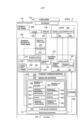
[0012] A Figura 1 é uma ilustração de um ambiente de fabricação na forma de um diagrama de bloco de acordo com uma modalidade ilustrativa;[0012] Figure 1 is an illustration of a manufacturing environment in the form of a block diagram according to an illustrative embodiment;
[0013] A Figura 2 é uma ilustração de um conjunto de fuselagem na forma de um diagrama de bloco de acordo com uma modalidade ilustrativa;[0013] Figure 2 is an illustration of a fuselage assembly in the form of a block diagram according to an illustrative embodiment;
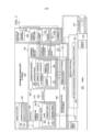
[0014] A Figura 3 é uma ilustração de uma pluralidade de sistemas móveis de um sistema de fabricação flexível dentro de um ambiente de fabricação na forma de um diagrama de bloco de acordo com uma modalidade ilustrativa;[0014] Figure 3 is an illustration of a plurality of mobile systems of a flexible manufacturing system within a manufacturing environment in the form of a block diagram according to an illustrative embodiment;
[0015] A Figura 4 é uma ilustração uma pluralidade de plataformas móveis na forma de um diagrama de bloco de acordo com uma modalidade ilustrativa;[0015] Figure 4 is an illustration of a plurality of mobile platforms in the form of a block diagram according to an illustrative embodiment;
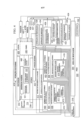
[0016] A Figura 5 é uma ilustração de um fluxo de um número de utilitário por uma rede de utilitário distribuída na forma de um diagrama de bloco de acordo com uma modalidade ilustrativa;[0016] Figure 5 is an illustration of a flow of a utility number through a distributed utility network in the form of a block diagram according to an illustrative embodiment;
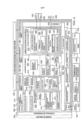
[0017] A Figura 6 é uma ilustração de um sistema de berço na forma de um diagrama de bloco de acordo com uma modalidade ilustrativa;[0017] Figure 6 is an illustration of a cradle system in the form of a block diagram according to an illustrative embodiment;
[0018] A Figura 7 é uma ilustração de uma vista isométrica de um ambiente de fabricação de acordo com uma modalidade ilustrativa;[0018] Figure 7 is an illustration of an isometric view of a manufacturing environment according to an illustrative embodiment;
[0019] A Figura 8 é uma ilustração de uma primeira torre acoplada com um acessório de utilitário de acordo com uma modalidade ilustrativa;[0019] Figure 8 is an illustration of a first tower coupled with a utility accessory according to an illustrative embodiment;
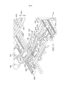
[0020] A Figura 9 é uma ilustração de uma vista isométrica de um sistema de berço de acordo com uma modalidade ilustrativa;[0020] Figure 9 is an illustration of an isometric view of a cradle system according to an illustrative embodiment;
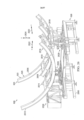
[0021] A Figura 10 é uma ilustração de uma vista isométrica de um acessório de conjunto formado usando um sistema de berço e acoplado com uma primeira torre de acordo com uma modalidade ilustrativa;[0021] Figure 10 is an illustration of an isometric view of a set accessory formed using a cradle system and coupled with a first tower according to an illustrative embodiment;
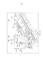
[0022] A Figura 11 é uma ilustração de uma vista isométrica de um estágio no processo de montagem para construir um conjunto de fuselagem que está sendo suportado por um acessório de conjunto de acordo com uma modalidade ilustrativa;[0022] Figure 11 is an illustration of an isometric view of a stage in the assembly process for building a fuselage assembly being supported by an assembly fitting according to an illustrative embodiment;
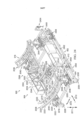
[0023] A Figura 12 é uma ilustração de uma vista isométrica de outro estágio no processo de montagem para construir um conjunto de fuselagem sendo suportado por um acessório de conjunto de acordo com uma modalidade ilustrativa;[0023] Figure 12 is an illustration of an isometric view of another stage in the assembly process for building a fuselage assembly being supported by an assembly fitting according to an illustrative embodiment;
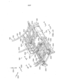
[0024] A Figura 13 é uma ilustração de uma vista isométrica de outro estágio no processo de montagem para construir um conjunto de fuselagem sendo suportado por um acessório de conjunto de acordo com uma modalidade ilustrativa;[0024] Figure 13 is an illustration of an isometric view of another stage in the assembly process for building a fuselage assembly being supported by an assembly fitting according to an illustrative embodiment;
[0025] A Figura 14 é uma ilustração de uma vista isométrica de outro estágio no processo de montagem para construir um conjunto de fuselagem de acordo com uma modalidade ilustrativa;[0025] Figure 14 is an illustration of an isometric view of another stage in the assembly process for constructing a fuselage assembly according to an illustrative embodiment;
[0026] A Figura 15 é uma ilustração de uma vista isométrica de uma segunda torre acoplada com um acessório de utilitário e um acessório de conjunto que suporta um conjunto de fuselagem de acordo com uma modalidade ilustrativa;[0026] Figure 15 is an illustration of an isometric view of a second turret coupled with a utility accessory and an assembly accessory supporting a fuselage assembly according to an illustrative embodiment;
[0027] A Figura 16 é uma ilustração de uma vista de recorte isométrica de uma pluralidade de plataformas móveis realizando processos de fixação dentro de um interior de um conjunto de fuselagem de acordo com uma modalidade ilustrativa;[0027] Figure 16 is an illustration of an isometric cutaway view of a plurality of mobile platforms performing attachment processes within an interior of a fuselage assembly according to an illustrative embodiment;
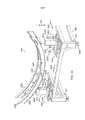
[0028] A Figura 17 é uma ilustração de uma vista de seção transversal de um sistema de fabricação flexível que realiza operações em um conjunto de fuselagem de acordo com uma modalidade ilustrativa;[0028] Figure 17 is an illustration of a cross-sectional view of a flexible manufacturing system that performs operations on a fuselage assembly according to an illustrative embodiment;
[0029] A Figura 18 é uma ilustração de uma vista isométrica de uma fuselagem completamente montada de acordo com uma modalidade ilustrativa;[0029] Figure 18 is an illustration of an isometric view of a fully assembled fuselage according to an illustrative embodiment;
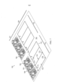
[0030] A Figura 19 é uma ilustração de uma vista isométrica dos conjuntos de fuselagem sendo construídos dentro de um ambiente de fabricação de acordo com uma modalidade ilustrativa;[0030] Figure 19 is an illustration of an isometric view of fuselage assemblies being constructed within a manufacturing environment in accordance with an illustrative embodiment;
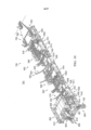
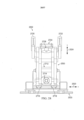
[0031] A Figura 20 é uma ilustração de uma vista isométrica de um acessório de berço de acordo com uma modalidade ilustrativa;[0031] Figure 20 is an illustration of an isometric view of a crib accessory according to an illustrative embodiment;
[0032] A Figura 21 é uma ilustração de uma vista isométrica alargada de um membro de retenção e um sistema de movimento de acordo com uma modalidade ilustrativa;[0032] Figure 21 is an illustration of an enlarged isometric view of a retaining member and a movement system according to an illustrative embodiment;
[0033] A Figura 22 é uma ilustração de uma vista isométrica alargada da estrutura de retenção, um sistema de movimento, e um sistema de movimento de acordo com uma modalidade ilustrativa;[0033] Figure 22 is an illustration of an enlarged isometric view of the retention structure, a movement system, and a movement system according to an illustrative embodiment;
[0034] A Figura 23 é uma ilustração de uma vista isométrica alargada da estrutura de retenção e um sistema de movimento de acordo com uma modalidade ilustrativa;[0034] Figure 23 is an illustration of an enlarged isometric view of the retention structure and a movement system according to an illustrative embodiment;
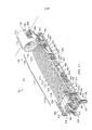
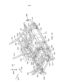
[0035] A Figura 24 é uma ilustração de uma vista isométrica de um acessório de berço com uma unidade de utilitário associada com o acessório de berço de acordo com uma modalidade ilustrativa;[0035] Figure 24 is an illustration of an isometric view of a cradle accessory with a utility unit associated with the cradle accessory according to an illustrative embodiment;
[0036] A Figura 25 é uma ilustração de uma vista isométrica alargada de um acessório de berço de acordo com uma modalidade ilustrativa;[0036] Figure 25 is an illustration of an enlarged isometric view of a crib accessory according to an illustrative embodiment;
[0037] A Figura 26 é uma ilustração de uma vista isométrica alargada da estrutura de retenção de acordo com uma modalidade ilustrativa;[0037] Figure 26 is an illustration of an enlarged isometric view of the retaining structure according to an illustrative embodiment;
[0038] A Figura 27 é uma ilustração de uma vista isométrica alargada da estrutura de retenção de acordo com uma modalidade ilustrativa;[0038] Figure 27 is an illustration of an enlarged isometric view of the retaining structure according to an illustrative embodiment;
[0039] A Figura 28 é uma ilustração de uma vista lateral da estrutura de retenção e um sistema de movimento de acordo com uma modalidade ilustrativa;[0039] Figure 28 is an illustration of a side view of the retention structure and a movement system according to an illustrative embodiment;
[0040] A Figura 29 é uma ilustração de uma vista frontal da estrutura de retenção com um sistema de movimento e outro sistema de movimento de acordo com uma modalidade ilustrativa;[0040] Figure 29 is an illustration of a front view of the retention structure with a movement system and another movement system according to an illustrative embodiment;
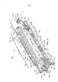
[0041] A Figura 30 é uma ilustração de uma vista isométrica de um acessório de berço com uma unidade de utilitário associada com um acessório de berço de acordo com uma modalidade ilustrativa;[0041] Figure 30 is an illustration of an isometric view of a cradle accessory with a utility unit associated with a cradle accessory according to an illustrative embodiment;
[0042] A Figura 31 é uma ilustração de uma vista isométrica alargada de um acessório de berço de acordo com uma modalidade ilustrativa;A Figura 32 é uma ilustração de uma vista isométrica de um acessório de berço com uma unidade de utilitário associada com um acessório de berço de acordo com uma modalidade ilustrativa;[0042] Figure 31 is an illustration of an enlarged isometric view of a crib accessory according to an illustrative embodiment; Figure 32 is an illustration of an isometric view of a crib accessory with a utility unit associated with an accessory cradle according to an illustrative modality;
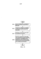
[0043] A Figura 33 é uma ilustração de um processo para configurar um acessório de conjunto na forma de um fluxograma de acordo com uma modalidade ilustrativa;[0043] Figure 33 is an illustration of a process for configuring a set accessory in the form of a flowchart according to an illustrative embodiment;
[0044] A Figura 34 é uma ilustração de um processo para configurar um acessório de conjunto na forma de um fluxograma de acordo com uma modalidade ilustrativa;[0044] Figure 34 is an illustration of a process for configuring a set accessory in the form of a flowchart according to an illustrative embodiment;
[0045] A Figura 35 é uma ilustração de um processo para ajustar a estrutura de retenção de um acessório de berço na forma de um fluxograma de acordo com uma modalidade ilustrativa;[0045] Figure 35 is an illustration of a process for adjusting the retention structure of a crib accessory in the form of a flowchart according to an illustrative embodiment;
[0046] A Figura 36 é uma ilustração do ajuste de uma estrutura de retenção ajustável na forma de um fluxograma de acordo com uma modalidade ilustrativa;[0046] Figure 36 is an illustration of the adjustment of an adjustable retention structure in the form of a flowchart according to an illustrative embodiment;
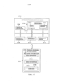
[0047] A Figura 37 é uma ilustração de um sistema de processamento de dados na forma de um diagrama de bloco de acordo com uma modalidade ilustrativa;[0047] Figure 37 is an illustration of a data processing system in the form of a block diagram according to an illustrative embodiment;
[0048] A Figura 38 é uma ilustração de um método de fabricação e serviço de aeronave na forma de um diagrama de bloco de acordo com uma modalidade ilustrativa; e[0048] Figure 38 is an illustration of an aircraft manufacturing and service method in the form of a block diagram according to an illustrative embodiment; It is
[0049] A Figura 39 é uma ilustração de uma aeronave na forma de um diagrama de bloco em que uma modalidade ilustrativa pode ser implementada.[0049] Figure 39 is an illustration of an aircraft in the form of a block diagram in which an illustrative embodiment can be implemented.
[0050] As modalidades ilustrativas reconhecem e levam em conta diferentes considerações. Por exemplo, as modalidades ilustrativas reconhecem e levam em conta que pode ser desejável automatizar o processo de construir um conjunto de fuselagem para uma aeronave. Automatizando o processo de construir um conjunto de fuselagem para uma aeronave pode aprimorar eficiência de construção, aprimorar a qualidade de construção, e reduzir custos associados com a construção do conjunto de fuselagem. As modalidades ilustrativas também reconhecem e levam em conta que automatizando o processo de construir um conjunto de fuselagem pode aprimorar a acurácia e a precisão com a qual operações de montagem são realizadas, garantindo desta forma conformidade aprimorada com requisitos de linha de molde externo (OML) e requisitos de linha de molde interno (IML) para o conjunto de fuselagem.[0050] The illustrative modalities recognize and take into account different considerations. For example, the illustrative embodiments recognize and take into account that it may be desirable to automate the process of building a fuselage assembly for an aircraft. Automating the process of building an airframe assembly for an aircraft can improve construction efficiency, improve build quality, and reduce costs associated with fuselage assembly construction. The illustrative embodiments also recognize and take into account that automating the process of building an airframe assembly can improve the accuracy and precision with which assembly operations are carried out, thereby ensuring improved compliance with external mold line (OML) requirements. and internal mold line (IML) requirements for the fuselage assembly.
[0051] Adicionalmente, as modalidades ilustrativas reconhecem e levam em conta que automatizando o processo usado para construir um conjunto de fuselagem para uma aeronave pode reduzir de maneira significativa a quantidade de tempo necessário para o ciclo de construção. Por exemplo, sem limitação, automatizando operações de fixação pode-se reduzir e, em alguns casos, eliminar, a necessidade que operadores humanos realizem estas operações de fixação bem como outros tipos de operações de montagem.[0051] Additionally, the illustrative embodiments recognize and take into account that automating the process used to build a fuselage assembly for an aircraft can significantly reduce the amount of time required for the construction cycle. For example, without limitation, automating fixture operations can reduce, and in some cases eliminate, the need for human operators to perform these fixture operations as well as other types of assembly operations.
[0052] Adicionalmente, este tipo de automação do processo para construir um conjunto de fuselagem para uma aeronave pode dar menos trabalho, consumir menos tempo, ser ergonomicamente menos desafiador e mais barato do que realizar este processo de maneira primariamente manual. Trabalho manual reduzido pode ter um benefício desejado para o trabalhador humano. Adicionalmente, automatizando o processo de conjunto de fuselagem pode-se permitir que conjuntos de fuselagem sejam construídos em fábricas e instalações de montagem adequadas em taxas de montagem desejadas e custos de montagem desejados.[0052] Additionally, this type of automation of the process to build a fuselage assembly for an aircraft can be less labor intensive, less time consuming, ergonomically less challenging, and cheaper than performing this process primarily manually. Reduced manual labor may have a desired benefit for the human worker. Additionally, automating the airframe assembly process can allow airframe assemblies to be built in suitable factories and assembly facilities at desired assembly rates and desired assembly costs.
[0053] As modalidades ilustrativas também reconhecem e levam em conta que pode ser desejável usar equipamento que pode ser acionado e operado de maneira autônoma para automatizar o processo de construir um conjunto de fuselagem. Em particular, pode ser desejável ter um sistema de fabricação flexível autônomo compreendido de sistemas móveis que podem ser acionados de maneira autônoma por um piso de fábrica, posicionados de maneira autônoma com relação ao piso de fábrica como necessário para construir o conjunto de fuselagem, operados de maneira autônoma para construir o conjunto de fuselagem, e então afastados de maneira autônoma quando a construção do conjunto de fuselagem foi completada.[0053] The illustrative embodiments also recognize and take into account that it may be desirable to use equipment that can be triggered and operated autonomously to automate the process of constructing a fuselage assembly. In particular, it may be desirable to have a self-contained flexible manufacturing system comprised of mobile systems that can be autonomously driven by a factory floor, autonomously positioned relative to the factory floor as needed to build the fuselage assembly, operated autonomously to build the fuselage assembly, and then autonomously moved away when construction of the fuselage assembly was completed.
[0054] Como usado aqui, realizar qualquer operação, ação ou etapa de maneira autônoma pode significar realizar aquela operação substancialmente sem qualquer entrada humana. Por exemplo, sem limitação, uma plataforma que pode ser acionada de maneira autônoma é uma plataforma que pode ser acionada substancialmente independentemente de qualquer entrada humana. Desta maneira, uma plataforma acionável de maneira autônoma pode ser uma plataforma que é capaz de acionar ou ser acionada substancialmente independentemente de entrada humana.[0054] As used herein, performing any operation, action, or step autonomously may mean performing that operation substantially without any human input. For example, without limitation, an autonomously operable platform is a platform that can actuate substantially independently of any human input. In this way, an autonomously actuatable platform can be a platform that is capable of actuating or being actuated substantially independently of human input.
[0055] Assim, as modalidades ilustrativas proveem um método, aparelho, e o sistema para construir um conjunto de fuselagem para uma aeronave. Em particular, as modalidades ilustrativas proveem um sistema de fabricação flexível autônomo que automatiza a maioria, se não todo, do processo de construir um conjunto de fuselagem. Por exemplo, sem limitação, o sistema de fabricação flexível autônomo pode automatizar o processo de instalação de fixadores para unir painéis de pele de fuselagem e uma fuselagem estrutura de berço juntos para construir o conjunto de fuselagem.[0055] Thus, the illustrative embodiments provide a method, apparatus, and system for constructing a fuselage assembly for an aircraft. In particular, the illustrative embodiments provide an autonomous flexible fabrication system that automates most, if not all, of the process of building a fuselage assembly. For example, without limitation, the self-contained flexible fabrication system can automate the process of installing fasteners to join fuselage skin panels and a fuselage cradle frame together to build the fuselage assembly.
[0056] No entanto, as modalidades ilustrativas reconhecem e levam em conta que automatizando o processo para construir um conjunto de fuselagem usando um sistema de fabricação flexível autônomo pode apresentar desafios técnicos únicos que necessitam de soluções técnicas únicas. Por exemplo, as modalidades ilustrativas reconhecem e levam em conta que pode ser desejável prover utilitários para todos os vários sistemas dentro do sistema de fabricação flexível autônomo. Em particular, pode ser desejável prover estes utilitários de uma maneira que não vai interromper ou atrasar o processo de construir o conjunto de fuselagem ou restringir o movimento de vários sistemas móveis dentro do sistema de fabricação flexível autônomo por um piso de fábrica.[0056] However, the illustrative embodiments recognize and take into account that automating the process to build a fuselage assembly using an autonomous flexible fabrication system can present unique technical challenges that necessitate unique technical solutions. For example, the illustrative embodiments recognize and take into account that it may be desirable to provide utilities for all of the various systems within the autonomous flexible manufacturing system. In particular, it may be desirable to provide these utilities in a manner that will not interrupt or delay the process of building the fuselage assembly or restrict the movement of various mobile systems within the self-contained flexible fabrication system across a factory floor.
[0057] Por exemplo, sem limitação, pode ser desejável prover uma série de utilitário, tais como energia, comunicações e ar, para o sistema de fabricação flexível autônomo usando uma infraestrutura que inclui apenas uma única conexão direta com cada de uma série de fontes de utilitário provendo a série de utilitário. Estas conexões diretas podem estar acima do solo, no solo ou ser incorporadas. Estas conexões diretas podem ser estabelecidas usando, por exemplo, sem limitação, um acessório de utilitário. Assim, a infraestrutura pode incluir um acessório de utilitário que provê uma conexão direta com cada da série de fontes de utilitário e uma área de montagem com um espaço de piso suficientemente grande para permitir que vários sistemas de um sistema de fabricação flexível autônomo sejam acoplados com o acessório de utilitário e entre si em série. Desta maneira, a série de utilitário pode fluir da série de fontes de utilitário para o acessório de utilitário e então a jusante para os vários sistemas do sistema de fabricação flexível autônomo dentro da área de montagem.[0057] For example, without limitation, it may be desirable to provide a number of utilities, such as power, communications and air, to the autonomous flexible manufacturing system using an infrastructure that includes only a single direct connection to each of a number of sources of utility supplying the utility series. These direct connections can be above ground, in the ground or built in. These direct connections may be established using, for example, without limitation, a utility accessory. Thus, the infrastructure can include a utility fixture that provides a direct connection to each of the utility source series and a mounting area with a floor space large enough to allow multiple systems of a self-contained flexible manufacturing system to be coupled with each other. the utility accessory and each other in series. In this way, the utility series can flow from the utility source series to the utility accessory and then downstream to the various systems of the self-contained flexible manufacturing system within the assembly area.
[0058] Assim, as modalidades ilustrativas proveem uma rede de utilitário distribuída que pode ser usada para prover utilitários para os vários sistemas do sistema de fabricação flexível autônomo. A rede de utilitário distribuída pode prover estes utilitários de uma maneira que não restringe ou impede movimento dos vários sistemas móveis do sistema de fabricação flexível autônomo. Os diferentes sistemas móveis do sistema de fabricação flexível autônomo podem ser acoplados de maneira autônoma entre si para criar esta rede de utilitário distribuída.[0058] Thus, the illustrative embodiments provide a distributed utility network that can be used to provide utilities for the various systems of the autonomous flexible manufacturing system. The distributed utility network can provide these utilities in a manner that does not restrict or impede movement of the various mobile systems of the autonomous flexible manufacturing system. The different mobile systems of the autonomous flexible manufacturing system can be autonomously coupled together to create this distributed utility network.
[0059] Adicionalmente, as modalidades ilustrativas reconhecem e levam em conta que pode ser desejável ter um aparelho e método para suportar um conjunto de fuselagem durante a construção do conjunto de fuselagem de uma maneira que satisfaz tolerâncias desejadas. Em particular, pode ser desejável ter um método e aparelho para suportar um conjunto de fuselagem que permite que o conjunto de fuselagem seja construído dentro de tolerâncias selecionadas de requisitos de linha de molde externo e requisitos de linha de molde interno para o conjunto de fuselagem. Assim, as modalidades ilustrativas proveem um sistema de berço que podem ser usados para formar um acessório de conjunto para suportar e reter um conjunto de fuselagem.[0059] Additionally, the illustrative embodiments recognize and take into account that it may be desirable to have an apparatus and method for supporting a fuselage assembly during construction of the fuselage assembly in a manner that satisfies desired tolerances. In particular, it may be desirable to have a method and apparatus for supporting a fuselage assembly that allows the fuselage assembly to be constructed within selected tolerances of external mold line requirements and internal mold line requirements for the fuselage assembly. Thus, the illustrative embodiments provide a cradle system that can be used to form an assembly fixture for supporting and retaining a fuselage assembly.
[0060] Em referência agora às figuras e, em particular, com referência às Figuras 1 a 6, ilustrações de um ambiente de fabricação são representadas na forma de diagramas de bloco de acordo com uma modalidade ilustrativa. Em particular, nas figuras 1 a 6, um conjunto de fuselagem, um sistema de fabricação flexível, os vários sistemas dentro do sistema de fabricação flexível que podem ser usados para construir o conjunto de fuselagem, e uma rede de utilitário distribuída são descritos.[0060] With reference now to the figures and, in particular, with reference to Figures 1 to 6, illustrations of a manufacturing environment are represented in the form of block diagrams according to an illustrative embodiment. In particular, in Figures 1 to 6, a fuselage assembly, a flexible fabrication system, the various systems within the flexible fabrication system that can be used to build the fuselage assembly, and a distributed utility network are depicted.
[0061] Se voltando agora à Figura 1, uma ilustração de um ambiente de fabricação é representada na forma de um diagrama de bloco de acordo com uma modalidade ilustrativa. Neste exemplo ilustrativo, ambiente de fabricação 100 pode ser um exemplo de um ambiente em que pelo menos uma porção da fuselagem 102 pode ser fabricada para a aeronave 104.[0061] Turning now to Figure 1, an illustration of a manufacturing environment is represented in the form of a block diagram according to an illustrative embodiment. In this illustrative example,
[0062] O ambiente de fabricação 100 pode tomar um número de diferentes formas. Por exemplo, sem limitação, ambiente de fabricação 100 pode tomar a forma de uma fábrica, uma instalação de fabricação, uma área de fábrica aberta, uma área de fabricação fechada, uma plataforma fora de costa, ou alguns outros tipos de ambiente de fabricação 100 adequado para ligar pelo menos uma porção da fuselagem 102.[0062] The
[0063] A fuselagem 102 pode ser construída usando o processo de fabricação 108. O sistema de fabricação flexível 106 pode ser usado para implementar pelo menos uma porção do processo de fabricação 108. Em um exemplo ilustrativo, o processo de fabricação 108 pode ser substancialmente automatizado usando o sistema de fabricação flexível 106. Em outros exemplos ilustrativos, apenas um ou mais estágios do processo de fabricação 108 podem ser substancialmente automatizados.[0063] The
[0064] O sistema de fabricação flexível 106 pode ser configurado para realizar pelo menos uma porção do processo de fabricação 108 de maneira autônoma. Desta maneira, o sistema de fabricação flexível 106 pode ser referido como o sistema de fabricação flexível autônomo 112. Em outros exemplos ilustrativos, o sistema de fabricação flexível 106 pode ser referido como um sistema de fabricação flexível automatizado.[0064] The
[0065] Como representado, o processo de fabricação 108 pode incluir o processo de montagem 110 para construir o conjunto de fuselagem 114. O sistema de fabricação flexível 106 pode ser configurado para realizar pelo menos uma porção do processo de montagem 110 de maneira autônoma.[0065] As depicted, the fabrication process 108 can include the
[0066] O conjunto de fuselagem 114 pode ser a fuselagem 102 em qualquer estágio durante o processo de fabricação 108 antes do fim do processo de fabricação 108. Em alguns casos, o conjunto de fuselagem 114 pode ser usado para se referir a uma fuselagem parcialmente montada 102. Dependendo da implementação, um ou mais outros componentes podem precisar ser anexados ao conjunto de fuselagem 114 para completar completamente a montagem da fuselagem 102. Em outros casos, o conjunto de fuselagem 114 pode ser usado para se referir à fuselagem completamente montada 102. O sistema de fabricação flexível 106 pode construir o conjunto de fuselagem 114 até o ponto necessário para mover o conjunto de fuselagem 114 para um próximo estágio no processo de fabricação para construir aeronave 104. Em alguns casos, pelo menos uma porção do sistema de fabricação flexível 106 pode ser usada em um ou mais estágios posteriores no processo de fabricação para construir aeronave 104.[0066] The
[0067] Em um exemplo ilustrativo, o conjunto de fuselagem 114 pode ser um conjunto para formar uma seção particular da fuselagem 102. Como um exemplo, o conjunto de fuselagem 114 pode tomar a forma de conjunto de fuselagem traseira 116 para formar uma seção de popa da fuselagem 102. Em outro exemplo, o conjunto de fuselagem 114 pode tomar a forma de conjunto de fuselagem dianteiro 117 para formar uma seção dianteira da fuselagem 102. Em mais um exemplo, o conjunto de fuselagem 114 pode tomar a forma de conjunto de fuselagem médio 118 para formar uma seção central da fuselagem 102 ou alguma outra seção média da fuselagem 102 entre as seções de popa e dianteira da fuselagem 102.[0067] In an illustrative example, the
[0068] Como representado, o conjunto de fuselagem 114 pode incluir a pluralidade de painéis 120 e a estrutura de berço 121. A estrutura de berço 121 pode ser compreendida de pluralidade de membros 122. A pluralidade de membros 122 pode ser usada tanto para suportar a pluralidade de painéis 120 quanto para conectar a pluralidade de painéis 120 entre si. A estrutura de berço 121 pode ajudar a prover resistência, rigidez e berço de carga para o conjunto de fuselagem 114.[0068] As depicted, the
[0069] A pluralidade de membros 122 pode ser associada com a pluralidade de painéis 120. Como usado aqui, quando um componente ou guVtwVwtc guVá “cuuqekcfc” eqo qwVtq eqorqpgpVg qw guVtwVwtc. c cuuqekc>«q fi uma associação física nos exemplos representados.[0069] The plurality of
[0070] Por exemplo, um primeiro componente, tal como um da pluralidade de membros 122, pode ser considerado como associado com um segundo componente, tal como um da pluralidade de painéis 120, sendo pelo menos um dos presos ao segundo componente, ligado ao segundo componente, montado ao segundo componente, anexado ao componente, acoplado com o componente, soldado ao segundo componente, fixado ao segundo componente, aderido ao segundo componente, colado ao segundo componente, ou conectado com o segundo componente de alguma outra maneira adequada. O primeiro componente também pode ser conectado com o segundo componente usando um ou mais outros componentes. Por exemplo, o primeiro componente pode ser conectado com o segundo componente usando um terceiro componente. Adicionalmente, o primeiro componente pode ser considerado como associado com o segundo componente sendo formado como parte do segundo componente, uma extensão do segundo componente, ou ambos. Em outro exemplo, o primeiro componente pode ser considerado parte do segundo componente sendo curado em conjunto com o segundo componente.[0070] For example, a first component, such as one of the plurality of
[0071] Eqoq wucfq cswk. a htaug “rglq ogpqu wo fg.” swcpfq wucfc com uma lista de itens, quer dizer diferentes combinações de um ou mais dos itens listados podem ser usadas e apenas um dos itens na lista pode ser necessário. O item pode ser um objeto, coisa, ação, processo ou categoria rctVkewncto Go qwttcu ralcxtcu, “rgnq ogpqu wo fg” swgt fkzgt swcnswgt combinação de itens ou número de itens podem ser usados da lista, mas nem todos os itens na lista podem ser necessários.[0071] Eqoq wucfq cswk. a htaug “rglq ogpqu wo fg.” swcpfq wucfc with a list of items, ie different combinations of one or more of the listed items can be used and only one of the items in the list may be needed. The item can be an object, thing, action, process or category rctVkewncto Go qwttcu ralcxtcu, “rgnq ogpqu wo fg” swgt fkzgt swcnswgt combination of items or number of items can be used from the list, but not all items in the list can be used needed.
[0072] Rqt gzgornq. “rgnq ogpqu wo fg kvgo C. kvgo D. g kvgo E” qw “rgnq ogpqu wo fg kvgo C. kvgo D. qw kvgo E” rqfg ukipkhkect kvgo C= kvgo C e item B; item B; item A, item B, e item C; ou item B e item C. Em alguns casos, “rgnq ogpqu wo fg kvgo C. kvgo D. g kvgo E” rqfg ukipkhkect. rqt exemplo, sem limitação, dois do item A, um do item B, e dez do item C; quatro do item B e sete do item C; ou alguma outra combinação adequada.[0072] Rqt gzgornq. “rgnq ogpqu wo fg kvgo C. kvgo D. g kvgo E” qw “rgnq ogpqu wo fg kvgo C. kvgo D. qw kvgo E” rqfg ukipkhkect kvgo C= kvgo C and item B; item B; item A, item B, and item C; or item B and item C. In some cases, “rgnq ogpqu wo fg kvgo C. kvgo D. g kvgo E” rqfg ukipkhkect. rqt example, without limitation, two of item A, one of item B, and ten of item C; four from item B and seven from item C; or some other suitable combination.
[0073] Nestes exemplos ilustrativos, um membro da pluralidade de membros 122 pode ser associada com pelo menos um de pluralidade de painéis 120 em um número de diferentes modos. Por exemplo, sem limitação, um membro da pluralidade de membros 122 pode ser anexado diretamente com um único painel, anexado a dois ou mais painéis, anexado ao outro membro que é diretamente anexado com pelo menos um painel, anexado com pelo menos um membro que é diretamente ou indiretamente anexado com pelo menos um painel, ou associada com pelo menos um de pluralidade de painéis 120 de algum outro modo.[0073] In these illustrative examples, one member of the plurality of
[0074] Em um exemplo ilustrativo, substancialmente todos ou todos da pluralidade de membros 122 pode ser associada com a pluralidade de painéis 120 antes do início do processo de montagem 110 para construir o conjunto de fuselagem 114. Por exemplo, uma correspondente porção da pluralidade de membros 122 pode ser associada com cada painel da pluralidade de painéis 120 antes da pluralidade de painéis 120 sendo unidos entre si através do processo de montagem 110.[0074] In an illustrative example, substantially all or all of the plurality of
[0075] Em outro exemplo ilustrativo, apenas uma primeira porção da pluralidade de membros 122 pode ser associada com a pluralidade de painéis 120 antes do início do processo de montagem 110. Processo de montagem 110 pode incluir anexar uma porção remanescente da pluralidade de membros 122 com a pluralidade de painéis 120 para pelo menos um de prover berço para pluralidade de painéis 120 ou conectar a pluralidade de painéis 120. A primeira porção da pluralidade de membros 122 anexada à pluralidade de painéis 120 antes de processo de montagem 110 e a porção remanescente da pluralidade de membros 122 anexada à pluralidade de painéis 120 durante o processo de montagem 110 juntos podem formar a estrutura de berço 121.[0075] In another illustrative example, only a first portion of the plurality of
[0076] Em mais um exemplo ilustrativo, todos da pluralidade de membros 122 pode ser associada com a pluralidade de painéis 120 durante o processo de montagem 110. Por exemplo, cada um da pluralidade de painéis 342 rqfg ugt “rgncfq” ugo swckuswgt ogodtqu cpgzcfqu eqo qw fg qwVtc forma associados com o painel antes de processo de montagem 110. Durante o processo de montagem 110, a pluralidade de membros 122 então pode ser associada com a pluralidade de painéis 120.[0076] In yet another illustrative example, all of the plurality of
[0077] Desta maneira, a estrutura de berço 121 para o conjunto de fuselagem 114 pode ser construído em um número de diferentes modos. O conjunto de fuselagem 114 compreendendo a pluralidade de painéis 120 e a estrutura de berço 121 é descrita em maior detalhe na Figura 2 abaixo.[0077] In this way, the
[0078] A construção do conjunto de fuselagem 114 pode incluir unir a pluralidade de painéis 120. A união da pluralidade de painéis 120 pode ser realizada em um número de diferentes modos. Dependendo da implementação, a união da pluralidade de painéis 120 pode incluir unir um ou mais da pluralidade de membros 122 com um ou mais da pluralidade de painéis 120 ou para outros membros da pluralidade de membros 122.[0078] The construction of the
[0079] Em particular, a união da pluralidade de painéis 120 pode incluir unir pelo menos um painel a pelo menos um outro painel, unindo pelo menos um membro com pelo menos um outro membro, ou unindo pelo menos um membro com pelo menos um painel, ou alguma combinação das mesmas. Como um exemplo ilustrativo, unir um primeiro painel e um segundo painel pode incluir pelo menos um dos seguintes: fixar o primeiro painel diretamente com o segundo painel, unir um primeiro membro associado com o primeiro painel com um segundo membro associado com o segundo painel, unir a membro associado com o primeiro painel diretamente com o segundo painel, unir um membro associado tanto com o primeiro painel quanto com o segundo painel para outro membro, unir um membro selecionado tanto com o primeiro painel quanto com o segundo painel, ou alguns outros tipos de operação de união.[0079] In particular, joining the plurality of
[0080] O processo de montagem 110 pode incluir operações 124 que podem ser realizadas para unir a pluralidade de painéis 120 para construir o conjunto de fuselagem 114. Neste exemplo ilustrativo, o sistema de fabricação flexível 106 pode ser usado para realizar pelo menos uma porção de operações 124 de maneira autônoma.[0080] The
[0081] As operações 124 podem incluir, por exemplo, entre outras, as operações de conexão temporárias 125, as operações de perfuração 126, as operações de inserção de fixador 128, as operações de instalação de fixador 130, as operações de inspeção 132, outros tipos de operações de montagem, ou alguma combinação das mesmas. As operações de conexão temporárias 125 podem ser realizadas para conectar temporariamente a pluralidade de painéis 120. Por exemplo, sem limitação, as operações de conexão temporárias 125 podem incluir aderir temporariamente a pluralidade de painéis 120 juntos usando fixadores de aderência.[0081]
[0082] As operações de perfuração 126 podem incluir orifícios de perfuração através de um ou mais da pluralidade de painéis 120 e, em alguns casos, através de um ou mais da pluralidade de membros 122. As operações de inserção de fixador 128 podem incluir inserir fixadores nos orifícios perfurados pelas operações de perfuração 126.[0082]
[0083] As operações de instalação de fixador 130 podem incluir instalar completamente cada um dos fixadores que foram inseridos nos orifícios. As operações de instalação de fixador 130 podem incluir, por exemplo, sem limitação, as operações de rebitagem, as operações de aparafusamento de encaixe de interferência, outros tipos de operações de instalação de fixador, ou alguma combinação das mesmas. As operações de inspeção 132 pode incluir inspecionar os fixadores completamente instalados. Dependendo da implementação, o sistema de fabricação flexível 106 pode ser usado para realizar qualquer número destes diferentes tipos de operações 124 substancialmente de maneira autônoma.[0083] The
[0084] Como representado, o sistema de fabricação flexível 106 pode incluir a pluralidade de sistemas móveis 134, o sistema de controle 136, e o sistema de utilitário 138. Cada um da pluralidade de sistemas móveis 134 pode ser um sistema móvel acionável. Em alguns casos, cada um da pluralidade de sistemas móveis 134 pode ser um sistema móvel acionável de maneira autônoma. Por exemplo, sem limitação, cada um da pluralidade de sistemas móveis 134 pode incluir um ou mais componentes que podem ser acionados de maneira autônoma dentro do ambiente de fabricação 100 a partir de uma localização para outra localização. A pluralidade de sistemas móveis 134 são descritos em maior detalhe na Figura 3 abaixo.[0084] As depicted, the
[0085] Neste exemplo ilustrativo, o sistema de controle 136 pode ser usado para controlar a operação do sistema de fabricação flexível 106. Por exemplo, sem limitação, o sistema de controle 136 pode ser usado para controlar pluralidade de sistemas móveis 134. Em particular, o sistema de controle 136 pode ser usado para direcionar o movimento de cada um da pluralidade de sistemas móveis 134 dentro do ambiente de fabricação 100. O sistema de controle 136 pode ser pelo menos parcialmente associado com a pluralidade de sistemas móveis 134.[0085] In this illustrative example, the
[0086] Em um exemplo ilustrativo, o sistema de controle 136 pode incluir a série de controladores 140. Como usado aqui, umc “ufitkg fg” kVgpu pode incluir um ou mais itens. Desta maneira, a série de controladores 140 pode incluir um ou mais controladores.[0086] In an illustrative example,
[0087] Cada uma da série de controladores 140 pode ser implementado usando hardware, firmware, software, ou alguma combinação das mesmas. Em um exemplo ilustrativo, a série de controladores 140 pode ser associado com a pluralidade de sistemas móveis 134. Por exemplo, sem limitação, um ou mais das séries de controle 140 podem ser implementados como parte da pluralidade de sistemas móveis 134. Em outros exemplos, uma ou mais das séries de controle 140 podem ser implementados independentemente de pluralidade de sistemas móveis 134.[0087] Each of the 140 series of controllers can be implemented using hardware, firmware, software, or some combination thereof. In an illustrative example, the array of controllers 140 may be associated with the plurality of
[0088] A série de controladores 140 pode gerar comandos 142 para controlar a operação da pluralidade de sistemas móveis 134 do sistema de fabricação flexível 106. A série de controladores 140 pode se comunicar com a pluralidade de sistemas móveis 134 usando pelo menos um de uma ligação de comunicações sem fios, uma ligação de comunicações com fios, uma ligação de comunicações óptica, ou outro tipo de ligação de comunicações. Desta maneira, qualquer número de diferentes tipos de ligações de comunicações pode ser usado para a comunicação com a e entre a série de controladores 140.[0088] The series of controllers 140 can generate
[0089] Nestes exemplos ilustrativos, o sistema de controle 136 pode controlar a operação da pluralidade de sistemas móveis 134 usando dados 141 recebidos a partir do sistema de sensor 133. O sistema de sensor 133 pode ser compreendido de qualquer número de sistemas de sensor individuais, dispositivos de sensor, controladores, outros tipos de componentes, ou combinação dos mesmos. Em um exemplo ilustrativo, o sistema de sensor 133 pode incluir o sistema de rastreamento a laser 135 e o sistema de radar 137. O sistema de rastreamento a laser 135 pode ser compreendido de qualquer número de dispositivos de rastreamento a laser, alvos a laser, ou combinação dos mesmos. O sistema de radar 137 pode ser compreendido de qualquer número de sensores de radar, alvos de radar, ou combinação dos mesmos.[0089] In these illustrative examples, the
[0090] O sistema de sensor 133 pode ser usado para coordenar o movimento e a operação dos vários sistemas móveis na pluralidade de sistemas móveis 134 dentro do ambiente de fabricação 100. Como um exemplo ilustrativo, o sistema de radar 137 pode ser usado para macro- posicionar sistemas móveis, sistemas dentro de sistemas móveis, componentes dentro de sistemas móveis, ou alguma combinação das mesmas. Adicionalmente, o sistema de rastreamento a laser 135 pode ser usado para micro-posicionar sistemas móveis, sistemas dentro de sistemas móveis, componentes dentro de sistemas móveis, ou alguma combinação das mesmas.[0090] The
[0091] A pluralidade de sistemas móveis 134 pode ser usado para formar a rede de utilitário distribuída 144. Dependendo da implementação, um ou mais da pluralidade de sistemas móveis 134 pode formar a rede de utilitário distribuída 144. O número de utilitário 146 pode fluir a partir do número de fontes de utilitário 148 para os vários sistemas móveis da pluralidade de sistemas móveis 134 que compõem a rede de utilitário distribuída 144.[0091] The plurality of
[0092] Neste exemplo ilustrativo, cada um do número de fontes de utilitário 148 pode ser localizado com o ambiente de fabricação 100. Em outros exemplos ilustrativos, um ou mais do número de fontes de utilitário 148 pode ser localizado fora do ambiente de fabricação 100. O correspondente utilitário provido por estas uma ou mais fontes de utilitário então pode ser realizada no ambiente de fabricação 100 usando, por exemplo, sem limitação, um ou mais cabos de utilitário.[0092] In this illustrative example, each of the number of
[0093] Em um exemplo ilustrativo, a rede de utilitário distribuída 144 pode permitir que o número de utilitário 146 flua diretamente a partir do número de fontes de utilitário 148 para um sistema móvel na pluralidade de sistemas móveis 134 por algum número de cabos de utilitário. Este um sistema móvel então pode distribuir o número de utilitário 146 para outros sistemas móveis da pluralidade de sistemas móveis 134 tal que estes outros sistemas móveis não precisam receber diretamente o número de utilitário 146 a partir do número de fontes de utilitário 148.[0093] In an illustrative example, the distributed
[0094] Como representado, a rede de utilitário distribuída 144 pode ser formada usando o sistema de utilitário 138. O sistema de utilitário 138 pode incluir o acessório de utilitário 150. O sistema de utilitário 138 pode ser configurado para se conectar com o número de fontes de utilitário 148 tal que o número de utilitário 146 pode fluir a partir do número de fontes de utilitário 148 para o acessório de utilitário 150. O acessório de utilitário 150 pode estar acima do solo ou no solo, dependendo da implementação. Por exemplo, sem limitação, o acessório de utilitário 150 pode ser incorporado em um piso dentro do ambiente de fabricação 100.[0094] As depicted, distributed
[0095] O acessório de utilitário 150 então pode distribuir o número de utilitário 146 para um ou mais da pluralidade de sistemas móveis 134. Em particular, um acoplamento autônomo de um da pluralidade de sistemas móveis 134 para o acessório de utilitário 150 pode ser seguido por qualquer número de acoplamento autônomos dos sistemas móveis entre si em série para formar a rede de utilitário distribuída 144. O acessório de utilitário 150 pode distribuir o número de utilitário 146 para cada um da pluralidade de sistemas móveis 134 a jusante do acessório de utilitário 150 na série dos acoplamentos autônomos dos sistemas móveis.[0095] The
[0096] Dependendo da implementação, a rede de utilitário distribuída 144 pode ter uma configuração semelhante a cadeia ou uma configuração semelhante a árvore. Em um exemplo ilustrativo, a pluralidade de sistemas móveis 134 pode incluir sistemas móveis A, B, C, e D (não mostrado na figura) com o sistema móvel A de maneira autônoma acoplado com o acessório de utilitário 150 e os sistemas móveis B, C, e D acoplados de maneira autônoma com o sistema móvel A e entre si em série. Um exemplo de uma configuração semelhante a cadeia para a rede de utilitário distribuída 144 pode incluir o número de utilitário 146 fluindo a partir do número de fontes de utilitário 148 por algum número de cabos de utilitário para o acessório de utilitário 150, a partir do acessório de utilitário 150 para o sistema móvel A, a partir do sistema móvel A para o sistema móvel B, a partir do sistema móvel B para o sistema móvel C, e a partir do sistema móvel C para o sistema móvel D. Um exemplo de uma configuração semelhante a árvore para a rede de utilitário distribuída 144 pode incluir o número de utilitário 146 fluindo a partir do número de fontes de utilitário 148 por algum número de cabos de utilitário para o acessório de utilitário 150, a partir do acessório de utilitário 150 para o sistema móvel A, a partir do sistema móvel A tanto para o sistema móvel B quanto para o sistema móvel C, e a partir do sistema móvel C para o sistema móvel D. Um exemplo de uma maneira em que a rede de utilitário distribuída 144 pode ser implementada usando a pluralidade de sistemas móveis 134 é descrita em maior detalhe na Figura 5 abaixo.[0096] Depending on the implementation, the distributed
[0097] Em alguns exemplos ilustrativos, múltiplos sistemas de fabricação flexíveis podem ser usados para construir múltiplos conjuntos de fuselagem concorrentemente. Por exemplo, o sistema de fabricação flexível 106 pode ser um primeiro sistema de fabricação flexível de muitos sistemas de fabricação flexíveis.[0097] In some illustrative examples, multiple flexible fabrication systems can be used to build multiple airframe assemblies concurrently. For example,
[0098] Em um exemplo ilustrativo, o sistema de fabricação flexível 106, o segundo sistema de fabricação flexível 152, e o terceiro sistema de fabricação flexível 154 pode ser usado para construir conjunto de fuselagem traseira 116, o conjunto de fuselagem médio 118, e o conjunto de fuselagem dianteiro 117, respectivamente. O conjunto de fuselagem traseira 116, o conjunto de fuselagem médio 118, e o conjunto de fuselagem dianteiro 117 então podem ser unidos para formar uma fuselagem completamente montada 102. Desta maneira, neste exemplo, o sistema de fabricação flexível 106, o segundo sistema de fabricação flexível 152, e o terceiro sistema de fabricação flexível 154 juntos podem formar o sistema de fabricação de fuselagem flexível 158.[0098] In an illustrative example, the
[0099] Assim, qualquer número de conjuntos de fuselagem, tal como o conjunto de fuselagem 114, pode ser construído dentro do ambiente de fabricação 100 usando qualquer número de sistemas de fabricação flexíveis implementado de uma maneira similar ao sistema de fabricação flexível 106. Similarmente, qualquer número de fuselagens completas, tal como a fuselagem 102, pode ser construído dentro do ambiente de fabricação 100 usando qualquer número de sistemas de fabricação de fuselagem flexível implementados de uma maneira similar ao sistema de fabricação de fuselagem flexível 158.[0099] Thus, any number of airframe assemblies, such as
[00100] Com referência agora à Figura 2, uma ilustração do conjunto de fuselagem 114 a partir da Figura 1 é representada na forma de um diagrama de bloco de acordo com uma modalidade ilustrativa. Como descrito acima, o conjunto de fuselagem 114 pode incluir a pluralidade de painéis 120 e a estrutura de berço 121. O conjunto de fuselagem 114 pode ser usado para se referir a qualquer estágio na construção do conjunto de fuselagem 114. Por exemplo, o conjunto de fuselagem 114 pode ser usado para se referir a um único um da pluralidade de painéis 120, múltiplos da pluralidade de painéis 120 que foram ou estão sendo unidos, um conjunto de fuselagem parcialmente construído, ou um conjunto de fuselagem completamente construído.[00100] Referring now to Figure 2, an illustration of the
[00101] Como representado, o conjunto de fuselagem 114 pode ser construído tal que o conjunto de fuselagem 114 possui a pluralidade de seções de fuselagem 205. Cada uma da pluralidade de seções de fuselagem 205 pode incluir um ou mais da pluralidade de painéis 120. Neste exemplo ilustrativo, cada uma da pluralidade de seções de fuselagem 205 pode tomar a forma de uma seção de fuselagem conformada de maneira cilíndrica, uma seção de fuselagem conformada em barril, uma seção de fuselagem cilíndrica afunilada, uma seção de fuselagem conformada em cone, uma seção de fuselagem conformada em domo, ou uma seção tendo alguns outros tipos de forma. Dependendo da implementação, uma seção de fuselagem da pluralidade de seções de fuselagem 205 pode ter uma forma que possui uma forma de seção transversal substancialmente circular, forma de seção transversal elíptica, forma de seção transversal oval, polígono com forma de seção transversal de cantos arredondados, ou de outra maneira uma forma de seção transversal de curva fechada.[00101] As depicted, the
[00102] Como um exemplo ilustrativo específico, cada uma da pluralidade de seções de fuselagem 205 pode ser uma porção do conjunto de fuselagem 114 definida entre duas seções transversais radiais do conjunto de fuselagem 114 que são tomadas substancialmente perpendiculares a um eixo geométrico central quanto do eixo geométrico longitudinal através do conjunto de fuselagem 114. Desta maneira, a pluralidade de seções de fuselagem 205 pode ser arranjada ao longo do eixo geométrico longitudinal do conjunto de fuselagem 114. Em outras palavras, a pluralidade de seções de fuselagem 205 pode ser arranjada de maneira longitudinal.[00102] As a specific illustrative example, each of the plurality of
[00103] A seção de fuselagem 207 pode ser um exemplo de um da pluralidade de seções de fuselagem 205. A seção de fuselagem 207 pode ser compreendida de um ou mais da pluralidade de painéis 120. Em um exemplo ilustrativo, múltiplas seções de painel podem ser arranjadas de maneira circunferencial em torno da seção de fuselagem 207 para formar a pele da seção de fuselagem 207. Em alguns casos, múltiplas fileiras de dois ou mais painéis adjacentes de maneira longitudinal podem ser arranjados de maneira circunferencial em torno da seção de fuselagem 207 para formar a pele da seção de fuselagem 207.[00103]
[00104] Em um exemplo ilustrativo, o conjunto de fuselagem 114 pode ter coroa 200, quilha 202, e laterais 204. As laterais 204 podem incluir o primeiro lado 206 e o segundo lado 208.[00104] In an illustrative example, the
[00105] A coroa 200 pode ser a porção de topo do conjunto de fuselagem 114. A quilha 202 pode ser a porção de fundo do conjunto de fuselagem 114. As laterais 204 do conjunto de fuselagem 114 podem ser as porções do conjunto de fuselagem 114 entre a coroa 200 e a quilha 202. Em um exemplo ilustrativo, cada um da coroa 200, da quilha 202, do primeiro lado 206, e o segundo lado 208 do conjunto de fuselagem 114 pode ser formado por pelo menos uma porção de pelo menos um de pluralidade de painéis 120. Adicionalmente, uma porção de cada uma da pluralidade de seções de fuselagem 205 pode formar cada um da coroa 200, da quilha 202, do primeiro lado 206, e o segundo lado 208.[00105] The
[00106] O painel 216 pode ser um exemplo de um da pluralidade de painéis 120. O painel 216 também pode ser referido como um painel de pele, um painel de fuselagem, ou uma fuselagem painel de pele, dependendo da implementação. Em alguns exemplos ilustrativos, o painel 216 pode tomar a forma de um megapainel compreendido de múltiplos menores painéis, que podem ser referidos como subpainéis. Um megapainel também pode ser referido como um superpainel. Nestes exemplos ilustrativos, o painel 216 pode ser compreendido de pelo menos um de um metal, uma liga de metal, alguns outros tipos de material metálico, um material composto, ou alguns outros tipos de material. Como um exemplo ilustrativo, o painel 216 pode ser compreendido de uma liga de alumínio, aço, titânio, um material cerâmico, um material composto, alguns outros tipos de material, ou alguma combinação das mesmas.[00106] Panel 216 may be an example of one of a plurality of
[00107] Quando usado para formar a quilha 202 do conjunto de fuselagem 114, o painel 216 pode ser referido como um painel de quilha ou um painel de fundo. Quando usado para formar um dos lados 204 do conjunto de fuselagem 114, o painel 216 pode ser referido como um painel lateral. Quando usado para formar a coroa 200 do conjunto de fuselagem 114, o painel 216 pode ser referido como um painel de coroa ou um painel de topo. Como um exemplo ilustrativo, a pluralidade de painéis 120 pode incluir painéis de coroa 218 para formar a coroa 200, painéis laterais 220 para formar as laterais 204, e os painéis de quilha 222 para formar a quilha 202. Os painéis laterais 220 podem incluir os primeiros painéis laterais 224 para formar o segundo lado 206 e os segundos painéis laterais 226 para formar o segundo lado 208.[00107] When used to form the
[00108] Em um exemplo ilustrativo, a seção de fuselagem 207 da pluralidade de seções de fuselagem 205 do conjunto de fuselagem 114 pode incluir um dos painéis de coroa 218, dois dos painéis laterais 220, e um dos painéis de quilha 222. Em outro exemplo ilustrativo, a seção de fuselagem 207 pode formar uma extremidade do conjunto de fuselagem 114.[00108] In an illustrative example, the
[00109] Em alguns casos, a seção de fuselagem 207 pode ser compreendida somente de um único painel, tal como o painel 216. Por exemplo, sem limitação, o painel 216 pode tomar a forma do painel de extremidade 228.[00109] In some cases,
[00110] O painel de extremidade 228 pode ser usado para formar uma extremidade do conjunto de fuselagem 114. Por exemplo, quando o conjunto de fuselagem 114 toma a forma de conjunto de fuselagem traseira 116 na Figura 1, o painel de extremidade 228 pode formar a extremidade mais traseira do conjunto de fuselagem 114. Quando o conjunto de fuselagem 114 toma a forma de conjunto de fuselagem dianteiro 117 na Figura 1, o painel de extremidade 228 pode formar a extremidade mais dianteira do conjunto de fuselagem 114.[00110] The
[00111] Em um exemplo ilustrativo, o painel de extremidade 228 pode tomar a forma de um painel conformado de maneira cilíndrica, um painel conformado em cone, um painel conformado em barril, ou um painel cilíndrico afunilado. Por exemplo, o painel de extremidade 228 pode ser um único painel conformado de maneira cilíndrica tendo uma forma de seção transversal substancialmente circular que pode alterar no diâmetro com relação a um eixo geométrico central para o conjunto de fuselagem 114.[00111] In an illustrative example, the
[00112] Desta maneira, como descrito acima, a seção de fuselagem 207 pode ser compreendida somente do painel de extremidade 228. Em alguns exemplos ilustrativos, a seção de fuselagem 207 pode ser uma extremidade seção de fuselagem que é compreendido de apenas um único painel, que pode ser o painel de extremidade 228. Em alguns casos, o anteparo 272 pode ser associado com o painel de extremidade 228 quando seção de fuselagem 207 é uma extremidade seção de fuselagem. O anteparo 272, que também pode ser referido como um anteparo de pressão, pode ser considerado separado do ou parte do painel de extremidade 228, dependendo da implementação. O anteparo 272 pode ter uma forma do tipo domo nestes exemplos ilustrativos.[00112] In this way, as described above, the
[00113] Quando o conjunto de fuselagem 114 toma a forma de conjunto de fuselagem traseira 116 na Figura 1, o anteparo 272 pode ser parte da seção de fuselagem 207 localizada na extremidade mais traseira do conjunto de fuselagem traseira 116. Quando o conjunto de fuselagem 114 toma a forma de conjunto de fuselagem dianteiro 117 na Figura 1, o anteparo 272 pode ser parte da seção de fuselagem 207 localizada na extremidade mais dianteira do conjunto de fuselagem traseira 116. O conjunto de fuselagem médio 118 na Figura 1 pode não incluir a anteparo, tal como anteparo 272, em ambas as extremidades do conjunto de fuselagem médio 118. Desta maneira, a pluralidade de seções de fuselagem 205 pode ser implementado em qualquer número de diferentes modos.[00113] When the
[00114] O painel 216 pode ter a primeira superfície 230 e a segunda superfície 232. A primeira superfície 230 pode ser configurada para o uso como uma superfície que faceia para o exterior. Em outras palavras, a primeira superfície 230 pode ser usada para formar o exterior 234 do conjunto de fuselagem 114. A segunda superfície 232 pode ser configurada para o uso como uma superfície que faceia para o interior. Em outras palavras, a segunda superfície 232 pode ser usada para formar o interior 236 do conjunto de fuselagem 114. Cada um da pluralidade de painéis 120 pode ser implementado de uma maneira similar ao painel 216.[00114] Panel 216 may have
[00115] Como descrito anteriormente, a estrutura de berço 121 pode ser associada com um correspondente da pluralidade de painéis 120. A estrutura de berço 121 pode ser compreendida de pluralidade de membros 122 que estão associados com o painel 216. Em um exemplo ilustrativo, a correspondente porção 240 pode ser a porção da pluralidade de membros 122 que corresponde com o painel 216. A correspondente porção 240 pode formar a seção de berço 238 correspondente ao painel 216. A seção de berço 238 pode formar uma parte da estrutura de berço 121.[00115] As previously described, the
[00116] A pluralidade de membros 122 pode incluir membros de berço 242. Os membros de berço 242 podem incluir, por exemplo, sem limitação, pelo menos um dos membros de conexão 244, armações 246, longarinas 248, enrijecedores 250, escoras 252, os membros estruturais intercostais 254, ou outros tipos de membros estruturais.[00116] The plurality of
[00117] Os membros de conexão 244 podem conectar outros tipos de membros de berço 242 juntos. Em alguns casos, os membros de conexão 244 também podem conectar os membros de berço 242 com a pluralidade de painéis 120. Os membros de conexão 244 podem incluir, por exemplo, sem limitação, clipes de cisalhamento 256, laços 258, divisões 260, membros de conexão intercostais 262, outros tipos de membros de conexão mecânicos, ou alguma combinação das mesmas.[00117] 244 connection members can connect other types of 242 cradle members together. In some cases, the connecting members 244 can also connect the
[00118] Em um exemplo ilustrativo, quando o painel 216 é compreendido de múltiplos subpainéis, os membros de conexão 244 podem ser usados para, por exemplo, sem limitação, conectar armações complementares de armações 246 correndo na direção de sentido do aro em adjacentes subpainéis e complementares longarinas das longarinas 248 correndo na direção longitudinal em adjacentes subpainéis. Em outros exemplos ilustrativos, os membros de conexão 244 podem ser usados para conectar complementares armações, longarinas, ou outros tipos de membros de berço em dois ou mais adjacentes painéis na pluralidade de painéis 120. Em alguns casos, os membros de conexão 244 podem ser usados para conectar complementares membros de berço em duas ou mais adjacentes seções de fuselagem.[00118] In an illustrative example, when the panel 216 is comprised of multiple subpanels, the connecting members 244 can be used to, for example, without limitation, connect complementary frames of
[00119] As operações 124, como descritas na Figura 1, podem ser realizadas para unir a pluralidade de painéis 120 para construir o conjunto de fuselagem 114. Em um exemplo ilustrativo, a pluralidade de fixadores 264 pode ser usada para unir a pluralidade de painéis 120.[00119]
[00120] Como descrito acima, a união da pluralidade de painéis 120 pode ser realizada em um número de diferentes modos. A união da pluralidade de painéis 120 pode incluir pelo menos um de unir pelo menos um painel na pluralidade de painéis 120 com outro da pluralidade de painéis 120, unindo pelo menos um painel na pluralidade de painéis 120 com pelo menos um de pluralidade de membros 122, unindo pelo menos um membro na pluralidade de membros 122 com outro da pluralidade de membros 122, ou alguns outros tipos de operação de união. A pluralidade de painéis 120 podem ser unidos tal que a pluralidade de membros 122 por último formam a estrutura de berço 121 para o conjunto de fuselagem 114.[00120] As described above, the joining of the plurality of
[00121] Como representado, o número de pisos 266 pode estar associado com o conjunto de fuselagem 114. Neste exemplo ilustrativo, o número de pisos 266 pode ser parte do conjunto de fuselagem 114. O número de pisos 266 pode incluir, por exemplo, sem limitação, pelo menos um de um piso de passageiro, um piso de carga, ou alguns outros tipos de piso.[00121] As depicted, the number of
[00122] Com referência agora à Figura 3, uma ilustração da pluralidade de sistemas móveis 134 do sistema de fabricação flexível 106 dentro do ambiente de fabricação 100 a partir da Figura 1 é representada na forma de um diagrama de bloco de acordo com uma modalidade ilustrativa. Como representado, o sistema de fabricação flexível 106 pode ser usado para construir o conjunto de fuselagem 114 no piso 300 do ambiente de fabricação 100. Quando o ambiente de fabricação 100 toma a forma de uma fábrica, o piso 300 pode ser referido como piso de fábrica 302.[00122] With reference now to Figure 3, an illustration of the plurality of
[00123] Em um exemplo ilustrativo, o piso 300 pode ser substancialmente suave e substancialmente planar. Por exemplo, o piso 300 pode estar substancialmente nivelado. Em outros exemplos ilustrativos, uma ou mais porções de piso 300 podem ser inclinadas, em rampa ou de outra forma desiguais. A área de montagem 304 pode ser uma área dentro do ambiente de fabricação 100 projetada para realizar o processo de montagem 110 na Figura 1 para construir um conjunto de fuselagem, tal como o conjunto de fuselagem 114. A área de montagem 304 também pode ser referida como uma célula ou uma célula de trabalho. Neste exemplo ilustrativo, a área de montagem 304 pode ser uma área projetada no piso 300. No entanto, em outros exemplos ilustrativos, a área de montagem 304 pode incluir uma área projetada no piso 300 bem como a área acima desta área designada. Qualquer número de áreas de montagem pode estar presente dentro do ambiente de fabricação 100 tal que qualquer número de conjuntos de fuselagem pode ser construído concorrentemente dentro do ambiente de fabricação 100.[00123] In an illustrative example, the
[00124] Como representado, a pluralidade de sistemas móveis 134 pode incluir a pluralidade de veículos autônomos 306, o sistema de berço 308, o sistema de torre 310, e o sistema de ferramentas autônomas 312. Cada um da pluralidade de sistemas móveis 134 pode ser acionável pelo piso 300. Em outras palavras, cada um da pluralidade de sistemas móveis 134 pode ser capaz de ser acionado de maneira autônoma pelo piso 300 a partir de uma localização 315 para outra localização 317 no piso 300.[00124] As depicted, the plurality of
[00125] Em um exemplo ilustrativo, cada um da pluralidade de veículos autônomos 306 pode tomar a forma de um veículo guiado automatizado (AGV), que pode ser capaz de operar de maneira independente sem direção humana ou guia. Em alguns casos, a pluralidade de veículos autônomos 306 pode ser referida como uma pluralidade de veículo guiado automatizados (AGVs).[00125] In an illustrative example, each of the plurality of
[00126] Neste exemplo ilustrativo, o sistema de berço 308 pode ser usado para suportar e reter o conjunto de fuselagem 114 durante o processo de montagem 110 na Figura 1. Em alguns casos, o sistema de berço 308 pode ser referido como um sistema de berço acionável. Em mais outros casos, o sistema de berço 308 pode ser referido como um sistema de berço acionável de maneira autônoma.[00126] In this illustrative example, the
[00127] O sistema de berço 308 pode incluir o número de acessórios 535o Eqoq wucfq cswk. wo “púogtq fg” kVgpu rqfg kpenwkt wo qw ocku kVgpu. Desta maneira, o número de acessórios 313 pode incluir um ou mais acessórios. Em alguns exemplos ilustrativos, o número de acessórios 313 pode ser referido como um número de acessórios acionáveis. Em outros exemplos ilustrativos, o número de acessórios 313 pode ser referido como um número de acessórios acionáveis de maneira autônoma.[00127]
[00128] O número de acessórios 313 pode incluir o número de acessórios de berço 314. Em alguns exemplos ilustrativos, o número de acessórios de berço 314 pode ser referido como um número de acessórios de berço acionáveis. Em outros exemplos ilustrativos, o número de acessórios de berço 314 pode ser referido como um número de acessórios de berço acionáveis de maneira autônoma. O acessório de berço 322 pode ser um exemplo de um do número de acessórios de berço 314.[00128] The 313 accessory number may include the 314 cradle accessory number. In some illustrative examples, the 314 cradle accessory number may be referred to as an actionable cradle accessory number. In other illustrative examples, the number of
[00129] O número de estruturas de retenção 326 pode estar associado com cada um do número de acessórios de berço 314. O número de estruturas de retenção 326 associadas com cada um do número de acessórios de berço 314 pode ser engatado com e usado para suportar o conjunto de fuselagem 114. Por exemplo, o número de estruturas de retenção 326 associadas com o acessório de berço 322 pode ser engatado com e usado para suportar um ou mais da pluralidade de painéis 120.[00129] The number of
[00130] O número de acessórios de berço 314 pode ser acionado de maneira autônoma pelo piso 300 do ambiente de fabricação 100 para a área de montagem 304. Em um exemplo ilustrativo, cada um do número de acessórios de berço 314 pode ser acionado de maneira autônoma pelo piso 300 usando um correspondente da pluralidade de veículos autônomos 306. Em outras palavras, sem limitação, o número de correspondentes veículos autônomos 316 na pluralidade de veículos autônomos 306 pode ser usado para acionar o número de acessórios de berço 314 pelo piso 300 para a área de montagem 304.[00130] The number of
[00131] Neste exemplo ilustrativo, o número de correspondentes veículos autônomos 316 pode acionar a partir, por exemplo, sem limitação, da área de retenção 318, pelo piso 300, para a área de montagem 304. A área de retenção 318 pode ser uma área em que pelo menos um de pluralidade de veículos autônomos 306, o sistema de berço 308, o sistema de torre 310, o sistema de ferramentas autônomas 312, ou o sistema de controle 136 a partir da Figura 1 pode ser mantido quando o sistema de fabricação flexível 106 não está em uso ou quando aquele sistema ou dispositivo particular não está em uso.[00131] In this illustrative example, the number of corresponding
[00132] A área de retenção 318 pode ser referida como uma área doméstica, uma área de armazenamento, ou uma área de base, dependendo da implementação. Apesar de a área de retenção 318 ser representada como sendo localizada dentro do ambiente de fabricação 100, a área de retenção318 pode ser localizada em alguma outra área ou ambiente fora do ambiente de fabricação 100 em outros exemplos ilustrativos.[00132] The holding
[00133] O número de correspondentes veículos autônomos 316 na pluralidade de veículos autônomos 306 pode acionar número de acessórios de berço 314 para o número de posições de berço selecionadas 320. Como usado cswk. woc “rquk>«q” rode ser compreendido de uma localização, uma orientação, ou ambos. A localização pode ser em coordenadas bidimensionais ou coordenadas tridimensionais com relação ao sistema de coordenadas de referência. A orientação pode ser uma orientação bidimensional ou tridimensional com relação ao sistema de coordenadas de referência. Este sistema de coordenadas de referência pode ser, por exemplo, sem limitação, um sistema de coordenadas de fuselagem, um sistema de coordenadas de aeronave, um sistema de coordenadas para o ambiente de fabricação 100, ou alguns outros tipos de sistema de coordenadas.[00133] The number of corresponding
[00134] Quando o número de acessórios de berço 314 inclui mais do que um acessório de berço tal que o número de posições de berço selecionadas 320 inclui mais do que uma posição de berço, estas posições de berço pode ser posições selecionadas uma com relação a outra. Desta maneira, o número de acessórios de berço 314 pode ser posicionado tal que o número de acessórios de berço 314 estão no número de posições de berço selecionadas 320 um com relação ao outro.[00134] When the number of
[00135] Nestes exemplos ilustrativos, o número de correspondentes veículos autônomos 316 pode ser usado para acionar o número de acessórios de berço 314 para o número de posições de berço selecionadas 320 dentro da área de montagem 304. “Cekqpct” wo eqorqpgpVg qw wo ukuVgoc rgnq rkuq 300 pode significar, por exemplo, mas não limitado a, mover substancialmente a totalidade daquele componente ou sistema a partir de uma localização para outra localização. Por exemplo, sem limitação, acionar o acessório de berço 322 pelo piso 300 pode significar mover a totalidade do acessório de berço 322 a partir de uma localização para outra localização. Em outras palavras, todos os ou substancialmente todos os componentes que compreendem o acessório de berço 322 podem ser movidos juntos simultaneamente a partir de uma localização para outra localização.[00135] In these illustrative examples, the number of corresponding
[00136] Uma vez que o número de acessórios de berço 314 foi acionado para o número de posições de berço selecionadas 320 na área de montagem 304, o número de acessórios de berço 314 pode estar acoplado entre si e com o sistema de torre 310. O número de correspondentes veículos autônomos 316 então podem se afastar a partir do número de acessórios de berço 314 para, por exemplo, sem limitação, a área de retenção318, uma vez que o número de acessórios de berço 314 está posicionado no número de posições de berço selecionadas 320 dentro de tolerâncias selecionadas. Em outros exemplos ilustrativos, o número de correspondentes veículos autônomos 316 pode ser compreendido de um único veículo autônomo que é usado para acionar cada um do número de acessórios de berço 314 para uma correspondente posição selecionada no número de posições de berço selecionadas 320 dentro da área de montagem 304 um de cada vez.[00136] Once the number of
[00137] Na área de montagem 304, o número de acessórios de berço 314 pode ser configurado para formar o acessório de conjunto 324. O acessório de conjunto 324 pode ser formado quando os diferentes acessórios de berço no número de acessórios de berço 314 foram posicionados no número de posições de berço selecionadas 320 um com relação ao outro. Em alguns casos, o acessório de conjunto 324 pode ser formado quando o número de acessórios de berço 314 foi acoplado entre si enquanto número de acessórios de berço 314 está no número de posições de berço selecionadas 320 e quando o número de estruturas de retenção 326 associadas com cada um do número de acessórios de berço 314 foi ajustado para receber o conjunto de fuselagem 114.[00137] In the assembly area 304, the number of
[00138] Desta maneira, o número de acessórios de berço 314 pode formar uma única entidade de acessório, tal como o acessório de conjunto 324. O acessório de conjunto 324 pode ser usado para suportar e reter o conjunto de fuselagem 114. Em alguns casos, o acessório de conjunto 324 pode ser referido como um sistema de acessório de conjunto ou um sistema de acessório. Em alguns casos, o acessório de conjunto 324 pode ser referido como um acessório de conjunto acionável. Em outros casos, o acessório de conjunto 324 pode ser referido como um acessório de conjunto acionável de maneira autônoma.[00138] In this way, the number of
[00139] Uma vez que o acessório de conjunto 324 foi formado, o número de acessórios de berço 314 pode receber o conjunto de fuselagem 114. Em outras palavras, a pluralidade de seções de fuselagem 205 pode ser engatada com o número de acessórios de berço 314. Em particular, a pluralidade de seções de fuselagem 205 pode ser engatada com o número de estruturas de retenção 326 associadas com cada um do número de acessórios de berço 314. A pluralidade de seções de fuselagem 205 pode ser engatada com o número de acessórios de berço 314 em qualquer número de modos.[00139] Once the set fitting 324 has been formed, the number of
[00140] Quando o número de acessórios de berço 314 inclui um único acessório de berço, este acessório de berço pode ser usado para suportar e reter substancialmente todo o conjunto de fuselagem 114. Quando o número de acessórios de berço 314 inclui múltiplos acessórios de berço, cada um destes acessórios de berço pode ser usado para suportar e reter pelo menos uma correspondente seção de fuselagem da pluralidade de seções de fuselagem 205.[00140] When cradle
[00141] Em um exemplo ilustrativo, cada uma da pluralidade de seções de fuselagem 205 pode ser engatada com o número de acessórios de berço 314 um de cada vez. Por exemplo, sem limitação, todos os painéis para a particular seção de fuselagem na pluralidade de seções de fuselagem 205 podem ser posicionados um com relação ao outro e um correspondente acessório de berço no número de acessórios de berço 314 e então engatados com o correspondente acessório de berço. As remanescentes seções de fuselagem na pluralidade de seções de fuselagem 205 então podem ser formadas e engatadas com o número de acessórios de berço 314 de uma maneira similar. Desta maneira, a pluralidade de painéis 120 pode ser engatada com o número de acessórios de berço 314 engatando pelo menos uma porção da pluralidade de painéis 120 com o número de estruturas de retenção 326 associadas com cada um do número de acessórios de berço 314 que compõe o acessório de conjunto 324 tal que a pluralidade de painéis 120 é suportada pelo número de acessórios de berço 314.[00141] In an illustrative example, each of the plurality of
[00142] Como descrito na Figura 2, a pluralidade de painéis 120 pode incluir painéis de quilha 222, painéis laterais 220, e os painéis de coroa 218. Em um exemplo ilustrativo, todos os painéis de quilha 222 na Figura 2 usados para formar a quilha 202 do conjunto de fuselagem 114 na Figura 2 primeiro podem ser posicionados com relação a e engatados com o número de acessórios de berço 314. A seguir, todos os painéis laterais 220 na Figura 2 usados para formar as laterais 204 do conjunto de fuselagem 114 na Figura 2 podem ser posicionados com relação a e engatados com os painéis de quilha 222. Então, todos os painéis de coroa 218 na Figura 2 usados para formar a coroa 200 do conjunto de fuselagem 114 na Figura 2 podem ser posicionados com relação a e engatados com os painéis laterais 220. Desta maneira, a pluralidade de seções de fuselagem 205 pode ser concorrentemente montada para formar o conjunto de fuselagem 114.[00142] As depicted in Figure 2, the plurality of
[00143] Em um exemplo ilustrativo, cada painel na pluralidade de painéis 120 pode ter uma correspondente porção da pluralidade de membros 122 completamente formada e associada com o painel antes do painel ser engatado com um do número de acessórios de berço 314. Esta correspondente porção da pluralidade de membros 122 pode ser referida como uma seção de berço. Por exemplo, a seção de berço 238 na Figura 2 pode ser completamente formada e associada com o painel 216 na Figura 2 antes do painel 216 ser engatado com um do número de acessórios de berço 314 ou outro painel da pluralidade de painéis 120 na Figura 2. Em outras palavras, uma correspondente porção de membros de berço 242 na Figura 2 já pode estar anexada ao painel 216 e uma correspondente porção de membros de conexão 244 na Figura 2 já instalado para conectar esta porção de membros de berço 242 entre si antes do painel 216 a partir da Figura 2 ser engatado com um do número de acessórios de berço 314.[00143] In an illustrative example, each panel in the plurality of
[00144] Em outros exemplos ilustrativos, a pluralidade de membros 122 pode ser associada com a pluralidade de painéis 120 após a pluralidade de painéis 120 serem engatados entre si e o número de acessórios de berço 314. Em mais outros exemplos ilustrativos, apenas uma porção da pluralidade de membros 122 pode ser associada com a pluralidade de painéis 120 antes da pluralidade de painéis 120 serem engatados entre si e o número de acessórios de berço 314 e então uma porção remanescente da pluralidade de membros 122 associada com a pluralidade de painéis 120 uma vez que a pluralidade de painéis 120 são engatados entre si e o número de acessórios de berço 314.[00144] In other illustrative examples, the plurality of
[00145] Em alguns exemplos ilustrativos, um ou mais dos membros de berço 242 na Figura 2, um ou mais dos membros de conexão 244 na Figura 2, ou ambos podem não estar associados com o painel 216 quando o painel 216 a partir da Figura 2 é engatado com um do número de acessórios de berço 314 ou com um dos outros painéis na pluralidade de painéis 120. Por exemplo, sem limitação, armações 246 descritas na Figura 2 podem ser adicionadas ao painel 216 a partir da Figura 2 após o painel 216 ter sido engatado com o acessório de berço 322. Em outro exemplo, enrijecedores 250 descritos na Figura 2 podem ser adicionados ao painel 216 a partir da Figura 2 após o painel 216 ter sido engatado com o acessório de berço 322.[00145] In some illustrative examples, one or more of the
[00146] A construção do conjunto de fuselagem 114 pode incluir engatar a pluralidade de painéis 120 entre si quando as pluralidades de painéis 120 são construídas no número de acessórios de berço 314 do acessório de conjunto 324. Por exemplo, adjacentes painéis na pluralidade de painéis 120 podem ser conectados conectando pelo menos uma porção de os membros de berço associados com os painéis. Dependendo da implementação, pelo menos uma das junções de volta, junções de topo, ou outros tipos de junções podem ser usados para conectar os adjacentes painéis em adição a ou no lugar de conectar os correspondentes membros de berço dos adjacentes painéis.[00146] The construction of the
[00147] Como um exemplo ilustrativo, os membros de berço associados com dois adjacentes painéis na pluralidade de painéis 120 podem ser conectados usando membros de conexão, conectando desta forma os dois adjacentes painéis. Os dois membros de berço associados com estes dois adjacentes painéis podem ser, por exemplo, sem limitação, divididos, amarrados, grampeados, aderidos, presos por pino, unidos ou fixados juntos de alguma outra maneira. Quando os dois adjacentes painéis são adjacentes no sentido do aro, armações complementares podem ser conectadas na direção do sentido do aro. Quando os dois adjacentes painéis são longitudinalmente adjacentes, complementares longarinas podem ser conectadas na direção longitudinal.[00147] As an illustrative example, cradle members associated with two adjacent panels in the plurality of
[00148] Em alguns casos, a conexão de complementares longarinas, armações, ou outros membros de berço nestes dois adjacentes painéis podem ser parte da junção destes painéis. Adjacentes painéis podem ser conectados usando qualquer número de junções de painel, junções de longarina, junções de armação, ou outros tipos de junções.[00148] In some cases, the connection of complementary stringers, frames, or other cradle members in these two adjacent panels may be part of the joining of these panels. Adjacent panels can be connected using any number of panel joints, stringer joints, frame joints, or other types of joints.
[00149] Em um exemplo ilustrativo, a pluralidade de painéis 120 pode ser temporariamente conectada entre si fixando temporariamente pelo menos um de pluralidade de painéis 120 ou a pluralidade de membros 122 usando fixadores temporários ou fixadores permanentes. Por exemplo, sem limitação, grampos temporários podem ser usados para conectar temporariamente e reter no lugar dois da pluralidade de painéis 120 juntos. A conexão temporária da pluralidade de painéis 120 pode ser realizada por pelo menos um de conectar temporariamente pelo menos dois da pluralidade de painéis 120 juntos, conectar temporariamente pelo menos dois da pluralidade de membros 122 juntos, ou conectar temporariamente pelo menos um de pluralidade de painéis 120 com pelo menos um de pluralidade de membros 122 tal que a pluralidade de membros 122 associada com a pluralidade de painéis 120 forma a estrutura de berço 121 na Figura 2 para o conjunto de fuselagem 114.[00149] In an illustrative example, the plurality of
[00150] Como um exemplo ilustrativo, a pluralidade de painéis 120 pode ser temporariamente aderida ou fixada usando fixadores temporários 328 até a pluralidade de fixadores 264 ser instalada para unir a pluralidade de painéis 120 para formar o conjunto de fuselagem 114. A conexão temporária da pluralidade de painéis 120 pode conectar temporariamente a pluralidade de seções de fuselagem 205 a partir da Figura 2 formada pela pluralidade de painéis 120. Uma vez que a pluralidade de fixadores 264 foi instalada, fixadores temporários 328 então pode ser removida.[00150] As an illustrative example, the plurality of
[00151] Desta maneira, a pluralidade de painéis 120 pode ser conectada em um número de diferentes modos. Uma vez que a pluralidade de painéis 120 foi conectada, a pluralidade de membros 122 pode ser considerada como formando a estrutura de berço 121 para o conjunto de fuselagem 114. A conexão da pluralidade de painéis 120 juntos e a formação da estrutura de berço 121 pode manter a conformidade desejada com requisitos de linha de molde externo e requisitos de linha de molde interno para o conjunto de fuselagem 114. Em outras palavras, a pluralidade de painéis 120 pode ser mantida no lugar um com relação ao outro tal que o conjunto de fuselagem 114 formado usando a pluralidade de painéis 120 satisfaz requisitos de linha de molde externo e requisitos de linha de molde interno para o conjunto de fuselagem 114 dentro de tolerâncias selecionadas.[00151] In this way, the plurality of
[00152] Em particular, o acessório de conjunto 324 pode suportar a pluralidade de painéis 120 e a estrutura de berço 121 associada com a pluralidade de painéis 120 tal que o conjunto de fuselagem 114 construído usando a pluralidade de painéis 120 e a estrutura de berço 121 possui uma forma e uma configuração que é dentro de tolerâncias selecionadas. Desta maneira, esta forma e configuração podem ser mantidas dentro de tolerâncias selecionadas enquanto suportam a pluralidade de painéis 120 e a pluralidade de membros 122 associada com a pluralidade de painéis 120 durante a construção do conjunto de fuselagem 114. Esta forma pode ser pelo menos parcialmente determinada, por exemplo, sem limitação, pelos requisitos de linha de molde externo e pelos requisitos de linha de molde interno para o conjunto de fuselagem 114. Em alguns casos, a forma pode ser pelo menos parcialmente determinada a localização e a orientação das armações e longarinas do conjunto de fuselagem 114.[00152] In particular, the assembly fitting 324 can support the plurality of
[00153] Em alguns casos, quando o conjunto da pluralidade de painéis 120 e a estrutura de berço 121 que compreendem o conjunto de fuselagem 114 alcança um ponto desejado, o número de correspondentes veículos autônomos 316 pode acionar acessório de conjunto 324 fora da área de montagem 304. Por exemplo, o conjunto de fuselagem 114 pode ser acionado pelo piso 300 para uma diferente área dentro do ambiente de fabricação 100, a partir do piso 300 para outro piso em um diferente ambiente de fabricação, ou a partir do piso 300 para outro piso em alguma outra área ou ambiente.[00153] In some cases, when the assembly of the plurality of
[00154] Em um exemplo ilustrativo, o acessório de conjunto 324 pode ser acionado para outra localização em que outro acessório de conjunto está localizado tal que os dois acessórios de conjunto podem estar acoplados para formar um maior acessório de conjunto. Como um exemplo ilustrativo, o acessório de conjunto 324 pode ser usado para reter e suportar o conjunto de fuselagem traseira 116 na Figura 1, enquanto outro acessório de conjunto implementado de uma maneira similar ao acessório de conjunto 324 pode ser usado para reter e suportar o conjunto de fuselagem dianteiro 117 na Figura 1. Mais um acessório de conjunto implementado de uma maneira similar ao acessório de conjunto 324 pode ser usado para reter e suportar o conjunto de fuselagem médio 118 na Figura 1.[00154] In an illustrative example, the
[00155] Uma vez que estes três conjuntos de fuselagem foram construídos, os três acessórios de conjunto podem ser unidos para formar um maior acessório de conjunto para reter o conjunto de fuselagem traseira 116, o conjunto de fuselagem médio 118, e o conjunto de fuselagem dianteiro 117 tal que estes três conjuntos de fuselagem podem ser unidos para formar a fuselagem 102 descrita na Figura 1. Em particular, este maior acessório de conjunto pode reter o conjunto de fuselagem traseira 116, o conjunto de fuselagem médio 118, e o conjunto de fuselagem dianteiro 117 em alinhamento entre si tal que a fuselagem 102 pode ser construída dentro de tolerâncias selecionadas.[00155] Once these three fuselage sets have been built, the three set fittings can be joined together to form a larger set fitting to retain the aft fuselage set 116, the middle fuselage set 118, and the fuselage set
[00156] Em outro exemplo ilustrativo, um primeiro acessório de conjunto e um segundo acessório de conjunto implementado de uma maneira similar ao acessório de conjunto 324 pode ser usado para reter e suportar o conjunto de fuselagem traseira 116 e o conjunto de fuselagem dianteiro 117, respectivamente, a partir da Figura 1. Uma vez que estes dois conjuntos de fuselagem foram construídos, os dois acessórios de conjunto então podem ser unidos para formar um maior acessório de conjunto para reter os dois conjuntos de fuselagem tal que estes conjuntos de fuselagem podem ser unidos para formar a fuselagem 102. O maior acessório de conjunto pode reter o conjunto de fuselagem traseira 116 e o conjunto de fuselagem dianteiro 117 em alinhamento entre si tal que a fuselagem 102 pode ser construída dentro de tolerâncias selecionadas.[00156] In another illustrative example, a first assembly fitting and a second assembly fitting implemented in a similar manner to assembly fitting 324 can be used to retain and support the
[00157] Como representado, o sistema de torre 310 inclui o número de torres 330. A torre 332 pode ser um exemplo de uma implementação para um do número de torres 330. A torre 332 pode ser configurada para prover acesso para o interior 236 do conjunto de fuselagem 114 descrito na Figura 2. Em alguns exemplos ilustrativos, a torre 332 pode ser referida como uma torre acionável. Em outros exemplos ilustrativos, a torre 332 pode ser referida como uma torre acionável de maneira autônoma.[00157] As depicted, the
[00158] Em um exemplo ilustrativo, a torre 332 pode tomar a forma de primeira torre 334. A primeira torre 334 também pode ser referida como uma torre de operador em alguns casos. Em outro exemplo ilustrativo, a torre 332 pode tomar a forma de segunda torre 336. A segunda torre 336 também pode ser referida como uma torre robótica em alguns casos. Desta maneira, o número de torres 330 pode incluir tanto a primeira torre 334 quanto a segunda torre 336.[00158] In an illustrative example, the
[00159] A primeira torre 334 pode ser configurada substancialmente para o uso por um operador humano, enquanto que a segunda torre 336 pode ser configurada substancialmente para o uso por uma plataforma móvel tendo pelo menos um dispositivo robótico associado com a plataforma móvel. Em outras palavras, a primeira torre 334 pode permitir que um operador humano acesse e entre no interior 236 do conjunto de fuselagem 114. A segunda torre 336 pode permitir que uma plataforma móvel acesse e entre no interior 236 do conjunto de fuselagem 114.[00159] The
[00160] A primeira torre 334 e a segunda torre 336 podem ser posicionadas com relação ao acessório de conjunto 324 em diferentes momentos durante o processo de montagem 110. Como um exemplo ilustrativo, um da pluralidade de veículos autônomos 306 pode ser usado para mover ou de maneira autônoma drive primeira torre 334 a partir da área de retenção 318 para a posição de torre selecionada 338 dentro da área de montagem 304. O número de acessórios de berço 314 então pode ser acionado de maneira autônoma, usando o número de correspondentes veículos autônomos 316, para o número de posições de berço selecionadas 320 com relação a uma primeira torre 334, que está na posição de torre selecionada 338 dentro da área de montagem 304.[00160] The
[00161] A segunda torre 336 pode ser trocada pela primeira torre 334 em algum estágio posterior durante o processo de montagem 110 na Figura 1. Por exemplo, um da pluralidade de veículos autônomos 306 pode ser usado para acionar de maneira autônoma primeira torre 334 fora da área de montagem 304 e de volta para a área de retenção 318. O mesmo veículo autônomo ou um diferente veículo autônomo na pluralidade de veículos autônomos 306 então podem ser usados para acionar de maneira autônoma segunda torre 336 a partir da área de retenção 318 para a posição de torre selecionada 338 dentro da área de montagem 304 que foi ocupado anteriormente pela primeira torre 334. Dependendo da implementação, a primeira torre 334 pode ser trocada posteriormente pela segunda torre 336.[00161] The
[00162] Em outros exemplos ilustrativos, cada uma da primeira torre 334 e da segunda torre 336 pode ter um veículo autônomo na pluralidade de veículos autônomos 306 associado de maneira fixa com a torre. Em outras palavras, um da pluralidade de veículos autônomos 306 pode ser integrado com a primeira torre 334 e um da pluralidade de veículos autônomos 306 pode ser integrado com a segunda torre 336. Por exemplo, um da pluralidade de veículos autônomos 306 pode ser considerado parte da ou embutido na primeira torre 334. A primeira torre 334 então pode ser considerada capaz de acionar de maneira autônoma pelo piso 300. De uma maneira similar, um da pluralidade de veículos autônomos 306 pode ser considerado parte da ou embutido na segunda torre 336. A segunda torre 336 então pode ser considerada capaz de acionar de maneira autônoma pelo piso 300.[00162] In further illustrative examples, each of the
[00163] O sistema de torre 310 e o acessório de conjunto 324 pode ser configurado para formar a interface 340 entre si. A interface 340 pode ser uma interface física entre o sistema de torre 310 e o acessório de conjunto 324. O sistema de torre 310 também pode ser configurado para formar a interface 342 com o sistema de utilitário 138. Em um exemplo ilustrativo, a interface 340 e a interface 342 pode ser formada de maneira autônoma.[00163] The
[00164] A interface 342 pode ser uma interface física entre o sistema de torre 310 e o sistema de utilitário 138. Nestes exemplos ilustrativos, em adição a ser interfaces físicas, a interface 340 e a interface 342 também podem ser interfaces de utilitário. Por exemplo, com relação aos utilitários de energia, a interface 340 e a interface 342 podem ser consideradas interfaces elétricas.[00164] Interface 342 can be a physical interface between
[00165] O sistema de utilitário 138 está configurado para distribuir o número de utilitário 146 para o sistema de torre 310 quando o sistema de torre 310 e o sistema de utilitário 138 estão acoplados de maneira física e elétrica através da interface 342. O sistema de torre 310 então pode distribuir o número de utilitário 146 para o acessório de conjunto 324 formado pelo sistema de berço 308 quando o acessório de conjunto 324 e o sistema de torre 310 estão acoplados de maneira física e elétrica através da interface 340. O número de utilitário 146 pode incluir pelo menos um de energia, ar, fluido hidráulico, comunicações, água, ou alguns outros tipos de utilitários.[00165]
[00166] Como representado, o sistema de utilitário 138 pode incluir o acessório de utilitário 150. O acessório de utilitário 150 pode ser configurado para receber o número de utilitário 146 a partir do número de fontes de utilitário 148. O número de fontes de utilitário 148 pode incluir, por exemplo, sem limitação, pelo menos um de um gerador de energia, um sistema de bateria, um sistema de água, uma linha elétrica, um sistema de comunicações, um sistema de fluido hidráulico, um tanque de ar, ou alguns outros tipos de fonte de utilitário. Por exemplo, o acessório de utilitário 150 pode receber energia a partir de um gerador de energia.[00166] As depicted,
[00167] Em um exemplo ilustrativo, o acessório de utilitário 150 pode ser posicionado com relação à área de montagem 304. Dependendo da implementação, o acessório de utilitário 150 pode ser posicionado dentro da área de montagem 304 ou fora da área de montagem 304.[00167] In an illustrative example, the
[00168] Em alguns exemplos ilustrativos, o acessório de utilitário 150 pode ser associado com o piso 300. Dependendo da implementação, o acessório de utilitário 150 pode ser associado de maneira permanente com o piso 300 ou temporariamente associado com o piso 300. Em outros exemplos ilustrativos, o acessório de utilitário 150 pode ser associado com alguma outra superfície do ambiente de fabricação 100, tal como um teto, ou alguma outra estrutura no ambiente de fabricação 100. Em alguns casos, o acessório de utilitário 150 pode ser incorporado dentro do piso 300.[00168] In some illustrative examples, the
[00169] Em um exemplo ilustrativo, a primeira torre 334 pode ser acionado de maneira autônoma para a posição de torre selecionada 338 com relação ao piso 300 com relação ao acessório de utilitário 150 tal que a interface 342 pode ser formada entre a primeira torre 334 e o acessório de utilitário 150. Uma vez que a interface 342 foi formada, o número de utilitário 146 pode fluir a partir do acessório de utilitário 150 para a primeira torre 334. O acessório de conjunto 324 então pode formar de maneira autônoma a interface 340 com a primeira torre 334 para formar uma rede de cabos de utilitário entre a primeira torre 334 e o acessório de conjunto 324. Uma vez que tanto a interface 342 quanto a interface 340 foram formadas, o número de utilitário 146 recebido no acessório de utilitário 150 pode fluir a partir do acessório de utilitário 150 para a primeira torre 334 e para cada um do número de acessórios de berço 314 que forma o acessório de conjunto 324. Desta maneira, a primeira torre 334 pode funcionar como um conduto ou “ogfkcfqt” rctc fkuVtkdwkt q número de utilitário 146 para o acessório de conjunto 324.[00169] In an illustrative example, the
[00170] Quando a interface 340 foi formada entre a segunda torre 336 e o acessório de conjunto 324 e a interface 342 foi formada entre a segunda torre 336 e o acessório de utilitário 150, o número de utilitário 146 pode ser provido para a segunda torre 336 e o acessório de conjunto 324 de uma maneira similar como descrito acima. Assim, o acessório de utilitário 150 pode distribuir o número de utilitário 146 para o sistema de torre 310 e o acessório de conjunto 324 sem o sistema de torre 310 e acessório de conjunto de berço 324 tendo que conectar de maneira separada com o número de fontes de utilitário 148 ou quaisquer outras fontes de utilitário.[00170] When the
[00171] O sistema de ferramentas autônomas 312 pode ser usado para montar pluralidade de painéis 120 e a estrutura de berço 121 enquanto o conjunto de fuselagem 114 está sendo suportado e mantido pelo acessório de conjunto 324. O sistema de ferramentas autônomas 312 pode incluir a pluralidade de plataformas móveis 344. Cada uma da pluralidade de plataformas móveis 344 pode ser configurada para realizar uma ou mais das operações 124 no processo de montagem 110 descrito na Figura 1. Em particular, a pluralidade de plataformas móveis 344 pode ser acionada de maneira autônoma para a posição selecionadas com relação a uma pluralidade de painéis 120 dentro de tolerâncias selecionadas para realizar de maneira autônoma operações 124 que unem a pluralidade de painéis 120 para construir o conjunto de fuselagem 114. A pluralidade de plataformas móveis 344 é descrita em maior detalhe na Figura 4 abaixo.[00171] The
[00172] Neste exemplo ilustrativo, a série de controladores 140 no sistema de controle 136 pode gerar comandos 142 como descrito na Figura 1 para controlar a operação de pelo menos um de sistema de berço 308, o sistema de torre 310, o sistema de utilitário 138, o sistema de ferramentas autônomas 312, ou a pluralidade de veículos autônomos 306. A série de controladores 140 na Figura 1 pode se comunicar com pelo menos um de sistema de berço 308, o sistema de torre 310, o sistema de utilitário 138, o sistema de ferramentas autônomas 312, ou a pluralidade de veículos autônomos 306 usando qualquer número de ligações de comunicações sem fios, ligações de comunicações com fios, ligações de comunicações ópticas, outros tipos de ligações de comunicações, ou combinação dos mesmos.[00172] In this illustrative example, the series of controllers 140 in the
[00173] Desta maneira, a pluralidade de sistemas móveis 134 do sistema de fabricação flexível 106 pode ser usada para automatizar o processo de construção do conjunto de fuselagem 114. A pluralidade de sistemas móveis 134 pode permitir que o conjunto de fuselagem 114 seja construído substancialmente de maneira autônoma com relação à união da pluralidade de painéis 120 para reduzir o tempo total, o esforço e os recursos humanos necessários.[00173] In this way, the plurality of
[00174] O sistema de fabricação flexível 106 pode construir o conjunto de fuselagem 114 até o ponto necessário para mover o conjunto de fuselagem 114 para o próximo estágio no processo de fabricação 108 para construir a fuselagem 102 ou o próximo estágio no processo de fabricação para construir aeronave 104, dependendo da implementação. Em alguns casos, o sistema de berço 308 na forma de acessório de conjunto 324 pode continuar a transportar e suportar o conjunto de fuselagem 114 durante um ou mais destes estágios posteriores no processo de fabricação 108 para construir a fuselagem 102 e a aeronave 104.[00174] The
[00175] Com referência agora à Figura 4, uma ilustração da pluralidade de plataformas móveis 344 a partir da Figura 3 é representada na forma de um diagrama de bloco de acordo com uma modalidade ilustrativa. Como representado, a pluralidade de plataformas móveis 344 pode incluir o número de plataformas móveis externas 400 e o número de plataformas móveis internas 402. Desta maneira, a pluralidade de plataformas móveis 344 pode incluir pelo menos uma plataforma móvel externa e pelo menos uma plataforma móvel interna.[00175] Referring now to Figure 4, an illustration of the plurality of
[00176] Em alguns exemplos ilustrativos, o número de plataformas móveis externas 400 pode ser referido como um número de plataformas móveis externas acionáveis. Similarmente, em alguns casos, o número de plataformas móveis internas 402 pode ser referido como um número de plataformas móveis internas acionáveis. Em outros exemplos ilustrativos, o número de plataformas móveis externas 400 e o número de plataformas móveis internas 402 pode ser referido como um número de plataformas móveis externas acionáveis de maneira autônoma e um número de plataformas móveis internas acionáveis de maneira autônoma, respectivamente.[00176] In some illustrative examples, the number of external
[00177] A plataforma móvel externa 404 pode ser um exemplo de um do número de plataformas móveis externas 400 e a plataforma móvel interna 406 pode ser um exemplo de um do número de plataformas móveis internas 402. A plataforma móvel externa 404 e a plataforma móvel interna 406 podem ser plataformas que são acionáveis de maneira autônoma. Dependendo da implementação, cada uma da plataforma móvel externa 404 e da plataforma móvel interna 406 pode ser configurada para acionar de maneira autônoma pelo piso 300 por conta própria ou com o auxílio de um da pluralidade de veículos autônomos 306 a partir da Figura 3.[00177] The external mobile platform 404 can be an example of one of the number of external
[00178] Como um exemplo ilustrativo, sem limitação, a plataforma móvel externa 404 pode ser acionada de maneira autônoma pelo piso 300 usando um correspondente da pluralidade de veículos autônomos 306. Em alguns exemplos ilustrativos, a plataforma móvel externa 404 e este correspondente da pluralidade de veículos autônomos 306 pode ser integrado entre si. Por exemplo, o veículo autônomo pode ser associado de maneira fixa com a plataforma móvel externa 404. Toda uma carga da plataforma móvel externa 404 pode ser transferível para o veículo autônomo tal que o acionamento do veículo autônomo pelo piso 300 aciona a plataforma móvel externa 404 pelo piso 300.[00178] As an illustrative example, without limitation, the external mobile platform 404 can be driven autonomously by the
[00179] A plataforma móvel externa 404 pode ser acionada a partir, por exemplo, sem limitação, da área de retenção318 para uma posição com relação à exterior 234 do conjunto de fuselagem 114 para realizar uma ou mais operações 124 na Figura 1. Como representado, pelo menos um dispositivo robótico externo 408 pode ser associada com a plataforma móvel externa 404. Neste exemplo ilustrativo, o dispositivo robótico externo 408 pode ser considerado parte da plataforma móvel externa 404. Em outros exemplos ilustrativos, o dispositivo robótico externo 408 pode ser considerado como um componente separado que é anexado fisicamente com a plataforma móvel externa 404. O dispositivo robótico externo 408 pode tomar a forma de, por exemplo, sem limitação, um braço robótico.[00179] The external mobile platform 404 can be driven from, for example, without limitation, the
[00180] O dispositivo robótico externo 408 pode ter o primeiro manipulador terminal 410. Qualquer número de ferramentas pode estar associado com o primeiro manipulador terminal 410. Estas ferramentas podem incluir, por exemplo, sem limitação, pelo menos um de uma ferramenta de perfuração, uma ferramenta de inserção de fixador, uma ferramenta de instalação de fixador, uma ferramenta de inspeção, ou alguns outros tipos de ferramenta. Em particular, qualquer número de ferramentas de fixação pode estar associado com o primeiro manipulador terminal 410.[00180] The external robotic device 408 can have the first
[00181] Como representado, a primeira ferramenta 411 pode ser associada com o primeiro manipulador terminal 410. Em um exemplo ilustrativo, a primeira ferramenta 411 pode ser qualquer ferramenta que é associada de maneira removível com o primeiro manipulador terminal 410. Em outras palavras, a primeira ferramenta 411 associada com o primeiro manipulador terminal 410 pode ser alterada já que várias operações precisam ser realizadas. Por exemplo, sem limitação, a primeira ferramenta 411 pode tomar a forma de um tipo de ferramenta, tal como uma ferramenta de perfuração, para realizar um tipo de operação. Então esta ferramenta pode ser trocada com outro tipo de ferramenta, tal como uma ferramenta de inserção de fixador, para se tornar a nova primeira ferramenta 411 associada com o primeiro manipulador terminal 410 para realizar um diferente tipo de operação.[00181] As depicted, the
[00182] Em um exemplo ilustrativo, a primeira ferramenta 411 pode tomar a forma de primeira ferramenta de rebitagem 412. A primeira ferramenta de rebitagem 412 pode ser usada para realizar operações de rebitagem. Em alguns exemplos ilustrativos, um número de diferentes ferramentas pode ser trocado com a primeira ferramenta de rebitagem 412 e associada com o primeiro manipulador terminal 410. Por exemplo, sem limitação, a primeira ferramenta de rebitagem 412 pode ser trocada com uma ferramenta de perfuração, uma ferramenta de inserção de fixador, uma ferramenta de instalação de fixador, uma ferramenta de inspeção, ou alguns outros tipos de ferramenta.[00182] In an illustrative example, the
[00183] A plataforma móvel externa 404 pode ser acionada de maneira autônoma pelo piso 300 e posicionada com relação ao acessório de conjunto 324 na Figura 3 suportando o conjunto de fuselagem 114 para posicionar o primeiro manipulador terminal 410 e a primeira ferramenta 411 associada com o primeiro manipulador terminal 410 com relação a um da pluralidade de painéis 120. Por exemplo, a plataforma móvel externa 404 pode ser acionada de maneira autônoma pelo piso 300 para a posição externa 414 com relação ao acessório de conjunto 324. Desta maneira, a primeira ferramenta 411 transportada pela plataforma móvel externa 404 pode ser macro-posicionada usando a plataforma móvel externa 404.[00183] The external mobile platform 404 can be driven autonomously by the
[00184] Uma vez na posição externa 414, o primeiro manipulador terminal 410 pode ser controlado de maneira autônoma usando pelo menos dispositivo robótico externo 408 para posicionar primeira ferramenta 411 associada com o primeiro manipulador terminal 410 com relação a uma localização particular em um lado que faceia para o exterior de um da pluralidade de painéis 120. Desta maneira, a primeira ferramenta 411 pode ser micro-posicionada com relação à localização particular.[00184] Once in the
[00185] A plataforma móvel interna 406 pode estar localizada na segunda torre 336 na Figura 3 quando a plataforma móvel interna 406 não está em uso. Quando a interface 342 descrita na Figura 3 é formada entre a segunda torre 336 e o acessório de conjunto 324, a plataforma móvel interna 406 pode ser acionada a partir da segunda torre 336 para o interior 236 do conjunto de fuselagem 114 e usada para realizar uma ou mais das operações 124. Em um exemplo ilustrativo, a plataforma móvel interna 406 pode ter um sistema de movimento que permite que a plataforma móvel interna 406 se mova a partir da segunda torre 336 para um piso dentro do conjunto de fuselagem 114.[00185] The indoor mobile platform 406 can be located on the
[00186] Pelo menos um dispositivo robótico interno 416 pode ser associado com a plataforma móvel interna 406. Neste exemplo ilustrativo, o dispositivo robótico interno 416 pode ser considerado parte da plataforma móvel interna 406. Em outros exemplos ilustrativos, o dispositivo robótico interno 416 pode ser considerado como um componente separado que é anexado fisicamente com a plataforma móvel interna 406. O dispositivo robótico interno 416 pode tomar a forma de, por exemplo, sem limitação, um braço robótico.[00186] At least one indoor robotic device 416 can be associated with the indoor mobile platform 406. In this illustrative example, the indoor robotic device 416 can be considered part of the indoor mobile platform 406. In other illustrative examples, the indoor robotic device 416 can be considered as a separate component that is physically attached with the inner mobile platform 406. The inner robotic device 416 may take the form of, for example, without limitation, a robotic arm.
[00187] O dispositivo robótico interno 416 pode ter o segundo manipulador terminal 418. Qualquer número de ferramentas pode ser associado com o segundo manipulador terminal 418. Por exemplo, sem limitação, pelo menos um de uma ferramenta de perfuração, uma ferramenta de inserção de fixador, uma ferramenta de instalação de fixador, uma ferramenta de inspeção, ou alguns outros tipos de ferramenta podem ser associados com o segundo manipulador terminal 418. Em particular, qualquer número de ferramentas de fixação pode estar associado com o segundo manipulador terminal 418.[00187] The internal robotic device 416 can have the second
[00188] Como representado, a segunda ferramenta 419 pode ser associada com o segundo manipulador terminal 418. Em um exemplo ilustrativo, a segunda ferramenta 419 pode ser qualquer ferramenta que é associada de maneira removível com o segundo manipulador terminal 418. Em outras palavras, a segunda ferramenta 419 associada com o segundo manipulador terminal 418 pode ser alterada já que várias operações precisam ser realizadas. Por exemplo, sem limitação, a primeira ferramenta 411 pode tomar a forma de um tipo de ferramenta, tal como uma ferramenta de perfuração, para realizar um tipo de operação. Então esta ferramenta pode ser trocada com outro tipo de ferramenta, tal como uma ferramenta de inserção de fixador, para se tornar a nova primeira ferramenta 411 associada com o primeiro manipulador terminal 410 para realizar um diferente tipo de operação.[00188] As depicted, the second tool 419 can be associated with the second
[00189] Em um exemplo ilustrativo, a segunda ferramenta 419 pode tomar a forma de segunda ferramenta de rebitagem 420. A segunda ferramenta de rebitagem 420 pode ser associada com o segundo manipulador terminal 418. A segunda ferramenta de rebitagem 420 pode ser usada para realizar operações de rebitagem. Em alguns exemplos ilustrativos, um número de diferentes ferramentas pode ser trocado com segunda ferramenta de rebitagem 420 e associada com o segundo manipulador terminal 418. Por exemplo, sem limitação, a segunda ferramenta de rebitagem 420 pode ser trocado com uma ferramenta de perfuração, uma ferramenta de inserção de fixador, uma ferramenta de instalação de fixador, uma ferramenta de inspeção, ou alguns outros tipos de ferramenta.[00189] In an illustrative example, the second tool 419 can take the form of the second
[00190] A plataforma móvel interna 406 pode ser acionada a partir da segunda torre 336 para o conjunto de fuselagem 114 e posicionada com relação ao interior 236 do conjunto de fuselagem 114 para posicionar segundo manipulador terminal 418 e a segunda ferramenta 419 associada com o segundo manipulador terminal 418 com relação a um da pluralidade de painéis 120. Em um exemplo ilustrativo, a plataforma móvel interna 406 pode ser acionada de maneira autônoma para um do número de pisos 266 na Figura 2 para a posição interna 422 dentro do conjunto de fuselagem 114 com relação ao conjunto de fuselagem 114. Desta maneira, a segunda ferramenta 419 pode ser macro-posicionada para a posição interna 422 usando a plataforma móvel interna 406.[00190] The inner mobile platform 406 can be driven from the
[00191] Uma vez na posição interna 422, o segundo manipulador terminal 418 pode ser controlado de maneira autônoma para posicionar segunda ferramenta 419 associada com o segundo manipulador terminal 418 com relação a uma localização particular em um lado que faceia para o interior de um da pluralidade de painéis 120 ou um lado que faceia para o interior de um da pluralidade de membros 122 na Figura 2 que compõem a estrutura de berço 121. Desta maneira, a segunda ferramenta 419 pode ser micro-posicionada com relação à localização particular.[00191] Once in the
[00192] Em um exemplo ilustrativo, a posição externa 414 para a plataforma móvel externa 404 e a posição interna 422 para a plataforma móvel interna 406 pode ser selecionada tal que processo de fixação 424 pode ser realizada na localização 426 no conjunto de fuselagem 114 usando a plataforma móvel externa 404 e a plataforma móvel interna 406. Processo de fixação 424 pode incluir qualquer número de operações. Em um exemplo ilustrativo, o processo de fixação 424 pode incluir pelo menos um da operação de perfuração 428, a operação de inserção de fixador 430, a operação de instalação de fixador 432, a operação de inspeção 434, ou alguns outros tipos de operação.[00192] In an illustrative example, the
[00193] Como um exemplo específico, a operação de perfuração 428 pode ser realizada de maneira autônoma usando a primeira ferramenta 411 associada com o primeiro manipulador terminal 410 da plataforma móvel externa 404 ou a segunda ferramenta 419 associada com o segundo manipulador terminal 418 da plataforma móvel interna 406. Por exemplo, sem limitação, a primeira ferramenta 411 ou a segunda ferramenta 419 pode tomar a forma de uma ferramenta de perfuração para o uso na realização da operação de perfuração 428. A operação de perfuração 428 pode ser realizada de maneira autônoma usando a primeira ferramenta 411 ou a segunda ferramenta 419 para formar orifício 436 na localização 426. O orifício 436 pode passar através de pelo menos um de dois painéis na pluralidade de painéis 120, dois membros de uma pluralidade de membros 122, ou um painel e um da pluralidade de membros 122.[00193] As a specific example, the
[00194] A operação de inserção de fixador 430 pode ser realizada de maneira autônoma usando a primeira ferramenta 411 associada com o primeiro manipulador terminal 410 da plataforma móvel externa 404 ou a segunda ferramenta 419 associada com o segundo manipulador terminal 418 da plataforma móvel interna 406. A operação de inserção de fixador 430 pode resultar no fixador 438 sendo inserido para o orifício 436.[00194] The
[00195] A operação de instalação de fixador 432 então pode ser realizada de maneira autônoma usando pelo menos um de primeira ferramenta 411 associada com o primeiro manipulador terminal 410 da plataforma móvel externa 404 ou a segunda ferramenta 419 associada com o segundo manipulador terminal 418 da plataforma móvel interna 406. Em um exemplo ilustrativo, a operação de instalação de fixador 432 pode ser realizada de maneira autônoma usando a primeira ferramenta 411 na forma de primeira ferramenta de rebitagem 412 e a segunda ferramenta 419 na forma de segunda ferramenta de rebitagem 420 tal que o fixador 438 se torna o rebite 442 instalado na localização 426. O rebite 442 pode ser um rebite completamente instalado. O rebite 442 pode ser um da pluralidade de fixadores 264 descrita na Figura 2.[00195] The fastener installation operation 432 can then be performed autonomously using at least one of the
[00196] Em um exemplo ilustrativo, a operação de instalação de fixador 432 pode tomar a forma de processo de instalação do tipo parafuso - porca 433. A primeira ferramenta 411 associada com o primeiro manipulador terminal 410 pode ser usado para, por exemplo, sem limitação, instalar o parafuso 435 através do orifício 436. A segunda ferramenta 419 associada com o segundo manipulador terminal 418 então pode ser usada para instalar a porca 437 pelo parafuso 435. Em alguns casos, a instalação da porca 437 pode incluir aplicar um torque suficiente para a porca 437 tal que uma porção da porca 437 se rompe. Nestes casos, a porca 437 pode ser referida como um colar frangível.[00196] In an illustrative example, the fastener installation operation 432 can take the form of a screw-nut
[00197] Em outro exemplo ilustrativo, a operação de instalação de fixador 432 pode tomar a forma de processo de instalação do tipo parafuso de encaixe de interferência 439. A primeira ferramenta 411 associada com o primeiro manipulador terminal 410 pode ser usado para, por exemplo, sem limitação, instalar o parafuso 435 através do orifício 436 tal que um encaixe de interferência é criado entre o parafuso 435 e o orifício 436. A segunda ferramenta 419 associada com o segundo manipulador terminal 418 então pode ser usada para instalar a porca 437 pelo parafuso 435.[00197] In another illustrative example, the fastener installation operation 432 may take the form of an interference fit screw-
[00198] Em mais um exemplo ilustrativo, a operação de instalação de fixador 432 pode tomar a forma do processo de rebitagem de dois estágios 444. O processo de rebitagem de dois estágios 444 pode ser realizado usando, por exemplo, sem limitação, a primeira ferramenta de rebitagem 412 associada com a plataforma móvel externa 404 e a segunda ferramenta de rebitagem 420 associada com a plataforma móvel interna 406.[00198] In yet another illustrative example, the fastener installation operation 432 can take the form of the two-stage riveting process 444. The two-stage riveting process 444 can be performed using, for example, without limitation, the first
[00199] Por exemplo, a primeira ferramenta de rebitagem 412 e a segunda ferramenta de rebitagem 420 podem ser posicionadas um com relação ao outro pela plataforma móvel externa 404 e pela plataforma móvel interna 406, respectivamente. Por exemplo, a plataforma móvel externa 404 e o dispositivo robótico externo 408 podem ser usados para posicionar primeira ferramenta de rebitagem 412 com relação a uma localização 426 no exterior 234 do conjunto de fuselagem 114. A plataforma móvel interna 406 e o dispositivo robótico interno 416 podem ser usados para posicionar segunda ferramenta de rebitagem 420 com relação à mesma localização 426 no interior 236 do conjunto de fuselagem 114.[00199] For example, the first
[00200] A primeira ferramenta de rebitagem 412 e a segunda ferramenta de rebitagem 420 então podem ser usadas para realizar o processo de rebitagem de dois estágios 444 para formar o rebite 442 na localização 426. O rebite 442 pode unir pelo menos dois da pluralidade de painéis 120 juntos, um painel na pluralidade de painéis 120 para a estrutura de berço 121 formada pela pluralidade de membros 122, ou dois painéis na pluralidade de painéis 120 para a estrutura de berço 121.[00200] The first
[00201] Neste exemplo, o processo de rebitagem de dois estágios 444 pode ser realizado em cada uma da pluralidade de localizações 446 no conjunto de fuselagem 114 para instalar a pluralidade de fixadores 264 como descrito na Figura 2. O processo de rebitagem de dois estágios 444 pode garantir que a pluralidade de fixadores 264 na Figura 2 esteja instalada na pluralidade de localizações 446 com uma qualidade desejada e nível desejado de acurácia.[00201] In this example, the two-stage riveting process 444 can be performed at each of the plurality of
[00202] Desta maneira, a plataforma móvel interna 406 pode ser acionada de maneira autônoma e operada dentro do conjunto de fuselagem 114 para posicionar a plataforma móvel interna 406 e a segunda ferramenta de rebitagem 420 associadas com a plataforma móvel interna 406 com relação a uma pluralidade de localizações 446 no conjunto de fuselagem 114 para realizar o processo de montagem 110 descrito na Figura 1. Similarmente, a plataforma móvel externa 404 pode ser acionada de maneira autônoma e operada em torno do conjunto de fuselagem 114 para posicionar a plataforma móvel externa 404 e a primeira ferramenta de rebitagem 412 associada com a plataforma móvel externa 404 com relação a uma pluralidade de localizações 446 no conjunto de fuselagem 114 para realizar operações 124.[00202] In this way, the inner mobile platform 406 can be autonomously driven and operated within the
[00203] Com referência agora à Figura 5, uma ilustração de um fluxo do número de utilitário 146 pela rede de utilitário distribuída 144 a partir da Figura 1 é representada na forma de um diagrama de bloco de acordo com uma modalidade ilustrativa. Como representado, o número de utilitário 146 pode ser distribuído pela rede de utilitário distribuída 144.[00203] Referring now to Figure 5, an illustration of a
[00204] A rede de utilitário distribuída 144 podem incluir, por exemplo, sem limitação, o número de fontes de utilitário 148, o acessório de utilitário 150, o número de torres 330, o acessório de conjunto 324, o número de plataformas móveis externas 400, e o número de unidades de utilitário 500. Em alguns casos, a rede de utilitário distribuída 144 também pode incluir o número de plataformas móveis internas 402. Em alguns exemplos ilustrativos, o número de fontes de utilitário 148 pode ser considerado separado da rede de utilitário distribuída 144.[00204] The distributed
[00205] Neste exemplo ilustrativo, apenas um do número de torres 330 pode ser incluído na rede de utilitário distribuída 144 em um momento. Quando a primeira torre 334 é usada, a rede de utilitário distribuída 144 pode ser formada quando o acessório de utilitário 150 é acoplado com o número de fontes de utilitário 148, a primeira torre 334 é acoplada com o acessório de utilitário 150, o acessório de conjunto 324 é acoplado com a primeira torre 334, e o número de plataformas móveis externas 400 é acoplado com o número de unidades de utilitário 500.[00205] In this illustrative example, only one of the number of
[00206] O número de unidades de utilitário 500 pode estar associado com o número de acessórios de berço 314 do acessório de conjunto 324 ou separado a partir do número de acessórios de berço 314. Por exemplo, sem limitação, um número de interfaces duplas pode ser criado entre o número de plataformas móveis externas 400, o número de unidades de utilitário 500, e o número de acessórios de berço 314 usando um ou mais acopladores de interface dupla.[00206] The number of
[00207] Quando a segunda torre 336 é usada, a rede de utilitário distribuída 144 pode ser formada quando o acessório de utilitário 150 é acoplado com o número de fontes de utilitário 148, a segunda torre 336 é acoplada com o acessório de utilitário 150, o acessório de conjunto 324 é acoplado com a segunda torre 336, o número de plataformas móveis internas 402 é acoplado com a segunda torre 336, e o número de plataformas móveis externas 400 é acoplado com o número de unidades de utilitário 500, que pode ser associado com o número de acessórios de berço 314 ou separado a partir do número de acessórios de berço 314. O número de plataformas móveis internas 402 pode receber o número de utilitário 146 através de um número de sistema de gerenciamento de cabos associada com a segunda torre 336.[00207] When the
[00208] Desta maneira, o número de utilitário 146 pode ser distribuído pela rede de utilitário distribuída 144 usando um único acessório de utilitário 150. Este tipo de rede de utilitário distribuída 144 pode reduzir o número de utilitário componentes, cabos de utilitário, e outros tipos de dispositivos necessários para prover número de utilitário 146 para os vários componentes na rede de utilitário distribuída 144. Adicionalmente, com este tipo de rede de utilitário distribuída 144, partindo pelo menos do acessório de utilitário 150, o número de utilitário 146 pode ser provido completamente acima do piso 300 do ambiente de fabricação na Figura 1.[00208] In this way, the
[00209] Com referência agora à Figura 6, uma ilustração do sistema de berço 308 a partir da Figura 3 é representada na forma de um diagrama de bloco de acordo com uma modalidade ilustrativa. Como representado, o sistema de berço 308 inclui o número de acessórios 313 mostrado na Figura 3. Neste exemplo ilustrativo, o número de acessórios 313 pode incluir o número de acessórios de berço 314 também mostrado na Figura 3.[00209] With reference now to Figure 6, an illustration of the
[00210] O acessório de berço 600 pode ser um exemplo de um do número de acessórios de berço 314. Por exemplo, o acessório de berço 600 pode ser um exemplo de uma implementação para o acessório de berço 322 na Figura 3.[00210] The
[00211] O acessório de berço 600 pode ter base 602. A base 602 pode ter pluralidade de membros de estabilização 604 que suporta base 602 e os vários componentes associados com a base 602. Em particular, a pluralidade de membros de estabilização 604 pode ser usada para estabilizar a base 602 com relação ao piso 300. Em um exemplo ilustrativo, a pluralidade de membros de estabilização 604 pode tomar a forma de pluralidade de pernas 601. Dependendo da implementação, a pluralidade de membros de estabilização 604 pode tomar a forma de pluralidade de pernas hidráulicas 603.[00211] The
[00212] Em alguns casos, a pluralidade de membros de estabilização 604 pode ser usada para ajustar o acessório de berço 600 para alinhar número de pisos 266 do conjunto de fuselagem 114 mostrado na Figura 2 com um número de níveis de plataforma, por exemplo, da torre 332 na Figura 3. Por exemplo, sem limitação, a pluralidade de membros de estabilização 604 pode ajustar o acessório de berço 600 por pelo menos um de elevação, abaixamento, ou inclinação do acessório de berço 600. Adicionalmente, a pluralidade de membros de estabilização 604 pode ser usada para ajustar o acessório de berço 600 para alinhar uma unidade de acoplamento associada com o acessório de berço 600 com uma correspondente unidade de acoplamento associada com a torre 332 tal que acessório de berço 600 pode estar acoplado com a torre 332.[00212] In some cases, the plurality of
[00213] Em alguns exemplos ilustrativos, a pluralidade de membros de nivelamento 606 pode ser opcionalmente associada com a pluralidade de membros de estabilização 604. A pluralidade de membros de nivelamento 606 pode ser usada para nivelar a base 602 tal que, se for desejado, a base 602 pode ser nivelada substancialmente paralela ao piso 300. Em outros exemplos ilustrativos, a pluralidade de membros de nivelamento 606 pode ser usada para nivelar a base 602 tal que a base 602 está substancialmente alinhada com um plano horizontal real. Por exemplo, sem limitação, a pluralidade de membros de nivelamento 606 pode ser usada para nivelar a base 602 tal que um ponto selecionado na base 602 é substancialmente perpendicular ao gradiente do campo da gravidade naquele ponto. O ponto selecionado pode ser, por exemplo, sem limitação, um centro de base 602 ou um centro do acessório de berço 600.[00213] In some illustrative examples, the plurality of leveling
[00214] A pluralidade de membros de estabilização 604 pode ser usada para compensar a desigualdade de uma ou mais porções de piso 300. Por exemplo, sem limitação, a pluralidade de membros de nivelamento 606 pode ser usada para alinhar base 602 com um plano horizontal quando base 602 está sobre uma porção desigual ou inclinada do piso 300.[00214] The plurality of stabilizing
[00215] Em outros exemplos ilustrativos, a pluralidade de membros de estabilização 604 pode ser usada para ajustar o acessório de berço 600 tal que um painel sendo suportado por acessório de berço 600 pode ser substancialmente alinhado com outro painel sendo suportado por outro do número de acessórios de berço 314. Por exemplo, a pluralidade de membros de estabilização 604 pode ser usada para garantir que estes painéis estejam substancialmente alinhados antes de os painéis serem temporariamente conectados juntos usando, por exemplo, sem limitação, fixadores temporários 328 na Figura 3.[00215] In other illustrative examples, the plurality of stabilizing
[00216] Adicionalmente, a pluralidade de membros de estabilização 604 pode ser configurada para prover a liberação 605 entre o lado de fundo 617 da base 602 e o piso 300. Por exemplo, cada um da pluralidade de membros de estabilização 604 pode ter uma altura que provê liberação 605. A liberação 605 pode ser selecionado tal que um da pluralidade de veículos autônomos 306 na Figura 3, tal como veículo autônomo 607, pode ser acionado de maneira autônoma sob a base 602 sem contatar o lado de fundo 617 da base 602. O veículo autônomo 607 pode ser um exemplo de um do número de correspondentes veículos autônomos 316 na Figura 3.[00216] Additionally, the plurality of stabilizing
[00217] Por exemplo, o acessório de berço 600 e o veículo autônomo 607 podem estar localizados na área de retenção 318 a partir da Figura 3. O veículo autônomo 607 pode ser acionada para uma posição sob o lado de fundo 617 da base 602. O veículo autônomo 607 então pode estar associado com o acessório de berço 600. Por exemplo, sem limitação, o veículo autônomo 607 pode acoplar com o acessório de berço 600. Em outros exemplos ilustrativos, um veículo diferente de um veículo autônomo 607 pode ser acoplável com o acessório de berço 600.[00217] For example, the
[00218] Em um exemplo ilustrativo, a carga 621 do acessório de berço 600 pode ser transferida para o veículo autônomo 607. Por exemplo, sem limitação, o veículo autônomo 607 pode usar o sistema de transferência de carga 623 para transferir a carga 621 do acessório de berço 600 para o veículo autônomo 607. Como um exemplo ilustrativo, sistema de transferência de carga 623 pode incluir o número de dispositivos de içamento 625 associada com veículo autônomo 607. O número de dispositivos de içamento 625 pode incluir pelo menos um de, por exemplo sem limitação, um feixe de içamento, um braço de içamento, uma plataforma verticalmente móvel, ou alguns outros tipos de dispositivo de içamento.[00218] In an illustrative example, the
[00219] O número de dispositivos de içamento 625 pode ser usado para erguer a base 602 verticalmente com relação ao piso 300 tal que toda a carga 621 do acessório de berço 600 é completamente suportada pelo veículo autônomo 607. Por exemplo, a base 602 pode ser erguida tal que a pluralidade de membros de estabilização 604 não contatam o piso 300.[00219] The number of lifting
[00220] Uma vez que toda a carga 621 do acessório de berço 600 é suportada pelo veículo autônomo 607, o veículo autônomo 607 pode permitir o acionamento autônomo do acessório de berço 600 livremente pelo piso 300. Por exemplo, o veículo autônomo 607 pode acionar acessório de berço 600 a partir da área de retenção 318 na Figura 3, pelo piso 300, para a posição de berço selecionada 631, que pode ser localizada dentro da área de montagem 304 na Figura 3. A posição de berço selecionada 631 pode ser um exemplo de um do número de posições de berço selecionadas 320 na Figura 3.[00220] Since the
[00221] O veículo autônomo 607 pode usar número de sensores de radar 609 associados com veículo autônomo 607 para posicionar acessório de berço 600 na posição de berço selecionada 631 dentro de tolerâncias selecionadas. Este posicionamento do acessório de berço 600 pode ser referido como um posicionamento bruto ou macro-posicionamento, dependendo da implementação. O veículo autônomo 607 também pode usar número de sensores de radar 609 para evitar obstáculos enquanto o veículo autônomo 607 drives pelo piso 300.[00221] The
[00222] Uma vez que o acessório de berço 600 está na posição de berço selecionada 631, o veículo autônomo 607 pode estar desassociado a partir do acessório de berço 600 tal que toda a carga do acessório de berço 600 não está mais suportada pelo veículo autônomo 607. Por exemplo, sem limitação, uma vez que o acessório de berço 600 está na posição de berço selecionada 631, sistema de transferência de carga 623 pode ser usado para abaixar acessório de berço 600 para o piso 300 para colocar a pluralidade de membros de estabilização 604 de volta em contato com o piso 300. O veículo autônomo 607 pode desacoplar ou se desassociar, a partir do acessório de berço 600 tal que o veículo autônomo 607 pode ser acionado afastado a partir do acessório de berço 600. Em um exemplo ilustrativo, o veículo autônomo 607 pode ser acionada de volta para a área de retenção 318 na Figura 3. A pluralidade de membros de estabilização 604 então pode ser usada para pelo menos um de estabilizar ou posicionar o acessório de berço 600 com relação ao piso 300.[00222] Once the
[00223] Em outros exemplos ilustrativos, alguns outros tipos de sistema de movimento podem ser usados para mover o acessório de berço 600 para a posição de berço selecionada 631. Por exemplo, sem limitação, dois veículos autônomos podem ser usados para mover o acessório de berço 600 para a posição de berço selecionada 631. Em outro exemplo ilustrativo, um sistema de guindaste pode ser usado para coletar de maneira autônoma acessório de berço 600 a partir da área de retenção 318 e posicionar o acessório de berço 600 para a posição de berço selecionada 631.[00223] In other illustrative examples, some other types of movement system can be used to move the
[00224] Como representado, a série de unidades de acoplamento 608 pode estar associada com a base 602. A série de unidades de acoplamento 608 pode incluir pelo menos um de unidade de acoplamento de robóticos 610, o número de unidades de acoplamento de acessório 611, e uma unidade de acoplamento de torre 613. A unidade de acoplamento de robóticos 610 pode ser usada para formar uma interface entre o acessório de berço 600 e uma plataforma móvel, tal como, por exemplo, sem limitação, a plataforma móvel externa 404 na Figura 4. Por exemplo, a unidade de acoplamento de robóticos 610 pode ser configurada para conectar com uma correspondente unidade de acoplamento de berço (não mostrado) associada com a plataforma móvel externa 404 na Figura 4.[00224] As depicted, the series of docking units 608 may be associated with the
[00225] O número de unidades de acoplamento de acessório 611 podem incluir, por exemplo, unidade de acoplamento de berço 612. A unidade de acoplamento de berço 612 pode ser usado para formar uma interface entre o acessório de berço 600 e outro do número de acessórios de berço 314 usando outra unidade de acoplamento de berço associada com o outro acessório de berço.[00225] The number of
[00226] Uma unidade de acoplamento de torre 613 pode ser usada para formar uma interface entre o acessório de berço 600 e um do número de torres 330 na Figura 3 usando uma unidade de acoplamento de berço associada com a torre. Neste exemplo ilustrativo, uma unidade de acoplamento de torre 613 pode ser usada para acoplar de maneira autônoma o acessório de berço 600 com um do número de torres 330 na Figura 3 tal que o número de utilitário 146 na Figura 1 pode ser recebido no acessório de berço 600 a partir da torre. Por exemplo, uma unidade de acoplamento de torre 613 pode ser usada para acoplar de maneira autônoma o acessório de berço 600 para a torre 332 na Figura 3. Em outros exemplos ilustrativos, uma unidade de acoplamento de torre 613 pode ser usada para acoplar manualmente o acessório de berço 600 com a torre 332.[00226] A
[00227] Neste exemplo ilustrativo, cada série de unidades de acoplamento 608 pode ser usado para acoplar o número de utilitário 146 entre o acessório de berço 600 e um correspondente sistema. Desta maneira, o número de utilitário 146 pode ser distribuído a partir de um sistema para o acessório de berço 600 ou a partir do acessório de berço 600 para um sistema através de cada unidade de acoplamento na série de unidades de acoplamento 608.[00227] In this illustrative example, each series of coupling units 608 can be used to couple
[00228] Neste exemplo ilustrativo, o número de estruturas de retenção 614 pode estar associado com a base 602. Cada um do número de estruturas de retenção 614 pode ser compreendido de um ou mais feixes. O número de estruturas de retenção 614 pode ser um exemplo de uma implementação para o número de estruturas de retenção 326 na Figura 3.[00228] In this illustrative example, the number of retaining
[00229] O número de estruturas de retenção 614 pode ser usado para suportar um ou mais painéis de um ou mais diferentes tipos, dependendo da implementação. Por exemplo, o número de estruturas de retenção 614 pode ser usado para suportar um, dois, ou algum outro número de painéis de quilha 222 na Figura 2.[00229] The number of retaining
[00230] Como representado, a estrutura de retenção 616 pode ser um exemplo de um do número de estruturas de retenção 614. A estrutura de retenção 616 pode ter a forma curvada 618. A forma curvada 618 pode corresponder substancialmente uma curvatura de uma correspondente seção de fuselagem na pluralidade de seções de fuselagem 268 na Figura 2 a ser recebida e engatada com a estrutura de retenção 616. Em particular, a forma curvada 618 pode corresponder substancialmente a curvatura para uma correspondente porção da linha de molde externa (OML) para o conjunto de fuselagem 114, e desta forma, a fuselagem 102 na Figura 1. Esta porção pode ser, por exemplo, sem limitação, a porção da linha de molde externa correspondendo ao fundo, ou quilha, do conjunto de fuselagem 114. Por exemplo, a estrutura de retenção 616 pode ter a forma curvada 618 que corresponde substancialmente com uma curvatura de um da pluralidade de painéis 120 nas figuras 1 a 4 a ser recebida e engatada com a estrutura de retenção 616.[00230] As depicted, the retention structure 616 can be an example of one of the number of
[00231] Em um exemplo ilustrativo, a estrutura de retenção 616 pode incluir o número de feixes 620. Cada um do número de feixes 620 pode ter uma forma curvada tal que a estrutura de retenção 616 pode ter a forma curvada global 618. Em particular, cada um do número de feixes 620 pode ter um raio de curvatura substancialmente igual ao raio de curvatura da porção de um correspondente dos painéis de quilha 222 na Figura 2 que deve ser engatada com o feixe particular. Em outras palavras, cada um do número de feixes 620 pode ser conformado tal que a porção de um painel de quilha que é engatado com cada um do número de feixes 620 pode corresponder com o feixe com um encaixe de contato desejado. Em alguns exemplos ilustrativos, o número de feixes 620 pode ser referido como número de feixes de aro 622.[00231] In an illustrative example, the retention structure 616 can include the number of
[00232] Cada feixe no número de feixes 620 pode ter qualquer forma ou configuração que permite que o feixe engate um correspondente painel de uma maneira que permite que o conjunto de fuselagem 114 seja construído de acordo com requisitos de linha de molde externo. Por exemplo, um feixe no número de feixes 620 pode ser compreendido de uma pluralidade de membros angulados um com relação ao outro de uma maneira que forma uma forma que corresponde substancialmente com uma linha de molde externa do conjunto de fuselagem 114. A pluralidade de membros pode incluir qualquer número de membros lineares, membros curvados, ou combinação dos mesmos. Adicionalmente, cada feixe no número de feixes 620 pode ter qualquer posição ou orientação com relação a uma base 602 do acessório de berço 600, com relação a um ou mais outros feixes no número de feixes 620, ou com relação ao conjunto de fuselagem 114 que permite que o feixe engate um correspondente painel de uma maneira que permite que o conjunto de fuselagem 114 seja construído de acordo com requisitos de linha de molde externo.[00232] Each beam in the number of
[00233] Configurar o número de acessórios de berço 314 para formar o acessório de conjunto 324 pode incluir configurar as estruturas de retenção associadas com o número de acessórios de berço 314. Configurar estas estruturas de retenção pode incluir posicionar um número de estruturas de retenção associadas com cada um do número de acessórios de berço 314 com relação à base de cada um do número de acessórios de berço 314 com relação ao sistema de coordenadas de referência. O sistema de coordenadas de referência pode ser um sistema de coordenadas de fuselagem, um sistema de coordenadas de aeronave, um ambiente de fabricação sistema de coordenadas, ou alguns outros tipos de sistema de coordenadas.[00233] Configuring the number of
[00234] Neste exemplo ilustrativo, cada um do número de estruturas de retenção 614 pode ser pelo menos um de translacionável ou rotativo com relação a uma base 602. Por exemplo, sem limitação, a estrutura de retenção 616 pode estar associado com a base 602 através do número de sistemas de movimento 628. Cada um do número de sistemas de movimento 628 pode ser configurado para prover movimento com pelo menos um grau de liberdade.[00234] In this illustrative example, each of the number of retaining
[00235] Como um exemplo ilustrativo, o número de sistemas de movimento 628 pode ser usado para pelo menos mover de maneira translacional ou rotativa a estrutura de retenção 616 com relação a uma base 602. Em um exemplo ilustrativo, o número de sistemas de movimento 628 pode ser usado para mover horizontalmente e verticalmente estrutura de retenção 616.[00235] As an illustrative example, the number of
[00236] O sistema de movimento 630 é um exemplo de um do número de sistemas de movimento 628. O sistema de movimento 630 pode estar acoplado com pelo menos uma porção de estrutura de retenção 616 e usada para mover pelo menos aquela porção da estrutura de retenção 616 horizontalmente e verticalmente.[00236] The movement system 630 is an example of one of a number of
[00237] Como um exemplo ilustrativo, o sistema de movimento 630 pode tomar a forma de sistema de movimento XYZ 632. O sistema de movimento XYZ 632 pode ser capaz de mover uma correspondente porção, que pode ser parte da ou toda a estrutura de retenção 616, nas direções substancialmente paralelas ao eixo geométrico X 634, eixo geométrico Y 636, e eixo geométrico Z 638. Neste exemplo, movimento substancialmente paralelo a um eixo geométrico pode ser referido como movimento ao longo daquele eixo geométrico. Nestes exemplos ilustrativos, movimento ao longo tanto do eixo geométrico X 634 quanto do eixo geométrico Y 636 pode ser considerado horizontal movimento. Adicionalmente, movimento ao longo do eixo geométrico Z 638 pode ser considerado vertical movimento.[00237] As an illustrative example, the movement system 630 may take the form of the XYZ movement system 632. The XYZ movement system 632 may be capable of moving a corresponding portion, which may be part of or the entire retention structure 616, in directions substantially parallel to
[00238] Como representado, o sistema de movimento XYZ 632 pode incluir o sistema de movimento horizontal 640 e o sistema de movimento vertical 642. Em um exemplo ilustrativo, o sistema de movimento horizontal 640 pode usar pluralidade de sistemas de trilho 644 para prover movimento horizontal ao longo do eixo geométrico X 634 e eixo geométrico Y 636. A pluralidade de sistemas de trilho 644 pode ser motorizada. Como um exemplo ilustrativo, o sistema de movimento horizontal 640 pode tomar a forma da tabela X-Y 646.[00238] As depicted, the XYZ motion system 632 may include the
[00239] O sistema de movimento vertical 642 pode ser implementado usando o sistema de atuador 648. O sistema de atuador 648 pode prover, por exemplo, sem limitação, movimento vertical com relação a um eixo geométrico Z 638. Em um exemplo ilustrativo, o sistema de atuador 648 pode ser implementado usando um ou mais dispositivos de atuador. Estes dispositivos de atuador podem ser implementados usando, por exemplo, sem limitação, um atuador Pogo®, que pode ser provido por CNA Manufacturing Systems, Inc., localizado em Renton, Washington, Estados Unidos da América. É claro que, alguns outros tipos de dispositivo de atuador podem ser usados para implementar o sistema de atuador 648 em outros exemplos ilustrativos.[00239] The
[00240] Em alguns exemplos ilustrativos, o controlador 650 pode estar associado com a base 602. O controlador 650 pode ser um exemplo de uma da série de controladores 140 na Figura 1. O controlador 650 pode ser usado para controlar a operação do número de sistemas de movimento 628 para controlar o movimento de número de sistemas de movimento 628, e desta forma, o movimento de estrutura de retenção 616. Desta maneira, o controlador 650 pode controlar o movimento de cada um do número de estruturas de retenção 614. Este tipo de movimento do número de estruturas de retenção 614 pode ser realizado de maneira autônoma.[00240] In some illustrative examples, the
[00241] Cada um do número de estruturas de retenção 614 pode ser movido para uma posição com relação a uma base 602 dentro de tolerâncias selecionadas. Esta posição pode ser com relação ao sistema de coordenadas de referência. Este posicionamento pode ser realizado usando, por exemplo, sem limitação, um sistema de rastreamento a laser (não mostrado) do sistema de fabricação flexível 106 na Figura 1 que inclui o número de alvos a laser 651 associada com a base 602. O número de alvos a laser 651 pode ser diretamente associada com a base 602 ou indiretamente associada com a base 602 através de, por exemplo, uma armação ou estrutura de montagem.[00241] Each of the number of retaining
[00242] Em um exemplo ilustrativo, dados podem ser recebidos a partir do sistema de rastreamento a laser com base nas localizações do número de alvos a laser 651 dentro do ambiente de fabricação 100 na Figura 1. Estes dados podem ser usados para posicionar número de estruturas de retenção 614. Por exemplo, os dados podem ser usados para controlar número de sistemas de movimento 628 para mover a estrutura de retenção 616 para a posição de retenção selecionada 635 com relação a uma base 602 com relação ao sistema de coordenadas de referência. Este posicionamento do número de estruturas de retenção 614 pode posicionar de maneira mais precisa o número de estruturas de retenção 614 como comparado com o movimento de base 602 usando o veículo autônomo 607.[00242] In an illustrative example, data can be received from the laser tracking system based on the locations of the number of
[00243] O posicionamento da base 602 pelo veículo autônomo 607 pode ser considerado macro-posicionamento 637 do acessório de berço 600, e desta forma número de estruturas de retenção 614. O posicionamento individual de cada um do número de estruturas de retenção 614 usando o número de sistemas de movimento 628 associado com cada estrutura de retenção pode ser considerado micro-posicionamento 639 de cada um do número de estruturas de retenção 614.[00243] The positioning of the base 602 by the
[00244] Micro-posicionamento 639 de cada um do número de estruturas de retenção 614 pode ser usado para garantir que painéis tais como, por exemplo, painéis de quilha 222 na Figura 2, pode engatar o número de estruturas de retenção 614 de maneira apropriada. Por exemplo, sem limitação, após o acessório de berço 600 ser movido para a posição de berço selecionada 631 pelo veículo autônomo 607, a pluralidade de membros de estabilização 604 pode ser usada para ajustar pelo menos um da altura do acessório de berço 600 ou a inclinação do acessório de berço 600 com relação ao eixo geométrico vertical, que pode ser eixo geométrico Z 638. Consequentemente, a posição de um ou mais do número de estruturas de retenção 614 pode precisar ser ajustada para garantir que o número de estruturas de retenção 614 possua uma configuração global que está pronta para receber um dos painéis de quilha 222 na Figura 2.[00244]
[00245] Adicionalmente, micro-posicionamento 639 pode ser realizado após um dos painéis de quilha 222 a partir da Figura 2 ter sido engatado com o número de estruturas de retenção 614. Por exemplo, micro-posicionamento 639 pode ser usado para ajustar a posição do painel de quilha engatado com o número de estruturas de retenção 614 do acessório de berço 600 com relação ao outro painel de quilha engatado com outro do número de acessórios 313. Micro-posicionamento 639 pode ser usado para alinhar uma linha de molde externa de um painel de quilha engatado com o acessório de berço 600 com a linha de molde externa de outro painel de quilha engatado com outro do número de acessórios 313.[00245] Additionally, micro-positioning 639 can be performed after one of the
[00246] Em um exemplo ilustrativo, a estrutura de retenção 616 pode tomar a forma de estrutura de retenção ajustável 655. A estrutura de retenção ajustável 655 pode ser associada com o número de sistemas de movimento 628 através do membro de conexão 652. Em particular, a estrutura de retenção ajustável 655 pode ser associada de maneira rotativa com o membro de conexão 652 de uma maneira que forma a interface esférica 654. A interface esférica 654 pode tomar a forma de interface de ponto de aperto 656 em um exemplo específico. A estrutura de retenção ajustável 655 pode ser capaz de girar passivamente em torno da interface esférica 654 para girar em torno do eixo geométrico X 634, eixo geométrico Y 636, e eixo geométrico Z 638.[00246] In an illustrative example, the retention structure 616 can take the form of the adjustable retention structure 655. The adjustable retention structure 655 can be associated with the number of
[00247] A interface esférica 654 pode permitir o posicionamento passivo, e desta forma o ajuste, da estrutura de retenção ajustável 655 em resposta para um painel, tal como um dos painéis de quilha 222 na Figura 2, engatando a estrutura de retenção ajustável 655. Em outras palavras, a estrutura de retenção ajustável 655 pode girar passivamente em torno da interface esférica 654. A estrutura de retenção ajustável 655 pode ser passivamente girada em cerca de interface esférica 654 como um painel aplica uma carga para a estrutura de retenção ajustável 655. O painel pode ser, por exemplo, o painel 216 na Figura 2, que pode ser um dos painéis de quilha 222 a partir da Figura 2 em um exemplo.[00247] The
[00248] Por exemplo, quando um painel, tal como um dos painéis de quilha 222 na Figura 2, é engatado com a estrutura de retenção ajustável 655, o contato com o painel pode fazer com que a estrutura de retenção ajustável 655 passivamente gire em torno de pelo menos um de eixo geométrico X 634, eixo geométrico Y 636, ou do eixo geométrico Z 638 para garantir que forma curvada 618 da estrutura de retenção ajustável 655 corresponde com a curvatura da porção do painel que engata a estrutura de retenção ajustável 655. Em particular, o painel pode carregar a estrutura de retenção ajustável 655 de uma maneira que faz com que a estrutura de retenção ajustável 655 gire passivamente em torno da interface esférica 654 até um encaixe de contato desejado entre o painel e a estrutura de retenção ajustável 655 ser alcançado.[00248] For example, when a panel, such as one of the
[00249] Desta maneira, a estrutura de retenção ajustável 655 colidir no painel pode forçar o alinhamento passivo da estrutura de retenção ajustável 655. Em outras palavras, a estrutura de retenção ajustável 655 pode colidir no painel e desta forma, forçar o alinhamento da estrutura de retenção ajustável 655 com o painel.[00249] In this way, the adjustable retention structure 655 impinging on the panel can force the passive alignment of the adjustable retention structure 655. In other words, the adjustable retention structure 655 can impinge on the panel and in this way, force the alignment of the structure adjustable retaining strap 655 with panel.
[00250] Neste exemplo ilustrativo, o número de sistemas de movimento 628 pode estar associado com o membro de conexão 652. Em um exemplo ilustrativo, o sistema de movimento vertical 642 pode incluir pelo menos um mecanismo de içamento de tesoura 657. O mecanismo de içamento de tesoura 657 pode ser usado para mover o membro de conexão 652, e desta forma a estrutura de retenção ajustável 655 associada com o membro de conexão 652, com relação a um eixo geométrico Z 638. Por exemplo, a estrutura de retenção ajustável 655 pode ser movida verticalmente substancialmente ao longo do eixo geométrico Z 638.[00250] In this illustrative example, the number of
[00251] O sistema de movimento horizontal 640 pode ser usado para mover o membro de conexão 652, e desta forma a estrutura de retenção ajustável 655, ao longo de pelo menos um de eixo geométrico X 634 quanto do eixo geométrico Y 636. Em alguns casos, o número de sistemas de movimento 628 pode incluir dois sistemas de movimento horizontal que permitem que o membro de conexão 652, e desta forma a estrutura de retenção ajustável 655, girem em torno do eixo geométrico Z 638.[00251] The
[00252] Desta maneira, o número de sistemas de movimento 628 pode ser usado para prover diferentes tipos de movimento com relação ao eixo geométrico X 634, eixo geométrico Y 636, eixo geométrico Z 638, ou alguma combinação das mesmas para a estrutura de retenção ajustável 655 em diferentes momentos ou simultaneamente. Em particular, movimento ao longo do eixo geométrico X 634, em torno do eixo geométrico X 634, ao longo do eixo geométrico Y 636, em torno do eixo geométrico Y 636, ao longo do eixo geométrico Z 638, em torno do eixo geométrico Z 638, ou alguma combinação das mesmas pode ser realizado concorrentemente, em diferentes momentos, ou de alguma outra maneira para posicionar estrutura de retenção ajustável 655 na posição de retenção selecionada 635.[00252] In this way, the number of
[00253] Como representado, a série de sensores 658 pode ser associada com a estrutura de retenção 616. A série de sensores 658 pode incluir um ou mais sensores que podem ser usados para auxiliar no posicionamento da estrutura de retenção 616 com relação a um painel na pluralidade de painéis 120 nas figuras 1 a 4. A série de sensores 658 pode ser usada para guiar, por exemplo, sem limitação, o sistema de movimento vertical 642.[00253] As depicted, the
[00254] Como um exemplo ilustrativo, o número de estruturas de retenção 614 pode incluir duas outras estruturas de retenção em adição a estrutura de retenção 616. Estas duas estruturas de retenção pode ser, por exemplo, uma estrutura de retenção dianteira e uma estrutura de retenção de popa. A estrutura de retenção dianteira e a estrutura de retenção de popa pode ser posicionado usando sistemas de movimento antes de um painel, tais como um dos painéis de quilha 222 na Figura 2 sendo recebido. Uma vez que o painel foi recebido, o número de sistemas de movimento 628 e a série de sensores 658 pode ser usada para mover o membro de conexão 652, e desta forma a estrutura de retenção 616, para uma posição com relação ao painel. A estrutura de retenção 616 então pode girar passivamente para alinhamento com o painel tal que a estrutura de retenção 616 está na posição de retenção selecionada 635 que vai suportar requisitos de linha de molde externo para o conjunto de fuselagem 114.[00254] As an illustrative example, the number of
[00255] O número de acessórios de berço 314 podem ser posicionados e configurados dentro da área de montagem 304 na Figura 3 para formar o acessório de conjunto 324, como descrito acima na Figura 3. Em um exemplo ilustrativo, o número de acessórios de berço 314 inclui primeiro acessório de berço 660, o segundo acessório de berço 662, e terceiro acessório de berço 664. O primeiro acessório de berço 660, o segundo acessório de berço 662, e terceiro acessório de berço 664 pode suportar e reter pluralidade de seções de fuselagem 205 para o conjunto de fuselagem 114.[00255] The number of
[00256] Em alguns exemplos ilustrativos, o número de acessórios 313 a partir da Figura 3 pode incluir o acessório 665 em adição a número de acessórios de berço 314. O acessório 665 pode ser usado para formar uma parte do acessório de conjunto 324. O acessório 665 pode ser usado para suportar e reter um da pluralidade de seções de fuselagem 205. Dependendo da implementação, o acessório 665 pode ser associado permanentemente ou de maneira removível com um do número de acessórios de berço 314. Em outros casos, o acessório 665 pode ser separado a partir do número de acessórios de berço 314.[00256] In some illustrative examples, the accessory number 313 from Figure 3 may include the
[00257] As ilustrações nas figuras 1 a 6 não devem implicar as limitações físicas ou arquitetônicas à maneira em que uma modalidade ilustrativa pode ser implementada. Outros componentes em adição a ou no lugar daqueles ilustrados podem ser usados. Alguns componentes podem ser opcionais. Ainda, os blocos são apresentados para ilustrar alguns componentes funcionais. Um ou mais destes blocos podem ser combinados, divididos, ou combinados e divididos para diferentes blocos quando implementado em uma modalidade ilustrativa.[00257] The illustrations in figures 1 to 6 must not imply physical or architectural limitations to the way in which an illustrative modality can be implemented. Other components in addition to or in place of those illustrated may be used. Some components may be optional. Also, blocks are presented to illustrate some functional components. One or more of these blocks may be combined, split, or combined and split for different blocks when implemented in an illustrative embodiment.
[00258] Por exemplo, em alguns casos, mais do que um sistema de fabricação flexível pode estar presente dentro do ambiente de fabricação 100. Estes múltiplos sistemas de fabricação flexíveis podem ser usados para construir múltiplos conjuntos de fuselagem dentro do ambiente de fabricação 100. Em outros exemplos ilustrativos, o sistema de fabricação flexível 106 pode incluir múltiplos sistemas de berço, múltiplos sistemas de torre, múltiplos sistemas de utilitário, múltiplos sistemas de ferramentas autônomas, e múltiplas pluralidades de veículos autônomos tal que múltiplos conjuntos de fuselagem pode ser construído dentro do ambiente de fabricação 100.[00258] For example, in some cases, more than one flexible manufacturing system may be present within
[00259] Em alguns exemplos ilustrativos, o sistema de utilitário 138 pode incluir múltiplos acessórios de utilitário que são considerados separados a partir do sistema de fabricação flexível 106. Cada um destes múltiplos acessórios de utilitário pode ser configurado para o uso com o sistema de fabricação flexível 106 e qualquer número de outros sistemas de fabricação flexíveis.[00259] In some illustrative examples, the
[00260] Adicionalmente, os diferentes acoplamentos dos sistemas móveis na pluralidade de sistemas móveis 134 podem ser realizados de maneira autônoma nestes exemplos ilustrativos. No entanto, em outro exemplo ilustrativo, um acoplamento de um da pluralidade de sistemas móveis 134 com outro da pluralidade de sistemas móveis 134 pode ser realizado manualmente em outros exemplos ilustrativos.[00260] Additionally, the different couplings of mobile systems in the plurality of
[00261] Adicionalmente, em outros exemplos ilustrativos, um ou mais da pluralidade de sistemas móveis 134 podem ser acionáveis, por exemplo, sem limitação, um operador humano. Por exemplo, sem limitação, em alguns casos, a primeira torre 332 pode ser acionável com guia humano.[00261] Additionally, in other illustrative examples, one or more of the plurality of
[00262] Com referência agora à Figura 7, uma ilustração de uma vista isométrica de um ambiente de fabricação é representada de acordo com uma modalidade ilustrativa. Neste exemplo ilustrativo, ambiente de fabricação 700 pode ser um exemplo de uma implementação para o ambiente de fabricação 100 na Figura 1.[00262] With reference now to Figure 7, an illustration of an isometric view of a manufacturing environment is represented according to an illustrative embodiment. In this illustrative example,
[00263] Como representado, ambiente de fabricação 700 pode incluir ambiente de retenção 701 e ambiente de montagem 702. O ambiente de retenção 701 pode ser uma área projetada no e sobre o piso 703 do ambiente de fabricação 700 para armazenar pluralidade de sistemas de fabricação flexíveis 706 quando a pluralidade de sistemas de fabricação flexíveis 706 não estão em uso. Cada um da pluralidade de sistemas de fabricação flexíveis 706 pode ser um exemplo de uma implementação para o sistema de fabricação flexível 106 descrito nas figuras 1 e 3 a 5. Em particular, cada um da pluralidade de sistemas de fabricação flexíveis 706 pode ser um exemplo de uma implementação para o sistema de fabricação flexível autônomo 112 na Figura 1.[00263] As depicted, the
[00264] O ambiente de retenção 701 pode incluir a pluralidade de células de retenção 704. Neste exemplo ilustrativo, cada uma da pluralidade de células de retenção 704 pode ser considerado um exemplo de uma implementação para reter a área 318 na Figura 3. Em outros exemplos ilustrativos, todo o ambiente de retenção 701 pode ser considerado um exemplo de uma implementação para reter a área 318 na Figura 3.[00264] The holding
[00265] Cada um da pluralidade de sistemas de fabricação flexíveis 706 pode ser armazenado em um correspondente da pluralidade de células de retenção 704. Em particular, cada uma da pluralidade de células de retenção 704 pode ser designada para um específico da pluralidade de sistemas de fabricação flexíveis 706. No entanto, em outros exemplos ilustrativos, qualquer um da pluralidade de células de retenção 704 pode ser usado para armazenar qualquer um da pluralidade de sistemas de fabricação flexíveis 706.[00265] Each of the plurality of
[00266] Como representado, o sistema de fabricação flexível 708 pode ser um exemplo de um da pluralidade de sistemas de fabricação flexíveis 706. Sistema de fabricação flexível 708 pode incluir a pluralidade de sistemas móveis 711, que pode ser um exemplo de uma implementação for para a pluralidade de sistemas móveis 134 nas figuras 1 e 3.[00266] As depicted,
[00267] O sistema de fabricação flexível 708 pode ser armazenado na célula de retenção 710 da pluralidade de células de retenção 704. Neste exemplo, todo o ambiente de retenção 701 pode ser considerado um exemplo de uma implementação para reter a área 318 na Figura 3. No entanto, em outros exemplos, cada uma da pluralidade de células de retenção 704 no ambiente de retenção 701 pode ser considerado um exemplo de uma implementação para reter a área 318 na Figura 3.[00267] The
[00268] O piso 703 do ambiente de fabricação 700 pode ser substancialmente suave para permitir que vários componentes e sistemas da pluralidade de sistemas de fabricação flexíveis 706 para ser acionado de maneira autônoma pelo piso 703 do ambiente de fabricação 700 com facilidade. Quando um da pluralidade de sistemas de fabricação flexíveis 706 está pronto para o uso, aquele sistema de fabricação flexível pode ser acionado pelo piso 703 a partir do ambiente de retenção 701 para o ambiente de montagem 702.[00268] The
[00269] O ambiente de montagem 702 pode ser a área projetada no acima do piso 703 para construir conjuntos de fuselagem. Quando nenhuma da pluralidade de sistemas de fabricação flexíveis 706 está em uso, o piso 703 do ambiente de montagem 702 pode ser mantido substancialmente aberto e substancialmente limpo.[00269] The
[00270] Como representado, ambiente de montagem 702 pode incluir a pluralidade de células de trabalho 712. Em um exemplo ilustrativo, cada uma da pluralidade de células de trabalho 712 pode ser um exemplo de uma implementação for área de montagem 304 na Figura 3. Assim, cada uma da pluralidade de células de trabalho 712 pode ser projetada para realizar um processo de conjunto de fuselagem, tal como o processo de montagem 110 na Figura 1, para construir o conjunto de fuselagem 114 na Figura 1. Em outros exemplos ilustrativos, todo o ambiente de montagem 702 pode ser considerado um exemplo de uma implementação for área de montagem 304 na Figura 3.[00270] As depicted,
[00271] Neste exemplo ilustrativo, a primeira porção 714 da pluralidade de células de trabalho 712 pode ser designada para construir conjuntos de fuselagem frontais, tal como o conjunto de fuselagem dianteiro 117 na Figura 1, enquanto a segunda porção 716 da pluralidade de células de trabalho 712 pode ser designada para construir conjuntos de fuselagem traseira, tal como o conjunto de fuselagem traseira 116 na Figura 1. Desta maneira, a pluralidade de células de trabalho 712 pode permitir que múltiplos conjuntos de fuselagem a ser construídos concorrentemente. Dependendo da implementação, a construção destes conjuntos de fuselagem pode começar ao mesmo tempo ou em diferentes momentos na pluralidade de células de trabalho 712.[00271] In this illustrative example, the
[00272] Em um exemplo ilustrativo, a pluralidade de sistemas móveis 711 que pertencem ao sistema de fabricação flexível 708 pode ser acionada pelo piso 703 a partir da célula de retenção 710 para a célula de trabalho 713. Dentro da célula de trabalho 713, a pluralidade de sistemas móveis 711 pode ser usado para construir um conjunto de fuselagem (não mostrado). Um exemplo de uma maneira em que este conjunto de fuselagem pode ser construído usando o sistema de fabricação flexível 708 é descrita em maior detalhe nas figuras 8 a 18 abaixo.[00272] In an illustrative example, the plurality of
[00273] Em alguns exemplos ilustrativos, um sistema de sensor pode ser associado com uma ou mais da pluralidade de células de trabalho 712. Por exemplo, sem limitação, em alguns casos, o sistema de sensor 718 pode ser associada com célula de trabalho 719 da pluralidade de células de trabalho 712. Dados de sensor gerados pelo sistema de sensor 718 pode ser usado para ajudar a acionar os vários sistemas móveis do correspondente da pluralidade de sistemas de fabricação flexíveis 706 designada para construir um conjunto de fuselagem dentro da célula de trabalho 719. Em um exemplo ilustrativo, o sistema de sensor 718 pode tomar a forma de sistema de metrologia 720.[00273] In some illustrative examples, a sensor system may be associated with one or more of a plurality of
[00274] Dependendo da implementação, o sistema de sensor 718 pode ser opcional. Por exemplo, sem limitação, outros sistemas de sensor não são mostrados associados com outras células de trabalho da pluralidade de células de trabalho 712. Não usar sistemas de sensor tais como o sistema de sensor 718 pode ajudar a manter o piso 703 do ambiente de fabricação 700 mais aberto e limpo para ajudar os vários sistemas móveis da pluralidade de sistemas de fabricação flexíveis 706 ser direcionado mais livremente pelo piso 703.[00274] Depending on the implementation, the 718 sensor system may be optional. For example, without limitation, other sensor systems are not shown associated with other workcells of the plurality of
[00275] Como representado, a pluralidade de acessórios de utilitário 724 pode ser fixada permanentemente ao piso 703. Cada um da pluralidade de acessórios de utilitário 724 pode ser um exemplo de uma implementação para o acessório de utilitário 150 na Figura 1.[00275] As depicted, the plurality of
[00276] A pluralidade de acessórios de utilitário 724 pode ser interfaceado com um número de fontes de utilitário (não mostrado nesta vista). Estas fontes de utilitário (não mostrado) podem ser, por exemplo, sem limitação, localizada abaixo do piso 703. O acessório de utilitário 726 pode ser um exemplo de um da pluralidade de acessórios de utilitário 724.[00276] The plurality of
[00277] Neste exemplo ilustrativo, cada um da pluralidade de acessórios de utilitário 724 está localizada em um correspondente da pluralidade de células de trabalho 712. Qualquer um da pluralidade de sistemas de fabricação flexíveis 706 pode ser direcionado para e interfaceado com qualquer um da pluralidade de acessórios de utilitário 724. Desta maneira, a pluralidade de acessórios de utilitário 724 pode ser usado para prover um ou mais utilitários para a pluralidade de sistemas de fabricação flexíveis 706.[00277] In this illustrative example, each of the plurality of
[00278] Em referência agora às Figuras 8 a 18, ilustrações da construção de um conjunto de fuselagem dentro do ambiente de fabricação 700 a partir da Figura 7 são representadas de acordo com uma modalidade ilustrativa. Nas figuras 8 a 18, o sistema de fabricação flexível 708 a partir da Figura 7 pode ser usado para construir um conjunto de fuselagem. A construção do conjunto de fuselagem pode ser realizada dentro de qualquer um da pluralidade de células de trabalho 712 na Figura 7. Por exemplo, sem limitação, a construção do conjunto de fuselagem pode ser realizada dentro de uma das células de trabalho na segunda porção 716 da pluralidade de células de trabalho 712 na Figura 7.[00278] Referring now to Figures 8 to 18, illustrations of the construction of a fuselage assembly within the
[00279] Se voltando agora à Figura 8, uma ilustração de uma vista isométrica de uma primeira torre acoplado com o acessório de utilitário 726 a partir da Figura 7 é representada de acordo com uma modalidade ilustrativa.Neste exemplo ilustrativo, a primeira torre 800 pode estar acoplado ao acessório de utilitário 726. A primeira torre 800 pode ser um exemplo de um da pluralidade de sistemas móveis 711 do sistema de fabricação flexível 708 na Figura 7. Em particular, a primeira torre 800 pode ser um exemplo de uma implementação para a primeira torre 334 na Figura 3.[00279] Turning now to Figure 8, an illustration of an isometric view of a first tower coupled with the
[00280] A primeira torre 800 pode ser pelo menos um de acoplado eletricamente e fisicamente com o acessório de utilitário 726 tal que a interface 802 é formada entre a primeira torre 800 e o acessório de utilitário 726. A interface 802 pode ser um exemplo de uma implementação para a interface 342 na Figura 3.[00280] The
[00281] Como representado, a primeira torre 800 pode ter estrutura de base 804. A estrutura de base 804 pode incluir a plataforma de topo 806 e a plataforma de fundo 807. Em alguns casos, a plataforma de topo 806 e a plataforma de fundo 807 pode ser referido como nível de plataforma de topo e um nível de plataforma de fundo, respectivamente. A plataforma de topo 806 pode ser usado para prover um operador humano com acesso para um piso de topo de um conjunto de fuselagem (não mostrado), tal como um piso de passageiro dentro do conjunto de fuselagem. A plataforma de fundo 807 pode ser usado para prover um operador humano com acesso para um piso de fundo do conjunto de fuselagem (não mostrado), tal como um piso de carga dentro do conjunto de fuselagem.[00281] As shown, the
[00282] Neste exemplo ilustrativo, a passarela 808 pode prover acesso a partir de um piso, tal como o piso 703 na Figura 7, para a plataforma de fundo 807. A passarela 810 pode prover acesso a partir da plataforma de fundo 807 para a plataforma de topo 806. O corrimão 812 está associado com a plataforma de topo 806 para a proteção de um operador humano se movendo na plataforma de topo 806. O corrimão 814 está associada com a plataforma de fundo 807 para a proteção de um operador humano se movendo na plataforma de fundo 807.[00282] In this illustrative example, the
[00283] A primeira torre 800 pode ser acionado de maneira autônoma pelo piso 703 usando o veículo autônomo 816. O veículo autônomo 816 pode ser um veículo guiado automatizado (AGV) neste exemplo. O veículo autônomo 816 pode ser um exemplo de um da pluralidade de veículos autônomos 306 na Figura 3. Como representado, o veículo autônomo 816 pode ser usado para acionar primeira torre 800 a partir do ambiente de retenção 701 na Figura 7 para a posição de torre selecionada 818 com relação ao acessório de utilitário 726. A posição de torre selecionada 818 pode ser um exemplo de uma implementação para a posição de torre selecionada 338 na Figura 3.[00283] The
[00284] Uma vez que a primeira torre 800 foi acionada de maneira autônoma para a posição de torre selecionada 818, a primeira torre 800 pode acoplar de maneira autônoma com o acessório de utilitário 726. Em particular, a primeira torre 800 pode acoplar de maneira elétrica e física com o acessório de utilitário 726 de maneira autônoma para formar a interface 802. Este tipo de acoplamento pode permitir um número de utilitário para escoar a partir do acessório de utilitário 726 para a primeira torre 800. Desta maneira, a primeira torre 800 e o acessório de utilitário 726 pode estabelecer pelo menos uma porção de uma rede de utilitário distribuída, similar à rede de utilitário distribuída 144 descrita nas figuras 1 e 5.[00284] Once the
[00285] Com referência agora à Figura 9, uma ilustração de uma vista isométrica de um sistema de berço é representada de acordo com uma modalidade ilustrativa. Neste exemplo ilustrativo, o sistema de berço 900 pode ser um exemplo de uma implementação para o sistema de berço 308 na Figura 3. Adicionalmente, o sistema de berço 900 pode ser um exemplo de um da pluralidade de sistemas móveis 711 do sistema de fabricação flexível 708 na Figura 7. Desta maneira, o sistema de berço 900 pode ser um exemplo de um da pluralidade de sistemas móveis 711 que está armazenada na célula de retenção 710 na Figura 7.[00285] With reference now to Figure 9, an illustration of an isometric view of a cradle system is represented according to an illustrative embodiment. In this illustrative example,
[00286] Como representado, o sistema de berço 900 pode ser compreendido de número de acessórios 903. O número de acessórios 903 pode ser um exemplo de uma implementação para o número de acessórios 313 na Figura 3. O número de acessórios 903 pode incluir o número de acessórios de berço 902 e o acessório 904. O número de acessórios de berço 902 pode ser um exemplo de uma implementação para o número de acessórios de berço 314 na Figura 3.[00286] As shown, the
[00287] O número de acessórios de berço 902 pode incluir o acessório de berço 906, o acessório de berço 908, e o acessório de berço 910. O acessório 904 pode ser associado de maneira fixa com o acessório de berço 906. Neste exemplo ilustrativo, o acessório 904 pode ser considerado parte do acessório de berço 906. No entanto, em outros exemplos ilustrativos, o acessório 904 pode ser considerado um acessório separado a partir do acessório de berço 906.[00287] The number of
[00288] Como representado, o acessório de berço 906, o acessório de berço 908, e o acessório de berço 910 possuem a base 912, a base 914, e base 916, respectivamente. O número de estruturas de retenção 918 pode estar associado com a base 912. O número de estruturas de retenção 920 pode estar associado com a base 914. O número de estruturas de retenção 922 pode estar associado com a base 916. Cada um do número de estruturas de retenção 918, o número de estruturas de retenção 920, e o número de estruturas de retenção 922 pode ser um exemplo de uma implementação para o número de estruturas de retenção 326 na Figura 3.[00288] As shown, the
[00289] Cada estrutura de retenção no número de estruturas de retenção 918, o número de estruturas de retenção 920, e o número de estruturas de retenção 922 pode ter uma forma curvada que corresponde substancialmente com uma curvatura de uma correspondente seção de fuselagem a ser recebida pela estrutura de retenção. A estrutura de retenção 923 pode ser um exemplo de um do número de estruturas de retenção 920.Como representado, a estrutura de retenção 923 pode ter a forma curvada 925.[00289] Each retention structure in the
[00290] A forma curvada 925 pode ser selecionada tal que forma curvada 925 corresponde substancialmente com uma curvatura de um correspondente painel de quilha (não mostrado) que deve ser engatada com a estrutura de retenção 923. Mais especificamente, a estrutura de retenção 923 pode ter um raio de curvatura substancialmente igual como um correspondente painel de quilha (não mostrado) que deve ser engatada com a estrutura de retenção 923.[00290] The
[00291] Neste exemplo ilustrativo, a pluralidade de membros de estabilização 924, a pluralidade de membros de estabilização 926, e a pluralidade de membros de estabilização 928 pode estar associado com a base 912, a base 914, e base 916, respectivamente. A pluralidade de membros de estabilização 924, a pluralidade de membros de estabilização 926, e a pluralidade de membros de estabilização 928 pode ser usado para estabilizar a base 912, a base 914, e base 916, respectivamente, com relação ao piso 703 do ambiente de fabricação 700.[00291] In this illustrative example, the plurality of stabilizing
[00292] Em um exemplo ilustrativo, estes membros de estabilização podem manter as suas respectivas bases substancialmente niveladas com relação ao piso 703. Adicionalmente, cada um da pluralidade de membros de estabilização 924, a pluralidade de membros de estabilização 926, e a pluralidade de membros de estabilização 928 pode suportar substancialmente sua respectiva base até que a base seja movida para uma nova localização dentro ou fora do ambiente de fabricação 700. Em um exemplo ilustrativo, cada membro de estabilização da pluralidade de membros de estabilização 924, a pluralidade de membros de estabilização 926, e a pluralidade de membros de estabilização 928 pode ser implementado usando uma perna hidráulica.[00292] In an illustrative example, these stabilizing members can keep their respective bases substantially level with respect to the
[00293] Cada um do número de acessórios 903 pode ser usado para suportar e reter uma correspondente seção de fuselagem (não mostrado) para um conjunto de fuselagem (não mostrado) para uma aeronave (não mostrado), tal como um da pluralidade de seções de fuselagem 205 para o conjunto de fuselagem 114 para a aeronave 104 na Figura 2. Por exemplo, sem limitação, o acessório 904 pode ter a plataforma 930 associada com a base 932. A plataforma 930 pode ser configurada para suportar e reter uma seção de fuselagem frontal (não mostrado) ou uma seção de fuselagem traseira (não mostrado) para a aeronave (não mostrado), dependendo da implementação. A seção de fuselagem frontal (não mostrado) pode ser a porção do conjunto de fuselagem (não mostrado) que está mais próximo do nariz da aeronave (não mostrado). A seção de fuselagem traseira (não mostrado) pode ser a porção do conjunto de fuselagem (não mostrado) que está mais próximo da cauda da aeronave (não mostrado).[00293] Each of
[00294] Com referência agora à Figura 10, uma ilustração de uma vista isométrica de um acessório de conjunto formado usando o sistema de berço 900 a partir da Figura 9 e acoplado com a primeira torre 800 a partir da Figura 8 é representada de acordo com uma modalidade ilustrativa. Neste exemplo ilustrativo, o acessório de berço 910 é acoplado com a primeira torre 800 e o acessório de berço 910, o acessório de berço 906, e o acessório de berço 908 são acoplados entre si.[00294] With reference now to Figure 10, an illustration of an isometric view of a set accessory formed using the
[00295] O acessório de berço 910, o acessório de berço 908, e o acessório de berço 906 pode ter sido acionado de maneira autônoma pelo piso 703 do ambiente de fabricação 700 para a posição de berço selecionada 1000, a posição de berço selecionada 1002, e a posição de berço selecionada 1004, respectivamente, usando um número de correspondentes veículos autônomos (não mostrado), tal como número de correspondentes veículos autônomos 316 a partir da Figura 3. Acionar o acessório de berço 906 também pode fazer com que o acessório 904 seja direcionado quando o acessório 904 é parte do acessório de berço 906 como mostrado. A posição de berço selecionada 1000, a posição de berço selecionada 1002, e a posição de berço selecionada 1004 podem ser um exemplo de uma implementação para o número de posições de berço selecionadas 320 na Figura 3.[00295] The
[00296] Após acionar o acessório de berço 910, o acessório de berço 908, e o acessório de berço 906 para a posição de berço selecionada 1000, a posição de berço selecionada 1002, e a posição de berço selecionada 1004, respectivamente, o número de correspondentes veículos autônomos (não mostrado) pode ser afastado de maneira autônoma. Em outros exemplos ilustrativos, o número de correspondentes veículos autônomos (não mostrado) pode ser integrado como parte do acessório de berço 910, o acessório de berço 908, e o acessório de berço 906.[00296] After activating the
[00297] A posição de berço selecionada 1000 pode ser uma posição com relação a posição de torre selecionada 818 da primeira torre 800. Quando o acessório de berço 910 está na posição de berço selecionada 1000 com relação a uma primeira torre 800, o acessório de berço 910 pode ser acoplado de maneira elétrica e física com a primeira torre 800 para formar a interface 1006. Em alguns casos, o acessório de berço 910 pode estar acoplado para a primeira torre 800 de maneira autônoma para formar a interface 1006. Em um exemplo ilustrativo, a interface 1006 pode ser formada pelo acoplamento de maneira autônoma de acessório de berço 910 para a primeira torre 800. A interface 1006 pode ser uma interface elétrica e física que permite que um número de utilitário que está fluindo a partir do acessório de utilitário 726 para a primeira torre 800 para também fluir para o acessório de berço 910. Desta maneira, a interface 1006 pode ser formada pelo acoplamento de maneira autônoma um número de utilitário entre o acessório de berço 910 e a primeira torre 800. A interface 1006 pode ser um exemplo de uma implementação para a interface 340 na Figura 3. Neste exemplo ilustrativo, o acessório de berço 910, sendo acoplado com a primeira torre 800, pode ser referido como acessório de berço primário 1011.[00297] The selected
[00298] Adicionalmente, como representado, o acessório de berço 906, o acessório de berço 908, e o acessório de berço 910 pode estar acoplado entre si. Em particular, o acessório de berço 908 pode estar acoplado ao acessório de berço 910 para formar a interface 1008. Similarmente, o acessório de berço 906 pode estar acoplado ao acessório de berço 908 para formar a interface 1010. Em um exemplo ilustrativo, tanto a interface 1008 quanto a interface 1010 podem ser formadas pelo acoplamento de maneira autônoma destes acessórios de berço entre si.[00298] Additionally, as shown, the
[00299] Em particular, a interface 1008 e a interface 1010 pode tomar a forma de interfaces elétrica e física que permite que o número de utilitário escoe a partir do acessório de berço 910, para o acessório de berço 908, e para o acessório de berço 906. Desta maneira, a interface 1008 pode ser formada pelo acoplamento de maneira autônoma o número de utilitário entre o acessório de berço 910 e o acessório de berço 908 e a interface 1010 pode ser formada pelo acoplamento de maneira autônoma o número de utilitário entre o acessório de berço 908 e o acessório de berço 906. Desta maneira, o número de utilitário 146 podem ser acoplados de maneira autônoma entre adjacentes acessórios de berço no número de acessórios de berço 314.[00299] In particular, the
[00300] Assim, quando o acessório de utilitário 726, a primeira torre 800, o acessório de berço 910, o acessório de berço 908, e o acessório de berço 906 são todos acoplados em série como descrito acima, o número de utilitário pode ser distribuído a jusante a partir do acessório de utilitário 726 para a primeira torre 800, o acessório de berço 910, o acessório de berço 908, e o acessório de berço 906. Neste exemplo ilustrativo, quaisquer utilitários que escoam para o acessório de berço 906 também podem ser distribuídas para o acessório 904.[00300] Thus, when the
[00301] Qualquer número de unidades de acoplamento, os membros estruturais, dispositivos de conexão, cabos, outros tipos de elementos, ou combinação dos mesmos pode ser usado para formar a interface 1008 e a interface 1010. Dependendo da implementação, a interface 1008 e a interface 1010 pode tomar a forma de unidades de acoplamento que conectam tanto de maneira física quanto elétrica o acessório de berço 910, o acessório de berço 908, e o acessório de berço 906 entre si. Em outros exemplos ilustrativos, a interface 1008 e a interface 1010 pode ser implementado de alguma outra maneira.[00301] Any number of coupling units, structural members, connection devices, cables, other types of elements, or combination thereof can be used to form
[00302] Quando o acessório de berço 910, o acessório de berço 908, e o acessório de berço 906 estão na posição de berço selecionada 1000, a posição de berço selecionada 1002, e a posição de berço selecionada 1004, respectivamente, e acoplados entre si, estes acessórios de berço juntos formam acessório de conjunto 1012. O acessório de conjunto 1012 pode ser um exemplo de uma implementação para o acessório de conjunto 324 na Figura 3. Desta maneira, a interface 1006 entre a primeira torre 800 e o acessório de berço 910 também pode ser considerado uma interface elétrica e física entre a primeira torre 800 e o acessório de conjunto 1012.[00302] When the
[00303] Com referência agora à Figura 11, uma ilustração de uma vista isométrica de um estágio no processo de montagem para construir um conjunto de fuselagem que está sendo suportado por acessório de conjunto 1012 a partir da Figura 10 é representada de acordo com uma modalidade ilustrativa. Neste exemplo ilustrativo, o acessório de conjunto 1012 pode suportar o conjunto de fuselagem 1100 enquanto o conjunto de fuselagem 1100 é construído no acessório de conjunto 1012.[00303] With reference now to Figure 11, an illustration of an isometric view of a stage in the assembly process to build a fuselage assembly being supported by
[00304] O conjunto de fuselagem 1100 pode ser um conjunto de fuselagem traseira que é um exemplo de uma implementação para o conjunto de fuselagem traseira 116 na Figura 1. O conjunto de fuselagem 1100 pode ser parcialmente montado neste exemplo ilustrativo. O conjunto de fuselagem 1100 pode estar em um estágio anterior de montagem neste exemplo.[00304] The
[00305] Neste estágio do processo de montagem, o conjunto de fuselagem 1100 inclui painel de extremidade 1101 e a pluralidade de painéis de quilha 1102. O painel de extremidade 1101 pode ter uma forma cilíndrica afunilada neste exemplo ilustrativo. Desta maneira, uma porção do painel de extremidade 1101 pode formar parte da quilha 1105 para o conjunto de fuselagem 1100, outra porção de painel de extremidade 1101 pode formar parte dos lados (não mostrado completamente) para o conjunto de fuselagem 1100, e mais uma porção de painel de extremidade 1101 pode formar parte de uma coroa (não mostrado completamente) para o conjunto de fuselagem 1100.[00305] At this stage of the assembly process, the
[00306] Adicionalmente, como representado, o anteparo 1103 pode ser associada com o painel de extremidade 1101. O anteparo 1103 pode ser um anteparo de pressão. O anteparo 1103 pode ser um exemplo de uma implementação para o anteparo 272 na Figura 2.[00306] Additionally, as shown, the
[00307] A pluralidade de painéis de quilha 1102 incluem o painel de quilha 1104, o painel de quilha 1106, e o painel de quilha 1108. O painel de extremidade 1101 e a pluralidade de painéis de quilha 1102 foram engatados com o acessório de conjunto 1012. Em particular, o painel de extremidade 1101 ter sido engatado com o acessório 904. O painel de quilha 1104, o painel de quilha 1106, e o painel de quilha 1108 foram engatados com o acessório de berço 906, o acessório de berço 908, e o acessório de berço 910, respectivamente.[00307] The plurality of
[00308] Em um exemplo ilustrativo, o painel de extremidade 1101 é primeiro engatado com o acessório 904 com o painel de quilha 1104, o painel de quilha 1106, e o painel de quilha 1108 então sendo sucessivamente engatado com o acessório de berço 906, o acessório de berço, 908, e o acessório de berço 910, respectivamente. Desta maneira, a quilha 1105 do conjunto de fuselagem 1100 pode ser montada em uma direção a partir da extremidade de popa do conjunto de fuselagem 1100 para a extremidade frontal do conjunto de fuselagem 1100.[00308] In an illustrative example, the
[00309] Cada um do acessório de berço 906, do acessório de berço 908, e do acessório de berço 910 pode ser pelo menos um de ajustado de maneira autônoma ou manualmente, como for necessário, para acomodar a pluralidade de painéis de quilha 1102 tal que o conjunto de fuselagem 1100 pode ser construído para satisfazer requisitos de linha de molde externo e requisitos de linha de molde interno dentro de tolerâncias selecionadas. Em alguns casos, pelo menos um de acessório de berço 906, o acessório de berço 908, e o acessório de berço 910 pode ter pelo menos uma estrutura de retenção que pode ser ajustada para adaptar ao deslocamento do conjunto de fuselagem 1100 durante o processo de montagem devido à carga aumentada enquanto o conjunto de fuselagem 1100 é construído.[00309] Each of the
[00310] Como representado, os membros 1111 podem estar associados com o painel de extremidade 1101 e a pluralidade de painéis de quilha 1102. Os membros 1111 pode incluir armações e longarinas neste exemplo ilustrativo. No entanto, dependendo da implementação, os membros 1111 também podem incluir, sem limitação, enrijecedores, escoras, os membros estruturais intercostais, os membros de conexão, outros tipos de membros estruturais, ou alguma combinação das mesmas. Os membros de conexão podem incluir, por exemplo, sem limitação, clipes de cisalhamento, nós, junções, membros de conexão intercostais, outros tipos de membros de conexão mecânicos, ou alguma combinação das mesmas.[00310] As depicted,
[00311] A porção dos membros 1111 anexada ao painel de extremidade 1101 pode formar a seção de berço 1110. As porções dos membros 1111 anexada ao painel de quilha 1104, o painel de quilha 1106, e o painel de quilha 1108 pode formar a seção de berço 1112, a seção de berço 1114, e a seção de berço 1116, respectivamente.[00311] The portion of the
[00312] Neste exemplo ilustrativo, o painel de extremidade 1101 pode formar a seção de fuselagem 1118 para o conjunto de fuselagem 1100. Cada um do painel de quilha 1104, do painel de quilha 1106, e do painel de quilha 1108 pode formar uma porção da seção de fuselagem 1120, a seção de fuselagem 1122, e a seção de fuselagem 1124, respectivamente, para o conjunto de fuselagem 1100. A seção de fuselagem 1118, a seção de fuselagem 1120, a seção de fuselagem 1122, e a seção de fuselagem 1124 juntos podem formar pluralidade de seções de fuselagem 1125 para o conjunto de fuselagem 1100. Cada uma da seção de fuselagem 1118, da seção de fuselagem 1120, da seção de fuselagem 1122, e da seção de fuselagem 1124 pode ser um exemplo de uma implementação para a seção de fuselagem 207 na Figura 2.[00312] In this illustrative example, the
[00313] O painel de extremidade 1101 e a pluralidade de painéis de quilha 1102 podem ser conectados temporariamente usando fixadores temporários tais como, por exemplo, sem limitação, fixadores de aderência. Em particular, o painel de extremidade 1101 e a pluralidade de painéis de quilha 1102 podem ser temporariamente conectados entre si como cada um dos painéis é engatado com o acessório de conjunto 1012 e outros painéis.[00313] The
[00314] Por exemplo, sem limitação, orifícios de coordenação (não mostrado) pode estar presente nas bordas de painel de extremidade 1101 e cada um da pluralidade de painéis de quilha 1102. Em alguns casos, um orifício de coordenação pode passar através de um painel e pelo menos um de membros 1111 associada com o painel. O engate de um painel com outro painel pode incluir alinhar estes orifícios de coordenação tal que fixadores temporários, tal como fixadores de aderência, podem ser instalados nestes orifícios de coordenação. Em alguns casos, o engate de um painel com outro painel pode incluir alinhar um orifício de coordenação através de um painel com um orifício de coordenação através de um dos membros 1111 associado com outro painel.[00314] For example, without limitation, coordinating holes (not shown) may be present in the edges of
[00315] Em mais um exemplo ilustrativo, o engate de um primeiro painel com outro painel pode incluir alinhar a bordas dos dois painéis para formar uma junção de topo. Estes dois painéis então podem ser temporariamente conectados pelo alinhamento do primeiro número de orifícios de coordenação em, por exemplo, uma placa de junção, com um correspondente número de orifícios no primeiro painel e alinhar um segundo número de orifícios de coordenação em que a placa de junção com um correspondente número de orifícios no segundo painel. Os fixadores temporários então podem ser inseridos através destes orifícios de coordenação alinhados para conectar temporariamente o primeiro painel com o segundo painel.[00315] In yet another illustrative example, engaging a first panel with another panel may include aligning the edges of the two panels to form a butt joint. These two panels can then be temporarily connected by aligning the first number of coordinating holes in, for example, a splice plate, with a corresponding number of holes in the first panel and aligning a second number of coordinating holes in the junction plate. junction with a corresponding number of holes in the second panel. Temporary fasteners can then be inserted through these aligned coordinating holes to temporarily connect the first panel with the second panel.
[00316] Desta maneira, painéis e membros pode ser engatado entre si e temporariamente conectados juntos em um número de diferentes modos. Uma vez que o painel de extremidade 1101 e a pluralidade de painéis de quilha 1102 foram conectados temporariamente juntos, o acessório de conjunto 1012 pode ajudar a manter a posição e a orientação do painel de extremidade 1101 e cada um da pluralidade de painéis de quilha 1102 um com relação ao outro.[00316] In this way, panels and members can be hooked together and temporarily connected together in a number of different ways. Once the
[00317] Se voltando agora à Figura 12, uma ilustração de uma vista isométrica de outro estágio no processo de montagem para construir um conjunto de fuselagem é representada de acordo com uma modalidade ilustrativa. Neste exemplo ilustrativo, o piso de carga 1200 foi adicionado ao conjunto de fuselagem 1100. Em particular, o piso de carga 1200 pode ser associada com a pluralidade de painéis de quilha 1102.[00317] Turning now to Figure 12, an illustration of an isometric view of another stage in the assembly process for building a fuselage assembly is represented in accordance with an illustrative embodiment. In this illustrative example,
[00318] Como representado, pelo menos uma porção de piso de carga 1200 pode estar substancialmente nivelado com a plataforma de fundo 807 da primeira torre 800. Em particular, pelo menos a porção do piso de carga 1200 mais próximo da primeira torre 800 pode ser substancialmente alinhado com a plataforma de fundo 807 da primeira torre 800. Desta maneira, um operador humano (não mostrado) pode usar plataforma de fundo 807 da primeira torre 800 para andar facilmente para o piso de carga 1200 e acessar o interior 1201 do conjunto de fuselagem 1100.[00318] As shown, at least a portion of the
[00319] Como representado, os primeiros painéis laterais 1202 e os segundos painéis laterais 1204 ser adicionada ao conjunto de fuselagem 1100. Os primeiros painéis laterais 1202 e os segundos painéis laterais 1204 pode ser um exemplo de uma implementação for primeiros painéis laterais 224 e os segundos painéis laterais 226, respectivamente, na Figura 2. Os primeiros painéis laterais 1202, os segundos painéis laterais 1204, e uma primeira e segunda porção do painel de extremidade 1101 pode formar as laterais 1205 do conjunto de fuselagem 1100. Neste exemplo ilustrativo, a pluralidade de painéis de quilha 1102, o painel de extremidade 1101, os primeiros painéis laterais 1202, e os segundos painéis laterais 1204 podem todos ser conectados temporariamente usando, por exemplo, sem limitação, fixadores de aderência.[00319] As depicted, the
[00320] Os primeiros painéis laterais 1202 pode incluir o painel lateral 1206, o painel lateral 1208, e o painel lateral 1210 que foram engatados com e temporariamente conectados com o painel de quilha 1104, o painel de quilha 1106, e o painel de quilha 1108, respectivamente. Similarmente, os segundos painéis laterais 1204 pode incluir o painel lateral 1212, o painel lateral 1214, e o painel lateral 1216 que foram engatados com e temporariamente conectados com o painel de quilha 1104, o painel de quilha 1106, e o painel de quilha 1108, respectivamente. Adicionalmente, tanto o painel lateral 1206 quanto o painel lateral 1212 foram engatados com o painel de extremidade 1101.[00320] The
[00321] Como representado, os membros 1218 podem ser associados com os primeiros painéis laterais 1202. Outros membros (não mostrado) pode ser similarmente associada com segundos painéis laterais 1204. Os membros 1218 podem ser implementados de uma maneira similar aos membros 1111. Neste exemplo ilustrativo, a correspondente porção 1220 dos membros 1218 podem ser associados com o painel lateral 1206. A correspondente porção 1220 dos membros 1218 pode formar a seção de berço 1222 associada com o painel lateral 1206. A seção de berço 1222 pode ser um exemplo de uma implementação para a seção de berço 238 na Figura 2.[00321] As depicted,
[00322] Com referência agora à Figura 13, uma ilustração de uma vista isométrica de outro estágio no processo de montagem para construir um conjunto de fuselagem é representada de acordo com uma modalidade ilustrativa. Neste exemplo ilustrativo, o piso de passageiro 1300 foi adicionado ao conjunto de fuselagem 1100. Como representado, o piso de passageiro 1300 pode estar substancialmente nivelado com a plataforma de topo 806 da primeira torre 800. O operador humano 1302 pode usar plataforma de topo 806 da primeira torre 800 para andar no piso de passageiro 1300 e acessar o interior 1201 do conjunto de fuselagem 1100.[00322] Referring now to Figure 13, an illustration of an isometric view of another stage in the assembly process for building a fuselage assembly is represented in accordance with an illustrative embodiment. In this illustrative example,
[00323] Com referência agora à Figura 14, uma ilustração de uma vista isométrica de outro estágio no processo de montagem para construir um conjunto de fuselagem é representada de acordo com uma modalidade ilustrativa. Neste exemplo ilustrativo, a pluralidade de painéis de coroa 1400 ser adicionada ao conjunto de fuselagem 1100. A pluralidade de painéis de coroa 1400 pode ser um exemplo de uma implementação para os painéis de coroa 218 na Figura 2.[00323] Referring now to Figure 14, an illustration of an isometric view of another stage in the assembly process for building a fuselage assembly is represented in accordance with an illustrative embodiment. In this illustrative example, the plurality of
[00324] Neste exemplo ilustrativo, a pluralidade de painéis de coroa 1400 pode incluir o painel de coroa 1402, o painel de coroa 1404, e o painel de coroa 1406. Estes painéis de coroa junto com uma porção de topo do painel de extremidade 1101 pode formar a coroa 1407 do conjunto de fuselagem 1100. O painel de coroa 1402 pode ser engatado com e temporariamente conectado com o painel de extremidade 1101, o painel lateral 1206 mostrado na Figura 12, o painel lateral 1212, e o painel de coroa 1404. O painel de coroa 1404 pode ser engatado com e temporariamente conectado com o painel de coroa 1402, o painel de coroa 1406, o painel lateral 1208 mostrado na Figura 12, e o painel lateral 1214. Adicionalmente, o painel de coroa 1406 pode ser engatado com e temporariamente conectado com o painel de coroa 1404, o painel lateral 1210, e o painel lateral 1216.[00324] In this illustrative example, the plurality of
[00325] Juntos, o painel de extremidade 1101, a pluralidade de painéis de quilha 1102, os primeiros painéis laterais 1202, os segundos painéis laterais 1204, e a pluralidade de painéis de coroa 1400 pode formar pluralidade de painéis 1408 para o conjunto de fuselagem 1100. A pluralidade de painéis 1408 pode ser um exemplo de uma implementação for para a pluralidade de painéis 120 na Figura 1.[00325] Together, the
[00326] A pluralidade de painéis 1408 podem ser todos temporariamente conectados entre si tal que a conformidade desejada com requisitos de linha de molde externo e requisitos de linha de molde interno podem ser mantidos durante a construção do conjunto de fuselagem 1100. Em outras palavras, conectar temporariamente pluralidade de painéis 1408 entre si pode permitir que requisitos de linha de molde externo e requisitos de linha de molde interno sejam satisfeitos dentro de tolerâncias selecionadas durante a construção do conjunto de fuselagem 1100 e, em particular, a junção da pluralidade de painéis 1408.[00326] The plurality of
[00327] Os membros (não mostrado) podem ser associados com a pluralidade de painéis de coroa 1400 de uma maneira similar à maneira em que os membros 1218 estão associados com os primeiros painéis laterais 1202. Estes membros associados com a pluralidade de painéis de coroa 1400 pode ser implementado de uma maneira similar aos membros 1218 e membros 1111 como mostrado nas figuras 12 a 13. Os vários membros associados com o painel de extremidade 1101, a pluralidade de painéis de quilha 1102, a pluralidade de painéis de coroa 1400, os primeiros painéis laterais 1202, e os segundos painéis laterais 1204 pode formar pluralidade de membros 1410 para o conjunto de fuselagem 1100. Quando a pluralidade de painéis 1408 são unidos, a pluralidade de membros 1410 pode formar uma estrutura de berço (ainda não mostrada) para o conjunto de fuselagem 1100, similar à estrutura de berço 131 na Figura 1.[00327] The members (not shown) can be associated with the plurality of
[00328] Após a pluralidade de painéis de coroa 1400 ser adicionada ao conjunto de fuselagem 1100, a primeira torre 800 pode ser desacoplada de maneira autônoma a partir do acessório de conjunto 1012 e o acessório de utilitário 726. A primeira torre 800 então pode ser afastado de maneira autônoma a partir do acessório de utilitário 726 usando, por exemplo, sem limitação, o veículo autônomo 816 na Figura 8. Em um exemplo ilustrativo, a primeira torre 800 pode ser acionado de maneira autônoma de volta para o ambiente de retenção 701 na Figura 7.[00328] After the plurality of
[00329] Quando a primeira torre 800 é desacoplada a partir do acessório de conjunto 1012 e o acessório de utilitário 726, uma lacuna é formada na rede de utilitário distribuída. Esta lacuna pode ser cheia usando uma segunda torre (não mostrado), implementada de uma maneira similar para a segunda torre 336 na Figura 3.[00329] When the
[00330] Com referência agora à Figura 15, uma ilustração de uma vista isométrica de uma segunda torre acoplado com o acessório de utilitário 726 e o acessório de conjunto 1012 suportando o conjunto de fuselagem 1100 a partir da Figura 14 é representada de acordo com uma modalidade ilustrativa. Neste exemplo ilustrativo, a segunda torre 1500 foi posicionada com relação ao acessório de conjunto 1012 e o acessório de utilitário 726. A segunda torre 1500 pode ser um exemplo de uma implementação para a segunda torre 336 na Figura 3.[00330] With reference now to Figure 15, an illustration of an isometric view of a second tower coupled with the
[00331] A segunda torre 1500 pode ser acionada de maneira autônoma pelo piso 703 usando um veículo autônomo (não mostrado), similar ao veículo autônomo 816 na Figura 8. A segunda torre 1500 pode ser acionada de maneira autônoma para a posição de torre selecionada 1518 com relação ao acessório de utilitário 726. A posição de torre selecionada 1518 pode ser um exemplo de uma implementação para a posição de torre selecionada 338 na Figura 3. Neste exemplo ilustrativo, a posição de torre selecionada 1518 pode ser substancialmente a mesma que a posição de torre selecionada 818 na Figura 8.[00331] The
[00332] Uma vez que a segunda torre 1500 foi acionada de maneira autônoma para a posição de torre selecionada 1518, a segunda torre 1500 pode acoplar de maneira autônoma com o acessório de utilitário 726. Em particular, a segunda torre 1500 pode acoplar de maneira elétrica e física com o acessório de utilitário 726 de maneira autônoma para formar a interface 1502. A interface 1502 pode ser outro exemplo de uma implementação para a interface 342 na Figura 3. Este tipo de acoplamento pode permitir um número de utilitário para escoar a partir do acessório de utilitário 726 para a segunda torre 1500.[00332] Once the
[00333] Adicionalmente, a segunda torre 1500 pode acoplar de maneira autônoma com o acessório de berço 910, acoplando desta forma de maneira autônoma com o acessório de conjunto 1012, para formar a interface 1505. A interface 1505 pode permitir que o número de utilitário flua a jusante a partir da segunda torre 1500. Desta maneira, o número de utilitário pode fluir a partir da segunda torre 1500 para o acessório de berço 910, para o acessório de berço 908, e então para o acessório de berço 906. Desta maneira, a segunda torre 1500 pode encher a lacuna na rede de utilitário distribuída que foi criada quando a primeira torre 800 na Figura 14 foi desacoplada a partir do acessório de conjunto 1012 e o acessório de utilitário 726 e afastado.[00333] Additionally, the
[00334] Similar à primeira torre 800 na Figura 8, a segunda torre 1500 pode incluir estrutura de base 1504, a plataforma de topo 1506, e a plataforma de fundo 1507. No entanto, a plataforma de topo 1506 e a plataforma de fundo 1507 pode ser usado para prover plataformas móveis internas com acesso para o interior 1201 do conjunto de fuselagem 1100 em vez de operadores humanos.[00334] Similar to the
[00335] Neste exemplo ilustrativo, a plataforma móvel interna 1508 pode ser posicionado na plataforma de topo 1506. A plataforma de topo 1506 pode ser substancialmente alinhada com o piso de passageiro 1300 tal que a plataforma móvel interna 1508 pode ser capaz de acionar de maneira autônoma através da plataforma de topo 1506 para o piso de passageiro 1300.[00335] In this illustrative example, the inner
[00336] Similarmente, uma plataforma móvel interna (não mostrado nesta vista) pode ser posicionada na plataforma de fundo 1507. A plataforma de fundo 1507 pode ser substancialmente alinhada com o piso de carga 1200 (não mostrado nesta vista) a partir da Figura 12 tal que esta outra plataforma móvel interna (não mostrado nesta vista) pode ser capaz de acionar de maneira autônoma através da plataforma de fundo 1507 para o piso de carga. A plataforma móvel interna 1508 e a outra plataforma móvel interna (não mostrado nesta vista) podem ser exemplos de implementações para a plataforma móvel interna 406 na Figura 4.[00336] Similarly, an internal mobile platform (not shown in this view) can be positioned on the
[00337] Como representado, o dispositivo robótico interno 1510 e o dispositivo robótico interno 1512 podem ser associados com a plataforma móvel interna 1508. Apesar de o dispositivo robótico interno 1510 e o dispositivo robótico interno 1512 são mostrados associados com a mesma plataforma móvel interna 1508, em outros exemplos ilustrativos, o dispositivo robótico interno 1510 pode ser associado com uma plataforma móvel interna e o dispositivo robótico interno 1512 pode ser associado com outra plataforma móvel interna. Cada um do dispositivo robótico interno 1510 e do dispositivo robótico interno 1512 pode ser um exemplo de uma implementação para o dispositivo robótico interno 416 na Figura 4.[00337] As shown, the internal
[00338] O dispositivo robótico interno 1510 e o dispositivo robótico interno 1512 pode ser usado para realizar operações dentro do interior 1201 do conjunto de fuselagem 1100 para unir a pluralidade de painéis 1408. Por exemplo, sem limitação, o dispositivo robótico interno 1510 e o dispositivo robótico interno 1512 pode ser usado para realizar operações de fixação, tais como operações de rebitagem, dentro do interior 1201 do conjunto de fuselagem 1100.[00338] The internal
[00339] Em um exemplo ilustrativo, a caixa de utilitário 1520 pode ser associada com a estrutura de base 1504. A caixa de utilitário 1520 pode gerenciar o número de utilitário recebido a partir do acessório de utilitário 726 através da interface 1502 e pode distribuir estes utilitários para os cabos de utilitário que são gerenciados usando o sistema de gerenciamento de cabo 1514 e o sistema de gerenciamento de cabo 1516.[00339] In an illustrative example, the
[00340] Como representado neste exemplo, o sistema de gerenciamento de cabo 1514 pode ser associado com a plataforma de topo 1506 e o sistema de gerenciamento de cabo 1516 pode ser associada com a plataforma de fundo 1507. O sistema de gerenciamento de cabo 1514 e o sistema de gerenciamento de cabo 1516 pode ser implementado similarmente.[00340] As depicted in this example, the
[00341] O sistema de gerenciamento de cabo 1514 pode incluir rodas de cabo 1515 e o sistema de gerenciamento de cabo 1516 pode incluir rodas de cabo 1517. As rodas de cabo 1515 pode ser usado para enrolar cabos de utilitário que são conectados com a plataforma móvel interna 1508. Por exemplo, sem limitação, as rodas de cabo 1515 podem ser polarizadas de alguma maneira para manter substancialmente uma quantidade selecionada de tensão nos cabos de utilitário. Esta polarização pode ser alcançada usando, por exemplo, um ou mais mecanismos de mola.[00341] The
[00342] Quando a plataforma móvel interna 1508 se afastam a partir da segunda torre 1500 ao longo do piso de passageiro 1300, os cabos de utilitário podem se estender a partir de rodas de cabo 1515 para manter berço de utilitário para a plataforma móvel interna 1508 e gerenciar os cabos de utilitário tal que eles não ficam emaranhados. As rodas de cabo 1517 pode ser implementado de uma maneira similar às rodas de cabo 1515.[00342] When the inner
[00343] Usando rodas de cabo 1515 para enrolar os cabos de utilitário, os cabos de utilitário podem ser mantidos da plataforma móvel interna 1508, reduzindo desta forma o peso da plataforma móvel interna 1508 e a carga aplicada pela plataforma móvel interna 1508 para o piso de passageiro 1300. O número de utilitário provido para a plataforma móvel interna 1508 podem incluir, por exemplo, sem limitação, eletricidade, ar, água, fluido hidráulico, comunicações, alguns outros tipos de utilitários, ou alguma combinação das mesmas.[00343] Using
[00344] Com referência agora à Figura 16, uma ilustração de uma vista de recorte isométrica de uma pluralidade de plataformas móveis realizando processos de fixação dentro do interior 1201 do conjunto de fuselagem 1100 é representada de acordo com uma modalidade ilustrativa. Neste exemplo ilustrativo, a pluralidade de plataformas móveis 1600 pode ser usado para realizar processos de fixação para unir a pluralidade de painéis 1408.[00344] Referring now to Figure 16, an illustration of an isometric cut-away view of a plurality of mobile platforms carrying out attachment processes within the
[00345] Em particular, a pluralidade de painéis 1408 podem ser unidos em localizações selecionadas ao longo do conjunto de fuselagem 1100. A pluralidade de painéis 1408 pode ser unida para formar pelo menos um de junções de sobreposição, junções de topo, ou outros tipos de junções. Desta maneira, a pluralidade de painéis 1408 pode ser unida tal que pelo menos um de anexação circunferencial, anexação longitudinal, ou alguns outros tipos de anexação são criados entre os vários painéis da pluralidade de painéis 1408.[00345] In particular, the plurality of
[00346] Como representado, a pluralidade de plataformas móveis 1600 pode incluir a plataforma móvel interna 1508 e a plataforma móvel interna 1601. A plataforma móvel interna 1508 e a plataforma móvel interna 1601 pode ser um exemplo de uma implementação para o número de plataformas móveis internas 402 na Figura 4. A plataforma móvel interna 1508 pode ser configurado para se mover ao longo do piso de passageiro 1300, enquanto a plataforma móvel interna 1601 pode ser configurada para se mover ao longo do piso de carga 1200.[00346] As depicted, the plurality of
[00347] Como representado, o dispositivo robótico interno 1602 e o dispositivo robótico interno 1604 pode ser associada com a plataforma móvel interna 1601. Cada um do dispositivo robótico interno 1602 e o dispositivo robótico interno 1604 pode ser um exemplo de uma implementação para o dispositivo robótico interno 416 na Figura 4. O dispositivo robótico interno 1602 e o dispositivo robótico interno 1604 pode ser similar ao dispositivo robótico interno 1510 e o dispositivo robótico interno 1512.[00347] As depicted, the inner
[00348] A pluralidade de plataformas móveis 1600 também pode incluir a plataforma móvel externa 1605 e a plataforma móvel externa 1607. A plataforma móvel externa 1605 e a plataforma móvel externa 1607 pode ser um exemplo de uma implementação para pelo menos uma porção de número de plataformas móveis externas 400 na Figura 4. A plataforma móvel externa 1605 e a plataforma móvel externa 1607 podem ser exemplos de implementações para a plataforma móvel externa 404 na Figura 4.[00348] The plurality of
[00349] O dispositivo robótico externo 1606 pode ser associado com a plataforma móvel externa 1605. O dispositivo robótico externo 1608 pode ser associada com a plataforma móvel externa 1607. Cada um do dispositivo robótico externo 1606 e o dispositivo robótico externo 1608 pode ser um exemplo de uma implementação para o dispositivo robótico externo 408 na Figura 4.[00349] The external
[00350] Como representado, o dispositivo robótico externo 1606 e o dispositivo robótico interno 1512 podem trabalhar de maneira colaborativa para instalar fixadores de maneira autônoma no conjunto de fuselagem 1100. Estes fixadores podem tomar a forma de, por exemplo, sem limitação, pelo menos um de rebites, parafusos de encaixe de interferência, parafusos de encaixe sem interferência, ou outros tipos de fixadores ou sistemas de fixador. Similarmente, o dispositivo robótico externo 1608 e o dispositivo robótico interno 1604 pode trabalhar de maneira colaborativa para instalar fixadores de maneira autônoma no conjunto de fuselagem 1100. Como um exemplo ilustrativo, o manipulador terminal 1610 do dispositivo robótico interno 1512 e o manipulador terminal 1612 do dispositivo robótico externo 1606 pode ser posicionado com relação à mesma localização 1620 no conjunto de fuselagem 1100 para realizar um processo de fixação na localização 1620, tal como o processo de fixação 424 na Figura 4.[00350] As shown, the external
[00351] O processo de fixação pode incluir pelo menos um de, por exemplo, sem limitação, a operação de perfuração, uma operação de inserção de fixador, uma operação de instalação de fixador, uma operação de inspeção, ou alguns outros tipos de operação. A operação de instalação de fixador pode tomar a forma de, por exemplo, sem limitação, o processo de rebitagem de dois estágios 444 descrito na Figura 4, processo de instalação do tipo parafuso de encaixe de interferência 439 descrito na Figura 4, processo de instalação do tipo parafuso - porca 433 descrito na Figura 4, ou alguns outros tipos de operação de instalação de fixador.[00351] The fastening process may include at least one of, for example, without limitation, a drilling operation, a fastener insertion operation, a fastener installation operation, an inspection operation, or some other types of operation . The fastener installation operation may take the form of, for example, without limitation, the two-stage riveting process 444 described in Figure 4, interference fit screw
[00352] Neste exemplo ilustrativo, o veículo autônomo 1611 pode ser associado de maneira fixa com a plataforma móvel externa 1605. O veículo autônomo 1611 pode ser usado para acionar a plataforma móvel externa 1605 de maneira autônoma. Por exemplo, o veículo autônomo 1611 pode ser usado para acionar de maneira autônoma a plataforma móvel externa 1605 pelo piso 703 do ambiente de fabricação 700 com relação ao acessório de conjunto 1012.[00352] In this illustrative example, the
[00353] Similarmente, o veículo autônomo 1613 pode ser associado de maneira fixa com a plataforma móvel externa 1607. O veículo autônomo 1613 pode ser usado para acionar a plataforma móvel externa 1607 de maneira autônoma. Por exemplo, o veículo autônomo 1613 pode ser usado para acionar de maneira autônoma a plataforma móvel externa 1607 pelo piso 703 do ambiente de fabricação 700 com relação ao acessório de conjunto 1012.[00353] Similarly, the
[00354] Sendo associado de maneira fixa com a plataforma móvel externa 1605 e a plataforma móvel externa 1607, o veículo autônomo 1611 e o veículo autônomo 1613 pode ser considerado integral para a plataforma móvel externa 1605 e a plataforma móvel externa 1607, respectivamente. No entanto, em outros exemplos ilustrativos, estes veículos autônomos podem ser independentes das plataformas móveis externas em outros exemplos ilustrativos.[00354] Being fixedly associated with the external
[00355] Uma vez que todos os processos de fixação foram completados para o conjunto de fuselagem 1100, a plataforma móvel interna 1508 e a plataforma móvel interna 1601 pode ser acionado de maneira autônoma pelo piso de passageiro 1300 de volta para a plataforma de topo 1506 e a plataforma de fundo 1507, respectivamente, da segunda torre 1500. A segunda torre 1500 então pode ser desacoplada de maneira autônoma a partir tanto do acessório de utilitário 726 quanto do acessório de conjunto 1012. O veículo autônomo 1614 então pode ser usada para acionar de maneira autônoma ou afastar a segunda torre 1500.[00355] Once all attachment processes have been completed for the
[00356] Neste exemplo ilustrativo, a construção do conjunto de fuselagem 1100 agora pode ser considerada completada para este estágio no processo de montagem global para a fuselagem. Consequentemente, o acessório de conjunto 1012 pode ser acionado de maneira autônoma pelo piso 703 para mover o conjunto de fuselagem 1100 para alguma outra localização. Em outros exemplos ilustrativos, a primeira torre 800 a partir da Figura 8 pode ser acionado de maneira autônoma de volta para a posição de torre selecionada 818 na Figura 8 com relação ao acessório de utilitário 726. A primeira torre 800 a partir da Figura 8 então pode ser reacoplada de maneira autônoma com o acessório de utilitário 726 e o acessório de conjunto 1012. A primeira torre 800 a partir da Figura 8 pode permitir que um operador humano (não mostrado) acesse o interior 1201 do conjunto de fuselagem 1100 para realizar outras operações incluindo, mas não limitado a, pelo menos um de operações de inspeção, as operações de fixação, operações de instalação de sistema, ou outros tipos de operações. As operações de instalação de sistema podem incluir operações para instalar sistemas tais como, por exemplo, sem limitação, pelo menos um de uma fuselagem sistema de utilitário, um sistema de condicionamento de ar, painéis internos, circuitos eletrônicos, alguns outros tipos de sistema, ou alguma combinação das mesmas.[00356] In this illustrative example, construction of
[00357] Com referência agora à Figura 17, uma ilustração de uma vista de seção transversal do sistema de fabricação flexível 708 realizando operações no conjunto de fuselagem 1100 a partir da Figura 16 é representada de acordo com uma modalidade ilustrativa. Neste exemplo ilustrativo, uma vista de seção transversal do conjunto de fuselagem 1100 a partir da Figura 16 é representada tomada na direção das linhas 17-17 na Figura 16.[00357] Referring now to Figure 17, an illustration of a cross-sectional view of the
[00358] Como representado, a plataforma móvel interna 1508 e a plataforma móvel interna 1601 estão realizando operações dentro do interior 1201 do conjunto de fuselagem 1100. A plataforma móvel externa 1605 e a plataforma móvel externa 1607 estão realizando operações de montagem ao longo do exterior 1700 do conjunto de fuselagem 1100.[00358] As depicted, the inner
[00359] Neste exemplo ilustrativo, a plataforma móvel externa 1605 pode ser usado para realizar operações ao longo da porção 1702 do exterior 1700 entre o eixo geométrico 1704 e o eixo geométrico 1706 no primeiro lado 1710 do conjunto de fuselagem 1100. O dispositivo robótico externo 1606 da plataforma móvel externa 1605 pode trabalhar de maneira colaborativa com o dispositivo robótico interno 1510 da plataforma móvel interna 1508 para realizar processos de fixação.[00359] In this illustrative example, the external
[00360] Similarmente, a plataforma móvel externa 1607 pode ser usada para realizar operações ao longo da porção 1708 do exterior 1700 do conjunto de fuselagem 1100 entre o eixo geométrico 1704 e o eixo geométrico 1706 no segundo lado 1712 do conjunto de fuselagem 1100. O dispositivo robótico externo 1608 da plataforma móvel externa 1607 pode trabalhar de maneira colaborativa com o dispositivo robótico interno 1604 da plataforma móvel interna 1601 para realizar processos de fixação.[00360] Similarly, the external
[00361] Apesar de a plataforma móvel externa 1605 ser representada como sendo localizada no primeiro lado 1710 do conjunto de fuselagem 1100, a plataforma móvel externa 1605 pode ser acionado de maneira autônoma pelo veículo autônomo 1611 para o segundo lado 1712 do conjunto de fuselagem 1100 para realizar operações ao longo da porção 1711 do exterior 1700 do conjunto de fuselagem 1100 entre o eixo geométrico 1704 e o eixo geométrico 1706. Similarmente, a plataforma móvel externa 1607 pode ser acionado de maneira autônoma pelo veículo autônomo 1613 para o segundo lado 1712 do conjunto de fuselagem 1100 para realizar operações ao longo da porção 1713 do exterior 1700 do conjunto de fuselagem 1100 entre o eixo geométrico 1704 e o eixo geométrico 1706.[00361] Although the external
[00362] Apesar de não mostrado neste exemplo ilustrativo, uma plataforma móvel externa similar para a plataforma móvel externa 1605 pode ter um dispositivo robótico externo configurado para trabalhar de maneira colaborativa com o dispositivo robótico interno 1512 da plataforma móvel interna 1508 no segundo lado 1712 do conjunto de fuselagem 1100. Similarmente, uma plataforma móvel externa similar para a plataforma móvel externa 1607 pode ter um dispositivo robótico externo configurado para trabalhar de maneira colaborativa com o dispositivo robótico interno 1602 da plataforma móvel interna 1601 no primeiro lado 1710 do conjunto de fuselagem 1100.[00362] Although not shown in this illustrative example, an external mobile platform similar to the external
[00363] Estas quatro diferentes plataformas móveis externas e duas plataformas móveis internas podem ser controladas tal que as operações realizadas pela plataforma móvel interna 1508 localizada no piso de passageiro 1300 pode ocorrer em uma diferente localização com relação ao eixo geométrico longitudinal do conjunto de fuselagem 1100 do que as operações realizadas pela plataforma móvel interna 1601 localizada no piso de carga 1200. As quatro plataformas móveis externas podem ser controladas tal que as duas plataformas móveis externas localizadas no mesmo lado do conjunto de fuselagem 1100 não colidem ou se atingem. As duas plataformas móveis externas localizadas no mesmo lado do conjunto de fuselagem 1100 pode ser incapaz de ocupar a mesma impressão neste exemplo ilustrativo.[00363] These four different external mobile platforms and two internal mobile platforms can be controlled such that the operations performed by the internal
[00364] Neste exemplo ilustrativo, a plataforma móvel externa 1605 pode acoplar de maneira autônoma com o acessório de conjunto 1012 para formar a interface 1722 tal que um número de utilitário pode fluir a partir do acessório de conjunto 1012 para a plataforma móvel externa 1605. Em outras palavras, o número de utilitário pode ser acoplado de maneira autônoma entre a plataforma móvel externa 1605 e o acessório de conjunto 1012 através da interface 1722. Em particular, a plataforma móvel externa 1605 foi acoplada com o acessório de berço 910 através da interface 1722.[00364] In this illustrative example, the external
[00365] Similarmente, a plataforma móvel externa 1607 pode acoplar de maneira autônoma com o acessório de conjunto 1012 para formar a interface 1724 tal que um número de utilitário pode fluir a partir do acessório de conjunto 1012 para a plataforma móvel externa 1607. Em outras palavras, o número de utilitário pode ser acoplado de maneira autônoma entre a plataforma móvel externa 1607 e o acessório de conjunto 1012 através da interface 1724. Em particular, a plataforma móvel externa 1607 foi acoplada com o acessório de berço 910 através da interface 1724.[00365] Similarly, the external
[00366] As operações são realizadas ao longo do conjunto de fuselagem 1100 pela plataforma móvel externa 1605, a plataforma móvel externa 1607, e quaisquer outras plataformas móveis externas, estas plataformas móveis externas podem estar acopladas com e desacopladas a partir do acessório de conjunto 1012 como for necessário. Por exemplo, a plataforma móvel externa 1607 pode desacoplar a partir do acessório de berço 910 a plataforma móvel externa 1607 se move para trás ao longo do conjunto de fuselagem 1100 tal que a plataforma móvel externa 1607 então pode acoplar de maneira autônoma com o acessório de berço 908 (não mostrado) a partir das Figuras 9 a 16. Adicionalmente, estas plataformas móveis externas podem estar acopladas com e desacopladas a partir do acessório de conjunto 1012 para evitar colisões e evitar que as plataformas móveis externas que se impeçam entre si durante a manobra das plataformas móveis externas com relação ao acessório de conjunto 1012 e o conjunto de fuselagem 1100.[00366] The operations are carried out along the
[00367] Como representado, o veículo autônomo 1714 é mostrado posicionado sob o acessório de conjunto 1012 formado pelo sistema de berço 900. Neste exemplo ilustrativo, o veículo autônomo 1714, o veículo autônomo 1611, e o veículo autônomo 1613 pode ter rodas onidirecionais 1716, as rodas onidirecionais 1718, e rodas onidirecionais 1720, respectivamente. Em alguns exemplos ilustrativos, o sistema de metrologia 1726 pode ser usado para ajudar a posicionar a plataforma móvel externa 1605 e a plataforma móvel externa 1607 com relação ao conjunto de fuselagem 1100.[00367] As shown, the
[00368] Se voltando agora à Figura 18, uma ilustração de uma vista isométrica de um conjunto de fuselagem completamente construído é representada de acordo com uma modalidade ilustrativa. Neste exemplo ilustrativo, o conjunto de fuselagem 1100 pode ser considerado completo quando a pluralidade de painéis 1408 foram unidos completamente.[00368] Turning now to Figure 18, an illustration of an isometric view of a fully constructed fuselage assembly is represented in accordance with an illustrative embodiment. In this illustrative example, the
[00369] Em outras palavras, todos os fixadores necessários para unir a pluralidade de painéis 1408 foram completamente instalados. Com a pluralidade de painéis 1408 unidos, a estrutura de berço 1800 pode ser completamente formada. A estrutura de berço 1800 pode ser um exemplo de uma implementação para a estrutura de berço 121 na Figura 1. O conjunto de fuselagem 1100, que é um conjunto de fuselagem traseira, agora pode estar pronto para anexação a um correspondente conjunto de fuselagem médio (não mostrado) e o conjunto de fuselagem dianteiro (não mostrado).[00369] In other words, all of the fasteners needed to join the plurality of
[00370] Como representado, veículos autônomos (não mostrado nesta vista), similar ao veículo autônomo 1614 mostrado na Figura 16, pode ser posicionado sob a base 912 do acessório de berço 906, a base 914 do acessório de berço 908, e base 916 do acessório de berço 910, respectivamente. Os veículos autônomos, tal como número de correspondentes veículos autônomos 316 na Figura 3, podem erguer a base 912, a base 914, e base 916, respectivamente, tal que a pluralidade de membros de estabilização 924, a pluralidade de membros de estabilização 926, e a pluralidade de membros de estabilização 928, respectivamente, não contatam mais o piso.[00370] As depicted, autonomous vehicles (not shown in this view), similar to the
[00371] Estes veículos autônomos (não mostrado) então podem acionar de maneira autônoma o sistema de berço 900 transportando o conjunto de fuselagem 1100 que foi construído completamente separado a partir do ambiente de montagem 702 na Figura 7 e, em alguns casos, afastado a partir do ambiente de fabricação 700 na Figura 7. O movimento controlado por computador destes veículos autônomos (não mostrado) pode garantir que o número de acessórios de berço 902 mantenha as suas posições um com relação ao outro quando o conjunto de fuselagem 1100 está sendo movido.[00371] These autonomous vehicles (not shown) can then autonomously power the
[00372] Com referência agora à Figura 19, uma ilustração de uma vista isométrica dos conjuntos de fuselagem sendo construídos dentro do ambiente de fabricação 700 é representada de acordo com uma modalidade ilustrativa. Neste exemplo ilustrativo, a pluralidade de conjuntos de fuselagem 1900 estão sendo construídos dentro de pluralidade de células de trabalho 712 no ambiente de fabricação 700.[00372] Referring now to Figure 19, an illustration of an isometric view of fuselage assemblies being constructed within
[00373] A pluralidade de conjuntos de fuselagem 1900 pode incluir a pluralidade de conjuntos de fuselagem frontais 1901 sendo construída na primeira porção 714 da pluralidade de células de trabalho 712 e a pluralidade de conjuntos de fuselagem traseira 1902 sendo construída na segunda porção 716 da pluralidade de células de trabalho 712. Cada um da pluralidade de conjuntos de fuselagem 1900 pode ser um exemplo de uma implementação para o conjunto de fuselagem 114 na Figura 1.[00373] The plurality of
[00374] Como representado, a pluralidade de conjuntos de fuselagem 1900 estão sendo construídos concorrentemente. No entanto, a pluralidade de conjuntos de fuselagem 1900 estão em diferentes estágios de montagem neste exemplo ilustrativo.[00374] As depicted, the plurality of 1900 fuselage assemblies are being constructed concurrently. However, the plurality of
[00375] O conjunto de fuselagem dianteiro 1904 pode ser um exemplo de um da pluralidade de conjuntos de fuselagem frontais 1901. O conjunto de fuselagem dianteiro 1904 pode ser um exemplo de uma implementação para o conjunto de fuselagem dianteiro 117 na Figura 1. O conjunto de fuselagem traseira 1905 pode ser um exemplo de um da pluralidade de conjuntos de fuselagem traseira 1902. O conjunto de fuselagem traseira 1905 pode ser um exemplo de uma implementação para o conjunto de fuselagem traseira 116 na Figura 1. Neste exemplo ilustrativo, o conjunto de fuselagem traseira 1905 pode estar em um estágio anterior de montagem do que o conjunto de fuselagem dianteiro 1904.[00375] The
[00376] O conjunto de fuselagem traseira 1906, que pode ser outro exemplo de uma implementação para o conjunto de fuselagem traseira 116 na Figura 1, pode ser um conjunto de fuselagem com todos os painéis unidos. Como representado, o conjunto de fuselagem traseira 1906 está sendo acionado de maneira autônoma para alguma outra localização para um próximo estágio na fuselagem global e a aeronave processo de fabricação.[00376] The
[00377] Como descrito acima, o conjunto de fuselagem traseira 1905 pode ser parcialmente montado. Neste exemplo ilustrativo, o conjunto de fuselagem traseira 1905 possui a quilha 1910, o painel de extremidade 1911, e o primeiro lado 1912. O painel de extremidade 1911 pode formar uma extremidade seção de fuselagem do conjunto de fuselagem traseira 1905. Como representado, o painel lateral 1914 pode ser adicionado ao conjunto de fuselagem traseira 1905 para construir um segundo lado do conjunto de fuselagem traseira 1905.[00377] As described above, the
[00378] Conjunto de fuselagem dianteiro 1915 pode ser outro exemplo de um da pluralidade de conjuntos de fuselagem frontais 1901. Neste exemplo ilustrativo, o conjunto de fuselagem dianteiro 1915 possui a quilha 1916 e o painel de extremidade 1918. O painel de extremidade 1918 pode formar uma extremidade seção de fuselagem do conjunto de fuselagem dianteiro 1915. Como representado, o painel lateral 1920 pode ser adicionado ao conjunto de fuselagem dianteiro 1915 para começar a construir um primeiro lado do conjunto de fuselagem dianteiro 1915.[00378]
[00379] Com referência agora à Figura 20, uma ilustração de uma vista isométrica do acessório de berço 906 a partir da Figura 9 é representada de acordo com uma modalidade ilustrativa. Como representado, o acessório de berço 906 pode incluir a base 912 e a base 932. A base 932 pode pertencer ao acessório 904. A base 912 e a base 932 juntas podem formar a base global 2001 para o acessório de berço 906.[00379] With reference now to Figure 20, an illustration of an isometric view of the
[00380] Como representado, a pluralidade de membros de retenção 2002 pode estar associado com a base 932 do acessório 904. A pluralidade de membros de retenção 2002 pode incluir membros de retenção 2004, 2006, e 2008 que são usados para a seção de fuselagem 1118 na Figura 11. Neste exemplo ilustrativo, cada um da pluralidade de membros de retenção 2002 pode ser móvel com relação ao eixo geométrico X 2010, eixo geométrico Y 2012, e eixo geométrico Z 2011.[00380] As depicted, the plurality of retaining
[00381] O sistema de movimento 2005, o sistema de movimento 2007, e o sistema de movimento 2009 pode ser usado para mover membros de retenção 2004, 2006, e 2008, respectivamente, com relação ao eixo geométrico X 2010, eixo geométrico Y 2012, e eixo geométrico Z 2011. Como representado, o sistema de movimento 2005 pode incluir o sistema de trilho 2014, o sistema de trilho 2016, e o dispositivo de atuador 2018. O sistema de movimento 2007 pode incluir o sistema de trilho 2020, o sistema de trilho 2022, e o dispositivo de atuador 2024. O sistema de movimento 2009 pode incluir o sistema de trilho 2026, o sistema de trilho 2028, e o dispositivo de atuador 2030.[00381] The
[00382] O sistema de trilho 2014, o sistema de trilho 2016, o sistema de trilho 2020, o sistema de trilho 2022, o sistema de trilho 2026, e o sistema de trilho 2028 pode prover movimento com relação ao eixo geométrico X 2010 e eixo geométrico Y 2012. Em outras palavras, estes sistemas de trilho podem prover movimento X-Y horizontal. O dispositivo de atuador 2018, o dispositivo de atuador 2024, e o dispositivo de atuador 2030 pode prover movimento com relação a um eixo geométrico Z 2011. Em outras palavras, estes dispositivos de atuador podem prover vertical Z movimento.[00382] The
[00383] Neste exemplo ilustrativo, a pluralidade de unidades 2034 pode ser associada com a base global 2001. A pluralidade de unidades 2034 podem incluir, por exemplo, sem limitação, uma unidade de energia, uma unidade de fornecimento de ar, uma unidade hidráulica, uma unidade de fornecimento de água, a unidade de comunicações, ou alguns outros tipos de unidade.[00383] In this illustrative example, the plurality of
[00384] Como representado, o número de estruturas de retenção 918 pode incluir as estruturas de retenção 2036, 2038, e 2040. As estruturas de retenção 2036, 2038, e 2040 podem estar associadas com a base 912. Cada uma das estruturas de retenção 2036, 2038, e 2040 pode ser um exemplo de uma implementação para a estrutura de retenção 616 na Figura 6.[00384] As depicted, the number of
[00385] Como representado, a estrutura de retenção 2036 pode ser movida com relação ao eixo geométrico X 2010, eixo geométrico Y 2012, e eixo geométrico Z 2011 usando o sistema de movimento 2042 e o sistema de movimento 2044. A estrutura de retenção 2038 pode ser movida com relação ao eixo geométrico X 2010, eixo geométrico Y 2012, e eixo geométrico Z 2011 usando o sistema de movimento 2046 e o sistema de movimento 2048. A estrutura de retenção 2040 pode ser movida com relação ao eixo geométrico X 2010, eixo geométrico Y 2012, e eixo geométrico Z 2011 usando o sistema de movimento 2050.[00385] As depicted, the
[00386] Como representado, o berço 2052 pode estar associado com a base 912 e usado para reter um sistema de trilho (não mostrado) para uma unidade de utilitário (não mostrado). Esta unidade de utilitário (não mostrado) pode ser usada para acoplar uma plataforma móvel externa, tal como plataforma móvel externa 404 descrito na Figura 4, para o acessório de berço 906. Como usado aqui, uma unidade de utilitário também pode ser referida como uma unidade de utilitário em alguns casos.[00386] As depicted,
[00387] Neste exemplo ilustrativo, a pluralidade de membros de estabilização 924 pode tomar a forma de pluralidade de pernas hidráulicas 2054. Cada um da pluralidade de pernas hidráulicas 2054 pode ser capaz de ajustar a altura. Desta maneira, a pluralidade de membros de estabilização 924 pode ser usado para ajustar pelo menos um de uma altura do acessório de berço 906 ou a inclinação do acessório de berço 906 com relação a um eixo geométrico Z 2011.[00387] In this illustrative example, the plurality of stabilizing
[00388] Com referência agora à Figura 21, uma ilustração de uma vista isométrica alargada do membro de retenção 2004 e o sistema de movimento 2005 a partir da Figura 20 é representada de acordo com uma modalidade ilustrativa. O sistema de trilho 2014, o sistema de trilho 2016, e o dispositivo de atuador 2018 a partir da Figura 20 são representados mais claramente na Figura 21.[00388] Referring now to Figure 21, an illustration of an enlarged isometric view of the retaining
[00389] Como representado, o sistema de trilho 2014 pode incluir o trilho 2100, o trilho 2102, e o motor 2104. O motor 2104 pode ser usado para prover movimento do membro de retenção 2004 ao longo do trilho 2100 e o trilho 2102. Por exemplo, o membro de retenção 2004 pode ser indiretamente associado com a placa 2105 que está configurada para se mover ao longo do trilho 2100 e do trilho 2102. O motor 2104 pode ser usado para mover a placa 2105 ao longo destes trilhos para mover o membro de retenção 2004 em uma direção ao longo do eixo geométrico X 2010.[00389] As depicted, the
[00390] Neste exemplo ilustrativo, o sistema de trilho 2016 pode incluir o trilho 2106, o trilho 2108, e o motor 2110. O motor 2110 pode ser usado para prover movimento do membro de retenção 2004 ao longo do trilho 2106 e o trilho 2108. Por exemplo, o membro de retenção 2004 pode ser indiretamente associado com a placa 2111 que está configurado para mover ao longo do trilho 2106 e o trilho 2108. O motor 2110 pode ser usado para mover a placa 2111 ao longo destes trilhos para mover o membro de retenção 2004 em uma direção ao longo do eixo geométrico Y 2012.[00390] In this illustrative example, the
[00391] Dispositivo de atuador 2018 pode incluir o dispositivo de telescopagem 2112. O dispositivo de telescopagem 2112 pode incluir a base 2114, o elemento 2116, o elemento 2118, e o elemento 2120. O motor 2122 pode ser usado para mover cada um do elemento 2116, do elemento 2118, e do elemento 2120 ao longo do eixo geométrico Z 2011 com relação a uma base 2114. Desta maneira, o sistema de movimento 2005 pode prover movimento do membro de retenção 2004 com relação ao eixo geométrico X 2010, eixo geométrico Y 2012, e eixo geométrico Z 2011.[00391]
[00392] Se voltando agora à Figura 22, uma ilustração de uma vista isométrica alargada da estrutura de retenção 2038, o sistema de movimento 2046, e o sistema de movimento 2048 a partir da Figura 20 é representada de acordo com uma modalidade ilustrativa. O sistema de movimento 2046 e o sistema de movimento 2048 podem ser observados mais claramente na Figura 22.[00392] Turning now to Figure 22, an illustration of an enlarged isometric view of the
[00393] Neste exemplo ilustrativo, o sistema de movimento 2048 e o sistema de movimento 2046 pode incluir a tabela X-Y 2200 e a tabela X-Y 2202, respectivamente. A tabela X-Y 2200 e a tabela X-Y 2202 podem ser exemplos de implementações para a tabela X-Y 646 na Figura 6.[00393] In this illustrative example,
[00394] O sistema de movimento 2048 também pode incluir o motor 2204, o motor 2208, o motor 2209, e o dispositivo de atuador 2212. O motor 2204 pode ser configurado para mover a tabela X-Y 2200 em uma direção ao longo do eixo geométrico X 2010. O motor 2208 pode ser configurado para mover a tabela X-Y 2200 em uma direção ao longo do eixo geométrico Y 2012. O motor 2209 pode ser configurado para operar o dispositivo de atuador 2212 para mover a porção da estrutura de retenção 2038 associada com o dispositivo de atuador 2212 ao longo do eixo geométrico Z 2214.[00394] The 2048 motion system can also include the 2204 motor, the 2208 motor, the 2209 motor, and the 2212 actuator device. The 2204 motor can be configured to move the X-Y table 2200 in a direction along the
[00395] Similarmente, o sistema de movimento 2046 também pode incluir o motor 2216, o motor 2218, o motor 2220, e o dispositivo de atuador 2221. O motor 2216 pode ser configurado para mover a tabela X-Y 2200 em uma direção ao longo do eixo geométrico X 2010. O motor 2218 pode ser configurado para mover a tabela X-Y 2200 em uma direção ao longo do eixo geométrico Y 2210. O motor 2220 pode ser configurado para operar o dispositivo de atuador 2221 para mover a porção da estrutura de retenção 2038 associada com o dispositivo de atuador 2221 ao longo do eixo geométrico Z 2214.[00395] Similarly, the
[00396] Como representado, a estrutura de retenção 2038 pode incluir o feixe 2222 e o feixe 2224 conectado pela série de elementos de conexão 2226. O feixe 2222 e o feixe 2224 podem ter a forma curvada 2223 e a forma curvada 2225, respectivamente. A forma curvada 2223 e a forma curvada 2225 podem corresponder substancialmente a curvatura da porção do painel de quilha 1104 mostrado na Figura 11 que é recebida pela estrutura de retenção 2038. Mais especificamente, o feixe 2222 e o feixe 2224 podem ter raios de curvatura que correspondem substancialmente uma linha de molde externa da porção do painel de quilha 1104 mostrado na Figura 11 que é engatado com a estrutura de retenção 2038. Com o feixe 2222 e o feixe 2224 tendo a forma curvada 2223 e a forma curvada 2225, respectivamente, a estrutura de retenção 2038 também pode ter uma forma curvada global.[00396] As depicted, the
[00397] A estrutura de retenção 2036 na Figura 20 pode ser implementada de uma maneira similar à estrutura de retenção 2038. Adicionalmente, o sistema de movimento 2042 e o sistema de movimento 2044 associados com a estrutura de retenção 2036 na Figura 20 podem ser implementados de uma maneira similar ao sistema de movimento 2046 e o sistema de movimento 2048, respectivamente, associados com a estrutura de retenção 2038.[00397] The
[00398] Com referência agora à Figura 23, uma ilustração de uma vista isométrica alargada da estrutura de retenção 2040 e o sistema de movimento 2050 a partir da Figura 20 é representada de acordo com uma modalidade ilustrativa. Neste exemplo ilustrativo, o sistema de movimento 2050 podem ser observados mais claramente.[00398] Referring now to Figure 23, an illustration of an enlarged isometric view of the
[00399] A estrutura de retenção 2040 pode incluir o feixe 2300 e o feixe 2302 conectado pelo conjunto de elementos de conexão 2304. Neste exemplo ilustrativo, tanto o feixe 2300 quanto o feixe 2302 podem ser curvados tal que a estrutura de retenção 2040 possui a forma curvada 2305 que pode corresponder substancialmente a curvatura do painel de quilha 1104 mostrado na Figura 11 a ser recebida pela estrutura de retenção 2040. Mais especificamente, o feixe 2300 e o feixe 2302 podem ter raios de curvatura que correspondem substancialmente uma linha de molde externa da porção do painel de quilha 1104 mostrado na Figura 11 que deve ser engatada com a estrutura de retenção 2040.[00399] The
[00400] Como representado, o sistema de movimento 2050 pode incluir o mecanismo de içamento de tesoura 2306, motor 2308, o trilho 2312, e o trilho 2314. O motor 2308 pode ser usado para operar mecanismo de içamento de tesoura 2306, que pode ser configurado para mover a estrutura de retenção 2040 ao longo do eixo geométrico Z 2310. O motor 2308 pode fazer com que o mecanismo de içamento de tesoura 2306 se expanda e retraia ao longo do trilho 2312 e o trilho 2314.[00400] As depicted, the
[00401] Com referência agora à Figura 24, uma ilustração de uma vista isométrica do acessório de berço 906 a partir da Figura 9 com uma unidade de utilitário associada com o acessório de berço 906 é representada de acordo com uma modalidade ilustrativa. Neste exemplo ilustrativo, o sistema de trilho 2400 foi acoplado com o berço 2052.[00401] With reference now to Figure 24, an illustration of an isometric view of the
[00402] Neste exemplo ilustrativo, o sistema de gerenciamento de cabo 2402 pode estar associado com a base 912. Neste exemplo ilustrativo, o sistema de gerenciamento de cabo 2402 pode incluir trilho de cabo 2404 e o braço de berço de cabo 2405. O trilho de cabo 2404 e o braço de berço de cabo 2405 podem ser usados para gerenciar um número de cabos de utilitário associada com o acessório de berço 906.[00402] In this illustrative example, the
[00403] Como representado, a unidade de utilitário 2406 pode ser associada com sistema de trilho 2400. Neste exemplo ilustrativo, unidade de utilitário 2406 pode estar acoplado com o sistema de trilho 2400 tal que a unidade de utilitário 2406 pode ser movida ao longo do sistema de trilho 2400 em uma direção ao longo do eixo geométrico X 2010. A unidade de utilitário 2406 pode ser usada para prover um número de utilitário a partir do acessório de berço 906 para uma plataforma móvel externa (não mostrado) que acopla com a unidade de utilitário 2406.[00403] As depicted,
[00404] Como um exemplo ilustrativo, uma da plataforma móvel externa 1605 e da plataforma móvel externa 1607 na Figura 16 pode estar acoplada com a unidade de utilitário 2406. A plataforma móvel externa acoplada então pode ser configurada para receber um número de utilitário a partir do acessório de berço 906 através da unidade de utilitário 2406.[00404] As an illustrative example, one of the external
[00405] Com referência agora à Figura 25, uma ilustração de uma vista isométrica alargada do acessório de berço 908 a partir da Figura 9 é representada de acordo com uma modalidade ilustrativa. Como representado, a pluralidade de membros de estabilização 926 associada com a base 914 do acessório de berço 908 pode tomar a forma de pluralidade de pernas hidráulicas 2500.[00405] With reference now to Figure 25, an illustration of an enlarged isometric view of the
[00406] Neste exemplo ilustrativo, o acessório de berço 908 pode incluir estrutura de retenção 923, a estrutura de retenção 2502, e a estrutura de retenção 2504. Como representado, a estrutura de retenção 923 pode incluir o feixe 2506 e o feixe 2508 conectado pelo conjunto de elementos de conexão 2510 e o feixe 2512 e o feixe 2514 conectado pelo conjunto de elementos de conexão 2516. Neste exemplo ilustrativo, os feixes 2506, 2508, 2512, e 2514 podem ser associados de maneira rotativa com o conjunto de feixes de conexão 2518.[00406] In this illustrative example, the
[00407] A estrutura de retenção 923 pode ser movida com relação a uma base 914 em uma ou mais direções com relação ao eixo geométrico X 2520, eixo geométrico Y 2522, e eixo geométrico Z 2524. Em particular, a estrutura de retenção 923 pode ser girada com relação ao conjunto de feixes de conexão 2518 em uma direção em torno do eixo geométrico Z 2524. Adicionalmente, a estrutura de retenção 923 pode ser associada com o sistema de movimento 2526 e o sistema de movimento 2528. Cada um do sistema de movimento 2526 e o sistema de movimento 2528 pode ser implementado de uma maneira similar aos sistemas de movimento 2042, 2044, 2046, e 2048 na Figura 20.[00407] The
[00408] A estrutura de retenção 2502 pode ser movida com relação a uma base 914 usando o sistema de movimento 2530. A estrutura de retenção 2504 pode ser movida com relação a uma base 914 usando o sistema de movimento 2532 e o sistema de movimento 2534, que pode ser implementado de uma maneira similar aos sistemas de movimento 2042, 2044, 2046, e 2048 na Figura 20. Neste exemplo ilustrativo, a estrutura de retenção 2502 pode ser movida com relação a uma base 914 ao longo do eixo geométrico X 2520 usando sistema de trilho 2535 e o sistema de trilho 2533. O sistema de trilho 2535 pode ser parte do sistema de movimento 2532. O sistema de trilho 2533 pode ser parte do sistema de movimento 2534.[00408] The
[00409] Neste exemplo ilustrativo, a pluralidade de unidades 2536 pode estar associado com a base 914. A pluralidade de unidades 2536 podem incluir, por exemplo, sem limitação, uma unidade de energia, uma unidade de fornecimento de ar, uma unidade hidráulica, uma unidade de fornecimento de água, a unidade de comunicações, ou alguns outros tipos de unidade. Adicionalmente, como representado, o berço 2538 pode estar associado com a base 914 e usado para reter um sistema de trilho (não mostrado) para uma unidade de utilitário (não mostrado).[00409] In this illustrative example, the plurality of
[00410] Neste exemplo ilustrativo, o número de alvos de radar 2540 é mostrado associada com a base 914. O número de alvos de radar 2540 pode ser usado para posicionar uma plataforma móvel externa (não mostrado) com relação a um acessório de berço 908. Por exemplo, o veículo autônomo 1611 a partir da Figura 16 pode usar número de alvos de radar 2540 para posicionar a plataforma móvel externa 1605 na Figura 16 com relação a um acessório de berço 908.[00410] In this illustrative example,
[00411] Com referência agora à Figura 26, uma ilustração de uma vista isométrica alargada da estrutura de retenção 923 a partir da Figura 25 é representada de acordo com uma modalidade ilustrativa. Neste exemplo ilustrativo, o sistema de movimento 2526 e o sistema de movimento 2528 podem ser observados mais claramente. Esta vista da estrutura de retenção 923 pode ser mostrada a partir da direção das linhas 26-26 na Figura 25. Como representado, o sistema de movimento 2526 e o sistema de movimento 2528 pode ser implementado de uma maneira similar ao sistema de movimento 2042 e o sistema de movimento 2046 e o sistema de movimento 2048, respectivamente, mostrado na Figura 22.[00411] With reference now to Figure 26, an illustration of an enlarged isometric view of the
[00412] Com referência agora à Figura 27, uma ilustração de uma vista isométrica alargada da estrutura de retenção 2502 a partir da Figura 25 é representada de acordo com uma modalidade ilustrativa. Neste exemplo ilustrativo, o sistema de movimento 2528 e o sistema de movimento 2530 são mostrados mais claramente. Esta vista da estrutura de retenção 2502 pode ser mostrada a partir da direção das linhas 27-27 na Figura 25.[00412] Referring now to Figure 27, an illustration of an enlarged isometric view of the
[00413] Como representado, o sistema de movimento 2528 pode incluir o mecanismo de içamento de tesoura 2702, o motor 2704, o trilho 2706, e o trilho 2708. O motor 2704 pode ser usado para expandir e retrair mecanismo de içamento de tesoura 2702 em uma direção ao longo do eixo geométrico Y 2522 ao longo do trilho 2706 e o trilho 2708 tal que a estrutura de retenção 2502 pode ser movida em uma direção ao longo do eixo geométrico Z 2705.[00413] As depicted, the
[00414] Adicionalmente, o sistema de movimento 2530 pode incluir o mecanismo de içamento de tesoura 2712, motor 2714, o trilho 2716, e o trilho 2718. O motor 2714 pode ser usado para expandir e retrair mecanismo de içamento de tesoura 2712 em uma direção ao longo do eixo geométrico Y 2522 ao longo do trilho 2716 e o trilho 2718 tal que a estrutura de retenção 2502 pode ser movida em uma direção ao longo do eixo geométrico Z 2705.[00414] Additionally, the
[00415] Neste exemplo ilustrativo, a estrutura de retenção 2502 pode ser movida na direção ao longo do eixo geométrico X 2520 se movendo ao longo do sistema de trilho 2535 e o sistema de trilho 2533. Em alguns casos, o sistema de trilho 2535 pode ser considerado parte do sistema de movimento 2528 e o sistema de trilho 2533 pode ser considerado parte do sistema de movimento 2530.[00415] In this illustrative example, the retaining
[00416] A estrutura de retenção 2502 pode incluir o feixe 2720 e o feixe 2722. O feixe de conexão 2724 pode ser associado com o feixe 2720 e o feixe 2722. O sistema de movimento 2528 e o sistema de movimento 2530 pode ser associada com feixe de conexão 2724. A estrutura de retenção 2502 pode ser associada de maneira rotativa com feixe de conexão 2724. Em particular, a estrutura de retenção 2502 pode ser associada de maneira rotativa com feixe de conexão 2724 através da interface esférica 2726. A interface esférica 2726 pode ser um exemplo de uma implementação para a interface esférica 654 na Figura 6. A estrutura de retenção 2502 pode ser configurada para girar passivamente em torno da interface esférica 2726 em uma direção em torno do eixo geométrico X 2520, uma direção em torno do eixo geométrico Y 2522, e uma direção em torno do eixo geométrico Z 2524.[00416] The
[00417] Com referência agora à Figura 28, uma ilustração de uma vista lateral da estrutura de retenção 2502 e o sistema de movimento 2530 a partir da Figura 25 é representada de acordo com uma modalidade ilustrativa. Neste exemplo ilustrativo, a vista da estrutura de retenção 2502 pode ser mostrada a partir da direção das linhas 28-28 na Figura 25.[00417] With reference now to Figure 28, an illustration of a side view of the
[00418] Com referência agora à Figura 29, uma ilustração de uma vista frontal da estrutura de retenção 2502 a partir da Figura 26 com o sistema de movimento 2530 e o sistema de movimento 2528 é representada de acordo com uma modalidade ilustrativa. Neste exemplo ilustrativo, a vista da estrutura de retenção 2502 pode ser mostrada a partir da direção das linhas 29-29 na Figura 25.[00418] With reference now to Figure 29, an illustration of a front view of the
[00419] Com referência agora à Figura 30, uma ilustração de uma vista isométrica do acessório de berço 908 a partir da Figura 9 com uma unidade de utilitário associada com o acessório de berço 908 é representada de acordo com uma modalidade ilustrativa. Neste exemplo ilustrativo, o sistema de trilho 3000 foi acoplado com o berço 2538.[00419] With reference now to Figure 30, an illustration of an isometric view of the
[00420] Neste exemplo ilustrativo, o sistema de gerenciamento de cabo 3002 pode estar associado com a base 914. Neste exemplo ilustrativo, o sistema de gerenciamento de cabo 3002 pode incluir trilho de cabo 3003 e o braço de berço de cabo 3006. O trilho de cabo 3003 e o braço de berço de cabo 3006 pode ser usado para gerenciar um número de cabos de utilitário associada com o acessório de berço 908.[00420] In this illustrative example, the
[00421] Como representado, unidade de utilitário 3004 pode ser associada com sistema de trilho 3000. Neste exemplo ilustrativo, unidade de utilitário 3004 pode estar acoplado com o sistema de trilho 3000 tal que unidade de utilitário 3004 pode ser movida ao longo do sistema de trilho 3000 em uma direção ao longo do eixo geométrico X 2520. A unidade de utilitário 3004 pode ser usado para prover um número de utilitário a partir do acessório de berço 908 para uma plataforma móvel externa (não mostrado) que acopla com a unidade de utilitário 3004.[00421] As depicted,
[00422] Unidade de acoplamento de berço 3010 é mostrada associada com a base 914. Neste exemplo ilustrativo, unidade de acoplamento de berço 3010 pode ser usado para acoplar o acessório de berço 908 para o acessório de berço 910 na Figura 9. A unidade de acoplamento de berço 3010 pode permitir que um número de utilitário escoe a partir do acessório de berço 910 para o acessório de berço 908.[00422]
[00423] Com referência agora à Figura 31, uma ilustração de uma vista isométrica alargada do acessório de berço 910 a partir da Figura 9 é representada de acordo com uma modalidade ilustrativa. Neste exemplo ilustrativo, a pluralidade de membros de estabilização 928 pode tomar a forma de pluralidade de pernas hidráulicas 3100.[00423] With reference now to Figure 31, an illustration of an enlarged isometric view of the
[00424] Como representado, o acessório de berço 910 pode incluir estrutura de retenção 3102 e a estrutura de retenção 3104. A estrutura de retenção 3102 e a estrutura de retenção 3104 podem ser movidas com relação a uma base 916 com relação ao eixo geométrico X 3106, eixo geométrico Y 3108, e eixo geométrico Z 3110. Em particular, o sistema de movimento 3112 e o sistema de movimento 3114 pode ser usado para mover a estrutura de retenção 3102 com relação a uma base 916. O sistema de movimento 3116 e o sistema de movimento 3118 pode ser usado para mover a estrutura de retenção 3104 com relação a uma base 916.[00424] As shown, the
[00425] Como representado, a pluralidade de unidades 3120 pode estar associado com a base 916. Adicionalmente, o berço 3122 pode estar associado com a base 916. Neste exemplo ilustrativo, o alvo de radar 3124 é mostrado associado com a base 916. O alvo de radar 3124 pode ser usado para posicionar uma plataforma móvel externa (não mostrado) com relação a um acessório de berço 908.[00425] As depicted, the plurality of
[00426] Com referência agora à Figura 32, uma ilustração de uma vista isométrica do acessório de berço 910 a partir da Figura 9 com uma unidade de utilitário associada com o acessório de berço 910 é representada de acordo com uma modalidade ilustrativa. Neste exemplo ilustrativo, unidade de utilitário 3200 foi acoplado com o berço 3122. O sistema de gerenciamento de cabo 3202 é mostrado compreendendo braço de berço de cabo 3203 associada com a base 916. Uma unidade de acoplamento de torre 3204 também pode estar associada com a base 916. Uma unidade de acoplamento de torre 3204 pode ser usada para acoplar o acessório de berço 910 com uma torre, tal como a primeira torre 1001 na Figura 11 ou a segunda torre 1500 na Figura 15.[00426] With reference now to Figure 32, an illustration of an isometric view of the
[00427] As ilustrações nas figuras 7 a 32 não devem implicar as limitações físicas ou arquitetônicas à maneira em que uma modalidade ilustrativa pode ser implementada. Outros componentes em adição a ou no lugar daqueles ilustrados podem ser usados. Alguns componentes podem ser opcionais.[00427] The illustrations in figures 7 to 32 must not imply physical or architectural limitations to the way in which an illustrative modality can be implemented. Other components in addition to or in place of those illustrated may be used. Some components may be optional.
[00428] Os diferentes componentes mostrados nas figuras 7 a 32 podem ser exemplos ilustrativos de como os componentes mostrados na forma de bloco nas Figuras 1 a 6 podem ser implementados como estruturas físicas. Adicionalmente, alguns dos componentes nas figuras 1 a 6 podem ser combinados com componentes na Figura 1, usados com componentes na Figura 1, ou uma combinação dos dois.[00428] The different components shown in figures 7 to 32 can be illustrative examples of how the components shown in block form in figures 1 to 6 can be implemented as physical structures. Additionally, some of the components in Figures 1 through 6 may be combined with components in Figure 1, used with components in Figure 1, or a combination of the two.
[00429] Se voltando agora à Figura 33, uma ilustração de um processo para configurar um acessório de conjunto é representada é representada na forma de um fluxograma de acordo com uma modalidade ilustrativa. O processo ilustrado na Figura 33 pode ser implementado para configurar acessório de conjunto 324 na Figura 3.[00429] Turning now to Figure 33, an illustration of a process for configuring a set accessory is represented in the form of a flowchart according to an illustrative modality. The process illustrated in Figure 33 can be implemented to configure
[00430] O processo pode começar direcionando o número de acessórios de berço 314 pelo piso 300 para a área de montagem 304 (operação 3300). Em um exemplo ilustrativo, na operação 3300, o número de acessórios de berço 314 pode ser acionado de maneira autônoma pelo piso 300. A seguir, o número de acessórios de berço 314 pode ser configurado para formar o acessório de conjunto 324 para o conjunto de fuselagem 114 (operação 3302).[00430] The process can begin by directing the number of
[00431] A seguir, o conjunto de fuselagem 114 pode ser construído no acessório de conjunto 324 (operação 3304). O acessório de conjunto 324 pode suportar o conjunto de fuselagem 114 como o conjunto de fuselagem 114 está sendo construído para manter a conformidade com requisitos de linha de molde externo e requisitos de molde interno para o conjunto de fuselagem 114 dentro de tolerâncias selecionadas (operação 3306), com o processo terminando a seguir.[00431] Next, the
[00432] Em alguns casos, o acessório de conjunto 324 pode ser usado para transportar conjunto de fuselagem completamente construído 114 para uma ou mais outras localizações em que outras operações podem ser realizadas. Em alguns exemplos ilustrativos, o acessório de conjunto 324 pode ser usado para suportar conjunto de fuselagem 114 enquanto o conjunto de fuselagem 114 está sendo unido com outro conjunto de fuselagem, outra estrutura de aeronave, ou alguns outros tipos de componente.[00432] In some cases,
[00433] Se voltando agora à Figura 34, uma ilustração de um processo para configurar um acessório de conjunto é representada na forma de um fluxograma de acordo com uma modalidade ilustrativa. O processo ilustrado na Figura 34 pode ser implementado para configurar acessório de conjunto 324 na Figura 1.[00433] Turning now to Figure 34, an illustration of a process to configure a set accessory is represented in the form of a flowchart according to an illustrative modality. The process illustrated in Figure 34 can be implemented to configure assembly fitting 324 in Figure 1.
[00434] O processo pode começar movendo o acessório de berço 600 para o acessório de conjunto 324 pelo piso 300 para a posição de berço selecionada 631 com relação à torre 332 na área de montagem 304 (operação 3400). A seguir, o acessório de berço 600 pode estar acoplado com a torre 332 usando unidade de acoplamento de berço 612 associada com a torre 332 e uma unidade de acoplamento de torre 613 associada com o acessório de berço 600 tal que o número de utilitário 146 são distribuídas a partir da torre 332 para o acessório de berço 600 (operação 3402).[00434] The process can start by moving the
[00435] A seguir, uma determinação é feita de se outro acessório de berço é necessário para o acessório de conjunto 324 (operação 3404). Se outro acessório de berço não é necessário, o acessório de conjunto 324 está completo e a pluralidade de painéis 120 para construir o conjunto de fuselagem 114 estão engatados com o acessório de conjunto 324 (operação 3406), com o processo terminando a seguir.[00435] Next, a determination is made of whether another cradle accessory is required for the set accessory 324 (operation 3404). If another cradle fitting is not needed, the assembly fitting 324 is complete and the plurality of
[00436] Com referência novamente à operação 3404, se outro acessório de berço é necessário, um próximo acessório de berço para o acessório de conjunto 324 é movido pelo piso 300 na área de montagem 304 para a posição de berço selecionada com relação a um acessório de berço 600 adicionado anteriormente ao acessório de conjunto 324 (operação 3408). A seguir, o próximo acessório de berço pode estar acoplado com o anterior acessório de berço usando a unidade de acoplamento de berço associada com o anterior acessório de berço e a unidade de acoplamento de berço associada com o próximo acessório de berço tal que o número de utilitário 146 são distribuídas a partir do anterior acessório de berço para o próximo acessório de berço (operação 3410). O processo então pode prosseguir para a operação 3404 como descrito acima.[00436] With reference again to
[00437] Se voltando agora à Figura 35, uma ilustração de um processo para ajustar a estrutura de retenção de um acessório de berço é representada na forma de um fluxograma de acordo com uma modalidade ilustrativa. O processo ilustrado na Figura 35 pode ser implementado para ajustar, por exemplo, sem limitação, a estrutura de retenção 615 do acessório de berço 600 na Figura 1.[00437] Turning now to Figure 35, an illustration of a process for adjusting the retention structure of a cradle accessory is represented in the form of a flowchart according to an illustrative embodiment. The process illustrated in Figure 35 can be implemented to adjust, for example, without limitation, the retaining structure 615 of the
[00438] O processo pode começar engatando o painel 119 com a estrutura de retenção 616 do acessório de berço 600 (operação 3500). O painel 216 pode ser um painel de fuselagem. A seguir, o painel 216 pode posicionar passivamente a estrutura de retenção 616 com relação a base 602 do acessório de berço 600 em resposta ao painel 216 engatando a estrutura de retenção 616 (operação 3502). A seguir, o membro de conexão 652 com o qual a estrutura de retenção 616 é associada de maneira rotativa através da interface esférica 654 pode ser translacionada de maneira ativa ao longo de pelo menos um de eixo geométrico X 634, eixo geométrico Y 636, quanto do eixo geométrico Z 638 para posicionar estrutura de retenção 616 com relação a uma base 602 do acessório de berço 600 (operação 3504), com o processo terminando a seguir.[00438] The process can begin by engaging the panel 119 with the retaining structure 616 of the cradle accessory 600 (operation 3500). Panel 216 may be a fuselage panel. Next, panel 216 may passively position retention structure 616 with respect to
[00439] Com referência agora à Figura 36, uma ilustração de um processo para ajustar uma estrutura de retenção ajustável é representada na forma de um fluxograma de acordo com uma modalidade ilustrativa. O processo ilustrado na Figura 36 pode ser usado para ajustar, por exemplo, sem limitação, a estrutura de retenção ajustável 655 na Figura 6.[00439] With reference now to Figure 36, an illustration of a process for adjusting an adjustable retention structure is represented in the form of a flow chart according to an illustrative embodiment. The process illustrated in Figure 36 can be used to adjust, for example, without limitation, the adjustable retention structure 655 in Figure 6.
[00440] O processo pode começar girando passivamente a estrutura de retenção ajustável 655 em torno da interface esférica 654 quando um painel aplica carga para a estrutura de retenção ajustável 655 (operação 3600). A estrutura de retenção ajustável 655 pode ser girada em torno da interface esférica 654 quando a carga aplicada para a estrutura de retenção ajustável 655 pelo painel muda (operação 3602), com o processo terminando a seguir. Em outras palavras, na operação 3602, a estrutura de retenção ajustável 655 pode girar passivamente em torno da interface esférica 654 quando a carga deve ser aplicada a estrutura de retenção ajustável 655 durante a construção do conjunto de fuselagem 114 muda com o tempo.[00440] The process may begin by passively rotating the adjustable retention structure 655 about the
[00441] Os fluxogramas e diagramas de bloco nas diferentes modalidades representadas ilustram a arquitetura, a operabilidade, e a operação de algumas possíveis implementações de aparelhos e métodos em uma modalidade ilustrativa. Neste sentido, cada bloco nos fluxogramas ou diagramas de bloco pode representar um módulo, um segmento, uma função, uma porção de uma operação ou etapa, alguma combinação das mesmas.[00441] The flowcharts and block diagrams in the different modalities represented illustrate the architecture, operability, and operation of some possible implementations of devices and methods in an illustrative modality. In this sense, each block in flowcharts or block diagrams can represent a module, a segment, a function, a portion of an operation or step, some combination thereof.
[00442] Em algumas implementações alternativas de uma modalidade ilustrativa, a função ou as funções notadas nos blocos podem ocorrer fora da ordem notada nas figuras. Por exemplo, em alguns casos, dois blocos mostrados em sucessão podem ser executados substancialmente concorrentemente, ou os blocos algumas vezes podem ser realizadas na ordem inversa, dependendo da operabilidade envolvida. Ainda, outros blocos podem ser adicionados em aos blocos ilustrados em um fluxograma ou diagrama de bloco.[00442] In some alternative implementations of an illustrative embodiment, the function or functions noted in the blocks may occur out of the order noted in the figures. For example, in some cases, two blocks shown in succession may be executed substantially concurrently, or blocks may sometimes be performed in reverse order, depending on the operability involved. Still, other blocks can be added to blocks illustrated in a flowchart or block diagram.
[00443] Se voltando agora à Figura 37, uma ilustração de um sistema de processamento de dados é representada na forma de um diagrama de bloco de acordo com uma modalidade ilustrativa. Sistema de processamento de dados 3700 pode ser usado para implementar qualquer um dos controles descritos acima, incluindo sistema de controle 136 na Figura 1. Em alguns exemplos ilustrativos, o sistema de processamento de dados 3700 pode ser usado para implementar pelo menos um de a controlo no conjunto de controles 140 na Figura 1 ou controlador 650 na Figura 6.[00443] Turning now to Figure 37, an illustration of a data processing system is represented in the form of a block diagram according to an illustrative embodiment.
[00444] Como representado, o sistema de processamento de dados 3700 inclui armação de comunicações 3702, que provê comunicações entre a unidade de processador 3704, dispositivos de armazenamento 3706, a unidade de comunicações 3708, a unidade de entrada/saída 3710, e visor 3712. Em alguns casos, armação de comunicações 3702 pode ser implementado as um sistema de barramento.[00444] As depicted, the
[00445] A unidade de processador 3704 está configurado para executar instruções para software para realizar um número de operações. A unidade de processador 3704 pode compreender pelo menos um de um número de processadores, um núcleo de múltiplos processadores, ou alguns outros tipos de processador, dependendo da implementação. Em alguns casos, a unidade de processador 3704 pode tomar a forma de uma unidade de hardware, tal como um sistema de circuito, um circuito integrado específico à aplicação (ASIC), um dispositivo lógico programável, ou algum outro tipo adequado de unidade de hardware.[00445] The 3704 processor unit is configured to execute instructions for software to perform a number of operations.
[00446] Instruções para o sistema de operação, aplicações e programas corridos pela unidade de processador 3704 pode ser localizada nos dispositivos de armazenamento 3706. Os dispositivos de armazenamento 3706 podem estar em comunicação com a unidade de processador 3704 através da armação de comunicações 3702. Como usado aqui, um dispositivo de armazenamento, também referido como um dispositivo de armazenamento legível por computador, é qualquer peça de hardware capaz de armazenar informação em uma base temporária, uma base permanente, ou ambos. Esta informação pode incluir, entre outras, dados, o código de programa, outra informação, ou alguma combinação das mesmas.[00446] Instructions for the operating system, applications and programs run by the
[00447] A memÛria 3714 e o armazenamento persistente 3716 s„o exemplos de dispositivos de armazenamento 3706. A memória 3714 pode tomar a forma de, por exemplo, uma memória de acesso aleatório ou algum tipo de dispositivo de armazenamento volátil ou não volátil. O armazenamento persistente 3716 pode compreender qualquer número de componentes ou dispositivos. Por exemplo, o armazenamento persistente 3716 pode compreender um disco rígido, uma memória de flash, um disco óptico regravável, uma fita magnética regravável, ou alguma combinação dos ditos acima. A mídia usada pelo armazenamento persistente 3716 pode ou não ser removível.[00447]
[00448] A unidade de comunicações 3708 permite que o sistema de processamento de dados 3700 se comunique com outros sistemas de processamento de dados, dispositivos ou ambos. A unidade de comunicações 3708 pode prover comunicações usando ligações de comunicações físicas, ligações de comunicações sem fios, ou ambos.[00448] The
[00449] A unidade de entrada/saída 3710 permite que a entrada seja recebida e emitida para ser enviada para outros dispositivos conectados com o sistema de processamento de dados 3700. Por exemplo, a unidade de entrada/saída 3710 pode permitir que a entrada de usuário seja recebida através de um teclado, um mouse, alguns outros tipos de dispositivo de entrada, ou uma combinação dos mesmos. Como outro exemplo, a unidade de entrada/saída 3710 pode permitir que a saída seja enviada para uma impressora conectada com o sistema de processamento de dados 3700.[00449] The input/
[00450] O visor 3712 está configurado para exibir informação para um usuário. O visor 3712 pode compreender, por exemplo, sem limitação, um monitor, uma tela de toque, um visor de laser, um visor holográfico, um dispositivo de exibição virtual, alguns outros tipos de dispositivo de exibição, ou uma combinação dos mesmos.[00450] The 3712 display is configured to display information for a user.
[00451] Neste exemplo ilustrativo, os processos das diferentes modalidades ilustrativas podem ser realizados pela unidade de processador 3704 usando instruções implementadas por computador. Estas instruções podem ser referidas como código de programa, o código de programa útil por computador, ou código de programa legível por computador e pode ser lido e executado por um ou mais processadores na unidade de processador 3704.[00451] In this illustrative example, the processes of the different illustrative embodiments can be performed by the
[00452] Nestes exemplos, o código de programa 3718 está localizado de uma forma funcional na mídia legível por computador 3720, que pode ser removido de maneira seletiva, e pode ser carregado para o ou transferido para o sistema de processamento de dados 3700 para a execução pela unidade de processador 3704. O código de programa 3718 e mídia legível por computador 3720 juntos formam produto de programa de computador 3722. Neste exemplo ilustrativo, a mídia legível por computador 3720 pode ser mídia de armazenamento legível por computador 3724 ou mídia de sinal legível por computador 3726.[00452] In these examples,
[00453] A mídia de armazenamento legível por computador 3724 é um dispositivo de armazenamento físico ou tangível usado para armazenar código de programa 3718 em vez de uma mídia que propaga ou transmite código de programa 3718. A mídia de armazenamento legível por computador 3724 pode ser, por exemplo, sem limitação, um disco óptico ou magnético ou um dispositivo de armazenamento persistente que é conectado com o sistema de processamento de dados 3700.[00453] Computer-
[00454] Alternativamente, o código de programa 3718 pode ser transferido para o sistema de processamento de dados 3700 usando a mídia de sinal legível por computador 3726. A mídia de sinal legível por computador 3726 pode ser, por exemplo, um sinal de dados propagado contendo código de programa 3718. Este sinal de dados pode ser um sinal eletromagnético, um sinal óptico, ou alguns outros tipos de sinal que pode ser transmitido por ligações de comunicações físicas, ligações de comunicações sem fios, ou ambos.[00454] Alternatively, the
[00455] A ilustraÁ„o de sistema de processamento de dados 3700 na Figura 37 não deve prover limitações de arquitetura à maneira em que as modalidades ilustrativas podem ser implementadas. As diferentes modalidades ilustrativas podem ser implementadas em um sistema de processamento de dados que inclui componentes em adição a ou no lugar daqueles ilustrados para o sistema de processamento de dados 3700. Adicionalmente, os componentes mostrados na Figura 37 podem ser variados a partir dos exemplos ilustrativos mostrados.[00455] The illustration of
[00456] As modalidades ilustrativas da divulgação podem ser descritas no contexto de método de fabricação e serviço de aeronave 3800 como mostrado na Figura 38 e a aeronave 3900 como mostrado na Figura 39. Se voltando primeiro à Figura 38, uma ilustração de um método de fabricação e serviço de aeronave é representada na forma de um diagrama de bloco de acordo com uma modalidade ilustrativa. Durante a pré-produção, o método de fabricação e serviço de aeronave 3800 pode incluir especificação e projeto 3802 da aeronave 3900 na Figura 39 e busca de material 3804.[00456] Illustrative embodiments of the disclosure can be described in the context of manufacturing method and service of
[00457] Durante a produção, fabricação de componente e subconjunto 3806 e a integração de sistema 3808 da aeronave 3900 na Figura 39 ocorre. A seguir, a aeronave 3900 na Figura 39 pode passar através de certificação e distribuição 3810 de maneira a ser colocada em serviço 3812. Enquanto em serviço 3812 por um consumidor, a aeronave 3900 na Figura 39 é programada para a manutenção e serviço de rotina 3814, que pode incluir modificação, reconfiguração, remodelação e outra manutenção ou serviço.[00457] During production, manufacturing of component and
[00458] Cada um dos processos de método de fabricação e serviço de aeronave 3800 pode ser realizado ou feito por pelo menos um de um integrador de sistema, uma terceira parte, ou um operador. Nestes exemplos, o operador pode ser um cliente. Para os propósitos desta descrição, um integrador de sistema pode incluir, sem limitação, qualquer número de fabricantes de aeronave e subcontratantes de sistema principal; uma terceira parte pode incluir, sem limitação, qualquer número de vendedores, subcontratantes e fornecedores; e um operador pode ser uma linha aérea, uma companhia de leasing, uma entidade militar, uma organização de serviço, e assim por diante.[00458] Each of the 3800 aircraft manufacturing and service method processes may be performed or made by at least one of a system integrator, a third party, or an operator. In these examples, the operator can be a customer. For purposes of this description, a system integrator may include, without limitation, any number of aircraft manufacturers and major system subcontractors; a third party may include, without limitation, any number of vendors, subcontractors and suppliers; and an operator can be an airline, a leasing company, a military entity, a service organization, and so on.
[00459] Com referência agora à Figura 39, uma ilustração de uma aeronave é representada na forma de um diagrama de bloco em que uma modalidade ilustrativa pode ser implementada. Neste exemplo, a aeronave 3900 é produzida pelo método de fabricação e serviço de aeronave 3800 na Figura 38 e pode incluir a fuselagem 3902 com a pluralidade de sistemas 3904 e interior 3906. Exemplos de sistemas 3904 incluem um ou mais de sistema de propulsão 3908, sistema elétrico 3910, sistema hidráulico 3912, e o sistema ambiental 3914. Qualquer número de outros sistemas pode estar incluído. Apesar de um exemplo aeroespacial ser mostrado, diferentes modalidades ilustrativas podem ser aplicadas para outras indústrias, tal como a indústria automotiva.[00459] With reference now to Figure 39, an illustration of an aircraft is represented in the form of a block diagram in which an illustrative embodiment can be implemented. In this example,
[00460] Aparelhos e métodos incorporados aqui podem ser empregados durante pelo menos um dos estágios de método de fabricação e serviço de aeronave 3800 na Figura 38. Em particular, o sistema de fabricação flexível 106 a partir da Figura 1 pode ser usado para construir pelo menos uma porção de fuselagem 3902 da aeronave 3900 durante qualquer um dos estágios de método de fabricação e serviço de aeronave 3800. Por exemplo, sem limitação, o sistema de fabricação flexível 106 a partir da Figura 1 pode ser usado durante pelo menos um de fabricação de componente e subconjunto 3806, integração de sistema 3808, ou algum outro estágio de método de fabricação e serviço de aeronave 3800 para formar uma fuselagem para a aeronave 3900.[00460] Apparatus and methods incorporated here can be employed during at least one of the aircraft manufacturing and service method stages 3800 in Figure 38. In particular, the
[00461] Em um exemplo ilustrativo, componentes ou subconjuntos produzidos na fabricação de componente e subconjunto 3806 na Figura 38 podem ser fabricados ou feitos de uma maneira similar aos componentes ou subconjuntos produzidos enquanto aeronave 3900 está em serviço 3812 na Figura 38. Mais um exemplo, uma ou mais modalidades de aparelho, modalidades de método, ou uma combinação das mesmas podem ser usadas durante os estágios de produção, tal como a fabricação de componente e subconjunto 3806 e a integração de sistema 3808 na Figura 38. Uma ou mais modalidades de aparelho, modalidades de método, ou uma combinação das mesmas podem ser usadas enquanto aeronave 3900 está em serviço 3812, durante a manutenção e serviço 3814 na Figura 38, ou ambos. O uso de um número de diferentes modalidades ilustrativas pode expedir substancialmente o conjunto de e reduzir o custo da aeronave 3900.[00461] In an illustrative example, components or subassemblies produced in component and
[00462] A descrição das diferentes modalidades ilustrativas foi apresentada para os propósitos de ilustração e descrição, e não está intencionada de ser exaustiva ou limitada às modalidades na forma divulgada. Muitas modificações e variações serão aparentes dos peritos na técnica. Adicionalmente, diferentes modalidades ilustrativas podem prover diferentes funcionalidades como comparadas com outras modalidades desejáveis. A modalidade ou as modalidades selecionadas são escolhidas e descritas de maneira a explicar melhor os princípios das modalidades, a aplicação prática, e para permitir que outros peritos na técnica entendam a divulgação para várias modalidades com várias modificações como são adequadas ao uso particular contemplado.[00462] The description of the different illustrative embodiments has been presented for the purposes of illustration and description, and is not intended to be exhaustive or limited to the embodiments in the form disclosed. Many modifications and variations will be apparent to those skilled in the art. Additionally, different illustrative embodiments may provide different functionality as compared to other desirable embodiments. The selected embodiment or embodiments are chosen and described in order to better explain the principles of the embodiments, the practical application, and to allow others skilled in the art to understand the disclosure for various embodiments with various modifications as are suitable for the particular use contemplated.
[00463] Assim, em sumário, de acordo com um primeiro aspecto da presente invenção é provido: A1. Método para construir um acessório de conjunto, o método compreendendo: acionar um número de acessórios de berço por um piso para uma área de montagem; e configurar o número de acessórios de berço para formar o acessório de conjunto. A2. Também é provido, o método do parágrafo A1 compreendendo adicionalmente: engatar uma pluralidade de seções de fuselagem com o acessório de conjunto para construir um conjunto de fuselagem. A3. Também é provido, o método do parágrafo A2 compreendendo adicionalmente: suportar o conjunto de fuselagem usando o acessório de conjunto tal que o conjunto de fuselagem satisfaz requisitos de linha de molde externo e requisitos de linha de molde interno dentro de tolerâncias selecionadas. A4. Também é provido, o método do parágrafo A1, em que configurar o número de acessórios de berço compreende: micro-posicionar um número de estruturas de retenção associadas com cada um do número de acessórios de berço. A5. Também é provido, o método do parágrafo A4, em que micro-posicionar o número de estruturas de retenção compreende: micro- posicionar cada um do número de estruturas de retenção associadas com cada um do número de acessórios de berço usando dados adquiridos a partir de um sistema de rastreamento a laser. A6. Também é provido, o método do parágrafo A1 compreendendo adicionalmente: acionar, de maneira autônoma, o número de acessórios de berço em um número de posições de berço selecionadas. A7. Também é provido, o método do parágrafo A6, em que acionar, de maneira autônoma, o número de acessórios de berço compreende: acionar, de maneira autônoma, o número de acessórios de berço para o número de posições de berço selecionadas com relação a uma torre. A8. Também é provido, o método do parágrafo A7, em que acionar, de maneira autônoma, o número de acessórios de berço para o número de posições de berço selecionadas compreende: macro- posicionamento o número de acessórios de berço usando um número de sensores de radar. A9. Também é provido, o método do parágrafo A7, em que acionar, de maneira autônoma, o número de acessórios de berço para o número de posições de berço selecionadas compreende: acionar um primeiro acessório de berço no número de acessórios de berço para uma primeira posição de berço selecionada com relação à torre usando um número de alvos de radar associada com a torre. A10. Também é provido, o método do parágrafo A9, em que acionar, de maneira autônoma, o número de acessórios de berço para o número de posições de berço selecionadas compreende adicionalmente: acionar um segundo acessório de berço no número de acessórios de berço para uma segunda posição de berço selecionada com relação ao primeiro acessório de berço usando o número de alvos de radar associada com o primeiro acessório de berço. A11. Também é provido, o método do parágrafo A1 compreendendo adicionalmente: acoplar o número de acessórios de berço para uma torre em série. A12. Também é provido, o método do parágrafo A11, em que acoplar o número de acessórios de berço com a torre em série compreende: acoplar o número de acessórios de berço com a torre em série de maneira autônoma para permitir um fluxo de um número de utilitário a jusante da torre para cada um do número de acessórios de berço. A13. Também é provido, o método do parágrafo A11, em que configurar o número de acessórios de berço compreende: acoplar o número de acessórios de berço entre si. A14. Também é provido, o método do parágrafo A11 compreendendo adicionalmente: acoplar um número de utilitário entre a torre e um acessório de utilitário; e acoplar o número de utilitário entre a torre e o número de acessórios de berço. A15. Também é provido, o método do parágrafo A11, em que acoplar o número de acessórios de berço entre si compreende: conectar uma primeira unidade de acoplamento associada com um primeiro acessório de berço no número de acessórios de berço para uma segunda unidade de acoplamento associada com um segundo acessório de berço no número de acessórios de berço para acoplar o primeiro acessório de berço com o segundo acessório de berço. A16. Também é provido, o método do parágrafo A11 compreendendo adicionalmente: conectar uma unidade de acoplamento de torre associada com um acessório de berço no número de acessórios de berço para uma unidade de acoplamento de berço associada com a torre para acoplar um primeiro acessório de berço para a torre. A17. Também é provido, o método do parágrafo A11 compreendendo adicionalmente: acoplar uma plataforma móvel externa com uma unidade de utilitário associada com um do número de acessórios de berço. A18. Também é provido, o método do parágrafo A1 compreendendo adicionalmente: acionar, de maneira autônoma, um número de correspondentes veículos autônomos através do piso de um ambiente de fabricação para posicionar cada um do número de correspondentes veículos autônomos sob um correspondente do número de acessórios de berço. A19. Também é provido, o método do parágrafo A18 compreendendo adicionalmente: controlar o movimento do número de correspondentes veículos autônomos através do piso do ambiente de fabricação usando dados gerado por um número de sensores de radar associada com cada um do número de correspondentes veículos autônomos. A20. Também é provido, o método do parágrafo A19, em que controlar o movimento do número de correspondentes veículos autônomos compreende: controlar o movimento do número de correspondentes veículos autônomos usando os dados gerados pelo número de sensores de radar associada com cada um do número de correspondentes veículos autônomos para evitar obstáculos. A21. Também é provido, o método do parágrafo A18 compreendendo adicionalmente: acoplar um veículo autônomo no número de correspondentes veículos autônomos com um correspondente acessório de berço no número de acessórios de berço; e acionar o veículo autônomo tendo o correspondente acessório de berço associada com o veículo autônomo para mover o correspondente acessório de berço pelo piso. A22. Também é provido, o método do parágrafo A21, em que acoplar o veículo autônomo no número de correspondentes veículos autônomos com o correspondente acessório de berço no número de acessórios de berço compreende: transferir uma carga do correspondente acessório de berço para o veículo autônomo. A23. Também é provido, o método do parágrafo A21 compreendendo adicionalmente: desacoplar o veículo autônomo a partir do correspondente acessório de berço; e afastar o veículo autônomo do acessório de berço. A24. Também é provido, o método do parágrafo A1 compreendendo adicionalmente: acoplar um número de utilitário entre o acessório de conjunto e uma primeira torre. A25. Também é provido, o método do parágrafo A24 compreendendo adicionalmente: desacoplar o número de utilitário entre o acessório de conjunto e a primeira torre; e acoplar o número de utilitário entre o acessório de conjunto e uma segunda torre. A26. Também é provido, o método do parágrafo A25 compreendendo adicionalmente: desacoplar o número de utilitário entre a segunda torre e o acessório de conjunto.[00463] Thus, in summary, according to a first aspect of the present invention there is provided: A1. A method of constructing an assembly fixture, the method comprising: driving a number of crib fixtures across a floor to an assembly area; and configuring the number of crib accessories to form the set accessory. A2. Also provided is the method of paragraph A1 further comprising: engaging a plurality of fuselage sections with the assembly fitting to construct a fuselage assembly. A3. Also provided is the method of paragraph A2 further comprising: supporting the fuselage assembly using the assembly fitting such that the fuselage assembly satisfies external mold line requirements and internal mold line requirements within selected tolerances. A4. Also provided is the method of paragraph A1, wherein configuring the number of crib fittings comprises: micro-positioning a number of retaining structures associated with each of the number of crib fittings. A5. Also provided is the method of paragraph A4, wherein micropositioning the number of retention structures comprises: micropositioning each of the number of retention structures associated with each of the number of crib accessories using data acquired from a laser tracking system. A6. Also provided is the method of paragraph A1 further comprising: autonomously actuating the number of cradle accessories in a number of selected cradle positions. A7. Also provided is the method of paragraph A6, wherein autonomously actuating the number of crib accessories comprises: autonomously actuating the number of crib accessories for the number of selected crib positions with respect to a tower. A8. Also provided is the method of paragraph A7, wherein autonomously driving the number of cradle fittings to the selected number of cradle positions comprises: macro-positioning the number of cradle fittings using a number of radar sensors . A9. Also provided is the method of paragraph A7, wherein autonomously actuating the number of crib fittings for the selected number of crib positions comprises: actuating a first crib fitting within the number of crib fittings for a first position cradle selected with respect to the turret using a number of radar targets associated with the turret. A10. Also provided is the method of paragraph A9, wherein autonomously actuating the number of crib fittings for the selected number of crib positions further comprises: actuating a second crib fitting on the number of crib fittings for a second selected cradle position relative to the first cradle fixture using the number of radar targets associated with the first cradle fixture. A11. Also provided is the method of paragraph A1 further comprising: coupling the number of cradle fittings to a tower in series. A12. Also provided is the method of paragraph A11, wherein coupling the number of cradle fittings with the tower in series comprises: coupling the number of cradle fittings with the tower in series autonomously to allow a flow of a utility number downstream of the tower for each of the number of cradle fittings. A13. Also provided is the method of paragraph A11, wherein setting the number of crib fittings comprises: coupling the number of crib fittings together. A14. Also provided is the method of paragraph A11 further comprising: coupling a utility number between the turret and a utility fixture; and coupling the utility number between the tower and the number of cradle accessories. A15. Also provided is the method of paragraph A11 wherein coupling the number of cradle fittings together comprises: connecting a first coupling unit associated with a first cradle fitting in the number of cradle fittings to a second coupling unit associated with a second crib accessory in the number of crib accessories to couple the first crib accessory with the second crib accessory. A16. Also provided is the method of paragraph A11 further comprising: connecting a turret coupling unit associated with a cradle fitting in the number of cradle fittings to a cradle coupling unit associated with the turret for coupling a first cradle fitting to the tower. A17. Also provided is the method of paragraph A11 further comprising: coupling an external mobile platform with a utility unit associated with one of a number of crib accessories. A18. Also provided is the method of paragraph A1 further comprising: autonomously driving a number of corresponding autonomous vehicles across the floor of a manufacturing environment to position each of the corresponding number of autonomous vehicles under a corresponding number of fittings. cradle. A19. Also provided is the method of paragraph A18 further comprising: controlling the movement of the corresponding number of autonomous vehicles across the floor of the manufacturing environment using data generated by a number of radar sensors associated with each of the corresponding number of autonomous vehicles. A20. Also provided is the method of paragraph A19, wherein controlling the movement of a number of corresponding autonomous vehicles comprises: controlling the movement of a number of corresponding autonomous vehicles using data generated by the number of radar sensors associated with each of the corresponding number autonomous vehicles to avoid obstacles. A21. Also provided is the method of paragraph A18 further comprising: coupling an autonomous vehicle in the number of corresponding autonomous vehicles with a corresponding cradle accessory in the number of cradle accessories; and actuating the autonomous vehicle having the corresponding cradle accessory associated with the autonomous vehicle to move the corresponding cradle accessory across the floor. A22. Also provided is the method of paragraph A21, wherein coupling the autonomous vehicle in the corresponding number of autonomous vehicles with the corresponding cradle accessory in the number of cradle accessories comprises: transferring a charge from the corresponding cradle accessory to the autonomous vehicle. A23. Also provided is the method of paragraph A21 further comprising: uncoupling the autonomous vehicle from the corresponding cradle accessory; and moving the autonomous vehicle away from the cradle accessory. A24. Also provided is the method of paragraph A1 further comprising: coupling a utility number between the assembly fitting and a first turret. A25. Also provided is the method of paragraph A24 further comprising: decoupling the utility number between the assembly fitting and the first turret; and coupling the utility number between the kit accessory and a second tower. A26. Also provided is the method of paragraph A25 further comprising: decoupling the utility number between the second turret and the assembly fitting.
[00464] De acordo com um aspecto adicional da presente invenção é provido: B1. Aparelho compreendendo: um número de acessórios de berço acionáveis que podem ser acoplados para formar um acessório de conjunto. B2. Também é provido, o aparelho do parágrafo B1, em que um conjunto de fuselagem é suportado pelo acessório de conjunto. B3. Também é provido, o aparelho do parágrafo B1, em que cada acessório de berço no número de acessórios de berço acionáveis compreende: um número de estruturas de retenção. B4. Também é provido, o aparelho do parágrafo B3, em que o número de estruturas de retenção está configurado para reter uma correspondente seção de fuselagem de um conjunto de fuselagem. B5. Também é provido, o aparelho do parágrafo B3, em que cada estrutura de retenção no número de estruturas de retenção possui uma forma curvada que corresponde substancialmente com uma linha de molde externa de um painel a ser engatada com o número de estruturas de retenção. B6. Também é provido, o aparelho do parágrafo B3, em que cada estrutura de retenção no número de estruturas de retenção possui uma forma curvada que corresponde substancialmente com uma curvatura de uma porção de um painel de uma seção de fuselagem a ser engatada com cada estrutura de retenção. B7. Também é provido, o aparelho do parágrafo B3, em que cada estrutura de retenção no número de estruturas de retenção compreende: um número de feixes, em que cada um do número de feixes possui um raio de curvatura substancialmente igual como uma porção de um painel de quilha que deve ser engatada com cada um do número de feixes.[00464] According to a further aspect of the present invention there is provided: B1. Apparatus comprising: a number of operable crib accessories that can be coupled together to form a kit accessory. B2. Also provided is the apparatus of paragraph B1, wherein a fuselage assembly is supported by the assembly fitting. B3. Also provided is the apparatus of paragraph B1, wherein each cradle accessory in the number of operable cradle accessories comprises: a number of retention structures. B4. Also provided is the apparatus of paragraph B3, wherein the number of retention structures are configured to retain a corresponding fuselage section of a fuselage assembly. B5. Also provided is the apparatus of paragraph B3, wherein each retaining structure in the number of retaining structures has a curved shape substantially corresponding with an outer mold line of a panel to be engaged with the number of retaining structures. B6. There is also provided, the apparatus of paragraph B3, wherein each retaining structure in the number of retaining structures has a curved shape substantially corresponding with a curvature of a portion of a panel of a fuselage section to be engaged with each retaining structure. retention. B7. Also provided is the apparatus of paragraph B3, wherein each retention structure in the number of retention structures comprises: a number of beams, each of the number of beams having a substantially equal radius of curvature as a portion of a panel of keel that must be engaged with each of the number of bundles.
[00465] De acordo com um aspecto adicional da presente invenção é provido: C1. Aparelho compreendendo: um acessório de berço; e um veículo acoplável com o acessório de berço. C2. Também é provido, o aparelho do parágrafo C1, em que o veículo é um veículo autônomo. C3. Também é provido, o aparelho do parágrafo C1, em que o acessório de berço compreende: a base, em que o veículo é acoplável com a base. C4. Também é provido, compreendendo adicionalmente: uma estabilização associada com a base. C5. Também é provido, compreendendo adicionalmente: um número de estruturas de retenção associadas com a base. C6. Também é provido, o aparelho do parágrafo C3 compreendendo adicionalmente: um número de alvos a laser associado com a base. C7. Também é provido, o aparelho do parágrafo C3 compreendendo adicionalmente: um número de alvos de radar associada com a base. C8. Também é provido, o aparelho do parágrafo C1, em que o veículo é um veículo autônomo integrado com o acessório de berço. C9. Também é provido, o aparelho do parágrafo C1, em que o veículo compreende: um sistema de transferência de carga que acopla o veículo com o acessório de berço para transferir uma carga do acessório de berço para o veículo. C10. Também é provido, o aparelho do parágrafo C9, em que a sistema de transferência de carga compreende: um número de dispositivos de içamento. C11. Também é provido, o aparelho do parágrafo C1 compreendendo adicionalmente: uma torre, em que o acessório de berço é acoplável com a torre. C12. Também é provido, o aparelho do parágrafo C1, em que o acessório de berço é um primeiro acessório de berço e compreendendo adicionalmente: um segundo acessório de berço; e a terceiro acessório de berço.[00465] According to a further aspect of the present invention there is provided: C1. Apparatus comprising: a crib accessory; and a dockable vehicle with the cradle accessory. C2. Also provided is the apparatus of paragraph C1, wherein the vehicle is an autonomous vehicle. C3. Also provided is the apparatus of paragraph C1, wherein the cradle accessory comprises: the base, wherein the vehicle is attachable with the base. C4. There is also provided, further comprising: a stabilization associated with the base. C5. There is also provided, further comprising: a number of retaining structures associated with the base. C6. Also provided is the apparatus of paragraph C3 further comprising: a number of laser targets associated with the base. C7. Also provided is the apparatus of paragraph C3 further comprising: a number of radar targets associated with the base. C8. Also provided is the apparatus of paragraph C1, wherein the vehicle is an autonomous vehicle integrated with the cradle accessory. C9. Also provided is the apparatus of paragraph C1, the vehicle comprising: a load transfer system that couples the vehicle with the cradle accessory to transfer a load from the cradle accessory to the vehicle. C10. Also provided is the apparatus of paragraph C9, wherein the load transfer system comprises: a number of lifting devices. C11. Also provided is the apparatus of paragraph C1 further comprising: a turret, wherein the cradle accessory is couplerable with the turret. C12. Also provided is the apparatus of paragraph C1, wherein the cradle accessory is a first cradle accessory and further comprising: a second cradle accessory; and the third crib accessory.
Claims (18)
Applications Claiming Priority (4)
| Application Number | Priority Date | Filing Date | Title |
|---|---|---|---|
| US201462022641P | 2014-07-09 | 2014-07-09 | |
| US62/022641 | 2014-07-09 | ||
| US14/559277 | 2014-12-03 | ||
| US14/559,277 US10835947B2 (en) | 2014-07-09 | 2014-12-03 | Method for building an assembly fixture for supporting a fuselage assembly |
Publications (2)
| Publication Number | Publication Date |
|---|---|
| BR102015016359A2 BR102015016359A2 (en) | 2016-06-14 |
| BR102015016359B1 true BR102015016359B1 (en) | 2023-01-31 |
Family
ID=52006898
Family Applications (12)
| Application Number | Title | Priority Date | Filing Date |
|---|---|---|---|
| BR102015016368-1A BR102015016368B1 (en) | 2014-07-09 | 2015-07-07 | METHOD FOR POSITIONING AN END EFFECTOR IN RELATION TO A FUSELAGE ASSEMBLY AND APPARATUS |
| BR102015016348-7A BR102015016348B1 (en) | 2014-07-09 | 2015-07-07 | METHOD FOR RETAINING A PANEL AND CRADLE ACCESSORY |
| BR102015016349-5A BR102015016349B1 (en) | 2014-07-09 | 2015-07-07 | METHOD FOR COUPLINING A NUMBER OF UTILITIES BETWEEN A FIRST SYSTEM AND A SECOND SYSTEM AND, APPLIANCE |
| BR102015016336-3A BR102015016336B1 (en) | 2014-07-09 | 2015-07-07 | METHOD FOR CARRYING OUT AN ASSEMBLY OPERATION, AND, APPLIANCE |
| BR102015016371-1A BR102015016371B1 (en) | 2014-07-09 | 2015-07-07 | METHOD FOR CONSTRUCTING A FUSELAGE ASSEMBLY FOR AN AIRCRAFT, AND APPLIANCE AND FLEXIBLE MANUFACTURING SYSTEM |
| BR102015016359-2A BR102015016359B1 (en) | 2014-07-09 | 2015-07-07 | METHOD FOR CONSTRUCTING AN ASSEMBLY AND APPLIANCE ACCESSORY |
| BR102015016346-0A BR102015016346B1 (en) | 2014-07-09 | 2015-07-07 | METHOD FOR ACCESSING AN INSIDE OF A FUSELAGE ASSEMBLY AND APPARATUS |
| BR102015016369-0A BR102015016369B1 (en) | 2014-07-09 | 2015-07-07 | METHOD FOR DISTRIBUTING A NUMBER OF UTILITIES |
| BR102015016351-7A BR102015016351B1 (en) | 2014-07-09 | 2015-07-07 | METHOD FOR FIXING TWO PARTS AND APPLIANCE |
| BR102015016367-3A BR102015016367B1 (en) | 2014-07-09 | 2015-07-07 | APPARATUS AND METHOD FOR MATCHING A FIRST ELEMENT WITH A SECOND ELEMENT |
| BR102015016491-2A BR102015016491B1 (en) | 2014-07-09 | 2015-07-08 | METHOD FOR PERFORMING AN ASSEMBLY OPERATION, AND, APPLIANCE |
| BR102015016489-0A BR102015016489B1 (en) | 2014-07-09 | 2015-07-08 | APPLIANCE AND METHOD FOR INSTALLING A WHEEL ARM ASSEMBLY |
Family Applications Before (5)
| Application Number | Title | Priority Date | Filing Date |
|---|---|---|---|
| BR102015016368-1A BR102015016368B1 (en) | 2014-07-09 | 2015-07-07 | METHOD FOR POSITIONING AN END EFFECTOR IN RELATION TO A FUSELAGE ASSEMBLY AND APPARATUS |
| BR102015016348-7A BR102015016348B1 (en) | 2014-07-09 | 2015-07-07 | METHOD FOR RETAINING A PANEL AND CRADLE ACCESSORY |
| BR102015016349-5A BR102015016349B1 (en) | 2014-07-09 | 2015-07-07 | METHOD FOR COUPLINING A NUMBER OF UTILITIES BETWEEN A FIRST SYSTEM AND A SECOND SYSTEM AND, APPLIANCE |
| BR102015016336-3A BR102015016336B1 (en) | 2014-07-09 | 2015-07-07 | METHOD FOR CARRYING OUT AN ASSEMBLY OPERATION, AND, APPLIANCE |
| BR102015016371-1A BR102015016371B1 (en) | 2014-07-09 | 2015-07-07 | METHOD FOR CONSTRUCTING A FUSELAGE ASSEMBLY FOR AN AIRCRAFT, AND APPLIANCE AND FLEXIBLE MANUFACTURING SYSTEM |
Family Applications After (6)
| Application Number | Title | Priority Date | Filing Date |
|---|---|---|---|
| BR102015016346-0A BR102015016346B1 (en) | 2014-07-09 | 2015-07-07 | METHOD FOR ACCESSING AN INSIDE OF A FUSELAGE ASSEMBLY AND APPARATUS |
| BR102015016369-0A BR102015016369B1 (en) | 2014-07-09 | 2015-07-07 | METHOD FOR DISTRIBUTING A NUMBER OF UTILITIES |
| BR102015016351-7A BR102015016351B1 (en) | 2014-07-09 | 2015-07-07 | METHOD FOR FIXING TWO PARTS AND APPLIANCE |
| BR102015016367-3A BR102015016367B1 (en) | 2014-07-09 | 2015-07-07 | APPARATUS AND METHOD FOR MATCHING A FIRST ELEMENT WITH A SECOND ELEMENT |
| BR102015016491-2A BR102015016491B1 (en) | 2014-07-09 | 2015-07-08 | METHOD FOR PERFORMING AN ASSEMBLY OPERATION, AND, APPLIANCE |
| BR102015016489-0A BR102015016489B1 (en) | 2014-07-09 | 2015-07-08 | APPLIANCE AND METHOD FOR INSTALLING A WHEEL ARM ASSEMBLY |
Country Status (8)
| Country | Link |
|---|---|
| US (22) | US10525524B2 (en) |
| EP (14) | EP2998045B1 (en) |
| JP (15) | JP6538433B2 (en) |
| KR (13) | KR102347290B1 (en) |
| CN (20) | CN105270649B (en) |
| BR (12) | BR102015016368B1 (en) |
| ES (3) | ES2793533T3 (en) |
| PT (1) | PT2965994T (en) |
Families Citing this family (123)
| Publication number | Priority date | Publication date | Assignee | Title |
|---|---|---|---|---|
| US9745081B2 (en) * | 2013-07-12 | 2017-08-29 | The Boeing Company | Apparatus and method for moving a structure in a manufacturing environment |
| FR3015329B1 (en) * | 2013-12-19 | 2016-05-20 | Aerolia | METHOD, DEVICE AND SYSTEM FOR ASSEMBLING A PLURALITY OF PANELS |
| KR102557689B1 (en) | 2014-06-12 | 2023-07-20 | 국립연구개발법인 고쿠리츠간켄큐센터 | Prostate cancer detection kit or device, and detection method |
| US9896185B2 (en) * | 2014-06-23 | 2018-02-20 | Greenpoint Technologies, Inc. | Aircraft interior flooring systems |
| US10525524B2 (en) | 2014-07-09 | 2020-01-07 | The Boeing Company | Dual-interface coupler |
| US10654174B2 (en) * | 2014-10-28 | 2020-05-19 | Festo Se & Co. Kg | Universal end of arm robot tool |
| DE102014116560A1 (en) * | 2014-11-12 | 2016-05-12 | Airbus Operations Gmbh | A method and apparatus for securing an aircraft or spacecraft component to a fuselage section of an aircraft or spacecraft |
| JP6523693B2 (en) * | 2015-01-28 | 2019-06-05 | 三菱重工業株式会社 | Aircraft component positioning device, aircraft assembly system and aircraft assembly method |
| JP6513450B2 (en) * | 2015-03-26 | 2019-05-15 | 三重富士通セミコンダクター株式会社 | Semiconductor device |
| US10099375B2 (en) * | 2015-08-19 | 2018-10-16 | GM Global Technology Operations LLC | Component assembly system and method of assembling a component |
| JP6513584B2 (en) * | 2016-02-02 | 2019-05-15 | 三菱重工業株式会社 | Holding jig fixing device |
| JP6513585B2 (en) * | 2016-02-02 | 2019-05-15 | 三菱重工業株式会社 | Shape holding jig and aircraft panel manufacturing method |
| US10549336B2 (en) | 2016-02-22 | 2020-02-04 | The Boeing Company | Limited access fastener installation method |
| JP6622645B2 (en) * | 2016-04-20 | 2019-12-18 | 川崎重工業株式会社 | Aircraft fuselage assembly jig and method of using the same |
| DE102016210089A1 (en) * | 2016-06-08 | 2017-12-14 | Airbus Operations Gmbh | Method for joining skin sections of a circumferentially closed trunk |
| US10272572B2 (en) * | 2016-06-10 | 2019-04-30 | The Boeing Company | Remotely controlling robotic platforms based on multi-modal sensory data |
| US11117227B2 (en) * | 2016-06-13 | 2021-09-14 | Magna Exteriors Inc. | Clip installation tool |
| CN105882787A (en) * | 2016-06-15 | 2016-08-24 | 沈阳飞机工业(集团)有限公司 | Multi-purpose transportation trailer |
| US10926407B2 (en) * | 2016-08-24 | 2021-02-23 | The Boeing Company | Movement control for tracked robot assemblies that manufacture aircraft |
| US10371646B2 (en) * | 2016-09-19 | 2019-08-06 | The Boeing Company | Method and system for automated data collection and part validation |
| JP6444955B2 (en) * | 2016-09-23 | 2018-12-26 | ファナック株式会社 | Injection molding system, injection molding machine and peripheral device |
| US10919746B2 (en) * | 2016-10-31 | 2021-02-16 | The Boeing Company | Flexible hydrostatically normalized cradle to support fuselage sections for assembly |
| US11065763B2 (en) | 2016-11-09 | 2021-07-20 | Mitsubishi Heavy Industries, Ltd. | Clamp installation apparatus, clamp installation system and method of installing a clamp |
| US11040783B2 (en) * | 2016-11-11 | 2021-06-22 | Mitsubishi Heavy Industries, Ltd. | Component manufacturing method and component manufacturing system |
| US10723484B2 (en) * | 2016-11-30 | 2020-07-28 | The Boeing Company | Automated fastening machine using a compound contour vacuum track for automation of final assembly from the interior of a fuselage |
| US10710747B2 (en) | 2016-11-30 | 2020-07-14 | The Boeing Company | Compound contour vacuum track for automation of final assembly from the interior of a fuselage |
| US10815679B2 (en) * | 2017-01-27 | 2020-10-27 | The Boeing Company | System for four collaborative robots and humans in a narrowing work envelope |
| EP3542968A1 (en) * | 2017-01-27 | 2019-09-25 | The Boeing Company | Isolated human work platform for stabilized positioning of collaborative robotics |
| EP3354414B1 (en) * | 2017-01-27 | 2019-05-15 | The Boeing Company | Belt drive dual robot gantry |
| EP3639981A1 (en) * | 2017-01-27 | 2020-04-22 | The Boeing Company | System for four collaborative robots and humans in a narrowing work envelope |
| US10344906B2 (en) * | 2017-01-27 | 2019-07-09 | The Boeing Company | Isolated human work platform for stabilized positioning of collaborative robotics |
| US10675769B2 (en) * | 2017-01-27 | 2020-06-09 | The Boeing Company | Cable carrier crossover supplying four non-static locations |
| US10745251B2 (en) * | 2017-01-27 | 2020-08-18 | The Boeing Company | Belt drive dual robot gantry |
| CN110769959B (en) * | 2017-03-08 | 2022-03-29 | Bwxt核能股份有限公司 | Apparatus and method for blind bolt repair |
| WO2018178876A1 (en) * | 2017-03-27 | 2018-10-04 | Clearpath Robotics, Inc. | Systems and methods for flexible manufacturing using self-driving vehicles |
| US10885495B2 (en) | 2017-03-27 | 2021-01-05 | Clearpath Robotics Inc. | Systems and methods for autonomous provision replenishment |
| WO2018178877A1 (en) | 2017-03-27 | 2018-10-04 | Clearpath Robotics, Inc. | Systems and methods for autonomous lineside parts delivery to an assembly line process |
| CN107696817B (en) * | 2017-06-19 | 2024-02-06 | 库卡机器人(广东)有限公司 | Driving device for unmanned carrier and unmanned carrier with driving device |
| CN109093374B (en) * | 2017-06-20 | 2020-01-21 | 中国航发上海商用航空发动机制造有限责任公司 | Swing posture adjusting mechanism |
| DE102017116716A1 (en) * | 2017-07-24 | 2019-01-24 | Broetje-Automation Gmbh | Processing plant for aircraft structural components |
| DE202017105281U1 (en) | 2017-09-01 | 2017-09-11 | Fft Produktionssysteme Gmbh & Co. Kg | Trolley for transporting and positioning an aircraft component |
| US10988226B2 (en) * | 2017-10-16 | 2021-04-27 | LTA Research and Exploration, LLC | Methods and apparatus for constructing airships |
| AU2018360812A1 (en) * | 2017-11-06 | 2020-03-19 | Crown Equipment Corporation | Industrial vehicle layover system |
| JP6678155B2 (en) * | 2017-12-05 | 2020-04-08 | 株式会社大気社 | Control method of surface treatment system |
| JP6678154B2 (en) | 2017-12-05 | 2020-04-08 | 株式会社大気社 | Surface treatment system for large objects |
| KR102033124B1 (en) * | 2017-12-15 | 2019-10-16 | 한국항공우주산업 주식회사 | Jig apparatus for tail-cone |
| CN107984679B (en) * | 2017-12-29 | 2023-10-27 | 重庆市灵龙自动化设备有限公司 | Flat rotor automatic assembly machine of moulding plastics |
| US10823815B2 (en) * | 2018-02-28 | 2020-11-03 | The Boeing Company | Hybrid position locating system in a manufacturing environment |
| US10821496B2 (en) * | 2018-03-16 | 2020-11-03 | The Boeing Company | Offset fastener installation system |
| US10926316B2 (en) | 2018-03-16 | 2021-02-23 | The Boeing Company | Collar positioning system |
| US10625419B2 (en) * | 2018-03-21 | 2020-04-21 | The Boeing Company | Robotic system and method for operating on a workpiece |
| US11162241B2 (en) * | 2018-03-27 | 2021-11-02 | Deere & Company | Controlling mobile machines with a robotic attachment |
| US10929574B2 (en) * | 2018-03-30 | 2021-02-23 | The Boeing Company | Integrated standardized metrology system (ISMetS) |
| US11238675B2 (en) * | 2018-04-04 | 2022-02-01 | The Boeing Company | Mobile visual-inspection system |
| CN108427391B (en) * | 2018-05-02 | 2019-06-18 | 南京航空航天大学 | The operation method of the intelligent flexible production line of mobile robot automatic drill milling |
| US11084169B2 (en) * | 2018-05-23 | 2021-08-10 | General Electric Company | System and method for controlling a robotic arm |
| CN108791950B (en) * | 2018-06-26 | 2023-12-29 | 中电科芜湖钻石飞机制造有限公司 | Assembly equipment for assembling large-scale parts of airplane |
| CN108817643B (en) * | 2018-06-27 | 2020-06-30 | 西安飞机工业(集团)有限责任公司 | Device and method for controlling course position of large airplane floor before welding |
| CN109128801B (en) * | 2018-08-24 | 2020-08-07 | 北京航天发射技术研究所 | High-precision automatic butt joint device and butt joint method thereof |
| US10843340B2 (en) | 2018-08-27 | 2020-11-24 | The Boeing Company | Protected worker zones around mobile robotic platforms that manufacture aircraft |
| CN109421455B (en) * | 2018-08-31 | 2024-04-09 | 华南理工大学 | Inverted front suspension plate cushioning chassis based on Mecanum wheel |
| CN110877087A (en) * | 2018-09-05 | 2020-03-13 | 中航贵州飞机有限责任公司 | Flexible automatic top riveting system and top riveting method |
| CN109249371B (en) * | 2018-09-28 | 2024-01-23 | 武汉理工大学 | Movable stage background screen based on cooperative work of AGV and robot and construction method thereof |
| US11180238B2 (en) * | 2018-11-19 | 2021-11-23 | The Boeing Company | Shear ties for aircraft wing |
| CN109366884B (en) * | 2018-11-22 | 2024-03-15 | 麦格威饰件科技(苏州)有限公司 | Double-sided IML tectorial membrane injection mold |
| KR102174213B1 (en) * | 2018-12-04 | 2020-11-04 | 한국항공우주산업 주식회사 | Smart platform for aircraft |
| US10981277B2 (en) | 2018-12-17 | 2021-04-20 | The Boeing Company | Shank-fastener apparatuses and methods for joining panels |
| US10987767B2 (en) * | 2018-12-17 | 2021-04-27 | The Boeing Company | Receiver-fastener apparatuses and systems for joining panels |
| US11449021B2 (en) * | 2018-12-17 | 2022-09-20 | Divergent Technologies, Inc. | Systems and methods for high accuracy fixtureless assembly |
| US11584503B2 (en) * | 2018-12-21 | 2023-02-21 | The Boeing Company | High-density robotic system |
| EP3674011A1 (en) * | 2018-12-21 | 2020-07-01 | The Boeing Company | High-density robotic system |
| US11305390B2 (en) | 2018-12-21 | 2022-04-19 | The Boeing Company | Method and apparatus for single-sided clamp-up |
| US11224950B2 (en) | 2018-12-21 | 2022-01-18 | The Boeing Company | Method and apparatus for single-sided clamp-up |
| US11224951B2 (en) | 2018-12-21 | 2022-01-18 | The Boeing Company | Method and apparatus for single-sided clamp-up |
| US11884377B2 (en) | 2018-12-21 | 2024-01-30 | The Boeing Company | High-density robotic system |
| NL2022541B1 (en) * | 2019-02-08 | 2020-08-19 | Boeing Co | High-density robotic system |
| NL2022547B1 (en) * | 2019-02-08 | 2020-08-19 | Boeing Co | High-density robotic system |
| NL2022540B1 (en) * | 2019-02-08 | 2020-08-19 | Boeing Co | High-density robotic system |
| EP3670026A1 (en) * | 2018-12-21 | 2020-06-24 | The Boeing Company | High-density robotic system |
| EP3674012A1 (en) * | 2018-12-21 | 2020-07-01 | The Boeing Company | High-density robotic system |
| CN109514227B (en) * | 2018-12-28 | 2024-04-02 | 广州康普顿至高建材有限公司 | Keel axial assembling machine |
| US11203120B1 (en) * | 2019-02-06 | 2021-12-21 | Intrinsic Innovation Llc | Mobile robotics frame system |
| EP4194990A1 (en) * | 2019-02-26 | 2023-06-14 | Airbus Operations GmbH | Unmanned ground-based transport vehicle and method for transporting items |
| CN109878760B (en) * | 2019-04-15 | 2022-05-03 | 中国民航大学 | Universal aviation aircraft fault remote assistance platform and repairing method |
| SG11202111287RA (en) | 2019-04-25 | 2021-11-29 | Aero Vironment Inc | Off-center parachute flight termination system (fts) |
| US11414210B2 (en) * | 2019-04-25 | 2022-08-16 | Aerovironment, Inc. | Ground support equipment for a high altitude long endurance aircraft |
| SG11202111296TA (en) | 2019-04-25 | 2021-11-29 | Aerovironment Inc | Methods of climb and glide operations of a high altitude long endurance aircraft |
| US11123867B2 (en) * | 2019-05-13 | 2021-09-21 | Raytheon Company | Automated radar assembly system |
| CN110647149B (en) * | 2019-09-30 | 2022-09-16 | 长春工业大学 | AGV dispatching and intersection shunting control method |
| US11427351B2 (en) * | 2019-12-06 | 2022-08-30 | The Boeing Company | Carrier and operational frame system and methods of assembling a structure |
| CN111085980B (en) * | 2019-12-27 | 2022-07-12 | 同济大学 | Can collude and grab climbing transportation detection robot |
| FR3106576B1 (en) * | 2020-01-28 | 2022-02-11 | Airbus | Method of assembling on a trolley a central section of an aircraft fuselage |
| CN111604452A (en) * | 2020-05-20 | 2020-09-01 | 天津天锻航空科技有限公司 | Aerospace forging and pressing digital workshop |
| KR102368998B1 (en) * | 2020-09-02 | 2022-03-03 | 한국항공우주산업 주식회사 | A Equipment For Assembling Aircraft |
| CN112222796B (en) * | 2020-09-21 | 2022-01-18 | 上海航天设备制造总厂有限公司 | Rocket barrel section automatic butt joint assembly system based on orthogonal 3-PRR parallel mechanism |
| FR3114573B1 (en) * | 2020-09-30 | 2022-11-18 | Airbus Operations Sas | Assembly installation on the ground of two fuselage sections using a transport trolley associated with an adjustable support |
| US20220152857A1 (en) * | 2020-11-18 | 2022-05-19 | The Boeing Company | Edge trimming for moving-line fabrication of aircraft |
| EP4002034A1 (en) | 2020-11-18 | 2022-05-25 | The Boeing Company | Systems and methods for fractionally pulsing aircraft components and for designing manufacturing systems utilizing the same |
| US11845566B2 (en) * | 2020-11-18 | 2023-12-19 | The Boeing Company | Frame fabrication line |
| EP4001125A1 (en) * | 2020-11-18 | 2022-05-25 | The Boeing Company | Systems and methods for manufacturing aircraft |
| CN112571041B (en) * | 2020-11-27 | 2022-09-09 | 赢诺自动机械(上海)有限公司 | Welcome pedal assembly equipment and assembly process thereof |
| CN112720296A (en) * | 2020-12-20 | 2021-04-30 | 王运松 | Fixing device capable of stably clamping for surface treatment of artware |
| CN116648331A (en) * | 2020-12-24 | 2023-08-25 | 川崎重工业株式会社 | robot |
| CN112621952B (en) * | 2020-12-28 | 2022-09-27 | 萧县精工标牌制作有限公司 | Fragrant incense dyeing device for incense production |
| CN112719839B (en) * | 2020-12-30 | 2022-06-03 | 北京中冶设备研究设计总院有限公司 | Maintenance equipment for middle section of blast furnace air supply corrugated pipe |
| CN113276044B (en) * | 2021-06-01 | 2022-08-02 | 常州博瑞电力自动化设备有限公司 | Flexible positioning device and positioning method for thyristor silicon stack |
| US20230010488A1 (en) * | 2021-07-12 | 2023-01-12 | The Boeing Company | Work Platforms and Methods of Use |
| EP4119446A1 (en) * | 2021-07-15 | 2023-01-18 | Airbus Operations, S.L.U. | Method for the assembly of frames in an aircraft shell |
| US11541576B1 (en) | 2021-09-17 | 2023-01-03 | Blended Wing Aircraft, Inc. | Systems and methods for manufacture of a modular aircraft |
| WO2023064854A1 (en) * | 2021-10-15 | 2023-04-20 | Vanocur Refractories Llc | Jib crane cart assembly |
| NL2029838B1 (en) * | 2021-11-19 | 2023-06-13 | Boeing Co | Methods and systems for manufacturing a structure |
| JP2023070096A (en) * | 2021-11-03 | 2023-05-18 | ザ・ボーイング・カンパニー | Methods and systems for manufacturing structure |
| EP4177167A1 (en) | 2021-11-03 | 2023-05-10 | The Boeing Company | Methods and systems for manufacturing a structure |
| US11938711B2 (en) * | 2021-11-23 | 2024-03-26 | Honeywell Federal Manufacturing & Technologies, Llc | Lap shear bonding fixture |
| CN114346627B (en) * | 2021-11-25 | 2023-04-25 | 北京特种机械研究所 | Portable flight attaches installation debugging frock |
| CN114162343B (en) * | 2021-12-15 | 2023-05-23 | 中航贵州飞机有限责任公司 | External field 0 frame replacement, installation and positioning method |
| CN114296557B (en) * | 2021-12-28 | 2024-03-01 | 北京半导体专用设备研究所(中国电子科技集团公司第四十五研究所) | Man-machine interaction assembly |
| CN114714321A (en) * | 2022-04-06 | 2022-07-08 | 深圳市普渡科技有限公司 | Robot and distribution method, control device and storage medium thereof |
| CN115139074B (en) * | 2022-07-07 | 2023-11-03 | 华南理工大学 | Mechanical arm assembly system and method for flexible tab-plastic shell of mobile phone lithium battery |
| FR3138121A1 (en) * | 2022-07-25 | 2024-01-26 | Airbus Operations | Assembly platform intended to manipulate at least one lower hull of an aircraft without deforming it with a view to assembling an aircraft fuselage body. |
| CN115070333B (en) * | 2022-08-19 | 2022-11-08 | 长治市三耐铸业有限公司 | Matching device for overturning of positioner |
| KR102533057B1 (en) * | 2022-09-19 | 2023-05-16 | 고부규 | Rivet upset system and method |
| CN117182548B (en) * | 2023-03-10 | 2024-04-12 | 中山常成日用制品有限公司 | Caster wheel assembling, packaging and stacking system |
Family Cites Families (447)
| Publication number | Priority date | Publication date | Assignee | Title |
|---|---|---|---|---|
| US530733A (en) | 1894-12-11 | John j | ||
| US819866A (en) | 1905-01-24 | 1906-05-08 | Michigan Machinery Mfg Company | Sheet-metal joint. |
| US1128634A (en) | 1913-12-11 | 1915-02-16 | James A Talbot | Casing-coupling. |
| US1533099A (en) | 1924-07-14 | 1925-04-14 | Robert E Carroll | Square-corner glue joint |
| US2123226A (en) * | 1935-11-22 | 1938-07-12 | Elck K Benedek | Motor suspension |
| US2391510A (en) | 1944-05-13 | 1945-12-25 | Ford Motor Co | Mating fixture |
| US2505245A (en) | 1947-07-30 | 1950-04-25 | Aeroquip Corp | Breakaway coupling |
| US2712874A (en) | 1950-05-12 | 1955-07-12 | Lockheed Aircraft Corp | Portable aircraft lifting cradle |
| US2714321A (en) | 1954-06-04 | 1955-08-02 | Tamplin Roy | Jaw face linings for a pivoted jaw wrench |
| US2896909A (en) | 1955-11-04 | 1959-07-28 | Northrop Aircraft Inc | Elevating dolly |
| US3253842A (en) | 1963-12-10 | 1966-05-31 | Thiokol Chemical Corp | Shear key joint |
| US3355346A (en) | 1964-01-17 | 1967-11-28 | Uniroyal Inc | Automatic tire building apparatus |
| US3363790A (en) * | 1965-09-29 | 1968-01-16 | Miller Mfg Company Inc | Vehicle mounted container handling equipment |
| US3348572A (en) * | 1965-10-21 | 1967-10-24 | Vriel A Hall | Portable source of fluid |
| US3391950A (en) * | 1966-02-24 | 1968-07-09 | John Talman Carter | Vehicle coupling systems |
| US3403749A (en) * | 1966-09-15 | 1968-10-01 | Mc Donnell Douglas Corp | Aircraft stairway assembly |
| US3609851A (en) * | 1967-10-19 | 1971-10-05 | Univ Ohio State | Metal working apparatus and process |
| US3747467A (en) | 1967-12-06 | 1973-07-24 | I Rosman | Rivet fastener system and method |
| US3644938A (en) * | 1969-11-03 | 1972-02-22 | Hughes Aircraft Co | Umbilical connector |
| US3630329A (en) * | 1970-08-24 | 1971-12-28 | Ltv Aerospace Corp | Braking and coupling device |
| JPS5141934B2 (en) | 1971-08-27 | 1976-11-12 | ||
| FR2153221B1 (en) | 1971-09-23 | 1976-09-17 | Jamer Jacques | |
| CH546691A (en) * | 1972-03-29 | 1974-03-15 | Bobst Fils Sa J | TELESCOPIC SUCTION CUP FOR HANDLING SHEET MATERIALS. |
| US3865203A (en) | 1973-03-08 | 1975-02-11 | Hibma Anne Marie | Scaffold drive and steering unit |
| US3830451A (en) * | 1973-06-28 | 1974-08-20 | Rockwell International Corp | Aircraft control system |
| US3934330A (en) | 1974-03-28 | 1976-01-27 | Briles Franklin S | Reverse end riveting system and method |
| JPS5352568Y2 (en) | 1974-05-18 | 1978-12-15 | ||
| US3952401A (en) | 1975-06-30 | 1976-04-27 | The Boeing Company | Process for installing fatigue-rated rivets |
| JPS5352568A (en) * | 1976-10-23 | 1978-05-13 | Polyplastics Kk | Method of producing rotary part by molding outsert |
| US4310958A (en) * | 1977-12-07 | 1982-01-19 | Regie Nationale Des Usines Renault | Production-line automatic machine |
| US4172591A (en) | 1978-02-27 | 1979-10-30 | Fmc Corporation | Trunnion assembly |
| JPS54163169U (en) * | 1978-05-04 | 1979-11-15 | ||
| JPS54163169A (en) | 1978-06-15 | 1979-12-25 | Tokyo Paipu Kk | Fuel tank employing catalyst* mainly for smoking lighter |
| US4401337A (en) * | 1978-11-06 | 1983-08-30 | Rigging International Maintenance Co. | Interlock system for the locking mechanism of a cargo container lifting spreader |
| JPS5577434A (en) * | 1978-11-27 | 1980-06-11 | Nissan Motor Co Ltd | Car assembly control system |
| US4310964A (en) * | 1979-01-02 | 1982-01-19 | The Boeing Company | Method and apparatus for the automated assembly of major subassemblies |
| US4203204A (en) * | 1979-01-02 | 1980-05-20 | The Boeing Company | Apparatus for the automated assembly of major subassemblies |
| FR2457151A1 (en) | 1979-05-22 | 1980-12-19 | Buathier Sarl | Demountable jaw liner for engineers vice - uses asymmetric angle iron with supple e.g. elastomeric strip mounted on outer face of short leg |
| WO1981001383A1 (en) | 1979-11-15 | 1981-05-28 | Welding Ind Of Australia | Improved power source for metal transfer processes |
| IT1142775B (en) | 1981-05-22 | 1986-10-15 | Alitalia Spa | HYDRO-PNEUMATIC POSITIONER FOR THE CHANGE OF WING AIRCRAFT ENGINES TO SIMILAR |
| DE3126720A1 (en) * | 1981-07-07 | 1983-01-27 | Vereinigte Flugtechnische Werke Gmbh, 2800 Bremen | METHOD FOR CLAMPING WORKPIECES AND DEVICE FOR CARRYING OUT THE METHOD |
| US4395000A (en) * | 1981-09-30 | 1983-07-26 | The Boeing Company | Latch and lock mechanism for an aircraft cargo door assembly |
| US4461455A (en) | 1981-09-30 | 1984-07-24 | The Boeing Company | Aircraft engine lifting and positioning apparatus |
| US4424741A (en) | 1981-11-18 | 1984-01-10 | Moldestad Jon P | Press machine safety apparatus |
| US4445678A (en) * | 1982-05-24 | 1984-05-01 | George Irwin S | Precision aligned split V-block |
| DE3379499D1 (en) * | 1982-09-22 | 1989-05-03 | Nissan Motor | Method and system for automatically attaching sub-assembly to main assembly using industrial robots |
| JPS5953181A (en) * | 1982-09-22 | 1984-03-27 | 日産自動車株式会社 | Mechanical hand of industrial robot |
| IL67864A (en) * | 1983-02-08 | 1986-01-31 | Dan Raz | Lifting apparatus |
| JPS59197672A (en) * | 1983-04-24 | 1984-11-09 | Uchiyama Mfg Corp | Manufacturing method of seal member for bearing |
| US4583901A (en) * | 1984-06-06 | 1986-04-22 | Uls International Inc. | Gates for self unloading vessels |
| US4685368A (en) | 1985-03-25 | 1987-08-11 | Gardner Dennis S | Band saw joint |
| US4864702A (en) | 1985-06-14 | 1989-09-12 | Gemcor Engineering Corp. | Five axis riveter |
| JPS6246088A (en) * | 1985-08-22 | 1987-02-27 | 川崎製鉄株式会社 | Piping automatic detachable device |
| JPH0432190Y2 (en) * | 1985-11-08 | 1992-08-03 | ||
| JPS62114713A (en) | 1985-11-15 | 1987-05-26 | Kawasaki Steel Corp | Detection of elongation percentage of skin pass mill |
| JPS6286671U (en) * | 1985-11-20 | 1987-06-02 | ||
| US4655630A (en) | 1985-12-31 | 1987-04-07 | Dana Corporation | Robot arm end adapter |
| JPS62114713U (en) * | 1986-01-10 | 1987-07-21 | ||
| US4714339B2 (en) | 1986-02-28 | 2000-05-23 | Us Commerce | Three and five axis laser tracking systems |
| JPS62204489A (en) * | 1986-03-03 | 1987-09-09 | Akai Electric Co Ltd | Parts for plastic outsert mechanism |
| US4730870A (en) * | 1986-03-14 | 1988-03-15 | American Motors Corporation | Modular vehicle construction and assembly method |
| US5090105A (en) * | 1986-03-14 | 1992-02-25 | Chrysler Corporation | Modular vehicle construction and assembly method |
| DE3709566A1 (en) | 1986-09-24 | 1988-04-07 | Klaus Wallisser | CLAMPING DEVICE, IN PARTICULAR VICE |
| US4867595A (en) | 1986-10-28 | 1989-09-19 | Megamation, Incorporated | Coupling method and apparatus for use with robotic devices and the like |
| US4740025A (en) | 1986-12-29 | 1988-04-26 | Zymark Corporation | Compound gripper device |
| US4793053A (en) * | 1987-04-16 | 1988-12-27 | General Motors Corporation | Quick disconnect device |
| US4894908A (en) * | 1987-08-20 | 1990-01-23 | Gmf Robotics Corporation | Method for automated assembly of assemblies such as automotive assemblies and system utilizing same |
| US4815190A (en) * | 1987-08-20 | 1989-03-28 | Gmf Robotics Corporation | Method for automated assembly of assemblies such as automotive assemblies |
| US4882842A (en) * | 1987-09-15 | 1989-11-28 | United Technologies Automotive, Inc | Method of simplifying on-line assembly of vehicular door components |
| US4815193A (en) | 1988-02-22 | 1989-03-28 | Cherry Division Of Textron, Inc. | Rivet installation tool and method of installing rivets |
| US4943202A (en) | 1988-03-14 | 1990-07-24 | Donald Galloway | Tilting mobile platform |
| US4853830A (en) * | 1988-03-17 | 1989-08-01 | International Business Machines Corporation | Three stage self alignment structure and method |
| US4885836A (en) | 1988-04-19 | 1989-12-12 | Imta | Riveting process and apparatus |
| DE3819162A1 (en) * | 1988-06-04 | 1989-12-07 | Pietzsch Ibp Gmbh | TORSION SPRING |
| FR2634526B1 (en) * | 1988-07-22 | 1990-09-28 | Garonne Ets Auriol & Cie | FIXING MEMBER SUCH AS RIVET, ASSEMBLY METHOD AND ASSEMBLY OBTAINED |
| JPH0287804A (en) * | 1988-09-26 | 1990-03-28 | Hitachi Chem Co Ltd | Structure-mounted type planar antenna setting device |
| FR2647696B1 (en) | 1989-06-06 | 1991-09-27 | Dassault Avions | TOOL ASSEMBLY FOR PARTS RIVETING |
| US4955119A (en) * | 1989-07-11 | 1990-09-11 | Imta | Multi-task end effector for robotic machining center |
| US5005912A (en) | 1989-10-02 | 1991-04-09 | Eaton-Kenway, Inc. | Wheel mounting assembly for a storage and retrieval machine |
| FR2656391B1 (en) | 1989-12-27 | 1992-04-03 | Aerospatiale | SYSTEM FOR THE COAXIAL ASSEMBLY OF TWO PARTS OF REVOLUTION. |
| US4995148A (en) | 1990-03-30 | 1991-02-26 | Imta | Robotically controlled multi-task end effector |
| EP0455371A3 (en) | 1990-04-24 | 1992-04-22 | Engineering Incorporated | Robotic carrier mechanism for aircraft maintenance |
| US5060362A (en) | 1990-07-10 | 1991-10-29 | Gemcor Engineering Corp. | Slug riveting method and apparatus with C-frame deflection compensation |
| US5050284A (en) | 1990-09-07 | 1991-09-24 | Avco Corporation | Rivet setting apparatus and method of setting a rivet |
| DE4100648A1 (en) | 1991-01-11 | 1992-07-16 | Otmar Fahrion | AIRPLANE WORKING DOCK |
| EP0507033B1 (en) | 1991-04-05 | 1995-02-01 | Manuel Torres Martinez | Machine tool installation for supporting and machining workpieces |
| US5152228A (en) * | 1991-06-04 | 1992-10-06 | Wabash National Corporation | Universal coupling adapter for rail-highway vehicles |
| US5174772A (en) | 1992-01-22 | 1992-12-29 | The United States Of America As Represented By The Administrator Of The National Aeronautics & Space Administration | Work attachment mechanism/work attachment fixture |
| US5318394A (en) * | 1992-07-30 | 1994-06-07 | The Boeing Company | Template for controlling operation of a drill on a contoured workpiece |
| US5560102A (en) * | 1992-10-13 | 1996-10-01 | The Boeing Company | Panel and fuselage assembly |
| US5302141A (en) * | 1992-11-23 | 1994-04-12 | Cole Hersee Company | Compatible trailer connection |
| US5860900A (en) * | 1993-01-06 | 1999-01-19 | The Boeing Company | End effector storage station |
| US5477597A (en) * | 1993-04-14 | 1995-12-26 | Gemcor Engineering Corp. | Apparatus for positioning tooling |
| FR2706369B1 (en) | 1993-06-18 | 1995-08-11 | Giat Ind Sa | Wheel suspension of the pulled arm type for a motor vehicle. |
| US5884948A (en) * | 1993-10-29 | 1999-03-23 | The Eastern Company | Rotary latch and lock |
| JPH07223177A (en) | 1994-02-09 | 1995-08-22 | Mitsubishi Heavy Ind Ltd | Robot moving device |
| US5408219A (en) | 1994-02-18 | 1995-04-18 | Assessment & Control International, Inc. | Fence gate connector for a perimeter security system |
| JPH084968A (en) * | 1994-06-21 | 1996-01-12 | Aioi Seiki Kk | Connector device having self-aligning function |
| JPH0828751A (en) | 1994-07-21 | 1996-02-02 | Yanmar Diesel Engine Co Ltd | Piping assembling robot |
| US6150996A (en) * | 1998-08-26 | 2000-11-21 | Addco, Inc. | Changeable message sign system with reconfigurable sign screen |
| US6414650B1 (en) * | 1996-04-15 | 2002-07-02 | Addco | Sign system with field changeable screen size and message |
| US5659477A (en) * | 1994-12-28 | 1997-08-19 | Collins; Charles Michael | Self reproducing fundamental fabricating machines (F-Units) |
| JP3501863B2 (en) * | 1995-01-06 | 2004-03-02 | Jfeスチール株式会社 | Piping for automatic fittings |
| KR970704554A (en) * | 1995-05-19 | 1997-09-06 | 스위아토카 죤 | MOBILE ROBOTE SYSTEM |
| US5590870A (en) * | 1995-06-02 | 1997-01-07 | Advanced Machine & Engineering Co. | Universal holding system for a contoured workpiece |
| ES2166455T3 (en) * | 1995-07-14 | 2002-04-16 | Cohen Brothers Homes L L C | MOBILE MANUFACTURING INSTALLATION FOR THE PRODUCTION OF STANDARD SIZE HOUSING. |
| US5666202A (en) * | 1995-08-22 | 1997-09-09 | Kyrazis; Demos | High bandwidth, dynamically rigid metrology system for the measurement and control of intelligent manufacturing processes |
| US5580193A (en) * | 1995-09-27 | 1996-12-03 | Bulk Transportation Services, Inc. | Cooling system for trailer pneumatic unloading process |
| JPH09100981A (en) * | 1995-10-03 | 1997-04-15 | Nichigou Eng Kk | Simultaneous fitting/removing device for piping joint group |
| FR2739794B1 (en) | 1995-10-11 | 1997-12-26 | Dassault Aviat | SHOCK OPERATING RIVET APPARATUS AND METHOD FOR IMPLEMENTING THE APPARATUS |
| JPH09110394A (en) * | 1995-10-23 | 1997-04-28 | Toyota Autom Loom Works Ltd | Roll clamper of fork lift |
| JP3107507B2 (en) * | 1995-10-24 | 2000-11-13 | 櫻護謨株式会社 | Hose fittings |
| US5577454A (en) * | 1996-01-26 | 1996-11-26 | Metro Machine Corp. | Tank vessel subassembly for equipment, piping and other nonstructural components |
| AU2079397A (en) | 1996-03-15 | 1997-10-01 | Biw Connector Systems, Inc. | Improved connectors and methods |
| US5795078A (en) * | 1996-03-29 | 1998-08-18 | Li; Alvin Yi | Rotary and angular movement balanceable assembly |
| US5738344A (en) * | 1996-04-01 | 1998-04-14 | Hagman; Erland | Ergonomic workpiece positioner |
| JP5041616B2 (en) | 1996-06-06 | 2012-10-03 | ザ・ボーイング・カンパニー | Methods for increasing machine accuracy |
| US5896637A (en) | 1996-09-25 | 1999-04-27 | Mcdonnell Douglas Corporation | Assembly tower |
| JPH10113948A (en) * | 1996-10-11 | 1998-05-06 | Aiwa Co Ltd | Outsert substrate |
| US6098260A (en) | 1996-12-13 | 2000-08-08 | Mcdonnell Douglas Corporation | Rivet fastening system for radial fuselage joints |
| US6113343A (en) | 1996-12-16 | 2000-09-05 | Goldenberg; Andrew | Explosives disposal robot |
| US6598029B1 (en) | 1997-02-24 | 2003-07-22 | Geophonic Networks, Inc. | Bidding for energy supply with request for service |
| US6778651B1 (en) | 1997-04-03 | 2004-08-17 | Southwestern Bell Telephone Company | Apparatus and method for facilitating service management of communications services in a communications network |
| WO1998046419A1 (en) | 1997-04-16 | 1998-10-22 | Sikorsky Aircraft Corporation | Apparatus and methods for assembling a helicopter main rotor blade subassembly |
| JPH10320880A (en) * | 1997-05-22 | 1998-12-04 | Victor Co Of Japan Ltd | Spindle motor for magnetic disk |
| US6618117B2 (en) * | 1997-07-12 | 2003-09-09 | Silverbrook Research Pty Ltd | Image sensing apparatus including a microcontroller |
| US6042135A (en) * | 1997-07-26 | 2000-03-28 | Ross; Louis J. | Hitch assembly and trailer |
| US6073326A (en) * | 1998-11-24 | 2000-06-13 | The Boeing Company | Lap splice mini-riveter system |
| CA2254508C (en) * | 1997-11-26 | 2010-05-25 | The Boeing Company | Lap splice mini-riveter system |
| US6158666A (en) | 1997-11-26 | 2000-12-12 | Banks; David P. | Vacuum fastened guide and method for supporting tooling on a component |
| US6210084B1 (en) * | 1997-11-26 | 2001-04-03 | The Boeing Company | Pressure foot assembly for clamping a joint |
| SE511665C2 (en) * | 1998-03-19 | 1999-11-08 | Haegglunds Vehicle Ab | Suspension system for track vehicles |
| US6295710B1 (en) | 1998-05-27 | 2001-10-02 | General Electro Mechanical Corporation | Automatic fastening machine and method |
| US6505393B2 (en) | 1998-07-31 | 2003-01-14 | Airbus Deutschland Gmbh | Two-part riveting apparatus and method for riveting barrel-shaped components such as aircraft fuselage components |
| JP2000092619A (en) * | 1998-09-09 | 2000-03-31 | Honda Motor Co Ltd | Motor-driven vehicle charging system |
| WO2000027596A1 (en) | 1998-11-05 | 2000-05-18 | Pascal Kabushiki Kaisha | Tool connecting device for robot hand |
| US6272949B1 (en) * | 1998-12-23 | 2001-08-14 | Amsted Industries Incorporated | Air operated fifth wheel uncoupling apparatus |
| US6357194B1 (en) | 1999-03-11 | 2002-03-19 | Archie Valejo Jones, Jr. | Tapered dovetail joint |
| JP3044217B1 (en) * | 1999-03-25 | 2000-05-22 | 川崎重工業株式会社 | Underwater docking device and docking method for autonomous underwater vehicle |
| DE19929471C1 (en) | 1999-06-26 | 2001-01-18 | Eads Airbus Gmbh | Method and device for producing a three-dimensional large component |
| US6318746B1 (en) * | 1999-07-03 | 2001-11-20 | Ty-Crop Manufacturing Ltd. | Connector system for coupling a trailer suspension frame |
| US6360421B1 (en) * | 1999-07-16 | 2002-03-26 | Honda Giken Kogyo Kabushiki Kaisha | Automotive manufacturing system for frame component |
| US6282036B1 (en) | 1999-09-17 | 2001-08-28 | Rockwell Collins, Inc. | Adjustable optical train |
| US6415476B1 (en) | 2000-01-13 | 2002-07-09 | Mccoy Kevin P. | Locking devices and related methods of locking |
| US6470820B1 (en) | 2000-01-28 | 2002-10-29 | Cdi Corporation | Interlocking system, apparatus and method for connecting modules |
| GB0008303D0 (en) * | 2000-04-06 | 2000-05-24 | British Aerospace | Measurement system and method |
| US6513231B1 (en) | 2000-04-12 | 2003-02-04 | The Boeing Company | System and method for assembly of large structures using modular traveling workstations |
| US7083810B2 (en) | 2000-04-19 | 2006-08-01 | Wella Aktiengesellschaft | Cosmetic agent in the form of a gel |
| US6430796B1 (en) * | 2000-05-03 | 2002-08-13 | The Boeing Company | Apparatus for performing automated manufacturing operations on panel-shaped workpieces |
| JP2002028745A (en) * | 2000-07-10 | 2002-01-29 | Mitsubishi Heavy Ind Ltd | Riveting device |
| US6629354B1 (en) * | 2000-11-13 | 2003-10-07 | Utica Enterprises, Inc. | Apparatus for immobilizing a frame structure in its free state to establish a net datum position thereof |
| US6996576B2 (en) | 2000-11-22 | 2006-02-07 | Bmc Software, Inc. | Database management system and method which automatically schedules and performs actions and monitors results |
| US6546616B2 (en) * | 2000-12-15 | 2003-04-15 | Bell Helicopter Textron Inc. | Six-axis alignment and installation tool |
| DE10134852B4 (en) | 2001-01-16 | 2004-10-28 | Brötje-Automation GmbH | Holding device for holding large-sized components |
| ES2219472T3 (en) * | 2001-01-16 | 2004-12-01 | Airbus Deutschland Gmbh | RETAINING DEVICE FOR THE RETAINING OF LARGE FORMAT CONSTRUCTION PARTS. |
| US7373892B2 (en) * | 2001-02-05 | 2008-05-20 | Veazey Sidney E | Production, transport and use of prefabricated components in shoreline and floating structures |
| JP3962552B2 (en) | 2001-03-12 | 2007-08-22 | 日産自動車株式会社 | Car body transfer device |
| US6757590B2 (en) | 2001-03-15 | 2004-06-29 | Utc Fuel Cells, Llc | Control of multiple fuel cell power plants at a site to provide a distributed resource in a utility grid |
| US7367973B2 (en) | 2003-06-30 | 2008-05-06 | Intuitive Surgical, Inc. | Electro-surgical instrument with replaceable end-effectors and inhibited surface conduction |
| US6447073B1 (en) | 2001-05-02 | 2002-09-10 | Bernhardt P. Goettker | Torsion axle having a selectively replaceable insert assembly |
| US6691392B2 (en) | 2001-05-16 | 2004-02-17 | Utica Enterprises, Inc. | Method and apparatus for assembling exterior automotive vehicle body components onto an automotive vehicle body |
| US6748642B2 (en) * | 2001-06-30 | 2004-06-15 | The Boeing Company | Preloading for lockbolt installation |
| US6523245B2 (en) | 2001-07-10 | 2003-02-25 | Great Dane Limited Partnership | Automated drill and rivet machine |
| US6575443B2 (en) * | 2001-07-24 | 2003-06-10 | The Boeing Company | Swivel-base work-manipulating platform |
| GB0125079D0 (en) | 2001-10-18 | 2001-12-12 | Cimac Automation Ltd | Auto motion:robot guidance for manufacturing |
| US7209344B2 (en) | 2001-11-08 | 2007-04-24 | Apple Inc. | Computer controlled display device |
| ITTO20020030A1 (en) * | 2002-01-11 | 2003-07-11 | Bruno Bisiach | DEVICE FOR NAILING LONGITUDINAL ELEMENTS OF REINFORCEMENT ON ALUMINUM PANELS. |
| JP2002312637A (en) | 2002-01-28 | 2002-10-25 | Hitachi Ltd | Built-to-order manufacturing method |
| US7926583B2 (en) * | 2002-03-20 | 2011-04-19 | Patrick Newnam | Zero turning radius earthworking implement |
| WO2003096669A2 (en) | 2002-05-10 | 2003-11-20 | Reisman Richard R | Method and apparatus for browsing using multiple coordinated device |
| US20150135214A1 (en) | 2002-05-10 | 2015-05-14 | Convergent Media Solutions Llc | Method and apparatus for browsing using alternative linkbases |
| US20150135206A1 (en) | 2002-05-10 | 2015-05-14 | Convergent Media Solutions Llc | Method and apparatus for browsing using alternative linkbases |
| FR2841809B1 (en) | 2002-07-05 | 2004-10-01 | Torres Disenos Ind Sa M | FLEXIBLE DEVICE FOR CONSTRUCTING STRUCTURES |
| US7377522B2 (en) * | 2002-09-18 | 2008-05-27 | Macisaac William L | Vehicle with movable and inwardly tilting safety body |
| GB0228259D0 (en) | 2002-12-04 | 2003-01-08 | Short Brothers Plc | Automated riveting machine |
| US7877235B2 (en) | 2003-01-31 | 2011-01-25 | Verisae, Inc. | Method and system for tracking and managing various operating parameters of enterprise assets |
| US6980090B2 (en) | 2002-12-10 | 2005-12-27 | Current Technologies, Llc | Device and method for coupling with electrical distribution network infrastructure to provide communications |
| US6965303B2 (en) | 2002-12-10 | 2005-11-15 | Current Technologies, Llc | Power line communication system and method |
| US7064654B2 (en) | 2002-12-10 | 2006-06-20 | Current Technologies, Llc | Power line communication system and method of operating the same |
| US6980091B2 (en) | 2002-12-10 | 2005-12-27 | Current Technologies, Llc | Power line communication system and method of operating the same |
| US7400264B2 (en) | 2003-02-14 | 2008-07-15 | Energy Technology Group, Inc. | Automated meter reading system, communication and control network for automated meter reading, meter data collector, and associated methods |
| US20050023052A1 (en) | 2003-02-21 | 2005-02-03 | Beck Michael S. | Vehicle having an articulated suspension and method of using same |
| US6915862B2 (en) * | 2003-03-14 | 2005-07-12 | Deere & Co. | Three point hitch for utility vehicle |
| US7111854B1 (en) | 2003-05-30 | 2006-09-26 | Dexter Axle | Trailer sub-frame assembly |
| DE602004017724D1 (en) | 2003-06-20 | 2008-12-24 | Par Systems Inc | FLEXIBLE BRACKET |
| US7318154B2 (en) | 2003-09-29 | 2008-01-08 | General Electric Company | Various methods and apparatuses to provide remote access to a wind turbine generator system |
| US7195429B2 (en) * | 2003-10-20 | 2007-03-27 | The Boeing Company | Drill template with integral vacuum attach |
| FR2863516B1 (en) | 2003-12-15 | 2007-03-02 | Airbus France | MACHINE AND METHOD FOR MACHINING A PROFILE OF LARGE LENGTH |
| SE0303445L (en) | 2003-12-17 | 2005-06-18 | Abb Research Ltd | Tools for an industrial robot |
| US7384220B2 (en) | 2004-01-06 | 2008-06-10 | The Boeing Company | Laser-guided coordination hole drilling |
| RU2263829C2 (en) | 2004-01-13 | 2005-11-10 | Кузнецова Елна Юрьевна | Unit for connecting flat members |
| DE102004005859A1 (en) | 2004-02-05 | 2005-08-25 | Claas Fertigungstechnik Gmbh | Device for fixing rivet elements in components |
| WO2005080198A1 (en) * | 2004-02-19 | 2005-09-01 | Eads Astrium Limited | Payload module |
| CN100460104C (en) * | 2004-02-20 | 2009-02-11 | 贝尔直升机泰克斯特龙公司 | Method and device for manufacturing interchangeable and replaceable parts |
| US7828249B2 (en) * | 2004-03-18 | 2010-11-09 | Michigan Aerospace Corporation | Docking system |
| US20050236888A1 (en) * | 2004-04-23 | 2005-10-27 | Corbin J A | Hydraulic brake coupling for use with a trailer |
| US7344109B1 (en) | 2004-07-26 | 2008-03-18 | Soheil Rezai | System and method for integrating air and ground transportation of passengers and cargo |
| US20060032702A1 (en) | 2004-07-29 | 2006-02-16 | Oshkosh Truck Corporation | Composite boom assembly |
| JP4444033B2 (en) * | 2004-08-10 | 2010-03-31 | 三菱重工業株式会社 | Method for manufacturing aircraft body |
| WO2006023506A1 (en) | 2004-08-17 | 2006-03-02 | Shaw Parsing Llc | Modular event-driven processing |
| US8196794B2 (en) * | 2004-08-24 | 2012-06-12 | Ford Motor Company | Riveting system and multi-piece self pierce die for improved die life |
| US20070051852A1 (en) | 2004-09-28 | 2007-03-08 | The Boeing Company | Operational ground support system having automated primary servicing |
| JP2006123027A (en) * | 2004-10-26 | 2006-05-18 | Nippon Mektron Ltd | Pressure foot for printed board drilling device |
| US7309045B2 (en) * | 2004-11-01 | 2007-12-18 | The Boeing Company | Modular vehicle units, including aircraft interior storage units, and associated methods |
| DE102004056286B4 (en) * | 2004-11-22 | 2015-12-24 | Airbus Operations Gmbh | Device and method for shape and / or dimension independent assembly and stitching of several individual components to form intrinsically rigid, transportable sections for transport, especially for aircraft |
| DE102004056284B4 (en) * | 2004-11-22 | 2010-08-26 | Airbus Deutschland Gmbh | Device for transporting components for transport |
| US7624488B2 (en) * | 2004-12-07 | 2009-12-01 | The Boeing Company | One-piece barrel assembly cart |
| US20060117547A1 (en) | 2004-12-08 | 2006-06-08 | The Boeing Company | Integral clamping-and-bucking apparatus for utilizing a constant force and installing rivet fasteners in a sheet metal joint |
| US7530607B2 (en) * | 2005-01-12 | 2009-05-12 | Luft Peter A | Quick torque coupling |
| US7237789B1 (en) | 2005-03-04 | 2007-07-03 | Anthony Herman | Detachable axle and hitch assembly |
| CN2779207Y (en) | 2005-03-15 | 2006-05-10 | 三一重工股份有限公司 | Emergency sealing device for concrete-conveying pipe |
| CA2540612A1 (en) * | 2005-03-24 | 2006-09-24 | Bld Products, Ltd. | Electrical connector assembly |
| US7527759B2 (en) | 2005-04-13 | 2009-05-05 | The Boeing Company | Method and apparatus for forming structural members |
| US7258362B2 (en) | 2005-06-10 | 2007-08-21 | Thurm Kenneth R | Vertically stowable modular multi-purpose trailer |
| US7596843B2 (en) | 2005-06-16 | 2009-10-06 | The Boeing Company | Rotating internal support apparatus and method for large hollow structures |
| JP2008546421A (en) | 2005-06-28 | 2008-12-25 | ジェネンテック・インコーポレーテッド | EGFR and KRAS mutations |
| WO2007016510A2 (en) | 2005-08-01 | 2007-02-08 | Andrew Erlichson | Transferring of digital information |
| US7377733B2 (en) | 2005-08-15 | 2008-05-27 | The Boeing Company | Universal apparatus for the inspection, transportation, and storage of large shell structures |
| US7832686B2 (en) * | 2005-08-23 | 2010-11-16 | Airbus Deutschland Gmbh | Combined displacement and swivel mechanism |
| US7950004B2 (en) * | 2005-10-21 | 2011-05-24 | Siemens Corporation | Devices systems and methods for testing software |
| US7398586B2 (en) * | 2005-11-01 | 2008-07-15 | The Boeing Company | Methods and systems for manufacturing a family of aircraft wings and other composite structures |
| US7940685B1 (en) | 2005-11-16 | 2011-05-10 | At&T Intellectual Property Ii, Lp | Method and apparatus for monitoring a network |
| DE102005054869A1 (en) | 2005-11-17 | 2007-05-31 | Airbus Deutschland Gmbh | Method for producing a fuselage cell of an aircraft |
| CN101811163B (en) | 2005-12-05 | 2013-12-25 | 本田技研工业株式会社 | Hemming working method and working apparatus |
| US7761591B2 (en) | 2005-12-16 | 2010-07-20 | Jean A. Graham | Central work-product management system for coordinated collaboration with remote users |
| US7537255B2 (en) | 2006-02-24 | 2009-05-26 | Syron Engineering & Manufacturing, Llc | Adjustable gripper pads |
| US8914679B2 (en) | 2006-02-28 | 2014-12-16 | International Business Machines Corporation | Software testing automation framework |
| US9090354B2 (en) | 2006-03-02 | 2015-07-28 | The Boeing Company | System and method for identifying a receiving aircraft during airborne fueling |
| US8087145B2 (en) * | 2006-03-17 | 2012-01-03 | The Boeing Company | Alignment tool apparatus and method |
| ITTO20060518A1 (en) | 2006-07-14 | 2008-01-15 | Alenia Aeronautica Spa | METHOD, EQUIPMENT AND PLANT FOR THE MANUFACTURE OF SHELL STRUCTURES |
| CN106342026B (en) * | 2006-08-25 | 2011-12-21 | 中航贵州飞机有限责任公司 | A kind of device for aircraft components assembling |
| US7686287B2 (en) | 2006-08-29 | 2010-03-30 | The Boeing Company | Method and device for positioning a workpiece |
| US7455528B2 (en) | 2006-09-08 | 2008-11-25 | Siemens Energy & Automation, Inc. | Devices and/or systems for coupling a PLC bus |
| US7445180B2 (en) | 2006-10-02 | 2008-11-04 | The Boeing Company | Actuation system for tail section of aircraft |
| US8499433B2 (en) * | 2006-10-05 | 2013-08-06 | The Boeing Company | Reconfigurable clamping system |
| US7591446B2 (en) | 2006-10-12 | 2009-09-22 | Spirit Aerosystems, Inc. | Swivel bracket system |
| US7631837B2 (en) * | 2006-10-30 | 2009-12-15 | The Boeing Company | Electrical interlock and indication system for aircraft |
| JP4583361B2 (en) * | 2006-12-14 | 2010-11-17 | 本田技研工業株式会社 | POSITION CORRECTION DEVICE, POSITION CORRECTION METHOD, AND PROGRAM |
| US7865746B2 (en) * | 2006-12-27 | 2011-01-04 | International Business Machines Corporation | Power state control for a desktop blade in a blade server system |
| US7873847B2 (en) | 2006-12-27 | 2011-01-18 | International Business Machines Corporation | Method of power state control for a server blade in a blade—server chassis system |
| CN101212875A (en) | 2006-12-29 | 2008-07-02 | 鸿富锦精密工业(深圳)有限公司 | Thermoplastic composite structure and producing method |
| US20080178537A1 (en) | 2007-01-31 | 2008-07-31 | Spangler John M | Portable modular manufacturing system |
| ITBO20070066A1 (en) | 2007-02-01 | 2008-08-02 | Franceschi Daniele De | POLYFUNCTION LOCK AND ORGAN SERVOMOTOR ACTUATOR ROLLED ON INTERCHANGEABLE SPROCKET |
| FR2912672B1 (en) * | 2007-02-16 | 2009-05-15 | Airbus France Sa | METHOD FOR ASSEMBLING TWO ASSEMBLIES, SUCH AS AIRCRAFT FUSELAGE ASSEMBLIES |
| US7777155B2 (en) | 2007-02-21 | 2010-08-17 | United Technologies Corporation | System and method for an integrated additive manufacturing cell for complex components |
| US7756321B2 (en) | 2007-02-28 | 2010-07-13 | The Boeing Company | Method for fitting part assemblies |
| US8006362B2 (en) * | 2007-04-06 | 2011-08-30 | The Boeing Company | Method and apparatus for installing fasteners |
| US8667689B2 (en) | 2007-04-13 | 2014-03-11 | Airbus Operations Gmbh | Method and arrangement for supplying essentially hollow bodies with equipment |
| US8266778B2 (en) | 2007-04-18 | 2012-09-18 | Airbus Deutschland Gmbh | Assembly apparatus for the assembly of a fuselage section |
| US7421886B1 (en) | 2007-06-15 | 2008-09-09 | Fox Michael A | Quick connect coupling test apparatus and method |
| DE102007028918A1 (en) | 2007-06-22 | 2009-01-02 | Airbus Deutschland Gmbh | Method for producing a fuselage cell of an aircraft and device |
| US9144909B2 (en) | 2007-07-05 | 2015-09-29 | Re2, Inc. | Defense related robotic systems |
| US7765703B2 (en) * | 2007-08-09 | 2010-08-03 | The Boeing Company | Centering mandrel |
| US7601007B1 (en) * | 2007-08-13 | 2009-10-13 | Randall Pogue | Emergency apparatus for lighting an abandoned trailer |
| JP4879849B2 (en) * | 2007-09-05 | 2012-02-22 | 株式会社ユタカ製作所 | Automatic centering auto coupler |
| US8271138B2 (en) | 2007-09-12 | 2012-09-18 | Intelligent Hospital Systems Ltd. | Gripper device |
| US8457781B2 (en) | 2007-09-13 | 2013-06-04 | Lockheed Martin Corporation | Facility wide mixed mail sorting and/or sequencing system and components and methods thereof |
| US8195844B2 (en) | 2007-09-20 | 2012-06-05 | Siemens Aktiengesellschaft | Systems, devices, and/or methods for managing communications |
| US9297150B2 (en) | 2007-10-24 | 2016-03-29 | Michael Edward Klicpera | Water use monitoring apparatus and water damage prevention system |
| US8393068B2 (en) * | 2007-11-06 | 2013-03-12 | The Boeing Company | Method and apparatus for assembling composite structures |
| WO2009068107A1 (en) * | 2007-11-29 | 2009-06-04 | Airbus France Sas | Method of preparing the connection between two fuselage sections of an aircraft |
| US8366592B2 (en) | 2007-11-30 | 2013-02-05 | Cinetic Automation Corp. | Quick change spindle |
| US8752293B2 (en) * | 2007-12-07 | 2014-06-17 | The Boeing Company | Method of fabricating structures using composite modules and structures made thereby |
| US8916010B2 (en) * | 2007-12-07 | 2014-12-23 | The Boeing Company | Composite manufacturing method |
| JP5228469B2 (en) * | 2007-12-18 | 2013-07-03 | マツダ株式会社 | Mixed work line system using automated guided vehicles |
| US8610377B2 (en) | 2008-04-14 | 2013-12-17 | Digital Lumens, Incorporated | Methods, apparatus, and systems for prediction of lighting module performance |
| US8610376B2 (en) * | 2008-04-14 | 2013-12-17 | Digital Lumens Incorporated | LED lighting methods, apparatus, and systems including historic sensor data logging |
| US8866408B2 (en) | 2008-04-14 | 2014-10-21 | Digital Lumens Incorporated | Methods, apparatus, and systems for automatic power adjustment based on energy demand information |
| US8754589B2 (en) | 2008-04-14 | 2014-06-17 | Digtial Lumens Incorporated | Power management unit with temperature protection |
| US8373362B2 (en) | 2008-04-14 | 2013-02-12 | Digital Lumens Incorporated | Methods, systems, and apparatus for commissioning an LED lighting fixture with remote reporting |
| US8841859B2 (en) | 2008-04-14 | 2014-09-23 | Digital Lumens Incorporated | LED lighting methods, apparatus, and systems including rules-based sensor data logging |
| US8543249B2 (en) | 2008-04-14 | 2013-09-24 | Digital Lumens Incorporated | Power management unit with modular sensor bus |
| US8368321B2 (en) * | 2008-04-14 | 2013-02-05 | Digital Lumens Incorporated | Power management unit with rules-based power consumption management |
| US8138690B2 (en) | 2008-04-14 | 2012-03-20 | Digital Lumens Incorporated | LED-based lighting methods, apparatus, and systems employing LED light bars, occupancy sensing, local state machine, and meter circuit |
| US8823277B2 (en) * | 2008-04-14 | 2014-09-02 | Digital Lumens Incorporated | Methods, systems, and apparatus for mapping a network of lighting fixtures with light module identification |
| US8805550B2 (en) | 2008-04-14 | 2014-08-12 | Digital Lumens Incorporated | Power management unit with power source arbitration |
| US8339069B2 (en) | 2008-04-14 | 2012-12-25 | Digital Lumens Incorporated | Power management unit with power metering |
| US8552664B2 (en) * | 2008-04-14 | 2013-10-08 | Digital Lumens Incorporated | Power management unit with ballast interface |
| US8843241B2 (en) | 2008-05-20 | 2014-09-23 | LiveMeters, Inc. | Remote monitoring and control system comprising mesh and time synchronization technology |
| US8220134B2 (en) * | 2008-06-12 | 2012-07-17 | Gemcor Ii, Llc | Flexible fastening machine tool |
| US20090313363A1 (en) * | 2008-06-17 | 2009-12-17 | The Go Daddy Group, Inc. | Hosting a remote computer in a hosting data center |
| US7591621B1 (en) | 2008-09-11 | 2009-09-22 | Transportation Technology Services, Inc. | Wind turbine blade transportation system and method |
| EP2166646B1 (en) | 2008-09-19 | 2012-06-27 | Abb Ab | Modularized motor or generator housing with cast attachment bars |
| CN101357687B (en) | 2008-09-26 | 2010-06-02 | 浙江大学 | Multitask aircraft auxiliary assembly system based on industrial robot |
| EP2559533B1 (en) | 2008-09-26 | 2020-04-15 | United Technologies Corporation | Casting |
| DE102008061768A1 (en) * | 2008-12-14 | 2010-06-17 | Thomas Hugo Schneegans | Screw tap for tool holder of e.g. drilling machine to cut threads in borehole of metallic workpiece, has predetermined breaking point provided in area of shaft end, where tap breaks-off at breaking point when breaking load is applied |
| US10165089B2 (en) | 2008-10-14 | 2018-12-25 | Mobileguard, Llc | System and method for automatic data security, back-up and control for mobile devices |
| ES2730077T3 (en) | 2008-10-27 | 2019-11-08 | Mueller Int Llc | Infrastructure monitoring system and method |
| DE102008062026A1 (en) | 2008-12-12 | 2010-06-17 | Dürr Systems GmbH | Assembly device for structural assembly i.e. lining or wing assembly, of airplane, has positioning units including joints indirectly connected with sections of main part, where one of sections is connected with rail through one of joints |
| CN101462595A (en) | 2009-01-09 | 2009-06-24 | 成都飞机工业(集团)有限责任公司 | Aircraft system member mounting method and apparatus based on industrial robot |
| US20100217437A1 (en) * | 2009-02-24 | 2010-08-26 | Branko Sarh | Autonomous robotic assembly system |
| US8812154B2 (en) | 2009-03-16 | 2014-08-19 | The Boeing Company | Autonomous inspection and maintenance |
| AU2010233708B2 (en) | 2009-04-09 | 2014-03-06 | Wobben, Aloys | Transport device |
| WO2010118420A2 (en) * | 2009-04-10 | 2010-10-14 | Saf-Holland, Inc. | Automatic pneumatic/electrical coupler system for tractor-trailer combination vehicles |
| WO2010115444A1 (en) * | 2009-04-11 | 2010-10-14 | Abb Ag | Robot system |
| US8954170B2 (en) | 2009-04-14 | 2015-02-10 | Digital Lumens Incorporated | Power management unit with multi-input arbitration |
| US8353199B1 (en) * | 2009-04-17 | 2013-01-15 | Arrowhead Center, Inc. | Multi-degree-of-freedom test stand for unmanned air vehicles |
| KR101115819B1 (en) * | 2009-04-30 | 2012-03-09 | 한국항공우주산업 주식회사 | Universal platform and method of assembling aerial vehicle using the same |
| DE102009018991A1 (en) | 2009-05-01 | 2010-11-04 | Airbus Operations Gmbh | Device for the spatial alignment of at least two subassembly components and method |
| CN201442654U (en) | 2009-05-07 | 2010-04-28 | 山东太古飞机工程有限公司 | Dock for maintaining airplane |
| US8823509B2 (en) | 2009-05-22 | 2014-09-02 | Mueller International, Llc | Infrastructure monitoring devices, systems, and methods |
| US8992113B2 (en) * | 2009-06-08 | 2015-03-31 | Re2, Inc. | Robust manual connector for robotic arm end effector |
| DE102009024983B4 (en) * | 2009-06-16 | 2013-09-05 | Trw Automotive Electronics & Components Gmbh | joint assembly |
| US20110005469A1 (en) * | 2009-07-01 | 2011-01-13 | Jennifer Lynn Dean | Hanging toy for horses and animals |
| CN101602404B (en) * | 2009-07-03 | 2013-12-25 | 朱晓义 | Aircraft with novel structure |
| US8666546B2 (en) | 2009-07-10 | 2014-03-04 | The Boeing Company | Autonomous robotic platform |
| WO2011009108A2 (en) | 2009-07-17 | 2011-01-20 | Universal Robotics, Inc. | System and method for automatic calibration of stereo images |
| US8539658B2 (en) | 2009-08-31 | 2013-09-24 | The Boeing Company | Autonomous carrier for continuously moving wing assembly line |
| US8297605B2 (en) * | 2009-11-02 | 2012-10-30 | Berry's Manufacturing, Inc. | Multipurpose ball joint assembly and work holding devices |
| FR2952922B1 (en) | 2009-11-20 | 2012-05-25 | Snecma | HANDLING ASSEMBLY FOR AN AIRCRAFT ENGINE MODULE |
| US8634950B2 (en) * | 2009-12-14 | 2014-01-21 | Embraer S.A. | Automated positioning and alignment method and system for aircraft structures using robots |
| US8839507B2 (en) * | 2009-12-15 | 2014-09-23 | Comau, Inc. | Remote locking apparatus for securing a vehicle body to a vehicle body support |
| US20110138601A1 (en) | 2009-12-15 | 2011-06-16 | Comau, Inc. | Vehicular body assembly locking apparatus and method |
| US9676497B2 (en) * | 2010-01-21 | 2017-06-13 | The Boeing Company | High rate pulsing wing assembly line |
| WO2011127410A2 (en) * | 2010-04-09 | 2011-10-13 | Deka Products Limited Partnership | System and apparatus for robotic device and methods of using thereof |
| US8602713B1 (en) | 2010-05-28 | 2013-12-10 | International Automated Systems, Inc. | Universal aircraft mule |
| CA3177996A1 (en) * | 2010-06-16 | 2011-12-22 | Mueller International, Llc | Infrastructure monitoring devices, systems, and methods |
| JP5679711B2 (en) | 2010-07-06 | 2015-03-04 | キヤノン株式会社 | Robot system and gripping method |
| US8510952B2 (en) * | 2010-07-15 | 2013-08-20 | The Boeing Company | Agile manufacturing apparatus and method for high throughput |
| US8571777B2 (en) * | 2010-08-13 | 2013-10-29 | Robert Bosch Gmbh | Independent trailer sway controller |
| DE202010008319U1 (en) * | 2010-08-20 | 2011-11-21 | Weidmüller Interface GmbH & Co. KG | DIN rail and module latching |
| US8678419B2 (en) * | 2010-09-03 | 2014-03-25 | Joseph Karl Glazner | Systems and methods for connecting a power supply to a trailer |
| US8840128B2 (en) * | 2010-09-03 | 2014-09-23 | Joseph Karl Glazner | Systems and methods for connecting a power supply to a trailer |
| US8262119B2 (en) * | 2010-09-03 | 2012-09-11 | Joseph Karl Glazner | Systems and methods for connecting a power supply to a trailer |
| CN201800922U (en) * | 2010-09-14 | 2011-04-20 | 四川眉山强力机械有限公司 | Novel platform trailer |
| US20120110816A1 (en) | 2010-11-08 | 2012-05-10 | The Boeing Company | Engine Loading System |
| CN102001451B (en) | 2010-11-12 | 2013-05-29 | 浙江大学 | Airplane component attitude adjusting and butting system based on four numeric control positioners, attitude adjusting platform and mobile bracket and corresponding method |
| JP5352568B2 (en) | 2010-11-22 | 2013-11-27 | 三菱エンジニアリングプラスチックス株式会社 | Polycarbonate resin molded product |
| US8381747B2 (en) | 2010-12-16 | 2013-02-26 | The Boeing Company | Automated cleaning system for an aircraft fuselage interior |
| US8171614B2 (en) * | 2010-12-28 | 2012-05-08 | General Electric Company | Systems and method of assembling a tower section |
| US9063525B2 (en) | 2011-01-28 | 2015-06-23 | Sunverge Energy, Inc. | Distributed energy services management system |
| US8463449B2 (en) | 2011-01-28 | 2013-06-11 | Dean Sanders | Systems, apparatus, and methods of a solar energy grid integrated system with energy storage appliance |
| US20120201999A1 (en) | 2011-02-08 | 2012-08-09 | Woods Mark A | Methods and apparatus for mechanically joining metal components and composite components |
| JP5851699B2 (en) | 2011-02-10 | 2016-02-03 | 三菱重工業株式会社 | Assembly jigs used for assembling large structures |
| US9314921B2 (en) | 2011-03-17 | 2016-04-19 | Sarcos Lc | Robotic lift device with human interface operation |
| EP3735109A3 (en) | 2011-03-21 | 2020-12-02 | Digital Lumens Incorporated | Methods, apparatus and systems for providing occupancy-based variable lighting |
| CN102695215B (en) | 2011-03-22 | 2015-04-29 | 华为技术有限公司 | Method for sending and receiving load information, access network control nodes and system |
| US20120240381A1 (en) | 2011-03-24 | 2012-09-27 | Cvg Management Corporation | Molded connection joint and/or hinge |
| FR2975669B1 (en) | 2011-05-24 | 2013-07-05 | Airbus Operations Sas | METHOD FOR POINTING A PLURALITY OF PREDETERMINAL LOCATIONS WITHIN A STRUCTURE, AND CORRESPONDING SCORING SYSTEM |
| EP2527527B1 (en) | 2011-05-27 | 2017-07-12 | Electrolux Home Products Corporation N.V. | Rotary-drum laundry dryer |
| US9037282B2 (en) * | 2011-06-24 | 2015-05-19 | The Boeing Company | Manufacturing control system |
| US20130008977A1 (en) | 2011-07-05 | 2013-01-10 | Lindsay Corporation | System and method for controlling operation of an irrigation system end gun |
| US9553452B2 (en) | 2011-07-06 | 2017-01-24 | Carla R. Gillett | Hybrid energy system |
| US8700205B2 (en) * | 2011-08-05 | 2014-04-15 | GM Global Technology Operations LLC | Moving stop station for robotic assembly |
| CN103826906B (en) | 2011-08-16 | 2016-10-12 | 高级管理有限公司 | The mark of the electric vehicle adjacent with power refilling station |
| WO2013035104A1 (en) | 2011-09-07 | 2013-03-14 | Pathi Viraj Kumar | Intelligent coupler device for utility meter and method for operating thereof |
| US9904896B2 (en) * | 2011-09-12 | 2018-02-27 | The Boeing Company | Object management system |
| DE102011053800A1 (en) | 2011-09-20 | 2013-03-21 | Invite GmbH | Holding frame for a multi-coupling for filling and / or emptying a chemical plant container |
| US8763327B2 (en) * | 2011-10-07 | 2014-07-01 | Honda Motor Co., Ltd. | Paneled partition having a retractable extension |
| DE102011116437A1 (en) | 2011-10-19 | 2013-04-25 | Dürr Systems GmbH | Operating method for a positioning system |
| US8608109B2 (en) * | 2011-11-10 | 2013-12-17 | The Boeing Company | Payload use of wing to body volume in an elliptical fuselage |
| CN102519441B (en) | 2011-12-06 | 2013-12-18 | 南京航空航天大学 | Method for measuring positioning points based on laser tracker in docking process of airplane parts |
| US9014836B2 (en) * | 2011-12-15 | 2015-04-21 | The Boeing Company | Autonomous carrier system for moving aircraft structures |
| US9090357B2 (en) | 2011-12-15 | 2015-07-28 | The Boeing Company | Method of assembling panelized aircraft fuselages |
| US9058464B2 (en) * | 2011-12-16 | 2015-06-16 | The Boeing Company | Customer aircraft customization system |
| US9259779B2 (en) | 2012-01-04 | 2016-02-16 | The Boeing Company | Riveting tool and method with electromagnetic bucking bar normalization |
| US20130176141A1 (en) | 2012-01-05 | 2013-07-11 | General Electric Company | System and method for changing operational parameters of a utility meter |
| FR2985495B1 (en) | 2012-01-11 | 2014-03-07 | Coutier Ind | VEHICLE DOOR MOUNTING BRACKET |
| US9610693B2 (en) | 2012-01-17 | 2017-04-04 | The Boeing Company | Robot for clamping onto upright frame members |
| EP2628565B1 (en) * | 2012-02-20 | 2015-06-17 | Airbus Operations, S.L. | Riveting device for aircraft fuselages |
| DE202012100646U1 (en) * | 2012-02-27 | 2013-06-04 | Kuka Systems Gmbh | robotic assembly |
| CN103303491B (en) | 2012-03-09 | 2016-03-30 | 陕西飞机工业(集团)有限公司 | A kind of production tooling of Large Aircraft Components docking and docking calculation thereof |
| DE202012101261U1 (en) * | 2012-04-05 | 2012-05-11 | Sec Ship's Equipment Centre Bremen Gmbh | Coupling piece for interconnecting two stacked containers |
| CN104395258B (en) * | 2012-04-20 | 2018-10-12 | 肖特股份有限公司 | It is provided with glass or the glass ceramic baseplate and preparation method thereof of decorative coating |
| US8870118B2 (en) * | 2012-05-07 | 2014-10-28 | The Boeing Company | Method and systems for use in assembling a fuselage |
| NL1039622C2 (en) | 2012-05-23 | 2013-11-26 | Forest Group Nederland Bv | FREE-COUPLING. |
| DE102012209320A1 (en) | 2012-06-01 | 2013-12-05 | Airbus Operations Gmbh | Method and storage device for storing and aligning a component |
| CN102765489B (en) | 2012-08-02 | 2014-06-18 | 西北工业大学 | Method and device for folding and flexibly positioning body wallboard |
| DE102012015666A1 (en) | 2012-08-09 | 2014-02-13 | Premium Aerotec Gmbh | Method and device for mounting frames on a skin panel in the manufacture of a fuselage shell component for an aircraft, and method for producing a fuselage shell component for an aircraft |
| AU2012216352B2 (en) * | 2012-08-22 | 2015-02-12 | Woodside Energy Technologies Pty Ltd | Modular LNG production facility |
| US20150363481A1 (en) | 2012-09-06 | 2015-12-17 | Michael N. Haynes | Systems, Devices, and/or Methods for Managing Information |
| US9562878B2 (en) * | 2012-09-13 | 2017-02-07 | Nordco Inc. | Rail condition monitoring system with carriage |
| US8789837B2 (en) * | 2012-09-18 | 2014-07-29 | The Boeing Company | Transport and assembly system and method for composite barrel segments |
| US8950054B2 (en) | 2012-10-10 | 2015-02-10 | The Boeing Company | Manufacturing method and robotic assembly system |
| US20150244306A1 (en) | 2012-10-26 | 2015-08-27 | Sunculture Solar Inc. | Solar Power Generation, Distribution, and Communication System |
| US9619415B2 (en) | 2012-11-30 | 2017-04-11 | Dell Products, Lp | System and method for intelligent platform management interface keyboard controller style interface multiplexing |
| KR101438613B1 (en) | 2012-12-17 | 2014-09-05 | 현대자동차 주식회사 | Floating hanger for assembling vehicle body roof panel |
| DE102012024865B4 (en) | 2012-12-19 | 2018-09-13 | Audi Ag | Method for operating a vehicle by means of an on-board control system for performing a filling process and control system for controlling the method and vehicle |
| CN103101632B (en) * | 2012-12-29 | 2015-04-22 | 中国人民解放军总参谋部第六十研究所 | Unmanned aerial vehicle body modularization folding tool platform and usage of the same |
| US9592851B2 (en) * | 2013-02-04 | 2017-03-14 | Ford Global Technologies, Llc | Control modes for a trailer backup assist system |
| CN103984494A (en) | 2013-02-07 | 2014-08-13 | 上海帛茂信息科技有限公司 | System and method for intuitive user interaction among multiple pieces of equipment |
| US8925934B2 (en) * | 2013-02-07 | 2015-01-06 | Anderson Mfg., Inc. | Torsion slide suspension |
| US9213786B2 (en) * | 2013-02-20 | 2015-12-15 | The Boeing Company | Manufacturing systems and methods |
| US9828006B2 (en) | 2013-03-15 | 2017-11-28 | Union Tank Car Company | Disengaging handle assembly for a bottom outlet valve |
| US20140277717A1 (en) * | 2013-03-15 | 2014-09-18 | Par Systems, Inc. | Multi-axis configurable fixture |
| US9491448B2 (en) | 2013-04-01 | 2016-11-08 | The Boeing Company | Laser videogrammetry |
| CN203197915U (en) * | 2013-04-25 | 2013-09-18 | 温州市腾翔机械有限公司 | Mechanical arm and full-automatic lathe with the mechanical arm |
| US9211679B1 (en) * | 2013-05-03 | 2015-12-15 | The Boeing Company | Systems and methods of forming a skin for a composite structure and composite structures including the same |
| US9327751B2 (en) | 2013-05-03 | 2016-05-03 | Embraer S.A. | Assemblies and methods for handling, transporting and/or positioning component parts |
| DE202013102095U1 (en) * | 2013-05-14 | 2014-08-18 | Hubtex Maschinenbau Gmbh & Co. Kg | Accompanying supply platform |
| US9925629B2 (en) | 2013-05-29 | 2018-03-27 | The Boeing Company | Modular and reconfigurable support system |
| CN103274055B (en) * | 2013-06-14 | 2015-06-10 | 沈阳飞机工业(集团)有限公司 | Indoor-GPS-based (indoor global positioning system-based) stress-free assembly system for large-size airplane parts, and application thereof |
| KR101459465B1 (en) | 2013-06-14 | 2014-11-07 | 현대자동차 주식회사 | Loading jig of trunk lid and tailgate |
| ES2602328T3 (en) | 2013-07-01 | 2017-02-20 | Comau S.P.A. | Tool head for industrial operations that has a wireless monitoring system |
| CA2820064C (en) * | 2013-07-04 | 2021-02-09 | Finning International Inc. | Stand for machine components |
| US9999950B1 (en) | 2013-07-08 | 2018-06-19 | The Boeing Company | Fuselage stuffing building and feeder lines |
| CN203486148U (en) * | 2013-07-18 | 2014-03-19 | 四川安德科技有限公司 | Digital measurement control system used for fuselage component flexible assembly |
| US20150066228A1 (en) * | 2013-07-26 | 2015-03-05 | Peaknrg | Building Management and Appliance Control System |
| US9065203B2 (en) * | 2013-08-12 | 2015-06-23 | Craig Davies | Apparatuses and methods for securing a connection of an electrical connection assembly |
| US9311486B2 (en) | 2013-08-13 | 2016-04-12 | American Megatrends, Inc. | Network based firmware feature configuration and firmware image generation |
| CN103434653B (en) | 2013-08-22 | 2015-07-15 | 北京航空航天大学 | Aircraft component digitized flexible assembling measuring method based on laser tracking measuring technique |
| US9096331B2 (en) * | 2013-09-12 | 2015-08-04 | The Boeing Company | Method and apparatus for supporting an aircraft structure during repair |
| DE102013110684A1 (en) * | 2013-09-26 | 2015-03-26 | Airbus Operations Gmbh | Method for assembling an aircraft fuselage and hull production station |
| CN203543571U (en) * | 2013-10-09 | 2014-04-16 | 广州普华灵动机器人技术有限公司 | Automatic guidance transport cart driving assembly |
| EP3061684B1 (en) * | 2013-10-17 | 2019-01-30 | Airbus Operations GmbH | Method of joining panels for an airframe |
| US20150113792A1 (en) * | 2013-10-29 | 2015-04-30 | Lokrite Safety Backup Llc | Torque Unit, Vise Unit and Torque and Vise Apparatus and Method of Using Same |
| US9187175B1 (en) * | 2013-10-31 | 2015-11-17 | Franklin Y. K. Chen | Flying-wing and VTOL flying-wing aircraft |
| US9656319B2 (en) | 2013-11-13 | 2017-05-23 | The Boeing Company | Positioning system for electromagnetic riveting |
| US9464887B2 (en) * | 2013-11-21 | 2016-10-11 | Ford Global Technologies, Llc | Illuminated hitch angle detection component |
| US9234757B2 (en) | 2013-11-29 | 2016-01-12 | Fedex Corporate Services, Inc. | Determining node location using a variable power characteristic of a node in a wireless node network |
| EP3078168A4 (en) | 2013-12-08 | 2017-08-09 | Crossport Network Solutions Inc. | Link system for establishing high speed network communications and file transfer between hosts using i/o device links |
| KR20150071644A (en) | 2013-12-18 | 2015-06-26 | 가부시키가이샤 니프코 | Driving mechanism for member |
| FR3015328B1 (en) * | 2013-12-19 | 2016-05-27 | Aerolia | METHOD AND SYSTEM FOR ASSEMBLING A PLURALITY OF PANELS |
| CN106165207B (en) * | 2014-02-06 | 2019-11-15 | 富加宜(亚洲)私人有限公司 | Connector assembly |
| US20150375390A1 (en) | 2014-03-06 | 2015-12-31 | Encore Automation | Robotic system for applying surface finishes to large objects |
| US9932045B2 (en) * | 2014-04-10 | 2018-04-03 | National Railroad Passenger Corp. | Loading platform that mitigates gap for passengers |
| US10017277B2 (en) * | 2014-04-30 | 2018-07-10 | The Boeing Company | Apparatus, system, and method for supporting a wing assembly |
| DE102014107855A1 (en) * | 2014-06-04 | 2015-12-17 | Airbus Operations Gmbh | Method and device for aligning segments |
| US9815543B2 (en) * | 2014-06-23 | 2017-11-14 | The Boeing Company | Systems and methods for assembling a structurally reinforced composite structure |
| US10960929B2 (en) * | 2014-07-02 | 2021-03-30 | Divergent Technologies, Inc. | Systems and methods for vehicle subassembly and fabrication |
| US10158232B2 (en) | 2014-07-04 | 2018-12-18 | Xslent Energy Technologies, Llc | Total harmonic control |
| US10879695B2 (en) | 2014-07-04 | 2020-12-29 | Apparent Labs, LLC | Grid network gateway aggregation |
| US10525524B2 (en) | 2014-07-09 | 2020-01-07 | The Boeing Company | Dual-interface coupler |
| JP6246088B2 (en) | 2014-07-16 | 2017-12-13 | 東京瓦斯株式会社 | Fuel cell module |
| ES2561133B1 (en) * | 2014-07-24 | 2016-12-01 | Alejandro Rodriguez Barros | MULTIFUNCTION OUTDOOR REAR VIEW MIRROR WITH LASER ISSUED DEVICE |
| JP5815095B1 (en) | 2014-09-04 | 2015-11-17 | 富士重工業株式会社 | Body manufacturing equipment |
| US11131982B2 (en) * | 2014-09-17 | 2021-09-28 | The Boeing Company | Fuselage manufacturing system |
| US9927227B2 (en) | 2014-09-17 | 2018-03-27 | The Boeing Company | Metrology system for generating measurements of fuselage sections |
| US9453720B2 (en) | 2014-09-17 | 2016-09-27 | The Boeing Company | Metrology system for generating measurements of fuselage sections |
| US9682788B2 (en) | 2014-09-17 | 2017-06-20 | The Boeing Company | Fuselage manufacturing system |
| US9839986B2 (en) | 2014-11-06 | 2017-12-12 | The Boeing Company | Performing surface treatments using an automated guided vehicle |
| KR101687554B1 (en) | 2014-12-30 | 2016-12-19 | 한국항공우주산업 주식회사 | Aircraft fuselage automatic mounting and dismounting device |
| JP6523693B2 (en) * | 2015-01-28 | 2019-06-05 | 三菱重工業株式会社 | Aircraft component positioning device, aircraft assembly system and aircraft assembly method |
| US9497312B1 (en) * | 2015-02-17 | 2016-11-15 | Amazon Technologies, Inc. | Dynamic unlock mechanisms for mobile devices |
| CN204624973U (en) | 2015-03-25 | 2015-09-09 | 上海大众祥源动力供应有限公司 | A kind of scissors suspender lifting stacking sheet material |
| US10079829B2 (en) * | 2015-04-02 | 2018-09-18 | The Boeing Company | Secure provisioning of devices for manufacturing and maintenance |
| US9969234B2 (en) * | 2015-04-22 | 2018-05-15 | Raizer Enterprises, Llc | Trailer with height-adjusting axle assembly |
| JP6281532B2 (en) | 2015-07-13 | 2018-02-21 | トヨタ自動車株式会社 | Electrolyte for metal-air battery and metal-air battery |
| DE102015216272A1 (en) * | 2015-08-26 | 2017-03-02 | Airbus Operations Gmbh | Modular robot kit, swarm of modularized robots, and task accomplishment by a swarm of modularized robots |
| US20170182924A1 (en) * | 2015-09-03 | 2017-06-29 | Joseph T. Lendo | Modular configurable automated guided vehicle |
| DE202015105595U1 (en) * | 2015-10-21 | 2016-01-14 | Fft Produktionssysteme Gmbh & Co. Kg | Absolute robot-assisted positioning method |
| US20170169524A1 (en) * | 2016-02-24 | 2017-06-15 | Martin Geoffrey O'Connor | Regional manufacture and assembly of vehicle and vehicle structure |
| US9802525B2 (en) | 2016-03-01 | 2017-10-31 | The Boeing Company | Rotor blade stands |
| US9751435B1 (en) | 2016-04-15 | 2017-09-05 | Goodrich Corporation | Lateral brake assembly for a seat locking mechanism |
| US9969318B2 (en) * | 2016-04-27 | 2018-05-15 | Mi-Jack Products, Inc. | Locking system for securing a container |
| US10160531B2 (en) * | 2016-06-22 | 2018-12-25 | The Boeing Company | Contour retention in segmented fuselage assemblies |
| US10926407B2 (en) * | 2016-08-24 | 2021-02-23 | The Boeing Company | Movement control for tracked robot assemblies that manufacture aircraft |
-
2014
- 2014-12-03 US US14/559,153 patent/US10525524B2/en active Active
- 2014-12-03 US US14/559,303 patent/US10835948B2/en active Active
- 2014-12-03 US US14/559,371 patent/US9895741B2/en active Active
- 2014-12-03 US US14/559,483 patent/US9937549B2/en active Active
- 2014-12-03 US US14/559,191 patent/US10201847B2/en active Active
- 2014-12-03 US US14/559,277 patent/US10835947B2/en active Active
- 2014-12-03 US US14/558,933 patent/US9505051B2/en active Active
- 2014-12-03 US US14/559,518 patent/US10213823B2/en active Active
- 2014-12-03 US US14/559,073 patent/US10960458B2/en active Active
- 2014-12-03 US US14/559,234 patent/US10406593B2/en active Active
- 2014-12-03 US US14/559,115 patent/US9782822B2/en active Active
- 2014-12-03 US US14/559,855 patent/US10046381B2/en active Active
- 2014-12-05 ES ES14196497T patent/ES2793533T3/en active Active
- 2014-12-05 EP EP14196608.5A patent/EP2998045B1/en active Active
- 2014-12-05 EP EP14196469.2A patent/EP2965871B1/en active Active
- 2014-12-05 EP EP14196474.2A patent/EP2965872B1/en active Active
- 2014-12-05 EP EP14196472.6A patent/EP2965832B1/en active Active
- 2014-12-05 EP EP17168019.2A patent/EP3216704B1/en active Active
- 2014-12-05 EP EP14196544.2A patent/EP2965994B1/en active Active
- 2014-12-05 EP EP19192945.4A patent/EP3599040B1/en active Active
- 2014-12-05 EP EP14196568.1A patent/EP2965835B1/en active Active
- 2014-12-05 ES ES14196485.8T patent/ES2668687T3/en active Active
- 2014-12-05 EP EP14196491.6A patent/EP2966240B1/en active Active
- 2014-12-05 ES ES14196544T patent/ES2763626T3/en active Active
- 2014-12-05 PT PT141965442T patent/PT2965994T/en unknown
- 2014-12-05 EP EP14196581.4A patent/EP2965876B1/en active Active
- 2014-12-05 EP EP14196574.9A patent/EP2965836B1/en active Active
- 2014-12-05 EP EP14196497.3A patent/EP2965834B1/en active Active
- 2014-12-05 EP EP14196485.8A patent/EP2965833B1/en active Active
- 2014-12-05 EP EP14196476.7A patent/EP2965929B1/en active Active
-
2015
- 2015-06-11 JP JP2015118131A patent/JP6538433B2/en active Active
- 2015-06-11 JP JP2015118133A patent/JP6629525B2/en active Active
- 2015-06-11 JP JP2015118130A patent/JP6778993B2/en active Active
- 2015-06-11 JP JP2015118134A patent/JP6668005B2/en active Active
- 2015-06-11 JP JP2015118132A patent/JP6671113B2/en active Active
- 2015-06-12 JP JP2015119170A patent/JP6632814B2/en active Active
- 2015-06-12 JP JP2015119172A patent/JP6644484B2/en active Active
- 2015-06-12 JP JP2015119175A patent/JP6650217B2/en active Active
- 2015-06-12 JP JP2015119176A patent/JP6714329B2/en active Active
- 2015-06-12 JP JP2015119171A patent/JP6608624B2/en active Active
- 2015-06-12 JP JP2015119173A patent/JP6608625B2/en active Active
- 2015-06-12 JP JP2015119174A patent/JP6352857B2/en active Active
- 2015-06-29 CN CN201510370020.2A patent/CN105270649B/en active Active
- 2015-07-01 KR KR1020150093869A patent/KR102347290B1/en active IP Right Grant
- 2015-07-01 KR KR1020150093958A patent/KR102341147B1/en active IP Right Grant
- 2015-07-02 KR KR1020150094486A patent/KR102349216B1/en active IP Right Grant
- 2015-07-02 KR KR1020150094457A patent/KR102347454B1/en active IP Right Grant
- 2015-07-03 CN CN202010376014.9A patent/CN111498138B/en active Active
- 2015-07-03 KR KR1020150095024A patent/KR102341145B1/en active IP Right Grant
- 2015-07-03 KR KR1020150095166A patent/KR102347453B1/en active IP Right Grant
- 2015-07-03 CN CN201510389151.5A patent/CN105253319B/en active Active
- 2015-07-06 KR KR1020150095674A patent/KR102341529B1/en active IP Right Grant
- 2015-07-06 KR KR1020150095732A patent/KR102349676B1/en active IP Right Grant
- 2015-07-07 BR BR102015016368-1A patent/BR102015016368B1/en active IP Right Grant
- 2015-07-07 BR BR102015016348-7A patent/BR102015016348B1/en active IP Right Grant
- 2015-07-07 CN CN201510394630.6A patent/CN105253320B/en active Active
- 2015-07-07 BR BR102015016349-5A patent/BR102015016349B1/en active IP Right Grant
- 2015-07-07 CN CN201910110965.9A patent/CN109774965B/en active Active
- 2015-07-07 BR BR102015016336-3A patent/BR102015016336B1/en active IP Right Grant
- 2015-07-07 CN CN201911075041.6A patent/CN110733656B/en active Active
- 2015-07-07 BR BR102015016371-1A patent/BR102015016371B1/en active IP Right Grant
- 2015-07-07 CN CN201510394571.2A patent/CN105253313B/en active Active
- 2015-07-07 BR BR102015016359-2A patent/BR102015016359B1/en active IP Right Grant
- 2015-07-07 CN CN201510394115.8A patent/CN105314126B/en active Active
- 2015-07-07 CN CN201810927003.8A patent/CN109050966B/en active Active
- 2015-07-07 KR KR1020150096239A patent/KR102103808B1/en active IP Right Grant
- 2015-07-07 BR BR102015016346-0A patent/BR102015016346B1/en active IP Right Grant
- 2015-07-07 BR BR102015016369-0A patent/BR102015016369B1/en active IP Right Grant
- 2015-07-07 BR BR102015016351-7A patent/BR102015016351B1/en active IP Right Grant
- 2015-07-07 CN CN201910799738.1A patent/CN110435921B/en active Active
- 2015-07-07 CN CN201510394600.5A patent/CN105292515B/en active Active
- 2015-07-07 KR KR1020150096358A patent/KR101903224B1/en active IP Right Grant
- 2015-07-07 BR BR102015016367-3A patent/BR102015016367B1/en active IP Right Grant
- 2015-07-08 CN CN201510397579.4A patent/CN105278496B/en active Active
- 2015-07-08 BR BR102015016491-2A patent/BR102015016491B1/en active IP Right Grant
- 2015-07-08 CN CN201811406606.XA patent/CN109502044B/en active Active
- 2015-07-08 CN CN201910379080.9A patent/CN110182382B/en active Active
- 2015-07-08 KR KR1020150097066A patent/KR102341143B1/en active IP Right Grant
- 2015-07-08 KR KR1020150096876A patent/KR102358808B1/en active IP Right Grant
- 2015-07-08 BR BR102015016489-0A patent/BR102015016489B1/en active IP Right Grant
- 2015-07-09 CN CN201910456304.1A patent/CN110171577B/en active Active
- 2015-07-09 CN CN201510400526.3A patent/CN105253322B/en active Active
- 2015-07-09 CN CN201910499671.XA patent/CN110147084B/en active Active
- 2015-07-09 CN CN201510400476.9A patent/CN105314127B/en active Active
- 2015-07-09 CN CN201510400529.7A patent/CN105259871B/en active Active
- 2015-07-09 CN CN201510400460.8A patent/CN105253321B/en active Active
-
2016
- 2016-11-15 US US15/352,524 patent/US10016805B2/en active Active
-
2018
- 2018-01-08 US US15/864,427 patent/US10744554B2/en active Active
- 2018-03-21 US US15/928,084 patent/US10792728B2/en active Active
- 2018-06-06 JP JP2018108431A patent/JP6619479B2/en active Active
- 2018-07-10 US US16/031,196 patent/US10737316B2/en active Active
- 2018-08-13 US US16/102,466 patent/US10974311B2/en active Active
- 2018-09-19 KR KR1020180112030A patent/KR102122196B1/en active IP Right Grant
-
2019
- 2019-02-11 US US16/272,916 patent/US11203054B2/en active Active
- 2019-02-25 US US16/284,417 patent/US11724305B2/en active Active
- 2019-07-22 JP JP2019134461A patent/JP6852123B2/en active Active
- 2019-09-06 US US16/563,156 patent/US11548057B2/en active Active
- 2019-11-12 JP JP2019204915A patent/JP7407566B2/en active Active
-
2020
- 2020-01-07 US US16/736,376 patent/US11235375B2/en active Active
-
2023
- 2023-07-20 US US18/356,032 patent/US20230364669A1/en active Pending
Also Published As
Similar Documents
| Publication | Publication Date | Title |
|---|---|---|
| BR102015016359B1 (en) | METHOD FOR CONSTRUCTING AN ASSEMBLY AND APPLIANCE ACCESSORY | |
| CA2894308C (en) | Mobile platforms for performing operations along an exterior of a fuselage assembly | |
| CA2895737C (en) | Assembly fixture for supporting a fuselage assembly | |
| CA2895704C (en) | Adjustable retaining structure for a cradle fixture |
Legal Events
| Date | Code | Title | Description |
|---|---|---|---|
| B03A | Publication of a patent application or of a certificate of addition of invention [chapter 3.1 patent gazette] | ||
| B06F | Objections, documents and/or translations needed after an examination request according [chapter 6.6 patent gazette] | ||
| B06U | Preliminary requirement: requests with searches performed by other patent offices: procedure suspended [chapter 6.21 patent gazette] | ||
| B09A | Decision: intention to grant [chapter 9.1 patent gazette] | ||
| B16A | Patent or certificate of addition of invention granted [chapter 16.1 patent gazette] |
Free format text: PRAZO DE VALIDADE: 20 (VINTE) ANOS CONTADOS A PARTIR DE 07/07/2015, OBSERVADAS AS CONDICOES LEGAIS |