DE102017116716A1 - Processing plant for aircraft structural components - Google Patents

Processing plant for aircraft structural components Download PDF

Info

Publication number
DE102017116716A1
DE102017116716A1 DE102017116716.1A DE102017116716A DE102017116716A1 DE 102017116716 A1 DE102017116716 A1 DE 102017116716A1 DE 102017116716 A DE102017116716 A DE 102017116716A DE 102017116716 A1 DE102017116716 A1 DE 102017116716A1
Authority
DE
Germany
Prior art keywords
tool
axis
lower tool
frame part
tool carrier
Prior art date
Legal status (The legal status is an assumption and is not a legal conclusion. Google has not performed a legal analysis and makes no representation as to the accuracy of the status listed.)
Pending
Application number
DE102017116716.1A
Other languages
German (de)
Inventor
Nils Varrelmann
Volker Neemann
Current Assignee (The listed assignees may be inaccurate. Google has not performed a legal analysis and makes no representation or warranty as to the accuracy of the list.)
Broetje Automation GmbH
Original Assignee
Broetje Automation GmbH
Priority date (The priority date is an assumption and is not a legal conclusion. Google has not performed a legal analysis and makes no representation as to the accuracy of the date listed.)
Filing date
Publication date
Application filed by Broetje Automation GmbH filed Critical Broetje Automation GmbH
Priority to DE102017116716.1A priority Critical patent/DE102017116716A1/en
Priority to RU2020102675A priority patent/RU2768822C2/en
Priority to ES18722011T priority patent/ES2956114T3/en
Priority to PCT/EP2018/060899 priority patent/WO2019020227A1/en
Priority to US16/633,739 priority patent/US11932419B2/en
Priority to EP18722011.6A priority patent/EP3658311B1/en
Priority to CN201880049066.6A priority patent/CN111201095A/en
Publication of DE102017116716A1 publication Critical patent/DE102017116716A1/en
Pending legal-status Critical Current

Links

Images

Classifications

    • BPERFORMING OPERATIONS; TRANSPORTING
    • B21MECHANICAL METAL-WORKING WITHOUT ESSENTIALLY REMOVING MATERIAL; PUNCHING METAL
    • B21JFORGING; HAMMERING; PRESSING METAL; RIVETING; FORGE FURNACES
    • B21J15/00Riveting
    • B21J15/10Riveting machines
    • BPERFORMING OPERATIONS; TRANSPORTING
    • B64AIRCRAFT; AVIATION; COSMONAUTICS
    • B64FGROUND OR AIRCRAFT-CARRIER-DECK INSTALLATIONS SPECIALLY ADAPTED FOR USE IN CONNECTION WITH AIRCRAFT; DESIGNING, MANUFACTURING, ASSEMBLING, CLEANING, MAINTAINING OR REPAIRING AIRCRAFT, NOT OTHERWISE PROVIDED FOR; HANDLING, TRANSPORTING, TESTING OR INSPECTING AIRCRAFT COMPONENTS, NOT OTHERWISE PROVIDED FOR
    • B64F5/00Designing, manufacturing, assembling, cleaning, maintaining or repairing aircraft, not otherwise provided for; Handling, transporting, testing or inspecting aircraft components, not otherwise provided for
    • B64F5/10Manufacturing or assembling aircraft, e.g. jigs therefor
    • BPERFORMING OPERATIONS; TRANSPORTING
    • B21MECHANICAL METAL-WORKING WITHOUT ESSENTIALLY REMOVING MATERIAL; PUNCHING METAL
    • B21JFORGING; HAMMERING; PRESSING METAL; RIVETING; FORGE FURNACES
    • B21J13/00Details of machines for forging, pressing, or hammering
    • B21J13/08Accessories for handling work or tools
    • BPERFORMING OPERATIONS; TRANSPORTING
    • B21MECHANICAL METAL-WORKING WITHOUT ESSENTIALLY REMOVING MATERIAL; PUNCHING METAL
    • B21JFORGING; HAMMERING; PRESSING METAL; RIVETING; FORGE FURNACES
    • B21J15/00Riveting
    • B21J15/10Riveting machines
    • B21J15/14Riveting machines specially adapted for riveting specific articles, e.g. brake lining machines
    • B21J15/142Aerospace structures
    • BPERFORMING OPERATIONS; TRANSPORTING
    • B21MECHANICAL METAL-WORKING WITHOUT ESSENTIALLY REMOVING MATERIAL; PUNCHING METAL
    • B21JFORGING; HAMMERING; PRESSING METAL; RIVETING; FORGE FURNACES
    • B21J15/00Riveting
    • B21J15/38Accessories for use in connection with riveting, e.g. pliers for upsetting; Hand tools for riveting
    • B21J15/42Special clamping devices for workpieces to be riveted together, e.g. operating through the rivet holes
    • BPERFORMING OPERATIONS; TRANSPORTING
    • B23MACHINE TOOLS; METAL-WORKING NOT OTHERWISE PROVIDED FOR
    • B23QDETAILS, COMPONENTS, OR ACCESSORIES FOR MACHINE TOOLS, e.g. ARRANGEMENTS FOR COPYING OR CONTROLLING; MACHINE TOOLS IN GENERAL CHARACTERISED BY THE CONSTRUCTION OF PARTICULAR DETAILS OR COMPONENTS; COMBINATIONS OR ASSOCIATIONS OF METAL-WORKING MACHINES, NOT DIRECTED TO A PARTICULAR RESULT
    • B23Q1/00Members which are comprised in the general build-up of a form of machine, particularly relatively large fixed members
    • B23Q1/25Movable or adjustable work or tool supports
    • B23Q1/44Movable or adjustable work or tool supports using particular mechanisms
    • B23Q1/48Movable or adjustable work or tool supports using particular mechanisms with sliding pairs and rotating pairs
    • B23Q1/4804Movable or adjustable work or tool supports using particular mechanisms with sliding pairs and rotating pairs a single rotating pair followed perpendicularly by a single sliding pair
    • BPERFORMING OPERATIONS; TRANSPORTING
    • B23MACHINE TOOLS; METAL-WORKING NOT OTHERWISE PROVIDED FOR
    • B23QDETAILS, COMPONENTS, OR ACCESSORIES FOR MACHINE TOOLS, e.g. ARRANGEMENTS FOR COPYING OR CONTROLLING; MACHINE TOOLS IN GENERAL CHARACTERISED BY THE CONSTRUCTION OF PARTICULAR DETAILS OR COMPONENTS; COMBINATIONS OR ASSOCIATIONS OF METAL-WORKING MACHINES, NOT DIRECTED TO A PARTICULAR RESULT
    • B23Q1/00Members which are comprised in the general build-up of a form of machine, particularly relatively large fixed members
    • B23Q1/25Movable or adjustable work or tool supports
    • B23Q1/44Movable or adjustable work or tool supports using particular mechanisms
    • B23Q1/50Movable or adjustable work or tool supports using particular mechanisms with rotating pairs only, the rotating pairs being the first two elements of the mechanism
    • B23Q1/52Movable or adjustable work or tool supports using particular mechanisms with rotating pairs only, the rotating pairs being the first two elements of the mechanism a single rotating pair
    • B23Q1/525Movable or adjustable work or tool supports using particular mechanisms with rotating pairs only, the rotating pairs being the first two elements of the mechanism a single rotating pair which is parallel to the working surface
    • BPERFORMING OPERATIONS; TRANSPORTING
    • B23MACHINE TOOLS; METAL-WORKING NOT OTHERWISE PROVIDED FOR
    • B23PMETAL-WORKING NOT OTHERWISE PROVIDED FOR; COMBINED OPERATIONS; UNIVERSAL MACHINE TOOLS
    • B23P2700/00Indexing scheme relating to the articles being treated, e.g. manufactured, repaired, assembled, connected or other operations covered in the subgroups
    • B23P2700/01Aircraft parts

Abstract

Die Erfindung betrifft eine Bearbeitungsanlage für Flugzeugstrukturbauteile (2) mit einer Bearbeitungsstation (3) umfassend einen Aufspannrahmen (4) zur Aufnahme des jeweils zu bearbeitenden Flugzeugstrukturbauteils (2), wobei sich der Aufspannrahmen (4) entlang einer in eine Längsrichtung (X) verlaufenden Stationslängsachse (6) erstreckt, und eine Bearbeitungseinheit (5) für die Bearbeitung des Flugzeugstrukturbauteils (2), die eine Oberwerkzeugeinheit (11) mit einem entlang einer ersten Werkzeugachse (12a) ausgerichteten Oberwerkzeug (13) und eine Unterwerkzeugeinheit (14) mit einem entlang einer zweiten Werkzeugachse (12b) ausgerichteten Unterwerkzeug (15) aufweist, wobei die erste Werkzeugachse (12a) und die zweite Werkzeugachse (12b) parallel zu einer zur Längsrichtung (X) winkeligen, insbesondere orthogonalen, Höhenrichtung (Z) ausgerichtet oder ausrichtbar sind, wobei in mindestens einer Bearbeitungsposition des Oberwerkzeugs (13) und in mindestens einer Bearbeitungsposition des Unterwerkzeugs (15) die erste Werkzeugachse (12a) und die zweite Werkzeugachse (12b) koaxial zueinander ausgerichtet sind und wobei das Unterwerkzeug (15) an einem Unterwerkzeugträger (17) gelagert ist. Es wird vorgeschlagen, dass in mindestens einer Bearbeitungsposition des Oberwerkzeugs (13) und/oder in mindestens einer Bearbeitungsposition des Unterwerkzeugs (15) die jeweilige Werkzeugachse (12a, 12b) nicht-koaxial zur Unterwerkzeugträgerachse (18) verläuft.

Figure DE102017116716A1_0000
The invention relates to a processing plant for aircraft structural components (2) with a processing station (3) comprising a mounting frame (4) for receiving the respectively to be processed aircraft structural component (2), wherein the Aufspannrahmen (4) along a in a longitudinal direction (X) extending station longitudinal axis (6), and a machining unit (5) for machining the aircraft structural component (2), which has an upper tool unit (11) with an upper tool (13) aligned along a first tool axis (12a) and a lower tool unit (14) along one wherein the first tool axis (12a) and the second tool axis (12b) are aligned or alignable parallel to a height direction (Z) which is angled, in particular orthogonal, to the longitudinal direction (X) at least one processing position of the upper tool (13) and in at least one Bearbeitungspositi on the lower tool (15) the first tool axis (12a) and the second tool axis (12b) are aligned coaxially with each other and wherein the lower tool (15) is mounted on a lower tool carrier (17). It is proposed that in at least one machining position of the upper tool (13) and / or in at least one machining position of the lower tool (15) the respective tool axis (12a, 12b) is non-coaxial with the lower tool carrier axis (18).
Figure DE102017116716A1_0000

Description

Die Erfindung betrifft eine Bearbeitungsanlage für Flugzeugstrukturbauteile nach dem Oberbegriff des Anspruchs 1 sowie ein Verfahren zur Bearbeitung eines Flugzeugstrukturbauteils mit einer vorschlagsgemäßen Bearbeitungsanlage gemäß dem Oberbegriff des Anspruchs 12.The invention relates to a machining system for aircraft structural components according to the preamble of claim 1 and to a method for machining an aircraft structural component with a proposed machining system according to the preamble of claim 12.

Die Herstellung von Flugkörpern und insbesondere Flugzeugen umfasst die Bearbeitung großer Flugzeugstrukturbauteile wie etwa der Flügel und des Rumpfes oder Teilen davon in speziellen Bearbeitungsanlagen. Die bekannte Bearbeitungsanlage ( US 5,778,505 ), von der die Erfindung ausgeht, weist eine Bearbeitungsstation mit einem Aufspannrahmen zur Aufnahme des jeweils zu bearbeitenden Flugzeugstrukturbauteils auf. Die Bearbeitungsstation ist ferner mit einer Bearbeitungseinheit in Form einer Nieteinheit ausgestattet, die eine Oberwerkzeugeinheit mit einem Oberwerkzeug und eine zugeordnete Unterwerkzeugeinheit mit einem Unterwerkzeug aufweist, wobei bei einer koaxialen Ausrichtung der Werkzeugachse des Oberwerkzeugs zur Werkzeugachse des Unterwerkzeugs ein Nietvorgang am Flugzeugstrukturbauteil durchgeführt werden kann.The manufacture of missiles, and in particular airplanes, involves the machining of large aircraft structural components such as the wing and fuselage or parts thereof in specialized processing facilities. The known processing plant ( US 5,778,505 ), from which the invention proceeds, has a processing station with a Aufspannrahmen for receiving the respective aircraft structural component to be processed. The processing station is further equipped with a processing unit in the form of a riveting unit, which has an upper tool unit with an upper tool and an associated lower tool unit with a lower tool, wherein at a coaxial alignment of the tool axis of the upper tool to the tool axis of the lower tool, a riveting operation on the aircraft structural component can be performed.

Bei der bekannten Bearbeitungsanlage ist ein C-förmiges Gestell vorgesehen, das ein oberes Gestellteil, ein unteres Gestellteil und ein die beiden Gestellteile miteinander verbindendes seitliches Gestellteil aufweist, wobei das Oberwerkzeug über einen Oberwerkzeugträger am oberen Gestellteil und das Unterwerkzeug über einen Unterwerkzeugträger am unteren Gestellteil angeordnet ist. Der Unterwerkzeugträger ist dabei ebenfalls C-förmig ausgebildet und am unteren Gestellteil drehbar gelagert. Der Unterwerkzeugträger weist ebenfalls ein unteres Trägerteil, ein oberes Trägerteil und ein das obere mit dem unteren Trägerteil verbindendes seitliches Trägerteil auf, wobei das Unterwerkzeug am äußeren Ende des oberen Trägerteils angeordnet ist. In der Höhenrichtung gegenüberliegend am äußeren Ende des unteren Trägerteils befindet sich die Drehmechanik, über die der Unterwerkzeugträger mit dem unteren Gestellteil des C-förmigen Gestells verbunden ist. Die Bearbeitungsstation ist dann so ausgestaltet, dass die beiden Werkzeugachsen, das heißt die Werkzeugachse des Oberwerkzeugs und die Werkzeugachse des Unterwerkzeugs, immer koaxial zur Unterwerkzeugträgerachse (Drehachse des Unterwerkzeugträgers) verlaufen.In the known processing system, a C-shaped frame is provided, which has an upper frame part, a lower frame part and the two frame parts interconnecting lateral frame part, wherein the upper tool via an upper tool carrier on the upper frame part and the lower tool via a lower tool carrier on the lower frame part is. The lower tool carrier is also C-shaped and rotatably mounted on the lower frame part. The lower tool carrier likewise has a lower carrier part, an upper carrier part and a lateral carrier part connecting the upper with the lower carrier part, wherein the lower tool is arranged at the outer end of the upper carrier part. In the height direction opposite to the outer end of the lower support member is the rotary mechanism, via which the lower tool carrier is connected to the lower frame part of the C-shaped frame. The processing station is then designed such that the two tool axes, that is, the tool axis of the upper tool and the tool axis of the lower tool, always coaxial with the lower tool carrier axis (axis of rotation of the lower tool carrier).

Bei der Bearbeitung des Flugzeugstrukturbauteils wird der Aufspannrahmen zwischen den einzelnen Nietvorgängen um eine Rahmenlängsachse gedreht, wobei der Aufspannrahmen insgesamt um im Wesentlichen 180° gedreht werden kann. Bei einer vertikalen Ausrichtung des Aufspannrahmens, wenn also die beiden zur Rahmenlängsachse parallelen Rahmenteile in Höhenrichtung übereinander angeordnet sind, ist einer der Rahmenteile innerhalb des C-förmigen Unterwerkzeugträgers, also zwischen dem unteren Trägerteil und dem oberen Trägerteil des Unterwerkzeugträgers, angeordnet, wohingegen der andere Rahmenteil zwischen Unterwerkzeugträger und oberem Gestellteil des C-förmigen Gestells angeordnet ist. Aus dieser Position heraus wird der Aufspannrahmen dann zwischen den einzelnen Nietvorgängen sukzessive um 180° gedreht, bis der andere Rahmenteil innerhalb des C-förmigen Unterwerkzeugträgers angeordnet ist und der Aufspannrahmen wieder eine vertikale Ausrichtung hat. Um solche vertikalen Ausrichtungen des Aufspannrahmens zu ermöglichen, muss die Bearbeitungsanlage entsprechend groß ausgelegt sein. Insbesondere die Arbeitshöhe ist relativ groß, was wiederum zu entsprechend großen Abmessungen der Bearbeitungsanlage in der Höhenrichtung führt.When machining the aircraft structural component of the Aufspannrahmen between the individual riveting operations is rotated about a frame longitudinal axis, wherein the Aufspannrahmen can be rotated in total by substantially 180 °. In a vertical orientation of the Aufspannrahmens, so if the two frame parallel to the frame longitudinal frame parts are arranged one above the other in the vertical direction, one of the frame parts within the C-shaped lower tool carrier, ie between the lower support member and the upper support member of the lower tool carrier, arranged, whereas the other frame member between the lower tool carrier and the upper frame part of the C-shaped frame is arranged. From this position, the Aufspannrahmen is then successively rotated by 180 ° between the individual riveting operations until the other frame part is disposed within the C-shaped lower tool carrier and the Aufspannrahmen again has a vertical orientation. In order to allow such vertical orientations of the Aufspannrahmens, the processing system must be designed to be large. In particular, the working height is relatively large, which in turn leads to correspondingly large dimensions of the processing plant in the height direction.

Der Erfindung liegt das Problem zugrunde, die bekannte Bearbeitungsanlage derart auszugestalten und weiterzubilden, dass die Arbeitshöhe und entsprechend die Dimension der Anlage in Höhenrichtung verringert werden kann.The invention is based on the problem to design the known processing system such and further, that the working height and accordingly the dimension of the system can be reduced in the vertical direction.

Das obige Problem wird bei einer Bearbeitungsanlage gemäß dem Oberbegriff von Anspruch 1 durch die Merkmale des kennzeichnenden Teils von Anspruch 1 gelöst.The above problem is solved in a processing plant according to the preamble of claim 1 by the features of the characterizing part of claim 1.

Wesentlich ist die grundsätzliche Überlegung, die Unterwerkzeugträgerachse, das heißt die Drehachse des Unterwerkzeugträgers, so zu verlagern, dass sie nicht mehr bei jedem Bearbeitungsschritt, beispielsweise Nietvorgang oder Bohrvorgang, in Höhenrichtung unterhalb des Unterwerkzeugs angeordnet ist, sondern dazu versetzt ist. Mit anderen Worten ist die Werkzeugachse des Unterwerkzeugs (zweite Werkzeugsachse) nicht zwangsläufig immer koaxial zur Unterwerkzeugträgerachse ausgerichtet, wodurch, zumindest in einigen Bearbeitungspositionen des Unterwerkzeugs, unterhalb des Unterwerkzeugs ein Freiraum zur Anordnung eines Abschnitts des Aufspannrahmens und Flugzeugstrukturbauteils während der Bearbeitung geschaffen werden kann. Dieser Freiraum erstreckt sich dabei zwischen dem oberen Trägerteil des Unterwerkzeugträgers, an dem das Unterwerkzeug gelagert ist, und der Oberfläche, auf der der Unterwerkzeugträger drehbar gelagert ist. Im Unterschied zum Stand der Technik wird also ein Raum oberhalb der besagten Oberfläche, auf der der Unterwerkzeugträger gelagert ist, geschaffen, der über seine gesamte Höhe zur Aufnahme eines Abschnitts des Aufspannrahmens und Flugzeugstrukturbauteils zur Verfügung steht. Dagegen wird beim Stand der Technik dieser Raum teilweise von einem unteren Teil des Unterwerkzeugträgers eingenommen, über den der Unterwerkzeugträger mit der darunterliegenden Oberfläche drehbar verbunden ist. Gegenüber dem Stand der Technik kann damit die Arbeitshöhe verringert werden, insbesondere um mindestens 0,3 m, bevorzugt mindestens 0,4 m, besonders bevorzugt mindestens 0,5 m. Entsprechend kann auch die Gesamthöhe der Bearbeitungsanlage verringert werden.Essential is the fundamental consideration, the lower tool carrier axis, ie the axis of rotation of the lower tool carrier to shift so that it is no longer in each processing step, such as riveting or drilling process, arranged in the height direction below the lower tool, but is offset. In other words, the tool axis of the lower tool (second tool axis) is not necessarily always aligned coaxially with the lower tool carrier axis, whereby, at least in some processing positions of the lower tool, below the lower tool, a clearance for arranging a portion of the Aufspannrahmens and aircraft structural component can be created during processing. This free space extends between the upper support part of the lower tool carrier, on which the lower tool is mounted, and the surface on which the lower tool carrier is rotatably mounted. In contrast to the prior art, therefore, a space is provided above said surface on which the lower tool carrier is mounted, which is available over its entire height for receiving a portion of the Aufspannrahmens and aircraft structural component. In contrast, in the prior art, this space is partially occupied by a lower part of the lower tool carrier over which the lower tool carrier with the underlying Surface is rotatably connected. Compared with the state of the art, the working height can thus be reduced, in particular by at least 0.3 m, preferably at least 0.4 m, particularly preferably at least 0.5 m. Accordingly, the overall height of the processing equipment can be reduced.

Im Einzelnen wird die Verringerung der Arbeitshöhe und gegebenenfalls Verringerung der Höhe der Bearbeitungsanlage dadurch erreicht, dass in mindestens einer Bearbeitungsposition des Oberwerkzeugs und/oder Unterwerkzeugs die jeweilige Werkzeugachse nicht-koaxial zur Unterwerkzeugträgerachse verläuft. Insbesondere ist die jeweilige Werkzeugachse parallelverschoben zur Unterwerkzeugträgerachse, das heißt, die Achsen sind voneinander beabstandet und parallel zueinander angeordnet (Anspruch 2). Mit einer Bearbeitungsposition des Oberwerkzeugs bzw. Unterwerkzeugs ist eine Position des jeweiligen Werkzeugs gemeint, in der die Bearbeitung des Flugzeugstrukturbauteils möglich ist. Insbesondere handelt es sich bei der Bearbeitung um einen Nietvorgang oder Bohrvorgang. Es sei darauf hingewiesen, dass neben der oder den Bearbeitungspositionen, in der die jeweilige Werkzeugachse nicht-koaxial bzw. parallelverschoben zur Unterwerkzeugträgerachse ist, auch eine oder mehrere Bearbeitungspositionen des jeweiligen Werkzeugs vorgesehen sein können, in denen die jeweilige Werkzeugachse koaxial zur Unterwerkzeugträgerachse verläuft.Specifically, the reduction of the working height and possibly reducing the height of the machining system is achieved in that in at least one machining position of the upper tool and / or lower tool, the respective tool axis is non-coaxial with the lower tool carrier axis. In particular, the respective tool axis is parallel displaced to the lower tool carrier axis, that is, the axes are spaced from each other and arranged parallel to each other (claim 2). By a machining position of the upper tool or lower tool is meant a position of the respective tool in which the machining of the aircraft structural component is possible. In particular, the machining is a riveting or drilling operation. It should be noted that in addition to the one or more machining positions in which the respective tool axis is non-coaxial or parallel displaced to the lower tool carrier axis, one or more processing positions of the respective tool may be provided, in which the respective tool axis is coaxial with the lower tool carrier axis.

Nach der Ausgestaltung gemäß Anspruch 3 ist der Unterwerkzeugträger an und insbesondere auf einem unteren Gestellteil drehbar gelagert, das sich entlang einer zur Längsrichtung und Hochrichtung orthogonalen Querrichtung erstreckt. Das Gestellteil ist insbesondere Teil eines Gestells, das sowohl die Oberwerkzeugeinheit als auch Unterwerkzeugeinheit trägt. In der mindestens einen Bearbeitungsposition, in der die jeweilige Werkzeugachse nicht-koaxial bzw. parallelverschoben zur Unterwerkzeugträgerachse ist, ist dann der bereits erwähnte Freiraum zwischen dem Unterwerkzeug und dem unteren Gestellteil ausgebildet.According to the embodiment according to claim 3, the lower tool carrier is rotatably mounted on and in particular on a lower frame part, which extends along an orthogonal to the longitudinal direction and vertical direction transverse direction. The frame part is in particular part of a frame which carries both the upper tool unit and lower tool unit. In the at least one machining position, in which the respective tool axis is non-coaxial or parallel displaced to the lower tool carrier axis, then the already mentioned free space between the lower tool and the lower frame part is formed.

Ein solches Gestell ermöglicht eine geeignete Arbeitshöhe zur Bearbeitung von diversen Flugzeugstrukturbauteilen, beispielsweise Rümpfen oder Flügeln. Die Arbeitshöhe, also die Stelle, an der das Oberwerkzeug mit dem Unterwerkzeug bestimmungsgemäß zusammenwirkt, liegt dabei insbesondere in einem Bereich von 5 m bis 7 m, bevorzugt in einem Bereich von 5,5 m bis 6,5 m, besonders bevorzugt in einem Bereich von 5,5 m bis 6 m.Such a frame allows a suitable working height for the processing of various aircraft structural components, such as hulls or wings. The working height, ie the point at which the upper tool cooperates with the lower tool as intended lies in particular in a range of 5 m to 7 m, preferably in a range of 5.5 m to 6.5 m, particularly preferably in one range from 5.5 m to 6 m.

Der Unterwerkzeugträger kann auf ganz unterschiedliche Weise ausgestaltet sein. Insbesondere kann dieser einen Tragbalken und eine Tragsäule aufweisen, wobei der Tragbalken dazu dient, das Unterwerkzeug zu lagern, und die Tragsäule den Tragbalken trägt (Anspruch 4). Die Tragsäule ist derjenige Teil des Unterwerkzeugträgers, der drehbar gelagert ist. Insbesondere ist die Tragsäule am unteren Gestellteil drehbar gelagert. Tragsäule und Tragbalken verlaufen insbesondere orthogonal zueinander und bilden entsprechend eine L-Form. Grundsätzlich ist es aber auch denkbar, einen Unterwerkzeugträger in einer C-Form vorzusehen, bei der sich also von der Tragsäule in Höhenrichtung voneinander beabstandet zwei Balken erstrecken, wobei in diesem Fall der untere der Balken eine geringere Länge als der obere der Balken (Tragbalken) aufweisen muss. Denn nur wenn der obere Tragbalken den unteren Balken überragt, kann auch bei einer C-Form des Unterwerkzeugträgers besagter Freiraum erzeugt werden, der sich von dem unteren Gestellteil bis zum oberen Tragbalken bzw. Unterwerkzeug erstreckt.The lower tool carrier can be configured in very different ways. In particular, this may comprise a support beam and a support column, wherein the support beam serves to support the lower tool, and the support column carries the support beam (claim 4). The support column is that part of the lower tool carrier, which is rotatably mounted. In particular, the support column is rotatably mounted on the lower frame part. Support pillar and support beams in particular orthogonal to each other and form a corresponding L-shape. In principle, however, it is also conceivable to provide a lower tool carrier in a C-shape, in which two beams extend from the support column in the height direction, whereby in this case the lower of the beams has a shorter length than the upper one of the beams (support beams). must have. Because only when the upper support beam projects beyond the lower beam, said clearance can be generated in a C-shape of the lower tool carrier, which extends from the lower frame part to the upper support beam or lower tool.

Anspruch 5 definiert bevorzugte Dimensionen des Unterwerkzeugträgers.Claim 5 defines preferred dimensions of the lower tool carrier.

In den Ansprüchen 6 bis 10 sind verschiedene Möglichkeiten definiert, wie sich einzelne Komponenten der Bearbeitungsanlage, insbesondere relativ zueinander, bewegen können, damit das zu bearbeitende Flugzeugstrukturbauteil optimal zwischen Oberwerkzeug und Unterwerkzeug angeordnet werden kann. Für die unterschiedlichen Bewegungen, insbesondere Drehbewegungen und Linearbewegungen, können entsprechende Antriebsmotoren vorgesehen sein, die vorzugsweise unabhängig voneinander betätigbar sind (Anspruch 11).In the claims 6 to 10 different ways are defined how individual components of the processing plant, in particular relative to each other, can move so that the aircraft structural component to be processed can be optimally arranged between the upper tool and lower tool. For the different movements, in particular rotational movements and linear movements, corresponding drive motors can be provided, which can preferably be actuated independently of one another (claim 11).

Nach einer weiteren Lehre gemäß Anspruch 12, der eigenständige Bedeutung zukommt, wird ein Verfahren zur Bearbeitung eines Flugzeugstrukturbauteils mit einer vorschlagsgemäßen Bearbeitungsanlage beansprucht.According to a further teaching according to claim 12, which has independent significance, a method for processing an aircraft structural component with a proposed processing system is claimed.

Wesentlich nach der weiteren Lehre ist, dass während der Bearbeitung des Flugzeugstrukturbauteils, insbesondere bei einem Nietvorgang oder Bohrvorgang, die erste Werkzeugachse und/oder zweite Werkzeugachse zumindest temporär nicht-koaxial zur Unterwerkzeugträgerachse, vorzugsweise parallelverschoben dazu (Anspruch 13), verläuft. Auf diese Weise kann die Arbeitshöhe verringert und entsprechend auch die Gesamthöhe der Bearbeitungsanlage minimiert werden. Im Übrigen sei hinsichtlich des Verfahrens auf die vorangehenden Ausführungen zur Bearbeitungsanlage verwiesen.Essential according to the further teaching is that during machining of the aircraft structural component, in particular during a riveting or drilling operation, the first tool axis and / or second tool axis at least temporarily non-coaxial with the lower tool carrier axis, preferably parallel to it extends (claim 13). In this way, the working height can be reduced and, accordingly, the overall height of the processing system can be minimized. Incidentally, with regard to the method, reference is made to the preceding comments on the machining system.

Nach der Ausgestaltung gemäß Anspruch 14 kann der Aufspannrahmen mit dem daran angeordneten zu bearbeitenden Flugzeugstrukturbauteil über einen Winkelbereich von mindestens 180° oder mehr um eine Rahmenlängsachse gedreht werden. Die Rahmenlängsachse verläuft dabei entlang der Stationslängsachse.According to the embodiment according to claim 14, the Aufspannrahmen can be rotated with the arranged there to be processed aircraft structural component over an angular range of at least 180 ° or more about a longitudinal axis of the frame. The frame longitudinal axis runs along the station longitudinal axis.

Im Folgenden wird die Erfindung anhand einer lediglich Ausführungsbeispiele darstellenden Zeichnung näher erläutert. In der Zeichnung zeigt

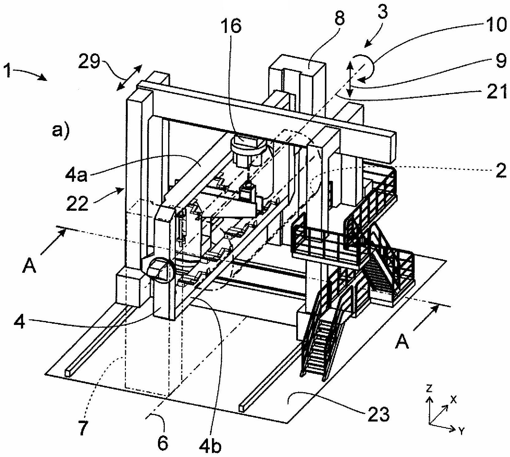
  • 1 eine vorschlagsgemäße Bearbeitungsanlage in einer ersten Bearbeitungsstellung a) in einer perspektivischen Ansicht und b) in einer geschnittenen Ansicht,
  • 2 die Bearbeitungsanlage gemäß 1 in einer zweiten Bearbeitungsstellung a) in einer perspektivischen Ansicht und b) in einer geschnittenen Ansicht und
  • 3 eine schematische Ansicht der Bearbeitungsanlage gemäß 1 in verschiedenen Bearbeitungsstellungen.
In the following the invention will be explained in more detail with reference to a drawing illustrating only embodiments. In the drawing shows
  • 1 a proposed processing plant in a first processing position a) in a perspective view and b) in a sectional view,
  • 2 the processing plant according to 1 in a second processing position a) in a perspective view and b) in a sectional view and
  • 3 a schematic view of the processing plant according to 1 in different machining positions.

Die dargestellte Bearbeitungsanlage 1 dient der Bearbeitung von Flugzeugstrukturbauteilen 2, bei denen es sich, wie weiter oben angesprochen, um Rümpfe, Flügel oder andere große Flugzeugstrukturbauteile handeln kann. Die Bearbeitungsanlage 1 weist eine Bearbeitungsstation 3 auf. Die Bearbeitungsstation 3 weist zum Einen einen Aufspannrahmen 4 zur Aufnahme des jeweils zu bearbeitenden Flugzeugstrukturbauteils 2 und zum Anderen eine Bearbeitungseinheit 5 für die Bearbeitung des Flugzeugstrukturbauteils 2 auf.The illustrated processing plant 1 serves the processing of aircraft structural components 2 which, as discussed above, may be hulls, wings or other large aircraft structural components. The processing plant 1 has a processing station 3 on. The processing station 3 on the one hand has a Aufspannrahmen 4 for receiving the respective aircraft structural component to be processed 2 and on the other hand, a processing unit 5 for the processing of the aircraft structural component 2 on.

Der Aufspannrahmen 4 erstreckt sich entlang einer Stationslängsachse 6, die in eine Längsrichtung X der Bearbeitungsanlage 1 verläuft. Die Erstreckung des Aufspannrahmens 4 entlang der Stationslängsachse 6 ist weit zu verstehen. Sie bedeutet, dass der Aufspannrahmen 4 zumindest in einer Grundstellung parallel zu der Stationslängsachse 6 verläuft, beispielsweise wenn der Aufspannrahmen 4 vertikal ausgerichtet ist und/oder horizontal ausgerichtet ist.The clamping frame 4 extends along a station longitudinal axis 6 in a longitudinal direction X the processing plant 1 runs. The extent of the Aufspannrahmens 4 along the station's longitudinal axis 6 is to be understood. It means that the clamping frame 4 at least in a basic position parallel to the station longitudinal axis 6 runs, for example, when the Aufspannrahmen 4 is vertically aligned and / or oriented horizontally.

Der Aufspannrahmen 4 ist hier und vorzugsweise an zwei Positioniertürmen 7, 8, die sich parallel zur Höhenrichtung Z erstrecken, höhenverstellbar und schwenkbar angelenkt. Die Höhenverstellbarkeit ist in 1a mit dem Bezugszeichen 9 und die Schwenkbarkeit mit dem Bezugszeichen 10 angedeutet. Dabei kann die Höhenverstellbarkeit 9 für die beiden Positioniertürme 7, 8 getrennt möglich sein, so dass ein Kippen des Aufspannrahmens 4 um eine quer zur Stationslängsachse 6 verlaufende Kippachse (hier nicht dargestellt) realisierbar ist.The clamping frame 4 is here and preferably at two positioning towers 7 . 8th , which are parallel to the height direction Z extend, height-adjustable and pivotally hinged. The height adjustability is in 1a with the reference number 9 and the pivoting with the reference numeral 10 indicated. Here, the height adjustment 9 for the two positioning towers 7 . 8th be possible separately, allowing a tilting of the Aufspannrahmens 4 around a transverse to the station longitudinal axis 6 extending tilt axis (not shown here) can be realized.

Die Bearbeitungseinheit 5, bei der es sich hier und vorzugsweise um eine Nieteinheit, eine Bohreinheit oder eine kombinierte Niet-/Bohreinheit handelt, umfasst eine Oberwerkzeugeinheit 11 mit einem entlang einer ersten Werkzeugachse 12a ausgerichteten Oberwerkzeug 13 und eine zugeordnete Unterwerkzeugeinheit 14 mit einem entlang einer zweiten Werkzeugachse 12b ausgerichteten Unterwerkzeug 15. Die Oberwerkzeugeinheit 11 und die Unterwerkzeugeinheit 14 bilden jeweils einen Endeffektor, wobei das Oberwerkzeug 13 insbesondere ein Nietkopf oder Bohrkopf ist und das Unterwerkzeug 15 das korrespondierende Gegenstück dazu bildet.The processing unit 5 , which is here and preferably a riveting unit, a drilling unit or a combined rivet / drilling unit, comprises an upper tool unit 11 with one along a first tool axis 12a aligned upper tool 13 and an associated sub tool unit 14 with one along a second tool axis 12b aligned lower tool 15 , The upper tool unit 11 and the lower tool unit 14 each form an end effector, the upper tool 13 in particular, a rivet head or drill head and the lower tool 15 forms the corresponding counterpart to it.

Die erste Werkzeugachse 12a und die zweite Werkzeugachse 12b verlaufen winkelig und hier insbesondere in eine Richtung orthogonal zur Längsrichtung X. Diese Richtung wird hier auch als Höhenrichtung Z bezeichnet. Die erste Werkzeugachse 12a und die zweite Werkzeugachse 12b sind bei dem Ausführungsbeispiel in den 1 bis 3 in jeder Bearbeitungsposition des Oberwerkzeugs 13 und des Unterwerkzeugs 15 koaxial zueinander ausgerichtet, verlaufen also beide fluchtend in der Höhenrichtung Z. Beide Werkzeugachsen 12a, 12b sind im vorliegenden Fall individuell einstellbar, können also unabhängig voneinander in einer zur Höhenrichtung Z orthogonalen Ebene parallelverschoben werden. Die Einstellbarkeit des Unterwerkzeugs 15 bzw. der Unterwerkzeugeinheit 14 ist in 1b mit dem Bezugszeichen 26 und die Einstellbarkeit des Oberwerkzeugs 13 bzw. der Oberwerkzeugeinheit 11 mit dem Bezugszeichen 28 angedeutet. Grundsätzlich wäre es aber auch denkbar, zumindest eine der Werkzeugachsen 12a, 12b, insbesondere die erste Werkzeugachse 12a, relativ zur Stationslängsachse 6 unbeweglich anzuordnen.The first tool axis 12a and the second tool axis 12b extend at an angle and in particular in a direction orthogonal to the longitudinal direction X , This direction is also called height direction Z designated. The first tool axis 12a and the second tool axis 12b are in the embodiment in the 1 to 3 in every machining position of the upper tool 13 and the lower tool 15 Coaxially aligned with each other, so both extend in alignment in the height direction Z , Both tool axes 12a . 12b are individually adjustable in the present case, so they can independently in a height direction Z orthogonal plane are parallel-shifted. The adjustability of the lower tool 15 or the lower tool unit 14 is in 1b with the reference number 26 and the adjustability of the upper tool 13 or the upper tool unit 11 with the reference number 28 indicated. In principle, it would also be conceivable, at least one of the tool axes 12a . 12b , in particular the first tool axis 12a , relative to the station's longitudinal axis 6 immovable to arrange.

Das Oberwerkzeug 13 und das Unterwerkzeug 15 sind bei dem hier beschriebenen Ausführungsbeispiel jeweils an einem zugeordneten Werkzeugträger 16, 17 gelagert, das Oberwerkzeug 13 an einem Oberwerkzeugträger 16 und das Unterwerkzeug 15 an einem Unterwerkzeugträger 17, wobei der Werkzeugträger 16, 17 jeweils Bestandteil der Oberwerkzeugeinheit 11 bzw. Unterwerkzeugeinheit 14 ist. Der Unterwerkzeugträger 17 ist hier um eine zur Höhenrichtung Z parallele Unterwerkzeugträgerachse 18, die eine Drehachse bildet, drehbar, und zwar insbesondere um mindestens 180°, bevorzugt um mindestens 360°, was hier durch das Bezugszeichen 24 angedeutet ist.The upper tool 13 and the lower tool 15 are in the embodiment described here in each case on an associated tool carrier 16 . 17 stored, the upper tool 13 on an upper tool carrier 16 and the lower tool 15 on a lower tool carrier 17 , where the tool carrier 16 . 17 each part of the upper tool unit 11 or lower tool unit 14 is. The lower tool carrier 17 Here is one to the height direction Z parallel lower tool carrier axis 18 , which forms a rotation axis, rotatable, in particular by at least 180 °, preferably by at least 360 °, which here by the reference numeral 24 is indicated.

Interessant ist nun, dass, wie 3 anschaulich zeigt, in mindestens einer Bearbeitungsposition, hier in mehreren Bearbeitungspositionen, des Oberwerkzeugs 13 und/oder des Unterwerkzeugs 15 die jeweilige Werkzeugachse 12a, 12b nicht-koaxial und insbesondere parallelverschoben zur Unterwerkzeugträgerachse 18 verläuft. Mit anderen Worten ist das Oberwerkzeug 13 und das Unterwerkzeug 15, wie die 3a, 3b, 3e und 3f zeigen, so positioniert, dass dessen Werkzeugachse 12a, 12b zur Unterwerkzeugträgerachse 18 versetzt ist. Das Oberwerkzeug 13 und das Unterwerkzeug 15 können aber, wie die 3c und 3d zeigen, jeweils auch in einer Bearbeitungsposition positioniert werden, in der die zugehörige Werkzeugachse 12a, 12b jeweils zur Unterwerkzeugträgerachse 18 koaxial verläuft. Hier und vorzugsweise werden während der Bearbeitung ein und desselben Flugzeugstrukturbauteils 2 nacheinander sowohl Bearbeitungspositionen, bei denen sich die jeweilige Werkzeugachse 12a, 12b nicht-koaxial zur Unterwerkzeugträgerachse 18 erstreckt, als auch Bearbeitungspositionen, bei denen sich die jeweilige Werkzeugachse 12a, 12b koaxial zur Unterwerkzeugträgerachse 18 erstreckt, durchlaufen.It is interesting that, how 3 shows clearly, in at least one processing position, here in several machining positions, the upper tool 13 and / or the lower tool 15 the respective tool axis 12a . 12b non-coaxial and in particular parallel displaced to the lower tool carrier axis 18 runs. In other words, the top tool 13 and the lower tool 15 , as the 3a . 3b . 3e and 3f show, positioned so that its tool axis 12a . 12b to the lower tool carrier axis 18 is offset. The upper tool 13 and the lower tool 15 but can, like the 3c and 3d each also be positioned in a machining position in which the associated tool axis 12a . 12b each to the lower tool carrier axis 18 runs coaxially. Here and preferably will be during the processing of one and the same aircraft structural component 2 successively both machining positions where the respective tool axis 12a . 12b non-coaxial with the lower tool carrier axis 18 extends, as well as machining positions where the respective tool axis 12a . 12b coaxial with the lower tool carrier axis 18 extends, go through.

Der horizontale Versatz zwischen den Werkzeugachsen 12a, 12b und der Unterwerkzeugträgerachse 18 hat den Vorteil, dass in der Höhenrichtung Z oberhalb der Befestigungsebene 19, in der der Unterwerkzeugträger 17 drehbar gelagert ist, ein Freiraum 20 gebildet wird, der sich bis zu einem oberen Teil 17a des Unterwerkzeugträgers 17 erstreckt. Dieser Freiraum 20 dient zur abschnittsweisen Aufnahme des Aufspannrahmens 4 und darauf befestigten Flugzeugstrukturbauteils 2 während verschiedener Bearbeitungsstellungen des Aufspannrahmens 4. In diesen Bearbeitungsstellungen, die in den 3a und 3f gezeigt sind, ist der Aufspannrahmen 4 vertikal ausgerichtet, d. h. die parallel zur Rahmenlängsachse 21 verlaufenden Rahmenteile 4a, 4b sind in der Höhenrichtung Z übereinander angeordnet, wobei abhängig von der jeweiligen Bearbeitungsstellung entweder der Rahmenteil 4a mit einem daran angeordneten Abschnitt des Flugzeugstrukturbauteils 2 oder der Rahmenteil 4b mit einem daran angeordneten Abschnitt des Flugzeugstrukturbauteils 2 in den Freiraum 20 ragt. Da beim Stand der Technik der Freiraum 20 zumindest im Wesentlichen dieselbe Größe haben muss, um denselben Zweck zu erfüllen, allerdings der Unterwerkzeugträger 17 C-förmig ausgestaltet ist und ein unterer Trägerteil des Unterwerkzeugträgers 17 in den Raum zwischen Befestigungsebene 19 des Unterwerkzeugträgers 17 und Unterwerkzeug 15 ragt, muss beim Stand der Technik der notwendige Freiraum 20 oberhalb des unteren Trägerteils des Unterwerkzeugträgers 17 zur Verfügung gestellt werden. Da aber bei der vorschlagsgemäßen Bearbeitungsanlage 1 der Unterwerkzeugträger 17 keinen solchen unteren Trägerteil aufweist, der in den Raum zwischen der Befestigungsebene 19 und dem Unterwerkzeug 15 ragt, ist hier der Freiraum 20 bezogen auf die Höhenrichtung Z weiter unten angeordnet. Entsprechend ist auch das Unterwerkzeug 15 weiter unten angeordnet, wodurch auch die Arbeitshöhe entsprechend verringert wird. Insgesamt kann dadurch die Bearbeitungsanlage 1 zumindest in der Höhenrichtung Z kleiner dimensioniert werden als im Stand der Technik.The horizontal offset between the tool axes 12a . 12b and the lower tool carrier axis 18 has the advantage of being in the height direction Z above the attachment level 19 in which the lower tool carrier 17 is rotatably mounted, a free space 20 is formed, which is up to an upper part 17a of the lower tool carrier 17 extends. This free space 20 serves to receive sections of the Aufspannrahmens 4 and aircraft structural component mounted thereon 2 during various processing positions of the Aufspannrahmens 4 , In these editing positions, which in the 3a and 3f are shown is the Aufspannrahmen 4 vertically aligned, ie parallel to the frame longitudinal axis 21 running frame parts 4a . 4b are in the height direction Z arranged one above the other, wherein depending on the respective machining position, either the frame part 4a with a portion of the aircraft structural component disposed thereon 2 or the frame part 4b with a portion of the aircraft structural component disposed thereon 2 in the open space 20 protrudes. As in the prior art, the free space 20 at least substantially the same size to fulfill the same purpose, but the lower tool carrier 17 C-shaped and a lower support part of the lower tool carrier 17 in the space between attachment level 19 of the lower tool carrier 17 and lower tool 15 stands in the state of the art, the necessary freedom 20 above the lower support part of the lower tool carrier 17 to provide. But since in the proposed processing plant 1 the lower tool carrier 17 does not have such a lower support part in the space between the mounting plane 19 and the lower tool 15 stands out, here is the open space 20 related to the height direction Z arranged further down. Corresponding is also the lower tool 15 arranged lower down, whereby the working height is reduced accordingly. Overall, thereby the processing plant 1 at least in the height direction Z smaller dimensions than in the prior art.

Neben den dadurch ermöglichten kleineren Dimensionen der Bearbeitungsanlage 1 ist ein weiterer Vorteil der vorschlagsgemäßen Lösung, dass die Werkzeuge 13, 15, aber auch weitere Komponenten der Bearbeitungsanlage 1, besser zugänglich sind. Auch die Bearbeitung von 180°-Schalen als Flugzeugstrukturbauteil 2, wie im vorliegenden Ausführungsbeispiel in den 1 bis 3 dargestellt, wird dadurch erleichtert.In addition to the thereby enabled smaller dimensions of the processing plant 1 Another advantage of the proposed solution is that the tools 13 . 15 , but also other components of the processing plant 1 , are more accessible. Also the machining of 180 ° shells as aircraft structural component 2 as in the present embodiment in the 1 to 3 represented, thereby facilitated.

Hier und vorzugsweise wird die Befestigungsebene 19, an der der Unterwerkzeugträger 17 drehbar gelagert ist, von einem unteren Gestellteil 22a eines Gestells 22 gebildet, welches hier portalförmig ausgebildet ist. Portalförmig heißt, dass der untere Gestellteil 22a, der in eine zur Längsrichtung X und Höhenrichtung Z orthogonale Querrichtung Y verläuft, beidseitig mit zwei sich in der Höhenrichtung Z erstreckenden Gestellteilen 22b, 22c verbunden ist, die in der Querrichtung Y voneinander beabstandet sind und einen oberen Gestellteil 22d tragen, der sich ebenfalls in der Querrichtung Y erstreckt. Der obere Gestellteil 22d wiederum trägt die Oberwerkzeugeinheit 11. In dem Bereich innerhalb des Gestells 22 verläuft der Aufspannrahmen 4, an dem das zu bearbeitende Flugzeugstrukturbauteil 2 befestigt ist, insbesondere in der Längsrichtung X. Der Aufspannrahmen 4 ist wie zuvor erläutert innerhalb des Gestells 22 um die Rahmeniängsachse 21, die hier zur Stationslängsachse 6 parallel ausgerichtet ist, aber auch zu dieser gekippt werden kann, schwenkbar.Here and preferably, the attachment level 19 at which the lower tool carrier 17 is rotatably supported, from a lower frame part 22a a frame 22 formed, which is designed portal-shaped here. Gantry-shaped means that the lower frame part 22a which is in a longitudinal direction X and height direction Z orthogonal transverse direction Y runs, on both sides with two in the height direction Z extending frame parts 22b . 22c connected in the transverse direction Y spaced apart and an upper frame part 22d wear, which is also in the transverse direction Y extends. The upper frame part 22d again carries the upper tool unit 11 , In the area inside the frame 22 runs the Aufspannrahmen 4 on which the aircraft structural component to be processed 2 is fixed, in particular in the longitudinal direction X , The clamping frame 4 is as previously explained within the frame 22 around the frame longitudinal axis 21 , here to station longitudinal axis 6 is aligned parallel, but can also be tilted to this, swiveling.

Es sei darauf hingewiesen, dass das Gestell 22 der Bearbeitungsanlage 1 grundsätzlich auch anders ausgebildet sein kann, um die Oberwerkzeugeinheit 11 zu tragen. Beispielsweise ist es auch denkbar, dass das Gestell 22 C-förmig ausgebildet ist, also nur einen einzigen seitlichen Gestellteil 22b aufweist, der den unteren Gestellteil 22a mit dem oberen Gestellteil 22d verbindet. Auch ist es denkbar, auf den unteren Gestellteil 22a zu verzichten, wobei dann der Unterwerkzeugträger 17 unabhängig vom Gestell 22 auf dem Untergrund 23 anzuordnen wäre. Es ist aber von Vorteil, den Unterwerkzeugträger 17 fest mit dem Gestell 22 bzw. auf dem unteren Gestellteil 22a anzuordnen, da auf diese Weise die Gesamtheit aus Gestell 22, Oberwerkzeugeinheit 11 und Unterwerkzeugeinheit 14 relativ zum Aufspannrahmen 4 und dem Flugzeugstrukturbauteil 2 in Längsrichtung X bzw. entlang der Stationslängsachse 6 verfahren werden kann, wobei die Oberwerkzeugeinheit 11 zur Unterwerkzeugeinheit 14 immer optimal ausgerichtet bleibt. Die Verfahrbarkeit des Gestells 22 ist in 1a) mit dem Bezugszeichen 29 angedeutet.It should be noted that the frame 22 the processing plant 1 in principle, may also be designed differently to the upper tool unit 11 to wear. For example, it is also conceivable that the frame 22 C-shaped, so only a single side frame part 22b comprising, the lower frame part 22a with the upper frame part 22d combines. It is also conceivable on the lower frame part 22a to dispense, in which case the lower tool carrier 17 regardless of the frame 22 on the ground 23 would be to arrange. But it is advantageous, the lower tool carrier 17 stuck with the frame 22 or on the lower frame part 22a to arrange, as in this way the whole of frame 22 , Upper tool unit 11 and lower tool unit 14 relative to the clamping frame 4 and the aircraft structural component 2 longitudinal X or along the station longitudinal axis 6 can be moved, wherein the upper tool unit 11 to the lower tool unit 14 always optimally aligned. The mobility of the frame 22 is in 1a) with the reference number 29 indicated.

Der Unterwerkzeugträger 17 weist hier einen Tragbalken 17a als oberen Trägerteil und eine Tragsäule 17b als seitlichen Trägerteil auf. Die Tragsäule 17b ist hier und vorzugsweise am unteren Gestellteil 22a drehbar gelagert und erstreckt sich im Wesentlichen in der Höhenrichtung Z. Der Tragbalken 17a ist hier und vorzugsweise beweglich mit der Tragsäule 17b verbunden und erstreckt sich von der Tragsäule 17b ausgehend im Wesentlichen in einer zur Höhenrichtung Z orthogonalen Ebene. Der Tragbalken 17a, der hier in der Höhenrichtung Z linear verfahrbar ist, was mit dem Bezugszeichen 27 angedeutet ist, dient hier zur Lagerung des Unterwerkzeugs 15. Die Einheit aus Tragbalken 17a und Tragsäule 17b bildet hier eine L-Form.The lower tool carrier 17 here has a stringers 17a as upper support part and a support column 17b as a lateral support part. The support column 17b is here and preferably at the lower frame part 22a rotatably mounted and extends substantially in the height direction Z , The stringers 17a is here and preferably movable with the support column 17b connected and extends from the support column 17b starting substantially in a direction to the height Z orthogonal plane. The stringers 17a who is here in the height direction Z is linearly movable, what with the reference numeral 27 is implied serves here for the storage of the lower tool 15 , The unit of stringers 17a and support column 17b here forms an L-shape.

Der Unterwerkzeugträger 17 ist bei dem hier beschriebenen Ausführungsbeispiel am unteren Gestellteil 22a nicht nur drehbar gelagert, sondern auch in der Querrichtung Y linear verfahrbar. Außerdem ist hier und vorzugsweise das Unterwerkzeug 15 am Unterwerkzeugträger 17, insbesondere am oder auf dem Tragbalken 17a, in einer zur Höhenrichtung Z orthogonalen Ebene linear verfahrbar. Die Verfahrbarkeit des Unterwerkzeugträgers 17 bzw. der Tragsäule 17b ist in 1b mit dem Bezugszeichen 25 angedeutet. Auch der bereits erwähnte Oberwerkzeugträger 16 ist an dem oberen Gestellteil 22d in der Querrichtung Y linear verfahrbar, was mit dem Bezugszeichen 28 angedeutet ist.The lower tool carrier 17 is in the embodiment described here on the lower frame part 22a not only rotatably mounted, but also in the transverse direction Y linearly movable. In addition, here and preferably the lower tool 15 on the lower tool carrier 17 , in particular on or on the support beam 17a , in a height direction Z orthogonal plane linearly movable. The mobility of the lower tool carrier 17 or the support column 17b is in 1b with the reference number 25 indicated. Also the already mentioned upper tool carrier 16 is at the upper frame part 22d in the transverse direction Y linearly movable, what with the reference numeral 28 is indicated.

Die einzelnen Drehbewegungen und Linearbewegungen der oben genannten Komponenten der Bearbeitungsanlage 1 können über Antriebsmotoren, insbesondere über voneinander unabhängige Antriebsmotoren, bewirkt werden (nicht dargestellt). So kann die vorschlagsgemäße Bearbeitungsanlage 1 einen oder mehrere der folgenden Antriebsmotoren aufweisen:

  • - einen Antriebsmotor für die Drehbewegung des Unterwerkzeugträgers 17, insbesondere relativ zum unteren Gestellteil 22a,
  • - einen Antriebsmotor für die Linearbewegung des Unterwerkzeugträgers 17, insbesondere relativ zum unteren Gestellteil 22a,
  • - einen Antriebsmotor für die Linearbewegung des Unterwerkzeugs 15, insbesondere relativ zum Unterwerkzeugträger 17,
  • - einen Antriebsmotor für eine Linearbewegung des Tragbalkens 17a des Unterwerkzeugträgers 17, insbesondere relativ zur Tragsäule 17b des Unterwerkzeugträgers 17,
  • - einen Antriebsmotor für die Linearbewegung des Oberwerkzeugträgers 16, insbesondere relativ zum oberen Gestellteil 22d,
  • - einen Antriebsmotor für die Linearbewegung des unteren Gestellteils 22a bzw. des Gestells 22, insbesondere relativ zum Untergrund 23.
The individual rotary movements and linear movements of the above-mentioned components of the processing plant 1 can be effected via drive motors, in particular via mutually independent drive motors (not shown). Thus, the proposed processing plant 1 have one or more of the following drive motors:
  • - A drive motor for the rotational movement of the lower tool carrier 17 , in particular relative to the lower frame part 22a .
  • - A drive motor for the linear movement of the lower tool carrier 17 , in particular relative to the lower frame part 22a .
  • - A drive motor for the linear movement of the lower tool 15 , in particular relative to the lower tool carrier 17 .
  • - A drive motor for a linear movement of the support beam 17a of the lower tool carrier 17 , in particular relative to the support column 17b of the lower tool carrier 17 .
  • - A drive motor for the linear movement of the upper tool carrier 16 , in particular relative to the upper frame part 22d .
  • - A drive motor for the linear movement of the lower frame part 22a or the frame 22 , in particular relative to the ground 23 ,

Durch den vorangehend beschriebenen Aufbau der vorschlagsgemäßen Bearbeitungsanlage 1 lassen sich die einzelnen Komponenten der Bearbeitungsanlage 1 insbesondere derart zueinander ausrichten bzw. anordnen, dass beispielsweise der maximal einstellbare Abstand zwischen der jeweiligen Werkzeugachse 12a, 12b und der Unterwerkzeugträgerachse 18 mindestens 1,0 m, bevorzugt mindestens 2,0 m, besonders bevorzugt mindestens 3,0 m, beträgt (3a, 3b, 3e, 3f). Der Freiraum 20 kann dabei in der Höhenrichtung Z eine Höhe von mindestens 2,0 m, bevorzugt mindestens 2,5 m, besonders bevorzugt mindestens 3,0 m, haben. Insbesondere ist dazu der Tragbalken 17a des Unterwerkzeugträgers 17 mindestens 2,0 m, bevorzugt mindestens 2,5 m, besonders bevorzugt mindestens 3,0 m, von der Befestigungsebene 19 bzw. von dem unterem Gestellteil 22a beabstandet. Die Breite des Freiraums 20 in einer zur Höhenrichtung Z orthogonalen Ebene, insbesondere die maximal einstellbare Breite des Freiraums 20 in der Querrichtung Y, die sich durch die Länge des Tragbalkens 17a ergibt, kann ebenfalls mindestens 2,0 m, bevorzugt mindestens 2,5 m, besonders bevorzugt mindestens 3,0 m, betragen.By the above-described construction of the proposed processing plant 1 can be the individual components of the processing plant 1 in particular to align or arrange such that, for example, the maximum adjustable distance between the respective tool axis 12a . 12b and the lower tool carrier axis 18 at least 1.0 m, preferably at least 2.0 m, particularly preferably at least 3.0 m, is ( 3a . 3b . 3e . 3f) , The open space 20 can do this in the height direction Z a height of at least 2.0 m, preferably at least 2.5 m, more preferably at least 3.0 m have. In particular, this is the stringers 17a of the lower tool carrier 17 at least 2.0 meters, preferably at least 2.5 meters, more preferably at least 3.0 meters, from the attachment plane 19 or from the lower frame part 22a spaced. The width of the open space 20 in one to the height direction Z orthogonal plane, in particular the maximum adjustable width of the free space 20 in the transverse direction Y extending through the length of the supporting beam 17a can also be at least 2.0 m, preferably at least 2.5 m, more preferably at least 3.0 m, amount.

Nach einer weiteren Lehre, der ebenfalls eigenständige Bedeutung zukommt, wird ein Verfahren zur Bearbeitung eines Flugzeugstrukturbauteils 2 mit einer vorschlagsgemäßen Bearbeitungsanlage 1 beansprucht.According to another teaching, which also has independent significance, a method for processing an aircraft structural component is described 2 with a proposed processing plant 1 claimed.

Wesentlich bei dem vorschlagsgemäßen Verfahren ist, dass durch die Ausbildung der vorschlagsgemäßen Bearbeitungsanlage 1 während der Bearbeitung des Flugzeugstrukturbauteils 2, insbesondere während eines Niet- oder Bohrvorgangs, die erste Werkzeugachse 12a und/oder zweite Werkzeugachse 12b zumindest temporär (3a, 3b, 3e, 3f) nicht-koaxial bzw. parallelverschoben zur Unterwerkzeugträgerachse 18 positioniert werden kann bzw. können. Auf diese Weise wird wie zuvor erläutert ein Freiraum 20 geschaffen, der sich in einem Bereich unterhalb des Unterwerkzeugs 15 bis zum unteren Ende des Unterwerkzeugträgers 17 bzw. bis zur Befestigungsebene 19 des Unterwerkzeugträgers 17 erstreckt, in den während der Bearbeitung der Aufspannrahmen 4 zusammen mit dem daran befestigten Flugzeugstrukturbauteil 2 abschnittweise eintauchen kann. Auf diese Weise wird erreicht, dass bei einer vergleichsweise geringen Arbeitshöhe ein Flugzeugstrukturbauteil 2, beispielsweise ein halbschalenförmiger Abschnitt eines Rumpfes, auf einfache Weise bearbeitet werden kann, wobei der Aufspannrahmen 4 mit dem darauf angeordneten Flugzeugstrukturbauteil 2 insbesondere über einen Winkelbereich von 180° oder mehr um eine zur Stationslängsachse 6 insbesondere parallele Rahmenlängsachse 21 geschwenkt werden kann.Essential in the proposed method is that by the formation of the proposed processing plant 1 during processing of the aircraft structural component 2 in particular during a riveting or drilling operation, the first tool axis 12a and / or second tool axis 12b at least temporarily ( 3a . 3b . 3e . 3f) non-coaxial or parallel displaced to the lower tool carrier axis 18 can or can be positioned. In this way, as previously explained, a free space 20 created, located in an area below the lower tool 15 to the lower end of the lower tool carrier 17 or to the attachment level 19 of the lower tool carrier 17 extends into during machining of the clamping frame 4 together with the aircraft structural component attached thereto 2 can dip in sections. In this way it is achieved that at a comparatively low working height, an aircraft structural component 2 , For example, a half-shell-shaped portion of a hull, can be easily edited, the Aufspannrahmen 4 with the aircraft structural component arranged thereon 2 in particular over an angular range of 180 ° or more about a station longitudinal axis 6 in particular parallel frame longitudinal axis 21 can be swiveled.

ZITATE ENTHALTEN IN DER BESCHREIBUNG QUOTES INCLUDE IN THE DESCRIPTION

Diese Liste der vom Anmelder aufgeführten Dokumente wurde automatisiert erzeugt und ist ausschließlich zur besseren Information des Lesers aufgenommen. Die Liste ist nicht Bestandteil der deutschen Patent- bzw. Gebrauchsmusteranmeldung. Das DPMA übernimmt keinerlei Haftung für etwaige Fehler oder Auslassungen.This list of the documents listed by the applicant has been generated automatically and is included solely for the better information of the reader. The list is not part of the German patent or utility model application. The DPMA assumes no liability for any errors or omissions.

Zitierte PatentliteraturCited patent literature

  • US 5778505 [0002]US 5778505 [0002]

Claims (14)

Bearbeitungsanlage für Flugzeugstrukturbauteile (2) mit einer Bearbeitungsstation (3) umfassend einen Aufspannrahmen (4) zur Aufnahme des jeweils zu bearbeitenden Flugzeugstrukturbauteils (2), wobei sich der Aufspannrahmen (4) entlang einer in eine Längsrichtung (X) verlaufenden Stationslängsachse (6) erstreckt, und eine Bearbeitungseinheit (5) für die Bearbeitung des Flugzeugstrukturbauteils (2), die eine Oberwerkzeugeinheit (11) mit einem entlang einer ersten Werkzeugachse (12a) ausgerichteten Oberwerkzeug (13) und eine Unterwerkzeugeinheit (14) mit einem entlang einer zweiten Werkzeugachse (12b) ausgerichteten Unterwerkzeug (15) aufweist, wobei die erste Werkzeugachse (12a) und die zweite Werkzeugachse (12b) parallel zu einer zur Längsrichtung (X) winkeligen, insbesondere orthogonalen, Höhenrichtung (Z) ausgerichtet oder ausrichtbar sind, wobei in mindestens einer Bearbeitungsposition des Oberwerkzeugs (13) und in mindestens einer Bearbeitungsposition des Unterwerkzeugs (15) die erste Werkzeugachse (12a) und die zweite Werkzeugachse (12b) koaxial zueinander ausgerichtet sind und wobei das Unterwerkzeug (15) an einem Unterwerkzeugträger (17) gelagert ist, dadurch gekennzeichnet, dass in mindestens einer Bearbeitungsposition des Oberwerkzeugs (13) und/oder in mindestens einer Bearbeitungsposition des Unterwerkzeugs (15) die jeweilige Werkzeugachse (12a, 12b) nicht-koaxial zur Unterwerkzeugträgerachse (18) verläuft.Machining plant for aircraft structural components (2) with a processing station (3) comprising a clamping frame (4) for receiving the respectively to be processed aircraft structural component (2), wherein the Aufspannrahmen (4) along a longitudinal direction (X) extending station longitudinal axis (6) , and a machining unit (5) for machining the aircraft structural component (2), which has an upper tool unit (11) with an upper tool (13) aligned along a first tool axis (12a) and a lower tool unit (14) with a second tool axis (12b ), wherein the first tool axis (12a) and the second tool axis (12b) are aligned or alignable parallel to a longitudinal direction (X) angled, in particular orthogonal, height direction (Z), wherein in at least one processing position of the Upper tool (13) and in at least one processing position of the lower tool (15) d The first tool axis (12a) and the second tool axis (12b) are aligned coaxially with each other and wherein the lower tool (15) is mounted on a lower tool carrier (17), characterized in that in at least one processing position of the upper tool (13) and / or in at least one processing position of the lower tool (15) the respective tool axis (12a, 12b) non-coaxial with the lower tool carrier axis (18). Bearbeitungsanlage nach Anspruch 1, dadurch gekennzeichnet, dass in der mindestens einen Bearbeitungsposition die jeweilige Werkzeugachse (12a, 12b) parallelverschoben zur Unterwerkzeugträgerachse (18) ist, vorzugsweise, dass in der mindestens einen Bearbeitungsposition der maximal einstellbare Abstand zwischen der jeweiligen Werkzeugachse (12a, 12b) und der Unterwerkzeugträgerachse (18) mindestens 1,0 m, bevorzugt mindestens 2,0 m, besonders bevorzugt mindestens 3,0 m, beträgt.Processing plant after Claim 1 , characterized in that in the at least one machining position, the respective tool axis (12a, 12b) parallel to the lower tool carrier axis (18), preferably that in the at least one machining position, the maximum adjustable distance between the respective tool axis (12a, 12b) and the lower tool carrier axis (18) is at least 1.0 m, preferably at least 2.0 m, particularly preferably at least 3.0 m. Bearbeitungsanlage nach Anspruch 1 oder 2, dadurch gekennzeichnet, dass der Unterwerkzeugträger (17) an einem unteren Gestellteil (22a) drehbar gelagert ist, das sich in einer zur Längsrichtung (X) und Höhenrichtung (Z) orthogonalen Querrichtung (Y) erstreckt, wobei in der mindestens einen Bearbeitungsposition, in der die jeweilige Werkzeugachse (12a, 12b) nicht-koaxial bzw. parallelverschoben zur Unterwerkzeugträgerachse (18) ist, ein Freiraum (20) zwischen Unterwerkzeug (18) und unterem Gestellteil (22a) ausgebildet ist, der sich in der Höhenrichtung (Z) vom unteren Gestellteil (22a) bis zum Unterwerkzeug (15) oder bis zu einem Abschnitt des Unterwerkzeugträgers (17), an dem das Unterwerkzeug (15) gelagert ist, erstreckt, vorzugsweise, dass der Freiraum (20) in der Höhenrichtung (Z) eine Höhe von mindestens 2,0 m, bevorzugt mindestens 2,5 m, besonders bevorzugt mindestens 3,0 m, hat.Processing plant after Claim 1 or 2 , characterized in that the lower tool carrier (17) is rotatably mounted on a lower frame part (22a) which extends in a direction orthogonal to the longitudinal direction (X) and height direction (Z) transverse direction (Y), wherein in the at least one processing position, in the respective tool axis (12a, 12b) is non-coaxial or parallel displaced to the lower tool carrier axis (18), a free space (20) between the lower tool (18) and lower frame part (22a) is formed in the height direction (Z) from lower frame part (22a) to the lower tool (15) or to a portion of the lower tool carrier (17) on which the lower tool (15) is mounted, preferably, that the free space (20) in the height direction (Z) has a height of at least 2.0 m, preferably at least 2.5 m, more preferably at least 3.0 m. Bearbeitungsanlage nach einem der vorhergehenden Ansprüche, dadurch gekennzeichnet, dass der Unterwerkzeugträger (17) einen Tragbalken (17a), an dem das Unterwerkzeug (15) gelagert ist, und eine Tragsäule (17b), die drehbar gelagert ist und an der der Tragbalken (17a) befestigt ist, aufweist, vorzugsweise, dass sich der Tragbalken (17a) im Wesentlichen in einer in der Längsrichtung (X) und Querrichtung (Y) verlaufenden Ebene und die Tragsäule (17b) im Wesentlichen in der Höhenrichtung (Z) erstreckt und/oder Tragbalken (17a) und Tragsäule (17b) zusammen eine L-Form bilden.Machining plant according to one of the preceding claims, characterized in that the lower tool carrier (17) has a support beam (17a) on which the lower tool (15) is mounted, and a support column (17b) which is rotatably mounted and on which the support beam (17a ), preferably that the support beam (17a) extends substantially in a plane extending in the longitudinal direction (X) and transverse direction (Y) and the support column (17b) extends substantially in the height direction (Z) and / or Support beam (17 a) and support column (17 b) together form an L-shape. Bearbeitungsanlage nach einem der vorhergehenden Ansprüche, dadurch gekennzeichnet, dass der Tragbalken (17a) mindestens 2,0 m, bevorzugt mindestens 2,5 m, besonders bevorzugt mindestens 3,0 m, vom unteren Gestellteil (22a) beabstandet ist und/oder sich in der in der Längsrichtung (X) und Querrichtung (Y) verlaufenden Ebene von der Tragsäule (17b) aus über eine Länge von mindestens 2,0 m, bevorzugt mindestens 2,5 m, besonders bevorzugt mindestens 3,0 m, erstreckt, vorzugsweise, dass sich der Freiraum (20) zwischen Tragbalken (17a) und unterem Gestellteil (22a) über den größten Teil der Länge des Tragbalkens (17a) erstreckt.Machining plant according to one of the preceding claims, characterized in that the supporting beam (17a) at least 2.0 m, preferably at least 2.5 m, more preferably at least 3.0 m, from the lower frame part (22a) is spaced and / or in extending in the longitudinal direction (X) and transverse direction (Y) extending from the support column (17b) over a length of at least 2.0 m, preferably at least 2.5 m, more preferably at least 3.0 m, preferably in that the free space (20) extends between the support beam (17a) and the lower frame part (22a) over most of the length of the support beam (17a). Bearbeitungsanlage nach einem der vorhergehenden Ansprüche, dadurch gekennzeichnet, dass der Unterwerkzeugträger (17), insbesondere die Tragsäule (17a), am unteren Gestellteil (22a) in der Querrichtung (Y) linear verfahrbar ist.Machining plant according to one of the preceding claims, characterized in that the lower tool carrier (17), in particular the support column (17a), on the lower frame part (22a) in the transverse direction (Y) is linearly movable. Bearbeitungsanlage nach einem der vorhergehenden Ansprüche, dadurch gekennzeichnet, dass das Unterwerkzeug (15) am Unterwerkzeugträger (17), insbesondere am Tragbalken (17a), in einer in der Längsrichtung (X) und Querrichtung (Y) verlaufenden Ebene linear verfahrbar ist, vorzugsweise derart, dass die zweite Werkzeugachse (12b) in mindestens einer Bearbeitungsposition des Unterwerkzeugs (15) koaxial zur Unterwerkzeugträgerachse (18) anordenbar ist.Machining plant according to one of the preceding claims, characterized in that the lower tool (15) on the lower tool carrier (17), in particular on the support beam (17a), in a longitudinal direction (X) and transverse direction (Y) extending plane is linearly movable, preferably such in that the second tool axis (12b) can be arranged coaxially with the lower tool carrier axis (18) in at least one machining position of the lower tool (15). Bearbeitungsanlage nach einem der vorhergehenden Ansprüche, dadurch gekennzeichnet, dass das Oberwerkzeug (13) an einem Oberwerkzeugträger (16) gelagert ist, wobei der Oberwerkzeugträger (16) an einem oberen Gestellteil (22d) gelagert ist, das sich in der Querrichtung (Y) erstreckt, vorzugsweise, dass der Oberwerkzeugträger (16) an dem oberen Gestellteil (22d) in der Querrichtung (Y) linear verfahrbar ist, vorzugsweise derart, dass die erste Werkzeugachse (12a) in mindestens einer Bearbeitungsposition des Oberwerkzeugs (13) koaxial zur Unterwerkzeugträgerachse (18) anordenbar ist. Machining plant according to one of the preceding claims, characterized in that the upper tool (13) is mounted on an upper tool carrier (16), wherein the upper tool carrier (16) is mounted on an upper frame part (22d) which extends in the transverse direction (Y) in that the upper tool carrier (16) is linearly displaceable on the upper frame part (22d) in the transverse direction (Y), preferably such that the first tool axis (12a) is coaxial to the lower tool carrier axis (18) in at least one machining position of the upper tool (13) ) can be arranged. Bearbeitungsanlage nach einem der vorhergehenden Ansprüche, dadurch gekennzeichnet, dass der untere Gestellteil (22a) und obere Gestellteil (22d), insbesondere über mindestens einen seitlichen Gestellteil (22b, 22c), miteinander verbunden sind, vorzugsweise, dass der untere Gestellteil (22d), der mindestens eine seitliche Gestellteil (22b, 22c) und der obere Gestellteil (22d) zusammen eine C-Form oder Portalform bilden.Processing installation according to one of the preceding claims, characterized in that the lower frame part (22a) and upper frame part (22d), in particular via at least one lateral frame part (22b, 22c), are interconnected, preferably that the lower frame part (22d), the at least one lateral frame part (22b, 22c) and the upper frame part (22d) together form a C-shape or portal shape. Bearbeitungsanlage nach einem der vorhergehenden Ansprüche, dadurch gekennzeichnet, dass der untere Gestellteil (22a), insbesondere zusammen mit der Oberwerkzeugeinheit (11) und Unterwerkzeugeinheit (14), in der Längsrichtung (X) linear verfahrbar ist.Machining plant according to one of the preceding claims, characterized in that the lower frame part (22a), in particular together with the upper tool unit (11) and lower tool unit (14), in the longitudinal direction (X) is linearly movable. Bearbeitungsanlage nach einem der vorhergehenden Ansprüche, dadurch gekennzeichnet, dass die Bearbeitungsanlage (1) - einen ersten Antriebsmotor für eine Drehbewegung (24) des Unterwerkzeugträgers (17), insbesondere relativ zum unteren Gestellteil, - einen zweiten Antriebsmotor für eine Linearbewegung (25) des Unterwerkzeugträgers (17), insbesondere relativ zum unteren Gestellteil, - einen dritten Antriebsmotor für eine Linearbewegung (26) des Unterwerkzeugs (15), insbesondere relativ zum Unterwerkzeugträger (17), - einen vierten Antriebsmotor für eine Linearbewegung (27) des Tragbalkens (17a) des Unterwerkzeugträgers (17), insbesondere relativ zur Tragsäule (17b) des Unterwerkzeugträgers (17), - einen fünften Antriebsmotor für eine Linearbewegung (28) des Oberwerkzeugträgers (16), insbesondere relativ zum oberen Gestellteil (22d) und/oder unteren Gestellteil (22a), und/oder - einen sechsten Antriebsmotor für eine Linearbewegung (29) des unteren Gestellteils (22a), insbesondere relativ zum Untergrund (23), aufweist, vorzugsweise, dass der erste Antriebsmotor, der zweite Antriebsmotor, der dritte Antriebsmotor, der vierte Antriebsmotor, der fünfte Antriebsmotor und/oder der sechste Antriebsmotor unabhängig voneinander betätigbar sind.Machining plant according to one of the preceding claims, characterized in that the processing plant (1) - a first drive motor for a rotary movement (24) of the lower tool carrier (17), in particular relative to the lower frame part, - a second drive motor for a linear movement (25) of the lower tool carrier (17), in particular relative to the lower frame part, - a third drive motor for a linear movement (26) of the lower tool (15), in particular relative to the lower tool carrier (17), - a fourth drive motor for a linear movement (27) of the support beam (17a) of the Lower tool carrier (17), in particular relative to the support column (17b) of the lower tool carrier (17), - a fifth drive motor for a linear movement (28) of the upper tool carrier (16), in particular relative to the upper frame part (22d) and / or lower frame part (22a) , and / or - a sixth drive motor for a linear movement (29) of the lower frame part (22a), esp special relative to the substrate (23), preferably, that the first drive motor, the second drive motor, the third drive motor, the fourth drive motor, the fifth drive motor and / or the sixth drive motor are independently operable. Verfahren zur Bearbeitung eines Flugzeugstrukturbauteils (2) mit einer Bearbeitungsanlage (1) nach einem der vorhergehenden Ansprüche, dadurch gekennzeichnet, dass während der Bearbeitung des Flugzeugstrukturbauteils (2), insbesondere während eines Niet- oder Bohrvorgangs, die erste Werkzeugachse (12a) und/oder zweite Werkzeugachse (12b) zumindest temporär nicht-koaxial zur Unterwerkzeugträgerachse (18) verläuft.Method for processing an aircraft structural component (2) with a processing system (1) according to one of the preceding claims, characterized in that during machining of the aircraft structural component (2), in particular during a riveting or drilling operation, the first tool axis (12a) and / or second tool axis (12b) at least temporarily non-coaxial with the lower tool carrier axis (18). Verfahren nach Anspruch 12, dadurch gekennzeichnet, dass während der Bearbeitung des Flugzeugstrukturbauteils (2), insbesondere während eines Niet- oder Bohrvorgangs, die erste Werkzeugachse (12a) und/oder zweite Werkzeugachse (12b) zumindest temporär parallelverschoben zur Unterwerkzeugträgerachse (18) ist.Method according to Claim 12 , characterized in that during the processing of the aircraft structural component (2), in particular during a riveting or drilling operation, the first tool axis (12a) and / or second tool axis (12b) is at least temporarily parallel to the lower tool carrier axis (18). Verfahren nach Anspruch 12 oder 13, dadurch gekennzeichnet, dass der Aufspannrahmen (4) mit dem daran angeordneten Flugzeugstrukturbauteil über einen Winkelbereich von mindestens 180°, vorzugsweise von mehr als 180°, um eine zur Stationslängsachse (6) parallel ausgerichtete und/oder ausrichtbare Rahmenlängsachse (21) geschwenkt wird.Method according to Claim 12 or 13 , characterized in that the Aufspannrahmen (4) with the aircraft structural component arranged thereon over an angular range of at least 180 °, preferably of more than 180 °, about an aligned to the station longitudinal axis (6) aligned and / or alignable frame longitudinal axis (21).
DE102017116716.1A 2017-07-24 2017-07-24 Processing plant for aircraft structural components Pending DE102017116716A1 (en)

Priority Applications (7)

Application Number Priority Date Filing Date Title
DE102017116716.1A DE102017116716A1 (en) 2017-07-24 2017-07-24 Processing plant for aircraft structural components
RU2020102675A RU2768822C2 (en) 2017-07-24 2018-04-27 Processing plant for structural components of aircraft
ES18722011T ES2956114T3 (en) 2017-07-24 2018-04-27 Processing plant for aircraft structural components
PCT/EP2018/060899 WO2019020227A1 (en) 2017-07-24 2018-04-27 Processing system for aircraft structural components
US16/633,739 US11932419B2 (en) 2017-07-24 2018-04-27 Processing system for aircraft structural components
EP18722011.6A EP3658311B1 (en) 2017-07-24 2018-04-27 Processing system for aircraft structural components
CN201880049066.6A CN111201095A (en) 2017-07-24 2018-04-27 Machining device for aircraft structural components

Applications Claiming Priority (1)

Application Number Priority Date Filing Date Title
DE102017116716.1A DE102017116716A1 (en) 2017-07-24 2017-07-24 Processing plant for aircraft structural components

Publications (1)

Publication Number Publication Date
DE102017116716A1 true DE102017116716A1 (en) 2019-01-24

Family

ID=62111061

Family Applications (1)

Application Number Title Priority Date Filing Date
DE102017116716.1A Pending DE102017116716A1 (en) 2017-07-24 2017-07-24 Processing plant for aircraft structural components

Country Status (7)

Country Link
US (1) US11932419B2 (en)
EP (1) EP3658311B1 (en)
CN (1) CN111201095A (en)
DE (1) DE102017116716A1 (en)
ES (1) ES2956114T3 (en)
RU (1) RU2768822C2 (en)
WO (1) WO2019020227A1 (en)

Families Citing this family (3)

* Cited by examiner, † Cited by third party
Publication number Priority date Publication date Assignee Title
DE102017116719A1 (en) * 2017-07-24 2019-01-24 Broetje-Automation Gmbh Processing plant for aircraft structural components
DE102017116716A1 (en) 2017-07-24 2019-01-24 Broetje-Automation Gmbh Processing plant for aircraft structural components
CN113247299B (en) * 2021-07-16 2021-09-28 成都飞机工业(集团)有限责任公司 Wing body finish machining system and method for rapid assembly of airplane

Citations (5)

* Cited by examiner, † Cited by third party
Publication number Priority date Publication date Assignee Title
US4967947A (en) * 1988-03-23 1990-11-06 Branko Sarh Multi-function riveting/fastening machine and method of operating
DE3852634T2 (en) * 1988-04-19 1995-06-22 Aeroflex Tech Inc Riveting process and device.
US5778505A (en) 1994-10-04 1998-07-14 Gemcor Engineering Corporation Apparatus for fastening a semi-cylindrical workpiece
US20120030926A1 (en) * 2006-12-29 2012-02-09 The Boeing Company Robot-deployed assembly tool and method for installing fasteners in aircraft structures
EP2939795A2 (en) * 2014-04-30 2015-11-04 The Boeing Company Mobile automated assembly tool for aircraft structures

Family Cites Families (13)

* Cited by examiner, † Cited by third party
Publication number Priority date Publication date Assignee Title
SU795708A1 (en) * 1979-02-22 1981-01-15 Всесоюзный Проектно-Технологический Инсти-Тут Энергетического Машиностроения Unit for assembling and disassembling riveted articles
SU895587A1 (en) * 1979-12-13 1982-01-07 Предприятие П/Я М-5671 Automatic rivetting plant
SU950474A1 (en) * 1980-11-27 1982-08-15 Предприятие П/Я М-5671 Unit for riveting
FR2647696B1 (en) * 1989-06-06 1991-09-27 Dassault Avions TOOL ASSEMBLY FOR PARTS RIVETING
CA2217892C (en) 1996-10-17 2006-07-18 The Boeing Company Wing panel assembly
WO1999037429A1 (en) * 1998-01-27 1999-07-29 General Electro Mechanical Corporation Apparatus and method for positioning tooling
US6478722B1 (en) * 2000-02-18 2002-11-12 The Boeing Company C-frame assembly apparatus and method for large panel-shaped workpieces
ATE439926T1 (en) * 2003-12-30 2009-09-15 Airbus Gmbh ASSEMBLY DEVICE FOR CONNECTING SHELL-SHAPED LONGITUDINAL SEGMENTS OF A SHEATH BODY BY ATTACHING AT LEAST ONE LONGITUDINAL CONNECTING SEAM
DE102004056285B4 (en) * 2004-11-22 2010-08-26 Airbus Deutschland Gmbh Device with at least two articulated robots for form and / or dimension independent connection of individual components to form sections for aircraft
US8220134B2 (en) * 2008-06-12 2012-07-17 Gemcor Ii, Llc Flexible fastening machine tool
JP5848012B2 (en) * 2011-03-03 2016-01-27 三菱重工業株式会社 Machine Tools
US9937549B2 (en) * 2014-07-09 2018-04-10 The Boeing Company Two-stage riveting
DE102017116716A1 (en) 2017-07-24 2019-01-24 Broetje-Automation Gmbh Processing plant for aircraft structural components

Patent Citations (5)

* Cited by examiner, † Cited by third party
Publication number Priority date Publication date Assignee Title
US4967947A (en) * 1988-03-23 1990-11-06 Branko Sarh Multi-function riveting/fastening machine and method of operating
DE3852634T2 (en) * 1988-04-19 1995-06-22 Aeroflex Tech Inc Riveting process and device.
US5778505A (en) 1994-10-04 1998-07-14 Gemcor Engineering Corporation Apparatus for fastening a semi-cylindrical workpiece
US20120030926A1 (en) * 2006-12-29 2012-02-09 The Boeing Company Robot-deployed assembly tool and method for installing fasteners in aircraft structures
EP2939795A2 (en) * 2014-04-30 2015-11-04 The Boeing Company Mobile automated assembly tool for aircraft structures

Also Published As

Publication number Publication date
US11932419B2 (en) 2024-03-19
CN111201095A (en) 2020-05-26
US20200231305A1 (en) 2020-07-23
RU2020102675A (en) 2021-08-24
WO2019020227A1 (en) 2019-01-31
ES2956114T3 (en) 2023-12-13
EP3658311B1 (en) 2023-06-21
RU2020102675A3 (en) 2021-08-24
RU2768822C2 (en) 2022-03-24
EP3658311A1 (en) 2020-06-03

Similar Documents

Publication Publication Date Title
EP0232548B1 (en) Work station for large work pieces
DE3202353A1 (en) PANTOGRAPH ROD
DE202008007970U1 (en) Construction work tool with swiveling mast
WO2011076249A1 (en) Robot
DE10211816B4 (en) vehicle headlights
EP0812652A1 (en) Device for manufacturing and/or assembling workpieces
DE202015104273U1 (en) processing station
EP3658311B1 (en) Processing system for aircraft structural components
WO2016174133A1 (en) Machining system for aircraft structural components
EP3725593B1 (en) Support device
EP2835203A2 (en) Machine tool and method for machining workpieces with at least two separate machining units
EP3040296A1 (en) Modular mounting transfer system
EP2792448B1 (en) Machining station for structural components of aircraft
EP3658463B1 (en) Machining system for aircraft structural components
DE202004018795U1 (en) Workpiece
DE2110592A1 (en) Device and method for the assembly of curved skin block frames of a ship's hull
EP4117837B1 (en) Bending machine
DE2448367A1 (en) PIT CEILING SUPPORT
DE2263068B2 (en) Compact unit for electrical spot welding
DE19806085B4 (en) Machine tool for 3-axis machining of workpieces
EP3658462B1 (en) Machining facility for aircraft structural components
DE2432877B1 (en) Driving and mining machine
EP2524861B1 (en) Device and method for handling a vehicle assembly tool holder for a vehicle production line, vehicle assembly tool holder and assembly station
DE102012102609B4 (en) Vertically movable lift bed device
DE2747742A1 (en) AUTOMATICALLY MOVABLE WORK EQUIPMENT FOR A TRACTOR

Legal Events

Date Code Title Description
R163 Identified publications notified