EP2962841B1 - Griffversiegelungsmaschine zur Befestigung von mehreren Griffen an einen Beutel - Google Patents
Griffversiegelungsmaschine zur Befestigung von mehreren Griffen an einen Beutel Download PDFInfo
- Publication number
- EP2962841B1 EP2962841B1 EP14175464.8A EP14175464A EP2962841B1 EP 2962841 B1 EP2962841 B1 EP 2962841B1 EP 14175464 A EP14175464 A EP 14175464A EP 2962841 B1 EP2962841 B1 EP 2962841B1
- Authority
- EP
- European Patent Office
- Prior art keywords
- strips
- handles
- strip
- longer
- handle
- Prior art date
- Legal status (The legal status is an assumption and is not a legal conclusion. Google has not performed a legal analysis and makes no representation as to the accuracy of the status listed.)
- Active
Links
Images



Classifications
-
- B—PERFORMING OPERATIONS; TRANSPORTING
- B31—MAKING ARTICLES OF PAPER, CARDBOARD OR MATERIAL WORKED IN A MANNER ANALOGOUS TO PAPER; WORKING PAPER, CARDBOARD OR MATERIAL WORKED IN A MANNER ANALOGOUS TO PAPER
- B31B—MAKING CONTAINERS OF PAPER, CARDBOARD OR MATERIAL WORKED IN A MANNER ANALOGOUS TO PAPER
- B31B50/00—Making rigid or semi-rigid containers, e.g. boxes or cartons
-
- B—PERFORMING OPERATIONS; TRANSPORTING
- B31—MAKING ARTICLES OF PAPER, CARDBOARD OR MATERIAL WORKED IN A MANNER ANALOGOUS TO PAPER; WORKING PAPER, CARDBOARD OR MATERIAL WORKED IN A MANNER ANALOGOUS TO PAPER
- B31B—MAKING CONTAINERS OF PAPER, CARDBOARD OR MATERIAL WORKED IN A MANNER ANALOGOUS TO PAPER
- B31B70/00—Making flexible containers, e.g. envelopes or bags
- B31B70/74—Auxiliary operations
- B31B70/86—Forming integral handles or mounting separate handles
- B31B70/864—Mounting separate handles on bags, sheets or webs
-
- B—PERFORMING OPERATIONS; TRANSPORTING
- B31—MAKING ARTICLES OF PAPER, CARDBOARD OR MATERIAL WORKED IN A MANNER ANALOGOUS TO PAPER; WORKING PAPER, CARDBOARD OR MATERIAL WORKED IN A MANNER ANALOGOUS TO PAPER
- B31D—MAKING ARTICLES OF PAPER, CARDBOARD OR MATERIAL WORKED IN A MANNER ANALOGOUS TO PAPER, NOT PROVIDED FOR IN SUBCLASSES B31B OR B31C
- B31D1/00—Multiple-step processes for making flat articles ; Making flat articles
- B31D1/06—Multiple-step processes for making flat articles ; Making flat articles the articles being handles
Definitions
- the present invention generally relates to a machine for attaching handles made of a heat sealable strip on a carrying bag.
- the present invention particularly relates to an automatic handle sealing machine which is suitable for sealing more than two handles simultaneously on a bag.
- the handle sealing machine according to the present invention saves labor, time and allows continuity of the production with safer manufacturing process.
- Heat sealable materials such as non-woven bags are preferred nowadays for producing carrying bags because they are capable of being used many times and also being found environment friendly and resistant.
- a non-woven fabric is made of polyolefin fibers, and particularly of polyester and rayon without knitting.
- handles are generally attached to a bag mouth by ultrasonic sealing method. These machines which seal the handles on a bag mouth are well known in prior art. Attaching handles on a bag is the most time wasting step in a production line. Generally, the step involves manual positioning of the handles. An operator put a handle on the mouth of the bag where the handle is associated with said mouth portion by sealing or any other appropriate method.
- the present invention is concerned with a handle sealing machine (100) for attaching more than two handles, more particularly four handles on a bag at one time, comprising a main unit (110) where handles are attached to a bag, and a supply unit (102) to continuously provide strips (16) in rectilinear form in order to form the handles (104, 105).
- the sealing machine according to an embodiment of the present invention is shown as a whole in Fig. 1 .
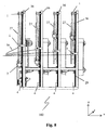
- the supply unit (102) according to an embodiment of the present invention is shown for instance in Figures 8 and 9 where the said strip (16) is winded on reels (27) employed therein. There may be plurality of reels (27), i.e. more than two, depending on the number of handles to be attached onto a particular bag.
- the machine of the present invention further comprises a sealing mechanism (39) having two horns (22) to press and seal the handles on a bag mouth.
- Said supply unit (102) on the other hand has a plurality of rollers (1) on a corresponding supporting bar (36) for guiding and positioning the strips (16) through the main unit (110).
- Required tightness is adjusted by tensioning means (2) associated with the strip (16), and said tensioning means (2) moves on an elevator unit (29) moving along vertical direction (y) provided on each supporting bar (36) of the supply unit (102).
- Strips (16) are cut in required length in the strip cutting station (103) of the main unit (110).
- a strip stopping means (17) runs to immobilize at least two strips (16) so that these immobilized strips constitute the longer handles (104) while the moving strips by way of retraction of the tensioning means (2) will constitute shorter handles (105).
- rotating arms (21) swiveled axially make the handles (104, 105) ready to be sealed on a bag mouth in U shaped form by turning and then the ends of the handles (104, 105) are drawn between the horns (22) which will press the handles (104, 105) on a bag mouth.
- the operator of the machine (100) holds a bag in a proper position and presses the button to seal the handles (104, 105) and then the process is completed.
- the main unit (110) comprises a claw element (33) for holding and delivering the strips (16) to the strip holders (25, 44).
- the claw element (33) moves up by means of an elevator mechanism (34)
- the strip holders (25, 44) move forth in direction (z) and the first strip holder (25) holds the strips (16).
- the claw element (33) releases the ends of the strips (16), and the first strip holder (25) pulls the strips back (16) in direction (x) so as to move away from the claw element (33).
- the strip stopping means (17) immobilizes at least two strips (16), the length of the remaining strips (e.g. two longer strips) stay constant (104), while the other two (105) are shortened.
- the present invention aims at providing an advantageous assembly for sealing of more than two handles in situ as opposed to the prior art arrangements, although the assembly of the present invention is perfectly suited for attachment of four handles at once, two of which are longer than the remaining two such that two handles are formed for shoulder use, and the remaining shorter handles are designed for hand carriage. Therefore, in the most preferred embodiment of the present invention the handle sealing machine disclosed herein is designed for attachment of four handles at once to a bag, and in the following, this embodiment will be disclosed in detail with reference to the drawings.
- a handle sealing machine (100) which is used for attaching handles on a bag mouth, particularly four handles, two of which being short and the remaining two being longer, the said handles can be attached to a bag simultaneously in a machine (100) comprising basically a main unit (110) and a supply unit (102) as shown in Fig. 1 .
- the handle and the bag can be of any heat sealable material such as non-woven fabric and various plastics whereas the sealing method may involve heat and/or ultrasonic welding methods, all of which shall be referred to as a "sealing method" in the following explanations.
- the main unit (110) of the machine (100) stands for operationally attaching of the handles onto a bag, and the supply unit (102) is configured to supply continuously a strip material (16) of the handles to be attached on the bags.
- the main unit (110) of the present invention comprises a machine frame (101) for housing the inner mechanisms.
- a sealing mechanism (39) preferably of ultrasonic type, having horns (22) facing each other where the strips (16) are pressed on a bag mouth.
- Said sealing mechanism (39) is affixed preferably on a lower arm (19) and an upper arm (26) of the machine frame (101).
- the horns (22) of the sealing mechanism (39) are arranged in a face to face arrangement oppositely in order to be able to reciprocate to seal the strips (16) on mouth portion of a bag as can be seen in Figures 4 and 5 .
- the main unit (110) comprises an elevator mechanism (34) where a claw element (33) moves up and down in axis (y).
- Said elevator mechanism (34) lies along width of the machine frame (101).
- a strip holder driving rail (111) on said elevator mechanism (34) which lies between two camshaft gears (43).
- Said strip holder driving rail (111) is adapted so as to allow said claw element (33) move on it in direction (x).
- a strip holder mobile piston (35) is provided to direct the motion of the claw element (33) in vertical direction (y).
- a strip cutting station (103) is provided in the main unit (110).
- Said station (103) is preferably located between the second vertical column (114) and the machine frame (101) where the strips (16) are first received and comprises a strip cutting mobile blade (14) above the stationary blades (15).
- Said blades (14, 15) are connected to a table (30) so as to be one above the other.
- One of the stationary blades (15) is reserved for the upper line of strip (16) while the other is reserved for the lower line of strip (16').
- a strip cutting piston (13) is placed on top of the table (30) to direct the movement of the mobile blade (14).
- strip stopping means (17) which is located so as to be able to hold at least one strip (16) of upper line and at least one strip (16) of lower line (16').
- At least one of the strips in each line stays stationary with a fixed length (loose/longer form) while the other is left free in order to be stayed in tightened form to form shorter strips in the operation unit (18) ( Fig. 6B ).
- at least two driving rails (107) are mounted on the operation unit (18) correspondingly to provide the movement of the carrier unit (23) in axis (z).
- each plate (40) is placed correspondingly and lead to the movement of the rotating arms (21) in axis (x), and each plate (40) has at least one rotating arm (21) mounted on its front section.
- a rod (41) lies above the carrier unit (23) bearing a number of strip length adjustment protrusions (24), two of which are for short handles (105) and the others are for long handles (104). The distance between these protrusions (24) may be adjusted by the operator.
- the claw element (33) which moves on the strip holder driving rail (111) located on the elevator mechanism (34), delivers the strips (16) to the strip holders (25, 44), and when the first strip holder (25) holds the strips (16), the claw element (33) releases the ends of said strips (16), and then the first strip holder (25) pulls the strips (16) away from the claw element (33). Before the first strip holder (25) pulls back the strips (16) in direction (x), the strip stopping means (17) immobilizes the strips (16) that are envisaged to have a longer length.
- the other two strips' length is arranged as shorter to form the shorter handles (105).
- the strips (104), whose length is constant, will be loose and longer.
- second strip holder (44) is activated to hold the four strips (16), and then the strips (16) are cut buy running of the strip cutting station (103).
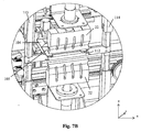
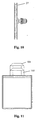
- the rotating arms (21) After cutting the strips (16), the rotating arms (21) set the strips (16) in suitable position to be sealed on a bag mouth by turning and moving them through said bag mouth as shown in Fig. 7A . After that, the plates (40) move forward until the ends of the strips (16) are placed inbetween the horns (22) as shown in Fig. 7B . Lastly, the operator of the machine (100) sets a bag in a suitable position to seal the handles (104, 105) and presses the switch bottom to run the sealing mechanism (39), and thereby the process is completed. The final view of the bag with the attached longer and shorter handles is shown in Fig. 11 .
- the machine (100) structure also comprises a supply unit (102) that has a plurality of reels (27) for accommodating the strips (16) in winded form.
- the strip (16) is passed on rollers (1) which help to draw the strip (16) in required tightness.
- Required tightness is adjusted by a tensioning means (2) preferably embodied as a mass hanged on the strip (16).
- each supporting bar (36) has its own elevator unit (29) where the tensioning means (2) drives on.
- a tension bracket (4) may be provided at the bottom region of the supporting bar (36) and it determines the limits of movement of the tensioning means (2).
- the supply unit (102) may also comprise an actuating means such as an electric motor (3) for actuating rotation of the reels (27) Therefore, a motor activation sensor (not shown) may be located on upper region of in one or more of the supporting bars (36) and also a motor stop sensor (not shown) can be located on lower region of a corresponding supporting bar (36). Said sensors may advantageously adapted to operate according to the movement of the tensioning means (2) which move up and down along the supporting bars (36).
- a method for attachment of more than two handles on a bag comprising the steps of:
Landscapes
- Making Paper Articles (AREA)
Claims (15)
- Griffversiegelungsmaschine (100) zur gleichzeitigen Befestigung von mehr als zwei Griffen (104, 105), hergestellt aus heißversiegelbaren Streifen (16), an einem Beutel, die Maschine (100) umfassend eine Haupteinheit (110) zum Versiegeln der Streifen (16), um Tragegriffe (104, 105) zu bilden, und eine Zuführeinheit (102) zum kontinuierlichen Zuführen von Reihen von Streifen (16) entsprechend jedem der Griffe (104, 105); die Haupteinheit (110) umfassend einen Versiegelungsmechanismus (39), ausgerüstet mit unteren und oberen Hörnern (22), um die Griffe (104, 105) auf einen Beutelmund zu pressen und zu versiegeln, eine Streifenschneidestation (103) zum Schneiden der Streifen (16) und eine Betriebseinheit (18) zur Vorbereitung der Reihe von Streifen (16) in eine versiegelungsbereite Position, dadurch gekennzeichnet, dass die Betriebseinheit (18) erste und zweite Streifenhalter (25, 44), die die Länge der Griffe (104, 105) definieren, und ein Krallenelement (33), das mindestens in horizontalen und vertikalen Richtungen (x, y) mittels eines Hebesystems (34) betreibbar ist, umfasst, wobei das Krallenelement (33) die Endabschnitte der Reihen von Streifen (16) von der Schneidestation (103) erhält und diese zu der Betriebseinheit (18) befördert, wo die ersten und zweiten Halter (25, 44) die Streifen (16) von zwei festgelegten Punkten erhalten, die die Länge der Griffe (104, 105) definieren und die axial drehbar sind, sodass Endabschnitte der resultierenden Griffe (104, 105) in eine versiegelungsbereite Position zwischen den unteren und oberen Hörnern (22) gedreht werden, wobei mindestens einer der zweiten Streifenhalter (44) und die Schneidestation (103) geeignet ist, mindestens einen der Streifen (16) festzuhalten und den Rest zu lassen, um bewegt und durch eine Spannkraft so gespannt zu werden, dass der festgehaltene Streifen (16) eine größere Länge als die anderen Streifen (16) zwischen den ersten und zweiten Streifenhaltern (25, 44) hat und dadurch den längeren Griff (104) verglichen mit den anderen Griffen (105) bildet.
- Griffversiegelungsmaschine nach Anspruch 1, wobei die Maschine (100) ferner ein Spannmittel (2), das mit den Streifen (16) verbunden ist, umfasst.
- Griffversiegelungsmaschine nach Anspruch 2, wobei das Spannmittel (2) als eine Masse angeordnet ist, die mit Schwerkraft auf einer Hebevorrichtung (29) der Zuführeinheit (102) funktioniert.
- Griffversiegelungsmaschine nach Anspruch 1, wobei die Zuführeinheit (102) geeignet ist zum Zuführen von vier Reihen von Streifen (16), wobei mindestens einer der zweiten Streifenhalter (44) und die Schneidestation (103) geeignet ist, zwei der Streifen (16) festzuhalten und die anderen zwei zu lassen, um bewegt und von einer Spannkraft so gespannt zu werden, dass zwei der Streifen (16) eine größere Länge haben als die anderen zwei Streifen (16) zwischen den ersten und zweiten Streifenhaltern (25, 44), um zwei Griffe (104) zu bilden, die länger als die anderen zwei Griffe (105) sind.
- Griffversiegelungsmaschine nach Anspruch 1 oder 4, wobei die Schneidestation (103) Arretierungsmittel (17) umfasst, geeignet zum Festhalten von einem oder mehreren der Streifen (16), um die längeren Griffe (104) zu bilden.
- Griffversiegelungsmaschine nach Anspruch 1, wobei die Betriebseinheit (18) eine Trägereinheit (23) umfasst, geeignet zum Bewegen der Streifenhalter (25, 44) in Achse (z), um die Streifen (16) in Ausrichtung mit dem Krallenelement (33) zu erhalten und diese an eine Versiegelungsposition abzugeben.
- Griffversiegelungsmaschine nach Anspruch 1, wobei der erste Streifenhalter (25) geeignet ist zum Bewegen in horizontaler Achse (x) nach dem Erhalten der Streifen (16) von dem Krallenelement (33), sodass mindestens einer der Streifen (16) in eine lose Position gebracht wird, um den/die längeren Griff(e) (104) zu bilden.
- Griffversiegelungsmaschine nach Anspruch 1, wobei Streifenhalter (25, 44) geeignet sind zum axialen Drehen, um nach Schneiden der Streifen (16) U-förmige Griffe (104, 105) zu bilden.
- Griffversiegelungsmaschine nach Anspruch 1, wobei die Betriebseinheit (18) mindestens zwei Streifenlängenanpassungsvorsprünge (24) umfasst, die die Begrenzungen der Bewegung der Streifenhalter (25, 44) in horizontaler Achse (x) definieren, um die Länge der längeren und kürzeren Griffe (104, 105) anzupassen.
- Verfahren zur gleichzeitigen Befestigung von mehr als zwei Griffen, hergestellt aus heißversiegelbaren Streifen (16), an einem Beutelmund, umfassend die Schritte von:- Bereitstellung von mehr als zwei Reihen von Streifen (16) von einer Zuführeinheit (102) an eine Haupteinheit (110) einer Griffversiegelungsmaschine (100),- Erhalten der Endabschnitte der Streifen (16) mittels eines Krallenelements (33), das mindestens in horizontale und vertikale Richtungen (x, y) betreibbar ist, und Abgeben der Endabschnitte an eine Betriebseinheit (18) der Maschine,- Betreiben eines ersten Streifenhalters (25) zum Erhalten der Endabschnitte der Streifen (16) und Betreiben eines zweiten Streifenhalters (44) zum Halten eines weiteren Abschnitts der Streifen (16), um Längen der dazwischen zu bildenden Griffe (104, 105) zu definieren,- Anwenden einer Spannkraft auf die Streifen (16),- Immobilisieren von mindestens einem Streifen der Reihe von Streifen (16) und Bewegen des ersten Streifenhalters (25) in horizontaler Achse (x), so dass der/die immobilisierte(n) Streifen eine lose Form mit einer längeren Länge verglichen mit dem Rest der Streifen zwischen den ersten und zweiten Streifenhaltern (25, 44) hat, wobei der längere Streifen einen längeren Griff (104) ausmacht und der Rest der Streifen kürzere Griffe (105) ausmacht,- Schneiden der Streifen (16) nach Anordnung von Längen davon wie im vorhergehenden Schritt und Versiegeln von Endabschnitten der so gebildeten Griffe (104, 105) am Mund eines Beutels.
- Verfahren nach Anspruch 10, wobei der Schritt des Anwendens einer Spannkraft durch ein Spannmittel (2) bereitgestellt wird, das als eine Masse angeordnet ist, die mit Schwerkraft auf einer Hebevorrichtung (29) der Zuführeinheit (102) funktioniert.
- Verfahren nach Anspruch 10, wobei das Verfahren das Zuführen von vier Reihen von Streifen (16) zu der Haupteinheit (110) der Maschine (100) umfasst, wobei zwei der Streifenreihen immobilisiert sind, so dass diese immobilisierten Streifen zwei längere Griffe (104) ausmachen und der Rest zwei kürzere Griffe (105) ausmacht.
- Verfahren nach Anspruch 10, wobei das Verfahren ferner die Bereitstellung einer Schneidestation (103) umfassend Schneidklingen (14, 15) und Streifenarretierungsmittel (17) umfasst.
- Verfahren nach Anspruch 10, wobei das Verfahren ferner den Schritt umfasst, in dem die Streifenhalter (25, 44) axial gedreht werden, um nach dem Schneiden der Streifen (16) U-förmige Griffe (104, 105) zu bilden.
- Verfahren nach Anspruch 10, wobei das Verfahren die Bereitstellung von mindestens zwei Streifenlängenanpassungsvorsprüngen (24) umfasst, die die Begrenzungen der Bewegung der Streifenhalter (25, 44) in der horizontalen Achse (x) definieren, um die Länge der längeren und kürzeren Griffe (104, 105) anzupassen.
Priority Applications (1)
| Application Number | Priority Date | Filing Date | Title |
|---|---|---|---|
| EP14175464.8A EP2962841B1 (de) | 2014-07-02 | 2014-07-02 | Griffversiegelungsmaschine zur Befestigung von mehreren Griffen an einen Beutel |
Applications Claiming Priority (1)
| Application Number | Priority Date | Filing Date | Title |
|---|---|---|---|
| EP14175464.8A EP2962841B1 (de) | 2014-07-02 | 2014-07-02 | Griffversiegelungsmaschine zur Befestigung von mehreren Griffen an einen Beutel |
Publications (2)
| Publication Number | Publication Date |
|---|---|
| EP2962841A1 EP2962841A1 (de) | 2016-01-06 |
| EP2962841B1 true EP2962841B1 (de) | 2016-09-14 |
Family
ID=51176125
Family Applications (1)
| Application Number | Title | Priority Date | Filing Date |
|---|---|---|---|
| EP14175464.8A Active EP2962841B1 (de) | 2014-07-02 | 2014-07-02 | Griffversiegelungsmaschine zur Befestigung von mehreren Griffen an einen Beutel |
Country Status (1)
| Country | Link |
|---|---|
| EP (1) | EP2962841B1 (de) |
Cited By (2)
| Publication number | Priority date | Publication date | Assignee | Title |
|---|---|---|---|---|
| CN106584919A (zh) * | 2016-12-21 | 2017-04-26 | 武汉世豪同创自动化设备有限公司 | 手提袋自动穿绳设备 |
| CN108568994B (zh) * | 2018-03-28 | 2019-11-22 | 江苏南江智能装备股份有限公司 | 一种纸制提手加工设备 |
Families Citing this family (4)
| Publication number | Priority date | Publication date | Assignee | Title |
|---|---|---|---|---|
| CN106217854A (zh) * | 2016-08-31 | 2016-12-14 | 温州正钻机械有限公司 | 立体袋把手内折点焊装置 |
| CN108501451A (zh) * | 2018-05-30 | 2018-09-07 | 浙江超伟机械有限公司 | 一种手提袋的手提送料机构 |
| TR201818419A2 (tr) * | 2018-12-03 | 2020-06-22 | Ultrapak Makina Sanayi Ve Ticaret Anonim Sirketi | Sicak mühürleme mekani̇zmasi i̇hti̇va eden bi̇r sap kaynaklama maki̇nesi̇ |
| TR201818423A2 (tr) * | 2018-12-03 | 2020-06-22 | Ultrapak Makina Sanayi Ve Ticaret Anonim Sirketi | Otomati̇ze edi̇lmi̇ş sap kaynaklama maki̇nesi̇ |
Family Cites Families (3)
| Publication number | Priority date | Publication date | Assignee | Title |
|---|---|---|---|---|
| DE1181035B (de) * | 1960-09-22 | 1964-11-05 | Windmoeller & Hoelscher | Verfahren und Vorrichtung zum Herstellen von Tragtaschen aus Beuteln und U-foermigen Traggriffen aus Papier od. dgl. |
| CA900240A (en) | 1970-10-07 | 1972-05-16 | Elwyn D. Jones | Machine for fabricating bag handles |
| IT1192025B (it) * | 1986-05-02 | 1988-03-31 | Wrapmatic Spa | Dispositivo per realizzazione di maniglie da applicare ad un film di materiale per imballaggio e maniglia ottenuta con detto dispos |
-
2014
- 2014-07-02 EP EP14175464.8A patent/EP2962841B1/de active Active
Cited By (3)
| Publication number | Priority date | Publication date | Assignee | Title |
|---|---|---|---|---|
| CN106584919A (zh) * | 2016-12-21 | 2017-04-26 | 武汉世豪同创自动化设备有限公司 | 手提袋自动穿绳设备 |
| CN106584919B (zh) * | 2016-12-21 | 2018-05-22 | 武汉世豪同创自动化设备有限公司 | 手提袋自动穿绳设备 |
| CN108568994B (zh) * | 2018-03-28 | 2019-11-22 | 江苏南江智能装备股份有限公司 | 一种纸制提手加工设备 |
Also Published As
| Publication number | Publication date |
|---|---|
| EP2962841A1 (de) | 2016-01-06 |
Similar Documents
| Publication | Publication Date | Title |
|---|---|---|
| EP2962841A1 (de) | Griffversiegelungsmaschine zur Befestigung von mehreren Griffen an einen Beutel | |
| CN109043698B (zh) | 一种高速折叠口罩机 | |
| CN111201125B (zh) | 用于铺设纤维带的制造设备 | |
| US8500617B2 (en) | Method for manufacturing extraction bag sheet | |
| KR101545427B1 (ko) | 열간 스탬핑 인쇄 장치 | |
| CN110642051B (zh) | 多排料卷自动接驳送料装置 | |
| CN102291861A (zh) | 电热毯多功能自动布线机 | |
| CN105420935A (zh) | 一种左右双向封边机 | |
| WO2019010631A1 (zh) | 一种自动切布机 | |
| JP4978674B2 (ja) | 合成樹脂製袋の玉シール部製造装置及び玉シール部製造方法 | |
| CN104228063A (zh) | 全自动数控v带包带机及包带方法 | |
| CN110424144A (zh) | 一种全自动多层布匹铺设裁床 | |
| KR20210022337A (ko) | 롤백 자동 제조장치 | |
| KR101159446B1 (ko) | 랩핑기의 랩 이송유니트 | |
| CN106042057B (zh) | 橡皮条定位输送切割设备 | |
| CN221518833U (zh) | 一种多功能超声波热合机 | |
| CN111282445B (zh) | 中空纤维膜膜丝固定方法 | |
| CN112339313A (zh) | 一种口罩本体生产机 | |
| CN208068908U (zh) | 一种超声波焊接设备 | |
| FI65929C (fi) | Maskin foer att framstaella med i vaeggar indrivbara faestflikar foersedda hoern- eller kantbeslag foer laodor emballage containers eller andra behaollare | |
| JP5423498B2 (ja) | 未加硫ゴム材料の供給システム | |
| CN210339755U (zh) | 聚酯打包带全自动收卷装置 | |
| CN110316592B (zh) | 聚酯打包带全自动收卷装置 | |
| KR101226199B1 (ko) | 스피드도어의 스크린 제작용 원단의 커팅 및 본딩장치 | |
| JP2578626B2 (ja) | シート状材料の貼付方法およびその装置 |
Legal Events
| Date | Code | Title | Description |
|---|---|---|---|
| PUAI | Public reference made under article 153(3) epc to a published international application that has entered the european phase |
Free format text: ORIGINAL CODE: 0009012 |
|
| 17P | Request for examination filed |
Effective date: 20150306 |
|
| AK | Designated contracting states |
Kind code of ref document: A1 Designated state(s): AL AT BE BG CH CY CZ DE DK EE ES FI FR GB GR HR HU IE IS IT LI LT LU LV MC MK MT NL NO PL PT RO RS SE SI SK SM TR |
|
| AX | Request for extension of the european patent |
Extension state: BA ME |
|
| GRAP | Despatch of communication of intention to grant a patent |
Free format text: ORIGINAL CODE: EPIDOSNIGR1 |
|
| INTG | Intention to grant announced |
Effective date: 20160309 |
|
| GRAS | Grant fee paid |
Free format text: ORIGINAL CODE: EPIDOSNIGR3 |
|
| GRAA | (expected) grant |
Free format text: ORIGINAL CODE: 0009210 |
|
| AK | Designated contracting states |
Kind code of ref document: B1 Designated state(s): AL AT BE BG CH CY CZ DE DK EE ES FI FR GB GR HR HU IE IS IT LI LT LU LV MC MK MT NL NO PL PT RO RS SE SI SK SM TR |
|
| REG | Reference to a national code |
Ref country code: GB Ref legal event code: FG4D |
|
| REG | Reference to a national code |
Ref country code: CH Ref legal event code: EP |
|
| REG | Reference to a national code |
Ref country code: IE Ref legal event code: FG4D |
|
| REG | Reference to a national code |
Ref country code: AT Ref legal event code: REF Ref document number: 828475 Country of ref document: AT Kind code of ref document: T Effective date: 20161015 |
|
| REG | Reference to a national code |
Ref country code: DE Ref legal event code: R096 Ref document number: 602014003601 Country of ref document: DE |
|
| REG | Reference to a national code |
Ref country code: DE Ref legal event code: R079 Ref document number: 602014003601 Country of ref document: DE Free format text: PREVIOUS MAIN CLASS: B31B0019860000 Ipc: B31B0070860000 |
|
| REG | Reference to a national code |
Ref country code: LT Ref legal event code: MG4D |
|
| REG | Reference to a national code |
Ref country code: NL Ref legal event code: MP Effective date: 20160914 |
|
| PG25 | Lapsed in a contracting state [announced via postgrant information from national office to epo] |
Ref country code: HR Free format text: LAPSE BECAUSE OF FAILURE TO SUBMIT A TRANSLATION OF THE DESCRIPTION OR TO PAY THE FEE WITHIN THE PRESCRIBED TIME-LIMIT Effective date: 20160914 Ref country code: LT Free format text: LAPSE BECAUSE OF FAILURE TO SUBMIT A TRANSLATION OF THE DESCRIPTION OR TO PAY THE FEE WITHIN THE PRESCRIBED TIME-LIMIT Effective date: 20160914 Ref country code: RS Free format text: LAPSE BECAUSE OF FAILURE TO SUBMIT A TRANSLATION OF THE DESCRIPTION OR TO PAY THE FEE WITHIN THE PRESCRIBED TIME-LIMIT Effective date: 20160914 Ref country code: NO Free format text: LAPSE BECAUSE OF FAILURE TO SUBMIT A TRANSLATION OF THE DESCRIPTION OR TO PAY THE FEE WITHIN THE PRESCRIBED TIME-LIMIT Effective date: 20161214 Ref country code: FI Free format text: LAPSE BECAUSE OF FAILURE TO SUBMIT A TRANSLATION OF THE DESCRIPTION OR TO PAY THE FEE WITHIN THE PRESCRIBED TIME-LIMIT Effective date: 20160914 |
|
| REG | Reference to a national code |
Ref country code: AT Ref legal event code: MK05 Ref document number: 828475 Country of ref document: AT Kind code of ref document: T Effective date: 20160914 |
|
| PG25 | Lapsed in a contracting state [announced via postgrant information from national office to epo] |
Ref country code: LV Free format text: LAPSE BECAUSE OF FAILURE TO SUBMIT A TRANSLATION OF THE DESCRIPTION OR TO PAY THE FEE WITHIN THE PRESCRIBED TIME-LIMIT Effective date: 20160914 Ref country code: SE Free format text: LAPSE BECAUSE OF FAILURE TO SUBMIT A TRANSLATION OF THE DESCRIPTION OR TO PAY THE FEE WITHIN THE PRESCRIBED TIME-LIMIT Effective date: 20160914 Ref country code: NL Free format text: LAPSE BECAUSE OF FAILURE TO SUBMIT A TRANSLATION OF THE DESCRIPTION OR TO PAY THE FEE WITHIN THE PRESCRIBED TIME-LIMIT Effective date: 20160914 Ref country code: GR Free format text: LAPSE BECAUSE OF FAILURE TO SUBMIT A TRANSLATION OF THE DESCRIPTION OR TO PAY THE FEE WITHIN THE PRESCRIBED TIME-LIMIT Effective date: 20161215 |
|
| PG25 | Lapsed in a contracting state [announced via postgrant information from national office to epo] |
Ref country code: RO Free format text: LAPSE BECAUSE OF FAILURE TO SUBMIT A TRANSLATION OF THE DESCRIPTION OR TO PAY THE FEE WITHIN THE PRESCRIBED TIME-LIMIT Effective date: 20160914 Ref country code: EE Free format text: LAPSE BECAUSE OF FAILURE TO SUBMIT A TRANSLATION OF THE DESCRIPTION OR TO PAY THE FEE WITHIN THE PRESCRIBED TIME-LIMIT Effective date: 20160914 |
|
| PG25 | Lapsed in a contracting state [announced via postgrant information from national office to epo] |
Ref country code: PL Free format text: LAPSE BECAUSE OF FAILURE TO SUBMIT A TRANSLATION OF THE DESCRIPTION OR TO PAY THE FEE WITHIN THE PRESCRIBED TIME-LIMIT Effective date: 20160914 Ref country code: ES Free format text: LAPSE BECAUSE OF FAILURE TO SUBMIT A TRANSLATION OF THE DESCRIPTION OR TO PAY THE FEE WITHIN THE PRESCRIBED TIME-LIMIT Effective date: 20160914 Ref country code: SK Free format text: LAPSE BECAUSE OF FAILURE TO SUBMIT A TRANSLATION OF THE DESCRIPTION OR TO PAY THE FEE WITHIN THE PRESCRIBED TIME-LIMIT Effective date: 20160914 Ref country code: PT Free format text: LAPSE BECAUSE OF FAILURE TO SUBMIT A TRANSLATION OF THE DESCRIPTION OR TO PAY THE FEE WITHIN THE PRESCRIBED TIME-LIMIT Effective date: 20170116 Ref country code: SM Free format text: LAPSE BECAUSE OF FAILURE TO SUBMIT A TRANSLATION OF THE DESCRIPTION OR TO PAY THE FEE WITHIN THE PRESCRIBED TIME-LIMIT Effective date: 20160914 Ref country code: AT Free format text: LAPSE BECAUSE OF FAILURE TO SUBMIT A TRANSLATION OF THE DESCRIPTION OR TO PAY THE FEE WITHIN THE PRESCRIBED TIME-LIMIT Effective date: 20160914 Ref country code: BE Free format text: LAPSE BECAUSE OF FAILURE TO SUBMIT A TRANSLATION OF THE DESCRIPTION OR TO PAY THE FEE WITHIN THE PRESCRIBED TIME-LIMIT Effective date: 20160914 Ref country code: CZ Free format text: LAPSE BECAUSE OF FAILURE TO SUBMIT A TRANSLATION OF THE DESCRIPTION OR TO PAY THE FEE WITHIN THE PRESCRIBED TIME-LIMIT Effective date: 20160914 Ref country code: BG Free format text: LAPSE BECAUSE OF FAILURE TO SUBMIT A TRANSLATION OF THE DESCRIPTION OR TO PAY THE FEE WITHIN THE PRESCRIBED TIME-LIMIT Effective date: 20161214 Ref country code: IS Free format text: LAPSE BECAUSE OF FAILURE TO SUBMIT A TRANSLATION OF THE DESCRIPTION OR TO PAY THE FEE WITHIN THE PRESCRIBED TIME-LIMIT Effective date: 20170114 |
|
| REG | Reference to a national code |
Ref country code: DE Ref legal event code: R097 Ref document number: 602014003601 Country of ref document: DE |
|
| PG25 | Lapsed in a contracting state [announced via postgrant information from national office to epo] |
Ref country code: IT Free format text: LAPSE BECAUSE OF FAILURE TO SUBMIT A TRANSLATION OF THE DESCRIPTION OR TO PAY THE FEE WITHIN THE PRESCRIBED TIME-LIMIT Effective date: 20160914 |
|
| PLBE | No opposition filed within time limit |
Free format text: ORIGINAL CODE: 0009261 |
|
| STAA | Information on the status of an ep patent application or granted ep patent |
Free format text: STATUS: NO OPPOSITION FILED WITHIN TIME LIMIT |
|
| REG | Reference to a national code |
Ref country code: FR Ref legal event code: PLFP Year of fee payment: 4 |
|
| PG25 | Lapsed in a contracting state [announced via postgrant information from national office to epo] |
Ref country code: DK Free format text: LAPSE BECAUSE OF FAILURE TO SUBMIT A TRANSLATION OF THE DESCRIPTION OR TO PAY THE FEE WITHIN THE PRESCRIBED TIME-LIMIT Effective date: 20160914 |
|
| 26N | No opposition filed |
Effective date: 20170615 |
|
| PGFP | Annual fee paid to national office [announced via postgrant information from national office to epo] |
Ref country code: DE Payment date: 20170724 Year of fee payment: 4 Ref country code: FR Payment date: 20170724 Year of fee payment: 4 Ref country code: CH Payment date: 20170719 Year of fee payment: 4 |
|
| PG25 | Lapsed in a contracting state [announced via postgrant information from national office to epo] |
Ref country code: SI Free format text: LAPSE BECAUSE OF FAILURE TO SUBMIT A TRANSLATION OF THE DESCRIPTION OR TO PAY THE FEE WITHIN THE PRESCRIBED TIME-LIMIT Effective date: 20160914 |
|
| REG | Reference to a national code |
Ref country code: IE Ref legal event code: MM4A |
|
| PG25 | Lapsed in a contracting state [announced via postgrant information from national office to epo] |
Ref country code: IE Free format text: LAPSE BECAUSE OF NON-PAYMENT OF DUE FEES Effective date: 20170702 |
|
| PG25 | Lapsed in a contracting state [announced via postgrant information from national office to epo] |
Ref country code: LU Free format text: LAPSE BECAUSE OF NON-PAYMENT OF DUE FEES Effective date: 20170702 |
|
| PG25 | Lapsed in a contracting state [announced via postgrant information from national office to epo] |
Ref country code: MT Free format text: LAPSE BECAUSE OF NON-PAYMENT OF DUE FEES Effective date: 20170702 |
|
| PG25 | Lapsed in a contracting state [announced via postgrant information from national office to epo] |
Ref country code: AL Free format text: LAPSE BECAUSE OF FAILURE TO SUBMIT A TRANSLATION OF THE DESCRIPTION OR TO PAY THE FEE WITHIN THE PRESCRIBED TIME-LIMIT Effective date: 20160914 |
|
| REG | Reference to a national code |
Ref country code: DE Ref legal event code: R119 Ref document number: 602014003601 Country of ref document: DE |
|
| REG | Reference to a national code |
Ref country code: CH Ref legal event code: PL |
|
| GBPC | Gb: european patent ceased through non-payment of renewal fee |
Effective date: 20180702 |
|
| PG25 | Lapsed in a contracting state [announced via postgrant information from national office to epo] |
Ref country code: DE Free format text: LAPSE BECAUSE OF NON-PAYMENT OF DUE FEES Effective date: 20190201 Ref country code: GB Free format text: LAPSE BECAUSE OF NON-PAYMENT OF DUE FEES Effective date: 20180702 Ref country code: FR Free format text: LAPSE BECAUSE OF NON-PAYMENT OF DUE FEES Effective date: 20180731 Ref country code: LI Free format text: LAPSE BECAUSE OF NON-PAYMENT OF DUE FEES Effective date: 20180731 Ref country code: CH Free format text: LAPSE BECAUSE OF NON-PAYMENT OF DUE FEES Effective date: 20180731 |
|
| PG25 | Lapsed in a contracting state [announced via postgrant information from national office to epo] |
Ref country code: MC Free format text: LAPSE BECAUSE OF FAILURE TO SUBMIT A TRANSLATION OF THE DESCRIPTION OR TO PAY THE FEE WITHIN THE PRESCRIBED TIME-LIMIT Effective date: 20160914 Ref country code: HU Free format text: LAPSE BECAUSE OF FAILURE TO SUBMIT A TRANSLATION OF THE DESCRIPTION OR TO PAY THE FEE WITHIN THE PRESCRIBED TIME-LIMIT; INVALID AB INITIO Effective date: 20140702 |
|
| PG25 | Lapsed in a contracting state [announced via postgrant information from national office to epo] |
Ref country code: CY Free format text: LAPSE BECAUSE OF FAILURE TO SUBMIT A TRANSLATION OF THE DESCRIPTION OR TO PAY THE FEE WITHIN THE PRESCRIBED TIME-LIMIT Effective date: 20160914 |
|
| PG25 | Lapsed in a contracting state [announced via postgrant information from national office to epo] |
Ref country code: MK Free format text: LAPSE BECAUSE OF FAILURE TO SUBMIT A TRANSLATION OF THE DESCRIPTION OR TO PAY THE FEE WITHIN THE PRESCRIBED TIME-LIMIT Effective date: 20160914 |
|
| PGFP | Annual fee paid to national office [announced via postgrant information from national office to epo] |
Ref country code: TR Payment date: 20250630 Year of fee payment: 12 |