EP2962829B1 - Procédé de fabrication de pièce moulée par injection en matière expansible et dispositif d'injection associé - Google Patents
Procédé de fabrication de pièce moulée par injection en matière expansible et dispositif d'injection associé Download PDFInfo
- Publication number
- EP2962829B1 EP2962829B1 EP14756937.0A EP14756937A EP2962829B1 EP 2962829 B1 EP2962829 B1 EP 2962829B1 EP 14756937 A EP14756937 A EP 14756937A EP 2962829 B1 EP2962829 B1 EP 2962829B1
- Authority
- EP
- European Patent Office
- Prior art keywords
- injection
- screw
- heating cylinder
- foaming gas
- molten resin
- Prior art date
- Legal status (The legal status is an assumption and is not a legal conclusion. Google has not performed a legal analysis and makes no representation as to the accuracy of the status listed.)
- Active
Links
Images
Classifications
-
- B—PERFORMING OPERATIONS; TRANSPORTING
- B29—WORKING OF PLASTICS; WORKING OF SUBSTANCES IN A PLASTIC STATE IN GENERAL
- B29C—SHAPING OR JOINING OF PLASTICS; SHAPING OF MATERIAL IN A PLASTIC STATE, NOT OTHERWISE PROVIDED FOR; AFTER-TREATMENT OF THE SHAPED PRODUCTS, e.g. REPAIRING
- B29C44/00—Shaping by internal pressure generated in the material, e.g. swelling or foaming ; Producing porous or cellular expanded plastics articles
- B29C44/34—Auxiliary operations
- B29C44/3442—Mixing, kneading or conveying the foamable material
- B29C44/3446—Feeding the blowing agent
-
- B—PERFORMING OPERATIONS; TRANSPORTING
- B29—WORKING OF PLASTICS; WORKING OF SUBSTANCES IN A PLASTIC STATE IN GENERAL
- B29C—SHAPING OR JOINING OF PLASTICS; SHAPING OF MATERIAL IN A PLASTIC STATE, NOT OTHERWISE PROVIDED FOR; AFTER-TREATMENT OF THE SHAPED PRODUCTS, e.g. REPAIRING
- B29C44/00—Shaping by internal pressure generated in the material, e.g. swelling or foaming ; Producing porous or cellular expanded plastics articles
- B29C44/34—Auxiliary operations
- B29C44/36—Feeding the material to be shaped
- B29C44/38—Feeding the material to be shaped into a closed space, i.e. to make articles of definite length
- B29C44/42—Feeding the material to be shaped into a closed space, i.e. to make articles of definite length using pressure difference, e.g. by injection or by vacuum
- B29C44/421—Feeding the material to be shaped into a closed space, i.e. to make articles of definite length using pressure difference, e.g. by injection or by vacuum by plastizising the material into a shot cavity and injecting using a plunger
-
- B—PERFORMING OPERATIONS; TRANSPORTING
- B29—WORKING OF PLASTICS; WORKING OF SUBSTANCES IN A PLASTIC STATE IN GENERAL
- B29C—SHAPING OR JOINING OF PLASTICS; SHAPING OF MATERIAL IN A PLASTIC STATE, NOT OTHERWISE PROVIDED FOR; AFTER-TREATMENT OF THE SHAPED PRODUCTS, e.g. REPAIRING
- B29C45/00—Injection moulding, i.e. forcing the required volume of moulding material through a nozzle into a closed mould; Apparatus therefor
- B29C45/0053—Injection moulding, i.e. forcing the required volume of moulding material through a nozzle into a closed mould; Apparatus therefor combined with a final operation, e.g. shaping
- B29C45/0055—Shaping
-
- B—PERFORMING OPERATIONS; TRANSPORTING
- B29—WORKING OF PLASTICS; WORKING OF SUBSTANCES IN A PLASTIC STATE IN GENERAL
- B29C—SHAPING OR JOINING OF PLASTICS; SHAPING OF MATERIAL IN A PLASTIC STATE, NOT OTHERWISE PROVIDED FOR; AFTER-TREATMENT OF THE SHAPED PRODUCTS, e.g. REPAIRING
- B29C45/00—Injection moulding, i.e. forcing the required volume of moulding material through a nozzle into a closed mould; Apparatus therefor
- B29C45/02—Transfer moulding, i.e. transferring the required volume of moulding material by a plunger from a "shot" cavity into a mould cavity
-
- B—PERFORMING OPERATIONS; TRANSPORTING
- B29—WORKING OF PLASTICS; WORKING OF SUBSTANCES IN A PLASTIC STATE IN GENERAL
- B29C—SHAPING OR JOINING OF PLASTICS; SHAPING OF MATERIAL IN A PLASTIC STATE, NOT OTHERWISE PROVIDED FOR; AFTER-TREATMENT OF THE SHAPED PRODUCTS, e.g. REPAIRING
- B29C45/00—Injection moulding, i.e. forcing the required volume of moulding material through a nozzle into a closed mould; Apparatus therefor
- B29C45/17—Component parts, details or accessories; Auxiliary operations
- B29C45/1701—Component parts, details or accessories; Auxiliary operations using a particular environment during moulding, e.g. moisture-free or dust-free
-
- B—PERFORMING OPERATIONS; TRANSPORTING
- B29—WORKING OF PLASTICS; WORKING OF SUBSTANCES IN A PLASTIC STATE IN GENERAL
- B29C—SHAPING OR JOINING OF PLASTICS; SHAPING OF MATERIAL IN A PLASTIC STATE, NOT OTHERWISE PROVIDED FOR; AFTER-TREATMENT OF THE SHAPED PRODUCTS, e.g. REPAIRING
- B29C45/00—Injection moulding, i.e. forcing the required volume of moulding material through a nozzle into a closed mould; Apparatus therefor
- B29C45/17—Component parts, details or accessories; Auxiliary operations
- B29C45/1703—Introducing an auxiliary fluid into the mould
-
- B—PERFORMING OPERATIONS; TRANSPORTING
- B29—WORKING OF PLASTICS; WORKING OF SUBSTANCES IN A PLASTIC STATE IN GENERAL
- B29C—SHAPING OR JOINING OF PLASTICS; SHAPING OF MATERIAL IN A PLASTIC STATE, NOT OTHERWISE PROVIDED FOR; AFTER-TREATMENT OF THE SHAPED PRODUCTS, e.g. REPAIRING
- B29C45/00—Injection moulding, i.e. forcing the required volume of moulding material through a nozzle into a closed mould; Apparatus therefor
- B29C45/17—Component parts, details or accessories; Auxiliary operations
- B29C45/46—Means for plasticising or homogenising the moulding material or forcing it into the mould
- B29C45/47—Means for plasticising or homogenising the moulding material or forcing it into the mould using screws
- B29C45/50—Axially movable screw
- B29C45/5092—Intrusion moulding, i.e. the screw rotates during injection
-
- B—PERFORMING OPERATIONS; TRANSPORTING
- B29—WORKING OF PLASTICS; WORKING OF SUBSTANCES IN A PLASTIC STATE IN GENERAL
- B29C—SHAPING OR JOINING OF PLASTICS; SHAPING OF MATERIAL IN A PLASTIC STATE, NOT OTHERWISE PROVIDED FOR; AFTER-TREATMENT OF THE SHAPED PRODUCTS, e.g. REPAIRING
- B29C45/00—Injection moulding, i.e. forcing the required volume of moulding material through a nozzle into a closed mould; Apparatus therefor
- B29C45/17—Component parts, details or accessories; Auxiliary operations
- B29C45/46—Means for plasticising or homogenising the moulding material or forcing it into the mould
- B29C45/53—Means for plasticising or homogenising the moulding material or forcing it into the mould using injection ram or piston
- B29C45/54—Means for plasticising or homogenising the moulding material or forcing it into the mould using injection ram or piston and plasticising screw
-
- B—PERFORMING OPERATIONS; TRANSPORTING
- B29—WORKING OF PLASTICS; WORKING OF SUBSTANCES IN A PLASTIC STATE IN GENERAL
- B29C—SHAPING OR JOINING OF PLASTICS; SHAPING OF MATERIAL IN A PLASTIC STATE, NOT OTHERWISE PROVIDED FOR; AFTER-TREATMENT OF THE SHAPED PRODUCTS, e.g. REPAIRING
- B29C45/00—Injection moulding, i.e. forcing the required volume of moulding material through a nozzle into a closed mould; Apparatus therefor
- B29C45/17—Component parts, details or accessories; Auxiliary operations
- B29C45/1701—Component parts, details or accessories; Auxiliary operations using a particular environment during moulding, e.g. moisture-free or dust-free
- B29C2045/1702—Component parts, details or accessories; Auxiliary operations using a particular environment during moulding, e.g. moisture-free or dust-free dissolving or absorbing a fluid in the plastic material
-
- B—PERFORMING OPERATIONS; TRANSPORTING
- B29—WORKING OF PLASTICS; WORKING OF SUBSTANCES IN A PLASTIC STATE IN GENERAL
- B29C—SHAPING OR JOINING OF PLASTICS; SHAPING OF MATERIAL IN A PLASTIC STATE, NOT OTHERWISE PROVIDED FOR; AFTER-TREATMENT OF THE SHAPED PRODUCTS, e.g. REPAIRING
- B29C45/00—Injection moulding, i.e. forcing the required volume of moulding material through a nozzle into a closed mould; Apparatus therefor
- B29C45/17—Component parts, details or accessories; Auxiliary operations
- B29C45/46—Means for plasticising or homogenising the moulding material or forcing it into the mould
- B29C45/53—Means for plasticising or homogenising the moulding material or forcing it into the mould using injection ram or piston
-
- B—PERFORMING OPERATIONS; TRANSPORTING
- B29—WORKING OF PLASTICS; WORKING OF SUBSTANCES IN A PLASTIC STATE IN GENERAL
- B29K—INDEXING SCHEME ASSOCIATED WITH SUBCLASSES B29B, B29C OR B29D, RELATING TO MOULDING MATERIALS OR TO MATERIALS FOR MOULDS, REINFORCEMENTS, FILLERS OR PREFORMED PARTS, e.g. INSERTS
- B29K2067/00—Use of polyesters or derivatives thereof, as moulding material
- B29K2067/003—PET, i.e. poylethylene terephthalate
-
- B—PERFORMING OPERATIONS; TRANSPORTING
- B29—WORKING OF PLASTICS; WORKING OF SUBSTANCES IN A PLASTIC STATE IN GENERAL
- B29K—INDEXING SCHEME ASSOCIATED WITH SUBCLASSES B29B, B29C OR B29D, RELATING TO MOULDING MATERIALS OR TO MATERIALS FOR MOULDS, REINFORCEMENTS, FILLERS OR PREFORMED PARTS, e.g. INSERTS
- B29K2105/00—Condition, form or state of moulded material or of the material to be shaped
- B29K2105/04—Condition, form or state of moulded material or of the material to be shaped cellular or porous
-
- B—PERFORMING OPERATIONS; TRANSPORTING
- B29—WORKING OF PLASTICS; WORKING OF SUBSTANCES IN A PLASTIC STATE IN GENERAL
- B29K—INDEXING SCHEME ASSOCIATED WITH SUBCLASSES B29B, B29C OR B29D, RELATING TO MOULDING MATERIALS OR TO MATERIALS FOR MOULDS, REINFORCEMENTS, FILLERS OR PREFORMED PARTS, e.g. INSERTS
- B29K2995/00—Properties of moulding materials, reinforcements, fillers, preformed parts or moulds
- B29K2995/0018—Properties of moulding materials, reinforcements, fillers, preformed parts or moulds having particular optical properties, e.g. fluorescent or phosphorescent
-
- B—PERFORMING OPERATIONS; TRANSPORTING
- B29—WORKING OF PLASTICS; WORKING OF SUBSTANCES IN A PLASTIC STATE IN GENERAL
- B29L—INDEXING SCHEME ASSOCIATED WITH SUBCLASS B29C, RELATING TO PARTICULAR ARTICLES
- B29L2031/00—Other particular articles
- B29L2031/712—Containers; Packaging elements or accessories, Packages
- B29L2031/7158—Bottles
Definitions
- the present invention relates to a method for producing foamable injection molded product such as a preform that is obtained by dissolving a foaming gas such as an inert gas in a thermoplastic resin, followed by injection molding, as well as to an injection apparatus for producing such foamable injection molded product.
- a synthetic resin bottle obtained by a process in which a preform with a bottomed cylindrical shape (an injection molding) is formed by injection molding by using a thermoplastic resin such as polyethylene terephthalate, and this preform is molded by biaxial stretch blow molding or the like has been generally used in a wide range of fields as a container that accommodates contents such as various beverages.
- thermoplastic resin in order to allow contents that are easily changed in quality by light to be accommodated, known is a technology of imparting light-shielding properties by compounding a colorant such as a pigment with the thermoplastic resin.
- a foaming gas such as an inert gas is dissolved in a resin and generation of foams is suppressed at the time of injection molding of a preform to obtain a preform in a non-foamed state, and this preform is foamed by a heating and blowing process in biaxial stretch blow molding, whereby the preform is molded into a bottle shape that has a large amount of small cells being distributed therein.
- Patent Document 2 a technology utilizing a 2-stage pre-plasticizing injection apparatus that comprises a plasticizing unit and an injection unit has been proposed (see Patent Document 2).
- a molten resin in which a foaming gas such as an inert gas is dissolved in the plasticizing unit is injected into an injection mold by means of a reciprocally-moving plunger that is provided in an injection unit.
- This apparatus is provided with an accumulator in which the molten resin is accumulated through a conduit prior to the injection.
- an object of the present invention is to provide a method for producing a foamable injection molding that is capable of, in injection molding of a foamable injection molded product such as a preform, increasing the time of plasticizing a raw material resin and prolonging the time of injecting a foaming gas to a plasticized molten resin, thereby improving plasticizing of a raw material resin and impregnation of a foaming gas in a molten resin, as well as to an injection apparatus for producing such a foamable injection molded product.
- the method for producing a foamable injection molded product according to the present invention is a method using an injection apparatus comprising a plasticizing unit that plasticizes a raw material resin and an injection unit that injects a plasticized molten resin, and the plasticizing unit is provided with a heating cylinder having a foaming gas injection valve and a screw provided inside the heating cylinder, the method comprises:
- the injection apparatus comprises a plasticizing unit that plasticizes a raw material resin and an injection unit that injects a plasticized molten resin
- the plasticizing unit is provided with a heating cylinder having a foaming gas injection valve, a screw provided inside the heating cylinder, a screw driving part, a screw advancing mechanism, and a back pressure control part, characterized in that the rotation, the advance and retreat movements of the screw, and the resin pressure at the time of plasticizing are controlled by the screw driving part, the screw advancing mechanism, and the back pressure control part such that a raw material resin is plasticized by means of the screw inside the heating cylinder of the plasticizing unit and a foaming gas injected from a foaming gas injection valve is dissolved in the plasticized molten resin, and the screw retreats according as the molten resin accumulates in the front end side of the heating cylinder by the screw that is rotating, the screw advances with rotating to cause the molten resin which has been accumulated in the front end side of the heating cylinder to be transferred
- the present invention in producing a foamable injection molded product by injecting molding a thermoplastic resin in which a foaming gas is dissolved, the time of plasticizing a raw material resin and the time of injecting a foaming gas to a plasticized molten resin in the molding cycle are increased, plasticizing performance and impregnation of a foaming gas are improved, leading to an increase in productivity.
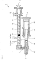
- An injection apparatus 1 shown in FIG. 1 has a plasticizing unit 2 for plasticizing a raw material resin that has been fed and an injection unit 3 for injecting a plasticized molten resin.
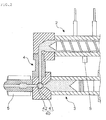
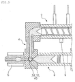
- a heating cylinder 20 that is provided in the plasticizing unit 2 and a heat-retaining cylinder 30 that is provided in the injection unit 3 are arranged in parallel to each other, and the front end sides of these cylinders are connected through a connection part 4 having a rotary valve 40 in its inside.
- a nozzle 5 to be attached to a mold is connected through the connection part 4.
- the rotary valve 40 is provided with a cross head 41 that has a passage with a T-shaped cross section and a hollow part that has a circular cross section and is formed around the intersection of the passage, and a valve 42 that is rotatably attached to the inside of the hollow part formed in the cross head 41 and has a passage having a T-shaped cross section.
- a screw 21 having a helical wing part 22 is arranged within the heating cylinder 20 that is provided in the plasticizing unit 2.
- a screw driving part, a screw advancing mechanism and a back pressure control part all are not shown, the rotation, the advance and retreat movements of the screw 21 in the heating cylinder 20 and the resin pressure at the time of plasticizing can be controlled.
- a hopper 25 for feeding a pelletized raw material resin to the heating cylinder 20 is provided.
- the raw material resin that has been fed to the heating cylinder 20 from the hopper 25 is sent to the front end side of the screw 21 by the screw 21 that rotates within the heating cylinder 20. At the same time, while being sheared, the raw material resin is molten by shear heat and heat of the heater provided in the heating cylinder 20, and is plasticized. The raw material resin that is plasticized in this way is sent to the front end side of the heating cylinder 20 while being kneaded by the rotation of the screw 21.
- foaming gas injection valves 24a and 24b for injecting a foaming gas which is to be dissolved in the plasticized molten resin are provided.
- the foaming gas an inert gas such as a carbon dioxide gas or a nitrogen gas can be used.
- a check valve 23 that opens in a direction in which the molten resin that has been fed from the hopper 25 and plasticized is sent to the front end side of the heating cylinder 20 and does not open in the opposite direction, is provided at the screw 21. Then, a foaming gas is dissolved in the plasticized molten resin that has been sent to the front end side of the heating cylinder 20 by the rotation of the screw 21 and has passed the check valve 23 .
- the advance and retreat movements of the screw 21 are controlled such that according as the molten resin that has been plasticized and in which a foaming gas has been dissolved accumulates in the front end side of the heating cylinder 20, the screw 21 retreats in such a manner that it is pushed back by the resin pressure, and then the screw 21 advances when a prescribed amount of the plasticized molten resin is accumulated in the front end side of the heating cylinder 20.
- the resin pressure of the molten resin at a constant level or at a level that is equal to or higher than the constant level by controlling the retreating of the screw 21 by a back pressure control part of the plasticizing unit 2
- foaming of the impregnating inert gas can be suppressed.
- the plasticizing unit 2 transfers the plasticized molten resin in which a foaming gas is dissolved to the injection unit 3 by advancing the screw 21 that has retreated to a prescribed position due to accumulation in the front end side of the heating cylinder 20 of the molten resin in which a foaming gas is dissolved.
- the stroke length for which the screw 21 advances and retreats can be appropriately set in accordance with the amount of the molten resin to be sent to the injection unit 3, i.e. the dimension of an injection molding such as a preform and the number of cavities in a mold.
- the position of a foaming gas injection valve 24 provided on the heating cylinder 20 can be set in accordance with the stroke length for which the screw 21 advances and retreats such that, even when the screw 21 reaches the position where the screw 21 most retreats (hereinafter referred to as the "retreat limit"), the foaming gas injection valve 24 is positioned rearer than the front end of the screw 21.
- the number of the foaming gas injection valve 24 provided on the heating cylinder 20 may be one. In the example shown in FIG. 1 , plural (two) foaming gas injection valves 24a and 24b are provided along the direction of the advance and retreat of the screw 21.
- the foaming gas injection valve 24 is switched such that a foaming gas is injected from the foaming gas injection valve 24 that is positioned rearer than the front end of the screw 21.
- the foaming gas injection valve 24a provided nearer to the front end side of the heating cylinder 20 is positioned on the front end side relative to the front end side of the screw 21.
- injection of a foaming gas from the foaming gas injection valve 24a may be stopped, and the foaming gas injection valve 24 may be switched such that a foaming gas is injected from the foaming gas injection valve 24b that is positioned on the rear end side relative to the front end of the screw 21.
- the position of the check valve 23 provided on the screw 21 can be set such that, even when the screw 21 reaches the position where the screw 21 most advances (hereinafter referred to as the "advance limit"), the check valve 23 can be positioned on the rear end side of the heating cylinder 20 on which the foaming gas injection valve 24 is provided.
- the valves may be positioned on the front end side of the heating cylinder 20 on which the foaming gas injection valve 24 is provided. In such a case, the foaming gas injection valve 24 may be switched such that injection of an inert gas from the foaming gas injection valve 24 stops.
- the check valve 23 is provided on the screw 21.
- This check valve 23 is provided primarily with an aim of preventing the molten resin in which a foaming gas that has been injected to the heating cylinder 20 is dissolved from flowing out to the rear end side of the heating cylinder 20.
- a transfer process is conducted by allowing the screw 21 to advance while rotating.
- an internal pressure (thrust Pm) of the molten resin to be sent to the front end side of the heating cylinder 20 is generated by the rotation of the screw. Therefore, by designing and setting the conditions of the screw 21 such that the thrust Pm becomes larger than the transfer pressure (Pt), there will be no need to provide, on the front end of the screw 21, a check valve or the like that prevents back-rush of the raw material resin.
- the helical wing part 22 that plasticizes the raw material resin can be formed long enough to reach the front end of the screw 21. Accordingly, plasticizing of the raw material resin and kneading of an inert foaming gas and a molten resin can be improved.
- a plunger rod 31 as an injection member is arranged inside the heat-retaining cylinder 30 provided in the injection unit 3.
- a plunger driving part (not shown), the advance and retreat movements of the plunger 32 in the heat-retaining cylinder 30 are controlled.
- the raw material resin is plasticized, and the plasticized molten resin in which a foaming gas is dissolved.
- a molten resin is then transferred to the injection unit 3, and is accumulated in the heat-retaining cylinder 30 of the injection unit 3.
- the plunger rod 31 is pushed back and retreats by the resin pressure of the molten resin accumulated in the heat-retaining cylinder 30.
- the stroke length for which the plunger 32 advances and retreats the molten resin to be injected is weighed.
- the plunger 32 retreats while keeping the resin pressure of the molten resin accumulated in the heat-retaining cylinder 30 to be a constant level or be at a level that is equal to or higher than the constant level.
- the advance and retreat movements thereof are controlled such that it advances when a prescribed amount of the molten resin is accumulated in the heat-retaining cylinder 30.
- the plunger 32 retreats and advances, whereby the molten resin accumulated in the heat-retaining cylinder 30 is weighed, and then a prescribed amount of the molten resin is injected from a nozzle part 5.
- a pelletized raw material resin that has been fed from the hopper 25 to the heating cylinder 20 is plasticized.
- the rotary valve 40 is switched as shown in FIG. 3 , and a raw material resin that has been fed from the hopper 25 is plasticized as mentioned above.
- the screw 21 that rotates in the heating cylinder 20 plasticizes the raw material resin.
- the screw 21 is pushed back and retreats by the resin pressure of the molten resin accumulated in the front end side of the heating cylinder 20 while sending the raw material resin in which a foaming gas is dissolved to the front end side of the heating cylinder 20.
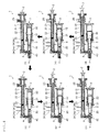
- FIG. 4(a) shows the state where the rotating screw 21 starts to advance in the initial stage of the plasticizing process.
- the screw 21 retreats until it reaches a predetermined stroke or until a predetermined period of time lapses.
- the molten resin that is plasticized and in which a foaming gas is dissolved in the plasticizing unit 2 is transferred to the injection unit 3.
- the rotary valve 40 is switched as shown in FIG. 2 .
- the screw 21 advances while rotating. After that, if necessary, the screw 21 may continue to rotate at the advance limit. As a result, a prescribed amount of the molten resin that is plasticized and in which a foaming gas is dissolved is transferred to the injection unit 3.
- FIG. 4(d) shows a state in which the screw 21 starts to advance while rotating in the initial stage of the transfer process.
- a molten resin accumulated in the front end side of the heating cylinder 20 is transferred to the injection unit 3.
- the screw 21 (see FIG. 4(c) ) that has retreated until it reaches a prescribed stroke or until a prescribed period of time is lapsed in the plasticization process, after the completion of the plasticization process and before the shifting to transfer process, depending on the cycle, stops rotation, and keeps the resin pressure of the molten resin accumulated in the front end side of the heating cylinder 20 at a constant level or at a level that is equal to or higher than the constant level, and advances together with the re-start of the rotation of the screw 21 after the lapse of a prescribed period of time.
- the resin pressure of the resin accumulated in the front end side of the heating cylinder 20 may be kept at a constant level or at a level that is equal to or higher than the constant level, and when the screw 21 retreats until it reaches a prescribed stroke or until a prescribed period of time lapses, the transfer process may start, thereby to allow the screw 21 to advance without stopping the rotation of the screw 21.
- the screw 21 advances to start the transfer process.
- the resin pressure of the molten resin accumulated in the front end side of the heating cylinder 20 can be kept at a constant level during a period of time from the completion of the plasticization process to the shifting of the transfer process.
- the molten resin that has been transferred to the injection unit 3 is accumulated in the heat-retaining cylinder 30 while pushing the plunger rod 31 back to allow it to retreat by the resin pressure (see FIG. 4(e) and FIG. 4(f) ), and is weighed in a prescribed amount in accordance with the stroke length of the plunger rod 31.
- the rotary valve 40 is switched as shown in FIG. 3 , whereafter the above-mentioned the plasticization processes shown in FIG. 4(a) to FIG. 4(c) in sequence re-start.
- the timing when the plasticization process re-starts by switching the rotary valve 40 it may be conducted simultaneously with the time when screw 21 reaches the advance limit or after the screw 21 rotates for a certain period of time at the advance limit or before the screw 21 reaches the advance limit.
- the screw 21 keeps on rotating.
- FIG. 4(a) shows the state where the plunger 32 starts to advance in the initial stage of the injection process.
- a prescribed amount of the molten resin that has been weighed in the heat-retaining cylinder 30 is injected from the nozzle 5.
- the processes mentioned above are repeated to produce a foamable injection molded product.
- the timing when a foaming gas starts to be injected to the molten resin that has been kneaded and plasticized by means of the rotating screw 21 can be controlled as follows.
- the best timing is appropriately selected from (1) to (4) mentioned above.
- the best timing of starting injection can be selected from (1) or (2) taking into consideration the relation with other various conditions.
- the time of starting injection can be selected from (3) or (4).
- Parameters such as the injection pressure, the injection amount or the like of a foaming gas are appropriately set and controlled in advance taking into consideration the optimization of the injection molding.
- timing of starting injection of a foaming gas is controlled in accordance with (1) to (4) mentioned above
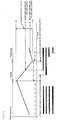
- the relationship between the injection period, the position of the screw 21, the rotation speed of the screw 21 and the resin pressure of the molten resin accumulated in the front end side of the heating cylinder 20, timing of starting injection of a foaming gas, is controlled in accordance with (1) to (4) mentioned above is shown in FIG. 5 .
- FIG. 5 One example of the above-mentioned timing of starting injection of a foaming gas to the plasticized molten resin; i.e. (1), (2), (3) and (4); is shown in FIG. 5 .
- injection period of a foaming gas is shown as a double line and a portion with no double line indicates a period during which injection is stopped.
- the amount of movement of the position of the screw 21 is indicated by a solid line, and the position where the screw 21 most retreats and plasticization is completed (retreat limit) is indicated as Lba and the position where the screw 21 is most advanced (advance limit) is indicated as Lad. Further, a variation in resin pressure of the molten resin accumulated in the front end side of the heating cylinder 20 is indicated by a long dashed short dashed line.
- a foaming gas can be injected to the molten resin in the state being kneaded by the screw 21 that is rotating.
- the screw 21 that has advanced to the advance limit or a position that is immediately before the advance limit in the transfer process starts to retreat while rotating.
- injection of a foaming gas stops. In other words, during a period of time from the start of injection in (1) to (4) mentioned above to the completion of the plasticizing process, a necessary amount of a foaming gas is injected.
- a foaming gas can be injected after the start of the transfer, i.e. immediately after the start of the rotation of the screw. Whereby, for the period of time from the start of the rotation of the screw to the termination of the rotation of the screw, a longer gas injection time can be ensured. As a result, an increase in amount of injected gas can be possible, whereby a gas can be injected uniformly and evenly during the plasticizing process.
- the present invention was explained with reference to preferred embodiments.
- the present invention is not restricted to the above-mentioned embodiments.
- the present invention can be applied to a technology of producing a foamable injection molded product in which a foaming gas such as an inert gas is dissolved in a thermoplastic resin and fine foams are formed at the time of injecting molding an injection molding such as a preform. It is needless to say that various modifications are possible within the scope of the present invention.
- a technology in which a foamable injection molded product is molded by biaxial stretch blow molding in order to mass-produce a synthetic resin-made foamed bottle in which foams are distributed on the bottle wall was given.
- the present invention is not limited to such a technical field, and can be applied to various technical fields as a technology of producing a foamable injection molded product in which a foaming gas such as an inert gas is dissolved.
- the present invention can be applied to various technical fields as a technology of producing a foamable injection molded product in which a foaming gas such as an inert gas is dissolved.
Landscapes
- Engineering & Computer Science (AREA)
- Manufacturing & Machinery (AREA)
- Mechanical Engineering (AREA)
- Injection Moulding Of Plastics Or The Like (AREA)
- Molding Of Porous Articles (AREA)
Claims (13)
- Procédé de fabrication d'un produit moussant moulé par injection en utilisant un appareil d'injection (1), où l'appareil d'injection comprend :une unité de plastification (2) qui plastifie une matière première résineuse,une unité d'injection (3) qui injecte une résine fondue plastifiée, etune pièce de connexion (4) comportant une vanne rotative (40) à l'intérieur ;dans lequel l'unité de plastification est munie d'un cylindre de chauffage (20) ayant une soupape d'injection de gaz moussant (24), une trémie (25), pour alimenter le cylindre de chauffage en matière première résineuse en granulés, prévue sur le côté d'extrémité arrière du cylindre de chauffage, et une vis (21) disposée à l'intérieur du cylindre de chauffage,dans lequel l'unité d'injection est munie d'un cylindre de rétention de chaleur (30) qu'une partie de buse (5) à fixer sur un moule est reliée à l'extrémité avant de celui-ci par la pièce de connexion, etdans lequel les faces frontales du cylindre de chauffage et du cylindre de rétention de chaleur qui sont disposées en parallèle l'une par rapport à l'autre sont reliées par la pièce de connexion,où le procédé comprend :un processus de plastification dans lequel la matière première résineuse est plastifiée au moyen de la vis prévue à l'intérieur du cylindre de chauffage de l'unité de plastification, le gaz moussant injecté par la vanne d'injection de gaz moussant est dissous dans la résine fondue plastifiée,
caractérisé en ce que la vis recule en fonction de l'accumulation de la résine fondue dans la partie avant du cylindre de chauffage par la vis qui tourne,un processus de transfert dans lequel la partie buse est fermée et l'unité de plastification et l'unité d'injection sont reliées par commutation de la vanne rotative, la vis qui a reculé jusqu'à une position prédéterminée est amenée à avancer pendant la rotation, et la résine fondue qui s'est accumulée dans la partie avant du cylindre de chauffage est transférée vers l'unité d'injection ; etun processus d'injection, dans lequel l'unité de plastification est fermée et l'unité d'injection et la partie buse sont reliées par commutation de la vanne rotative, la résine fondue est injectée à partir de l'unité d'injection ;dans lequel, lorsque le processus de transfert est terminé, le processus de plastification redémarre sans arrêter la rotation de la vis et le processus d'injection est effectué, etlorsque le processus d'injection est terminé, le processus de plastification est achevé et le processus de transfert redémarre. - Procédé de production d'un produit moussant moulé par injection selon la revendication 1, dans lequel, après avoir laissé la vis avancer tout en tournant, on continue à faire tourner la vis, ce qui permet de transférer la résine fondue vers l'unité d'injection.
- Procédé de production d'un produit moussant moulé par injection selon la revendication 1 ou 2, dans lequel le gaz moussant est injecté dans la résine fondue qui a été plastifiée au moyen de la vis qui tourne.
- Procédé de production d'un produit moussant moulé par injection selon l'une quelconque des revendications 1 à 3, dans lequel, simultanément au début du processus de transfert ou après l'écoulement d'une période de temps prédéterminée à partir du début du processus de transfert, l'injection d'un gaz moussant commence.
- Procédé de fabrication d'un produit moussant moulé par injection selon l'une quelconque des revendications 1 à 3, dans lequel, après le début du processus de transfert et après que la vis qui avance dans le cylindre de chauffage ait atteint une position prédéterminée, l'injection d'un gaz moussant commence.
- Procédé de fabrication d'un produit moussant moulé par injection selon l'une quelconque des revendications 1 à 3, dans lequel, après l'achèvement du processus de transfert et après l'écoulement d'une période de temps prédéterminée à partir du début du processus de plastification, l'injection d'un gaz moussant commence.
- Procédé de fabrication d'un produit moussant moulé par injection selon l'une quelconque des revendications 1 à 3, dans lequel, après l'achèvement du processus de transfert et après que la vis qui avance à l'intérieur du cylindre de chauffage à partir du début du processus de plastification ait atteint une position prédéterminée, l'injection d'un gaz moussant commence.
- Procédé de production d'un produit moussant moulé par injection selon l'une quelconque des revendications 1 à 7, dans lequel l'injection d'un gaz moussant s'arrête avant la fin du processus de plastification.
- Procédé de production d'un produit moussant moulé par injection selon l'une quelconque des revendications 1 à 8, dans lequel la vis est munie d'un clapet de retenue (23), et la résine fondue qui a été envoyée à la partie avant du cylindre de chauffage par la rotation de la vis et a passé à travers le clapet de retenue est dissoute dans le gaz moussant.
- Appareil d'injection comprenant :une unité de plastification (2) qui plastifie une matière première résineuse,une unité d'injection (3) qui injecte une résine fondue plastifiée, etune pièce de connexion (4) comportant une vanne rotative (40) à l'intérieur ;dans lequel l'unité de plastification est munie d'un cylindre de chauffage (20) ayant une soupape d'injection de gaz moussant (24), une trémie (25), pour alimenter le cylindre de chauffage en matière première résineuse en granulés, prévue sur le côté d'extrémité arrière du cylindre de chauffage, une vis (21) prévue à l'intérieur du cylindre de chauffage, une partie d'entraînement de la vis, un mécanisme d'avancement de la vis, et une partie de contrôle de la contre-pression,dans lequel l'unité d'injection est munie d'un cylindre de rétention de la chaleur (30) qu'une partie de buse (5) à fixer sur un moule est reliée à l'extrémité avant de celui-ci par l'intermédiaire de la pièce de connexion,dans lequel les faces frontales du cylindre de chauffage et du cylindre de rétention de chaleur qui sont disposées en parallèle l'une par rapport à l'autre sont reliées par la pièce de connexion,dans lequel en commutant la vanne rotative pour fermer la partie buse et pour relier l'unité de plastification et l'unité d'injection, la résine fondue qui a été plastifiée dans l'unité de plastification peut être transférée vers l'unité d'injection,dans lequel en commutant la vanne rotative pour fermer l'unité de plastification et pour relier l'unité d'injection et la partie buse, la résine fondue qui a été transférée à l'unité d'injection peut être injectée à partir de la partie buse, etdans lequel la rotation, les mouvements d'avance et de recul de la vis, et la pression de la résine au moment de la plastification sont contrôlés par la partie d'entraînement de la vis, le mécanisme d'avancement de la vis et la partie de contrôle de la contre-pression de telle sorte queune matière première résineuse est plastifiée au moyen de la vis à l'intérieur du cylindre de chauffage de l'unité de plastification et un gaz moussant injecté par une vanne d'injection de gaz moussant est dissous dans la résine fondue plastifiée, etaprès que la vis se soit retirée dans une position prescrite en fonction de l'accumulation de résine fondue dans la partie avant du cylindre de chauffage par la vis qui tourne,la vis avance en tournant pour que la résine fondue qui s'est accumulée à l'extrémité avant du cylindre de chauffage soit transférée dans l'unité d'injection.
- Appareil d'injection selon la revendication 10, dans lequel la soupape d'injection de gaz moussant prévue sur le cylindre de chauffage est autorisée à être commutable de telle sorte que l'injection d'un gaz moussant est conduite à partir de la soupape d'injection de gaz moussant prévue sur le côté d'extrémité arrière par rapport au côté d'extrémité avant de la vis.
- Appareil d'injection selon la revendication 10 ou 11, dans lequel une pluralité de soupapes d'injection de gaz moussant sont prévues.
- Appareil d'injection selon l'une quelconque des revendications 10 à 12, dans lequel un clapet anti-retour positionné à une position plus arrière que la soupape d'injection de gaz moussant et s'ouvrant dans une direction dans laquelle la résine fondue est envoyée vers le côté d'extrémité avant du cylindre de chauffage et ne s'ouvre pas dans une direction opposée à celle ci-dessus est prévu sur la vis.
Applications Claiming Priority (2)
| Application Number | Priority Date | Filing Date | Title |
|---|---|---|---|
| JP2013036044A JP6080611B2 (ja) | 2013-02-26 | 2013-02-26 | 発泡性射出成形体の製造方法及びその射出装置 |
| PCT/JP2014/000876 WO2014132598A1 (fr) | 2013-02-26 | 2014-02-20 | Procédé de fabrication de pièce moulée par injection en matière expansible et dispositif d'injection associé |
Publications (3)
| Publication Number | Publication Date |
|---|---|
| EP2962829A1 EP2962829A1 (fr) | 2016-01-06 |
| EP2962829A4 EP2962829A4 (fr) | 2016-10-26 |
| EP2962829B1 true EP2962829B1 (fr) | 2020-08-12 |
Family
ID=51427877
Family Applications (1)
| Application Number | Title | Priority Date | Filing Date |
|---|---|---|---|
| EP14756937.0A Active EP2962829B1 (fr) | 2013-02-26 | 2014-02-20 | Procédé de fabrication de pièce moulée par injection en matière expansible et dispositif d'injection associé |
Country Status (5)
| Country | Link |
|---|---|
| US (2) | US10160144B2 (fr) |
| EP (1) | EP2962829B1 (fr) |
| JP (1) | JP6080611B2 (fr) |
| CN (1) | CN105073373A (fr) |
| WO (1) | WO2014132598A1 (fr) |
Families Citing this family (11)
| Publication number | Priority date | Publication date | Assignee | Title |
|---|---|---|---|---|
| JP5802689B2 (ja) * | 2013-01-16 | 2015-10-28 | 日精樹脂工業株式会社 | 二液用射出機 |
| JP5799031B2 (ja) * | 2013-01-16 | 2015-10-21 | 日精樹脂工業株式会社 | 二液用射出機 |
| KR102204662B1 (ko) * | 2016-02-22 | 2021-01-19 | 가부시끼가이샤 니혼 세이꼬쇼 | 유로 스위칭 블록이 설치된 사출 장치 |
| US11806908B2 (en) | 2017-06-05 | 2023-11-07 | Otrajet Inc. | Extruding system and method of extruding |
| CN112805132A (zh) * | 2018-09-21 | 2021-05-14 | 耐克创新有限合伙公司 | 模制系统和方法 |
| FR3089767B1 (fr) * | 2018-12-18 | 2020-11-27 | Dior Christian Parfums | Dispositif d’application de produit cosmétique et procédé de fabrication d’un tel dispositif d’application de produit cosmétique |
| JP7238533B2 (ja) * | 2019-03-27 | 2023-03-14 | セイコーエプソン株式会社 | 材料供給装置、射出成形装置及び三次元造形装置 |
| JP7036391B2 (ja) * | 2019-10-15 | 2022-03-15 | オトラジェット インコーポレイテッド. | 押出システム及び押出方法 |
| US12053912B2 (en) * | 2020-07-13 | 2024-08-06 | King Steel Machinery Co., Ltd. | Extruding system and method of extruding a mixture of a polymeric material and a blowing agent |
| AT524784B1 (de) * | 2021-04-07 | 2022-09-15 | Engel Austria Gmbh | Plastifizieraggregat für eine Formgebungsmaschine und Verfahren zum Betreiben eines solchen |
| IT202100028796A1 (it) * | 2021-11-12 | 2023-05-12 | Sipa Progettazione Automaz | Apparato di iniezione per produrre articoli cavi di plastica, in particolare preforme di bottiglie |
Family Cites Families (19)
| Publication number | Priority date | Publication date | Assignee | Title |
|---|---|---|---|---|
| JPS4818365B1 (fr) | 1969-01-28 | 1973-06-05 | ||
| JPS4818365U (fr) | 1971-07-14 | 1973-03-01 | ||
| JPS50144066U (fr) * | 1974-05-21 | 1975-11-28 | ||
| US4211523A (en) | 1978-11-29 | 1980-07-08 | Hoover Universal, Inc. | Gas-flow control apparatus for equipment for producing foamed plastic |
| JPS60220724A (ja) * | 1984-04-17 | 1985-11-05 | Nissei Plastics Ind Co | 予備可塑化装置 |
| JPS63260416A (ja) * | 1986-04-15 | 1988-10-27 | Japan Styrene Paper Co Ltd | 発泡成形体の製造方法 |
| US5997781A (en) | 1996-04-04 | 1999-12-07 | Mitsui Chemicals, Inc. | Injection-expansion molded, thermoplastic resin product and production process thereof |
| JP4144916B2 (ja) * | 1996-04-04 | 2008-09-03 | 三井化学株式会社 | 熱可塑性樹脂発泡射出成形体およびその製造方法 |
| DE29825166U1 (de) | 1997-01-16 | 2005-12-15 | Trexel, Inc., Woburn | Spritzguss mikrozellulären Materials |
| US6884823B1 (en) | 1997-01-16 | 2005-04-26 | Trexel, Inc. | Injection molding of polymeric material |
| JP2001269963A (ja) * | 2000-03-24 | 2001-10-02 | Meiki Co Ltd | 射出装置 |
| DE10055022A1 (de) * | 2000-11-07 | 2002-05-16 | Atecs Mannesmann Ag | Verfahren zur Herstellung eines Formteils aus mikrozellularem Schaum und entsprechende Vorrichtung |
| US7144532B2 (en) * | 2002-10-28 | 2006-12-05 | Trexel, Inc. | Blowing agent introduction systems and methods |
| TWI251532B (en) | 2003-11-14 | 2006-03-21 | Sumitomo Heavy Industries | Injection device and method of heating injection device |
| CN2668374Y (zh) | 2003-12-12 | 2005-01-05 | 南海市佳明机器有限公司 | 注射塑料发泡成型机的注射机构 |
| DE102005033731A1 (de) | 2005-06-23 | 2006-12-28 | Vereinigung zur Förderung des Instituts für Kunststoffverarbeitung in Industrie und Handwerk an der Rhein.-Westf. Technischen Hochschule Aachen eV | Vorrichtung und Verfahren zur Herstellung physikalisch getriebener Schäume |
| TW200829409A (en) | 2006-08-23 | 2008-07-16 | Sulzer Chemtech Ag | A method for the manufacture of a moulding composition |
| JP5414162B2 (ja) | 2006-09-12 | 2014-02-12 | 東洋製罐株式会社 | 遮光性プラスチック容器 |
| CN101554762B (zh) | 2009-05-06 | 2012-05-09 | 联塑(杭州)机械有限公司 | 发泡塑料射出成型方法及其设备 |
-
2013
- 2013-02-26 JP JP2013036044A patent/JP6080611B2/ja active Active
-
2014
- 2014-02-20 WO PCT/JP2014/000876 patent/WO2014132598A1/fr not_active Ceased
- 2014-02-20 EP EP14756937.0A patent/EP2962829B1/fr active Active
- 2014-02-20 US US14/768,819 patent/US10160144B2/en active Active
- 2014-02-20 CN CN201480010146.2A patent/CN105073373A/zh active Pending
-
2018
- 2018-11-14 US US16/190,398 patent/US10543627B2/en active Active
Non-Patent Citations (1)
| Title |
|---|
| None * |
Also Published As
| Publication number | Publication date |
|---|---|
| US10543627B2 (en) | 2020-01-28 |
| WO2014132598A1 (fr) | 2014-09-04 |
| EP2962829A1 (fr) | 2016-01-06 |
| JP6080611B2 (ja) | 2017-02-15 |
| CN105073373A (zh) | 2015-11-18 |
| US10160144B2 (en) | 2018-12-25 |
| US20160001474A1 (en) | 2016-01-07 |
| US20190077059A1 (en) | 2019-03-14 |
| JP2014162144A (ja) | 2014-09-08 |
| EP2962829A4 (fr) | 2016-10-26 |
Similar Documents
| Publication | Publication Date | Title |
|---|---|---|
| US10543627B2 (en) | Method for manufacturing foamable injection molding and injection device therefor | |
| US10315347B2 (en) | Injection molding apparatus with spherical rotor | |
| EP2110223B1 (fr) | Appareil à injection | |
| CN102189650A (zh) | 锥形螺杆注射机 | |
| JP5846998B2 (ja) | 可塑化装置、射出装置、射出成形装置、押出機、及び成形品の製造方法 | |
| KR101372775B1 (ko) | 수지의 다층 사출 성형방법 | |
| US20120242005A1 (en) | Injection Moulding Method | |
| CN101554771B (zh) | 一种聚合物加工装置 | |
| JPH0752185A (ja) | 長繊維複合材料の成形方法及び成形装置 | |
| US20130112782A1 (en) | Injection assembly | |
| CN201456324U (zh) | 带储料桶的注塑挤出装置 | |
| EP3912792B1 (fr) | Procédé d'injection et appareil d'injection de résine fondue, et machine de moulage par injection-étirage-soufflage utilisant l'appareil d'injection | |
| CN201922563U (zh) | 挤出注射成型一体机 | |
| JP2007230087A (ja) | 射出発泡成形装置および射出発泡成形方法 | |
| JP4893220B2 (ja) | 樹脂の多層射出成形方法及び樹脂の多層射出成形装置 | |
| CN202079740U (zh) | 锥形螺杆注射机 | |
| CN101767417A (zh) | 塑注分离式嵌套注射机 | |
| EP4610018A1 (fr) | Tête de vis, dispositif d'injection et machine de moulage par injection-étirage-soufflage utilisant ceux-ci | |
| US20250276479A1 (en) | Screw head, injection device, and injection stretch blow molding machine using the same | |
| JPH0650176Y2 (ja) | 射出装置 | |
| HK40056923A (en) | Injection method and injection apparatus for molten resin, and injection stretch blow molding machine using injection apparatus | |
| JP2004291348A (ja) | 射出成形装置 | |
| JP2004291354A (ja) | サンドイッチ射出成形装置 |
Legal Events
| Date | Code | Title | Description |
|---|---|---|---|
| PUAI | Public reference made under article 153(3) epc to a published international application that has entered the european phase |
Free format text: ORIGINAL CODE: 0009012 |
|
| 17P | Request for examination filed |
Effective date: 20150817 |
|
| AK | Designated contracting states |
Kind code of ref document: A1 Designated state(s): AL AT BE BG CH CY CZ DE DK EE ES FI FR GB GR HR HU IE IS IT LI LT LU LV MC MK MT NL NO PL PT RO RS SE SI SK SM TR |
|
| AX | Request for extension of the european patent |
Extension state: BA ME |
|
| DAX | Request for extension of the european patent (deleted) | ||
| A4 | Supplementary search report drawn up and despatched |
Effective date: 20160922 |
|
| RIC1 | Information provided on ipc code assigned before grant |
Ipc: B29L 31/00 20060101ALN20160916BHEP Ipc: B29C 44/42 20060101ALI20160916BHEP Ipc: B29C 45/00 20060101AFI20160916BHEP Ipc: B29C 44/34 20060101ALI20160916BHEP Ipc: B29K 67/00 20060101ALN20160916BHEP Ipc: B29C 45/54 20060101ALI20160916BHEP Ipc: B29K 105/04 20060101ALN20160916BHEP Ipc: B29C 45/17 20060101ALI20160916BHEP Ipc: B29C 45/50 20060101ALN20160916BHEP |
|
| STAA | Information on the status of an ep patent application or granted ep patent |
Free format text: STATUS: EXAMINATION IS IN PROGRESS |
|
| 17Q | First examination report despatched |
Effective date: 20190924 |
|
| GRAP | Despatch of communication of intention to grant a patent |
Free format text: ORIGINAL CODE: EPIDOSNIGR1 |
|
| STAA | Information on the status of an ep patent application or granted ep patent |
Free format text: STATUS: GRANT OF PATENT IS INTENDED |
|
| INTG | Intention to grant announced |
Effective date: 20200211 |
|
| GRAJ | Information related to disapproval of communication of intention to grant by the applicant or resumption of examination proceedings by the epo deleted |
Free format text: ORIGINAL CODE: EPIDOSDIGR1 |
|
| STAA | Information on the status of an ep patent application or granted ep patent |
Free format text: STATUS: EXAMINATION IS IN PROGRESS |
|
| GRAR | Information related to intention to grant a patent recorded |
Free format text: ORIGINAL CODE: EPIDOSNIGR71 |
|
| GRAS | Grant fee paid |
Free format text: ORIGINAL CODE: EPIDOSNIGR3 |
|
| STAA | Information on the status of an ep patent application or granted ep patent |
Free format text: STATUS: GRANT OF PATENT IS INTENDED |
|
| GRAA | (expected) grant |
Free format text: ORIGINAL CODE: 0009210 |
|
| STAA | Information on the status of an ep patent application or granted ep patent |
Free format text: STATUS: THE PATENT HAS BEEN GRANTED |
|
| INTC | Intention to grant announced (deleted) | ||
| RAP1 | Party data changed (applicant data changed or rights of an application transferred) |
Owner name: TOYO SEIKAN GROUP HOLDINGS, LTD. Owner name: SHIBAURA MACHINE ENGINEERING CO., LTD. |
|
| INTG | Intention to grant announced |
Effective date: 20200701 |
|
| AK | Designated contracting states |
Kind code of ref document: B1 Designated state(s): AL AT BE BG CH CY CZ DE DK EE ES FI FR GB GR HR HU IE IS IT LI LT LU LV MC MK MT NL NO PL PT RO RS SE SI SK SM TR |
|
| REG | Reference to a national code |
Ref country code: CH Ref legal event code: EP |
|
| REG | Reference to a national code |
Ref country code: IE Ref legal event code: FG4D |
|
| REG | Reference to a national code |
Ref country code: DE Ref legal event code: R096 Ref document number: 602014068891 Country of ref document: DE |
|
| REG | Reference to a national code |
Ref country code: AT Ref legal event code: REF Ref document number: 1301120 Country of ref document: AT Kind code of ref document: T Effective date: 20200915 |
|
| REG | Reference to a national code |
Ref country code: LT Ref legal event code: MG4D |
|
| REG | Reference to a national code |
Ref country code: NL Ref legal event code: MP Effective date: 20200812 |
|
| PG25 | Lapsed in a contracting state [announced via postgrant information from national office to epo] |
Ref country code: BG Free format text: LAPSE BECAUSE OF FAILURE TO SUBMIT A TRANSLATION OF THE DESCRIPTION OR TO PAY THE FEE WITHIN THE PRESCRIBED TIME-LIMIT Effective date: 20201112 Ref country code: LT Free format text: LAPSE BECAUSE OF FAILURE TO SUBMIT A TRANSLATION OF THE DESCRIPTION OR TO PAY THE FEE WITHIN THE PRESCRIBED TIME-LIMIT Effective date: 20200812 Ref country code: GR Free format text: LAPSE BECAUSE OF FAILURE TO SUBMIT A TRANSLATION OF THE DESCRIPTION OR TO PAY THE FEE WITHIN THE PRESCRIBED TIME-LIMIT Effective date: 20201113 Ref country code: NO Free format text: LAPSE BECAUSE OF FAILURE TO SUBMIT A TRANSLATION OF THE DESCRIPTION OR TO PAY THE FEE WITHIN THE PRESCRIBED TIME-LIMIT Effective date: 20201112 Ref country code: SE Free format text: LAPSE BECAUSE OF FAILURE TO SUBMIT A TRANSLATION OF THE DESCRIPTION OR TO PAY THE FEE WITHIN THE PRESCRIBED TIME-LIMIT Effective date: 20200812 Ref country code: HR Free format text: LAPSE BECAUSE OF FAILURE TO SUBMIT A TRANSLATION OF THE DESCRIPTION OR TO PAY THE FEE WITHIN THE PRESCRIBED TIME-LIMIT Effective date: 20200812 Ref country code: FI Free format text: LAPSE BECAUSE OF FAILURE TO SUBMIT A TRANSLATION OF THE DESCRIPTION OR TO PAY THE FEE WITHIN THE PRESCRIBED TIME-LIMIT Effective date: 20200812 |
|
| REG | Reference to a national code |
Ref country code: AT Ref legal event code: MK05 Ref document number: 1301120 Country of ref document: AT Kind code of ref document: T Effective date: 20200812 |
|
| PG25 | Lapsed in a contracting state [announced via postgrant information from national office to epo] |
Ref country code: IS Free format text: LAPSE BECAUSE OF FAILURE TO SUBMIT A TRANSLATION OF THE DESCRIPTION OR TO PAY THE FEE WITHIN THE PRESCRIBED TIME-LIMIT Effective date: 20201212 Ref country code: RS Free format text: LAPSE BECAUSE OF FAILURE TO SUBMIT A TRANSLATION OF THE DESCRIPTION OR TO PAY THE FEE WITHIN THE PRESCRIBED TIME-LIMIT Effective date: 20200812 Ref country code: LV Free format text: LAPSE BECAUSE OF FAILURE TO SUBMIT A TRANSLATION OF THE DESCRIPTION OR TO PAY THE FEE WITHIN THE PRESCRIBED TIME-LIMIT Effective date: 20200812 Ref country code: NL Free format text: LAPSE BECAUSE OF FAILURE TO SUBMIT A TRANSLATION OF THE DESCRIPTION OR TO PAY THE FEE WITHIN THE PRESCRIBED TIME-LIMIT Effective date: 20200812 Ref country code: PL Free format text: LAPSE BECAUSE OF FAILURE TO SUBMIT A TRANSLATION OF THE DESCRIPTION OR TO PAY THE FEE WITHIN THE PRESCRIBED TIME-LIMIT Effective date: 20200812 |
|
| PG25 | Lapsed in a contracting state [announced via postgrant information from national office to epo] |
Ref country code: SM Free format text: LAPSE BECAUSE OF FAILURE TO SUBMIT A TRANSLATION OF THE DESCRIPTION OR TO PAY THE FEE WITHIN THE PRESCRIBED TIME-LIMIT Effective date: 20200812 Ref country code: RO Free format text: LAPSE BECAUSE OF FAILURE TO SUBMIT A TRANSLATION OF THE DESCRIPTION OR TO PAY THE FEE WITHIN THE PRESCRIBED TIME-LIMIT Effective date: 20200812 Ref country code: EE Free format text: LAPSE BECAUSE OF FAILURE TO SUBMIT A TRANSLATION OF THE DESCRIPTION OR TO PAY THE FEE WITHIN THE PRESCRIBED TIME-LIMIT Effective date: 20200812 Ref country code: CZ Free format text: LAPSE BECAUSE OF FAILURE TO SUBMIT A TRANSLATION OF THE DESCRIPTION OR TO PAY THE FEE WITHIN THE PRESCRIBED TIME-LIMIT Effective date: 20200812 Ref country code: DK Free format text: LAPSE BECAUSE OF FAILURE TO SUBMIT A TRANSLATION OF THE DESCRIPTION OR TO PAY THE FEE WITHIN THE PRESCRIBED TIME-LIMIT Effective date: 20200812 |
|
| REG | Reference to a national code |
Ref country code: DE Ref legal event code: R097 Ref document number: 602014068891 Country of ref document: DE |
|
| PG25 | Lapsed in a contracting state [announced via postgrant information from national office to epo] |
Ref country code: AL Free format text: LAPSE BECAUSE OF FAILURE TO SUBMIT A TRANSLATION OF THE DESCRIPTION OR TO PAY THE FEE WITHIN THE PRESCRIBED TIME-LIMIT Effective date: 20200812 Ref country code: AT Free format text: LAPSE BECAUSE OF FAILURE TO SUBMIT A TRANSLATION OF THE DESCRIPTION OR TO PAY THE FEE WITHIN THE PRESCRIBED TIME-LIMIT Effective date: 20200812 Ref country code: ES Free format text: LAPSE BECAUSE OF FAILURE TO SUBMIT A TRANSLATION OF THE DESCRIPTION OR TO PAY THE FEE WITHIN THE PRESCRIBED TIME-LIMIT Effective date: 20200812 |
|
| PLBE | No opposition filed within time limit |
Free format text: ORIGINAL CODE: 0009261 |
|
| STAA | Information on the status of an ep patent application or granted ep patent |
Free format text: STATUS: NO OPPOSITION FILED WITHIN TIME LIMIT |
|
| PG25 | Lapsed in a contracting state [announced via postgrant information from national office to epo] |
Ref country code: SK Free format text: LAPSE BECAUSE OF FAILURE TO SUBMIT A TRANSLATION OF THE DESCRIPTION OR TO PAY THE FEE WITHIN THE PRESCRIBED TIME-LIMIT Effective date: 20200812 |
|
| 26N | No opposition filed |
Effective date: 20210514 |
|
| PG25 | Lapsed in a contracting state [announced via postgrant information from national office to epo] |
Ref country code: SI Free format text: LAPSE BECAUSE OF FAILURE TO SUBMIT A TRANSLATION OF THE DESCRIPTION OR TO PAY THE FEE WITHIN THE PRESCRIBED TIME-LIMIT Effective date: 20200812 |
|
| PG25 | Lapsed in a contracting state [announced via postgrant information from national office to epo] |
Ref country code: MC Free format text: LAPSE BECAUSE OF FAILURE TO SUBMIT A TRANSLATION OF THE DESCRIPTION OR TO PAY THE FEE WITHIN THE PRESCRIBED TIME-LIMIT Effective date: 20200812 |
|
| REG | Reference to a national code |
Ref country code: BE Ref legal event code: MM Effective date: 20210228 |
|
| PG25 | Lapsed in a contracting state [announced via postgrant information from national office to epo] |
Ref country code: CH Free format text: LAPSE BECAUSE OF NON-PAYMENT OF DUE FEES Effective date: 20210228 Ref country code: LI Free format text: LAPSE BECAUSE OF NON-PAYMENT OF DUE FEES Effective date: 20210228 Ref country code: LU Free format text: LAPSE BECAUSE OF NON-PAYMENT OF DUE FEES Effective date: 20210220 |
|
| PG25 | Lapsed in a contracting state [announced via postgrant information from national office to epo] |
Ref country code: IE Free format text: LAPSE BECAUSE OF NON-PAYMENT OF DUE FEES Effective date: 20210220 |
|
| PG25 | Lapsed in a contracting state [announced via postgrant information from national office to epo] |
Ref country code: BE Free format text: LAPSE BECAUSE OF NON-PAYMENT OF DUE FEES Effective date: 20210228 |
|
| PG25 | Lapsed in a contracting state [announced via postgrant information from national office to epo] |
Ref country code: PT Free format text: LAPSE BECAUSE OF FAILURE TO SUBMIT A TRANSLATION OF THE DESCRIPTION OR TO PAY THE FEE WITHIN THE PRESCRIBED TIME-LIMIT Effective date: 20201214 |
|
| PG25 | Lapsed in a contracting state [announced via postgrant information from national office to epo] |
Ref country code: HU Free format text: LAPSE BECAUSE OF FAILURE TO SUBMIT A TRANSLATION OF THE DESCRIPTION OR TO PAY THE FEE WITHIN THE PRESCRIBED TIME-LIMIT; INVALID AB INITIO Effective date: 20140220 |
|
| PG25 | Lapsed in a contracting state [announced via postgrant information from national office to epo] |
Ref country code: CY Free format text: LAPSE BECAUSE OF FAILURE TO SUBMIT A TRANSLATION OF THE DESCRIPTION OR TO PAY THE FEE WITHIN THE PRESCRIBED TIME-LIMIT Effective date: 20200812 |
|
| PG25 | Lapsed in a contracting state [announced via postgrant information from national office to epo] |
Ref country code: MK Free format text: LAPSE BECAUSE OF FAILURE TO SUBMIT A TRANSLATION OF THE DESCRIPTION OR TO PAY THE FEE WITHIN THE PRESCRIBED TIME-LIMIT Effective date: 20200812 |
|
| PG25 | Lapsed in a contracting state [announced via postgrant information from national office to epo] |
Ref country code: MT Free format text: LAPSE BECAUSE OF FAILURE TO SUBMIT A TRANSLATION OF THE DESCRIPTION OR TO PAY THE FEE WITHIN THE PRESCRIBED TIME-LIMIT Effective date: 20200812 |
|
| PGFP | Annual fee paid to national office [announced via postgrant information from national office to epo] |
Ref country code: DE Payment date: 20250218 Year of fee payment: 12 |
|
| PGFP | Annual fee paid to national office [announced via postgrant information from national office to epo] |
Ref country code: FR Payment date: 20250221 Year of fee payment: 12 |
|
| PGFP | Annual fee paid to national office [announced via postgrant information from national office to epo] |
Ref country code: IT Payment date: 20250221 Year of fee payment: 12 Ref country code: GB Payment date: 20250219 Year of fee payment: 12 |
|
| PG25 | Lapsed in a contracting state [announced via postgrant information from national office to epo] |
Ref country code: TR Free format text: LAPSE BECAUSE OF FAILURE TO SUBMIT A TRANSLATION OF THE DESCRIPTION OR TO PAY THE FEE WITHIN THE PRESCRIBED TIME-LIMIT Effective date: 20200812 |