EP2960047A1 - Sortiervorrichtung für eine Kompaktieranlage - Google Patents
Sortiervorrichtung für eine Kompaktieranlage Download PDFInfo
- Publication number
- EP2960047A1 EP2960047A1 EP14174611.5A EP14174611A EP2960047A1 EP 2960047 A1 EP2960047 A1 EP 2960047A1 EP 14174611 A EP14174611 A EP 14174611A EP 2960047 A1 EP2960047 A1 EP 2960047A1
- Authority
- EP
- European Patent Office
- Prior art keywords
- sorting device
- compacting
- unit
- sorting
- rotation
- Prior art date
- Legal status (The legal status is an assumption and is not a legal conclusion. Google has not performed a legal analysis and makes no representation as to the accuracy of the status listed.)
- Granted
Links
Images
Classifications
-
- B—PERFORMING OPERATIONS; TRANSPORTING
- B30—PRESSES
- B30B—PRESSES IN GENERAL
- B30B9/00—Presses specially adapted for particular purposes
- B30B9/32—Presses specially adapted for particular purposes for consolidating scrap metal or for compacting used cars
- B30B9/321—Presses specially adapted for particular purposes for consolidating scrap metal or for compacting used cars for consolidating empty containers, e.g. cans
-
- B—PERFORMING OPERATIONS; TRANSPORTING
- B07—SEPARATING SOLIDS FROM SOLIDS; SORTING
- B07B—SEPARATING SOLIDS FROM SOLIDS BY SIEVING, SCREENING, SIFTING OR BY USING GAS CURRENTS; SEPARATING BY OTHER DRY METHODS APPLICABLE TO BULK MATERIAL, e.g. LOOSE ARTICLES FIT TO BE HANDLED LIKE BULK MATERIAL
- B07B13/00—Grading or sorting solid materials by dry methods, not otherwise provided for; Sorting articles otherwise than by indirectly controlled devices
- B07B13/10—Grading or sorting solid materials by dry methods, not otherwise provided for; Sorting articles otherwise than by indirectly controlled devices using momentum effects
- B07B13/11—Grading or sorting solid materials by dry methods, not otherwise provided for; Sorting articles otherwise than by indirectly controlled devices using momentum effects involving travel of particles over surfaces which separate by centrifugal force or by relative friction between particles and such surfaces, e.g. helical sorters
-
- B—PERFORMING OPERATIONS; TRANSPORTING
- B07—SEPARATING SOLIDS FROM SOLIDS; SORTING
- B07C—POSTAL SORTING; SORTING INDIVIDUAL ARTICLES, OR BULK MATERIAL FIT TO BE SORTED PIECE-MEAL, e.g. BY PICKING
- B07C5/00—Sorting according to a characteristic or feature of the articles or material being sorted, e.g. by control effected by devices which detect or measure such characteristic or feature; Sorting by manually actuated devices, e.g. switches
- B07C5/36—Sorting apparatus characterised by the means used for distribution
Definitions
- the present invention relates to a sorting device for a compacting plant according to the preamble of patent claim 1 and to a method for operating a sorting device for a compacting plant according to the preamble of patent claim 15.
- a generic Kompaktierstrom comprises a compacting unit, which receives non-compacted container at an input and outputs compacted container at an output, and a collecting unit for collecting compacted containers.
- a sorting device is arranged between the collecting unit and the compacting unit, which accepts the container compacted by the compacting unit and feeds it to the collecting unit.
- a collection unit has various collection containers, and the sorting apparatus is designed to selectively supply the compacted container assumed by it to one of the various containers of the collection unit.
- a generic sorting device is for example from the US 4,373,435 It is known where the sorting device is designed in the form of an oblique plane which has at its bottom an opening which can be selectively opened or closed via a movable element.
- the US 5,167,184 describes another generic sorting device.
- the sorting device is designed in the form of a conveyor belt. Packages compacted by the compacting unit fall onto this conveyor belt and are conveyed by the conveyor belt in a translatory (rectilinear) direction to the collecting unit.
- the object of the present invention is to propose a sorting device for a compacting plant or a method for operating a sorting device for a compacting plant, which permits a compact design of the compacting plant.
- the sorting apparatus has a sorter member rotatable about a rotation axis and adapted to take the assumed compacted container along a rotational direction about the axis of rotation and to convey the compacted container to the collecting unit.
- the sorting element which is designed, for example, in the form of a turntable and / or in the form of an impeller with at least one radially formed wing with respect to the axis of rotation, thus takes the assumed compacted bundle along the direction of rotation about the axis of rotation and conveys it due to this rotational movement to the collecting unit of the compacting plant.
- the sorting device below the compacting unit because of the gravitational effect of the compacting unit, and on the other hand, it is not necessary to arrange the collecting unit below the sorting device.
- the use of the rotatable sorting element according to advantageous embodiments also allows ejection of the assumed compacted container at least partially against gravity, so that an input opening of the collecting unit can be positioned at the same height to the sorting device or even above the sorting device. This makes it possible overall in particular to reduce the height of the compacting, whereby the ease of use of Kompaktierstrom is increased.
- an input of the compacting unit may sometimes be necessary for an input of the compacting unit to enter uncompacted packages not to be above a predetermined height of, for example, 1 to 1.5 meters.
- a predetermined height for example, 1 to 1.5 meters.
- the sorting device is designed for use in a compacting system.
- the compacting system comprises at least one compacting unit, which is designed to receive non-compacted containers, such as plastic bottles, glass bottles, cans, other hollow bodies or other containers to be compacted or comminuted, at an input of the compacting unit.
- the non-compacted container may be supplied to the compacting unit either manually or automatically by appropriate means.
- the compacting unit compacts or comminutes the received non-compacted container and outputs the compacted container at an output of the compacting unit.
- the compacting unit comprises, for example, a roller, a press or similar means for compacting containers. In the present case, the exact configuration of the compacting unit is less important.
- the sorting device is not only suitable for use in a Kompaktierstrom, but can in principle be used in other material processing systems in which a sorting of pieces of material is appropriate.
- the sorting device is designed, for example, to assume that compacted containers output at an output of the compacting unit.
- the sorting device is arranged, for example, below the output of the compacting unit, so that the compacted container output at the output of the compacting unit falls into the sorting device or onto the sorting device due to the effect of gravity.
- the sorting element of the sorting device is rotatably mounted about the rotation axis and designed to take the assumed compacted container along the direction of rotation about the axis of rotation, for example, to accelerate along the direction of rotation, and to transport the compacted container towards the collecting unit of the compacting.
- the entrained compacted container thus experiences in particular a rotational movement and not only a purely translational.
- the sorting element is designed, for example, in the form of a turntable which is arranged rotatably about the axis of rotation.
- an impeller rotatable about the axis of rotation is provided which has at least one radially formed with respect to the axis of rotation wings to attack with this assumed compacted container and to convey this along the rotational direction about the axis of rotation to the collecting unit.
- the sorting device for collecting the compacted container has a collecting surface, which is preferably arranged substantially perpendicular to the axis of rotation.
- this collecting surface is preferably formed by the surface of the hub itself.
- the collecting surface is for example formed by a plate arranged perpendicular to the axis of rotation, and the at least one wing of the impeller is arranged above the plate rotatable about the axis of rotation, so as to catch the collected compacted container over the plate along the direction of rotation about the axis of rotation to the collection unit to promote.
- the sorting device has an at least partially radially symmetrical with respect to the axis of rotation and radially adjacent to the sorting element band, which is designed to guide the sorting element along the direction of rotation about the axis of rotation entrained compact container within the sorter.
- the gang is so preferably designed such that it prevents undesired escape of the compacted container entrained by the sorting element. If the compacted container is thus accelerated by the sorting element along a direction of rotation about the axis of rotation, the centrifugal forces generated thereby, acting on the compacted container, do not cause the compacted container to leave the sorting device at an undesired point.
- the sorting element is designed to eject the compacted container at an ejection opening of the sorting device in order to convey the compacted container towards the collecting unit.
- the ejection opening is formed by a recess in the band.
- the band is designed horseshoe-shaped, for example in a collecting region of the sorting device approximately radially symmetrical to the axis of rotation and in an ejection region of the sorting device approximately translationally extending to form the ejection opening.
- the dimensions of the ejection opening are preferably adapted to the dimensions of the compacted container.
- the axis of rotation is optionally approximately parallel to the direction of gravity or the gravitational direction intersects at an angle between 0 ° and 70 °, preferably between 0 ° and 30 °. It is always preferred that the collecting surface of the sorting device is arranged substantially perpendicular to this axis of rotation. If the axis of rotation lies parallel to the direction of gravity, the ejection of the compacted container takes place approximately parallel to the horizontal; At an angle of intersection of more than 0 °, the ejection of the compacted container takes place at least partially against the direction of gravity. If the cutting angle is, for example, 15 °, the ejection of the compacted container takes place approximately at an angle of 15 ° above the horizontal and thus against the direction of gravity.
- the sorting device is designed for a relative to the direction of gravity inclined arrangement.
- the direction of gravity intersects the collecting surface of the sorting device at an angle of less than 90 °, for example at an angle between 90 ° and 60 °.
- the axis of rotation intersects the direction of gravity, for example at an angle between 0 ° and 30 °.
- the sorting device has an outlet for discharging a liquid collected in the sorting device.
- a liquid collected in the sorting device Often a residual liquid is still contained in the container to be compacted, which occasionally does not escape during compaction of the container. Therefore, in the sorting device which accepts the compacted container from the compacting unit, liquid may accumulate during operation, it being expedient to remove this liquid from the sorting device in order to be able to ensure a permanent operation of the compacting system.
- said outlet is provided.
- the outlet is formed, for example, in the form of a further recess in the said band, so that when the arrangement of the sorting device is inclined, the liquid in the sorting device automatically leaves the sorting device due to the gravitational effect and flows, for example, into a collecting container provided therefor. Due to the design of the sorting device, this additional collecting container requires little additional space, since - as described above - it is not necessary to position the collecting unit below the sorting device so that there is still room for said collecting container for collecting the liquid below the sorting device.
- the sorting device comprises a control unit for operating the sorting element, wherein the control unit is preferably designed to control the direction of rotation and / or the rotational frequency of the sorting element. This variant allows influencing the trajectory of a compacted container ejected by the sorting device.
- a direction in which the ejected compacted container leaves the sorting device can be set by the choice of the direction of rotation and by the corresponding design of the ejection opening. This makes it possible to selectively position the compacted container in the collecting unit of the compacting plant, for example in different containers of the collecting unit and / or in different areas of the collecting unit. For example, it can be ensured that no bulk cones of compacted containers are formed in the collecting unit, but rather that the compacted containers are distributed uniformly in the collecting unit.
- the flight distance of the ejected compacted container can be adjusted and in this way also be ensured that the compacted container lands at an appropriate point within the collection unit.
- the sorting element for example a turntable and / or an impeller with at least one wing, by a certain angular range of a few degrees, for example by 5 ° or 60 °, is rotated about the axis of rotation to take the compacted container along the direction of rotation and transport it to the collection unit.
- the control unit is designed to pulse-accelerate the sorting element by a certain angular range about the axis of rotation in order to convey the entrained compacted container to the collecting unit.
- said control unit is designed to rotate the sorting element at intervals around the axis of rotation.
- the object of the present invention therefore does not require a continuous operation of the sorting element, but rather the control unit can ensure that the sorting element is controlled dependent on the load, that is to say in dependence on the compacted packs supplied to the sorting device.
- a drive unit may be provided, for example one or more electric motors.
- the invention further proposes a compacting system comprising a compacting unit for compacting containers and a collecting unit for collecting compacted containers, characterized in that the compacting unit comprises a sorting device arranged between the compacting unit and the collecting unit it has been described above in various embodiments.
- the compacting plant according to the invention shares the advantages of the sorting device just described and has preferred embodiments which correspond to the preferred embodiments of the sorting device described above, in particular as defined in the dependent claims. In that regard, reference is made to the above.
- the sorting device is arranged below an output of the compacting unit on which the compacting unit outputs compacted containers.
- the collecting unit of the compacting plant has at least two collecting containers, and the sorting apparatus is designed to selectively supply the entrained compacted containers to one of the at least two collecting containers. This has already been explained above with reference to the control unit which is designed to control the direction of rotation and / or the rotational speed.
- the sorting device is arranged pivotably against the axis of rotation.
- a service operator is thus enabled to gain quick and easy access to the sorting device, so that, for example, the sorting element can be exchanged or repaired and / or other actions for filtering can be made.
- the pivoting against the axis of rotation not only improves the accessibility, but also allows even further influencing the trajectory of the ejected compacted container.
- Said control unit is preferably designed not only to adjust the direction of rotation, the rotational speed and / or the position of the ejection opening, but also the pivot angle against the axis of rotation in order to determine the correct trajectory for the compacted container to be transported to the collecting unit, so that the ejected compacted container the desired position lands within the collection unit.
- the method of the second aspect of the present invention also shares the advantages of the sorting apparatus of the first aspect of the present invention, and has preferred embodiments which correspond to the above-described preferred embodiments of the sorting apparatus or apparatus of the compacting plant, in particular as defined in the dependent claims. In that regard, reference is made to the above.
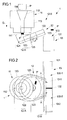
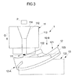
- Fig. 1 to Fig. 3 show schematic views of a compacting 1 with a sorting device 12. Die Fig. 1 returns a side view that Fig. 2 a view from above and the Fig. 3 an isometric view. Below is on all Fig. 1 to Fig. 3 Reference is made to describe firstly the compacting plant 1 with the sorting device 12 and secondly a method for operating the sorting device 12.
- the compacting plant 1 has a compacting unit 11, the sorting device 12 and a collecting unit 13.
- Packages P to be compacted for example empty plastic bottles or similar hollow bodies, such as cans, are fed to the compacting unit 11 at an input 114, either manually or automatically.
- the compacting unit 11 has a compacting element 112 shown only schematically in the figures, which compacts the input non-compacted container P to output it at an output 111 of the compacting unit 11 as a compacted container P '.
- the compacting element 112 is arranged, for example, within a housing 113 of the compacting unit 11.
- the collecting device 12 is arranged below the output 111 of the compacting unit 11.
- the arrangement of the collecting device 12 below the outlet 111 has the advantage that the compacted container P 'falls into the collecting device 12 due to gravity acting in the direction of gravity G, that is, automatically fed to the collecting device 12 without any means being provided for it have to.
- the sorter 12 is roughly subdivided into a catchment area 12-A which serves to catch the compacted can P 'and an ejection area 12-B which serves to feed the compacted can P' to the collection unit 13.
- the collecting unit 13 has a housing 131 in which a first collecting container 13-1 and a second collecting container 13-2 are integrated, which are separated from each other by a limiting means 132.
- the collecting unit 13 For entering compacted container P ', the collecting unit 13 has an inlet opening 133, which is divided into a first input 133-1 for the first collecting container 13-1 and a second input 133-2 for the second collecting container 13-2.
- first collecting container 13-1 and the second collecting container 13-2 of the collecting unit 13 compacted container P 'should be collected.
- the first sump 13-1 is for a first type of compacted container
- the second sump 13-2 is for a second type of compacted container. But it is also possible that both containers 13-1 and 13-2 are provided for the same type of compacted container P '.
- the sorting device 12 In order to transport the compacted container P 'from the compacting unit 11 to the collecting unit 13, the sorting device 12 is provided. As in Fig. 1 to Fig. 3 shown schematically, the sorting device 12 is arranged inclined relative to the direction of gravity G, wherein this inclined arrangement of the collecting device 12 is not mandatory. The collecting device 12 could also be arranged approximately perpendicular to the direction of gravity G. However, the inclined arrangement of the collecting device 12 has the advantage that the collecting unit does not necessarily have to be arranged below the ejection region 12-B of the collecting device 12, but in principle can also be positioned so that the inlet opening 133 of the collecting unit 13 above the ejection region 12-B the sorting device 12 is (so different than it is in the Fig. 1 to Fig. 3 is shown).
- the sorting device 12 is designed to accept the compacting unit 11 compacted container P 'of the Kompaktiermaschine 11 and supply it to the collecting unit 13, more precisely: the input port 133 of the collecting unit 13 supply.
- the sorting device 12 has a sorting element 123 rotatable about an axis of rotation R, which is designed to take along the assumed compacted container P 'along a direction of rotation r and to convey the compacted container P' to the collecting unit 13, and that of a drive unit 125, as an electric motor, is driven.
- the rotatable sorting element 123 is configured in the form of a turntable.
- an impeller would come with at least one in relation to the Rotation axis R radially formed wings into consideration, as has been shown in detail in the general part of the description. Below is always from the hub 123 the speech, which - to emphasize again - instead of the turntable and said impeller could be used or any other rotatable about the rotation axis R sorting element, which is suitable for the purposes described below.
- the turntable 123 is arranged approximately perpendicular to the rotation axis R and rotatable about the same. On the one hand, it is possible for the turntable 123 to be rotatable only in one direction about the rotation axis R and, on the other hand, it is possible for the turntable 123 to be rotatable about the rotation axis R in both directions so that the direction of rotation r is thus adjustable.
- the turntable 123 extends into both the catchment area 12-A and the ejection area 12-B of the sorting device 12.
- the turntable 123 forms a catching surface for catching the bundle P 'compacted by the compacting unit 11, which falls into the sorting device 12 due to gravity, in the catching area 12-A.
- the turntable 123 is rotated either clockwise or counterclockwise about the rotation axis R, whereby the collected compacted container P 'is accelerated and taken along the direction of rotation r to the sorter 12 in the ejection region 12-B at a certain speed and a certain Exit direction A or A ', and so is transported to the collecting unit 13.
- a band 122 is provided which is approximately radially symmetrical in the collecting region 12-A with respect to the rotation axis R and in Ejection region 12-B is translational, so as to specify the ejection direction A or A '.
- the band 122 abuts in the radial direction of the hub 123 and takes over in this way the role of a guide element, on the one hand prevents leakage of the compacted container P 'from the sorter 12 in the collecting area 12-A and on the other a directed ejection of the compacted Canned P 'allowed in the ejection region 12-B.
- the band 122 is thus configured approximately horseshoe-shaped and forms in the ejection region 12-B with the translationally extending parts and the recess the ejection opening 121, at which the entrained compacted container P 'leaves the sorting device 12.
- a control unit which is optionally configured to adjust the rotational speed of the turntable 123, adjust the direction of rotation of the turntable 123 and / or modify the position of the ejection opening 121 to the flight distance and / or to influence the direction of flight of the ejected compacted thread P '.
- the control of the sorting device 12 by the control unit (which in Fig. 1 to Fig. 3 not shown), for example, based on measurement data, which detects the control unit by means of a dedicated sensor device.
- the control unit is designed to operate the turntable 123 at intervals, for example, only when actually compacted container P 'has been entered into the sorting device 12.
- control unit determines the type of compacted container P 'and varies or adjusts the rotational speed and / or the direction of rotation and / or the position of the ejection opening 121 as a function of the determined type. For example, the control unit rotates the entire sorting device 12 about the rotation axis R by a certain angle, so that the ejection opening 121 selectively points to the first collection container 13-1 or to the second collection container 13-2.
- the control unit varies the direction of rotation and / or the rotational speed of the turntable 123 corresponding, for example, sequentially or randomly, always ensuring that the ejected compacted container P 'is always conveyed to the input port 133 of the collecting unit 13.
- the band 122 at least in the Ejection region 12-B is configured controllable by, for example, by a corresponding adjustable angling the transversely extending band in this area 12-B, the ejection direction A or A 'is varied.
- an outlet 124 is also provided at the sorting device 12, via which liquid collected in the sorting device 12 can be deposited. It often happens that a certain residual liquid is present in the non-compacted thread P, so that not only the compacted container P 'reaches the sorting device 12 via the outlet 111 of the compacting unit 11, but also undesired residual liquid which impedes the operation of the sorting device 12 can negatively influence.
- said outlet 124 is provided, which is for example simply formed by a corresponding recess in the band 122 in the collecting area 12-A. Due to the inclined arrangement of the sorting device 12, the liquid collected in the sorting device 12 automatically leaves the sorting device 12 via the outlet 124. Below the outlet 124, a collecting container for collecting the separated liquid can be provided.
- the use of the sorting device 12 within the compacting 1 allows the formation of a compact compacting 1, since the transport of the compacted container P 'by entrainment by means of the sorting element 123 within the sorter 12 along the belt 122 both height differences between the output 111 of the Kompaktierech 11 and the Input opening 133 of the collecting unit 13 as well as by changing the direction of rotation, the sorting can be done in several containers 13-1 and 13-2.
- the compacting downstream sorting also allows a compact access protection against the output 111 of the Kompaktierü 11. This makes it possible, for example, the collecting container 13-1 and 13-2 of the collecting unit 13 to replace even during operation of the compacting 1. As long as the sorting device 12 ejects no compacted container P ', the sorting device 12 thus acts as a buffer for compacted container P'.
- the collecting unit 13 is not only arranged on one side of the sorting device 12, but surrounds the same approximately circular, so that the collecting unit 13 may have a relatively large collecting volume. Characterized in that the position of the ejection opening 121 of the sorting device 12 is modifiable, so for example also completely around the rotation axis R. is rotatable, each area of the collecting unit 13 can be operated by the sorting device 12.
- the sorting device 12 is always shown in an inclined arrangement in which the axis of rotation R intersects the direction of gravity G at an angle of approximately 30 °. But it is also possible to arrange the sorting device 12 at a different angle of inclination, in particular also such that the rotation axis R is substantially parallel to the direction of gravity G, the collecting surface formed by the turntable 123 for collecting the compacted container P 'thus substantially perpendicular to Gravity direction G and thus lies in the horizontal.
Landscapes
- Engineering & Computer Science (AREA)
- Mechanical Engineering (AREA)
- Sorting Of Articles (AREA)
- Combined Means For Separation Of Solids (AREA)
Abstract
Description
- Die vorliegende Erfindung betrifft eine Sortiervorrichtung für eine Kompaktieranlage gemäß dem Oberbegriff des Patentanspruchs 1 sowie ein Verfahren zum Betreiben einer Sortiervorrichtung für eine Kompaktieranlage gemäß dem Oberbegriff des Patentanspruchs 15.
- Eine gattungsgemäße Kompaktieranlage umfasst eine Kompaktiereinheit, die an einem Eingang nicht-kompaktiertes Gebinde entgegennimmt und an einem Ausgang kompaktiertes Gebinde ausgibt, sowie eine Sammeleinheit zum Sammeln von kompaktierten Gebinden. Gelegentlich wird zwischen der Sammeleinheit und der Kompaktiereinheit eine Sortiervorrichtung angeordnet, die das von der Kompaktiereinheit kompaktierte Gebinde annimmt und der Sammeleinheit zuführt. Beispielsweise weist eine derartige Sammeleinheit verschiedene Sammelbehälter auf und die Sortiervorrichtung ist ausgebildet, das von ihr angenommene kompaktierte Gebinde wahlweise einem der verschiedenen Behälter des Sammeleinheit zuzuführen.
- Eine gattungsgemäße Sortiervorrichtung ist beispielsweise aus der
US 4,373,435 bekannt, wo die Sortiervorrichtung in Form einer schrägen Ebene ausgebildet ist, die an ihrem Boden eine Öffnung aufweist, die über ein bewegliches Element selektiv geöffnet oder verschlossen werden kann. - Die
US 5,167,184 beschreibt eine weitere gattungsgemäße Sortiervorrichtung. Dabei ist die Sortiervorrichtung in Gestalt eines Förderbands ausgestaltet. Von der Kompaktiereinheit kompaktiertes Gebinde fällt auf dieses Förderband und wird von dem Förderband in translatorischer (geradliniger) Richtung zur Sammeleinheit befördert. - Aufgabe der vorliegenden Erfindung ist es, eine Sortiervorrichtung für eine Kompaktieranlage bzw. ein Verfahren zum Betreiben einer Sortiervorrichtung für eine Kompaktieranlage vorzuschlagen, die bzw. das eine kompakte Bauform der Kompaktieranlage erlaubt.
- Gelöst wird diese Aufgabe durch einen Gegenstand gemäß einem der unabhängigen Patentansprüche 1 und 15. Merkmale vorteilhafter Ausführungsformen sind in den Unteransprüchen vorgesehen.
- Die erfindungsgemäße Sortiervorrichtung des ersten Aspektes der vorliegenden Erfindung weist ein um eine Rotationsachse drehbares Sortierelement auf, das ausgebildet ist zum Mitnehmen des angenommenen kompaktierten Gebindes entlang einer Drehrichtung um die Rotationsachse und zum Befördern des kompaktierten Gebindes hin zur Sammeleinheit.
- Das Sortierelement, das beispielsweise in Gestalt einer Drehscheibe und/oder in Gestalt eines Flügelrades mit wenigstens einem in Bezug auf die Rotationsachse radial ausgebildeten Flügel ausgebildet ist, nimmt das angenommene kompaktierte Gebinde also entlang der Drehrichtung um die Rotationsachse mit und befördert es aufgrund dieser Drehbewegung hin zur Sammeleinheit der Kompaktieranlage.
- Aufgrund des um die Rotationsachse drehbaren Sortierelements ist es einerseits insbesondere möglich, die Sortiervorrichtung unterhalb der Kompaktiereinheit anzuordnen, sodass von der Kompaktiereinheit kompaktiertes Gebinde aufgrund der Schwerkraftwirkung in die Sortiervorrichtung fallen kann, und andererseits jedoch nicht notwendig, die Sammeleinheit unterhalb der Sortiervorrichtung anzuordnen. Vielmehr erlaubt der Einsatz des drehbaren Sortierelements gemäß vorteilhafter Ausführungsformen ein Auswerfen des angenommenen kompaktierten Gebindes auch wenigstens teilweise entgegen der Schwerkraft, sodass eine Eingangsöffnung der Sammeleinheit auf gleicher Höhe zur Sortiervorrichtung oder sogar oberhalb der Sortiervorrichtung positioniert sein kann. Dadurch ist es insgesamt möglich, insbesondere die Bauhöhe der Kompaktieranlage zu verringern, wodurch die Benutzerfreundlichkeit der Kompaktieranlage erhöht wird. Beispielsweise ist es mitunter erforderlich, dass ein Eingang der Kompaktiereinheit zum Eingeben von nicht kompaktierten Gebinden nicht oberhalb einer vorbestimmten Höhe von beispielsweise 1 bis 1,5 Meter liegt. Derartige Vorgaben können aufgrund des Einsatzes der Sortiervorrichtung nunmehr leichter eingehalten werden, da es insbesondere nicht erforderlich ist, dass die Sammeleinheit unterhalb der Sortiervorrichtung angeordnet wird.
- Nachfolgend werden weitere bevorzugte Ausführungsformen der Sortiervorrichtung des ersten Aspektes der vorliegenden Erfindung erläutert. Die weiteren Merkmale dieser weiteren Ausführungsformen können miteinander als auch mit den bereits oben beschriebenen optionalen Merkmalen zum Ausbilden weiterer Ausführungsbeispiele kombiniert werden, sofern sie nicht ausdrücklich als alternativ zueinander beschrieben sind.
- Beispielsweise ist die Sortiervorrichtung für einen Einsatz in einer Kompaktieranlage ausgestaltet. Die Kompaktieranlage umfasst wenigstens eine Kompaktiereinheit, die ausgebildet ist, nicht-kompaktiertes Gebinde, wie beispielsweise Plastikflaschen, Glasflaschen, Dosen, andere Hohlkörper oder anderes zu kompaktierendes oder zu zerkleinerndes Gebinde, an einem Eingang der Kompaktiereinheit entgegenzunehmen. Das nicht-kompaktierte Gebinde kann der Kompaktiereinheit entweder manuell oder automatisch durch entsprechende Mittel zugeführt werden. Die Kompaktiereinheit kompaktiert oder zerkleinert das entgegengenommene nicht-kompaktierte Gebinde und gibt an einem Ausgang der Kompaktiereinheit das kompaktierte Gebinde aus. Zum Kompaktieren von Gebinden umfasst die Kompaktiereinheit beispielsweise eine Walze, eine Presse oder ähnliche Mittel zum Kompaktieren von Gebinden. Auf die genaue Ausgestaltung der Kompaktiereinheit kommt es vorliegend weniger an. Insbesondere ist die Sortiervorrichtung nicht nur für eine Anwendung in einer Kompaktieranlage geeignet, sondern kann grundsätzlich auch in anderen Materialverarbeitungsanlagen eingesetzt werden, bei denen eine Sortierung von Materialstücken zweckmäßig ist.
- Die Sortiervorrichtung ist beispielsweise ausgebildet, dass an einem Ausgang der Kompaktiereinheit ausgegebene kompaktierte Gebinde anzunehmen. Für diese Zwecke ist die Sortiervorrichtung beispielsweise unterhalb des Ausgangs der Kompaktiereinheit angeordnet, sodass das am Ausgang der Kompaktiereinheit ausgegebene kompaktierte Gebinde aufgrund der Schwerkraftwirkung in die Sortiervorrichtung bzw. auf die Sortiervorrichtung fällt.
- Das Sortierelement der Sortiervorrichtung ist um die Rotationsachse drehbar gelagert und ausgebildet, das angenommene kompaktierte Gebinde entlang der Drehrichtung um die Rotationsachse mitzunehmen, beispielsweise entlang der Drehrichtung zu beschleunigen, und das kompaktierte Gebinde so hin zur Sammeleinheit der Kompaktieranlage zu befördern. Das mitgenommene kompaktierte Gebinde erfährt demnach insbesondere eine rotatorische Bewegung und nicht nur eine rein translatorische.
- Wie oben bereits erläutert worden ist, ist das Sortierelement beispielsweise in Gestalt einer Drehscheibe ausgestaltet, die um die Drehachse drehbar angeordnet ist. Alternativ oder zusätzlich dazu ist ein um die Drehachse drehbares Flügelrad vorgesehen, das wenigstens einen in Bezug auf die Rotationsachse radial ausgebildeten Flügel aufweist, um mit diesem am angenommenen kompaktierten Gebinde anzugreifen und dieses entlang der Drehrichtung um die Rotationsachse zur Sammeleinheit zu befördern.
- Ist die Sortiervorrichtung für eine Anordnung unterhalb der Kompaktiereinheit der Kompaktieranlage ausgestaltet, so ist es ferner bevorzugt, dass die Sortiervorrichtung zum Auffangen des kompaktierten Gebindes eine Auffangfläche aufweist, die bevorzugt im Wesentlichen senkrecht zur Rotationsachse angeordnet ist. Bei der Ausführungsform, bei der das Sortierelement besagte Drehscheibe aufweist, wird diese Auffangfläche bevorzugt durch die Oberfläche der Drehscheibe selbst ausgebildet. Mit anderen Worten, fällt bei dieser Ausführungsform von der Kompaktiereinheit kompaktiertes Gebinde auf die Oberfläche der Drehscheibe (Auffangfläche) und wird von der Drehscheibe um die Rotationsachse beschleunigt und so hin zur Sammeleinheit befördert. Wenn anstelle der Drehscheibe das besagte Flügelrad vorgesehen ist, so ist die Auffangfläche beispielsweise gebildet durch einen senkrecht zur Rotationsachse angeordnete Platte, und der wenigstens eine Flügel des Flügelrads ist oberhalb der Platte drehbar um die Rotationsachse angeordnet, um so das aufgefangene kompaktierte Gebinde über die Platte entlang der Drehrichtung um die Rotationsachse hin zur Sammeleinheit zu befördern.
- Bei einer weiteren bevorzugten Ausführungsform weist die Sortiervorrichtung eine in Bezug auf die Rotationsachse wenigstens teilweise radialsymmetrisch ausgestaltete und an das Sortierelement radial angrenzende Bande auf, die ausgebildet ist, das vom Sortierelement entlang der Drehrichtung um die Rotationsachse mitgenommene kompaktierte Gebinde innerhalb der Sortiervorrichtung zu führen. Die Bande ist also bevorzugt derart ausgestaltet, dass sie ein unerwünschtes Austreten des von dem Sortierelement mitgenommenen kompaktierten Gebindes verhindert. Wird das kompaktierte Gebinde also durch das Sortierelement entlang einer Drehrichtung um die Rotationsachse beschleunigt, so führen die dadurch erzeugten, auf das kompaktierte Gebinde wirkende Fliehkräfte nicht dazu, dass das kompaktierte Gebinde die Sortiervorrichtung an einer unerwünschten Stelle verlässt.
- Bei einer weiteren bevorzugten Ausführungsform der Sortiervorrichtung ist das Sortierelement ausgebildet, das kompaktierte Gebinde an einer Auswurföffnung der Sortiervorrichtung auszuwerfen, um das kompaktierte Gebinde hin zur Sammeleinheit zu befördern. Beispielsweise ist die Auswurföffnung gebildet durch eine Aussparung in der Bande. Beispielsweise ist also die Bande hufeisenförmig ausgestaltet, beispielsweise in einem Auffangbereich der Sortiervorrichtung etwa radialsymmetrisch zur Rotationsachse und in einem Auswurfbereich der Sortiervorrichtung etwa translatorisch verlaufend, um die Auswurföffnung auszubilden. Die Abmessungen der Auswurföffnung sind bevorzugt an die Abmessungen des kompaktierten Gebindes angepasst.
- An dieser Stelle sei in Bezug auf eine bevorzugte räumlich-körperliche Ausgestaltung der Sortiervorrichtung angemerkt, dass bevorzugt ist, dass die Rotationsachse wahlweise etwa parallel zur Schwerkraftrichtung liegt oder die Schwerkraftrichtung in einem Winkel schneidet, der zwischen 0° und 70°, bevorzugt zwischen 0° und 30° liegt. Dabei ist es stets bevorzugt, dass die Auffangfläche der Sortiervorrichtung im Wesentlichen senkrecht zu dieser Rotationsachse angeordnet ist. Liegt die Rotationsachse parallel zur Schwerkraftrichtung, so erfolgt der Auswurf des kompaktierten Gebindes in etwa parallel zur Horizontalen; bei einem Schnittwinkel von über 0° erfolgt der Auswurf des kompaktierten Gebindes wenigstens teilweise gegen die Schwerkraftrichtung. Liegt der Schnittwinkel beispielsweise bei 15°, so erfolgt der Auswurf des kompaktierten Gebindes etwa in einem Winkel von 15° über der Horizontalen und damit gegen die Schwerkraftrichtung.
- Demnach ist bei einer bevorzugten Ausführungsform der Sortiervorrichtung vorgesehen, dass die Sortiervorrichtung für eine gegenüber der Schwerkraftrichtung geneigte Anordnung ausgestaltet ist. Beispielsweise schneidet also die Schwerkraftrichtung die Auffangfläche der Sortiervorrichtung in einem Winkel von weniger als 90°, beispielsweise bei einem Winkel zwischen 90° und 60°. Mit anderen Worten, ist es bevorzugt, dass die Rotationsachse die Schwerkraftrichtung beispielsweise in einem Winkel zwischen 0° und 30° schneidet.
- Bei einer weiteren bevorzugten Ausführungsform der Sortiervorrichtung weist die Sortiervorrichtung einen Auslass auf, um eine in der Sortiervorrichtung gesammelte Flüssigkeit auszulassen. Häufig ist in dem zu kompaktierenden Gebinde noch eine Restflüssigkeit enthalten, die gelegentlich bei der Kompaktierung des Gebindes nicht entweicht. Daher kann sich in der Sortiervorrichtung, die das kompaktierte Gebinde von der Kompaktiereinheit annimmt, bei laufendem Betrieb Flüssigkeit sammeln, wobei es zweckmäßig ist, diese Flüssigkeit aus der Sortiervorrichtung zu entfernen, um einen dauerhaften Betrieb der Kompaktieranlage gewährleisten zu können. Für diese Zwecke ist besagter Auslass vorgesehen. Der Auslass ist beispielsweise in Gestalt einer weiteren Aussparung in der besagten Bande ausgebildet, sodass bei geneigter Anordnung der Sortiervorrichtung die Flüssigkeit in der Sortiervorrichtung aufgrund der Schwerkraftwirkung die Sortiervorrichtung selbsttätig verlässt und beispielsweise in einen dafür vorgesehenen Auffangbehälter fließt. Aufgrund der Ausgestaltung der Sortiervorrichtung erfordert dieser zusätzliche Auffangbehälter kaum zusätzlichen Bauraum, da es - wie oben ausführlich dargestellt - nicht notwendig ist, die Sammeleinheit unterhalb der Sortiervorrichtung zu positionieren, sodass unterhalb der Sortiervorrichtung noch Raum für besagten Auffangbehälter zum Auffangen der Flüssigkeit verbleibt.
- Bei einer noch weiteren bevorzugten Ausführungsform der Sortiervorrichtung umfasst die Sortiervorrichtung eine Steuereinheit zum Betreiben des Sortierelements, wobei die Steuereinheit bevorzugt ausgebildet ist, die Drehrichtung und/oder die Drehfrequenz des Sortierelements zu steuern. Diese Variante erlaubt eine Beeinflussung der Flugbahn eines von der Sortiervorrichtung ausgeworfenen kompaktierten Gebindes.
- Zunächst ist durch die Wahl der Drehrichtung und durch die entsprechende Ausgestaltung der Auswurföffnung eine Richtung einstellbar, in der das ausgeworfene kompaktierte Gebinde die Sortiervorrichtung verlässt. Dadurch ist es möglich, das kompaktierte Gebinde gezielt in der Sammeleinheit der Kompaktieranlage zu positionieren, beispielsweise in verschiedenen Containern der Sammeleinheit und/oder in verschiedenen Bereichen der Sammeleinheit. So kann beispielsweise sichergestellt werden, dass in der Sammeleinheit keine Schüttkegel von kompaktierten Gebinden entstehen, sondern vielmehr, dass die kompaktierten Gebinde gleichmäßig in der Sammeleinheit verteilt werden.
- Durch Einstellung der Drehgeschwindigkeit kann insbesondere die Flugweite des ausgeworfenen kompaktierten Gebindes eingestellt werden und auf diese Weise ebenfalls sichergestellt werden, dass das kompaktierte Gebinde an angemessener Stelle innerhalb der Sammeleinheit landet. An dieser Stelle sei angemerkt, dass der Gegenstand der vorliegenden Erfindung nicht erfordert, dass das Sortierelement eine vollständige Umdrehung um die Rotationsachse beschreibt. Vielmehr kann es zum Auswerfen des kompaktierten Gebindes ausreichend sein, dass das Sortierelement, beispielsweise eine Drehscheibe und/oder ein Flügelrad mit wenigstens einem Flügel, um einen bestimmten Winkelbereich von einigen Grad, beispielsweise um 5° oder um 60°, um die Rotationsachse gedreht wird, um das kompaktierte Gebinde entlang der Drehrichtung mitzunehmen und dieses zur Sammeleinheit zu befördern. Beispielsweise ist also die Steuereinheit ausgebildet, das Sortierelement impulsartig um einen bestimmten Winkelbereich um die Rotationsachse zu beschleunigen, um das mitgenommene kompaktierte Gebinde zur Sammeleinheit zu befördern.
- Bei einer weiteren bevorzugten Ausführungsform der Sortiervorrichtung ist besagte Steuereinheit ausgebildet, das Sortierelement intervallmäßig um die Rotationsachse zu drehen. Der Gegenstand der vorliegenden Erfindung erfordert also nicht etwa einen kontinuierlichen Betrieb des Sortierelements, sondern die Steuereinheit kann vielmehr sicherstellen, dass das Sortierelement belastungsabhängig, also in Anhängigkeit von dem der Sortiervorrichtung zugeführten kompaktierten Gebinden, gesteuert wird.
- Um das Sortierelement anzutreiben und/oder zum die Auswurföffnung einzustellen kann eine Antriebseinheit vorgesehen sein, beispielsweise ein oder mehrere Elektromotoren.
- Zur Lösung der oben stehenden technischen Aufgabe wird erfindungsgemäß ferner eine Kompaktieranlage vorgeschlagen, die eine Kompaktiereinheit zum Kompaktieren von Gebinden und eine Sammeleinheit zum Sammeln von kompaktierten Gebinden aufweist und dadurch gekennzeichnet ist, dass die Kompaktieranlage eine zwischen der Kompaktiereinheit und der Sammeleinheit angeordnete Sortiervorrichtung umfasst, wie sie vorstehend in verschiedenen Ausführungsformen beschrieben worden ist. Selbstverständlich teilt die erfindungsgemäße Kompaktieranlage die Vorteile der eben beschriebenen Sortiervorrichtung und weist bevorzugte Ausführungsformen auf, die den oben beschriebenen bevorzugten Ausführungsformen der Sortiervorrichtung entsprechen, insbesondere, wie sie in den abhängigen Ansprüchen definiert sind. Insoweit wird auf das Vorstehende verwiesen.
- Es ist also beispielsweise bevorzugt, dass die Sortiervorrichtung unterhalb eines Ausgangs der Kompaktiereinheit, an welchem die Kompaktiereinheit kompaktiertes Gebinde ausgibt, angeordnet ist. Beispielsweise weist die Sammeleinheit der Kompaktieranlage wenigstens zwei Sammelbehälter auf, und die Sortiervorrichtung ist ausgebildet, das mitgenommene kompaktierte Gebinde wahlweise einem der wenigstens zwei Sammelbehälter zuzuführen. Auch dies wurde bereits oben mit Bezug auf die Steuereinheit, die ausgebildet ist, die Drehrichtung und/oder die Drehgeschwindigkeit zu steuern, erläutert.
- Um die Wartbarkeit der Sortiervorrichtung bzw. der Kompaktieranlage zu vereinfachen, ist bei einer bevorzugten Ausführungsform vorgesehen, dass die Sortiervorrichtung gegen die Rotationsachse schwenkbar angeordnet ist. Einer Servicekraft wird so ermöglicht, schnell und einfach Zugang zur Sortiervorrichtung zu erhalten, sodass beispielsweise das Sortierelement ausgetauscht oder repariert werden kann und/oder andere Handlungen zur Entstörung vorgenommen werden können. Die Schwenkbarkeit gegen die Rotationsachse verbessert nicht nur die Zugänglichkeit, sondern erlaubt darüber hinaus auch eine noch weitere Beeinflussung der Flugbahn des ausgeworfenen kompaktierten Gebindes. Besagte Steuereinheit ist bevorzugt nicht nur ausgebildet, die Drehrichtung, die Drehgeschwindigkeit und/oder die Position der Auswurföffnung einzustellen, sondern auch den Schwenkwinkel gegen die Rotationsachse, um für das zur Sammeleinheit zu befördernde kompaktierte Gebinde die richtige Flugbahn festzulegen, sodass das ausgeworfene kompaktierte Gebinde an der gewünschten Position innerhalb der Sammeleinheit landet.
- Einen zweiten Aspekt der vorliegenden Erfindung bildet das Verfahren gemäß dem unabhängigen Patentanspruch 15. Auch das Verfahren des zweiten Aspektes der vorliegenden Erfindung teilt die Vorteile der Sortiervorrichtung des ersten Aspektes der vorliegenden Erfindung und weist bevorzugte Ausführungsformen auf, die den oben beschriebenen bevorzugten Ausführungsformen der Sortiervorrichtung bzw. der Kompaktieranlage entsprechen, insbesondere, wie sie in den abhängigen Ansprüchen definiert sind. Insoweit wird auf das Vorstehende verwiesen.
- Der der Erfindung zugrunde liegende Gedanke soll nachfolgend anhand der in den Figuren dargestellten Ausführungsbeispiele näher erläutert werden. Es zeigen:
- Fig. 1
- eine schematische Seitenansicht einer exemplarischen Kompaktieranlage mit einer exemplarischen Sortiervorrichtung;
- Fig. 2
- die in der
Fig. 1 gezeigte exemplarische Kompaktieranlage mit der exemplarischen Sortiervorrichtung in einer schematischen Ansicht von oben; und - Fig. 3
- die in der
Fig. 1 und in derFig. 2 gezeigte exemplarische Kompaktieranlage mit der exemplarischen Sortiervorrichtung in einer schematischen isometrischen Ansicht. - Die
Fig. 1 bis Fig. 3 zeigen schematische Ansichten eine Kompaktieranlage 1 mit einer Sortiervorrichtung 12. DieFig. 1 gibt eine Seitenansicht wieder, dieFig. 2 eine Ansicht von oben und dieFig. 3 eine isometrische Ansicht. Nachfolgend wird auf sämtlicheFig. 1 bis Fig. 3 Bezug genommen, um zum einen die Kompaktieranlage 1 mit der Sortiervorrichtung 12 und zum anderen ein Verfahren zum Betreiben der Sortiervorrichtung 12 zu beschreiben. - Die Kompaktieranlage 1 weist eine Kompaktiereinheit 11, die Sortiervorrichtung 12 und eine Sammeleinheit 13 auf. Zu kompaktierendes Gebinde P, beispielsweise leere Plastikflaschen oder ähnliche Hohlkörper, wie beispielsweise Dosen, werden der Kompaktiereinheit 11 an einem Eingang 114 wahlweise manuell oder automatisch zugeführt. Zum Kompaktieren des nicht-kompaktierten Gebindes P weist die Kompaktiereinheit 11 ein in den Figuren lediglich schematisch dargestelltes Kompaktierelement 112 auf, das das eingegebene nicht-kompaktierte Gebinde P kompaktiert, um es an einem Ausgang 111 der Kompaktiereinheit 11 als kompaktiertes Gebinde P' auszugeben. Das Kompaktierelement 112 ist beispielsweise innerhalb eines Gehäuses 113 der Kompaktiereinheit 11 angeordnet.
- Unterhalb des Ausgangs 111 der Kompaktiereinheit 11 ist die Sammelvorrichtung 12 angeordnet. Die Anordnung der Sammelvorrichtung 12 unterhalb des Ausgangs 111 hat den Vorteil, dass das kompaktierte Gebinde P' aufgrund der Schwerkraft, die in Schwerkraftrichtung G wirkt, in die Sammelvorrichtung 12 fällt, der Sammelvorrichtung 12 also automatisch zugeführt wird, ohne dass dafür irgendwelche Mittel bereitgestellt werden müssen. Die Sortiervorrichtung 12 lässt sich grob unterteilen in einen Auffangbereich 12-A, der dem Auffangen des kompaktierten Gebindes P' dient, und einem Auswurfbereich 12-B, der dem Zuführen des kompaktierten Gebindes P' zu der Sammeleinheit 13 dient.
- Die Sammeleinheit 13 weist ein Gehäuse 131 auf, in welchem ein erster Sammelbehälter 13-1 und ein zweiter Sammelbehälter 13-2 integriert sind, die durch ein Begrenzungsmittel 132 voneinander getrennt sind.. Zum Eingeben von kompaktierten Gebinde P' weist die Sammeleinheit 13 eine Eingangsöffnung 133 auf, die sich in einem ersten Eingang 133-1 für den ersten Sammelbehälter 13-1 und einen zweiten Eingang 133-2 für den zweiten Sammelbehälter 13-2 unterteilt. Innerhalb des ersten Sammelbehälters 13-1 und des zweiten Sammelbehälters 13-2 der Sammeleinheit 13 soll kompaktiertes Gebinde P' gesammelt werden. Beispielsweise ist der erste Sammelbehälter 13-1 für einen ersten Typ von kompaktierten Gebinde vorgesehen und der zweite Sammelbehälter 13-2 für einen zweiten Typ von diesem kompaktierten Gebinde. Es ist aber auch möglich, dass beide Behälter 13-1 und 13-2 für denselben Typ von kompaktierten Gebinde P' vorgesehen sind.
- Um das kompaktierte Gebinde P' also von der Kompaktiereinheit 11 hin zur Sammeleinheit 13 zu befördern, ist die Sortiervorrichtung 12 vorgesehen. Wie in
Fig. 1 bis Fig. 3 schematisch dargestellt, ist die Sortiervorrichtung 12 gegenüber der Schwerkraftrichtung G geneigt angeordnet, wobei diese geneigte Anordnung der Sammelvorrichtung 12 nicht zwingend erforderlich ist. Die Sammelvorrichtung 12 könnte auch in etwa senkrecht zur Schwerkraftrichtung G angeordnet sein. Die geneigte Anordnung der Sammelvorrichtung 12 hat jedoch den Vorteil, dass die Sammeleinheit nicht notwendigerweise unterhalb des Auswurfbereichs 12-B der Sammelvorrichtung 12 angeordnet sein muss, sondern grundsätzlich auch so positioniert sein kann, dass die Eingangsöffnung 133 der Sammeleinheit 13 oberhalb des Auswurfsbereichs 12-B der Sortiervorrichtung 12 liegt (also anders, als es in denFig. 1 bis Fig. 3 dargestellt ist). - Nachfolgend soll etwas näher auf die Ausgestaltung der Sortiervorrichtung 12 eingegangen werden. Grundsätzlich ist die Sortiervorrichtung 12 ausgebildet, das von der Kompaktiereinheit 11 kompaktierte Gebinde P' von der Kompaktiereinheit 11 anzunehmen und dieses der Sammeleinheit 13 zuzuführen, genauer also: der Eingangsöffnung 133 der Sammeleinheit 13 zuzuführen. Für diese Zwecke weist die Sortiervorrichtung 12 ein um eine Rotationsachse R drehbares Sortierelement 123 auf, das ausgebildet ist zum Mitnehmen des angenommenen kompaktierten Gebindes P' entlang einer Drehrichtung r und zum Befördern des kompaktierten Gebindes P' hin zur Sammeleinheit 13, und das von einer Antriebseinheit 125, wie ein Elektromotor, angetrieben wird. Bei dem in dem
Fig. 1 bis 3 gezeigten Ausführungsbeispiel ist das drehbare Sortierelement 123 in Gestalt einer Drehscheibe ausgestaltet. Alternativ oder zusätzlich dazu käme ein Flügelrad mit wenigstens einem in Bezug auf die Rotationsachse R radial ausgebildeten Flügel in Betracht, wie es oben im allgemeinen Teil der Beschreibung ausführlich dargestellt worden ist. Nachfolgend ist stets von der Drehscheibe 123 die Rede, wobei - um dies noch einmal zu betonen - anstelle der Drehscheibe auch besagtes Flügelrad eingesetzt werden könnte oder ein sonstiges um die Rotationsachse R drehbares Sortierelement, das für die nachfolgend geschilderten Zwecke geeignet ist. - Die Drehscheibe 123 ist in etwa senkrecht zur Rotationsachse R angeordnet und um selbige drehbar. Zum einen ist es möglich, dass die Drehscheibe 123 lediglich in eine Richtung um die Rotationsachse R drehbar ist und zum anderen ist es möglich, dass die Drehscheibe 123 in beide Richtungen um die Rotationsachse R drehbar ist, dass die Drehrichtung r also einstellbar ist. Die Drehscheibe 123 erstreckt sich sowohl in den Auffangbereich 12-A als auch in den Auswurfbereich 12-B der Sortiervorrichtung 12.
- Die Drehscheibe 123 bildet eine Auffangfläche aus, um das von der Kompaktiereinheit 11 kompaktierte Gebinde P', das aufgrund der Schwerkraftwirkung in die Sortiervorrichtung 12 fällt, im Auffangbereich 12-A aufzufangen. Die Drehscheibe 123 wird entweder im Uhrzeigersinn oder gegen den Uhrzeigersinn um die Rotationsachse R gedreht, wodurch das aufgefangene kompaktierte Gebinde P' beschleunigt wird und entlang der Drehrichtung r mitgenommen wird, um die Sortiervorrichtung 12 im Auswurfbereich 12-B mit einer bestimmten Geschwindigkeit und einer bestimmten Auswurfrichtung A oder A' zu verlassen, und so zur Sammeleinheit 13 befördert wird.
- Um zu verhindern, dass das kompaktierte Gebinde P' während des Mitnehmens durch die Drehscheibe 123 die Sortiervorrichtung 12 vorzeitig an unerwünschter Stelle verlässt, ist eine Bande 122 vorgesehen, die im Auffangbereich 12-A in Bezug auf die Rotationsachse R etwa radialsymmetrisch ausgestaltet ist und im Auswurfbereich 12-B translatorisch verläuft, um so die Auswurfrichtung A bzw. A' vorzugeben. Die Bande 122 grenzt in radialer Richtung an die Drehscheibe 123 an und übernimmt in dieser Weise die Rolle eines Führungselements, das zum einen ein Austreten des kompaktierten Gebindes P' aus der Sortiervorrichtung 12 im Auffangbereich 12-A verhindert und zum anderen ein gerichtetes Auswerfen des kompaktierten Gebindes P' im Auswurfbereich 12-B erlaubt. Aufgrund der Aussparung in der Bande 122 entsteht im Auswurfbereich 12-B eine Art Auswurframpe, über die das mitgenommene kompaktierte Gebinde P' ausgeworfen wird. Wird die Drehscheibe 123 im Uhrzeigersinn um die Rotationsachse R gedreht, so ergibt sich die Auswurfrichtung A. Wird die Drehscheibe 123 indes gegen den Uhrzeigersinn um die Rotationsachse R gedreht, so verlässt das kompaktierte Gebinde P' die Sortiervorrichtung 12 entlang der Auswurfrichtung A'. Anhand dieser Darstellung wurde bereits veranschaulicht, dass durch die Wahl der Drehrichtung die Auswurfrichtung vorgegeben wird, und damit auch eine Landeposition, an der das ausgeworfene kompaktierte Gebinde P' in der Sammeleinheit 13 landet.
- Bei dem in den
Fig. 1 bis Fig. 3 gezeigten Ausführungsbeispiel ist die Bande 122 demnach etwa hufeisenförmig ausgestaltet und bildet im Auswurfbereich 12-B mit den translatorisch verlaufenden Teilen und der Aussparung die Auswurföffnung 121 aus, an der das mitgenommene kompaktierte Gebinde P' die Sortiervorrichtung 12 verlässt. - Zur Beeinflussung der Flugbahn des ausgeworfenen kompaktierten Gebindes P' kann optional eine Steuereinheit vorgesehen sein, die wahlweise ausgestaltet ist, die Drehgeschwindigkeit der Drehscheibe 123 einzustellen, die Drehrichtung der Drehscheibe 123 einzustellen und/oder die Position der Auswurföffnung 121 zu modifizieren, um die Flugweite und/oder die Flugrichtung des ausgeworfenen kompaktierten Gewindes P' zu beeinflussen. Die Steuerung der Sortiervorrichtung 12 durch die Steuereinheit (die in
Fig. 1 bis Fig. 3 nicht dargestellt ist) kann beispielsweise basierend auf Messdaten erfolgen, die die Steuereinheit mittels einer dafür vorgesehenen Sensoreinrichtung erfasst. Beispielsweise ist die Steuereinheit ausgebildet, die Drehscheibe 123 intervallmäßig zu betreiben, beispielsweise nur dann, wenn tatsächlich kompaktiertes Gebinde P' in die Sortiervorrichtung 12 eingegeben worden ist. Darüber hinaus kann vorgesehen sein, dass die Steuereinheit den Typ des kompaktierten Gebindes P' ermittelt und in Abhängigkeit des ermittelten Typs die Drehgeschwindigkeit und/oder die Drehrichtung und/oder die Position der Auswurföffnung 121 variiert bzw. einstellt. Beispielsweise verdreht die Steuereinheit die gesamte Sortiervorrichtung 12 um die Rotationsachse R um einen bestimmten Winkel, sodass die Auswurföffnung 121 wahlweise zum ersten Sammelbehälter 13-1 oder zum zweiten Sammelbehälter 13-2 weist. Um zu erzielen, dass in den Sammelbehältern 13-1 und 13-2 keine Schüttkegel entstehen, sondern die kompaktierten Gebinde P' dort gleichmäßig verteilt werden, sodass in den Sammelbehältern 13-1 und 13-2 jeweils etwa homogene Füllhöhen entstehen, variiert die Steuereinheit die Drehrichtung und/oder die Drehgeschwindigkeit der Drehscheibe 123 entsprechend, beispielsweise sequentiell oder zufallsmäßig, wobei stets sichergestellt ist, dass das ausgeworfene kompaktierte Gebinde P' stets zur Eingangsöffnung 133 der Sammeleinheit 13 befördert wird. - Anstelle der Modifikation der Position der Auswurföffnung 121 kann gemäß einer optionalen Ausgestaltung auch vorgesehen sein, dass die Bande 122 wenigstens im Auswurfbereich 12-B steuerbar ausgestaltet ist, indem beispielsweise durch eine entsprechende einstellbare Anwinklung der transversal verlaufenden Bande in diesem Bereich 12-B die Auswurfrichtung A bzw. A' variiert wird.
- Optional ist ferner ein Auslass 124 bei der Sortiervorrichtung 12 vorgesehen, über die in der Sortiervorrichtung 12 gesammelte Flüssigkeit abgeschieden werden kann. Häufig kommt es vor, dass in dem nicht-kompaktierten Gewinde P eine gewisse Restflüssigkeit vorhanden ist, sodass über den Ausgang 111 der Kompaktiereinheit 11 nicht nur das kompaktierte Gebinde P' in die Sortiervorrichtung 12 gelangt, sondern auch unerwünschte Restflüssigkeit, die den Betrieb der Sortiervorrichtung 12 negativ beeinflussen kann. Für diese Zwecke ist besagter Auslass 124 vorgesehen, der beispielsweise einfach gebildet ist durch eine entsprechende Aussparung in der Bande 122 im Auffangbereich 12-A. Aufgrund der geneigten Anordnung der Sortiervorrichtung 12 verlässt die in der Sortiervorrichtung 12 gesammelte Flüssigkeit die Sortiervorrichtung 12 selbsttätig über den Auslass 124. Unterhalb des Auslasses 124 kann ein Auffangbehälter zum Auffangen der abgeschiedenen Flüssigkeit vorgesehen sein.
- Der Einsatz der Sortiervorrichtung 12 innerhalb der Kompaktieranlage 1 erlaubt das Ausbilden einer kompakten Kompaktieranlage 1, da der Transport des kompaktierten Gebindes P' durch Mitnahme mittels des Sortierelements 123 innerhalb der Sortiervorrichtung 12 entlang der Bande 122 sowohl Höhenunterschiede zwischen dem Ausgang 111 der Kompaktiereinheit 11 und der Eingangsöffnung 133 der Sammeleinheit 13 als auch durch Änderung der Drehrichtung die Sortierung in mehrere Sammelbehälter 13-1 und 13-2 erfolgen kann. Die der Kompaktierung nachgelagerte Sortierung ermöglicht zudem einen kompakten Zugriffschutz gegenüber dem Ausgang 111 der Kompaktiereinheit 11. Dadurch ist es beispielsweise möglich, die Sammelbehälter 13-1 und 13-2 der Sammeleinheit 13 auch bei laufendem Betrieb der Kompaktieranlage 1 auszutauschen. Solange die Sortiervorrichtung 12 keine kompaktierten Gebinde P' auswirft, fungiert die Sortiervorrichtung 12 also als Zwischenspeicher für kompaktiertes Gebinde P'.
- Darüber hinaus ist es möglich, dass die Sammeleinheit 13 nicht nur an einer Seite der Sortiervorrichtung 12 angeordnet ist, sondern selbige etwa kreisförmig umgibt, sodass die Sammeleinheit 13 ein vergleichsweise großes Sammelvolumen aufweisen kann. Dadurch, dass die Position der Auswurföffnung 121 der Sortiervorrichtung 12 modifizierbar ist, beispielsweise also ebenfalls um die Rotationsachse R vollständig drehbar ist, kann jeder Bereich der Sammeleinheit 13 von der Sortiervorrichtung 12 bedient werden.
- Bei dem in den
Fig. 1 bis Fig. 3 gezeigten Ausführungsbeispiel ist die Sortiervorrichtung 12 stets in einer geneigten Anordnung dargestellt, bei der die Rotationsachse R die Schwerkraftrichtung G in einem Winkel von etwa 30° schneidet. Es ist aber auch möglich, die Sortiervorrichtung 12 in einem anderen Neigungswinkel anzuordnen, insbesondere auch derart, dass die Rotationsachse R im Wesentlichen parallel zur Schwerkraftrichtung G ist, die durch die Drehscheibe 123 gebildete Auffangfläche zum Auffangen des kompaktierten Gebindes P' also im Wesentlichen senkrecht zur Schwerkraftrichtung G und damit in der Horizontalen liegt. -
- 1
- Kompaktieranlage
- 11
- Kompaktiereinheit
- 111
- Ausgang der Kompaktiereinheit 11
- 112
- Kompaktierelement
- 113
- Gehäuse der Kompaktiereinheit 11
- 114
- Eingang der Kompaktiereinheit 11
- 12
- Sortiervorrichtung
- 12-A
- Auffangbereich
- 12-B
- Auswurfbereich
- 121
- Auswurföffnung
- 122
- Bande
- 123
- Sortierelement, z.B. Drehscheibe oder Flügelrad
- 124
- Auslass
- 125
- Antriebseinheit
- 13
- Sammeleinheit
- 13-1
- Erster Sammelbehälter
- 13-2
- Zweiter Sammelbehälter
- 131
- Gehäuse der Sammeleinheit 13
- 132
- Begrenzungsmittel
- 133
- Eingangsöffnung der Sammeleinheit 13
- 133-1
- Erster Eingang des ersten Sammelbehälters 13-1
- 133-2
- Zweiter Eingang des zweiten Sammelbehälters 13-2
- A
- Auswurfrichtung bei Drehung des Sortierelements im Uhrzeigersinn
- A'
- Auswurfrichtung bei Drehung des Sortierelements gegen den Uhrzeigersinn
- R
- Rotationsachse
- r
- Drehrichtung
- G
- Schwerkraftrichtung
- P
- Nicht-kompaktiertes Gebinde
- P'
- Kompaktiertes Gebinde, z.B. Pressling
Claims (15)
- Sortiervorrichtung (12) für eine Kompaktieranlage (1), wobei die Sortiervorrichtung (12) ausgestaltet ist für eine Anordnung zwischen einer Kompaktiereinheit (11) und einer Sammeleinheit (13) der Kompaktieranlage (1) und ausgebildet ist, ein von der Kompaktiereinheit (11) kompaktiertes Gebinde (P') von der Kompaktiereinheit (11) anzunehmen und dieses der Sammeleinheit (13) zuzuführen,
dadurch gekennzeichnet, dass
die Sortiervorrichtung (12) ein um eine Rotationsachse (R) drehbares Sortierelement (123) aufweist, das ausgebildet ist zum Mitnehmen des angenommenen kompaktierten Gebindes (P') entlang einer Drehrichtung (r) um die Rotationsachse (R) und zum Befördern des kompaktierten Gebindes (P') hin zur Sammeleinheit (13). - Sortiervorrichtung (12) nach Anspruch 1, dadurch gekennzeichnet, dass das Sortierelement (123) eine Drehscheibe und/oder ein Flügelrad mit wenigstens einem in Bezug auf die Rotationsachse (R) radial ausgebildeten Flügel aufweist.
- Sortiervorrichtung (12) nach Anspruch 1 oder 2, dadurch gekennzeichnet, dass die Sortiervorrichtung (12) eine in Bezug auf die Rotationsachse (R) wenigstens teilweise radialsymmetrisch ausgestaltete und an das Sortierelement (123) radial angrenzende Bande (122) aufweist, die ausgebildet ist, das vom Sortierelement (123) mitgenommene kompaktierte Gebinde (P') innerhalb der Sortiervorrichtung (12) zu führen.
- Sortiervorrichtung (12) nach einem der vorstehenden Ansprüche, dadurch gekennzeichnet, dass die Sortiervorrichtung (12) einen Auslass (124) aufweist, um eine in der Sortiervorrichtung gesammelte Flüssigkeit auszulassen.
- Sortiervorrichtung (12) nach einem der vorstehenden Ansprüche, dadurch gekennzeichnet, dass die Sortiervorrichtung (12) für eine gegenüber der Schwerkraftrichtung (G), entlang der die Schwerkraft wirkt, geneigte Anordnung ausgestaltet ist.
- Sortiervorrichtung (12) nach Anspruch 1, dadurch gekennzeichnet, dass das Sortierelement (123) ausgebildet ist zum Auswerfen des kompaktierten Gebindes (P') an einer Auswurföffnung (121) der Sortiervorrichtung (12), um das kompaktierte Gebinde hin zur Sammeleinheit (13) zu befördern.
- Sortiervorrichtung (12) nach Anspruch 6, dadurch gekennzeichnet, dass die Position der Auswurföffnung (121) variabel und unabhängig von der Drehung des Sortierelements (123) steuerbar ist.
- Sortiervorrichtung (12) nach einem der vorstehenden Ansprüche, dadurch gekennzeichnet, dass die Sortiervorrichtung (12) eine Steuereinheit zum Betreiben des Sortierelements (123) aufweist, die ausgebildet ist, die Drehrichtung und/oder die Drehgeschwindigkeit des Sortierelements (123) zu steuern.
- Sortiervorrichtung (12) nach Anspruch 8, dadurch gekennzeichnet, dass die Steuereinheit ausgebildet ist, das Sortierelement (123) intervallmäßig um die Rotationsachse (R) zu drehen.
- Sortiervorrichtung (12) nach einem der vorstehenden Ansprüche, dadurch gekennzeichnet, dass die Rotationsachse (R) parallel zur Schwerkraftrichtung (G) liegt oder die Schwerkraftrichtung (G) in einem Winkel schneidet, der zwischen 0° und 70°, bevorzugt zwischen 0° und 30° liegt.
- Sortiervorrichtung (12) nach einem der vorstehenden Ansprüche, dadurch gekennzeichnet, dass die Sortiervorrichtung (12) zum Auffangen des kompaktierten Gebindes (P') eine Auffangfläche aufweist, die im Wesentlichen senkrecht zur Rotationsachse (R) angeordnet ist.
- Kompaktieranlage (1), aufweisend eine Kompaktiereinheit (11) zum Kompaktieren von Gebinde (P) und eine Sammeleinheit (13) zum Sammeln von kompaktierten Gebinde (P'), dadurch gekennzeichnet, dass Kompaktieranlage (1) eine zwischen der Kompaktiereinheit (11) und der Sammeleinheit (13) angeordnete Sortiervorrichtung (12) nach einem der vorstehenden Ansprüche umfasst.
- Kompaktieranlage (1) nach Anspruch 12, dadurch gekennzeichnet, dass die Sortiervorrichtung (12) unterhalb eines Ausgangs (111) der Kompaktiereinheit (11), an welchem die Kompaktiereinheit kompaktiertes Gebinde (P') ausgibt, angeordnet ist.
- Kompaktieranlage (1) nach Anspruch 12 oder 13, dadurch gekennzeichnet, dass die Sammeleinheit (13) wenigstens zwei Sammelbehälter (13-1, 13-2) aufweist und die Sortiervorrichtung (12) ausgebildet ist, das mitgenommene kompaktierte Gebinde (P') wahlweise einem der wenigstens zwei Sammelbehälter (13-1, 13-2) zuzuführen.
- Verfahren zum Betreiben einer Sortiervorrichtung (12) für eine Kompaktieranlage (1), umfassend:- Annehmen eines von einer Kompaktiereinheit (12) der Kompaktieranlage (1) kompaktierten Gebindes (P');- Zuführen des kompaktierten Gebindes (P') zu einer Sammeleinheit (13) der Kompaktieranlage (1)
dadurch gekennzeichnet, dass das Verfahren die folgenden Schritte aufweist:- Mitnehmen des angenommenen kompaktierten Gebindes (P') entlang einer Drehrichtung (r) um eine Rotationsachse (R) mittels eines um die Rotationsachse (R) drehbaren Sortierelements (123) der Sortiervorrichtung (12), um das kompaktierte Gebinde (P') zur Sammeleinheit (13) zu befördern.
Priority Applications (1)
| Application Number | Priority Date | Filing Date | Title |
|---|---|---|---|
| EP14174611.5A EP2960047B1 (de) | 2014-06-26 | 2014-06-26 | Sortiervorrichtung für eine Kompaktieranlage |
Applications Claiming Priority (1)
| Application Number | Priority Date | Filing Date | Title |
|---|---|---|---|
| EP14174611.5A EP2960047B1 (de) | 2014-06-26 | 2014-06-26 | Sortiervorrichtung für eine Kompaktieranlage |
Publications (2)
| Publication Number | Publication Date |
|---|---|
| EP2960047A1 true EP2960047A1 (de) | 2015-12-30 |
| EP2960047B1 EP2960047B1 (de) | 2020-12-09 |
Family
ID=51167610
Family Applications (1)
| Application Number | Title | Priority Date | Filing Date |
|---|---|---|---|
| EP14174611.5A Not-in-force EP2960047B1 (de) | 2014-06-26 | 2014-06-26 | Sortiervorrichtung für eine Kompaktieranlage |
Country Status (1)
| Country | Link |
|---|---|
| EP (1) | EP2960047B1 (de) |
Cited By (2)
| Publication number | Priority date | Publication date | Assignee | Title |
|---|---|---|---|---|
| CN116764972A (zh) * | 2023-07-12 | 2023-09-19 | 中电凯杰科技有限公司 | 一种槟榔分拣机及其分拣方法 |
| CN117840070A (zh) * | 2024-01-31 | 2024-04-09 | 武汉软件工程职业学院(武汉开放大学) | 一种电子元器件的表面缺陷光学检测系统与方法 |
Citations (6)
| Publication number | Priority date | Publication date | Assignee | Title |
|---|---|---|---|---|
| US4373435A (en) | 1981-01-05 | 1983-02-15 | Grevich John J | Crusher and separator for cans and bottles |
| GB2203582A (en) * | 1987-04-16 | 1988-10-19 | Leonard Marmaduke Steele | Coin sorting apparatus |
| US5167184A (en) | 1990-03-01 | 1992-12-01 | Dante Rebecchi | Compacting and selecting machine for solid and ferrous of non-ferrous metallic refuse such as containers, cans, bottles, and similar |
| JPH05104289A (ja) * | 1991-10-18 | 1993-04-27 | Shibaura Eng Works Co Ltd | 空缶回収機 |
| CN2267861Y (zh) * | 1996-08-23 | 1997-11-19 | 简顺清 | 铁铝罐压缩后的分选机 |
| EP2720200A1 (de) * | 2012-10-15 | 2014-04-16 | Crane Payment Solutions GmbH | Münzsortiervorrichtung |
Family Cites Families (1)
| Publication number | Priority date | Publication date | Assignee | Title |
|---|---|---|---|---|
| DE860566C (de) * | 1951-11-01 | 1952-12-22 | Albert Brice | Vorrichtung zum Aussondern von Steinen aus Kartoffeln |
-
2014
- 2014-06-26 EP EP14174611.5A patent/EP2960047B1/de not_active Not-in-force
Patent Citations (6)
| Publication number | Priority date | Publication date | Assignee | Title |
|---|---|---|---|---|
| US4373435A (en) | 1981-01-05 | 1983-02-15 | Grevich John J | Crusher and separator for cans and bottles |
| GB2203582A (en) * | 1987-04-16 | 1988-10-19 | Leonard Marmaduke Steele | Coin sorting apparatus |
| US5167184A (en) | 1990-03-01 | 1992-12-01 | Dante Rebecchi | Compacting and selecting machine for solid and ferrous of non-ferrous metallic refuse such as containers, cans, bottles, and similar |
| JPH05104289A (ja) * | 1991-10-18 | 1993-04-27 | Shibaura Eng Works Co Ltd | 空缶回収機 |
| CN2267861Y (zh) * | 1996-08-23 | 1997-11-19 | 简顺清 | 铁铝罐压缩后的分选机 |
| EP2720200A1 (de) * | 2012-10-15 | 2014-04-16 | Crane Payment Solutions GmbH | Münzsortiervorrichtung |
Cited By (2)
| Publication number | Priority date | Publication date | Assignee | Title |
|---|---|---|---|---|
| CN116764972A (zh) * | 2023-07-12 | 2023-09-19 | 中电凯杰科技有限公司 | 一种槟榔分拣机及其分拣方法 |
| CN117840070A (zh) * | 2024-01-31 | 2024-04-09 | 武汉软件工程职业学院(武汉开放大学) | 一种电子元器件的表面缺陷光学检测系统与方法 |
Also Published As
| Publication number | Publication date |
|---|---|
| EP2960047B1 (de) | 2020-12-09 |
Similar Documents
| Publication | Publication Date | Title |
|---|---|---|
| DE102018123096B4 (de) | Rührwerkskugelmühle und Verfahren zum Betreiben einer Rührwerkskugelmühle | |
| DE69626731T2 (de) | Körnchenbarriere und Körnchenwägeapparat damit | |
| CH712749A2 (de) | Einrichtung zur Zerkleinerung von trockenen Pflanzen. | |
| EP2065174B1 (de) | Füllvorrichtung für eine Rundlauf-Tablettenpresse | |
| DE2360201A1 (de) | Vorrichtung zum entleeren von wegwerfbehaeltnissen, insbesondere zaehlflaeschchen fuer radioaktive fluessigkeiten | |
| DE3018683A1 (de) | Vorrichtung zum ausrichten von spaenen bei der herstellung von spanplatten | |
| EP2733096B1 (de) | Vorrichtung zum Puffern von Formteilen in einer Getränkeabfüllanlage | |
| DE2807693A1 (de) | Vorrichtung zum oeffnen von saecken u.dgl. | |
| EP2564694A1 (de) | Fördervorrichtung | |
| EP2960047B1 (de) | Sortiervorrichtung für eine Kompaktieranlage | |
| EP3127840B1 (de) | Fördervorrichtung zum transport und zur dosierung von zuführ-teilen | |
| DE2122518B2 (de) | Vorrichtung zum Einspeichern von Schüttgut in zum Böschungswinkel parallelen Schichten | |
| DE102007049028A1 (de) | Zerkleinerungseinheit mit mindestens zwei Schneidwerkzeugen | |
| DE2360805A1 (de) | Verfahren zum oeffnen und entleeren von konservendosen od.dgl. sowie vorrichtung zur durchfuehrung des verfahrens | |
| WO1995023092A1 (de) | Vorrichtung und verfahren zum aufschlitzen von säcken | |
| DE2310663A1 (de) | Vorrichtung zum selbsttaetigen vorbereiten von laboratoriumsproben | |
| EP0876958B1 (de) | Vorrichtung zum Aufreissen von Säcken | |
| DE69603267T2 (de) | Luftschleuse für ein pneumatisches fördersystem und verfahren zum abscheiden von feststoffen aus der förderluft | |
| DE29708127U1 (de) | Vorrichtung zum Vorsortieren von Wertstoffen | |
| CH539569A (de) | Einrichtung mit einem Kreuzleger | |
| DE3918813A1 (de) | Conche, conchierverfahren zum betrieb derselben und anlage mit mindestens einer solchen conche | |
| DE69408721T2 (de) | Drehtisch-Füllvorrichtung zum Befüllen von Behältern mit abgemessenen Mengen von zwei verschiedenen Produkten | |
| AT520328B1 (de) | Vorrichtung zum Separieren einer Probe aus einem Fallstrom | |
| DE3347620A1 (de) | Walze zur aufnahme und zum foerdern von material | |
| DE4400228C2 (de) | Vorrichtung zum Öffnen und Entleeren von Behältnissen |
Legal Events
| Date | Code | Title | Description |
|---|---|---|---|
| PUAI | Public reference made under article 153(3) epc to a published international application that has entered the european phase |
Free format text: ORIGINAL CODE: 0009012 |
|
| AK | Designated contracting states |
Kind code of ref document: A1 Designated state(s): AL AT BE BG CH CY CZ DE DK EE ES FI FR GB GR HR HU IE IS IT LI LT LU LV MC MK MT NL NO PL PT RO RS SE SI SK SM TR |
|
| AX | Request for extension of the european patent |
Extension state: BA ME |
|
| 17P | Request for examination filed |
Effective date: 20160628 |
|
| RBV | Designated contracting states (corrected) |
Designated state(s): AL AT BE BG CH CY CZ DE DK EE ES FI FR GB GR HR HU IE IS IT LI LT LU LV MC MK MT NL NO PL PT RO RS SE SI SK SM TR |
|
| STAA | Information on the status of an ep patent application or granted ep patent |
Free format text: STATUS: EXAMINATION IS IN PROGRESS |
|
| 17Q | First examination report despatched |
Effective date: 20180129 |
|
| GRAP | Despatch of communication of intention to grant a patent |
Free format text: ORIGINAL CODE: EPIDOSNIGR1 |
|
| STAA | Information on the status of an ep patent application or granted ep patent |
Free format text: STATUS: GRANT OF PATENT IS INTENDED |
|
| INTG | Intention to grant announced |
Effective date: 20200625 |
|
| GRAS | Grant fee paid |
Free format text: ORIGINAL CODE: EPIDOSNIGR3 |
|
| GRAA | (expected) grant |
Free format text: ORIGINAL CODE: 0009210 |
|
| STAA | Information on the status of an ep patent application or granted ep patent |
Free format text: STATUS: THE PATENT HAS BEEN GRANTED |
|
| AK | Designated contracting states |
Kind code of ref document: B1 Designated state(s): AL AT BE BG CH CY CZ DE DK EE ES FI FR GB GR HR HU IE IS IT LI LT LU LV MC MK MT NL NO PL PT RO RS SE SI SK SM TR |
|
| REG | Reference to a national code |
Ref country code: GB Ref legal event code: FG4D Free format text: NOT ENGLISH |
|
| REG | Reference to a national code |
Ref country code: AT Ref legal event code: REF Ref document number: 1342983 Country of ref document: AT Kind code of ref document: T Effective date: 20201215 Ref country code: CH Ref legal event code: EP |
|
| REG | Reference to a national code |
Ref country code: DE Ref legal event code: R096 Ref document number: 502014015085 Country of ref document: DE |
|
| REG | Reference to a national code |
Ref country code: IE Ref legal event code: FG4D Free format text: LANGUAGE OF EP DOCUMENT: GERMAN |
|
| PG25 | Lapsed in a contracting state [announced via postgrant information from national office to epo] |
Ref country code: GR Free format text: LAPSE BECAUSE OF FAILURE TO SUBMIT A TRANSLATION OF THE DESCRIPTION OR TO PAY THE FEE WITHIN THE PRESCRIBED TIME-LIMIT Effective date: 20210310 Ref country code: NO Free format text: LAPSE BECAUSE OF FAILURE TO SUBMIT A TRANSLATION OF THE DESCRIPTION OR TO PAY THE FEE WITHIN THE PRESCRIBED TIME-LIMIT Effective date: 20210309 Ref country code: FI Free format text: LAPSE BECAUSE OF FAILURE TO SUBMIT A TRANSLATION OF THE DESCRIPTION OR TO PAY THE FEE WITHIN THE PRESCRIBED TIME-LIMIT Effective date: 20201209 Ref country code: RS Free format text: LAPSE BECAUSE OF FAILURE TO SUBMIT A TRANSLATION OF THE DESCRIPTION OR TO PAY THE FEE WITHIN THE PRESCRIBED TIME-LIMIT Effective date: 20201209 |
|
| PG25 | Lapsed in a contracting state [announced via postgrant information from national office to epo] |
Ref country code: LV Free format text: LAPSE BECAUSE OF FAILURE TO SUBMIT A TRANSLATION OF THE DESCRIPTION OR TO PAY THE FEE WITHIN THE PRESCRIBED TIME-LIMIT Effective date: 20201209 Ref country code: SE Free format text: LAPSE BECAUSE OF FAILURE TO SUBMIT A TRANSLATION OF THE DESCRIPTION OR TO PAY THE FEE WITHIN THE PRESCRIBED TIME-LIMIT Effective date: 20201209 Ref country code: BG Free format text: LAPSE BECAUSE OF FAILURE TO SUBMIT A TRANSLATION OF THE DESCRIPTION OR TO PAY THE FEE WITHIN THE PRESCRIBED TIME-LIMIT Effective date: 20210309 |
|
| REG | Reference to a national code |
Ref country code: NL Ref legal event code: MP Effective date: 20201209 |
|
| PG25 | Lapsed in a contracting state [announced via postgrant information from national office to epo] |
Ref country code: NL Free format text: LAPSE BECAUSE OF FAILURE TO SUBMIT A TRANSLATION OF THE DESCRIPTION OR TO PAY THE FEE WITHIN THE PRESCRIBED TIME-LIMIT Effective date: 20201209 Ref country code: HR Free format text: LAPSE BECAUSE OF FAILURE TO SUBMIT A TRANSLATION OF THE DESCRIPTION OR TO PAY THE FEE WITHIN THE PRESCRIBED TIME-LIMIT Effective date: 20201209 |
|
| REG | Reference to a national code |
Ref country code: LT Ref legal event code: MG9D |
|
| PG25 | Lapsed in a contracting state [announced via postgrant information from national office to epo] |
Ref country code: CZ Free format text: LAPSE BECAUSE OF FAILURE TO SUBMIT A TRANSLATION OF THE DESCRIPTION OR TO PAY THE FEE WITHIN THE PRESCRIBED TIME-LIMIT Effective date: 20201209 Ref country code: EE Free format text: LAPSE BECAUSE OF FAILURE TO SUBMIT A TRANSLATION OF THE DESCRIPTION OR TO PAY THE FEE WITHIN THE PRESCRIBED TIME-LIMIT Effective date: 20201209 Ref country code: SM Free format text: LAPSE BECAUSE OF FAILURE TO SUBMIT A TRANSLATION OF THE DESCRIPTION OR TO PAY THE FEE WITHIN THE PRESCRIBED TIME-LIMIT Effective date: 20201209 Ref country code: RO Free format text: LAPSE BECAUSE OF FAILURE TO SUBMIT A TRANSLATION OF THE DESCRIPTION OR TO PAY THE FEE WITHIN THE PRESCRIBED TIME-LIMIT Effective date: 20201209 Ref country code: PT Free format text: LAPSE BECAUSE OF FAILURE TO SUBMIT A TRANSLATION OF THE DESCRIPTION OR TO PAY THE FEE WITHIN THE PRESCRIBED TIME-LIMIT Effective date: 20210409 Ref country code: SK Free format text: LAPSE BECAUSE OF FAILURE TO SUBMIT A TRANSLATION OF THE DESCRIPTION OR TO PAY THE FEE WITHIN THE PRESCRIBED TIME-LIMIT Effective date: 20201209 Ref country code: LT Free format text: LAPSE BECAUSE OF FAILURE TO SUBMIT A TRANSLATION OF THE DESCRIPTION OR TO PAY THE FEE WITHIN THE PRESCRIBED TIME-LIMIT Effective date: 20201209 |
|
| PG25 | Lapsed in a contracting state [announced via postgrant information from national office to epo] |
Ref country code: PL Free format text: LAPSE BECAUSE OF FAILURE TO SUBMIT A TRANSLATION OF THE DESCRIPTION OR TO PAY THE FEE WITHIN THE PRESCRIBED TIME-LIMIT Effective date: 20201209 |
|
| REG | Reference to a national code |
Ref country code: DE Ref legal event code: R097 Ref document number: 502014015085 Country of ref document: DE |
|
| PG25 | Lapsed in a contracting state [announced via postgrant information from national office to epo] |
Ref country code: IS Free format text: LAPSE BECAUSE OF FAILURE TO SUBMIT A TRANSLATION OF THE DESCRIPTION OR TO PAY THE FEE WITHIN THE PRESCRIBED TIME-LIMIT Effective date: 20210409 |
|
| PLBE | No opposition filed within time limit |
Free format text: ORIGINAL CODE: 0009261 |
|
| STAA | Information on the status of an ep patent application or granted ep patent |
Free format text: STATUS: NO OPPOSITION FILED WITHIN TIME LIMIT |
|
| PG25 | Lapsed in a contracting state [announced via postgrant information from national office to epo] |
Ref country code: AL Free format text: LAPSE BECAUSE OF FAILURE TO SUBMIT A TRANSLATION OF THE DESCRIPTION OR TO PAY THE FEE WITHIN THE PRESCRIBED TIME-LIMIT Effective date: 20201209 Ref country code: IT Free format text: LAPSE BECAUSE OF FAILURE TO SUBMIT A TRANSLATION OF THE DESCRIPTION OR TO PAY THE FEE WITHIN THE PRESCRIBED TIME-LIMIT Effective date: 20201209 |
|
| 26N | No opposition filed |
Effective date: 20210910 |
|
| PG25 | Lapsed in a contracting state [announced via postgrant information from national office to epo] |
Ref country code: ES Free format text: LAPSE BECAUSE OF FAILURE TO SUBMIT A TRANSLATION OF THE DESCRIPTION OR TO PAY THE FEE WITHIN THE PRESCRIBED TIME-LIMIT Effective date: 20201209 Ref country code: DK Free format text: LAPSE BECAUSE OF FAILURE TO SUBMIT A TRANSLATION OF THE DESCRIPTION OR TO PAY THE FEE WITHIN THE PRESCRIBED TIME-LIMIT Effective date: 20201209 Ref country code: SI Free format text: LAPSE BECAUSE OF FAILURE TO SUBMIT A TRANSLATION OF THE DESCRIPTION OR TO PAY THE FEE WITHIN THE PRESCRIBED TIME-LIMIT Effective date: 20201209 |
|
| PG25 | Lapsed in a contracting state [announced via postgrant information from national office to epo] |
Ref country code: MC Free format text: LAPSE BECAUSE OF FAILURE TO SUBMIT A TRANSLATION OF THE DESCRIPTION OR TO PAY THE FEE WITHIN THE PRESCRIBED TIME-LIMIT Effective date: 20201209 |
|
| REG | Reference to a national code |
Ref country code: CH Ref legal event code: PL |
|
| REG | Reference to a national code |
Ref country code: BE Ref legal event code: MM Effective date: 20210630 |
|
| PG25 | Lapsed in a contracting state [announced via postgrant information from national office to epo] |
Ref country code: LU Free format text: LAPSE BECAUSE OF NON-PAYMENT OF DUE FEES Effective date: 20210626 |
|
| PG25 | Lapsed in a contracting state [announced via postgrant information from national office to epo] |
Ref country code: LI Free format text: LAPSE BECAUSE OF NON-PAYMENT OF DUE FEES Effective date: 20210630 Ref country code: IE Free format text: LAPSE BECAUSE OF NON-PAYMENT OF DUE FEES Effective date: 20210626 Ref country code: CH Free format text: LAPSE BECAUSE OF NON-PAYMENT OF DUE FEES Effective date: 20210630 |
|
| PG25 | Lapsed in a contracting state [announced via postgrant information from national office to epo] |
Ref country code: IS Free format text: LAPSE BECAUSE OF FAILURE TO SUBMIT A TRANSLATION OF THE DESCRIPTION OR TO PAY THE FEE WITHIN THE PRESCRIBED TIME-LIMIT Effective date: 20210409 |
|
| PG25 | Lapsed in a contracting state [announced via postgrant information from national office to epo] |
Ref country code: BE Free format text: LAPSE BECAUSE OF NON-PAYMENT OF DUE FEES Effective date: 20210630 |
|
| PGFP | Annual fee paid to national office [announced via postgrant information from national office to epo] |
Ref country code: GB Payment date: 20220623 Year of fee payment: 9 Ref country code: DE Payment date: 20220530 Year of fee payment: 9 |
|
| REG | Reference to a national code |
Ref country code: AT Ref legal event code: MM01 Ref document number: 1342983 Country of ref document: AT Kind code of ref document: T Effective date: 20210626 |
|
| PGFP | Annual fee paid to national office [announced via postgrant information from national office to epo] |
Ref country code: FR Payment date: 20220622 Year of fee payment: 9 |
|
| PG25 | Lapsed in a contracting state [announced via postgrant information from national office to epo] |
Ref country code: AT Free format text: LAPSE BECAUSE OF NON-PAYMENT OF DUE FEES Effective date: 20210626 |
|
| PG25 | Lapsed in a contracting state [announced via postgrant information from national office to epo] |
Ref country code: HU Free format text: LAPSE BECAUSE OF FAILURE TO SUBMIT A TRANSLATION OF THE DESCRIPTION OR TO PAY THE FEE WITHIN THE PRESCRIBED TIME-LIMIT; INVALID AB INITIO Effective date: 20140626 |
|
| PG25 | Lapsed in a contracting state [announced via postgrant information from national office to epo] |
Ref country code: CY Free format text: LAPSE BECAUSE OF FAILURE TO SUBMIT A TRANSLATION OF THE DESCRIPTION OR TO PAY THE FEE WITHIN THE PRESCRIBED TIME-LIMIT Effective date: 20201209 |
|
| REG | Reference to a national code |
Ref country code: DE Ref legal event code: R119 Ref document number: 502014015085 Country of ref document: DE |
|
| GBPC | Gb: european patent ceased through non-payment of renewal fee |
Effective date: 20230626 |
|
| PG25 | Lapsed in a contracting state [announced via postgrant information from national office to epo] |
Ref country code: MK Free format text: LAPSE BECAUSE OF FAILURE TO SUBMIT A TRANSLATION OF THE DESCRIPTION OR TO PAY THE FEE WITHIN THE PRESCRIBED TIME-LIMIT Effective date: 20201209 Ref country code: DE Free format text: LAPSE BECAUSE OF NON-PAYMENT OF DUE FEES Effective date: 20240103 Ref country code: GB Free format text: LAPSE BECAUSE OF NON-PAYMENT OF DUE FEES Effective date: 20230626 |
|
| PG25 | Lapsed in a contracting state [announced via postgrant information from national office to epo] |
Ref country code: FR Free format text: LAPSE BECAUSE OF NON-PAYMENT OF DUE FEES Effective date: 20230630 |
|
| PG25 | Lapsed in a contracting state [announced via postgrant information from national office to epo] |
Ref country code: MT Free format text: LAPSE BECAUSE OF FAILURE TO SUBMIT A TRANSLATION OF THE DESCRIPTION OR TO PAY THE FEE WITHIN THE PRESCRIBED TIME-LIMIT Effective date: 20201209 |
|
| PG25 | Lapsed in a contracting state [announced via postgrant information from national office to epo] |
Ref country code: TR Free format text: LAPSE BECAUSE OF FAILURE TO SUBMIT A TRANSLATION OF THE DESCRIPTION OR TO PAY THE FEE WITHIN THE PRESCRIBED TIME-LIMIT Effective date: 20201209 |