EP2958201A1 - Procédé et dispositif d'assemblage d'un boîtier de connexion - Google Patents
Procédé et dispositif d'assemblage d'un boîtier de connexion Download PDFInfo
- Publication number
- EP2958201A1 EP2958201A1 EP14172588.7A EP14172588A EP2958201A1 EP 2958201 A1 EP2958201 A1 EP 2958201A1 EP 14172588 A EP14172588 A EP 14172588A EP 2958201 A1 EP2958201 A1 EP 2958201A1
- Authority
- EP
- European Patent Office
- Prior art keywords
- contact part
- gripper
- alignment
- rotational position
- plug housing
- Prior art date
- Legal status (The legal status is an assumption and is not a legal conclusion. Google has not performed a legal analysis and makes no representation as to the accuracy of the status listed.)
- Withdrawn
Links
Images


Classifications
-
- H—ELECTRICITY
- H01—ELECTRIC ELEMENTS
- H01R—ELECTRICALLY-CONDUCTIVE CONNECTIONS; STRUCTURAL ASSOCIATIONS OF A PLURALITY OF MUTUALLY-INSULATED ELECTRICAL CONNECTING ELEMENTS; COUPLING DEVICES; CURRENT COLLECTORS
- H01R43/00—Apparatus or processes specially adapted for manufacturing, assembling, maintaining, or repairing of line connectors or current collectors or for joining electric conductors
- H01R43/20—Apparatus or processes specially adapted for manufacturing, assembling, maintaining, or repairing of line connectors or current collectors or for joining electric conductors for assembling or disassembling contact members with insulating base, case or sleeve
-
- H—ELECTRICITY
- H01—ELECTRIC ELEMENTS
- H01R—ELECTRICALLY-CONDUCTIVE CONNECTIONS; STRUCTURAL ASSOCIATIONS OF A PLURALITY OF MUTUALLY-INSULATED ELECTRICAL CONNECTING ELEMENTS; COUPLING DEVICES; CURRENT COLLECTORS
- H01R43/00—Apparatus or processes specially adapted for manufacturing, assembling, maintaining, or repairing of line connectors or current collectors or for joining electric conductors
- H01R43/28—Apparatus or processes specially adapted for manufacturing, assembling, maintaining, or repairing of line connectors or current collectors or for joining electric conductors for wire processing before connecting to contact members, not provided for in groups H01R43/02 - H01R43/26
-
- H—ELECTRICITY
- H05—ELECTRIC TECHNIQUES NOT OTHERWISE PROVIDED FOR
- H05K—PRINTED CIRCUITS; CASINGS OR CONSTRUCTIONAL DETAILS OF ELECTRIC APPARATUS; MANUFACTURE OF ASSEMBLAGES OF ELECTRICAL COMPONENTS
- H05K13/00—Apparatus or processes specially adapted for manufacturing or adjusting assemblages of electric components
- H05K13/04—Mounting of components, e.g. of leadless components
- H05K13/0404—Pick-and-place heads or apparatus, e.g. with jaws
- H05K13/0408—Incorporating a pick-up tool
- H05K13/0409—Sucking devices
-
- H—ELECTRICITY
- H05—ELECTRIC TECHNIQUES NOT OTHERWISE PROVIDED FOR
- H05K—PRINTED CIRCUITS; CASINGS OR CONSTRUCTIONAL DETAILS OF ELECTRIC APPARATUS; MANUFACTURE OF ASSEMBLAGES OF ELECTRICAL COMPONENTS
- H05K13/00—Apparatus or processes specially adapted for manufacturing or adjusting assemblages of electric components
- H05K13/04—Mounting of components, e.g. of leadless components
- H05K13/0404—Pick-and-place heads or apparatus, e.g. with jaws
- H05K13/0408—Incorporating a pick-up tool
- H05K13/041—Incorporating a pick-up tool having multiple pick-up tools
-
- H—ELECTRICITY
- H05—ELECTRIC TECHNIQUES NOT OTHERWISE PROVIDED FOR
- H05K—PRINTED CIRCUITS; CASINGS OR CONSTRUCTIONAL DETAILS OF ELECTRIC APPARATUS; MANUFACTURE OF ASSEMBLAGES OF ELECTRICAL COMPONENTS
- H05K13/00—Apparatus or processes specially adapted for manufacturing or adjusting assemblages of electric components
- H05K13/08—Monitoring manufacture of assemblages
- H05K13/081—Integration of optical monitoring devices in assembly lines; Processes using optical monitoring devices specially adapted for controlling devices or machines in assembly lines
- H05K13/0812—Integration of optical monitoring devices in assembly lines; Processes using optical monitoring devices specially adapted for controlling devices or machines in assembly lines the monitoring devices being integrated in the mounting machine, e.g. for monitoring components, leads, component placement
-
- Y—GENERAL TAGGING OF NEW TECHNOLOGICAL DEVELOPMENTS; GENERAL TAGGING OF CROSS-SECTIONAL TECHNOLOGIES SPANNING OVER SEVERAL SECTIONS OF THE IPC; TECHNICAL SUBJECTS COVERED BY FORMER USPC CROSS-REFERENCE ART COLLECTIONS [XRACs] AND DIGESTS
- Y10—TECHNICAL SUBJECTS COVERED BY FORMER USPC
- Y10T—TECHNICAL SUBJECTS COVERED BY FORMER US CLASSIFICATION
- Y10T29/00—Metal working
- Y10T29/49—Method of mechanical manufacture
- Y10T29/49002—Electrical device making
- Y10T29/49117—Conductor or circuit manufacturing
- Y10T29/49124—On flat or curved insulated base, e.g., printed circuit, etc.
- Y10T29/4913—Assembling to base an electrical component, e.g., capacitor, etc.
- Y10T29/49131—Assembling to base an electrical component, e.g., capacitor, etc. by utilizing optical sighting device
-
- Y—GENERAL TAGGING OF NEW TECHNOLOGICAL DEVELOPMENTS; GENERAL TAGGING OF CROSS-SECTIONAL TECHNOLOGIES SPANNING OVER SEVERAL SECTIONS OF THE IPC; TECHNICAL SUBJECTS COVERED BY FORMER USPC CROSS-REFERENCE ART COLLECTIONS [XRACs] AND DIGESTS
- Y10—TECHNICAL SUBJECTS COVERED BY FORMER USPC
- Y10T—TECHNICAL SUBJECTS COVERED BY FORMER US CLASSIFICATION
- Y10T29/00—Metal working
- Y10T29/49—Method of mechanical manufacture
- Y10T29/49002—Electrical device making
- Y10T29/49117—Conductor or circuit manufacturing
- Y10T29/49124—On flat or curved insulated base, e.g., printed circuit, etc.
- Y10T29/4913—Assembling to base an electrical component, e.g., capacitor, etc.
- Y10T29/49133—Assembling to base an electrical component, e.g., capacitor, etc. with component orienting
-
- Y—GENERAL TAGGING OF NEW TECHNOLOGICAL DEVELOPMENTS; GENERAL TAGGING OF CROSS-SECTIONAL TECHNOLOGIES SPANNING OVER SEVERAL SECTIONS OF THE IPC; TECHNICAL SUBJECTS COVERED BY FORMER USPC CROSS-REFERENCE ART COLLECTIONS [XRACs] AND DIGESTS
- Y10—TECHNICAL SUBJECTS COVERED BY FORMER USPC
- Y10T—TECHNICAL SUBJECTS COVERED BY FORMER US CLASSIFICATION
- Y10T29/00—Metal working
- Y10T29/49—Method of mechanical manufacture
- Y10T29/49002—Electrical device making
- Y10T29/49117—Conductor or circuit manufacturing
- Y10T29/49204—Contact or terminal manufacturing
- Y10T29/49208—Contact or terminal manufacturing by assembling plural parts
-
- Y—GENERAL TAGGING OF NEW TECHNOLOGICAL DEVELOPMENTS; GENERAL TAGGING OF CROSS-SECTIONAL TECHNOLOGIES SPANNING OVER SEVERAL SECTIONS OF THE IPC; TECHNICAL SUBJECTS COVERED BY FORMER USPC CROSS-REFERENCE ART COLLECTIONS [XRACs] AND DIGESTS
- Y10—TECHNICAL SUBJECTS COVERED BY FORMER USPC
- Y10T—TECHNICAL SUBJECTS COVERED BY FORMER US CLASSIFICATION
- Y10T29/00—Metal working
- Y10T29/53—Means to assemble or disassemble
- Y10T29/5313—Means to assemble electrical device
- Y10T29/532—Conductor
- Y10T29/53209—Terminal or connector
- Y10T29/53213—Assembled to wire-type conductor
Definitions
- the present invention relates to a method for automatically populating a plug housing with a contact part attached to an electrical lead, wherein the plug housing is fixed to a holder and the contact part is inserted by means of a movable gripper into a cavity of the plug housing.
- machining of electrical wiring harnesses is often performed using robots or similar positioning devices equipped with grippers as end effectors.
- a gripper holds a contact part either directly or on the electrical line, moves it to the desired cavity and introduces it into it.
- the term "plug housing" is basically a socket housing, a terminal block or the like to understand. Ensuring a reliable and efficient assembly process requires accurate knowledge of the positions of the corresponding components of the system.
- the alignment process ensures that each contact part provided is in the correct rotational position prior to the insertion process.
- individual position deviations can be compensated and the process security can be increased.
- the determination of the actual rotational position of the contact part in step (ii) is preferably carried out by means of an image acquisition device directed at the held contact part.
- the image capture device can in particular be a camera with an image processing system assigned to it. The use of an image capture device enables a non-contact and rapid detection of the rotational position of a contact part.
- a lens of the image capture device is focused on a side facing away from the electrical line end of the held contact part. This ensures optimal recognizability of radial design features or markings of the contact part in a captured image.
- Deviations of the actual depth position from the predetermined reference depth position can occur in particular due to tolerance-related differences in length of the individual contact parts provided. In the context of the invention, it has been recognized that such deviations often lead to critical incorrect positioning of contact parts in the associated cavities. By an automatic depth of field correction such misalignments can be prevented.
- the distance between the gripper holding the contact part and the contact part tip is characterized by the projecting line length and the length of the Contact part given. These two lengths are generally known process-related and can be taken into account accordingly, so that the distance between the gripper and the contact part tip is always constant in the subsequent assembly process.
- holding the contact part in step (i) and performing the rotational position correction in step (iv) is performed by means of a rotatable alignment gripper separated from the gripper provided for inserting the contact part into the cavity, the contact part after performing the rotational position correction in step (iv) while avoiding further rotation of the alignment gripper is passed to the provided for inserting the contact part in the cavity gripper. Due to the provision of a separate gripper for the alignment process, the gripper provided for loading is not affected by the alignment process and can accordingly perform sequential loading operations without delay. Thus, the efficiency of the entire system is not affected by the alignment process.
- the insertion of the contact part into the cavity on the one hand and the alignment process on the other hand at spatially separated stations of a common mounting device are performed in order to ensure an efficient overall process.
- a previously aligned contact portion at the other station may be inserted into a cavity of a connector housing.
- the throughput of a placement system can be increased thereby.
- a further embodiment of the invention provides that, during the execution of the alignment process, a further to be aligned subsequently on a electric line attached contact part is removed by means of a movable feed gripper from a contact part supply and placed in a ready position.
- a movable feed gripper from a contact part supply and placed in a ready position.
- At least two contact parts are simultaneously held in step (i) by means of a multiple gripper, which in step (iv) are subjected to a common rotational position correction by means of the multiple gripper.
- a double gripper can be provided. Such a double gripper allows a particularly fast assembly process - especially in the case in which an electrical line with attached at both ends contact parts to connect two connector housing is to be mounted.
- the invention also relates to a device for automatically populating a plug housing with a contact part attached to an electrical line, comprising a holder for fixing the plug housing and a movable gripper for inserting the contact part into a cavity of the plug housing.
- the process reliability can be increased and the efficiency increased in an automatic placement device.
- the alignment station can be preceded by process technology in a placement station.
- the alignment gripper is preferably provided in addition to the gripper provided for inserting the contact part into the cavity.
- the intended for loading gripper is not burdened by the Dreh einskorrektur.
- the alignment gripper can be designed to rotate the held contact part by at least 90 °, preferably by at least 180 °. This allows a rotational position correction even with comparatively coarse misalignments or from any initial positions. In particular, rotatability of the gripper in such a wide rotation angle range facilitates positioning of individual radial shape features of the contact part, such as crimp noses, flats, depressions, and the like.
- the alignment gripper is displaceable along the axis of rotation and / or at right angles to the axis of rotation, preferably by means of a linear positioning system.
- the correction options in the alignment process can be extended thereby.
- the alignment gripper is designed for jointly holding and rotating at least two contact parts, in particular wherein each of the held contact parts is assigned its own image capture device.
- Multiple grippers enable particularly fast assembly processes.
- the image capture device is arranged such that it is directed from a side facing away from the electrical line to the contact part held by the alignment gripper.
- the actual rotational position of the contact part is particularly well recognizable from such a viewpoint.
- a further image capture device for determining the position of the plug housing relative to a predetermined reference position, wherein the movable gripper and the further image acquisition device form a placement unit designed for a common movement.
- an assembly unit with its own image capture device can be provided so that no surveying station including associated drives is necessary.
- the advantages of a placement unit with its own image capture device are independent of the presence of an alignment station, so that independent protection is claimed for this aspect.
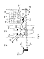
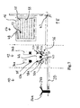
- a simplified placement device comprises a feed station 10, an alignment station 12 and a loading station 14, which are spatially separated from each other - here directly successive - are arranged.
- a fixed fixable holder 16 for a plurality of connector housing 18.
- the connector housing 18 may be engaged in particular in recordings of the pallet-like holder 16, optionally using additional brackets.
- the plug housing 18 shown by way of example in different configurations each have a plurality of cavities 19.
- a first positioning system 20, here in the form of a uniaxial linear system, is assigned to the feed station 10 and serves to move two juxtaposed feed grippers 24a, 24b, which are combined to form a double gripper.
- Fig. 1 In the region of the feed station 10, an electrical line 26 can be seen, which is provided at both ends with respective contact parts 28a, 28b. Each of the contact parts 28a, 28b is held on the electric wire 26 by one of the feed grippers 24a, 24b.
- the feed grippers 24a, 24b could also be designed to hold the contact parts 28a, 28b directly.
- two juxtaposed alignment grippers 32a, 32b are provided which, depending on the application, may also be combined to form a double gripper.
- the alignment grippers 32a, 32b can in principle be designed similar to the feed grippers 24a, 24b.
- the alignment grippers 32a, 32b are respectively rotatable, preferably 180 °, about a rotation of a held contact portion 28a, 28b about an axis of rotation Rz.
- the alignment grippers 32a, 32b are each linearly displaceable along the axis of rotation Rz, as indicated by the straight double arrows.
- Two cameras 34a, 34b are in the region of the alignment station 12 arranged and directed to each one of the alignment grippers 32a, 32b.
- the cameras 34a, 34b could also be connected to a common image processing system.
- An assembly unit 36 assigned to the placement station 14 comprises two placement grippers 38a, 38b and a further camera 40 with associated - own or superordinate - picture processing system.
- a second positioning system 42 which is designed as a biaxial linear system as shown, the placement unit 36 can be moved in front of the individual connector housings 18 fixed to the holder 16. As shown, the first positioning system 20 and the second positioning system 42 overlap one another in the region of the alignment station 12, so that a transfer of held contact parts 28a, 28b between the individual grippers is possible.
- the holder 16 with the fixed plug housings 18 and the second positioning system 42 are shown in a front view in all figures, while the remaining components of the mounting device are shown in a plan view.
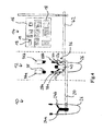
- the contact parts 28a, 28b are then moved to the alignment station 12 by means of the first positioning system 20 and transferred to the alignment grippers 32a, 32b. This handover is in Fig. 2 shown. After the transfer, the feed grippers 24a, 24b are moved back to their original positions and the provision of a further electrical line 26 is started immediately.
- the alignment grippers 32a, 32b perform an alignment process by first determining an actual rotational position of the held contact parts 28a, 28b with respect to the respective rotation axis Rz by means of the cameras 34a, 34b and the associated image processing systems.
- the lenses 35 of the cameras 34a, 34b are in this case respectively on the front end faces 44a, 44b ( Fig. 1 ) of the held contact parts 28a, 28b focused.
- the determined actual rotational position is compared with a predetermined by the nature and the arrangement of the plug housing 18 to be fitted rotational position. Based on the result of the comparison, a rotational position correction is carried out by corresponding rotation of the alignment grippers 32a, 32b.
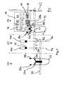
- the two contact parts 28a, 28b are, if necessary, displaced along the respective axis of rotation Rz by means of the alignment grippers 32a, 32b such that the front end faces 44a, 44b of the contact parts 28a, 28b lie on a common reference line 46 running at right angles to the axes of rotation Rz ( Fig. 3 ).
- the placement unit 36 is subsequently moved to the alignment station 12 or even during the alignment process.
- the two ends of the electrical line 26 with the contact parts 28a, 28b are there passed from the alignment grippers 32a, 32b to the loading gripper 38a, 38b, as shown in Fig. 4 is shown.
- the transfer is carried out while avoiding a rotation of the contact parts 28a, 28b.
- any deviations of the positions of the contact parts 28a, 28b in a xy plane perpendicular to the rotation axes Rz are determined relative to respective reference positions.
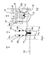
- the placement unit 36 is then positioned in the xy plane in front of the desired connector housing 18 together with the electrical line 26 by means of the second positioning system 42 ( Fig. 5 ).
- the camera 40 of the placement unit 36 determines the exact position including any slight twists the relevant connector housing 18 relative to a predetermined, the camera 40 associated reference position.
- the determined position deviations and twists are temporarily stored in a control device, not shown, and used for assembly operations on further cavities 19 of the relevant plug housing 18.
- the positions of the cavities 19 of a particular connector housing 18 relative to a reference position are taken from a parent database.
- the exact positions of the tips of the contact parts 28a, 28b relative to the reference position of the camera 40 are known.
- the placement unit 36 is now positioned in the xy plane by means of the second positioning system 42 such that the contact part 28a located on the left in the picture is arranged in front of the cavity 19 to be loaded.
- the contact part 28a is inserted into the cavity 19 and optionally locked with this.
- the same process is repeated with the other contact part 28b and the cavity 19 corresponding thereto, so that the in Fig. 6 illustrated state is made.
- the insertion direction E is parallel to the axes of rotation Rz.
- the position of the plug housing 18 is only detected by the camera 40 at the first contact part 28a, 28b. In all other contact parts 28a, 28b for the relevant connector housing 18, the temporarily stored position data are used.
- a further electrical line 26 with contact parts 28a, 28b attached thereto is provided and transported to the alignment station 12 and the process begins from the beginning. If necessary, it is possible to use only a single alignment gripper 32a and only one camera 34a at the alignment station 12.
- Fig. 7 illustrates a calibration method for the mounting device according to the invention, which is carried out using a marking carrier 48 and two marking means 52a, 52b.
- the marking carrier 48 which may be, for example, a paper or film element, is fastened to the holder 16 first.
- respective marking means 52a, 52b are gripped.
- the marking means 52a, 52b are in Fig. 7 generally shown as arrows and may be performed in practice, for example, as pins, needles, laser heads or thermocouples.
- the first loading gripper 38a is moved along a horizontal line.
- the movement is stopped in each case and the loading gripper 38a is moved in the insertion direction E towards the marking carrier 48 until the tip of the marking means 52a contacts it and thereby sets a marking point 55.
- another line of marker points 55 is created with an altered Y position.
- the line by line marking points 55 is repeated until the complete marking carrier 48 is covered by a grid-like dot field as shown.
- the camera 40 of the placement unit 36 is successively moved by means of the second positioning system 42 to the individual marker points 55 and the positions of the marker points 55 on the marker carrier 48 from the displacement position of the second positioning system 42 and the position of the marker point 55th determined in the captured image.
- the positions of the marking points 55 thus determined are stored together with the travel coordinates of the second positioning system 42 in a memory device. Subsequently, will repeats the calibration process with the second loading gripper 38b and the marking means 52b gripped by it.
- the corresponding travel coordinates of the second positioning system 42 can be determined from the positions of the connector housing 18 on the holder 16 using the stored data. Intermediate values can be determined here by suitable mathematical methods, for example by an interpolation method. Any deviations from an orthogonal and linear movement of the placement unit 36, which lead to, for example, a trapezoidal, pincushion-shaped or barrel-shaped distortion of the grid-like dot field are detected by the calibration file and can be compensated accordingly control technology.
- the invention allows a particularly reliable and fast placement of connector housings 18 with electrical leads 26.
Landscapes
- Engineering & Computer Science (AREA)
- Manufacturing & Machinery (AREA)
- Microelectronics & Electronic Packaging (AREA)
- Operations Research (AREA)
- Manufacturing Of Electrical Connectors (AREA)
Priority Applications (6)
| Application Number | Priority Date | Filing Date | Title |
|---|---|---|---|
| EP14172588.7A EP2958201A1 (fr) | 2014-06-16 | 2014-06-16 | Procédé et dispositif d'assemblage d'un boîtier de connexion |
| US15/318,704 US10804667B2 (en) | 2014-06-16 | 2015-06-15 | Device for automatically mounting a connector-housing |
| CN201580032079.9A CN106663909B (zh) | 2014-06-16 | 2015-06-15 | 用于自动安装连接器壳体的设备及方法 |
| EP15730739.8A EP3155700B1 (fr) | 2014-06-16 | 2015-06-15 | Procédé et dispositif d'assemblage d'un boîtier de connexion |
| PCT/EP2015/063350 WO2015193248A1 (fr) | 2014-06-16 | 2015-06-15 | Dispositif et procédé pour l'équipement automatique d'un boîtier de connexion |
| US17/068,289 US11641086B2 (en) | 2014-06-16 | 2020-10-12 | Method for automatically mounting a connector-housing |
Applications Claiming Priority (1)
| Application Number | Priority Date | Filing Date | Title |
|---|---|---|---|
| EP14172588.7A EP2958201A1 (fr) | 2014-06-16 | 2014-06-16 | Procédé et dispositif d'assemblage d'un boîtier de connexion |
Publications (1)
| Publication Number | Publication Date |
|---|---|
| EP2958201A1 true EP2958201A1 (fr) | 2015-12-23 |
Family
ID=50976481
Family Applications (2)
| Application Number | Title | Priority Date | Filing Date |
|---|---|---|---|
| EP14172588.7A Withdrawn EP2958201A1 (fr) | 2014-06-16 | 2014-06-16 | Procédé et dispositif d'assemblage d'un boîtier de connexion |
| EP15730739.8A Revoked EP3155700B1 (fr) | 2014-06-16 | 2015-06-15 | Procédé et dispositif d'assemblage d'un boîtier de connexion |
Family Applications After (1)
| Application Number | Title | Priority Date | Filing Date |
|---|---|---|---|
| EP15730739.8A Revoked EP3155700B1 (fr) | 2014-06-16 | 2015-06-15 | Procédé et dispositif d'assemblage d'un boîtier de connexion |
Country Status (4)
| Country | Link |
|---|---|
| US (2) | US10804667B2 (fr) |
| EP (2) | EP2958201A1 (fr) |
| CN (1) | CN106663909B (fr) |
| WO (1) | WO2015193248A1 (fr) |
Cited By (2)
| Publication number | Priority date | Publication date | Assignee | Title |
|---|---|---|---|---|
| EP3238886A1 (fr) * | 2016-04-25 | 2017-11-01 | The Boeing Company | Procédés de fonctionnement d'une machine automatisée pour insérer des fils dans des emplacements de cavité d' oeillet d'un connecteur électrique |
| EP3540875A1 (fr) * | 2018-03-16 | 2019-09-18 | Cemra | Dispositif et procédé d'insertion comprenant des moyens d'alignement de l'axe longitudinal de la cosse |
Families Citing this family (2)
| Publication number | Priority date | Publication date | Assignee | Title |
|---|---|---|---|---|
| DE102017128295A1 (de) | 2017-11-29 | 2019-05-29 | Rittal Gmbh & Co. Kg | Verfahren für die elektrische Verkabelung elektronischer Komponenten im Schaltanlagenbau und eine entsprechende Anordnung |
| DE102019207253B4 (de) * | 2019-05-17 | 2021-06-10 | Leoni Bordnetz-Systeme Gmbh | Vorrichtung sowie Verfahren zum automatischen Konfektionieren eines Leitungspaares |
Citations (3)
| Publication number | Priority date | Publication date | Assignee | Title |
|---|---|---|---|---|
| US6043877A (en) * | 1996-11-26 | 2000-03-28 | U.S. Philips Corporation | Calibration carrier for a component placement machine having an adhesive reflective surface |
| US20090199396A1 (en) * | 2008-02-09 | 2009-08-13 | Cirris Systems Corporation | Apparatus for electrical pin installation and retention confirmation |
| EP2461433A1 (fr) * | 2010-12-01 | 2012-06-06 | Delphi Technologies, Inc. | Procédé et dispositif d'assemblage d'un boîtier de connexion |
Family Cites Families (27)
| Publication number | Priority date | Publication date | Assignee | Title |
|---|---|---|---|---|
| US3867760A (en) * | 1971-05-10 | 1975-02-25 | Molex Products Co | Printed circuit board lead wire receptacle |
| EP0348615B1 (fr) | 1988-07-01 | 1994-06-15 | Komax Ag | Procédé de montage automatique de conducteurs électriques avec des pièces de contact dans des boîtiers de connecteurs |
| EP0355836A3 (fr) * | 1988-08-24 | 1991-05-02 | TDK Corporation | Dispositif et méthode de montage automatique de composants électroniques sur une plaque à circuits imprimés |
| FR2643721B1 (fr) * | 1989-02-28 | 1991-06-28 | Aerospatiale | Systeme pour verifier le branchement d'extremites de conducteurs dans un connecteur, et installation automatique de branchement equipee dudit systeme |
| JP2836725B2 (ja) * | 1993-11-29 | 1998-12-14 | 矢崎総業株式会社 | 端子挿入方法及び端子挿入装置 |
| CH689288A5 (de) | 1994-10-21 | 1999-01-29 | Komax Holding Ag | Verfahren und Vorrichtung zum Bestuecken von Steckergehaeusen. |
| BE1009814A5 (nl) * | 1995-11-06 | 1997-08-05 | Framatome Connectors Belgium | Werkwijze en inrichting voor het aanbrengen van elektronische onderdelen in een plaat met gedrukte schakelingen. |
| JP3301007B2 (ja) * | 1995-11-10 | 2002-07-15 | 矢崎総業株式会社 | 端子挿入方法 |
| US6868603B2 (en) | 1996-08-27 | 2005-03-22 | Matsushita Electric Industrial Co., Ltd. | Method of mounting component on circuit board |
| EP1032094B1 (fr) | 1999-02-25 | 2003-05-28 | Sumitomo Wiring Systems, Ltd. | Améliorations relatives au montage des bornes avec fils électriques dans des boitiers de connecteurs |
| EP1073163B1 (fr) | 1999-07-26 | 2003-05-14 | komax Holding AG | Dispositif de transport d'extrémités de câble pour une unité de confection de câbles |
| US6862803B2 (en) | 2000-08-29 | 2005-03-08 | Matsushita Electric Industrial Co., Ltd. | Method for mounting electronic component |
| EP1251605B1 (fr) | 2001-04-10 | 2004-07-21 | Komax Holding Ag | Appareil et méthode pour l'insertion de bout de câble dans des boítiers de connecteurs |
| EP1429430B1 (fr) | 2001-10-05 | 2008-03-19 | Komax Holding Ag | Procédé et dispositif pour la mise en place d'extrémités de câble préparés d'un câble dans des boîtiers de connecteur |
| DE50214847D1 (de) * | 2001-10-31 | 2011-02-17 | Komax Holding Ag | Handhabungsvorrichtung für Drahtleitung, Einführungsmaschine und Einführungsverfahren mit einer solchen Handhabungsvorrichtung |
| EP1317031B1 (fr) | 2001-10-31 | 2011-01-05 | Komax Holding AG | Manipulateur de fil conducteur, machine et procédé d'insertion incorporant un tel manipulateur |
| AU2002350237A1 (en) | 2001-11-24 | 2003-06-10 | Delphi Technologies, Inc. | Improvements in wire harnesses |
| JP4033705B2 (ja) | 2002-05-08 | 2008-01-16 | 富士機械製造株式会社 | プリント配線板位置誤差取得方法,プログラムおよび電子回路部品装着システム |
| JP4079949B2 (ja) * | 2005-01-20 | 2008-04-23 | 第一精工株式会社 | コネクタ製造装置およびコネクタ製造方法 |
| JP4337103B2 (ja) * | 2005-08-26 | 2009-09-30 | アサヒ精機株式会社 | 電線装着装置、及び挿入構造 |
| EP1786072B1 (fr) | 2005-11-10 | 2008-07-16 | komax Holding AG | Dispositif de traitement de câble et méthode d'utilisation |
| JP4917418B2 (ja) * | 2006-12-14 | 2012-04-18 | タイコエレクトロニクスジャパン合同会社 | 端子挿入装置 |
| CN101847817B (zh) * | 2010-03-31 | 2012-01-04 | 中航光电科技股份有限公司 | 一种电连接器自动装配方法及电连接器自动装配机 |
| KR101305380B1 (ko) | 2012-05-30 | 2013-09-17 | 삼성전기주식회사 | 기판 검사 장치 및 그 위치 보정 방법 |
| CN202817460U (zh) | 2012-08-22 | 2013-03-20 | 东莞市星擎电子科技有限公司 | 串口插座自动生产机器 |
| US9317023B2 (en) * | 2012-09-20 | 2016-04-19 | Tyco Electronics Corporation | Wire sorting machine and method of sorting wires |
| DE102014005242B3 (de) | 2014-04-08 | 2015-07-09 | SLE quality engineering GmbH & Co. KG | Verfahren und Vorrichtung zum Bestimmen einer Winkellage von Einzelleitungen an einer vorbestimmten Querschnittsstelle in einer mehradrigen Mantelleitung |
-
2014
- 2014-06-16 EP EP14172588.7A patent/EP2958201A1/fr not_active Withdrawn
-
2015
- 2015-06-15 EP EP15730739.8A patent/EP3155700B1/fr not_active Revoked
- 2015-06-15 CN CN201580032079.9A patent/CN106663909B/zh active Active
- 2015-06-15 WO PCT/EP2015/063350 patent/WO2015193248A1/fr active Application Filing
- 2015-06-15 US US15/318,704 patent/US10804667B2/en active Active
-
2020
- 2020-10-12 US US17/068,289 patent/US11641086B2/en active Active
Patent Citations (3)
| Publication number | Priority date | Publication date | Assignee | Title |
|---|---|---|---|---|
| US6043877A (en) * | 1996-11-26 | 2000-03-28 | U.S. Philips Corporation | Calibration carrier for a component placement machine having an adhesive reflective surface |
| US20090199396A1 (en) * | 2008-02-09 | 2009-08-13 | Cirris Systems Corporation | Apparatus for electrical pin installation and retention confirmation |
| EP2461433A1 (fr) * | 2010-12-01 | 2012-06-06 | Delphi Technologies, Inc. | Procédé et dispositif d'assemblage d'un boîtier de connexion |
Cited By (5)
| Publication number | Priority date | Publication date | Assignee | Title |
|---|---|---|---|---|
| EP3238886A1 (fr) * | 2016-04-25 | 2017-11-01 | The Boeing Company | Procédés de fonctionnement d'une machine automatisée pour insérer des fils dans des emplacements de cavité d' oeillet d'un connecteur électrique |
| US10649442B2 (en) | 2016-04-25 | 2020-05-12 | The Boeing Company | Methods of operating an automated machine for inserting wires into grommet cavity locations of an electrical connector |
| US11662713B2 (en) | 2016-04-25 | 2023-05-30 | The Boeing Company | Automated machine for inserting wires into grommet cavity locations of an electrical connector and methods of operating |
| EP3540875A1 (fr) * | 2018-03-16 | 2019-09-18 | Cemra | Dispositif et procédé d'insertion comprenant des moyens d'alignement de l'axe longitudinal de la cosse |
| FR3079079A1 (fr) * | 2018-03-16 | 2019-09-20 | Cemra | Dispositif et procede d’insertion comprenant des moyens d’alignement de l’axe longitudinal de la cosse |
Also Published As
| Publication number | Publication date |
|---|---|
| CN106663909A (zh) | 2017-05-10 |
| EP3155700A1 (fr) | 2017-04-19 |
| US20210028589A1 (en) | 2021-01-28 |
| US11641086B2 (en) | 2023-05-02 |
| US10804667B2 (en) | 2020-10-13 |
| CN106663909B (zh) | 2019-02-15 |
| EP3155700B1 (fr) | 2018-07-11 |
| WO2015193248A1 (fr) | 2015-12-23 |
| US20170133809A1 (en) | 2017-05-11 |
Similar Documents
| Publication | Publication Date | Title |
|---|---|---|
| EP3947212B1 (fr) | Dispositif et procédé de montage d'un connecteur électrique enfichable | |
| EP3155700B1 (fr) | Procédé et dispositif d'assemblage d'un boîtier de connexion | |
| DE102017118713B3 (de) | Vorrichtung und Verfahren zum Anschweißen von Hartstoffkörpern an Zähnen eines Sägeblatts | |
| DE102017118707B3 (de) | Vorrichtung zum Anschweißen von Hartstoffkörpern an Zähnen eines Sägeblatts | |
| EP3717182B1 (fr) | Procédé pour le câblage électrique par une séquence de câbles de composants électroniques dans la construction d'installations de commutation et dispositif robotique correspondant | |
| EP3900131A1 (fr) | Procédé de câblage assisté par robot de composants électriques d'une installation de distribution électrique montée sur une plaque de montage | |
| EP3900130B1 (fr) | Méthode de câblage de composants électriques d'un circuit de commutation disposé sur une platine de montage | |
| DE102015017014B4 (de) | Anker mit Wicklungen und Verfahren zum Verbinden von Wicklungsenden des Ankers mit einer Anschlussklemme | |
| EP2779327B1 (fr) | Pince rotative pour câble et méthode de guidage d'un conducteur électrique | |
| EP2748895B1 (fr) | Dispositif de sertissage | |
| DE3703010C2 (fr) | ||
| WO2022090406A1 (fr) | Dispositif et procédé d'assemblage de connecteur mâle | |
| EP3651288A1 (fr) | Station de distribution | |
| DE19756978C1 (de) | Verfahren und Vorrichtung zur Fertigung von Kabelmodulen | |
| EP3155699B1 (fr) | Procédé de calibrage d'un dispositif de revêtement | |
| EP2654141B1 (fr) | Procédé et dispositif de fabrication d'un connecteur | |
| EP0444032B1 (fr) | Procede et dispositif de fabrication d'harnais de cables | |
| WO2018104242A1 (fr) | Dispositif, procédé et système de sertissage inverse | |
| DE102017215028A1 (de) | Verfahren zum Herstellen eines mindestens zwei Komponenten, wie Bauteile und/oder Baugruppen, umfassenden Produkts, Bearbeitungsanlage und Produkt | |
| DE102019130288A1 (de) | Vorrichtung, Verfahren und System zur Montage eines elektrischen Steckverbinders | |
| DE112020002910T5 (de) | Verfahren und Vorrichtung zur Herstellung eines Kabelstrangs | |
| DE102021107967A1 (de) | Vorrichtung zum Verbinden von, von einem Wickelkopf eines Stators abragenden, Statoranschlussdrähten mit Ringanschlussdrähten eines Verschaltungsrings | |
| EP4211758A1 (fr) | Centre de traitement de câbles | |
| EP4029092A1 (fr) | Procédé de traitement des extrémités d'au moins un conducteur électrique |
Legal Events
| Date | Code | Title | Description |
|---|---|---|---|
| PUAI | Public reference made under article 153(3) epc to a published international application that has entered the european phase |
Free format text: ORIGINAL CODE: 0009012 |
|
| AK | Designated contracting states |
Kind code of ref document: A1 Designated state(s): AL AT BE BG CH CY CZ DE DK EE ES FI FR GB GR HR HU IE IS IT LI LT LU LV MC MK MT NL NO PL PT RO RS SE SI SK SM TR |
|
| AX | Request for extension of the european patent |
Extension state: BA ME |
|
| STAA | Information on the status of an ep patent application or granted ep patent |
Free format text: STATUS: THE APPLICATION IS DEEMED TO BE WITHDRAWN |
|
| 18D | Application deemed to be withdrawn |
Effective date: 20160624 |