EP2461433A1 - Procédé et dispositif d'assemblage d'un boîtier de connexion - Google Patents
Procédé et dispositif d'assemblage d'un boîtier de connexion Download PDFInfo
- Publication number
- EP2461433A1 EP2461433A1 EP10015198A EP10015198A EP2461433A1 EP 2461433 A1 EP2461433 A1 EP 2461433A1 EP 10015198 A EP10015198 A EP 10015198A EP 10015198 A EP10015198 A EP 10015198A EP 2461433 A1 EP2461433 A1 EP 2461433A1
- Authority
- EP
- European Patent Office
- Prior art keywords
- spatially resolved
- robot
- holder
- resolved image
- contact part
- Prior art date
- Legal status (The legal status is an assumption and is not a legal conclusion. Google has not performed a legal analysis and makes no representation as to the accuracy of the status listed.)
- Granted
Links
Images


Classifications
-
- H—ELECTRICITY
- H01—ELECTRIC ELEMENTS
- H01R—ELECTRICALLY-CONDUCTIVE CONNECTIONS; STRUCTURAL ASSOCIATIONS OF A PLURALITY OF MUTUALLY-INSULATED ELECTRICAL CONNECTING ELEMENTS; COUPLING DEVICES; CURRENT COLLECTORS
- H01R43/00—Apparatus or processes specially adapted for manufacturing, assembling, maintaining, or repairing of line connectors or current collectors or for joining electric conductors
- H01R43/20—Apparatus or processes specially adapted for manufacturing, assembling, maintaining, or repairing of line connectors or current collectors or for joining electric conductors for assembling or disassembling contact members with insulating base, case or sleeve
-
- B—PERFORMING OPERATIONS; TRANSPORTING
- B25—HAND TOOLS; PORTABLE POWER-DRIVEN TOOLS; MANIPULATORS
- B25J—MANIPULATORS; CHAMBERS PROVIDED WITH MANIPULATION DEVICES
- B25J9/00—Programme-controlled manipulators
- B25J9/16—Programme controls
- B25J9/1615—Programme controls characterised by special kind of manipulator, e.g. planar, scara, gantry, cantilever, space, closed chain, passive/active joints and tendon driven manipulators
- B25J9/162—Mobile manipulator, movable base with manipulator arm mounted on it
-
- B—PERFORMING OPERATIONS; TRANSPORTING
- B25—HAND TOOLS; PORTABLE POWER-DRIVEN TOOLS; MANIPULATORS
- B25J—MANIPULATORS; CHAMBERS PROVIDED WITH MANIPULATION DEVICES
- B25J9/00—Programme-controlled manipulators
- B25J9/16—Programme controls
- B25J9/1679—Programme controls characterised by the tasks executed
- B25J9/1687—Assembly, peg and hole, palletising, straight line, weaving pattern movement
-
- G—PHYSICS
- G01—MEASURING; TESTING
- G01B—MEASURING LENGTH, THICKNESS OR SIMILAR LINEAR DIMENSIONS; MEASURING ANGLES; MEASURING AREAS; MEASURING IRREGULARITIES OF SURFACES OR CONTOURS
- G01B11/00—Measuring arrangements characterised by the use of optical techniques
- G01B11/002—Measuring arrangements characterised by the use of optical techniques for measuring two or more coordinates
-
- G—PHYSICS
- G05—CONTROLLING; REGULATING
- G05B—CONTROL OR REGULATING SYSTEMS IN GENERAL; FUNCTIONAL ELEMENTS OF SUCH SYSTEMS; MONITORING OR TESTING ARRANGEMENTS FOR SUCH SYSTEMS OR ELEMENTS
- G05B2219/00—Program-control systems
- G05B2219/30—Nc systems
- G05B2219/40—Robotics, robotics mapping to robotics vision
- G05B2219/40033—Assembly, microassembly
-
- G—PHYSICS
- G05—CONTROLLING; REGULATING
- G05B—CONTROL OR REGULATING SYSTEMS IN GENERAL; FUNCTIONAL ELEMENTS OF SUCH SYSTEMS; MONITORING OR TESTING ARRANGEMENTS FOR SUCH SYSTEMS OR ELEMENTS
- G05B2219/00—Program-control systems
- G05B2219/30—Nc systems
- G05B2219/40—Robotics, robotics mapping to robotics vision
- G05B2219/40298—Manipulator on vehicle, wheels, mobile
-
- Y—GENERAL TAGGING OF NEW TECHNOLOGICAL DEVELOPMENTS; GENERAL TAGGING OF CROSS-SECTIONAL TECHNOLOGIES SPANNING OVER SEVERAL SECTIONS OF THE IPC; TECHNICAL SUBJECTS COVERED BY FORMER USPC CROSS-REFERENCE ART COLLECTIONS [XRACs] AND DIGESTS
- Y10—TECHNICAL SUBJECTS COVERED BY FORMER USPC
- Y10T—TECHNICAL SUBJECTS COVERED BY FORMER US CLASSIFICATION
- Y10T29/00—Metal working
- Y10T29/49—Method of mechanical manufacture
- Y10T29/49002—Electrical device making
- Y10T29/49117—Conductor or circuit manufacturing
- Y10T29/49124—On flat or curved insulated base, e.g., printed circuit, etc.
- Y10T29/49147—Assembling terminal to base
-
- Y—GENERAL TAGGING OF NEW TECHNOLOGICAL DEVELOPMENTS; GENERAL TAGGING OF CROSS-SECTIONAL TECHNOLOGIES SPANNING OVER SEVERAL SECTIONS OF THE IPC; TECHNICAL SUBJECTS COVERED BY FORMER USPC CROSS-REFERENCE ART COLLECTIONS [XRACs] AND DIGESTS
- Y10—TECHNICAL SUBJECTS COVERED BY FORMER USPC
- Y10T—TECHNICAL SUBJECTS COVERED BY FORMER US CLASSIFICATION
- Y10T29/00—Metal working
- Y10T29/49—Method of mechanical manufacture
- Y10T29/49002—Electrical device making
- Y10T29/49117—Conductor or circuit manufacturing
- Y10T29/49204—Contact or terminal manufacturing
- Y10T29/49208—Contact or terminal manufacturing by assembling plural parts
-
- Y—GENERAL TAGGING OF NEW TECHNOLOGICAL DEVELOPMENTS; GENERAL TAGGING OF CROSS-SECTIONAL TECHNOLOGIES SPANNING OVER SEVERAL SECTIONS OF THE IPC; TECHNICAL SUBJECTS COVERED BY FORMER USPC CROSS-REFERENCE ART COLLECTIONS [XRACs] AND DIGESTS
- Y10—TECHNICAL SUBJECTS COVERED BY FORMER USPC
- Y10T—TECHNICAL SUBJECTS COVERED BY FORMER US CLASSIFICATION
- Y10T29/00—Metal working
- Y10T29/49—Method of mechanical manufacture
- Y10T29/49826—Assembling or joining
-
- Y—GENERAL TAGGING OF NEW TECHNOLOGICAL DEVELOPMENTS; GENERAL TAGGING OF CROSS-SECTIONAL TECHNOLOGIES SPANNING OVER SEVERAL SECTIONS OF THE IPC; TECHNICAL SUBJECTS COVERED BY FORMER USPC CROSS-REFERENCE ART COLLECTIONS [XRACs] AND DIGESTS
- Y10—TECHNICAL SUBJECTS COVERED BY FORMER USPC
- Y10T—TECHNICAL SUBJECTS COVERED BY FORMER US CLASSIFICATION
- Y10T29/00—Metal working
- Y10T29/51—Plural diverse manufacturing apparatus including means for metal shaping or assembling
- Y10T29/5136—Separate tool stations for selective or successive operation on work
- Y10T29/5137—Separate tool stations for selective or successive operation on work including assembling or disassembling station
Definitions
- the invention relates to a method and a device for populating a plug housing with a contact part attached to an electrical line by a mobile robot and a method for calibrating a control unit of a mobile robot.
- a mounting method as described above is known, in which the connector housing is fixed to a holder, the electrical line is gripped with a contact part of a robot and a spatially resolved image of the connector housing is received by an optical detection device.
- an optical detection device By evaluating the image of the connector housing is detected in the known method, when the connector housing is disposed in the holder against its desired standard position unintentionally inclined or offset, and it is performed a correction of a relative position of the robot with respect to the connector housing.
- the object of the invention is therefore to provide a method and a device for populating a plug housing with a mounted on an electrical line contact part by a mobile robot, which also when using tolerant robots, connector housings, Holders and / or contact parts allow a precise, error-free and fast placement of a connector housing with a mounted on an electrical line contact part.
- At least one spatially resolved image is recorded both by the connector housing fixed to the holder and by the contact part received by the gripping device.
- one and the same recorded spatially resolved image may comprise both the plug housing and the contact part, or the plug housing and the contact part may be in different recorded spatially resolved Be included pictures.
- the recording of the spatially resolved images represents an optical measurement of the respectively imaged region, which comprises the plug housing or the contact part.
- a spatially resolved image a certain part such. contains the plug housing or the contact part, is in the context of the invention not only to understand that the respective part is included with its entire circumference in the image, but it can also be shown only a section of the part in the image.
- only a portion of a plug housing may be included in the at least one spatially resolved image, which includes, for example, a plug cavity formed for receiving the contact part of the plug housing, which is referred to for determining the position of the plug housing. It must then be visible only a section of the connector housing in the image, which is sufficiently large that the respective connector cavity or another predefined reference point of the connector housing can be identified in the image.
- a first spatially resolved image is recorded, which contains the connector housing, and a second spatially resolved image, which differs from the first spatially resolved image, which contains the contact part.
- the position of the plug housing in the first image and the position of the contact part in the second image can then be used.
- the first and / or the second image may also contain both the plug housing and the contact part.
- the first spatially resolved image is received from a front side of the plug housing, from which the contact part is inserted into the plug housing, and the second spatially resolved image containing the contact part is received from a rear side of the plug housing.
- the first and the second spatially resolved image can be captured by one and the same optical detection device or by different optical detection devices, which in particular can be mounted independently of each other. When both images are taken with the same optical detection device, a movable optical detection device may be used which alternates between capturing the first and second images between different locations.
- a preferred embodiment provides that the first spatially resolved image contains the holder, wherein a position of the plug housing relative to the holder in the first spatially resolved image is determined and / or that the second spatially resolved image contains the holder, wherein a position of the contact part relative to the holder in the second spatially resolved image is determined.
- the contact part For receiving a spatially resolved image containing the contact part and the holder which can be evaluated well, the contact part can be moved by the robot into the vicinity of the holder before the spatially resolved image is recorded. This can be done in such a way that the contact part is located approximately at the same distance from the optical detection device as the holder.
- a spatially resolved image taken by the optical detection device contains information about the position of the objects respectively contained in the image, e.g. of the male housing and the contact part, with respect to a position and orientation of the optical resolution device receiving the respective spatially resolved image in space, i. It can be seen from the image where the imaged object is located with respect to an image plane of the optical detection device that is perpendicular to an optical axis of the optical detection device.
- the positions of the male housing and the contact part in the respective image determined from the at least one spatially resolved image are set to corresponding positions in a reference frame of the robot so that the robot can correctly approach the actual position of the connector housing.
- at least one recorded spatially resolved image contains the gripping device of the robot and a position of the gripping device is determined in the at least one spatially resolved image.
- the position of the gripping device determined in this way with respect to the image-capturing optical detection device is compared with the internal coordinates of the gripping device determined in a control unit of the robot and a coordinate transformation is determined therefrom with the positions determined with respect to the optical detection device, eg of the plug housing and the contact part in the reference system of the control unit of the robot can be converted.
- another part of the robot than the gripping device as described above can also be imaged and image-processed by the optical detection device in order to determine the position of the robot.
- the position of the gripping device is determined in at least one spatially resolved image relative to the holder contained in the same image.
- the holder may each comprise one or more reference features on a front and / or back side. According to an advantageous embodiment, it is then provided that a position of the plug housing relative to at least one reference feature of the holder contained in the first spatially resolved image is determined, and / or that a position of the contact part relative to at least one reference feature of the holder contained in the second spatially resolved image is determined.
- the use of such reference features facilitates the determination of the position of the contact part or of the plug housing relative to the holder, in particular if the respective spatially resolved image contains only a section of the holder.
- several reference features of the Halters be designed essentially the same.
- a plurality of reference features of the holder are distinguishable from one another and represent, for example, codings, wherein in an exemplary embodiment a reference feature in a spatially resolved image containing the reference feature is uniquely identified on the basis of its coding.
- Two-dimensional images of the respective imaged spatial area can be recorded with an optical detection device.
- a position and orientation of the respective part in space i. in three dimensions, calculated.
- the two-dimensional positions of two, three or more reference points of the respective part in the respective spatially resolved image can be determined.
- it can be calculated for each part of its position and / or orientation in space.
- the position of the plug housing is determined relative to a plurality of reference features of the holder contained in a first spatially resolved image which contains the plug housing and the holder as described above, and / or that the position of the contact part relative to a plurality in a second spatially resolved image, which is as described above contains the contact part and the holder, contained reference features of the holder is determined.
- These multiple relative positions determined in the first and second images, respectively, may be used to calculate the position and / or orientation of the plug housing or contact member relative to the holder in three dimensions.
- a curvature of the electrical line in the spatially resolved image containing the contact part is determined and from this a deflection of the contact part relative to the gripping device is calculated.
- a holder which comprises a plurality of holding devices for fixing a plurality of plug housings. It can then be determined first the positions of the connector housing and then all connector housings are equipped with contact parts. To determine the positions of the connector housing, a plurality of spatially resolved images may be recorded, which contain different connector housings, wherein the holder for receiving the multiple images by means of a drive are gradually passed by an optical detection device, each having a spatially resolved image of the located before the detection device portion of Halters receives.
- the various recorded sections can be distinguished on the basis of distinguishable reference features arranged in the respective sections of the holder, and the recorded images can thus be assigned to the respective holder sections.
- plug housings can be equipped with the method according to the invention, which, for example, different numbers and / or different arrangements of plug cavities can contain.
- the type of a plug housing type fixed to a specific holder is preferably determined independently of the optical image recording and image processing performed to determine the position of the plug housing and communicated to a controller of the robot, whereupon an automatic placement of the plug cavities of the respective plug housing with contact parts is performed depending on the determined type.
- an optical detection device with a de-centric objective is used to record the at least one spatially resolved image.
- Optical distortions of a lens used can be determined and corrected in the subsequent image processing by taking an image of a pre-specified reference pattern, in particular a regular reference pattern such as e.g. a checkerboard pattern is picked up with the detection device and the distortions contained in the image are calculated.
- a spatially resolved image is first taken from both sides of the holder, each image containing one or more arranged on the respective side of the holder reference features and a mark of the holder, which is visible from both sides of the holder.
- the positions of the reference features relative to the markings are then determined.
- further spatially resolved images containing the reference features can be recorded from both sides of the holder, for which purpose in particular the holder can be guided stepwise past an optical detection device.
- a correction table with correction values can be created, which specifies an offset between reference features provided on one side and on the other side of the holder.
- the device according to the invention can be designed in particular for carrying out the method according to the invention.
- the advantageous embodiments and advantages described above in relation to the method apply correspondingly to the device.
- the holder has a plurality of reference features.
- the holder may have both on a front side and on a rear side one or more reference features which are visible only from the respective front or back side of the holder and / or one or more markings which are visible from both sides of the holder ,
- At least one of the reference features is designed as a data matrix code.
- a data matrix code can in particular be applied to a plastic film of the holder.
- a plurality of data matrix codes differ from one another, so that each reference feature can be uniquely identified on the basis of the data matrix codes.
- the internal coordinates of the robot stored in the control unit in the reference position indicate how the robot is positioned and oriented in space with respect to the optical detection apparatus. This information can be used by the control unit to convert positions detected by the optical detection device into the reference frame of the robot, thus allowing the robot to be reliably controlled to reliably reach a predetermined position of an object.
- the coordinates may include both coordinates of a position and an orientation of the part of the robot in space.
- the above-mentioned steps a) to d) are performed at least once with a reference object attached to a flange of the robot and at least once with a gripper device of the robot attached to the flange of the robot.
- the position and orientation of a gripper relative to a position and orientation of the robot flange can be determined in three-dimensional coordinates, although a spatially resolved image contains only one image in two coordinates.
- This information can be subsequently used by the control unit to exactly approach a predetermined position with the gripping device.
- the same reference object can be used in particular for the flange of the robot and for the gripping device.
- an inaccurate design of the reference object has no influence on the accuracy of the measurement, since in both steps substantially the same measurement errors are made and these thus compensate for the determination of the relative position of robot flange and gripping device.
- the reference object can be attached to a holding device of a robot flange, which serves for fastening a gripping device of the robot.
- a calibration board with a checkerboard pattern can be used as a reference object.
- the calibration board may comprise four reference marks arranged in a rectangle and / or a vertically projecting pin, which may be arranged in particular in the center of the board and which may contain a marking point in its center.
- the reference position of the reference object can be defined in such a way that it is reached when, in the recorded image, the marker point is at the center of a rectangle consisting of the four reference marks and the panel thus stands perpendicular to the optical capture device. From the size of the reference object in the captured image, the distance of the robot from the optical detection device can then be determined.
- the inventive calibration method for the control unit of a robot can be used in particular in combination with a mounting method as described above.
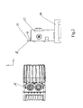
- Fig. 1 shows a perspective view of a mounting device according to an embodiment of the invention.
- the device includes a holder 10 with a plurality of holding devices 12, in each of which a connector housing 14 is fixed by latching.
- the holding devices 12 of the holder 10 are arranged successively in a longitudinal direction x of the holder 10 and releasably connected to a base portion of the holder 10.
- a first optical detection device 16 is directed to a back side 26 of the holder 10, from which a contact part 20 (see Fig. 4 ) can be inserted into a plug cavity 22 of a plug housing 14 is and is adapted to receive a spatially resolved image including the holder 10 and a connector housing 14.
- the holder 10 comprises a plurality of reference features 24 formed as data matrix codes, which are arranged on a carrier 28 in the longitudinal direction x of the holder 10 successively at regular intervals and form a ruler with the carrier 28.
- reference marks 24 are arranged both on the rear side 26 and on a front side 18 of the holder 10, which are only visible from the front or rear side 18, 26, respectively.
- reference features could also be visible from both sides 18, 26 and, for example, be applied to a transparent carrier material.
- the optical detection device 16 and the holder 10 are arranged so that the optical axis of the optical detection device 16 and the insertion direction z, in which a contact part 20 is inserted into a connector housing 14, are substantially parallel.
- the holder 10 is moved to receive the images containing the various connector housing 14 in its longitudinal direction x by a suitable drive and past the optical detection device 16.
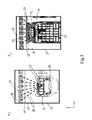
- FIG. 3a and 3b For example, exemplary spatially resolved images 27 taken with the optical detection device 16 are shown in FIG Fig. 3a and b indicated by arrows 30, from the spatially resolved images of the optical detection device 16 in each case the position of a particular plug cavity 22 of the illustrated connector housing 14 relative to a plurality of reference features 24 of the holder 10 is determined.
- the reference features 24 can by evaluating the corresponding data matrix Codes are identified by image processing of the spatially resolved image and associated with the respectively mated connector housing 14.
- Image processing also detects a type of plug housing 14 shown in a spatially resolved image 27, with automatic placement of all plug cavities 22 of the plug housing 14 being performed during the later assembly, depending on the identified type and on stored arrangements of the plug cavities 22 for the respective type ,
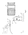
- Fig. 4 shows the device of Fig. 1 and 2 while taking another in Fig. 6
- the spatially resolved image 34 shown by way of example is directed by a second optical detection device 42, which is directed onto the front side 18 of the holder 10.
- a second optical detection device 42 which is directed onto the front side 18 of the holder 10.
- Fig. 4 only one holding device 12 of the holder 10 is shown.
- Fig. 4 is an electric wire 36 having a contact part 20 attached to the electric wire 36 is gripped by a gripping device 38 of a robot 40 and moved in the vicinity of the holder 10 such that an end face 41 of the contact part 20 and the holder 10 as in Fig. 5 are shown approximately equidistant from the optical detection device.
- This in Fig. 6 shown with the optical detection device 42 recorded spatially resolved image 34 includes the contact portion 20 and a plurality of reference features 24 of the holder 10. As in Fig. 6 indicated by the arrows 44, the relative position of the contact part 20 relative to the plurality of reference features 24 in the spatially resolved image 34 is determined. In addition, a curvature of the electrical line 36 in the spatially resolved Figure 34 determines and determines a deflection of the contact part 20 relative to the gripping device 38.
- the device is configured to provide a plug-in housing 14 as shown in FIG Fig. 3a and b taken and then for each electrical line 36 a as in Fig. 6 to record the image shown and using the determined positions of the connector housing 14 and the respective contact part 20, the plug cavities 22 of the connector housing 14 in order to equip with contact parts 20 in turn.
- Fig. 7a and b each show an example with an as in Fig. 1 . 2 or 4 . 5 shown optical resolution device 16, 42 recorded spatially resolved image 48, which is used for calibration of the holder 10 and the reference features 24.
- FIG. 7a and 7b shown images are each received from a front side 18 of the holder 10 ago, wherein Fig. 7a the left lateral end region and Fig. 7b show the right side end portion of the holder 10 with a received connector housing 14.
- Each spatially resolved image 48 includes a marker 50 of the holder 10 which is visible from both sides 18, 26 of the holder 10 and serves as a reference for the calibration of the reference features 24.
- each spatially resolved image 48 the positions of the reference features 24 contained in the respective image are determined to the marker 50.
- the markers 50 and on the back 26 of the holder 10 arranged reference features 24 included.
- the positions on the front side become 18 of the holder 10 is arranged Reference features 24 relative to the arranged on the back 26 reference features 24 determined.
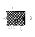
- Fig. 8 shows a reference object 52, which is suitable for carrying out the method according to the invention for calibrating a control unit of a mobile robot.
- the reference object 52 comprises a panel 54 with an applied checkerboard pattern 56 and four reference marks 58 arranged in a rectangle and a vertically projecting pin 60 in the center of the panel with a marker point 62.
- the reference object 52 is attachable to a robot flange or robot gripper.
- a spatially resolved image of the reference object 52 is continuously generated by means of an optical detection device.
- the robot is actuated in order to place the reference object 52 in a reference position in front of the optical detection device, in which a prespecified image of the reference object 52 results in the optical detection device.
- the reference position is achieved in the present exemplary embodiment if, in the recorded image, the center point 62 of the reference object 52 is located in the center of a rectangle formed from the four reference marks 58.
- the panel 54 is then perpendicular to the optical axis of the optical detection device. In this reference position will be then the internal detected by the control unit coordinates of the robot detected and subsequently used for calibration.
Priority Applications (2)
| Application Number | Priority Date | Filing Date | Title |
|---|---|---|---|
| EP20100015198 EP2461433B1 (fr) | 2010-12-01 | 2010-12-01 | Procédé et dispositif d'assemblage d'un boîtier de connexion |
| US13/305,096 US8832934B2 (en) | 2010-12-01 | 2011-11-28 | Method for fitting of a plug housing |
Applications Claiming Priority (1)
| Application Number | Priority Date | Filing Date | Title |
|---|---|---|---|
| EP20100015198 EP2461433B1 (fr) | 2010-12-01 | 2010-12-01 | Procédé et dispositif d'assemblage d'un boîtier de connexion |
Publications (2)
| Publication Number | Publication Date |
|---|---|
| EP2461433A1 true EP2461433A1 (fr) | 2012-06-06 |
| EP2461433B1 EP2461433B1 (fr) | 2013-03-06 |
Family
ID=43825141
Family Applications (1)
| Application Number | Title | Priority Date | Filing Date |
|---|---|---|---|
| EP20100015198 Active EP2461433B1 (fr) | 2010-12-01 | 2010-12-01 | Procédé et dispositif d'assemblage d'un boîtier de connexion |
Country Status (2)
| Country | Link |
|---|---|
| US (1) | US8832934B2 (fr) |
| EP (1) | EP2461433B1 (fr) |
Cited By (3)
| Publication number | Priority date | Publication date | Assignee | Title |
|---|---|---|---|---|
| WO2015193248A1 (fr) * | 2014-06-16 | 2015-12-23 | Delphi Technologies, Inc. | Dispositif et procédé pour l'équipement automatique d'un boîtier de connexion |
| CN108344359A (zh) * | 2017-01-22 | 2018-07-31 | 迈得医疗工业设备股份有限公司 | 柔性管捋直定位机构 |
| CN111262113A (zh) * | 2018-12-03 | 2020-06-09 | 泰科电子(上海)有限公司 | 组装系统 |
Families Citing this family (2)
| Publication number | Priority date | Publication date | Assignee | Title |
|---|---|---|---|---|
| US10649442B2 (en) * | 2016-04-25 | 2020-05-12 | The Boeing Company | Methods of operating an automated machine for inserting wires into grommet cavity locations of an electrical connector |
| US10288410B2 (en) * | 2016-11-10 | 2019-05-14 | The Boeing Company | Method and system for identifying wire contact insertion holes of a connector |
Citations (7)
| Publication number | Priority date | Publication date | Assignee | Title |
|---|---|---|---|---|
| JPH0562757A (ja) * | 1991-09-03 | 1993-03-12 | Kel Corp | コネクタ自動組立機におけるコンタクトピン挿入装置 |
| JPH0562752A (ja) * | 1991-09-03 | 1993-03-12 | Kel Corp | コネクタ汎用自動組立機 |
| JPH0914919A (ja) * | 1995-06-29 | 1997-01-17 | Yazaki Corp | 端子挿入位置の計測方法 |
| US6043877A (en) * | 1996-11-26 | 2000-03-28 | U.S. Philips Corporation | Calibration carrier for a component placement machine having an adhesive reflective surface |
| US20040188642A1 (en) * | 2002-11-13 | 2004-09-30 | Fuji Machine Mfg. Co., Ltd. | Calibration method and device in electronic component mounting apparatus |
| US20040266276A1 (en) * | 2003-06-17 | 2004-12-30 | Fanuc Ltd | Connector gripping device, connector inspection system comprising the device, and connector connection system |
| DE102007027877A1 (de) * | 2007-06-18 | 2008-12-24 | Grohmann Engineering Gmbh | Kalibriervorrichtung für einen Setzkopf für Kontaktelemente |
Family Cites Families (1)
| Publication number | Priority date | Publication date | Assignee | Title |
|---|---|---|---|---|
| DE3502634A1 (de) * | 1985-01-26 | 1985-06-20 | Deutsche Forschungs- und Versuchsanstalt für Luft- und Raumfahrt e.V., 5000 Köln | Optisch-elektronischer entfernungsmesser |
-
2010
- 2010-12-01 EP EP20100015198 patent/EP2461433B1/fr active Active
-
2011
- 2011-11-28 US US13/305,096 patent/US8832934B2/en active Active
Patent Citations (7)
| Publication number | Priority date | Publication date | Assignee | Title |
|---|---|---|---|---|
| JPH0562757A (ja) * | 1991-09-03 | 1993-03-12 | Kel Corp | コネクタ自動組立機におけるコンタクトピン挿入装置 |
| JPH0562752A (ja) * | 1991-09-03 | 1993-03-12 | Kel Corp | コネクタ汎用自動組立機 |
| JPH0914919A (ja) * | 1995-06-29 | 1997-01-17 | Yazaki Corp | 端子挿入位置の計測方法 |
| US6043877A (en) * | 1996-11-26 | 2000-03-28 | U.S. Philips Corporation | Calibration carrier for a component placement machine having an adhesive reflective surface |
| US20040188642A1 (en) * | 2002-11-13 | 2004-09-30 | Fuji Machine Mfg. Co., Ltd. | Calibration method and device in electronic component mounting apparatus |
| US20040266276A1 (en) * | 2003-06-17 | 2004-12-30 | Fanuc Ltd | Connector gripping device, connector inspection system comprising the device, and connector connection system |
| DE102007027877A1 (de) * | 2007-06-18 | 2008-12-24 | Grohmann Engineering Gmbh | Kalibriervorrichtung für einen Setzkopf für Kontaktelemente |
Cited By (5)
| Publication number | Priority date | Publication date | Assignee | Title |
|---|---|---|---|---|
| WO2015193248A1 (fr) * | 2014-06-16 | 2015-12-23 | Delphi Technologies, Inc. | Dispositif et procédé pour l'équipement automatique d'un boîtier de connexion |
| EP2958201A1 (fr) * | 2014-06-16 | 2015-12-23 | Delphi Technologies, Inc. | Procédé et dispositif d'assemblage d'un boîtier de connexion |
| US10804667B2 (en) | 2014-06-16 | 2020-10-13 | Delphi Technologies, Inc. | Device for automatically mounting a connector-housing |
| CN108344359A (zh) * | 2017-01-22 | 2018-07-31 | 迈得医疗工业设备股份有限公司 | 柔性管捋直定位机构 |
| CN111262113A (zh) * | 2018-12-03 | 2020-06-09 | 泰科电子(上海)有限公司 | 组装系统 |
Also Published As
| Publication number | Publication date |
|---|---|
| EP2461433B1 (fr) | 2013-03-06 |
| US8832934B2 (en) | 2014-09-16 |
| US20120304439A1 (en) | 2012-12-06 |
Similar Documents
| Publication | Publication Date | Title |
|---|---|---|
| DE102016114337B4 (de) | System und verfahren zum verknüpfen von koordinatenräumen maschinellen sehens in einer umgebung angeleiteten zusammenbaus | |
| DE102013018222B4 (de) | Objektaufnahmevorrichtung und Verfahren zum Aufnehmen eines Objekts | |
| EP2227356B1 (fr) | Procédé et système destinés au positionnement très précis d'au moins un objet dans une position finale dans la pièce | |
| DE60127644T2 (de) | Lehrvorrichtung für einen Roboter | |
| EP3030359B1 (fr) | Presse à plier | |
| EP2603767B1 (fr) | Procédé d'étalonnage d'un système de mesure et dispositif de mise en oeuvre dudit procédé | |
| EP2489977A2 (fr) | Dispositif et procédé destinés à la détermination des coordonnées 3-D d'un objets et d'étalonnage d'un robot industriel | |
| EP2461433B1 (fr) | Procédé et dispositif d'assemblage d'un boîtier de connexion | |
| EP1910999B1 (fr) | Procede et dispositif pour determiner la position relative d'un premier objet par rapport a un second objet, programme informatique correspondant, et support d'enregistrement correspondant, lisible par ordinateur | |
| DE102021103726B4 (de) | Messparameter-Optimierungsverfahren und -vorrichtung sowie Computersteuerprogramm | |
| EP3290861B1 (fr) | Installation de détection comprenant une unité de détection optique et installation d'automatisation | |
| EP2133659A1 (fr) | Procédé et dispositif destinés à la détermination de la position d'un capteur | |
| DE102016014384A1 (de) | Verfahren und Vorrichtung zur Bestimmung der 3D-Koordinaten eines Objekts | |
| DE102008042261A1 (de) | Verfahren zur flexiblen Handhabung von Objekten mit einem Handhabungsgerät und eine Anordnung für ein Handhabungsgerät | |
| DE102021201923A1 (de) | Verfahren und System zum Kalibrieren mindestens eines in einem Fahrzeug angeordneten Fahrzeugsensors | |
| DE102016102579A1 (de) | Verfahren und Vorrichtung zum Bestimmen einer Vielzahl von Raumkoordinaten an einem Gegenstand | |
| DE102008042260A1 (de) | Verfahren zur flexiblen Handhabung von Objekten mit einem Handhabungsgerät und eine Anordnung für ein Handhabungsgerät | |
| EP1665162A1 (fr) | Procede et dispositif pour determiner, optiquement et sans contact, la situation tridimensionnelle d'un objet | |
| DE10016963C2 (de) | Verfahren zur Bestimmung der Position eines Werkstücks im 3D-Raum | |
| EP1098268A2 (fr) | Méthode pour la mésure optique tridimensionelle de surfaces d'objets | |
| WO2018133890A1 (fr) | Procédé et dispositif de génération d'un thermogramme 3d | |
| DE102006005990B4 (de) | Werkstückvermessung für 3-D Lageerkennung in mehreren Multi-Roboter-Stationen | |
| DE102020121396A1 (de) | Objektdetektionsvorrichtung und Objektdetektionscomputerprogramrn | |
| EP1597537A1 (fr) | Procede de controle qualite de codes de matrix-codes bidimensionnels sur des pieces metalliques a usiner a l'aide d'un appareil de traitement d'images | |
| DE102007058293A1 (de) | Kalibriervorrichtung und Verfahren zum Abgleichen eines Roboterkoordinatensystems |
Legal Events
| Date | Code | Title | Description |
|---|---|---|---|
| PUAI | Public reference made under article 153(3) epc to a published international application that has entered the european phase |
Free format text: ORIGINAL CODE: 0009012 |
|
| AK | Designated contracting states |
Kind code of ref document: A1 Designated state(s): AL AT BE BG CH CY CZ DE DK EE ES FI FR GB GR HR HU IE IS IT LI LT LU LV MC MK MT NL NO PL PT RO RS SE SI SK SM TR |
|
| AX | Request for extension of the european patent |
Extension state: BA ME |
|
| 17P | Request for examination filed |
Effective date: 20120803 |
|
| GRAP | Despatch of communication of intention to grant a patent |
Free format text: ORIGINAL CODE: EPIDOSNIGR1 |
|
| GRAS | Grant fee paid |
Free format text: ORIGINAL CODE: EPIDOSNIGR3 |
|
| GRAA | (expected) grant |
Free format text: ORIGINAL CODE: 0009210 |
|
| AK | Designated contracting states |
Kind code of ref document: B1 Designated state(s): AL AT BE BG CH CY CZ DE DK EE ES FI FR GB GR HR HU IE IS IT LI LT LU LV MC MK MT NL NO PL PT RO RS SE SI SK SM TR |
|
| REG | Reference to a national code |
Ref country code: GB Ref legal event code: FG4D Free format text: NOT ENGLISH |
|
| REG | Reference to a national code |
Ref country code: CH Ref legal event code: EP Ref country code: AT Ref legal event code: REF Ref document number: 600082 Country of ref document: AT Kind code of ref document: T Effective date: 20130315 |
|
| REG | Reference to a national code |
Ref country code: IE Ref legal event code: FG4D Free format text: LANGUAGE OF EP DOCUMENT: GERMAN |
|
| REG | Reference to a national code |
Ref country code: DE Ref legal event code: R096 Ref document number: 502010002398 Country of ref document: DE Effective date: 20130425 |
|
| PG25 | Lapsed in a contracting state [announced via postgrant information from national office to epo] |
Ref country code: SE Free format text: LAPSE BECAUSE OF FAILURE TO SUBMIT A TRANSLATION OF THE DESCRIPTION OR TO PAY THE FEE WITHIN THE PRESCRIBED TIME-LIMIT Effective date: 20130306 Ref country code: LT Free format text: LAPSE BECAUSE OF FAILURE TO SUBMIT A TRANSLATION OF THE DESCRIPTION OR TO PAY THE FEE WITHIN THE PRESCRIBED TIME-LIMIT Effective date: 20130306 Ref country code: BG Free format text: LAPSE BECAUSE OF FAILURE TO SUBMIT A TRANSLATION OF THE DESCRIPTION OR TO PAY THE FEE WITHIN THE PRESCRIBED TIME-LIMIT Effective date: 20130606 Ref country code: NO Free format text: LAPSE BECAUSE OF FAILURE TO SUBMIT A TRANSLATION OF THE DESCRIPTION OR TO PAY THE FEE WITHIN THE PRESCRIBED TIME-LIMIT Effective date: 20130606 Ref country code: ES Free format text: LAPSE BECAUSE OF FAILURE TO SUBMIT A TRANSLATION OF THE DESCRIPTION OR TO PAY THE FEE WITHIN THE PRESCRIBED TIME-LIMIT Effective date: 20130617 |
|
| REG | Reference to a national code |
Ref country code: NL Ref legal event code: VDEP Effective date: 20130306 |
|
| REG | Reference to a national code |
Ref country code: LT Ref legal event code: MG4D |
|
| PG25 | Lapsed in a contracting state [announced via postgrant information from national office to epo] |
Ref country code: LV Free format text: LAPSE BECAUSE OF FAILURE TO SUBMIT A TRANSLATION OF THE DESCRIPTION OR TO PAY THE FEE WITHIN THE PRESCRIBED TIME-LIMIT Effective date: 20130306 Ref country code: FI Free format text: LAPSE BECAUSE OF FAILURE TO SUBMIT A TRANSLATION OF THE DESCRIPTION OR TO PAY THE FEE WITHIN THE PRESCRIBED TIME-LIMIT Effective date: 20130306 Ref country code: SI Free format text: LAPSE BECAUSE OF FAILURE TO SUBMIT A TRANSLATION OF THE DESCRIPTION OR TO PAY THE FEE WITHIN THE PRESCRIBED TIME-LIMIT Effective date: 20130306 Ref country code: GR Free format text: LAPSE BECAUSE OF FAILURE TO SUBMIT A TRANSLATION OF THE DESCRIPTION OR TO PAY THE FEE WITHIN THE PRESCRIBED TIME-LIMIT Effective date: 20130607 |
|
| PG25 | Lapsed in a contracting state [announced via postgrant information from national office to epo] |
Ref country code: RS Free format text: LAPSE BECAUSE OF FAILURE TO SUBMIT A TRANSLATION OF THE DESCRIPTION OR TO PAY THE FEE WITHIN THE PRESCRIBED TIME-LIMIT Effective date: 20130306 Ref country code: HR Free format text: LAPSE BECAUSE OF FAILURE TO SUBMIT A TRANSLATION OF THE DESCRIPTION OR TO PAY THE FEE WITHIN THE PRESCRIBED TIME-LIMIT Effective date: 20130306 |
|
| PG25 | Lapsed in a contracting state [announced via postgrant information from national office to epo] |
Ref country code: EE Free format text: LAPSE BECAUSE OF FAILURE TO SUBMIT A TRANSLATION OF THE DESCRIPTION OR TO PAY THE FEE WITHIN THE PRESCRIBED TIME-LIMIT Effective date: 20130306 Ref country code: IS Free format text: LAPSE BECAUSE OF FAILURE TO SUBMIT A TRANSLATION OF THE DESCRIPTION OR TO PAY THE FEE WITHIN THE PRESCRIBED TIME-LIMIT Effective date: 20130706 Ref country code: CZ Free format text: LAPSE BECAUSE OF FAILURE TO SUBMIT A TRANSLATION OF THE DESCRIPTION OR TO PAY THE FEE WITHIN THE PRESCRIBED TIME-LIMIT Effective date: 20130306 Ref country code: PT Free format text: LAPSE BECAUSE OF FAILURE TO SUBMIT A TRANSLATION OF THE DESCRIPTION OR TO PAY THE FEE WITHIN THE PRESCRIBED TIME-LIMIT Effective date: 20130708 Ref country code: NL Free format text: LAPSE BECAUSE OF FAILURE TO SUBMIT A TRANSLATION OF THE DESCRIPTION OR TO PAY THE FEE WITHIN THE PRESCRIBED TIME-LIMIT Effective date: 20130306 Ref country code: RO Free format text: LAPSE BECAUSE OF FAILURE TO SUBMIT A TRANSLATION OF THE DESCRIPTION OR TO PAY THE FEE WITHIN THE PRESCRIBED TIME-LIMIT Effective date: 20130306 Ref country code: SK Free format text: LAPSE BECAUSE OF FAILURE TO SUBMIT A TRANSLATION OF THE DESCRIPTION OR TO PAY THE FEE WITHIN THE PRESCRIBED TIME-LIMIT Effective date: 20130306 |
|
| PG25 | Lapsed in a contracting state [announced via postgrant information from national office to epo] |
Ref country code: PL Free format text: LAPSE BECAUSE OF FAILURE TO SUBMIT A TRANSLATION OF THE DESCRIPTION OR TO PAY THE FEE WITHIN THE PRESCRIBED TIME-LIMIT Effective date: 20130306 |
|
| PLBE | No opposition filed within time limit |
Free format text: ORIGINAL CODE: 0009261 |
|
| STAA | Information on the status of an ep patent application or granted ep patent |
Free format text: STATUS: NO OPPOSITION FILED WITHIN TIME LIMIT |
|
| PG25 | Lapsed in a contracting state [announced via postgrant information from national office to epo] |
Ref country code: DK Free format text: LAPSE BECAUSE OF FAILURE TO SUBMIT A TRANSLATION OF THE DESCRIPTION OR TO PAY THE FEE WITHIN THE PRESCRIBED TIME-LIMIT Effective date: 20130306 |
|
| 26N | No opposition filed |
Effective date: 20131209 |
|
| REG | Reference to a national code |
Ref country code: DE Ref legal event code: R097 Ref document number: 502010002398 Country of ref document: DE Effective date: 20131209 |
|
| BERE | Be: lapsed |
Owner name: DELPHI TECHNOLOGIES, INC. Effective date: 20131231 |
|
| PG25 | Lapsed in a contracting state [announced via postgrant information from national office to epo] |
Ref country code: LU Free format text: LAPSE BECAUSE OF FAILURE TO SUBMIT A TRANSLATION OF THE DESCRIPTION OR TO PAY THE FEE WITHIN THE PRESCRIBED TIME-LIMIT Effective date: 20131201 |
|
| REG | Reference to a national code |
Ref country code: IE Ref legal event code: MM4A |
|
| PG25 | Lapsed in a contracting state [announced via postgrant information from national office to epo] |
Ref country code: BE Free format text: LAPSE BECAUSE OF NON-PAYMENT OF DUE FEES Effective date: 20131231 Ref country code: IE Free format text: LAPSE BECAUSE OF NON-PAYMENT OF DUE FEES Effective date: 20131201 |
|
| PG25 | Lapsed in a contracting state [announced via postgrant information from national office to epo] |
Ref country code: MC Free format text: LAPSE BECAUSE OF FAILURE TO SUBMIT A TRANSLATION OF THE DESCRIPTION OR TO PAY THE FEE WITHIN THE PRESCRIBED TIME-LIMIT Effective date: 20130306 |
|
| PG25 | Lapsed in a contracting state [announced via postgrant information from national office to epo] |
Ref country code: SM Free format text: LAPSE BECAUSE OF FAILURE TO SUBMIT A TRANSLATION OF THE DESCRIPTION OR TO PAY THE FEE WITHIN THE PRESCRIBED TIME-LIMIT Effective date: 20130306 |
|
| PG25 | Lapsed in a contracting state [announced via postgrant information from national office to epo] |
Ref country code: CY Free format text: LAPSE BECAUSE OF FAILURE TO SUBMIT A TRANSLATION OF THE DESCRIPTION OR TO PAY THE FEE WITHIN THE PRESCRIBED TIME-LIMIT Effective date: 20130306 Ref country code: TR Free format text: LAPSE BECAUSE OF FAILURE TO SUBMIT A TRANSLATION OF THE DESCRIPTION OR TO PAY THE FEE WITHIN THE PRESCRIBED TIME-LIMIT Effective date: 20130306 |
|
| PG25 | Lapsed in a contracting state [announced via postgrant information from national office to epo] |
Ref country code: HU Free format text: LAPSE BECAUSE OF FAILURE TO SUBMIT A TRANSLATION OF THE DESCRIPTION OR TO PAY THE FEE WITHIN THE PRESCRIBED TIME-LIMIT; INVALID AB INITIO Effective date: 20101201 Ref country code: MK Free format text: LAPSE BECAUSE OF FAILURE TO SUBMIT A TRANSLATION OF THE DESCRIPTION OR TO PAY THE FEE WITHIN THE PRESCRIBED TIME-LIMIT Effective date: 20130306 |
|
| REG | Reference to a national code |
Ref country code: CH Ref legal event code: PL |
|
| PG25 | Lapsed in a contracting state [announced via postgrant information from national office to epo] |
Ref country code: MT Free format text: LAPSE BECAUSE OF FAILURE TO SUBMIT A TRANSLATION OF THE DESCRIPTION OR TO PAY THE FEE WITHIN THE PRESCRIBED TIME-LIMIT Effective date: 20130306 |
|
| PG25 | Lapsed in a contracting state [announced via postgrant information from national office to epo] |
Ref country code: CH Free format text: LAPSE BECAUSE OF NON-PAYMENT OF DUE FEES Effective date: 20141231 Ref country code: LI Free format text: LAPSE BECAUSE OF NON-PAYMENT OF DUE FEES Effective date: 20141231 |
|
| REG | Reference to a national code |
Ref country code: FR Ref legal event code: PLFP Year of fee payment: 6 |
|
| REG | Reference to a national code |
Ref country code: FR Ref legal event code: PLFP Year of fee payment: 7 |
|
| PG25 | Lapsed in a contracting state [announced via postgrant information from national office to epo] |
Ref country code: IT Free format text: LAPSE BECAUSE OF NON-PAYMENT OF DUE FEES Effective date: 20151201 |
|
| REG | Reference to a national code |
Ref country code: AT Ref legal event code: MM01 Ref document number: 600082 Country of ref document: AT Kind code of ref document: T Effective date: 20151201 |
|
| PG25 | Lapsed in a contracting state [announced via postgrant information from national office to epo] |
Ref country code: AT Free format text: LAPSE BECAUSE OF NON-PAYMENT OF DUE FEES Effective date: 20151201 |
|
| PG25 | Lapsed in a contracting state [announced via postgrant information from national office to epo] |
Ref country code: IT Free format text: LAPSE BECAUSE OF NON-PAYMENT OF DUE FEES Effective date: 20151201 |
|
| PGRI | Patent reinstated in contracting state [announced from national office to epo] |
Ref country code: IT Effective date: 20170710 |
|
| REG | Reference to a national code |
Ref country code: FR Ref legal event code: PLFP Year of fee payment: 8 |
|
| PG25 | Lapsed in a contracting state [announced via postgrant information from national office to epo] |
Ref country code: AL Free format text: LAPSE BECAUSE OF FAILURE TO SUBMIT A TRANSLATION OF THE DESCRIPTION OR TO PAY THE FEE WITHIN THE PRESCRIBED TIME-LIMIT Effective date: 20130306 |
|
| REG | Reference to a national code |
Ref country code: DE Ref legal event code: R081 Ref document number: 502010002398 Country of ref document: DE Owner name: APTIV TECHNOLOGIES LIMITED, BB Free format text: FORMER OWNER: DELPHI TECHNOLOGIES, INC., TROY, MICH., US |
|
| REG | Reference to a national code |
Ref country code: GB Ref legal event code: 732E Free format text: REGISTERED BETWEEN 20190117 AND 20190123 |
|
| REG | Reference to a national code |
Ref country code: GB Ref legal event code: 732E Free format text: REGISTERED BETWEEN 20190124 AND 20190130 |
|
| PGFP | Annual fee paid to national office [announced via postgrant information from national office to epo] |
Ref country code: GB Payment date: 20221209 Year of fee payment: 13 Ref country code: FR Payment date: 20221222 Year of fee payment: 13 Ref country code: DE Payment date: 20221216 Year of fee payment: 13 |
|
| PGFP | Annual fee paid to national office [announced via postgrant information from national office to epo] |
Ref country code: IT Payment date: 20221219 Year of fee payment: 13 |
|
| P01 | Opt-out of the competence of the unified patent court (upc) registered |
Effective date: 20230425 |