EP2958117B1 - A foil transformer - Google Patents
A foil transformer Download PDFInfo
- Publication number
- EP2958117B1 EP2958117B1 EP15171379.9A EP15171379A EP2958117B1 EP 2958117 B1 EP2958117 B1 EP 2958117B1 EP 15171379 A EP15171379 A EP 15171379A EP 2958117 B1 EP2958117 B1 EP 2958117B1
- Authority
- EP
- European Patent Office
- Prior art keywords
- foil
- winding portions
- strips
- winding
- magnetic axis
- Prior art date
- Legal status (The legal status is an assumption and is not a legal conclusion. Google has not performed a legal analysis and makes no representation as to the accuracy of the status listed.)
- Active
Links
Images


Classifications
-
- H—ELECTRICITY
- H01—ELECTRIC ELEMENTS
- H01F—MAGNETS; INDUCTANCES; TRANSFORMERS; SELECTION OF MATERIALS FOR THEIR MAGNETIC PROPERTIES
- H01F27/00—Details of transformers or inductances, in general
- H01F27/28—Coils; Windings; Conductive connections
- H01F27/2847—Sheets; Strips
- H01F27/2852—Construction of conductive connections, of leads
-
- H—ELECTRICITY
- H01—ELECTRIC ELEMENTS
- H01F—MAGNETS; INDUCTANCES; TRANSFORMERS; SELECTION OF MATERIALS FOR THEIR MAGNETIC PROPERTIES
- H01F27/00—Details of transformers or inductances, in general
- H01F27/24—Magnetic cores
-
- H—ELECTRICITY
- H01—ELECTRIC ELEMENTS
- H01F—MAGNETS; INDUCTANCES; TRANSFORMERS; SELECTION OF MATERIALS FOR THEIR MAGNETIC PROPERTIES
- H01F27/00—Details of transformers or inductances, in general
- H01F27/28—Coils; Windings; Conductive connections
- H01F27/30—Fastening or clamping coils, windings, or parts thereof together; Fastening or mounting coils or windings on core, casing, or other support
- H01F27/303—Clamping coils, windings or parts thereof together
-
- H—ELECTRICITY
- H01—ELECTRIC ELEMENTS
- H01F—MAGNETS; INDUCTANCES; TRANSFORMERS; SELECTION OF MATERIALS FOR THEIR MAGNETIC PROPERTIES
- H01F27/00—Details of transformers or inductances, in general
- H01F27/28—Coils; Windings; Conductive connections
- H01F27/30—Fastening or clamping coils, windings, or parts thereof together; Fastening or mounting coils or windings on core, casing, or other support
- H01F27/306—Fastening or mounting coils or windings on core, casing or other support
-
- H—ELECTRICITY
- H01—ELECTRIC ELEMENTS
- H01F—MAGNETS; INDUCTANCES; TRANSFORMERS; SELECTION OF MATERIALS FOR THEIR MAGNETIC PROPERTIES
- H01F27/00—Details of transformers or inductances, in general
- H01F27/34—Special means for preventing or reducing unwanted electric or magnetic effects, e.g. no-load losses, reactive currents, harmonics, oscillations, leakage fields
-
- H—ELECTRICITY
- H01—ELECTRIC ELEMENTS
- H01F—MAGNETS; INDUCTANCES; TRANSFORMERS; SELECTION OF MATERIALS FOR THEIR MAGNETIC PROPERTIES
- H01F27/00—Details of transformers or inductances, in general
- H01F27/28—Coils; Windings; Conductive connections
- H01F27/2847—Sheets; Strips
- H01F2027/2857—Coil formed from wound foil conductor
Definitions
- the invention relates generally to transformers. More particularly, the invention relates to a transformer having foil windings which have interleaved portions so as to reduce the leakage inductances of the foil windings.
- SMPS switched mode power supply
- the leakage inductance of the primary winding causes that all the energy charged to the transformer of the flyback power supply via the primary winding cannot be discharged from the transformer via the secondary winding.
- a known way to reduce the leakage inductances of windings of a transformer is to use interleaved windings where each winding comprises winding portions which are interleaved with corresponding winding portions of one or more other windings of the transformer.
- An inherent challenge related to interleaved windings is the need to arrange electrical connections between winding portions so as to connect the winding portions to constitute a winding.
- An electrical connection between two winding portions belonging to a same winding have to form a connection bridge over one or more other winding portions of one or more other windings where the one or more other winding portions are located, in the interleaving arrangement, between the two winding portions of the winding under consideration.
- the inductance of the above-mentioned electrical connection between the winding portions should be as small as possible in order to avoid weakening or even losing the advantage provided by the interleaved windings, i.e. the reduction of the leakage inductances.
- Foil windings are usual in transformers of many varieties and applications because of various advantages of the foil (see for instance the interleaved transformer foil windings in the inductor/capacitor device of US4327311 ).
- the skin effect does not reduce the effective electrically conductive area so strongly in a flat and thin foil conductor as e.g. in a round wire conductor having a same cross-sectional area.
- the above-presented challenge related to interleaved windings is present also in a case where foil windings of a transformer are configured to constitute interleaved windings, i.e. there is the need to arrange electrical connections between winding portions of each foil winding so that the inductances of the electrical connections are as small as possible.
- a transformer according to the invention comprises:
- the first winding portions are interleaved with the second winding portions in directions substantially perpendicular to the magnetic axis so as to reduce the leakage inductances of the first and second foil windings.
- the first winding portions are electrically interconnected so that:
- the number of the second winding portions is at least two and the second winding portions are electrically interconnected so that:
- each electrical connection between two winding portions comprises two connection bridges because the interconnected end-portions of the foil conductors are each split to constitute two strips folded to mutually opposite directions. This reduces the inductances of the above-mentioned electrical connections because the two connection bridges are substantially parallel connected.
- the electrical connections can be configured to further symmetry in the distributions of currents flowing in the foil conductors because the electrical connections can be made symmetric with respect to longitudinal symmetry lines of the foil conductors.
- a transformer according to an exemplifying and non-limiting embodiment of the invention further comprises at least one third foil winding having a substantially same magnetic axis as the first and second foil windings.
- the third foil winding may comprise two or more third winding portions which are interleaved with the first and second winding portions and which are electrically interconnected in the way described above.
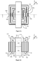
- Figure 1 a shows a perspective view of a transformer according to an exemplifying and non-limiting embodiment of the invention.
- Figure 1b shows a side-view of the transformer
- figure 1c shows a top-view of the transformer
- figure 1d shows a view of a section taken along a line A-A shown in figure 1c .
- the section plane is parallel with the xz-plane of a coordinate system 199.
- the transformer comprises a first foil winding which can be connected to an external electrical system via connection terminals 109 and 110, and a second foil winding which can be connected to the external electrical system via connection terminals 111 and 112.
- the magnetic axis of the first foil winding is substantially the same as the magnetic axis of the second foil winding and parallel with the z-axis of the coordinate system 199.
- the transformer can be, for example but not necessarily, a transformer of a switched mode power supply "SMPS" e.g. a flyback power supply or a resonance converter.
- SMPS switched mode power supply
- the first foil winding may operate as a primary winding and the second foil winding may operate as secondary winding.
- the first foil winding of the transformer is comprised of first winding portions made of first foil conductors so that the lateral direction of the first foil conductors is parallel with the magnetic axis of the first and second foil windings, i.e. parallel with the z-axis of the coordinate system 199.
- the first winding portions are illustrated in figures 1c and 1d and they are denoted with reference numbers 101 and 102.
- the second foil winding of the transformer is comprised of second winding portions made of second foil conductors so that the lateral direction of the second foil conductors is parallel with the magnetic axis of the first and second foil windings, i.e. parallel with the z-axis of the coordinate system 199.
- the second winding portions are illustrated in figures 1c and 1d and they are denoted with reference numbers 103 and 104.
- the winding portions 101-104 are interleaved in the directions perpendicular to the z-axis of the coordinate system 199 so that the winding portion 101 is the innermost one, the winding portion 103 is between the winding portions 101 and 102, the winding portion 104 is the outermost one, and the winding portion 102 is between the winding portions 103 and 104.
- the above-presented interleaving arrangement is only an example and many different interleaving arrangements are possible.
- one of the foil windings e.g.
- the second foil winding can be comprised of only one winding portion which alone constitutes the foil winding under consideration and is located between the winding portions of the other foil winding.
- at least one of the foil windings may comprise more than two winding portions interleaved with the winding portions of the other foil winding.
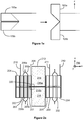
- An end-portion of the foil conductor of the winding portion 101 is split to constitute two strips 105a and 105b which have been folded to mutually opposite directions substantially parallel with the z-axis of the coordinate system 199. This is illustrated in figure 1e where lines along which the strips 105a and 105b are folded are depicted with dashed lines.
- an end-portion of the foil conductor of the winding portion 102 is split to constitute two strips 106a and 106b which have been folded to mutually opposite directions substantially parallel with the z-axis
- an end-portion of the foil conductor of the winding portion 103 is split to constitute two strips 107a and 107b which have been folded to mutually opposite directions substantially parallel with the z-axis
- an end-portion of the foil conductor of the winding portion 104 is split to constitute two strips 108a and 108b which have been folded to mutually opposite directions substantially parallel with the z-axis.
- the ends of the strips 105a and 106a are interconnected to constitute a connection bridge over the winding portion 103 as illustrated in figure 1d .
- the ends of the strips 105a and 106a can be interconnected for example by soldering or using mechanical fastening means, e.g. a bolt and a nut.
- the ends of the strips 105b and 106b are interconnected to constitute another connection bridge over the winding portion 103.
- the ends of the strips 107a and 108a are interconnected to constitute a connection bridge over the winding portion 102 as illustrated in figure 1d .
- the ends of the strips 107b and 108b are interconnected to constitute another connection bridge over the winding portion 102.
- the winding portions 101 and 102 are electrically interconnected with the two connection bridges constituted by the ends of the strips 105a and 106a and by the ends of the strips 105b and 106b.
- the two-sided electrical connection formed by the two connection bridges furthers symmetry in the distribution of current flowing in the foil conductors of the winding portions 101 and 102.
- the above-mentioned is valid also for the winding portions 103 and 104.
- the exemplifying transformer illustrated in figures 1a-1e comprises a core structure 113 having a leg surrounded by the first and second foil windings, where the longitudinal direction of the leg is substantially parallel with the magnetic axis of the first and second foil windings, i.e. parallel with the z-axis of the coordinate system 199.
- the leg is denoted with a reference number 116 in figures 1a and 1d .
- Figure 1 a shows a part of the leg 116 and figure 1d shows a section view of the leg.
- the core structure 113 comprises ferromagnetic material.
- the core structure may comprise for example ferrite or a stack of ferromagnetic steel sheets. Interleaved foil windings of the kind described above are, however, also applicable in transformers which do not comprise a ferromagnetic core structure.
- FIG. 2a shows a section view of a transformer according to an exemplifying and non-limiting embodiment of the invention.
- the transformer comprises a first foil winding which can be connected to an external electrical system via connection terminals 209 and 210, and a second foil winding which can be connected to the external electrical system via connection terminals 211 and 212.
- the first and second foil windings have a substantially same magnetic axis which is parallel with the z-axis of a coordinate system 299.
- the first foil winding of the transformer is comprised of first winding portions 201 and 202 made of first foil conductors so that the lateral direction of the first foil conductors is parallel with the magnetic axis of the first and second foil windings.
- the second foil winding of the transformer is comprised of second winding portions 203 and 204 made of second foil conductors so that the lateral direction of the second foil conductors is parallel with the magnetic axis of the first and second foil windings.
- the winding portions 201-204 are interleaved in the directions perpendicular to the z-axis of the coordinate system 299 so that the winding portion 201 is the innermost one, the winding portion 203 is between the winding portions 201 and 202, the winding portion 204 is the outermost one, and the winding portion 202 is between the winding portions 203 and 204.
- the transformer comprises a ferromagnetic core structure 213 having a leg 216 surrounded by the first and second foil windings, where the longitudinal direction of the leg is substantially parallel with the magnetic axis of the first and second foil windings, i.e. parallel with the z-axis of the coordinate system 299.
- the leg comprises two parts 216a and 216b which are separated from each other in the longitudinal direction of the leg by a non-ferromagnetic gap.
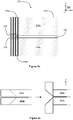
- Figure 2b shows a magnification of a part 220 of figure 2a .
- the non-ferromagnetic gap is denoted with a reference number 217.
- Each foil conductor of the foil windings comprises two mutually parallel strips a distance apart from each other in the direction of the magnetic axis so that a gap 218 between the strips is aligned with the non-ferromagnetic gap 217 so as to hinder the spreading of magnetic flux 219 caused by the non-ferromagnetic gap 217 from inducing eddy currents in the foil conductors closest to the leg 216.
- the two mutually parallel strips of the foil conductor of the winding portion 201 are denoted with reference numbers 205a and 205b.
- Figure 2c illustrates how the strips are folded to two mutually opposite directions so that the ends of the strips can be connected to the ends of the corresponding strips 206a and 206b of the winding portion 202 as illustrated in figure 2a .
- the above-described reduction of eddy currents can be achieved also by arranging only a foil conductor portion which is a part of one of the foil conductors and which is closest to the leg 216 to have two mutually parallel strips a distance apart from each other in the direction of the magnetic axis, i.e. the z-axis, so that the gap between these strips is aligned with the non-ferromagnetic gap 217.
- all the foil conductors do not need to consist of two mutually parallel strips and even the whole foil conductor which is closest to the leg does not need to consist of two mutually parallel strips.
- the choice between different alternatives is dependent on e.g. manufacture related viewpoints.
- connection terminals 109-112 and 209-212 are single sided so that they protrude in the positive z-directions of the coordinate systems 199 and 299.
- the connection terminals can be constructed for example by folding the foil conductors to form a substantially right angle so that the folding line has an angle of 45 degrees with respect to the longitudinal direction of the foil conductor under consideration. It is also possible to have two-sided connection terminals which can be constructed in the way illustrated in figure 1e or in the way illustrated figure 2c depending on the case.
- FIG 3 illustrates a transformer system according to an exemplifying and non-limiting embodiment of the invention.
- the transformer system comprises a transformer 321 and first and second circuit boards 314 and 315.
- the circuit boards are parallel with the xy-plane of a coordinate system 399.
- the transformer can be for example such as the transformer illustrated in figures 1a-1e or the transformer illustrated in figures 2a-2c .
- each of the connection terminals of the transformer 321 is soldered to an electrical conductor of the circuit board 314.
- connection terminals and/or the ends of the strips can be threaded to through-holes of the circuit boards and thereafter soldered to the electrical conductors of the circuit boards. It is also possible that the connection terminals and/or the ends of the strips are soldered or otherwise attached to connections pads on the surfaces of the circuit boards.
- a transformer according to an exemplifying and non-limiting embodiment of the invention may comprise three of more foil windings having mutually interleaved winding portions.
Landscapes
- Engineering & Computer Science (AREA)
- Power Engineering (AREA)
- Coils Of Transformers For General Uses (AREA)
- Coils Or Transformers For Communication (AREA)
Applications Claiming Priority (1)
| Application Number | Priority Date | Filing Date | Title |
|---|---|---|---|
| FI20145590A FI125524B (fi) | 2014-06-19 | 2014-06-19 | Muuntaja |
Publications (2)
| Publication Number | Publication Date |
|---|---|
| EP2958117A1 EP2958117A1 (en) | 2015-12-23 |
| EP2958117B1 true EP2958117B1 (en) | 2017-03-29 |
Family
ID=53385536
Family Applications (1)
| Application Number | Title | Priority Date | Filing Date |
|---|---|---|---|
| EP15171379.9A Active EP2958117B1 (en) | 2014-06-19 | 2015-06-10 | A foil transformer |
Country Status (6)
| Country | Link |
|---|---|
| US (1) | US9472334B2 (fi) |
| EP (1) | EP2958117B1 (fi) |
| JP (1) | JP6352858B2 (fi) |
| KR (1) | KR101797540B1 (fi) |
| CN (1) | CN105321677B (fi) |
| FI (1) | FI125524B (fi) |
Families Citing this family (10)
| Publication number | Priority date | Publication date | Assignee | Title |
|---|---|---|---|---|
| JP6352791B2 (ja) * | 2014-12-11 | 2018-07-04 | Ckd株式会社 | コイル用シート、コイル、及びコイルの製造方法 |
| JP6428742B2 (ja) * | 2016-10-12 | 2018-11-28 | オムロン株式会社 | 変圧器およびそれを備えた電力変換器 |
| JP6542499B1 (ja) * | 2017-12-27 | 2019-07-10 | 株式会社ボルター | 溶接トランス |
| CN111145988B (zh) * | 2018-11-02 | 2021-12-07 | 台达电子企业管理(上海)有限公司 | 变压器模块及功率模块 |
| CN111145996A (zh) | 2018-11-02 | 2020-05-12 | 台达电子企业管理(上海)有限公司 | 磁性元件的制造方法及磁性元件 |
| CN115359999A (zh) | 2018-11-02 | 2022-11-18 | 台达电子企业管理(上海)有限公司 | 变压器模块及功率模块 |
| US11133750B2 (en) | 2018-11-02 | 2021-09-28 | Delta Electronics (Shanghai) Co., Ltd. | Power module |
| EP3648128B1 (en) * | 2018-11-02 | 2024-01-03 | Delta Electronics (Shanghai) Co., Ltd. | Transformer module and power module |
| KR102222128B1 (ko) * | 2019-07-29 | 2021-03-03 | 현대일렉트릭앤에너지시스템(주) | 와전류손실이 저감된 변압기 및 변압기 와전류손실 계산 방법 |
| WO2023081309A1 (en) * | 2021-11-04 | 2023-05-11 | Resonant Link, Inc. | Conductive materials in alternating magnetic fields |
Family Cites Families (29)
| Publication number | Priority date | Publication date | Assignee | Title |
|---|---|---|---|---|
| US3448340A (en) * | 1965-06-29 | 1969-06-03 | Wagner Electric Corp | Transformer |
| JPS454099Y1 (fi) * | 1967-04-03 | 1970-02-25 | ||
| JPS5032730Y1 (fi) * | 1970-11-18 | 1975-09-25 | ||
| US3911332A (en) | 1971-12-29 | 1975-10-07 | George M Kunkel | Wound transformers and machine for making the same |
| US3891955A (en) | 1974-05-07 | 1975-06-24 | Westinghouse Electric Corp | Electrical inductive apparatus |
| US3939449A (en) * | 1975-01-15 | 1976-02-17 | Westinghouse Electric Corporation | Insulated transformer windings |
| JPS5840589Y2 (ja) * | 1977-05-27 | 1983-09-13 | 三菱電機株式会社 | 箔巻線の口出線引出部構造 |
| JPS53162324U (fi) * | 1977-05-27 | 1978-12-19 | ||
| US4327311A (en) * | 1979-08-31 | 1982-04-27 | Frequency, Technology, Inc. | Inductor-capacitor impedance devices and method of making the same |
| US4403205A (en) * | 1980-05-19 | 1983-09-06 | General Electric Company | Circuit arrangement for controlling transformer current |
| US4300112A (en) * | 1980-05-19 | 1981-11-10 | General Electric Company | Circuit arrangement for controlling transformer current |
| JPS58128713A (ja) * | 1982-01-27 | 1983-08-01 | Hitachi Ltd | 大電流用変圧器 |
| JPS59168614A (ja) * | 1983-03-15 | 1984-09-22 | Toshiba Corp | 箔巻変圧器 |
| JPS62274610A (ja) * | 1986-05-23 | 1987-11-28 | Toshiba Corp | 箔巻変圧器 |
| JPH03208314A (ja) * | 1990-01-10 | 1991-09-11 | Matsushita Electric Ind Co Ltd | コンバータートランス |
| JPH0722523U (ja) * | 1993-09-16 | 1995-04-21 | 日本電気精器株式会社 | 静止誘導器 |
| JPH10335156A (ja) | 1997-05-27 | 1998-12-18 | Fuji Electric Co Ltd | モールド変圧器巻線 |
| JPH114581A (ja) | 1997-06-10 | 1999-01-06 | Seiko Precision Kk | 電源回路 |
| DE29806718U1 (de) * | 1998-04-06 | 1998-11-19 | Glibitski Marks Prof Dr | Konstruktion des Transformators für Starkstrom und hohe Frequenzen |
| DE19954682C1 (de) * | 1999-11-13 | 2001-08-09 | Helmut Wollnitzke | Hochfrequenz-Transformator |
| DE10040415C1 (de) * | 2000-08-18 | 2002-01-10 | Robert Seuffer Gmbh & Co Kg | Induktives Bauelement |
| US6642830B1 (en) * | 2000-11-07 | 2003-11-04 | Iota Engineering Co. | Self lead foil winding configuration for transformers and inductors |
| US6930582B2 (en) | 2000-11-07 | 2005-08-16 | Iota Engineering Co. | Self lead foil winding configuration for transformers and inductors |
| US7701317B2 (en) * | 2004-03-29 | 2010-04-20 | The Trustees Of Dartmouth College | Low AC resistant foil winding for magnetic coils on gapped cores |
| JP2007035804A (ja) * | 2005-07-25 | 2007-02-08 | Matsushita Electric Works Ltd | 電力変換トランス |
| CN101593606B (zh) * | 2009-03-30 | 2012-02-22 | 浙江大学 | 基于柔性多层带材的全集成emi滤波器 |
| JP2012023193A (ja) * | 2010-07-14 | 2012-02-02 | Toshiba Lighting & Technology Corp | 電気装置および電気機器 |
| CN102737823A (zh) * | 2011-04-07 | 2012-10-17 | 国琏电子(上海)有限公司 | 变压器 |
| KR20140098777A (ko) | 2011-12-07 | 2014-08-08 | 엔이씨 도낀 가부시끼가이샤 | 코일, 리액터 및 코일의 형성 방법 |
-
2014
- 2014-06-19 FI FI20145590A patent/FI125524B/fi active IP Right Grant
-
2015
- 2015-06-10 EP EP15171379.9A patent/EP2958117B1/en active Active
- 2015-06-18 KR KR1020150086479A patent/KR101797540B1/ko active IP Right Grant
- 2015-06-18 US US14/742,846 patent/US9472334B2/en active Active
- 2015-06-18 JP JP2015122603A patent/JP6352858B2/ja active Active
- 2015-06-19 CN CN201510429859.9A patent/CN105321677B/zh active Active
Also Published As
| Publication number | Publication date |
|---|---|
| EP2958117A1 (en) | 2015-12-23 |
| FI125524B (fi) | 2015-11-13 |
| CN105321677A (zh) | 2016-02-10 |
| CN105321677B (zh) | 2017-08-29 |
| JP6352858B2 (ja) | 2018-07-04 |
| US9472334B2 (en) | 2016-10-18 |
| FI20145590A (fi) | 2015-11-13 |
| JP2016005004A (ja) | 2016-01-12 |
| KR101797540B1 (ko) | 2017-11-14 |
| US20150371765A1 (en) | 2015-12-24 |
| KR20150146429A (ko) | 2015-12-31 |
Similar Documents
| Publication | Publication Date | Title |
|---|---|---|
| EP2958117B1 (en) | A foil transformer | |
| CN113258788B (zh) | 具有集成磁性元件的llc谐振转换器 | |
| RU2662798C2 (ru) | Линейное электромагнитное устройство | |
| KR20150002731A (ko) | 3상 초크 | |
| EP3896707A1 (en) | Inductor assembly | |
| CN110970210A (zh) | 变压器 | |
| US20180286564A1 (en) | Power converter module | |
| CN115053305A (zh) | 具有分段绕组的电力转换器 | |
| US6100781A (en) | High leakage inductance transformer | |
| US11670444B2 (en) | Integrated magnetic assemblies and methods of assembling same | |
| CN113890361A (zh) | 电源模块 | |
| KR102605507B1 (ko) | 트랜스포머 | |
| JP2014075535A (ja) | 誘導機器 | |
| CN112041949A (zh) | 感应器装配件 | |
| KR102623872B1 (ko) | 변압기 코어 및 변압기 | |
| US11177066B2 (en) | Egg-shaped continuous coils for inductive components | |
| KR20200094423A (ko) | 트랜스포머 | |
| CN113439315A (zh) | 变压器 | |
| JPWO2019131883A1 (ja) | 溶接トランス | |
| US20220238271A1 (en) | Transformer | |
| KR102554936B1 (ko) | 평면 변압기 | |
| US20220392685A1 (en) | Inductor and dc converter including same | |
| JP7118294B2 (ja) | 変圧器および電力変換装置 | |
| KR20190014727A (ko) | 듀얼 코어 평면 트랜스포머 | |
| WO2022102611A1 (ja) | トランスユニット |
Legal Events
| Date | Code | Title | Description |
|---|---|---|---|
| PUAI | Public reference made under article 153(3) epc to a published international application that has entered the european phase |
Free format text: ORIGINAL CODE: 0009012 |
|
| AK | Designated contracting states |
Kind code of ref document: A1 Designated state(s): AL AT BE BG CH CY CZ DE DK EE ES FI FR GB GR HR HU IE IS IT LI LT LU LV MC MK MT NL NO PL PT RO RS SE SI SK SM TR |
|
| AX | Request for extension of the european patent |
Extension state: BA ME |
|
| 17P | Request for examination filed |
Effective date: 20160601 |
|
| RBV | Designated contracting states (corrected) |
Designated state(s): AL AT BE BG CH CY CZ DE DK EE ES FI FR GB GR HR HU IE IS IT LI LT LU LV MC MK MT NL NO PL PT RO RS SE SI SK SM TR |
|
| GRAP | Despatch of communication of intention to grant a patent |
Free format text: ORIGINAL CODE: EPIDOSNIGR1 |
|
| RIC1 | Information provided on ipc code assigned before grant |
Ipc: H01F 27/34 20060101ALI20160930BHEP Ipc: H01F 27/28 20060101AFI20160930BHEP Ipc: H01F 27/24 20060101ALI20160930BHEP Ipc: H01F 27/30 20060101ALI20160930BHEP |
|
| INTG | Intention to grant announced |
Effective date: 20161021 |
|
| GRAS | Grant fee paid |
Free format text: ORIGINAL CODE: EPIDOSNIGR3 |
|
| GRAA | (expected) grant |
Free format text: ORIGINAL CODE: 0009210 |
|
| AK | Designated contracting states |
Kind code of ref document: B1 Designated state(s): AL AT BE BG CH CY CZ DE DK EE ES FI FR GB GR HR HU IE IS IT LI LT LU LV MC MK MT NL NO PL PT RO RS SE SI SK SM TR |
|
| REG | Reference to a national code |
Ref country code: GB Ref legal event code: FG4D |
|
| REG | Reference to a national code |
Ref country code: CH Ref legal event code: EP |
|
| REG | Reference to a national code |
Ref country code: AT Ref legal event code: REF Ref document number: 880443 Country of ref document: AT Kind code of ref document: T Effective date: 20170415 |
|
| REG | Reference to a national code |
Ref country code: IE Ref legal event code: FG4D |
|
| REG | Reference to a national code |
Ref country code: DE Ref legal event code: R096 Ref document number: 602015001982 Country of ref document: DE |
|
| REG | Reference to a national code |
Ref country code: NL Ref legal event code: FP Ref country code: FR Ref legal event code: PLFP Year of fee payment: 3 |
|
| REG | Reference to a national code |
Ref country code: SE Ref legal event code: TRGR |
|
| PG25 | Lapsed in a contracting state [announced via postgrant information from national office to epo] |
Ref country code: LT Free format text: LAPSE BECAUSE OF FAILURE TO SUBMIT A TRANSLATION OF THE DESCRIPTION OR TO PAY THE FEE WITHIN THE PRESCRIBED TIME-LIMIT Effective date: 20170329 Ref country code: GR Free format text: LAPSE BECAUSE OF FAILURE TO SUBMIT A TRANSLATION OF THE DESCRIPTION OR TO PAY THE FEE WITHIN THE PRESCRIBED TIME-LIMIT Effective date: 20170630 Ref country code: HR Free format text: LAPSE BECAUSE OF FAILURE TO SUBMIT A TRANSLATION OF THE DESCRIPTION OR TO PAY THE FEE WITHIN THE PRESCRIBED TIME-LIMIT Effective date: 20170329 |
|
| REG | Reference to a national code |
Ref country code: AT Ref legal event code: MK05 Ref document number: 880443 Country of ref document: AT Kind code of ref document: T Effective date: 20170329 |
|
| REG | Reference to a national code |
Ref country code: NO Ref legal event code: T2 Effective date: 20170329 |
|
| PG25 | Lapsed in a contracting state [announced via postgrant information from national office to epo] |
Ref country code: BG Free format text: LAPSE BECAUSE OF FAILURE TO SUBMIT A TRANSLATION OF THE DESCRIPTION OR TO PAY THE FEE WITHIN THE PRESCRIBED TIME-LIMIT Effective date: 20170629 Ref country code: LV Free format text: LAPSE BECAUSE OF FAILURE TO SUBMIT A TRANSLATION OF THE DESCRIPTION OR TO PAY THE FEE WITHIN THE PRESCRIBED TIME-LIMIT Effective date: 20170329 Ref country code: RS Free format text: LAPSE BECAUSE OF FAILURE TO SUBMIT A TRANSLATION OF THE DESCRIPTION OR TO PAY THE FEE WITHIN THE PRESCRIBED TIME-LIMIT Effective date: 20170329 |
|
| PG25 | Lapsed in a contracting state [announced via postgrant information from national office to epo] |
Ref country code: SK Free format text: LAPSE BECAUSE OF FAILURE TO SUBMIT A TRANSLATION OF THE DESCRIPTION OR TO PAY THE FEE WITHIN THE PRESCRIBED TIME-LIMIT Effective date: 20170329 Ref country code: EE Free format text: LAPSE BECAUSE OF FAILURE TO SUBMIT A TRANSLATION OF THE DESCRIPTION OR TO PAY THE FEE WITHIN THE PRESCRIBED TIME-LIMIT Effective date: 20170329 Ref country code: CZ Free format text: LAPSE BECAUSE OF FAILURE TO SUBMIT A TRANSLATION OF THE DESCRIPTION OR TO PAY THE FEE WITHIN THE PRESCRIBED TIME-LIMIT Effective date: 20170329 Ref country code: AT Free format text: LAPSE BECAUSE OF FAILURE TO SUBMIT A TRANSLATION OF THE DESCRIPTION OR TO PAY THE FEE WITHIN THE PRESCRIBED TIME-LIMIT Effective date: 20170329 Ref country code: ES Free format text: LAPSE BECAUSE OF FAILURE TO SUBMIT A TRANSLATION OF THE DESCRIPTION OR TO PAY THE FEE WITHIN THE PRESCRIBED TIME-LIMIT Effective date: 20170329 Ref country code: RO Free format text: LAPSE BECAUSE OF FAILURE TO SUBMIT A TRANSLATION OF THE DESCRIPTION OR TO PAY THE FEE WITHIN THE PRESCRIBED TIME-LIMIT Effective date: 20170329 |
|
| PG25 | Lapsed in a contracting state [announced via postgrant information from national office to epo] |
Ref country code: SM Free format text: LAPSE BECAUSE OF FAILURE TO SUBMIT A TRANSLATION OF THE DESCRIPTION OR TO PAY THE FEE WITHIN THE PRESCRIBED TIME-LIMIT Effective date: 20170329 Ref country code: PL Free format text: LAPSE BECAUSE OF FAILURE TO SUBMIT A TRANSLATION OF THE DESCRIPTION OR TO PAY THE FEE WITHIN THE PRESCRIBED TIME-LIMIT Effective date: 20170329 Ref country code: IS Free format text: LAPSE BECAUSE OF FAILURE TO SUBMIT A TRANSLATION OF THE DESCRIPTION OR TO PAY THE FEE WITHIN THE PRESCRIBED TIME-LIMIT Effective date: 20170729 |
|
| REG | Reference to a national code |
Ref country code: DE Ref legal event code: R097 Ref document number: 602015001982 Country of ref document: DE |
|
| PG25 | Lapsed in a contracting state [announced via postgrant information from national office to epo] |
Ref country code: DK Free format text: LAPSE BECAUSE OF FAILURE TO SUBMIT A TRANSLATION OF THE DESCRIPTION OR TO PAY THE FEE WITHIN THE PRESCRIBED TIME-LIMIT Effective date: 20170329 Ref country code: MC Free format text: LAPSE BECAUSE OF FAILURE TO SUBMIT A TRANSLATION OF THE DESCRIPTION OR TO PAY THE FEE WITHIN THE PRESCRIBED TIME-LIMIT Effective date: 20170329 |
|
| PLBE | No opposition filed within time limit |
Free format text: ORIGINAL CODE: 0009261 |
|
| STAA | Information on the status of an ep patent application or granted ep patent |
Free format text: STATUS: NO OPPOSITION FILED WITHIN TIME LIMIT |
|
| 26N | No opposition filed |
Effective date: 20180103 |
|
| REG | Reference to a national code |
Ref country code: IE Ref legal event code: MM4A |
|
| PG25 | Lapsed in a contracting state [announced via postgrant information from national office to epo] |
Ref country code: IE Free format text: LAPSE BECAUSE OF NON-PAYMENT OF DUE FEES Effective date: 20170610 Ref country code: LU Free format text: LAPSE BECAUSE OF NON-PAYMENT OF DUE FEES Effective date: 20170610 |
|
| PG25 | Lapsed in a contracting state [announced via postgrant information from national office to epo] |
Ref country code: SI Free format text: LAPSE BECAUSE OF FAILURE TO SUBMIT A TRANSLATION OF THE DESCRIPTION OR TO PAY THE FEE WITHIN THE PRESCRIBED TIME-LIMIT Effective date: 20170329 |
|
| REG | Reference to a national code |
Ref country code: FR Ref legal event code: PLFP Year of fee payment: 4 |
|
| PG25 | Lapsed in a contracting state [announced via postgrant information from national office to epo] |
Ref country code: MT Free format text: LAPSE BECAUSE OF NON-PAYMENT OF DUE FEES Effective date: 20170610 |
|
| REG | Reference to a national code |
Ref country code: CH Ref legal event code: PL |
|
| PG25 | Lapsed in a contracting state [announced via postgrant information from national office to epo] |
Ref country code: LI Free format text: LAPSE BECAUSE OF NON-PAYMENT OF DUE FEES Effective date: 20180630 Ref country code: CH Free format text: LAPSE BECAUSE OF NON-PAYMENT OF DUE FEES Effective date: 20180630 |
|
| PG25 | Lapsed in a contracting state [announced via postgrant information from national office to epo] |
Ref country code: HU Free format text: LAPSE BECAUSE OF FAILURE TO SUBMIT A TRANSLATION OF THE DESCRIPTION OR TO PAY THE FEE WITHIN THE PRESCRIBED TIME-LIMIT; INVALID AB INITIO Effective date: 20150610 |
|
| PG25 | Lapsed in a contracting state [announced via postgrant information from national office to epo] |
Ref country code: CY Free format text: LAPSE BECAUSE OF FAILURE TO SUBMIT A TRANSLATION OF THE DESCRIPTION OR TO PAY THE FEE WITHIN THE PRESCRIBED TIME-LIMIT Effective date: 20170329 |
|
| PG25 | Lapsed in a contracting state [announced via postgrant information from national office to epo] |
Ref country code: MK Free format text: LAPSE BECAUSE OF FAILURE TO SUBMIT A TRANSLATION OF THE DESCRIPTION OR TO PAY THE FEE WITHIN THE PRESCRIBED TIME-LIMIT Effective date: 20170329 |
|
| REG | Reference to a national code |
Ref country code: DE Ref legal event code: R081 Ref document number: 602015001982 Country of ref document: DE Owner name: EFORE TELECOM FINLAND OY, FI Free format text: FORMER OWNER: EFORE OYJ, ESPOO, FI |
|
| REG | Reference to a national code |
Ref country code: GB Ref legal event code: 732E Free format text: REGISTERED BETWEEN 20200123 AND 20200129 |
|
| REG | Reference to a national code |
Ref country code: FI Ref legal event code: PCE Owner name: EFORE TELECOM FINLAND OY |
|
| REG | Reference to a national code |
Ref country code: BE Ref legal event code: PD Owner name: EFORE TELECOM FINLAND OY; FI Free format text: DETAILS ASSIGNMENT: CHANGE OF OWNER(S), CESSION; FORMER OWNER NAME: EFORE OYJ Effective date: 20200109 |
|
| PG25 | Lapsed in a contracting state [announced via postgrant information from national office to epo] |
Ref country code: TR Free format text: LAPSE BECAUSE OF FAILURE TO SUBMIT A TRANSLATION OF THE DESCRIPTION OR TO PAY THE FEE WITHIN THE PRESCRIBED TIME-LIMIT Effective date: 20170329 |
|
| PG25 | Lapsed in a contracting state [announced via postgrant information from national office to epo] |
Ref country code: PT Free format text: LAPSE BECAUSE OF FAILURE TO SUBMIT A TRANSLATION OF THE DESCRIPTION OR TO PAY THE FEE WITHIN THE PRESCRIBED TIME-LIMIT Effective date: 20170329 |
|
| REG | Reference to a national code |
Ref country code: NL Ref legal event code: PD Owner name: EFORE TELECOM FINLAND OY; FI Free format text: DETAILS ASSIGNMENT: CHANGE OF OWNER(S), ASSIGNMENT; FORMER OWNER NAME: EFORE OYJ Effective date: 20200518 |
|
| REG | Reference to a national code |
Ref country code: NO Ref legal event code: CHAD Owner name: EFORE TELECOM FINLAND OY, FI |
|
| PG25 | Lapsed in a contracting state [announced via postgrant information from national office to epo] |
Ref country code: AL Free format text: LAPSE BECAUSE OF FAILURE TO SUBMIT A TRANSLATION OF THE DESCRIPTION OR TO PAY THE FEE WITHIN THE PRESCRIBED TIME-LIMIT Effective date: 20170329 |
|
| PGFP | Annual fee paid to national office [announced via postgrant information from national office to epo] |
Ref country code: NO Payment date: 20230622 Year of fee payment: 9 Ref country code: NL Payment date: 20230620 Year of fee payment: 9 Ref country code: FR Payment date: 20230628 Year of fee payment: 9 Ref country code: DE Payment date: 20230620 Year of fee payment: 9 |
|
| PGFP | Annual fee paid to national office [announced via postgrant information from national office to epo] |
Ref country code: SE Payment date: 20230620 Year of fee payment: 9 Ref country code: FI Payment date: 20230621 Year of fee payment: 9 |
|
| PGFP | Annual fee paid to national office [announced via postgrant information from national office to epo] |
Ref country code: BE Payment date: 20230620 Year of fee payment: 9 |
|
| PGFP | Annual fee paid to national office [announced via postgrant information from national office to epo] |
Ref country code: IT Payment date: 20230621 Year of fee payment: 9 Ref country code: GB Payment date: 20230622 Year of fee payment: 9 |