EP2955296B1 - Procédé de fabrication d'un panneau et panneau - Google Patents
Procédé de fabrication d'un panneau et panneau Download PDFInfo
- Publication number
- EP2955296B1 EP2955296B1 EP15001461.1A EP15001461A EP2955296B1 EP 2955296 B1 EP2955296 B1 EP 2955296B1 EP 15001461 A EP15001461 A EP 15001461A EP 2955296 B1 EP2955296 B1 EP 2955296B1
- Authority
- EP
- European Patent Office
- Prior art keywords
- panel
- sealing material
- printed
- printer
- panels
- Prior art date
- Legal status (The legal status is an assumption and is not a legal conclusion. Google has not performed a legal analysis and makes no representation as to the accuracy of the status listed.)
- Active
Links
- 238000000034 method Methods 0.000 title claims description 30
- 238000004519 manufacturing process Methods 0.000 title claims description 15
- 239000003566 sealing material Substances 0.000 claims description 47
- 239000000654 additive Substances 0.000 claims description 15
- 239000011521 glass Substances 0.000 claims description 8
- 238000007639 printing Methods 0.000 claims description 7
- 230000000996 additive effect Effects 0.000 claims description 6
- 239000004575 stone Substances 0.000 claims description 5
- 239000000126 substance Substances 0.000 claims description 5
- 230000000844 anti-bacterial effect Effects 0.000 claims description 4
- 229910052593 corundum Inorganic materials 0.000 claims description 4
- 239000010431 corundum Substances 0.000 claims description 4
- OKTJSMMVPCPJKN-UHFFFAOYSA-N Carbon Chemical compound [C] OKTJSMMVPCPJKN-UHFFFAOYSA-N 0.000 claims description 3
- 229910052799 carbon Inorganic materials 0.000 claims description 3
- 229920002678 cellulose Polymers 0.000 claims description 3
- 239000001913 cellulose Substances 0.000 claims description 3
- 239000000835 fiber Substances 0.000 claims description 3
- 239000000049 pigment Substances 0.000 claims description 3
- 239000004922 lacquer Substances 0.000 claims description 2
- 229910052709 silver Inorganic materials 0.000 claims description 2
- 239000004332 silver Substances 0.000 claims description 2
- 239000003973 paint Substances 0.000 claims 1
- 239000012815 thermoplastic material Substances 0.000 claims 1
- 239000000463 material Substances 0.000 description 47
- 239000010410 layer Substances 0.000 description 13
- 239000011162 core material Substances 0.000 description 9
- 230000000694 effects Effects 0.000 description 4
- 230000003287 optical effect Effects 0.000 description 4
- 239000002023 wood Substances 0.000 description 4
- 238000010146 3D printing Methods 0.000 description 3
- 238000005299 abrasion Methods 0.000 description 3
- 238000000576 coating method Methods 0.000 description 3
- 239000011324 bead Substances 0.000 description 2
- 238000009826 distribution Methods 0.000 description 2
- 239000011094 fiberboard Substances 0.000 description 2
- 238000005304 joining Methods 0.000 description 2
- 210000002414 leg Anatomy 0.000 description 2
- 239000011241 protective layer Substances 0.000 description 2
- 230000005855 radiation Effects 0.000 description 2
- 238000007789 sealing Methods 0.000 description 2
- 229920001169 thermoplastic Polymers 0.000 description 2
- 239000004416 thermosoftening plastic Substances 0.000 description 2
- 210000000689 upper leg Anatomy 0.000 description 2
- 230000000007 visual effect Effects 0.000 description 2
- XLYOFNOQVPJJNP-UHFFFAOYSA-N water Substances O XLYOFNOQVPJJNP-UHFFFAOYSA-N 0.000 description 2
- 241000771208 Buchanania arborescens Species 0.000 description 1
- 230000001133 acceleration Effects 0.000 description 1
- 230000015572 biosynthetic process Effects 0.000 description 1
- 230000000740 bleeding effect Effects 0.000 description 1
- 230000008021 deposition Effects 0.000 description 1
- 238000006073 displacement reaction Methods 0.000 description 1
- 208000018459 dissociative disease Diseases 0.000 description 1
- 239000000975 dye Substances 0.000 description 1
- 238000005516 engineering process Methods 0.000 description 1
- 230000002708 enhancing effect Effects 0.000 description 1
- -1 for example Substances 0.000 description 1
- 239000003292 glue Substances 0.000 description 1
- 230000005484 gravity Effects 0.000 description 1
- 230000001771 impaired effect Effects 0.000 description 1
- 239000000976 ink Substances 0.000 description 1
- 238000009413 insulation Methods 0.000 description 1
- 238000003801 milling Methods 0.000 description 1
- 239000000203 mixture Substances 0.000 description 1
- 230000000149 penetrating effect Effects 0.000 description 1
- 230000035515 penetration Effects 0.000 description 1
- 239000004033 plastic Substances 0.000 description 1
- 238000004064 recycling Methods 0.000 description 1
- 239000012812 sealant material Substances 0.000 description 1
- 239000007779 soft material Substances 0.000 description 1
- 239000002344 surface layer Substances 0.000 description 1
- 230000008961 swelling Effects 0.000 description 1
Images


Classifications
-
- B—PERFORMING OPERATIONS; TRANSPORTING
- B33—ADDITIVE MANUFACTURING TECHNOLOGY
- B33Y—ADDITIVE MANUFACTURING, i.e. MANUFACTURING OF THREE-DIMENSIONAL [3-D] OBJECTS BY ADDITIVE DEPOSITION, ADDITIVE AGGLOMERATION OR ADDITIVE LAYERING, e.g. BY 3-D PRINTING, STEREOLITHOGRAPHY OR SELECTIVE LASER SINTERING
- B33Y80/00—Products made by additive manufacturing
-
- E—FIXED CONSTRUCTIONS
- E04—BUILDING
- E04F—FINISHING WORK ON BUILDINGS, e.g. STAIRS, FLOORS
- E04F15/00—Flooring
- E04F15/02—Flooring or floor layers composed of a number of similar elements
- E04F15/02038—Flooring or floor layers composed of a number of similar elements characterised by tongue and groove connections between neighbouring flooring elements
-
- E—FIXED CONSTRUCTIONS
- E04—BUILDING
- E04F—FINISHING WORK ON BUILDINGS, e.g. STAIRS, FLOORS
- E04F2201/00—Joining sheets or plates or panels
- E04F2201/01—Joining sheets, plates or panels with edges in abutting relationship
- E04F2201/0107—Joining sheets, plates or panels with edges in abutting relationship by moving the sheets, plates or panels substantially in their own plane, perpendicular to the abutting edges
- E04F2201/0115—Joining sheets, plates or panels with edges in abutting relationship by moving the sheets, plates or panels substantially in their own plane, perpendicular to the abutting edges with snap action of the edge connectors
-
- E—FIXED CONSTRUCTIONS
- E04—BUILDING
- E04F—FINISHING WORK ON BUILDINGS, e.g. STAIRS, FLOORS
- E04F2201/00—Joining sheets or plates or panels
- E04F2201/01—Joining sheets, plates or panels with edges in abutting relationship
- E04F2201/0138—Joining sheets, plates or panels with edges in abutting relationship by moving the sheets, plates or panels perpendicular to the main plane
- E04F2201/0146—Joining sheets, plates or panels with edges in abutting relationship by moving the sheets, plates or panels perpendicular to the main plane with snap action of the edge connectors
-
- E—FIXED CONSTRUCTIONS
- E04—BUILDING
- E04F—FINISHING WORK ON BUILDINGS, e.g. STAIRS, FLOORS
- E04F2201/00—Joining sheets or plates or panels
- E04F2201/01—Joining sheets, plates or panels with edges in abutting relationship
- E04F2201/0153—Joining sheets, plates or panels with edges in abutting relationship by rotating the sheets, plates or panels around an axis which is parallel to the abutting edges, possibly combined with a sliding movement
- E04F2201/0161—Joining sheets, plates or panels with edges in abutting relationship by rotating the sheets, plates or panels around an axis which is parallel to the abutting edges, possibly combined with a sliding movement with snap action of the edge connectors
-
- E—FIXED CONSTRUCTIONS
- E04—BUILDING
- E04F—FINISHING WORK ON BUILDINGS, e.g. STAIRS, FLOORS
- E04F2201/00—Joining sheets or plates or panels
- E04F2201/04—Other details of tongues or grooves
- E04F2201/044—Other details of tongues or grooves with tongues or grooves comprising elements which are not manufactured in one piece with the sheets, plates or panels but which are permanently fixedly connected to the sheets, plates or panels, e.g. at the factory
- E04F2201/049—Other details of tongues or grooves with tongues or grooves comprising elements which are not manufactured in one piece with the sheets, plates or panels but which are permanently fixedly connected to the sheets, plates or panels, e.g. at the factory wherein the elements are made of organic plastics with or without reinforcements or filling materials
Definitions
- the invention relates to a method for producing a panel, in particular a floor panel, which has an upper side, a lower side opposite the upper side and at least one side surface.
- the invention also relates to a panel produced by such a method.
- Floor panels in the form of a laminate floor form one of the world's most widely used floor coverings. While such a laminate floor originally consisted of a plurality of individual panels which had to be glued together, in the prior art the glueless laying has gained acceptance, for example, by the term "click laminate". In the case of glueless laying, however, it must be ensured that the panels, once installed, can not be moved relative to one another, even under mechanical load, as otherwise grooves and gaps may occur.
- Panels and in particular floor panels usually consist of a core, which often consists of a wood-based panel, for example a high-density fiberboard (HDF) or a medium-density fiberboard (MDF). Also other wood-based panels and materials have already been used as the core.
- HDF high-density fiberboard
- MDF medium-density fiberboard
- other wood-based panels and materials have already been used as the core.
- coatings On top of coatings are applied, on the one hand determine the visual appearance of the panel and on the other hand properties of the particular floor panels heavily loaded top. These may be the abrasion resistance enhancing layers or other protective layers.
- floor panels Through floor panels a variety of different floor materials, such as stone, tiles or real wood floors, can be modeled. It is important to simulate the joints between adjacent floor elements as realistic as possible for the visual and haptic impression of the laid floor in particular.
- additional elements inserted or clamped in designated grooves in the side surface, which form part of the surface and often only fulfill decorative tasks.
- the side surface must be sealed, which is complicated due to the often structured side surface, which optionally has a profiling, and also due to existing undercuts prone to error.
- a method for producing locking elements in which initially a basic shape, for example a simple groove is inserted into a side surface of the panel. Subsequently, a second material is applied to this basic shape created before, for example, by means of broaches the desired shape of the locking elements is introduced.
- the DE 20 2011 109 396 U1 discloses plate-shaped elements for covering surfaces in which seals are to be present between the elements, which in particular protect against moisture. These have locking elements and consist of a rubber or corresponding plastic and are, for example, molded or molded.
- a method is known in which a decorative layer is printed on the surface of a wood-based panel, which is then provided with a protective layer, for example, 0.1 to 0.2 mm thick and can be applied via a digital printer.
- the invention is therefore based on the object to improve a method for producing a panel, in particular a floor panel, so that it is easier and less expensive to produce and the possibilities of optical and haptic design of a gap between two adjacent panels are expanded.
- the invention achieves the stated object by a method for producing a panel, in particular a floor panel, which has an upper side, an underside opposite the upper side and at least one side surface, the method being characterized in that the one side surface is at least partially replaced by a 3D panel.
- Printer is printed with a sealing material, wherein a part of the sealing material forms part of the top of the panel. In a preferred embodiment, the entire side surface is printed.
- the side surface of the panel is printed by the 3D printer at least partially along the side edge of the side surface so that a portion of the applied sealing material forms part of the surface of the panel.
- the sealing material applied by the 3D printer can also be used for decorative purposes on the top of the panel.
- the side surface is completely printed at least along the side edge to the top of the panel.
- this can preferably also be done with different materials, so that can be caused by a mixture of materials to be achieved along the side edge between the respective side surface and the top of the floor panel decorative effects.
- the respective side surface can also be completely printed along the opposite side edge, that is to say the side edge extending between the underside and the side surface.
- part of the material applied by means of the 3D printer forms part of the top of the panel.
- at least one layer of the sealing material is applied with the 3D printer.
- this material is therefore visible and can be used for decorative and aesthetic purposes. Since the sealing material applied to the 3D printer is typically a different material than that used for the remainder of the top of the panel, it can be achieve a variety of different decorative effects.
- the sealing material is printed so that the part of the surface of the panel formed by the sealing material has a surface structure.
- the creation of surface structures in the area of the top formed by the sealing material is easily possible by means of the 3D printer. Even large and especially deep structures can be easily generated by means of the 3D printer, so that, for example, tile joints or joints between stone slabs can be imitated particularly simply and realistically.
- the materials used for 3D printing can also be used to create other functionalities, such as electrical conductivity, an information line or a light pipe.
- the printed sealing material which forms part of the surface of the panel, advantageously serves exclusively for decorative purposes.
- the surface structure is designed such that in the installed state of two panels a joint, in particular a stone joint, tile joint or parquet joint, is modeled.
- a profiling is introduced into the at least one side surface before the side surface is printed with the sealing material.
- the profiling is preferably a chamfer and / or a groove and / or a spring and / or a modified fold.
- the material costs for the 3D printing can be reduced, which leads to a further reduction of the production costs and to an acceleration of the method. Since 3D printers apply the material to be applied in the form of a multiplicity of thin layers, the production outlay is relatively high, especially if a relatively large amount of material is involved Proportion of the surface of the panel to be formed by the sealing material.
- the profilings are introduced into the side surface, they can contain very simple shapes, for example a simple tongue or groove. These are cost-effective, for example standard milling or sawing tools, fast and accurate to produce. Of course, more complicated profiles are possible.
- a locking element is arranged on the at least one side surface, which is at least partially printed by means of the 3D printer. Since the locking element is at least partially printed, it comes here to a sufficiently strong and stable connection between, for example, the core material of the panel, which forms part of the side surface to be printed, and the printed locking element of the sealing material or other material. Of course, different materials can be used. At the same time, a material can be chosen for the locking element, which is not the material of the core of the panel at the same time. In this way, it is possible to optimize the core material of the panel to the required properties and at the same time provide locking elements that have different properties and are optimized for the needs of locking elements. In this way, locking elements are constructed from a plurality of thin layers.
- the panel in particular the floor panel, for example, has a core of a light wood material.
- the amount of glue is reduced, whereby not only the weight but also the production costs can be reduced. Consequently, these panels are easier and easier to handle for the end user, are easier to transport and have better properties due to the possibly higher elasticity.
- mutually corresponding locking elements are each at least partially printed by means of a 3D printer on the respective side surface.
- individual or all locking elements can also be completely applied by the 3D printer. This is particularly independent of how many side surfaces locking elements are to be applied.
- the locking elements are printed with the 3D printer, it is possible to match the individual profiles particularly closely to each other. It is no longer necessary to provide for different profiles of the individual locking elements different tools that must be used as accurately as possible in the respective machine tool and in particular must be aligned as accurately as possible relative to the actual panel.
- the two corresponding locking elements designed to connect two identical panels, in particular floor panels together and to lock in at least one, preferably at least two spatial directions relative to each other.
- the locking along one direction means that a movement of the two panels relative to each other in this direction is no longer possible.
- profiles for locking elements are known from the prior art, in which the individual panels are no longer displaced in a direction perpendicular to the top of the different panels and in a direction perpendicular to the side surface of the panels, along which the two panels are interconnected can.
- displacement of the panels relative to each other along the side surface is still possible, for example.
- the method continues in an economically sensible way perform.
- the locking profiles to be used have massive proportions, they can continue to be made of the material of the panel, for example of the core. This is advantageously done by the corresponding profiling is introduced into the side surface of the panel.
- sealing materials are printed. Different 3D printers or a 3D printer with different print heads can be used. In principle, it is of course also possible to use the same print head of a 3D printer for different materials.
- the use of different materials makes it possible to optimally fulfill the different functions that are to be fulfilled by the applied material layer, and so for example the strength, elasticity and stability properties on the one hand and the optical and optionally other physical and / or chemical properties on the other hand to adapt to the particular requirements required. This increases the flexibility of the process and the variety of possible panels to be produced.
- At least a portion of the sealing material forming part of the top of the panel comprises at least one additive.
- examples are corundum, dyes and / or pigments, antibacterial substances, glass, in particular in the form of spheres and / or hollow spheres, and / or fibers, for example of cellulose, glass or carbon called.
- antibacterial substances for example, silver can be used.
- the use of corundum, glass beads and / or glass hollow spheres to improve the resistance of the surface to abrasion is known from the prior art.
- Fibers which may be cellulose, glass or carbon, for example, are used to reinforce and / or dissipate electrostatic charges. Inks and / or pigments may be used as additional optical design options in addition to the decor already on the surface of the panel.
- the at least one additive is distributed inhomogeneously in the wear layer. Since the additives can perform completely different tasks and have different properties, not all additives are needed in the entire applied sealing material or any other applied materials applied. For example, corundum and / or glass beads are of interest for improving the resistance to abrasion, in particular near the surface of the layer to be applied. In lower regions, on the other hand, they only make limited sense. In the previously known from the prior art application method of such coatings, an inhomogeneous distribution of the individual additives can not be controlled, since prefabricated application material, all additives contained in a surface layer is applied over the entire surface. Due to the particular embodiment of the present method, the individual additives can now be used optimally in accordance with requirements. As a result, the amount of additives required is reduced, which also reduces the production costs.
- the entire sealing material is applied in a single operation. This can be done for example by a plurality of print heads of a single 3D printer, which are filled with different materials and / or different additives.
- thermoplastic and / or at least one radiation-curable lacquer is used to print the at least one sealing material.
- the 3D printer can function according to the "fused deposition modeling” process, in which molten thermoplastics are applied in layers.
- a 3D printer according to the "multijet modeling” method can be used, in the curable coatings, which can be cured, for example, by UV radiation or electron radiation, is used.
- various properties can be adapted through variations of the products.
- a portion of the locking element can be made more elastic than an adjacent portion, so that, for example, when connecting the panels, the locking element can be compressed at this point. After the individual panels have been brought into their final positions, the thus compressed locking element can relax and snap, for example, in a designated undercut.
- locking elements of the prior art which are made entirely of the same material, it is possible in this way to form the particularly loaded areas of the locking elements particularly elastic and thus to avoid breakage.
- the panel with the side surface to be printed by the 3D printer is arranged upward.
- the material applied by the printer can be applied following the force of gravity, and bleeding or smearing in the uncured state is largely or even completely prevented.
- an apparatus for performing a method described herein which includes at least one 3D printer for printing at least a portion of the at least one sealant material.
- the at least one 3D printer has at least two print heads through which different materials can be printed.
- Such 3D printers are out of the ordinary the technology known in principle.
- the device also has a profiling device for introducing a profiling in at least one side surface of a panel. In this way, the profiling can first be introduced, wherein the different proportions of the profile thus introduced can subsequently be printed with the sealing material.
- the invention solves this problem by a panel, in particular a floor panel, which can be produced by one of the methods described herein.
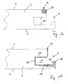
- FIGS. 1a and 1b show two panels 2, with a top 4, a top 4 opposite bottom 6 and a side surface 8.
- the panel 2 may consist in its structure between top 4 and bottom 6 of a variety of different layers, different materials and functionalities, the better Clarity because not shown here.
- a profiling 10 is introduced into the side surface 8.
- the profiling 10 consists in FIG. 1b from a groove 12 which has a short leg 14 and a long leg 16. Hatched, the sealing material 28, so the material that is applied by the 3D printer, shown.
- FIG. 1 it can be seen that a part 44 of the material 28 does not perform a locking function, but only is intended as a decorative element for the top 4. Im in FIG.
- the embodiment shown embodiment the entire side surface 8, in which a much simpler profiling 10 is introduced, covered with the sealing material 28, which has been applied over the 3D printer. Again, a portion 44 of the sealing material 28 can be seen on the top 4 of the panel 2 and provides the desired decorative effect.
- the material 28, which seals the entire side surface 8 against the ingress of moisture, also forms a locking element 18, which can engage in correspondingly corresponding locking elements.
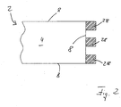
- FIG. 2 While in the FIG. 1b In the embodiment shown, the applied sealing material 28 covering the entire side surface 8 of the panel 2 and thus providing a watertight seal of the entire side surface 8 is shown in FIG. 2 illustrated that a partial printing of the side surface 8 with the sealing material 28 is possible.
- FIG. 2 a schematic plan view of the top 4 of the panel 2, in which only the in FIG. 2 right side surface 8 was printed.
- the strength of the required lock and the direction in which the lock is to act a variety of amounts of the sealing material and locking elements with different amounts of material 28 are applied to the side surface 8. The less material 8 has to be applied, the more the production of the panel 2 is accelerated. At the same time, material savings can also reduce manufacturing costs.
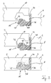
- FIG. 3 shows in the three partial views two panels 2 at different stages during the joining of the two panels 2.
- one side surface 8 of the panel 2 has no profiling, while in the side surface 8 of the left panel 2 a profiling 10 has been introduced.
- the sealing material 28 has been applied by means of the 3D printer, which forms a locking element 18 which consists of a first portion 36, a second portion 38 and a third portion 40.
- the shares may consist of different materials, wherein in the embodiment shown, the first portion 36 and the third portion 40 of a material and the second portion 38 of a different material.
- the left panel is now lowered from top to bottom to connect the two panels 2 together.
- the lower nose 42 meets the locking element 18.
- This is in the central region of FIG. 3 shown.
- the second portion 38 is compressed, so that the third portion 40 compared to the upper part of FIG. 3 is moved to the right.
- the material of the second portion 38 has in the illustrated embodiment has a much greater elasticity than the material of the first portion 36 or the third portion 40. In this way can be very easily and accurately determined which portions of the printed locking element 18 as strong and in which direction can be compressed and bent, for example, to connect two panels 2 together.
- FIG. 3 It is shown how the two panels 2 abut each other in the connected state.
- the nose 42 snaps behind the locking element 18, which causes the second portion 38 to relax and expand again.
- a slot could instead be provided which is substantially perpendicular to the top 4 and bottom 6, and the portion 40 is connected only at its end portions with the portion 36. It can be seen that the part 44 of the material 28 applied with the 3D printer does not lead to a locking, but between the two Tops 4 of the interconnected panels 2 remains visible. This can be used for decorative purposes, for example, to replicate joints between replicated tiles and / or stones.
- FIG. 4 shows, can also be produced with the present method, locking elements 18 having undercuts 19, which are open to the inside of the panel 2 out.
- the panels 2 must be erected while performing 3D printing. Although such upright positioning of the panel 2 to be printed is not necessary in the other embodiments shown, it is advantageous. In general, it is advantageous if the portion of the side surface 8 to be printed is aligned upward. With more complicated trained side surface 8, such as by pre-profiling, this can cause the panel 2 is rotated during printing or between two printing operations.
- FIG. 5 shows an enlarged section of the part 44, which is part of the top 4 of the panel 2.
- the sealing material 28 has additives 20 which are arranged in two separate regions, namely once at the lower end and once in the upper region of the sealing material 28.
- This inhomogeneous distribution of the additive 20, made possible by the use of the 3D printer, allows the additives to be optimally applied where they are needed.
- a structure 22 is present, which can also be generated by the 3D printer used. As a result, the haptic impression of this part of the upper side 4 can be influenced.
- FIGS. 6a to 6c show three different embodiments of a panel 2, in which the side surface 8 has a profiling 10 and a locking element 18. All these elements are milled or sawn out of the material of the panel in the embodiments shown Service. A part of the profiling 10 is arranged on a side edge which connects the upper side 4 with the side surface 8. Im in FIG. 6a illustrated embodiment, an L-chamfer 46 was introduced, which was filled with the sealing material 28, that results in a beveled bevel. At the in FIG. 6a not shown, the side surface 8 opposite side surface, a similar structure may be present, so that the two parts, which were prepared with the sealing material 28, form a V-joint.
- FIG. 6b A similar fugue will appear in the FIG. 6b achieved embodiment shown.
- the part of the profiling which is arranged on the side edge between the top 4 and the side surface 8, is in the FIG. 6b a simple beveled bevel 48, which has been coated with the sealing material 28.
- a V-joint is achieved in the laid state of two panels, but significantly less sealing material 28 is used.
- FIG. 6c is again an L-chamfer 46 has been introduced into the side edge between the top 4 and the side surface 8. Unlike in FIG. 6a however, this L-chamfer has not been at least partially filled up by the sealing material 28 so that a chamfered bevel results, but the two side surfaces forming the L-chamfer 46 have been printed with a layer of the sealing material 28. In the laid state of two identical panels, therefore, there is no V-groove, but a rectangular recess or groove.
Claims (13)
- Procédé de fabrication d'un panneau (2), en particulier d'un panneau de plancher, qui comprend une face supérieure (4), une face inférieure (6) opposée à la face supérieure (4), et au moins une surface latérale (8),
caractérisé en ce que
ladite au moins une surface latérale (8) est pourvue par impression au moins partiellement d'un matériau de scellement (28) au moyen d'une imprimante 3D, une partie (44) du matériau de scellement (28) formant une partie de la face supérieure (4) du panneau (2). - Procédé selon la revendication 1, caractérisé en ce que la totalité de la surface latérale (8) est pourvue d'une impression.
- Procédé selon la revendication 1 ou 2, caractérisé en ce que le matériau de scellement (28) est imprimé de telle sorte que la partie de la surface (4) du panneau qui est formée par une partie (44) du matériau de scellement (28) présente une structure surfacique (22).
- Procédé selon la revendication 3, caractérisé en ce que la structure de surface (22) est réalisée de telle sorte que dans l'état posé de deux panneaux (21), une jointure, en particulier une jointure de type pierre, de type carrelage ou de type parquet est reproduite.
- Procédé selon l'une des revendications précédentes, caractérisé en ce qu'un profilage (10) est ménagé dans ladite au moins une surface latérale (8), avant de pourvoir la surface latérale (8) d'une impression avec le matériau de scellement (28).
- Procédé selon la revendication 5, caractérisé en ce que le profilage (10) est un chanfrein et/ou une rainure (12) et/ou une languette et/ou une feuillure modifiée.
- Procédé selon l'une des revendications précédentes,
caractérisé en ce que
un élément de verrouillage (18) est agencé sur ladite au moins une surface latérale (8), qui est imprimé au moins partiellement au moyen de l'imprimante 3D. - Procédé selon la revendication 7,
caractérisé en ce que
sur au moins deux surfaces latérales (8) opposées l'une à l'autre, des éléments de verrouillage (18) conjugués sont imprimés chacun au moins partiellement au moyen de l'imprimante 3D. - Procédé selon l'une des revendications précédentes,
caractérisé en ce que
plusieurs matériaux de scellement (28) sont imprimés. - Procédé selon l'une des revendications précédentes,
caractérisé en ce que
au moins la partie (44) du matériau de scellement (28) qui forme une partie de la face supérieure (4) du panneau (2) comprend au moins un additif (20), par exemple du corindon, des colorants et/ou des pigments, des substances à effet antibactérien, du verre, en particulier sous la forme de billes et/ou de billes creuses, et/ou des fibres, par exemple en cellulose, en verre ou en carbone, et à titre de substance à effet antibactérien on utilise par exemple de l'argent. - Procédé selon l'une des revendications précédentes,
caractérisé en ce que
le matériau de scellement (28) est déposé en une seule passe de travail. - Procédé selon l'une des revendications précédentes, caractérisé en ce que pour l'impression, on utilise au moins une matière synthétique thermoplastique et/ou un vernis durcissable par irradiation.
- Panneau (2), en particulier panneau de plancher, fabriqué par un procédé selon l'une des revendications 1 à 12.
Priority Applications (2)
| Application Number | Priority Date | Filing Date | Title |
|---|---|---|---|
| EP15001461.1A EP2955296B1 (fr) | 2014-06-12 | 2015-05-15 | Procédé de fabrication d'un panneau et panneau |
| PL15001461T PL2955296T3 (pl) | 2014-06-12 | 2015-05-15 | Sposób wytwarzania panela i panel |
Applications Claiming Priority (2)
| Application Number | Priority Date | Filing Date | Title |
|---|---|---|---|
| EP14002024.9A EP2955295B1 (fr) | 2014-06-12 | 2014-06-12 | Procédé de fabrication d'un panneau |
| EP15001461.1A EP2955296B1 (fr) | 2014-06-12 | 2015-05-15 | Procédé de fabrication d'un panneau et panneau |
Publications (2)
| Publication Number | Publication Date |
|---|---|
| EP2955296A1 EP2955296A1 (fr) | 2015-12-16 |
| EP2955296B1 true EP2955296B1 (fr) | 2018-03-21 |
Family
ID=50943026
Family Applications (2)
| Application Number | Title | Priority Date | Filing Date |
|---|---|---|---|
| EP14002024.9A Active EP2955295B1 (fr) | 2014-06-12 | 2014-06-12 | Procédé de fabrication d'un panneau |
| EP15001461.1A Active EP2955296B1 (fr) | 2014-06-12 | 2015-05-15 | Procédé de fabrication d'un panneau et panneau |
Family Applications Before (1)
| Application Number | Title | Priority Date | Filing Date |
|---|---|---|---|
| EP14002024.9A Active EP2955295B1 (fr) | 2014-06-12 | 2014-06-12 | Procédé de fabrication d'un panneau |
Country Status (4)
| Country | Link |
|---|---|
| EP (2) | EP2955295B1 (fr) |
| ES (2) | ES2664105T3 (fr) |
| PL (2) | PL2955295T3 (fr) |
| PT (2) | PT2955295T (fr) |
Families Citing this family (7)
| Publication number | Priority date | Publication date | Assignee | Title |
|---|---|---|---|---|
| AT518080B1 (de) * | 2015-11-30 | 2017-07-15 | Greiner Perfoam Gmbh | Verfahren zur Herstellung eines Kfz-Innenausstattungsbauteils |
| AT518085B1 (de) * | 2015-11-30 | 2017-07-15 | Greiner Perfoam Gmbh | Verfahren zur Herstellung eines Kfz-Innenausstattungsbauteils |
| DE102016115886A1 (de) | 2016-08-26 | 2018-03-01 | Guido Schulte | Plattenförmiges Bauelement |
| US20200056380A1 (en) * | 2018-08-16 | 2020-02-20 | Zhejiang Kingdom Plastics Industry Co., Ltd. | Chamfered Plastic Floor |
| DE102019117426A1 (de) * | 2019-06-27 | 2020-12-31 | Guido Schulte | Plattenförmiges Bauelement |
| DE102019117425B4 (de) * | 2019-06-27 | 2024-05-08 | Guido Schulte | Plattenförmiges Bauelement und Verfahren zu dessen Herstellung |
| CN113502999B (zh) * | 2021-07-28 | 2022-06-10 | 广州海鸥住宅工业股份有限公司 | 拼接式3d打印防水底盘 |
Family Cites Families (4)
| Publication number | Priority date | Publication date | Assignee | Title |
|---|---|---|---|---|
| SE520084C2 (sv) * | 2001-01-31 | 2003-05-20 | Pergo Europ Ab | Förfarande för framställning av sammanfogningsprofiler |
| DE202011109396U1 (de) * | 2011-12-22 | 2012-01-26 | Jörg Paetrow | Plattenförmige Elemente zur Verkleidung von Flächen |
| CN110076060A (zh) * | 2012-07-13 | 2019-08-02 | 塞拉洛克创新股份有限公司 | 利用数码印刷/涂敷技术给建筑镶板施加涂层的方法 |
| US20140017452A1 (en) * | 2012-07-13 | 2014-01-16 | Floor Iptech Ab | Digital coating and printing |
-
2014
- 2014-06-12 PL PL14002024T patent/PL2955295T3/pl unknown
- 2014-06-12 PT PT140020249T patent/PT2955295T/pt unknown
- 2014-06-12 ES ES14002024.9T patent/ES2664105T3/es active Active
- 2014-06-12 EP EP14002024.9A patent/EP2955295B1/fr active Active
-
2015
- 2015-05-15 PT PT150014611T patent/PT2955296T/pt unknown
- 2015-05-15 PL PL15001461T patent/PL2955296T3/pl unknown
- 2015-05-15 EP EP15001461.1A patent/EP2955296B1/fr active Active
- 2015-05-15 ES ES15001461.1T patent/ES2669437T3/es active Active
Non-Patent Citations (1)
| Title |
|---|
| None * |
Also Published As
| Publication number | Publication date |
|---|---|
| EP2955296A1 (fr) | 2015-12-16 |
| PL2955296T3 (pl) | 2018-08-31 |
| PT2955296T (pt) | 2018-05-16 |
| PT2955295T (pt) | 2018-05-02 |
| EP2955295A1 (fr) | 2015-12-16 |
| PL2955295T3 (pl) | 2018-07-31 |
| ES2669437T3 (es) | 2018-05-25 |
| ES2664105T3 (es) | 2018-04-18 |
| EP2955295B1 (fr) | 2018-02-28 |
Similar Documents
| Publication | Publication Date | Title |
|---|---|---|
| EP2955296B1 (fr) | Procédé de fabrication d'un panneau et panneau | |
| EP1559850B1 (fr) | Panneau, notamment panneau de plancher | |
| EP2586929B1 (fr) | Revêtement de sol | |
| EP2250330B1 (fr) | Procédé d'application de panneaux de sol | |
| EP1593795B1 (fr) | Procédé et appareillage pour fabriquer des éléments plans, en particulier des éléments de plancher | |
| AT517360B1 (de) | Parkettdiele | |
| DE102009022483A1 (de) | Set von Paneelen, insbesondere von Fußbodenpaneelen | |
| DE10233731A1 (de) | Anordnung von Bauteilen mit Verbindungselementen | |
| DE20300291U1 (de) | Fußbodenpaneel | |
| DE202010018555U1 (de) | Paneel | |
| DE202007018662U1 (de) | Paneel, insbesondere Bodenpaneel | |
| EP2722189A1 (fr) | Procédé de fabrication d'un panneau mural ou de sol décoré | |
| EP2708675A1 (fr) | Panneau décoratif | |
| DE202019103690U1 (de) | Paneel | |
| EP1683929A2 (fr) | Procédé de fabrication d'un panneau, notamment d'un panneau de plancher, et panneau, notamment panneau de plancher | |
| WO2006063579A1 (fr) | Panneau multicouche | |
| WO2017076794A1 (fr) | Panneau et ensemble de panneaux comportant une pluralité de ces panneaux | |
| EP3112545A2 (fr) | Panneau acoustique | |
| DE102009040114A1 (de) | Paneel zur Bildung eines Belags und Verfahren zur Herstellung eines solchen Paneels | |
| EP2664730A1 (fr) | Panneau pour une pose à plat comme habillage ou revêtement avec une capacité de résistance améliorée contre l'humidité | |
| EP2918747B1 (fr) | Panneau à un chanfrein scellé au moyen d'un super-absorbeur et son procédé de fabrication | |
| DE202008001822U1 (de) | Fußbodenplatte mit Steinoberfläche | |
| EP3511160B1 (fr) | Procédé de fabrication d'un élément de revêtement et élément de revêtement | |
| DE10256501A1 (de) | Paneel, sowie Vorrichtung und Verfahren zum Herstellen eines Paneels | |
| EP2230364A1 (fr) | Plaque de sol dotée d'une surface en pierre |
Legal Events
| Date | Code | Title | Description |
|---|---|---|---|
| PUAI | Public reference made under article 153(3) epc to a published international application that has entered the european phase |
Free format text: ORIGINAL CODE: 0009012 |
|
| AK | Designated contracting states |
Kind code of ref document: A1 Designated state(s): AL AT BE BG CH CY CZ DE DK EE ES FI FR GB GR HR HU IE IS IT LI LT LU LV MC MK MT NL NO PL PT RO RS SE SI SK SM TR |
|
| AX | Request for extension of the european patent |
Extension state: BA ME |
|
| 17P | Request for examination filed |
Effective date: 20160520 |
|
| RBV | Designated contracting states (corrected) |
Designated state(s): AL AT BE BG CH CY CZ DE DK EE ES FI FR GB GR HR HU IE IS IT LI LT LU LV MC MK MT NL NO PL PT RO RS SE SI SK SM TR |
|
| RAP1 | Party data changed (applicant data changed or rights of an application transferred) |
Owner name: FLOORING TECHNOLOGIES LTD. |
|
| GRAJ | Information related to disapproval of communication of intention to grant by the applicant or resumption of examination proceedings by the epo deleted |
Free format text: ORIGINAL CODE: EPIDOSDIGR1 |
|
| GRAP | Despatch of communication of intention to grant a patent |
Free format text: ORIGINAL CODE: EPIDOSNIGR1 |
|
| STAA | Information on the status of an ep patent application or granted ep patent |
Free format text: STATUS: REQUEST FOR EXAMINATION WAS MADE |
|
| GRAP | Despatch of communication of intention to grant a patent |
Free format text: ORIGINAL CODE: EPIDOSNIGR1 |
|
| STAA | Information on the status of an ep patent application or granted ep patent |
Free format text: STATUS: GRANT OF PATENT IS INTENDED |
|
| RIC1 | Information provided on ipc code assigned before grant |
Ipc: B33Y 80/00 20150101ALI20171020BHEP Ipc: E04F 15/02 20060101AFI20171020BHEP |
|
| INTG | Intention to grant announced |
Effective date: 20171115 |
|
| GRAS | Grant fee paid |
Free format text: ORIGINAL CODE: EPIDOSNIGR3 |
|
| GRAA | (expected) grant |
Free format text: ORIGINAL CODE: 0009210 |
|
| STAA | Information on the status of an ep patent application or granted ep patent |
Free format text: STATUS: THE PATENT HAS BEEN GRANTED |
|
| AK | Designated contracting states |
Kind code of ref document: B1 Designated state(s): AL AT BE BG CH CY CZ DE DK EE ES FI FR GB GR HR HU IE IS IT LI LT LU LV MC MK MT NL NO PL PT RO RS SE SI SK SM TR |
|
| REG | Reference to a national code |
Ref country code: GB Ref legal event code: FG4D Free format text: NOT ENGLISH |
|
| REG | Reference to a national code |
Ref country code: CH Ref legal event code: EP |
|
| REG | Reference to a national code |
Ref country code: AT Ref legal event code: REF Ref document number: 981267 Country of ref document: AT Kind code of ref document: T Effective date: 20180415 |
|
| REG | Reference to a national code |
Ref country code: IE Ref legal event code: FG4D Free format text: LANGUAGE OF EP DOCUMENT: GERMAN |
|
| REG | Reference to a national code |
Ref country code: DE Ref legal event code: R096 Ref document number: 502015003489 Country of ref document: DE |
|
| REG | Reference to a national code |
Ref country code: CH Ref legal event code: NV Representative=s name: BRAUNPAT BRAUN EDER AG, CH |
|
| REG | Reference to a national code |
Ref country code: FR Ref legal event code: PLFP Year of fee payment: 4 Ref country code: PT Ref legal event code: SC4A Ref document number: 2955296 Country of ref document: PT Date of ref document: 20180516 Kind code of ref document: T Free format text: AVAILABILITY OF NATIONAL TRANSLATION Effective date: 20180510 |
|
| REG | Reference to a national code |
Ref country code: ES Ref legal event code: FG2A Ref document number: 2669437 Country of ref document: ES Kind code of ref document: T3 Effective date: 20180525 |
|
| REG | Reference to a national code |
Ref country code: SE Ref legal event code: TRGR |
|
| PG25 | Lapsed in a contracting state [announced via postgrant information from national office to epo] |
Ref country code: NO Free format text: LAPSE BECAUSE OF FAILURE TO SUBMIT A TRANSLATION OF THE DESCRIPTION OR TO PAY THE FEE WITHIN THE PRESCRIBED TIME-LIMIT Effective date: 20180621 Ref country code: FI Free format text: LAPSE BECAUSE OF FAILURE TO SUBMIT A TRANSLATION OF THE DESCRIPTION OR TO PAY THE FEE WITHIN THE PRESCRIBED TIME-LIMIT Effective date: 20180321 Ref country code: LT Free format text: LAPSE BECAUSE OF FAILURE TO SUBMIT A TRANSLATION OF THE DESCRIPTION OR TO PAY THE FEE WITHIN THE PRESCRIBED TIME-LIMIT Effective date: 20180321 Ref country code: HR Free format text: LAPSE BECAUSE OF FAILURE TO SUBMIT A TRANSLATION OF THE DESCRIPTION OR TO PAY THE FEE WITHIN THE PRESCRIBED TIME-LIMIT Effective date: 20180321 Ref country code: CY Free format text: LAPSE BECAUSE OF FAILURE TO SUBMIT A TRANSLATION OF THE DESCRIPTION OR TO PAY THE FEE WITHIN THE PRESCRIBED TIME-LIMIT Effective date: 20180321 |
|
| REG | Reference to a national code |
Ref country code: LT Ref legal event code: MG4D |
|
| PG25 | Lapsed in a contracting state [announced via postgrant information from national office to epo] |
Ref country code: BG Free format text: LAPSE BECAUSE OF FAILURE TO SUBMIT A TRANSLATION OF THE DESCRIPTION OR TO PAY THE FEE WITHIN THE PRESCRIBED TIME-LIMIT Effective date: 20180621 Ref country code: RS Free format text: LAPSE BECAUSE OF FAILURE TO SUBMIT A TRANSLATION OF THE DESCRIPTION OR TO PAY THE FEE WITHIN THE PRESCRIBED TIME-LIMIT Effective date: 20180321 Ref country code: LV Free format text: LAPSE BECAUSE OF FAILURE TO SUBMIT A TRANSLATION OF THE DESCRIPTION OR TO PAY THE FEE WITHIN THE PRESCRIBED TIME-LIMIT Effective date: 20180321 Ref country code: GR Free format text: LAPSE BECAUSE OF FAILURE TO SUBMIT A TRANSLATION OF THE DESCRIPTION OR TO PAY THE FEE WITHIN THE PRESCRIBED TIME-LIMIT Effective date: 20180622 |
|
| PG25 | Lapsed in a contracting state [announced via postgrant information from national office to epo] |
Ref country code: MT Free format text: LAPSE BECAUSE OF FAILURE TO SUBMIT A TRANSLATION OF THE DESCRIPTION OR TO PAY THE FEE WITHIN THE PRESCRIBED TIME-LIMIT Effective date: 20180321 |
|
| PG25 | Lapsed in a contracting state [announced via postgrant information from national office to epo] |
Ref country code: EE Free format text: LAPSE BECAUSE OF FAILURE TO SUBMIT A TRANSLATION OF THE DESCRIPTION OR TO PAY THE FEE WITHIN THE PRESCRIBED TIME-LIMIT Effective date: 20180321 Ref country code: AL Free format text: LAPSE BECAUSE OF FAILURE TO SUBMIT A TRANSLATION OF THE DESCRIPTION OR TO PAY THE FEE WITHIN THE PRESCRIBED TIME-LIMIT Effective date: 20180321 Ref country code: RO Free format text: LAPSE BECAUSE OF FAILURE TO SUBMIT A TRANSLATION OF THE DESCRIPTION OR TO PAY THE FEE WITHIN THE PRESCRIBED TIME-LIMIT Effective date: 20180321 |
|
| PG25 | Lapsed in a contracting state [announced via postgrant information from national office to epo] |
Ref country code: CZ Free format text: LAPSE BECAUSE OF FAILURE TO SUBMIT A TRANSLATION OF THE DESCRIPTION OR TO PAY THE FEE WITHIN THE PRESCRIBED TIME-LIMIT Effective date: 20180321 Ref country code: SK Free format text: LAPSE BECAUSE OF FAILURE TO SUBMIT A TRANSLATION OF THE DESCRIPTION OR TO PAY THE FEE WITHIN THE PRESCRIBED TIME-LIMIT Effective date: 20180321 Ref country code: SM Free format text: LAPSE BECAUSE OF FAILURE TO SUBMIT A TRANSLATION OF THE DESCRIPTION OR TO PAY THE FEE WITHIN THE PRESCRIBED TIME-LIMIT Effective date: 20180321 |
|
| REG | Reference to a national code |
Ref country code: DE Ref legal event code: R097 Ref document number: 502015003489 Country of ref document: DE |
|
| PLBE | No opposition filed within time limit |
Free format text: ORIGINAL CODE: 0009261 |
|
| STAA | Information on the status of an ep patent application or granted ep patent |
Free format text: STATUS: NO OPPOSITION FILED WITHIN TIME LIMIT |
|
| PG25 | Lapsed in a contracting state [announced via postgrant information from national office to epo] |
Ref country code: MC Free format text: LAPSE BECAUSE OF FAILURE TO SUBMIT A TRANSLATION OF THE DESCRIPTION OR TO PAY THE FEE WITHIN THE PRESCRIBED TIME-LIMIT Effective date: 20180321 Ref country code: DK Free format text: LAPSE BECAUSE OF FAILURE TO SUBMIT A TRANSLATION OF THE DESCRIPTION OR TO PAY THE FEE WITHIN THE PRESCRIBED TIME-LIMIT Effective date: 20180321 |
|
| REG | Reference to a national code |
Ref country code: IE Ref legal event code: MM4A |
|
| 26N | No opposition filed |
Effective date: 20190102 |
|
| PG25 | Lapsed in a contracting state [announced via postgrant information from national office to epo] |
Ref country code: LU Free format text: LAPSE BECAUSE OF NON-PAYMENT OF DUE FEES Effective date: 20180515 |
|
| PG25 | Lapsed in a contracting state [announced via postgrant information from national office to epo] |
Ref country code: IE Free format text: LAPSE BECAUSE OF NON-PAYMENT OF DUE FEES Effective date: 20180515 |
|
| PG25 | Lapsed in a contracting state [announced via postgrant information from national office to epo] |
Ref country code: SI Free format text: LAPSE BECAUSE OF FAILURE TO SUBMIT A TRANSLATION OF THE DESCRIPTION OR TO PAY THE FEE WITHIN THE PRESCRIBED TIME-LIMIT Effective date: 20180321 |
|
| PG25 | Lapsed in a contracting state [announced via postgrant information from national office to epo] |
Ref country code: MK Free format text: LAPSE BECAUSE OF NON-PAYMENT OF DUE FEES Effective date: 20180321 Ref country code: HU Free format text: LAPSE BECAUSE OF FAILURE TO SUBMIT A TRANSLATION OF THE DESCRIPTION OR TO PAY THE FEE WITHIN THE PRESCRIBED TIME-LIMIT; INVALID AB INITIO Effective date: 20150515 |
|
| PG25 | Lapsed in a contracting state [announced via postgrant information from national office to epo] |
Ref country code: IS Free format text: LAPSE BECAUSE OF FAILURE TO SUBMIT A TRANSLATION OF THE DESCRIPTION OR TO PAY THE FEE WITHIN THE PRESCRIBED TIME-LIMIT Effective date: 20180721 |
|
| PGFP | Annual fee paid to national office [announced via postgrant information from national office to epo] |
Ref country code: NL Payment date: 20220518 Year of fee payment: 8 |
|
| PGFP | Annual fee paid to national office [announced via postgrant information from national office to epo] |
Ref country code: IT Payment date: 20220531 Year of fee payment: 8 Ref country code: ES Payment date: 20220617 Year of fee payment: 8 |
|
| PGFP | Annual fee paid to national office [announced via postgrant information from national office to epo] |
Ref country code: PL Payment date: 20220511 Year of fee payment: 8 Ref country code: CH Payment date: 20220523 Year of fee payment: 8 Ref country code: BE Payment date: 20220518 Year of fee payment: 8 Ref country code: AT Payment date: 20220517 Year of fee payment: 8 |
|
| PGFP | Annual fee paid to national office [announced via postgrant information from national office to epo] |
Ref country code: SE Payment date: 20230315 Year of fee payment: 9 |
|
| PGFP | Annual fee paid to national office [announced via postgrant information from national office to epo] |
Ref country code: PT Payment date: 20230505 Year of fee payment: 9 Ref country code: FR Payment date: 20230517 Year of fee payment: 9 Ref country code: DE Payment date: 20230531 Year of fee payment: 9 |
|
| PGFP | Annual fee paid to national office [announced via postgrant information from national office to epo] |
Ref country code: TR Payment date: 20230510 Year of fee payment: 9 |
|
| PGFP | Annual fee paid to national office [announced via postgrant information from national office to epo] |
Ref country code: GB Payment date: 20230522 Year of fee payment: 9 |
|
| REG | Reference to a national code |
Ref country code: CH Ref legal event code: PL |
|
| REG | Reference to a national code |
Ref country code: NL Ref legal event code: MM Effective date: 20230601 Ref country code: NL Ref legal event code: FP |
|
| REG | Reference to a national code |
Ref country code: AT Ref legal event code: MM01 Ref document number: 981267 Country of ref document: AT Kind code of ref document: T Effective date: 20230515 |
|
| REG | Reference to a national code |
Ref country code: BE Ref legal event code: MM Effective date: 20230531 |
|
| PG25 | Lapsed in a contracting state [announced via postgrant information from national office to epo] |
Ref country code: LI Free format text: LAPSE BECAUSE OF NON-PAYMENT OF DUE FEES Effective date: 20230531 Ref country code: CH Free format text: LAPSE BECAUSE OF NON-PAYMENT OF DUE FEES Effective date: 20230531 Ref country code: AT Free format text: LAPSE BECAUSE OF NON-PAYMENT OF DUE FEES Effective date: 20230515 |
|
| PG25 | Lapsed in a contracting state [announced via postgrant information from national office to epo] |
Ref country code: NL Free format text: LAPSE BECAUSE OF NON-PAYMENT OF DUE FEES Effective date: 20230601 |
|
| PG25 | Lapsed in a contracting state [announced via postgrant information from national office to epo] |
Ref country code: IT Free format text: LAPSE BECAUSE OF NON-PAYMENT OF DUE FEES Effective date: 20230515 |