EP2955133B1 - Abfallentsorgungsbehälter mit pressvorrichtung - Google Patents
Abfallentsorgungsbehälter mit pressvorrichtung Download PDFInfo
- Publication number
- EP2955133B1 EP2955133B1 EP15171999.4A EP15171999A EP2955133B1 EP 2955133 B1 EP2955133 B1 EP 2955133B1 EP 15171999 A EP15171999 A EP 15171999A EP 2955133 B1 EP2955133 B1 EP 2955133B1
- Authority
- EP
- European Patent Office
- Prior art keywords
- pressing
- opening
- waste
- housing
- container
- Prior art date
- Legal status (The legal status is an assumption and is not a legal conclusion. Google has not performed a legal analysis and makes no representation as to the accuracy of the status listed.)
- Active
Links
Images




Classifications
-
- B—PERFORMING OPERATIONS; TRANSPORTING
- B65—CONVEYING; PACKING; STORING; HANDLING THIN OR FILAMENTARY MATERIAL
- B65F—GATHERING OR REMOVAL OF DOMESTIC OR LIKE REFUSE
- B65F1/00—Refuse receptacles; Accessories therefor
- B65F1/14—Other constructional features; Accessories
- B65F1/1405—Compressing means incorporated in, or specially adapted for, refuse receptacles
-
- B—PERFORMING OPERATIONS; TRANSPORTING
- B30—PRESSES
- B30B—PRESSES IN GENERAL
- B30B15/00—Details of, or accessories for, presses; Auxiliary measures in connection with pressing
- B30B15/16—Control arrangements for fluid-driven presses
- B30B15/166—Electrical control arrangements
-
- B—PERFORMING OPERATIONS; TRANSPORTING
- B30—PRESSES
- B30B—PRESSES IN GENERAL
- B30B15/00—Details of, or accessories for, presses; Auxiliary measures in connection with pressing
- B30B15/28—Arrangements for preventing distortion of, or damage to, presses or parts thereof
- B30B15/285—Arrangements for preventing distortion of, or damage to, presses or parts thereof preventing a full press stroke if there is an obstruction in the working area
-
- B—PERFORMING OPERATIONS; TRANSPORTING
- B30—PRESSES
- B30B—PRESSES IN GENERAL
- B30B9/00—Presses specially adapted for particular purposes
- B30B9/30—Presses specially adapted for particular purposes for baling; Compression boxes therefor
- B30B9/3003—Details
- B30B9/3007—Control arrangements
-
- B—PERFORMING OPERATIONS; TRANSPORTING
- B30—PRESSES
- B30B—PRESSES IN GENERAL
- B30B9/00—Presses specially adapted for particular purposes
- B30B9/30—Presses specially adapted for particular purposes for baling; Compression boxes therefor
- B30B9/3003—Details
- B30B9/3021—Press rams
-
- B—PERFORMING OPERATIONS; TRANSPORTING
- B30—PRESSES
- B30B—PRESSES IN GENERAL
- B30B9/00—Presses specially adapted for particular purposes
- B30B9/30—Presses specially adapted for particular purposes for baling; Compression boxes therefor
- B30B9/3042—Containers provided with, or connectable to, compactor means
- B30B9/3046—Containers with built-in compactor means
-
- B—PERFORMING OPERATIONS; TRANSPORTING
- B65—CONVEYING; PACKING; STORING; HANDLING THIN OR FILAMENTARY MATERIAL
- B65F—GATHERING OR REMOVAL OF DOMESTIC OR LIKE REFUSE
- B65F1/00—Refuse receptacles; Accessories therefor
- B65F1/14—Other constructional features; Accessories
- B65F1/1426—Housings, cabinets or enclosures for refuse receptacles
-
- B—PERFORMING OPERATIONS; TRANSPORTING
- B65—CONVEYING; PACKING; STORING; HANDLING THIN OR FILAMENTARY MATERIAL
- B65F—GATHERING OR REMOVAL OF DOMESTIC OR LIKE REFUSE
- B65F1/00—Refuse receptacles; Accessories therefor
- B65F1/14—Other constructional features; Accessories
- B65F2001/1494—Refuse receptacles comprising means for preventing or extinguishing fire
-
- B—PERFORMING OPERATIONS; TRANSPORTING
- B65—CONVEYING; PACKING; STORING; HANDLING THIN OR FILAMENTARY MATERIAL
- B65F—GATHERING OR REMOVAL OF DOMESTIC OR LIKE REFUSE
- B65F2210/00—Equipment of refuse receptacles
- B65F2210/104—Ashtrays
-
- B—PERFORMING OPERATIONS; TRANSPORTING
- B65—CONVEYING; PACKING; STORING; HANDLING THIN OR FILAMENTARY MATERIAL
- B65F—GATHERING OR REMOVAL OF DOMESTIC OR LIKE REFUSE
- B65F2210/00—Equipment of refuse receptacles
- B65F2210/144—Level detecting means
- B65F2210/1443—Electrical
-
- B—PERFORMING OPERATIONS; TRANSPORTING
- B65—CONVEYING; PACKING; STORING; HANDLING THIN OR FILAMENTARY MATERIAL
- B65F—GATHERING OR REMOVAL OF DOMESTIC OR LIKE REFUSE
- B65F2210/00—Equipment of refuse receptacles
- B65F2210/172—Solar cells
Definitions
- the present invention relates to a waste disposal container having a pressing device for pressing waste within the waste disposal container according to the preamble of claim 1 and a method for operating a waste disposal container having a pressing device according to claim 12.
- Cleanliness in public spaces is a central goal of cities and municipalities.
- the provision of garbage disposal containers for easy disposal of the refuse of passersby contributes significantly to achieving this goal.
- the WO2006 / 073224 describes a garbage disposal container according to the preamble of claim 1, with an automatically opening and closing door, comprising an outer housing with upper and lower doors for opening and closing upper and lower inner parts, an inner housing, which in the lower, inner part of the outer Housing, a detection unit detecting an approaching object, an upper door drive unit opening and closing the upper door in response to a signal input from the detection unit, and a control unit driving the upper door drive unit in response to the signal input from the detection unit.
- An optional press unit for compressing the waste in the inner housing is described, which comprises a pair of pivoting members, a whippen, a cross finger, a transmission and a motor. The cross fingers are attached to a lower end of the whippen, which is connected at the other end via joints with the pivot members and thereby moves up and down.
- a compaction stamp in a garbage bin performs a linear, vertical movement during the garbage compacting process.
- the compaction punch is driven by a chain drive mechanism, with the required electrical energy through photovoltaic panels on the housing of the trash compacting device is delivered.
- the recording of the waste is done by a drawer device, in which the passer by a handle has to open a separate storage compartment and then only there can deposit the waste. When closing the receiving compartment, the waste should fall into the container, in which then the compression should take place.
- the chain mechanism which drives the vertical movement of the compacting die, comprises a complicated mechanism with numerous components, which increase the manufacturing costs for the realization of the compacting device and the susceptibility to errors.
- the dimensioning and the linear, vertical movement of the compaction punch also require a relatively high height and limit the possibility of designing the shape of the cross section of the compaction punch on the dimension of the cross section of the receptacle, since otherwise a reliable compression of the contents of the container can not be guaranteed. Due to the changing position of the sun and the variable location of the waste disposal container, the fixed arrangement guarantees the photovoltaic panels at the top of the case do not optimize the use of sunlight.
- drawer device while ensuring that the hand of the passerby does not accidentally enter the compactor, requires additional action and additional contact of the passer with the housing to dispose of the waste. For reasons of hygiene, many users avoid any direct contact with a waste container in public spaces.
- the inventive waste disposal container with pressing device comprises a housing, a container, an opening in the housing, a movable securing element, a control device and a drive device operatively connected to the control device, one with the drive device coupled punch comprises a, preferably step-shaped, press plate, a long lever and a short lever.
- the press plate, the long lever and the short lever with bearings on the housing and on the press plate form a four-bar linkage (FIG. Four-joint principle according to Dubbel, paperback for mechanical engineering, Springer (1995), 18th edition, G 152 ff .).
- the ram is movable between an initial position and a maximum pressing position.
- the securing element is movable between a position releasing the opening of the housing and a position closing the opening of the housing, and according to the invention is coupled to the control device and / or the drive device.
- the coupling of the securing element with the control device and / or the drive device ensures that the securing element is in a position closing the opening of the housing during the pressing movement.
- the securing element can be locked in the position closing the opening.
- the housing may be a frame with a lining in which the container, the control device, the drive device, and the press ram can be located.
- the housing may also be a solid and supporting structure in which the container, the control device, the drive device and the press punches can be located.
- Two mounting points on the housing and two mounting points on the pressure plate can be arranged, wherein the long lever and the short lever each have a bearing point of the pressure plate with a bearing point on the housing connect.
- the mounting points on the housing can be closer together as the storage points lie on the press plate, which together with the different length of the lever leads to a complex pivoting movement of the press plate.
- the complex pivoting movement has the advantage that, in contrast to a linear pressing movement, a greater travel of the pressing plate (ie the entire pressing plate or at least parts thereof) is made possible with a constant stroke of the driving device.
- the complex pivotal movement increases the volume in the container, which moves the pressure plate during the pressing movement, and also allows the waste within the container to be brought into areas in which the waste deposited by itself hardly or less collects.
- a larger space is covered with the same dimensions of the pressing surface with the complex pivoting movement, so that the pressing surface can be smaller than the cross section of the container.
- additional levers arranged parallel to the said levers can be attached, which however do not change the degree of freedom of the pressing movement.
- the securing element in one embodiment a flap, is preferably lockable in the position closing the opening of the housing.
- the securing element may be spring-loaded in the position closing the opening of the housing and could be opened against the force of one or more springs.
- the securing element ensures that during the pressing process, the opening of the housing remains closed and thus a risk of injury by insertion of hands or arms of passers-by and by contact with the press ram is excluded.
- the system with opening in the housing and securing element allows the passerby to dispose of the waste in the waste disposal container without physical contact to the waste disposal container.
- control device and / or the drive device is electrically connected to an independent power supply.
- the fuse element can be electrically connected to the independent power supply.
- the independent power supply comprises photovoltaic elements and at least one storage element, for example a battery.
- the photovoltaic elements are, according to this embodiment, mounted on an inclined surface of a housing upper part on the upper side of the housing, wherein preferably the upper housing part comprising the inclined surface of the upper housing part is rotatable on the upper side of the upper housing part about a longitudinal axis of the housing.
- the rotatability of the upper housing part and the inclined surface offers the advantage that the photovoltaic elements can be optimally aligned to the sun, depending on the location, so that the most efficient possible energy supply is achieved.
- the throw-in opening can likewise be optimally aligned independently of the photovoltaic elements, for example towards a sidewalk or a public square, so that maximum user-friendliness is ensured.
- the housing upper part can be opened so that maintenance work on components within the waste disposal container can be carried out with a press device. For example, can be thereby easily replace a memory element arranged in the upper housing part by maintenance personnel.
- the waste disposal container with pressing device may comprise a display device attached to the outside of the housing, which preferably comprises an LED display, wherein the display device may be electrically connected to the independent power supply. This makes it possible that from the outside, for example, the service personnel, with the help of the display device, various information about the state of the waste container can be optically detected.
- the control device comprises, in a further preferred embodiment, a level control device which measures the level of the container.
- the level control device may comprise an ultrasonic measuring device.
- the control device may further include a charge level control device that measures the charge level of the storage element.
- the control device may include a compression pressure measuring device and / or a stroke length measuring device.
- the stroke length measuring device can measure the stroke length of the drive device.
- the stroke length measuring device together with the pressing pressure measuring device form a level control device and are used to determine the level of the pressed waste in a particularly simple manner.
- the display device may be connected to the charge level control device and / or the level control device be electrically connected.
- the display device may indicate information about the fill level or the charge level of the memory element through the electrical connection, for example by flashing and / or a color change of the display.
- the drive device comprises a drive cylinder, wherein the drive cylinder with the first end on the pressure plate, preferably between the bearings of the pressure plate or on one of the bearings of the pressure plate or on the long lever engages, and with the second end above the housing, preferably centrally attacks on a bracket.
- the drive cylinder may be an electric motor operated electric cylinder.
- the embodiment of the drive device as a drive cylinder reduces the susceptibility to errors compared to, for example, pressure drives or scissors mechanisms.
- the drive cylinder and designed as a four-bar press ram are compact and together take up little space, so that waste disposal containers can be realized with pressing device of small size.
- the rotatability of the inclined surface of the top of the housing can reduce the effective usable space in the housing between the ram and the top of the housing, so that the compactness of the drive mechanism and the ram provide an advantage in the design of the waste container with press device.
- the drive device may include drive mechanisms such as pneumatic drives, spindle drives, multiple drive cylinders or other electric motor drives.
- the ram comprises, in one embodiment, a step-shaped squeeze plate, the step shape being configured so that the squeeze plate is stepped down in the initial position from the, in one embodiment, frontal opening in the housing to the center of the refuse container.
- the step-shaped embodiment of the press plate allows that in the initial position of the press ram, the frontal, in one embodiment, opening in the housing remains free and an unhindered reception of waste is guaranteed.
- the step-shaped embodiment of the press plate allows, in the initial position of the press ram, the space in the housing between the ram and the inclined surface on the top of the housing to be increased, which simplifies, for example, the positioning of the storage element in said space.
- the housing has a circular cross-section perpendicular to the longitudinal axis.
- the cross section of the housing may be polygonal.
- the cross section of the container can be matched to the cross section of the housing.
- the container may have a circular cross-section perpendicular to the longitudinal axis of the housing, wherein at least two sections of the edge may be straight.
- the corresponding press plate may also have a circular shape in the plan view with at least two straight sections of the edge.
- the waste disposal container with pressing device within the housing comprises a fire extinguishing device with a fire extinguishing agent, wherein the fire extinguishing device preferably comprises a trigger and a fire extinguisher with the fire extinguishing agent.
- the waste disposal container with pressing device may comprise a communication device, with which a wireless data transmission can be performed, wherein the communication device may be electrically connected to the independent power supply.
- the securing element which is preferably a flap, in the opening of the housing releasing position with the pressure plate formed as a slanted inclined surface inclined face, which is opposite to a preferably frontal opening in the housing, wherein the inclined surface an inclination may have the longitudinal axis of the housing and may be a functional surface, which may have gradations, for example.
- the securing element preferably a shield, is disposed in the opening releasing position at least partially below the opening, wherein preferably the upper edge of the securing element rests against the lower edge of the opening.
- the securing element is mechanically connected to a pivoting device.
- the pivoting device By the pivoting device, the securing element can be pivoted.
- the fuse element can between the Opening releasing position and the position closing the opening to be pivotable, wherein the pivoting device may be electrically connected to the control device.
- the pivoting device may include a motor that can drive the pivotal movement of the securing element.
- the pivoting device or the securing element may comprise means for preventing blockages of the securing element.
- the motor of the pivoting device may comprise a load limiting device which, at a maximum load on the securing element, may interrupt the movement, for example the pivotal movement.
- the load limiting device can trigger a reversal of the movement. For example, during movement of the securing member from the opening-releasing position to the opening-closing position by the load-limiting device, the movement of the securing member can be interrupted and the securing member moved back to the opening-releasing position.
- This has the advantage that objects which, for example, are partly stuck in the opening and block the movement of the securing element, can fall into or out of the opening through the release of the opening into the opening. The risk of blocking the opening and operation of the garbage disposal container can thus be reduced.
- control device and the storage element and parts of the drive device may be in the space between the Plunger and the inclined surface to be arranged on the top of the housing.
- the arrangement of the control device, the storage element and the parts of the drive device in the space in the housing between the ram and the inclined surface on the top of the housing and the compactness of the ram and the drive device allow the realization of waste disposal containers with press device of small size.
- a small size and compactness of the garbage disposal container with press device can be advantageous in terms of vandalism, since the small size and compactness allows the production of particularly robust waste disposal containers.
- the securing element is placed in a position closing the opening of the housing and preferably locked during the pressing process in the position closing the opening, the drive device is driven by the control device, the drive device only then released is when the securing element is in the opening of the housing closing position.
- the pressing punch is moved into the pressing position which corresponds to the maximum pressing pressure, measured by the pressing pressure measuring device, wherein the movement of the pressing punch is driven by the driving device and the driving device is controlled by the control device.
- the press die is inserted into the Moved back initial position, and the securing element moves back into the opening of the housing releasing position.
- the securing element can be locked during the pressing process in the position closing the opening of the housing, for example by spring force.
- the pressing process is, according to a further embodiment of the method, triggered after a measurement of the level of the container by the level control device above a certain threshold level of the container.
- the charge level of the storage element is measured and the pressing process is triggered from a certain charge level.
- the threshold value of the level that triggers the pressing process is increased stepwise with the number of pressing operations. This has the advantage that at a low level after a certain number of pressing operations further pressing operations are suspended and thus energy can be saved. In addition, it is ensured that with a small number of pressing operations carried out and a low level of waste is pressed.
- the direction of movement of the securing element from the opening-closing / releasing position to the opening-releasing / closing position is reversed upon blocking the movement.
- the display device may indicate the level of the container and / or the charge level of the storage element by flashing and / or color change of the display.
- the communication device may transmit data, such as level and / or charge level, for example, wirelessly, to a location remote from the location of the garbage disposal bin.
- the communication device may include an insertable SIM card, wherein the data is transmitted via GSM to a location remote from the location of the garbage disposal container.
- the fire extinguishing agent of the fire extinguishing device can be dispensed into the container, which can be triggered by a trigger, the release of the fire extinguishing agent in the fire.
- a pressing operation can be initiated by the control device.
- the maximum number of pressing operations may be limited by the control device to a number, eg, 20, per day.
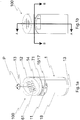
- FIG. 1a 11 shows a perspective view of one embodiment of a garbage disposal container 100 with a pressing device comprising a housing 1, a frontal opening 11, a control device (not shown in the figures), a rotatable housing upper part 14 with a sloping surface 12 and photovoltaic elements 61 on the inclined surface 12
- Upper housing part 14 is, according to the embodiment shown, rotatable about the longitudinal axis 13 in accordance with the directions indicated by the arrow P.
- a configuration of the upper housing part 14 after a rotation about a certain angle about the longitudinal axis 13 is shown by dashed lines.
- the housing 1 has a circular cross-section. Behind additional frontal openings 16, for example, ashtrays 17 may be attached.
- a frontal part of the housing 1, comprising the frontal opening 11 and the additional frontal opening 16, designed as a frontal gate 18 which can be opened to receive the waste M in the container 2 (not visible in FIG FIG. 1 ) or to carry out maintenance work.
- an LED display 71 is mounted, by means of which information on the state of the waste disposal container 100 can be optically read.
- the upper housing part 14 can preferably be opened to perform maintenance.
- FIG. 1b shows a front view of the garbage disposal container 100 with pressing device according to FIG. 1a
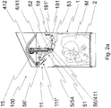
- Figures 2a-c show three sections of an embodiment of a waste disposal container 100 with pressing device along AA according to FIG. 1b , wherein the three sections differ by the different positions of the ram 5 and a securing element in the form of a flap 111 '.
- FIG. 2a shows the ram 5 in the initial position 54
- the ram 5 includes a pressing plate 51, a long lever 52 and a short lever 53.
- the pressure plate 51, the long lever 52 and the short lever 53 together with the bearings 191 and 191 'on a bearing block 19 fixed to the housing 1 and the bearings 56 and 56' on the pressing plate 51 form a four-bar linkage.
- the relative position of the bearings 191 and 191 ' is almost horizontal to each other.
- the bearings 191 and 191 ' are not directly, but on the bearing block 19 with the housing 1 operatively connected.
- the drive device 4 comprises, according to the embodiment shown, a drive cylinder 41, wherein the drive cylinder 41 engages with the first end 411 on the pressure plate 51 and the second end 412 above the housing 1 centrally on a yoke-shaped bracket 15.
- a drive cylinder 41 engages with the first end 411 on the pressure plate 51 and the second end 412 above the housing 1 centrally on a yoke-shaped bracket 15.
- FIG. 2a is the flap 111 ', in a frontal opening 11 releasing position.
- the pressing plate 51 in the initial position 54 of the ram 5 and the flap 111 'in the position releasing the opening 11 according to the embodiment shown form a functional inclined cover opposite the frontal opening 11, so that dropped through the opening 11 waste M unhindered in the container 2 can be.
- the pressing plate 51 is, according to the embodiment shown, stepped down from the frontal opening 11 to the center of the waste container, so that in the initial position 54 of the ram 5, the unhindered absorption of waste M through the
- FIG. 2b shows the ram 5 in a position between the initial position and the maximum pressing position during the pressing movement, which is driven by the drive cylinder 41, wherein the flap 111 'is in a position closing the frontal opening 11.
- the flap 111 ' is locked in the position closing the frontal opening 11 so that no access to the interior of the housing 1 is possible during the pressing movement and the risk of injury is minimized.
- the flap 111 'in a preferred embodiment may be spring biased so that the flap in the closed position is against the force of a or more springs must be opened by a damper drive.
- the flap 111 ' is thereby moved in case of failure of the damper drive by the spring force in the opening 11 closing position.
- Figure 2c shows the ram 5 in the maximum pressing position 55, wherein the stroke length of the drive cylinder 41 is at the maximum value.
- the volume of the waste M is significantly reduced in the example shown in the maximum pressing position 55 of the ram 5 compared to the initial position 54 of the ram.
- a pressing pressure measuring device 33 measures the pressing pressure.
- the position corresponding to a maximum pressing pressure can be measured. In order to avoid damage to the pressing device, the pressing movement of the press ram 5 can be interrupted upon reaching the maximum pressing pressure, even if the maximum pressing position 55 has not yet been reached.
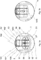
- FIG. 3a shows a plan view of a section of the waste disposal container 100 with pressing device according to the FIG. 1b along BB, wherein the ram 5 is in the initial position 54.
- the flap 111 ' is for clarity in the FIG. 3a Not shown.
- the container 2 has a circular cross section with two opposite straight sections of the edge, arranged laterally to the frontal opening 11 on.
- the pressing plate 51 has in plan view according to the in FIG. 3a embodiment shown also has a circular cross section with two opposite straight sections of the edge, preferably parallel to the straight sections the edge of the container 2, on.
- the levers 52 and 52 'each comprise two lever blades in the illustrated embodiment to increase the stability of the levers 52 and 52'.
- the levers 53 and 53 'in the embodiment shown also each comprise two lever blades.
- a plurality of parallel long lever 52 and short lever 53 can provide increased stability of the ram 5, without changing the degree of freedom of the pressing movement.
- the bearings 56 and 56 'on the pressure plate 51 are, according to the embodiment shown, formed with axes 57 and 57'.
- Additional reinforcement structures 58 for example additional ribs, may provide increased stability of the pressure plate 51.
- FIG. 3b shows a plan view according FIG. 3a with the ram in the maximum pressing position 55.
- the pressing surface of the pressing plate 51 is smaller than the depth of the container 2, wherein in the initial position 54 of the ram 5, a portion of the container 2 opposite the frontal opening 11 under the short levers 53 according to the FIG. 3a is not covered by the pressure plate 51 and in the maximum pressing position 55 of the ram 5, the area of the container 2 at the frontal opening 11 according to the FIG. 3b is not covered by the pressure plate 51.
- the pressure plate 51 has approximately the same width as the container 2. Due to the complex pivoting movement between the initial position 54 of the ram 5 and the maximum pressing position 55 of the ram 5 but during the pressing movement almost the entire depth of the container 2 is covered.
- FIG. 4a shows a perspective view of a preferred embodiment of a ram 5 in the initial position 54, comprising a pressure plate 51, two parallel arranged long lever 52 and 52 ', two mutually parallel short lever 53 and 53' and a drive cylinder 41 with central yoke-shaped holder 15th on the housing 1.
- the pressing plate 51 is, according to the embodiment shown, stepped and forms in the initial position 54 of the ram 5 a functional inclined cover.
- FIG. 4b shows the ram 5 according FIG. 4a from the same perspective as in FIG. 4a , wherein the ram 5 is now in the maximum pressing position 55.
- the bearings 56 and 56 'on the pressure plate 51 and the bearings 191 and 191' are, according to the embodiment shown, formed with axes 57, 57 ', 192 and 192'. Additional reinforcing structures 58, for example additional ribs, can provide increased stability.
- the two long levers 52 and 52 'and the two short levers 53 and 53' each comprise two lever blades, but this does not change the degree of freedom of the pressing movement.
- FIG. 5a A side view of a preferred embodiment of a ram 5 and a drive cylinder 41 with central yoke-shaped holder 15 on the housing 1 according to FIG. 4a , with the ram 5 in the initial position 54, is in FIG. 5a shown.
- the housing 1 and the housing upper part 14 are shown by dashed lines.
- the frontal opening 11 is shown open.
- Within the upper housing part 14 is the storage element 62.
- further components of the waste disposal container 100, such as parts of the drive device 4 may be placed.
- At the bearing block 19 may be a fire extinguishing device, which can give a fire extinguishing agent in the waste disposal container 100 in case of fire.
- FIG. 5b A side view of the ram 5 according to FIG. 5a , with the ram 5 in the maximum pressing position 55, is in FIG. 5b shown.
- FIG. 6a and 6b is a further embodiment of a waste disposal container according to the invention shown in longitudinal section. Shown is the top portion of a garbage disposal container where the fuse element is formed as a shield 111 " Fig. 6b shown, in a lower position, the opening 11 for injecting the waste free.
- the upper edge of the shield 111 is circumferentially projecting and abuts in this position at the lower edge of the insertion opening 11, so that it serves as Einschlippe for the waste . This ensures that the dropped waste safely enters the receptacle
- the shield 111 may serve as a chute, if necessary, since it is substantially smooth and free from interfering structures.
- the throw of waste is also not hindered by the pivoting device 9, with which the shield 111 "is mechanically connected, since the points of attack of the pivoting device on the shield 111" are arranged laterally.
- the shield 111 " which can be pivoted by means of the pivoting device 9 from a lower to an upper position closes in the latter, upper position, the insertion opening 11.
- the pivoting device 9 is not shown in the figure, preferably electrical, connection with the The connection to the control device ensures that the pressing process is only triggered when the insertion opening 11 is completely closed by the shield 111 ". Since the pivoting device 9 and its drive are arranged laterally and above the insertion opening 11, the throwing of refuse is in no way hindered. In the lower, releasing position, the shield 111 "as a chute actually aids the path of waste into the container 2.
Landscapes
- Engineering & Computer Science (AREA)
- Mechanical Engineering (AREA)
- Refuse Receptacles (AREA)
- Refuse Collection And Transfer (AREA)
Description
- Die vorliegende Erfindung betrifft einen Abfallentsorgungsbehälter mit Pressvorrichtung für die Pressung von Abfall innerhalb des Abfallentsorgungsbehälters gemäß dem Oberbegriff des Anspruchs 1 und ein Verfahren zum Betrieb eines Abfallentsorgungsbehälters mit Pressvorrichtung gemäss Anspruch 12.
- Sauberkeit im öffentlichen Raum ist ein zentrales Ziel von Städten und Gemeinden. Die Bereitstellung von Abfallentsorgungsbehältern zur einfachen Entsorgung des Abfalls der Passanten trägt wesentlich dazu bei dieses Ziel zu erreichen. Es muss dabei jedoch sichergestellt werden, dass die Abfallentsorgungsbehälter die benötigte Aufnahmefähigkeit aufweisen. Da an vielen Standorten nicht einfach beliebig voluminöse Abfallentsorgungsbehälter aufgestellt werden können, müssen die Behälter an stark frequentierten Lagen zum Teil häufig geleert werden um eine Verschmutzung des öffentlichen Raums zu verhindern.
- Die Reduzierung der manuellen Leerungsvorgänge durch Servicepersonal stellt dabei eine unbestrittene Optimierungsmöglichkeit im Unterhalt der Abfallentsorgungsbehälter sowohl für frequentierte als auch für abgelegene Standorte dar. Eine Möglichkeit einer solchen Optimierung wird durch das Pressen des Abfalls innerhalb des Abfallentsorgungsbehälters geboten, womit das effektive Aufnahmevolumen des Abfallentsorgungsbehälters erhöht und die Anzahl der benötigten Leerungen deutlich reduziert werden kann.
- Die
WO2006/073224 beschreibt einen Abfallentsorgungsbehälter gemäß dem Oberbegriff des Anspruchs 1, mit einer automatisch öffnenden und schliessenden Tür, umfassend ein äusseres Gehäuse mit oberen und unteren Türen zum Öffnen und Schliessen von oberen und unteren inneren Teilen, ein inneres Gehäuse, welche im unteren, inneren Teil des äusseren Gehäuses enthalten ist, eine Detektionseinheit, welche ein sich näherndes Objekt detektiert, eine Antriebseinheit für die obere Tür, welche die obere Tür in Reaktion auf einen Signalinput von der Detektionseinheit öffnet und schliesst, und eine Steuereinheit, welche den Antrieb der Antriebseinheit für die obere Tür in Reaktion auf den Signalinput von der Detektionseinheit steuert. Es wird eine optionale Presseinheit zur Komprimierung des Abfalls im inneren Gehäuse beschrieben, welche ein Paar von Schwenkgliedern, ein Hebeglied, Kreuzfinger, Getriebe und einen Motor umfasst. Die Kreuzfinger sind an einem unteren Ende des Hebeglieds befestigt, welches am anderen Ende über Gelenke mit den Schwenkgliedern verbunden ist und sich dadurch auf- und abwärts bewegt. - In der durch BigBelly Solar realisierten Abfallverdichtungsvorrichtung (http://www.bigbelly.com/solutions/stations/bigbelly/) vollführt ein Verdichtungsstempel in einem Abfallentsorgungsbehälter eine lineare, vertikale Bewegung während dem Verdichtungsvorgang des Abfalls. Der Verdichtungsstempel wird durch einen Kettenantriebsmechanismus angetrieben, wobei die erforderliche elektrische Energie durch Photovoltaik-Panele am Gehäuse der Abfallverdichtungsvorrichtung geliefert wird. Die Aufnahme des Abfalls geschieht durch eine Schubladenvorrichtung, bei der der Passant mittels einem Handgriff ein separates Aufnahmefach öffnen muss und dann erst darin den Abfall deponieren kann. Beim Schliessen des Aufnahmefachs soll der Abfall in den Behälter fallen, in dem dann anschliessend die Verdichtung stattfinden soll.
- Der Kettenmechanismus, der die vertikale Bewegung des Verdichtungsstempels antreibt, umfasst eine aufwändige Mechanik mit zahlreichen Bestandteilen, welche den Herstellungsaufwand für die Realisierung der Verdichtungsvorrichtung und die Fehleranfälligkeit erhöhen. Die Dimensionierung und die lineare, vertikale Bewegung des Verdichtungsstempels bedingen zudem eine relativ hohe Bauhöhe und schränken die Ausgestaltungsmöglichkeit der Form des Querschnitts des Verdichtungsstempels auf die Dimension des Querschnitts des Aufnahmebehälters ein, da ansonsten ein zuverlässiges Verdichten des Inhalts des Behälters nicht gewährleistet werden kann. Aufgrund des wechselnden Sonnenstandes und des variablen Standortes des Abfallentsorgungsbehälters garantiert die fixe Anordnung der Photovoltaik-Panele an der Oberseite des Gehäuses keine optimierte Nutzung der Sonneneinstrahlung. Die Aufnahme durch die Schubladenvorrichtung schliesslich stellt zwar sicher, dass die Hand des Passanten nicht versehentlich in die Verdichtungsvorrichtung gerät, erfordert aber eine zusätzliche Aktion und einen zusätzlichen Kontakt des Passanten mit dem Gehäuse, um den Abfall zu entsorgen. Aus hygienischen Gründen vermeiden viele Nutzer jeden direkten Kontakt mit einem Abfallbehälter im öffentlichen Raum.
- Es ist daher Aufgabe der Erfindung, einen Abfallentsorgungsbehälter mit Pressvorrichtung und ein Verfahren zum Betrieb eines Abfallentsorgungsbehälters mit Pressvorrichtung zu schaffen, welche die genannten Nachteile des Standes der Technik vermeiden.
- Diese Aufgaben werden durch den erfindungsgemässen Abfallentsorgungsbehälter mit Pressvorrichtung und das erfindungsgemässe Verfahren zum Betreiben eines Abfallentsorgungsbehälters mit Pressvorrichtung, wie sie in den Ansprüchen 1 und 12 definiert sind, gelöst. Einige bevorzugte Ausführungsformen sind in den abhängigen Ansprüchen beansprucht.
- Der erfindungsgemässe Abfallentsorgungsbehälter mit Pressvorrichtung umfasst ein Gehäuse, einen Behälter, eine Öffnung im Gehäuse, ein bewegliches Sicherungselement, eine Steuerungsvorrichtung und eine mit der Steuerungsvorrichtung wirkverbundene Antriebsvorrichtung, wobei ein mit der Antriebsvorrichtung gekoppelter Pressstempel eine, vorzugsweise stufenförmige, Pressplatte, einen langen Hebel und einen kurzen Hebel umfasst. Erfindungsgemäss bilden die Pressplatte, der lange Hebel und der kurze Hebel mit Lagerungen am Gehäuse und an der Pressplatte ein Viergelenk aus (Viergelenkprinzip gemäss Dubbel, Taschenbuch für den Maschinenbau, Springer (1995), 18. Auflage, G 152 ff.). Der Pressstempel ist zwischen einer Initialposition und einer maximalen Pressposition bewegbar. Das Sicherungselement ist zwischen einer die Öffnung des Gehäuses freigebenden Position und einer die Öffnung des Gehäuses verschliessenden Position bewegbar und gemäss der Erfindung mit der Steuerungsvorrichtung und/oder der Antriebsvorrichtung gekoppelt. Die Kopplung des Sicherungselements mit der Steuerungsvorrichtung und/oder der Antriebsvorrichtung stellt sicher, dass das Sicherungselement während der Pressbewegung in einer die Öffnung des Gehäuses verschliessenden Position ist. Vorzugsweise ist das Sicherungselement in der die Öffnung verschliessenden Position arretierbar.
- Das Gehäuse kann ein Rahmen mit einer Verkleidung sein, in welchem sich der Behälter, die Steuerungsvorrichtung, die Antriebsvorrichtung, und der Pressstempel befinden können. Das Gehäuse kann auch eine massive und tragende Struktur sein, in welchem sich der Behälter, die Steuerungsvorrichtung, die Antriebsvorrichtung und der Pressstempel befinden können.
- Zwei Lagerungspunkte am Gehäuse und zwei Lagerungspunkte an der Pressplatte können angeordent sein, wobei der lange Hebel und der kurze Hebel jeweils einen Lagerungspunkt der Pressplatte mit einem Lagerungspunkt am Gehäuse verbinden. Die Lagerungspunkte am Gehäuse können näher beieinander als die Lagerungspunkte an der Pressplatte liegen, was zusammen mit der unterschiedlichen Länge der Hebel zu einer komplexen Schwenkbewegung der Pressplatte führt. Die komplexe Schwenkbewegung hat den Vorteil, dass im Gegensatz zu einer linearen Pressbewegung ein grösserer Weg der Pressplatte (d.h. der ganzen Pressplatte oder zumindest Teilen davon) bei gleichbleibendem Hub der Antriebsvorrichtung ermöglicht wird. Die komplexe Schwenkbewegung vergrössert das Volumen im Behälter, durch das die Pressplatte bei der Pressbewegung bewegt wird und ermöglicht zudem den Abfall innerhalb des Behälters in Bereiche zu bringen, in denen sich der eingeworfene Abfall von alleine kaum oder weniger sammelt. Im Vergleich zu einer linearen Bewegung wird bei gleichen Dimensionen der Pressfläche mit der komplexen Schwenkbewegung ein grösserer Raum abgedeckt, so dass die Pressfläche kleiner als der Querschnitt des Behälters sein kann. Für eine erhöhte Stabilität können parallel zu den genannten Hebeln angeordnete zusätzliche Hebel angebracht werden, welche den Freiheitsgrad der Pressbewegung aber nicht ändern.
- Das Sicherungselement, in einer Ausführungsform eine Klappe, ist vorzugsweise in der die Öffnung des Gehäuses verschliessenden Position arretierbar. Das Sicherungselement kann federkraftbeaufschlagt in der die Öffnung des Gehäuses verschliessenden Position sein und könnte gegen die Kraft von einer oder mehreren Federn geöffnet werden.
- Das Sicherungselement stellt sicher, dass während dem Pressvorgang die Öffnung des Gehäuses verschlossen bleibt und somit eine Verletzungsgefahr durch Einführen von Händen oder Armen von Passanten und durch Kontakt mit dem Pressstempel ausgeschlossen wird. Das System mit Öffnung im Gehäuse und Sicherungselement, ermöglicht dem Passanten ohne physischen Kontakt zum Abfallentsorgungsbehälter den Abfall im Abfallentsorgungsbehälter zu entsorgen.
- Gemäss einer bevorzugten Ausführungsform ist die Steuerungsvorrichtung und/oder die Antriebsvorrichtung mit einer unabhängigen Spannungsversorgung elektrisch verbunden. Auch kann das Sicherungselement mit der unabhängigen Spannungsversorgung elektrisch verbunden werden.
- Bei einer bevorzugten Ausführungsform umfasst die unabhängige Spannungsversorgung Photovoltaikelemente und mindestens ein Speicherelement, zum Beispiel eine Batterie. Die Photovoltaikelemente sind, gemäss dieser Ausführungsform, auf einer geneigten Oberfläche eines Gehäuseoberteils auf der Oberseite des Gehäuses angebracht, wobei vorzugsweise das Gehäuseoberteil umfassend die geneigte Oberfläche des Gehäuseoberteils auf der Oberseite des Gehäuseoberteils um eine Längsachse des Gehäuses drehbar ist. Die Drehbarkeit des Gehäuseoberteils und der geneigten Oberfläche bietet den Vorteil, dass die Photovoltaikelemente je nach Standort optimal zur Sonne hin ausgerichtet werden können, so dass eine möglichst effiziente Energieversorgung erreicht wird. Die Einwurföffnung kann hingegen unabhängig von den Photovoltaikelementen ebenfalls optimal ausgerichtet werden, zum Beispiel zu einem Gehweg oder einem öffentlichen Platz hin, so dass eine maximale Nutzerfreundlichkeit gewährleistet ist. Das Gehäuseoberteil kann geöffnet werden, so dass Wartungsarbeiten an Bestandteilen innerhalb des Abfallentsorgungsbehälters mit Pressvorrichtung durchgeführt werden können. Zum Beispiel lässt sich dadurch ein im Gehäuseoberteil angeordnetes Speicherelement durch Wartungspersonal auf einfache Weise auswechseln.
- Der Abfallentsorgungsbehälter mit Pressvorrichtung kann eine an der Aussenseite des Gehäuses angebrachte Anzeigevorrichtung umfassen, die vorzugsweise eine LED-Anzeige umfasst, wobei die Anzeigevorrichtung mit der unabhängigen Spannungsversorgung elektrisch verbunden sein kann. Dadurch wird ermöglicht, dass von aussen, zum Beispiel vom Servicepersonal, mit Hilfe der Anzeigevorrichtung verschiedene Informationen über den Zustand des Abfallentsorgungsbehälters optisch erfasst werden können.
- Die Steuerungsvorrichtung umfasst, bei einer weiteren bevorzugten Ausführungsform, eine Füllstandskontrollvorrichtung, die den Füllstand des Behälters misst. Die Füllstandskontrollvorrichtung kann eine Ultraschallmessvorrichtung umfassen. Die Steuerungsvorrichtung kann weiter eine Ladestandskontrollvorrichtung umfassen, die den Ladestand des Speicherelements misst. Auch kann die Steuerungsvorrichtung eine Pressdruckmessvorrichtung und/oder eine Hublängenmessvorrichtung umfassen. Die Hublängenmessvorrichtung kann die Hublänge der Antriebsvorrichtung messen. Vorzugsweise kann die Hublängenmessvorrichtung zusammen mit der Pressdruckmessvorrichtung eine Füllstandskontrollvorrichtung ausbilden und dazu benutzt werden, den Füllstand des gepressten Abfalls auf eine besonders einfache Weise zu ermitteln. Die Anzeigevorrichtung kann mit der Ladestandskontrollvorrichtung und/oder der Füllstandskontrollvorrichtung elektrisch verbunden sein. Die Anzeigevorrichtung kann durch die elektrische Verbindung Informationen über den Füllstand oder den Ladestand des Speicherelements anzeigen, zum Beispiel durch Blinken und/oder einer Farbänderung der Anzeige.
- Gemäss einer bevorzugten Ausführungsform umfasst die Antriebsvorrichtung einen Antriebszylinder, wobei der Antriebszylinder mit dem ersten Ende an der Pressplatte, vorzugsweise zwischen den Lagerungen der Pressplatte oder an einem der Lagerungen der Pressplatte oder am langen Hebel, angreift und mit dem zweiten Ende oberhalb am Gehäuse, vorzugsweise zentral an einer Halterung angreift. Der Antriebszylinder kann ein elektromotorisch betriebener Elektrozylinder sein. Die Ausführungsform der Antriebsvorrichtung als Antriebszylinder reduziert die Fehleranfälligkeit im Vergleich zu zum Beispiel Drucckissenantrieben oder Scherenmechanismen. Der Antriebszylinder und der als Viergelenk ausgestaltete Pressstempel sind kompakt und nehmen zusammen wenig Platz ein, so dass Abfallentsorgungsbehälter mit Pressvorrichtung von kleiner Baugrösse realisiert werden können. Gerade die Drehbarkeit der geneigten Oberfläche des Oberteils des Gehäuses kann den effektiv nutzbaren Raum im Gehäuse zwischen dem Pressstempel und der Oberseite des Gehäuses reduzieren, so dass die Kompaktheit des Antriebsmechanismus und des Pressstempels einen Vorteil in der Ausgestaltung des Abfallentsorgungsbehälters mit Pressvorrichtung bieten.
- Die Antriebsvorrichtung kann Antriebsmechanismen wie zum Beispiel pneumatische Antriebe, Spindelantriebe, mehrere Antriebszylinder oder weitere elektromotorische Antriebe umfassen.
- Der Pressstempel umfasst, bei einer Ausführungsform, eine stufenförmige Pressplatte, wobei die Stufenform so ausgestaltet ist, dass die Pressplatte in der Initialposition ausgehend von der, in einer Ausführungsform frontalen, Öffnung im Gehäuse zur Mitte des Abfallentsorgungsbehälters abwärts gestuft ist. Die stufenförmige Ausführungsform der Pressplatte ermöglicht, dass in der Initialposition des Pressstempels die, in einer Ausführungsform frontale, Öffnung im Gehäuse frei bleibt und eine ungehinderte Aufnahme von Abfall garantiert ist. Ausserdem ermöglicht die stufenförmige Ausführungsform der Pressplatte, dass in der Initialposition des Pressstempels der Raum im Gehäuse zwischen dem Pressstempel und der geneigten Oberfläche auf der Oberseite des Gehäuses vergrössert wird, was zum Beispiel die Positionierung des Speicherelements im genannten Raum vereinfacht.
- Bei einer bevorzugten Ausführungsform weist das Gehäuse senkrecht zur Längsachse einen kreisförmigen Querschnitt auf. Der Querschnitt des Gehäuses kann polygonal sein. Der Querschnitt des Behälters kann auf den Querschnitt des Gehäuses abgestimmt sein. Der Behälter kann senkrecht zur Längsachse des Gehäuses einen kreisförmigen Querschnitt aufweisen, wobei mindestens zwei Teilabschnitte des Randes gerade sein können. Die entsprechende Pressplatte kann in der Draufsicht ebenfalls eine kreisförmige Form mit mindestens zwei geraden Teilabschnitten des Randes aufweisen.
- Gemäss einer bevorzugten Ausführungsform umfasst der Abfallentsorgungsbehälter mit Pressvorrichtung innerhalb des Gehäuses eine Brandlöschvorrichtung mit einem Brandlöschmittel, wobei die Brandlöschvorrichtung vorzugsweise einen Auslöser und eine Brandlöschkapsel mit dem Brandlöschmittel umfasst.
- Der Abfallentsorgungsbehälter mit Pressvorrichtung kann eine Kommunikationsvorrichtung umfassen, mit weicher eine drahtlose Datenübertragung vorgenommen werden kann, wobei die Kommunikationsvorrichtung mit der unabhängigen Spannungsversorgung elektrisch verbunden sein kann.
- Gemäss einer weiteren bevorzugten Ausführungsform bilden das Sicherungselement, welches vorzugsweise eine Klappe ist, in der die Öffnung des Gehäuses freigebenden Position mit der Pressplatte einen als Schrägdeckel ausgebildete Schrägfläche, der sich gegenüberliegend zu einer vorzugsweise frontalen Öffnung im Gehäuse befindet, wobei die Schrägfläche eine Neigung gegenüber der Längsachse des Gehäuses aufweisen kann und eine funktionale Fläche sein kann, die zum Beispiel Stufungen aufweisen kann.
- In einer Ausführungsform ist das Sicherungselement, vorzugsweise ein Schild, in der die Öffnung freigebenden Position mindestens teilweise unterhalb der Öffnung angeordnet, wobei vorzugsweise der obere Rand des Sicherungselements am unteren Rand der Öffnung anliegt.
- In einer Ausführungsform ist das Sicherungselement mit einer Schwenkvorrichtung mechanisch verbunden. Durch die Schwenkvorrichtung kann das Sicherungselement geschwenkt werden. Das Sicherungselement kann zwischen der die Öffnung freigebenden Position und der die Öffnung verschliessenden Position schwenkbar sein, wobei die Schwenkvorrichtung mit der Steuerungsvorrichtung elektrisch verbunden sein kann. Dies hat den Vorteil, dass die Schwenkbewegung des Sicherungselements elektrisch gesteuert werden kann. Die Schwenkvorrichtung kann einen Motor umfassen, welche die Schwenkbewegung des Sicherungselements antreiben kann.
- Die Schwenkvorrichtung oder das Sicherungselement kann Mittel zur Verhinderung von Blockaden des Sicherungselements umfassen. Zum Beispiel kann der Motor der Schwenkvorrichtung eine Lastbegrenzungsvorrichtung umfassen, welche bei einer maximalen Last auf das Sicherungselement die Bewegung, zum Beispiel die Schwenkbewegung, unterbrechen kann. Die Lastbegrenzungsvorrichtung kann eine Umkehr der Bewegung auslösen. Zum Beispiel kann während der Bewegung des Sicherungselements von der die Öffnung freigebenden Position in die die Öffnung verschliessende Position durch die Lastbegrenzungsvorrichtung die Bewegung des Sicherungselements unterbrochen werden und das Sicherungselement in die die Öffnung freigebende Position zurückbewegt werden. Dies hat den Vorteil, dass Gegenstände, welche zum Beispiel teilweise in der Öffnung stecken und die Bewegung des Sicherungselements blockieren, durch die Freigabe der Öffnung in die Öffnung hinein- oder aus der Öffnung herausfallen können. Das Risiko einer Blockierung der Öffnung und des Betriebs des Abfallentsorgungsbehälters kann so reduziert werden.
- Die Steuerungsvorrichtung und das Speicherelement und Teile der Antriebsvorrichtung können im Raum zwischen dem Pressstempel und der geneigten Oberfläche auf der Oberseite des Gehäuses angeordnet sein.
- Die Anordnung der Steuerungsvorrichtung, des Speicherelements und der Teile der Antriebsvorrichtung im Raum im Gehäuse zwischen dem Pressstempel und der geneigten Oberfläche auf der Oberseite des Gehäuses und die Kompaktheit des Pressstempels und der Antriebsvorrichtung erlauben die Realisierung von Abfallentsorgungsbehältern mit Pressvorrichtung von kleiner Baugrösse. Eine kleine Baugrösse und Kompaktheit des Abfallentsorgungsbehälters mit Pressvorrichtung kann vorteilhaft in Bezug auf die Vandalensicherheit sein, da die kleine Baugrösse und die Kompaktheit die Herstellung von besonders robusten Abfallentsorgungsbehältern erlaubt.
- Beim erfindungsgemässen Verfahren zum Pressen von Abfall mit einem Abfallentsorgungsbehälter mit Pressvorrichtung wird das Sicherungselement in eine die Öffnung des Gehäuses verschliessende Position gebracht und vorzugsweise während dem Pressvorgang in der die Öffnung verschliessenden Position arretiert, die Antriebsvorrichtung durch die Steuerungsvorrichtung angesteuert, wobei die Antriebsvorrichtung nur dann freigegeben wird, wenn das Sicherungselement in der die Öffnung des Gehäuses verschliessenden Position ist. Der Pressstempel wird beim erfindungsgemässen Verfahren in die Pressposition, die dem maximalen Pressdruck, gemessen durch die Pressdruckmessvorrichtung, entspricht, bewegt, wobei die Bewegung des Pressstempels durch die Antriebsvorrichtung angetrieben und die Antriebsvorrichtung durch die Steuerungsvorrichtung gesteuert wird. Schliesslich wird, beim erfindungsgemässen Verfahren, der Pressstempel in die Initialposition zurückbewegt, und das Sicherungselement in die die Öffnung des Gehäuses freigebende Position zurückbewegt.
- Das Sicherungselement kann während dem Pressvorgang in der die Öffnung des Gehäuses verschliessenden Position, zum Beispiel federkraftbeaufschlagt, arretiert werden.
- Der Pressvorgang wird, gemäss einer weiteren Ausführungsform des Verfahrens, nach einer Messung des Füllstandes des Behälters durch die Füllstandskontrollvorrichtung ab einem bestimmten Schwellenwert des Füllstandes des Behälters ausgelöst. Vorzugsweise wird auch der Ladestand des Speicherelements gemessen und der Pressvorgang ab einem bestimmten Ladestand ausgelöst.
- Bei einer bevorzugten Ausführungsform des Verfahrens wird der Schwellenwert des Füllstandes, der den Pressvorgang auslöst, stufenweise mit der Anzahl der Pressvorgänge erhöht. Dies hat den Vorteil, dass bei einem geringen Füllstand nach einer bestimmten Anzahl von Pressvorgängen weitere Pressvorgänge ausgesetzt werden und damit Energie gespart werden kann. Ausserdem wird sicher gestellt, dass bei einer noch geringen Anzahl von durchgeführten Pressvorgängen und einem geringen Füllstand der Abfall gepresst wird.
- Bei einer Ausführungsform des Verfahrens wird die Richtung der Bewegung des Sicherungselements von der die Öffnung verschliessenden/freigebenden Position in die die Öffnung freigebende/verschliessende Position bei einer Blockierung der Bewegung umgekehrt.
- Die Anzeigevorrichtung kann den Füllstand des Behälters und/oder den Ladestand des Speicherelements durch Blinken und/oder Farbänderung der Anzeige anzeigen.
- Die Kommunikationsvorrichtung kann Daten, wie zum Beispiel zum Füllstand und/oder zum Ladestand, zum Beispiel drahtlos, an einen vom Standort des Abfallentsorgungsbehälters entfernten Ort übertragen.
- Die Kommunikationsvorrichtung kann eine einsetzbare SIM-Karte, wobei die Daten über GSM an einen vom Standort des Abfallentsorgungsbehälters entfernten Ort übermittelt werden, umfassen.
- Bei einem Brandfall kann das Brandlöschmittel der Brandlöschvorrichtung in den Behälter abgegeben werden, wobei durch einen Auslöser die Abgabe des Brandlöschmittels in der Brandkapsel ausgelöst werden kann.
- In voreinstellbaren Intervallen, zum Beispiel alle 15 Minuten, kann durch die Steuervorrichtung ein Pressvorgang ausgelöst werden. Die maximale Anzahl an Pressvorgängen kann durch die Steuervorrichtung auf eine Anzahl, z.B. auf 20, pro Tag beschränkt werden.
- Ausführungsformen der Erfindung werden anhand der nachfolgenden Figuren und der dazugehörigen Beschreibungen näher erläutert. Es zeigen:
- Fig. 1a
- eine perspektivische Ansicht einer Ausführungsform eines Abfallentsorgungsbehälters mit Pressvorrichtung umfassend ein Gehäuse mit frontaler Öffnung, einem drehbaren Gehäuseoberteil, wobei das um einen bestimmten Winkel gedrehte Gehäuseoberteil strichliniert gezeigt ist;
- Fig. 1b
- eine Frontalansicht des Abfallentsorgungsbehälters gemäss
Fig. 1a ; - Fig. 2a
- einen Schnitt einer Ausführungsform eines Abfallentsorgungsbehälters mit Pressvorrichtung gemäss
Fig. 1b entlang A-A umfassend einen Pressstempel in der Initialposition und einer Klappe in der die frontale Öffnung des Gehäuses freigebenden Position; - Fig. 2b
- einen Schnitt des Abfallentsorgungsbehälters gemäss
Fig. 2a mit geschlossener Klappe und mit dem Pressstempel in einer Position zwischen der Initialposition und der maximalen Pressposition; - Fig. 2c
- einen Schnitt des Abfallentsorgungsbehälters gemäss
Fig. 2a und2b mit geschlossener Klappe und mit dem Pressstempel in der maximalen Pressposition; - Fig. 3a
- eine Draufsicht eines Schnitts eines Abfallentsorgungsbehälters gemäss
Fig. 1b entlang B-B mit dem Pressstempel in der Initialposition; - Fig. 3b
- eine Draufsicht eines des Abfallentsorgungsbehälters gemäss
Fig. 3a mit dem Pressstempel in der maximalen Pressposition; - Fig. 4a
- eine perspektivische Ansicht einer Ausführungsform eines Pressstempels in der Initialposition und eines Antriebszylinders mit zentraler Halterung am Gehäuse, wobei die übrigen Teile des Abfallentsorgungsbehälters weggelassen sind;
- Fig. 4b
- eine perspektivische Ansicht der Ausführungsform eines Pressstempels gemäss
Fig. 4a in der gleichen Perspektive mit dem Pressstempel in der maximalen Pressposition; - Fig. 5a
- eine Seitenansicht der Ausführungsform eines Pressstempels und eines Antriebszylinders mit zentraler Halterung am Gehäuse gemäss
Fig. 4a mit dem Pressstempel in der Initialposition, wobei das Gehäuse strichliniert gezeigt ist; - Fig. 5b
- eine Seitenansicht der Ausführungsform gemäss
Fig. 5a mit dem Pressstempel in der maximalen Pressposition; - Fig. 6a
- einen Längsschnitt durch den oberen Bereich einer weiteren Ausführungsform eines Abfallbehälters mit einem Sicherungselement in Form eines Schildes in einer oberen die Einwurföffnung verschliessenden Position; und
- Fig. 6b
- die Ansicht gemäss
Fig. 6a , wobei der Schild nun in einer unteren, die Einwurföffnung freigebenden Position dargestellt ist. - Die vorliegende detaillierte Beschreibung legt im Zusammenhang mit den begleitenden Figuren Ausführungsformen der Erfindung dar und soll zu einem besseren Verständnis der Erfindung beitragen. Die in der detaillierten Beschreibung benutzten Bezeichnungen der in den Figuren illustrierten Ausführungsformen der Erfindung sollen nicht die Erfindung beschränken. Die Figuren sind schematisch gezeichnet.
-
Figur 1a zeigt eine perspektivische Ansicht einer Ausführungsform eines Abfallentsorgungsbehälters 100 mit Pressvorrichtung umfassend ein Gehäuse 1, eine frontale Öffnung 11, eine Steuerungsvorrichtung (in den Figuren nicht dargestellt), ein drehbares Gehäuseoberteil 14 mit einer geneigten Oberfläche 12 und Photovoltaikelemente 61 auf der geneigten Oberfläche 12. Das Gehäuseoberteil 14 ist, gemäss der gezeigten Ausführungsform, um die Längsachse 13 gemäss der vom Pfeil P angezeigten Richtungen drehbar. Eine Konfiguration des Gehäuseoberteils 14 nach einer Drehung um einen gewissen Winkel um die Längsachse 13 ist strichliniert gezeigt. Die Drehbarkeit des Gehäuseoberteils 14 mit der geneigten Oberfläche 12 und den Photovoltaikelementen 61 erlaubt es, die Photovoltaikelemente 61 unabhängig von der frontalen Öffnung 11 auszurichten, so dass die Photovoltaikelemente 61 optimal zur Sonne hin und die frontale Öffnung 11 unabhängig von der Ausrichtung der Photovoltaikelemente 61 optimal zum Passanten hin ausgerichtet werden können. Bei der gezeigten Ausführungsform weist das Gehäuse 1 einen kreisförmigen Querschnitt auf. Hinter zusätzlichen frontalen Öffnungen 16 können zum Beispiel Aschenbecher 17 angebracht sein. Bei der gezeigten Ausführungsform ist ein frontaler Teil des Gehäuses 1, umfassend der frontalen Öffnung 11 und der zusätzlichen frontalen Öffnung 16 als frontales Tor 18 ausgestaltet, das geöffnet werden kann, um den Abfall M im Behälter 2 (nicht sichtbar inFigur 1 ) zu entleeren, oder um Wartungsarbeiten durchzuführen. Oberhalb der Öffnung 11 ist, bei der gezeigten Ausführungsform, eine LED-Anzeige 71 angebracht, anhand welcher Informationen zum Zustand des Abfallentsorgungsbehälters 100 optisch abgelesen werden können. Das Gehäuseoberteil 14 kann vorzugsweise geöffnet werden, um Wartungsarbeiten durchzuführen. -
Figur 1b zeigt eine Frontalansicht des Abfallentsorgungsbehälters 100 mit Pressvorrichtung gemässFigur 1a .Figuren 2a-c zeigen drei Schnitte einer Ausführungsform eines Abfallentsorgungsbehälters 100 mit Pressvorrichtung entlang A-A gemässFigur 1b , wobei sich die drei Schnitte durch die unterschiedlichen Positionen des Pressstempels 5 und einem Sicherungselement in Form einer Klappe 111' unterscheiden. -
Figur 2a zeigt den Pressstempel 5 in der Initialposition 54, wobei der Pressstempel 5 eine Pressplatte 51, einen langen Hebel 52 und einen kurzen Hebel 53 umfasst. Gemäss der gezeigten Ausführungsform bilden die Pressplatte 51, der lange Hebel 52 und der kurze Hebel 53 zusammen mit den Lagerungen 191 und 191' an einem am Gehäuse 1 befestigten Lagerblock 19 und den Lagerungen 56 und 56' an der Pressplatte 51 ein Viergelenk aus. Gemäss der gezeigten Ausführungsform ist die relative Lage der Lagerungen 191 und 191' nahezu horizontal zueinander. Die Lagerungen 191 und 191' sind nicht direkt, aber über den Lagerblock 19 mit dem Gehäuse 1 wirkverbunden. Die Antriebsvorrichtung 4 umfasst, gemäss der gezeigten Ausführungsform, einen Antriebszylinder 41, wobei der Antriebszylinder 41 mit dem ersten Ende 411 an der Pressplatte 51 und mit dem zweiten Ende 412 oberhalb am Gehäuse 1 zentral an einer jochförmigen Halterung 15 angreift. Gemäss derFigur 2a befindet sich die Klappe 111', in einer die frontale Öffnung 11 freigebenden Position. Die Pressplatte 51 in der Initialposition 54 des Pressstempels 5 und die Klappe 111' in der die Öffnung 11 freigebenden Position bilden gemäss der gezeigten Ausführungsform einen funktionalen Schrägdeckel gegenüberliegend zur frontalen Öffnung 11, so dass durch die Öffnung 11 Abfall M ungehindert in den Behälter 2 eingeworfen werden kann. Die Pressplatte 51 ist, gemäss der gezeigten Ausführungsform, ausgehend von der frontalen Öffnung 11 zur Mitte des Abfallentsorgungsbehälters hin abwärts gestuft, so dass in der Initialposition 54 des Pressstempels 5 die ungehinderte Aufnahme von Abfall M durch die frontale Öffnung 11 ermöglicht wird. -
Figur 2b zeigt den Pressstempel 5 in einer Position zwischen der Initialposition und der maximalen Pressposition während der Pressbewegung, welche vom Antriebszylinder 41 angetrieben wird, wobei die Klappe 111' in einer die frontale Öffnung 11 verschliessenden Position ist. Vorzugsweise ist die Klappe 111' in der die frontale Öffnung 11 verschliessenden Position arretiert, so dass während der Pressbewegung kein Zugriff ins Innere des Gehäuses 1 möglich ist und die Verletzungsgefahr minimiert wird. - Die Klappe 111' kann bei einer bevorzugten Ausführungsform federkraftbeaufschlagt sein, so dass die Klappe in der geschlossenen Position gegen die Kraft einer oder mehreren Federn durch einen Klappenantrieb geöffnet werden muss. Vorzugsweise wird die Klappe 111' dadurch bei einem Ausfall des Klappenantriebs durch die Federkraft in die die Öffnung 11 verschliessende Position bewegt.
-
Figur 2c zeigt den Pressstempel 5 in der maximalen Pressposition 55, wobei die Hublänge des Antriebszylinders 41 beim maximalen Wert ist. Das Volumen des Abfalls M ist im dargestellten Beispiel in der maximalen Pressposition 55 des Pressstempels 5 im Vergleich zur Initialposition 54 des Pressstempels deutlich reduziert. Bei einer bevorzugten Ausführungsform misst eine Pressdruckmessvorrichtung 33 den Pressdruck. Zusammen mit einer Hublängenmessvorrichtung 34 kann, gemäss einer bevorzugten Ausführungsform, die Position, die einem maximalen Pressdruck entspricht, gemessen werden. Um Schäden an der Pressvorrichtung zu vermeiden, kann die Pressbewegung des Pressstempels 5 beim Erreichen des maximalen Pressdrucks unterbrochen werden, auch wenn die maximale Pressposition 55 noch nicht erreicht ist. -
Figur 3a zeigt eine Draufsicht eines Schnitts des Abfallentsorgungsbehälters 100 mit Pressvorrichtung gemäss derFigur 1b entlang B-B, wobei der Pressstempel 5 in der Initialposition 54 ist. Die Klappe 111' ist zur besseren Übersicht in derFigur 3a nicht gezeigt. Bei der gezeigten Ausführungsform weist der Behälter 2 einen kreisförmigen Querschnitt mit zwei gegenüberliegenden geraden Teilabschnitten des Randes auf, seitlich zur frontalen Öffnung 11 angeordnet, auf. Die Pressplatte 51 weist in der Draufsicht gemäss der inFigur 3a gezeigten Ausführungsform ebenfalls einen kreisförmigen Querschnitt mit zwei gegenüberliegenden geraden Teilabschnitten des Randes, vorzugsweise parallel zu den geraden Teilabschnitten des Randes des Behälters 2 angeordnet, auf. Bei der gezeigten Ausführungsform sind zwei lange Hebel 52 und 52' parallel zueinander angeordnet. Die Hebel 52 und 52' umfassen bei der gezeigten Ausführungsform jeweils zwei Hebelblätter, um die Stabilität der Hebel 52 und 52' zu erhöhen. Ebenso sind bei der gezeigten Ausführungsform zwei kurze Hebel 53 und 53' parallel zueinander angeordnet. Die Hebel 53 und 53' umfassen bei der gezeigten Ausführungsform ebenso jeweils zwei Hebelblätter. Mehrere parallel angeordnete lange Hebel 52 und kurze Hebel 53 können für eine erhöhte Stabilität des Pressstempels 5 sorgen, ohne den Freiheitsgrad der Pressbewegung zu ändern. Die Lagerungen 56 und 56' an der Pressplatte 51 sind, gemäss der gezeigten Ausführungsform, mit Achsen 57 und 57' ausgebildet. Die Lagerungen 191 und 191' sind entsprechend, gemäss der gezeigten Ausführungsform, mit Achsen 192 und 192' ausgebildet. Zusätzliche Verstärkungsstrukturen 58, zum Beispiel zusätzliche Rippen, können für eine erhöhte Stabilität der Pressplatte 51 sorgen. -
Figur 3b zeigt eine Draufsicht gemässFigur 3a mit dem Pressstempel in der maximalen Pressposition 55. Gemäss denFiguren 3a und b ist ersichtlich, dass in der dargestellten Ausführungsform die Pressfläche der Pressplatte 51 kleiner als die Tiefe des Behälters 2 ist, wobei in der Initialposition 54 des Pressstempels 5 ein Bereich des Behälters 2 gegenüber der frontalen Öffnung 11 unter den kurzen Hebeln 53 gemäss derFigur 3a nicht von der Pressplatte 51 abgedeckt ist und in der maximalen Pressposition 55 des Pressstempels 5 der Bereich des Behälters 2 bei der frontalen Öffnung 11 gemäss derFigur 3b nicht von der Pressplatte 51 abgedeckt ist. Seitlich weist die Pressplatte 51 ungefähr die gleiche Breite wie der Behälter 2 auf. Durch die komplexe Schwenkbewegung zwischen der Initialposition 54 des Pressstempels 5 und der maximalen Pressposition 55 des Pressstempels 5 wird aber während der Pressbewegung nahezu die gesamte Tiefe des Behälters 2 abgedeckt. -
Figur 4a zeigt eine perspektivische Ansicht einer bevorzugten Ausführungsform eines Pressstempels 5 in der Initialposition 54, umfassend eine Pressplatte 51, zwei parallel zueinander angeordnete lange Hebel 52 und 52', zwei parallel zueinander angeordnete kurze Hebel 53 und 53' und eines Antriebszylinders 41 mit zentraler jochförmiger Halterung 15 am Gehäuse 1. Die Pressplatte 51 ist, gemäss der gezeigten Ausführungsform, gestuft und bildet in der Initialposition 54 des Pressstempels 5 einen funktionalen Schrägdeckel. -
Figur 4b zeigt den Pressstempel 5 gemässFigur 4a aus der selben Perspektive wie inFigur 4a , wobei sich der Pressstempel 5 nun in der maximalen Pressposition 55 befindet. Die Lagerungen 56 und 56' an der Pressplatte 51 und die Lagerungen 191 und 191' sind, gemäss der gezeigten Ausführungsform, mit Achsen 57, 57', 192 und 192' ausgebildet. Zusätzliche Verstärkungsstrukturen 58, zum Beispiel zusätzliche Rippen, können für eine erhöhte Stabilität sorgen. Bei der gezeigten Ausführungsform umfassen die beiden langen Hebel 52 und 52' und die beiden kurzen Hebel 53 und 53' jeweils zwei Hebelblätter, was aber den Freiheitsgrad der Pressbewegung nicht ändert. - Eine Seitenansicht einer bevorzugten Ausführungsform eines Pressstempels 5 und eines Antriebszylinders 41 mit zentraler jochförmiger Halterung 15 am Gehäuse 1 gemäss
Figur 4a , mit dem Pressstempel 5 in der Initialposition 54, wird inFigur 5a gezeigt. Das Gehäuse 1 und das Gehäuseoberteil 14 sind strichliniert gezeigt. Die frontale Öffnung 11 ist offen gezeigt. Innerhalb des Gehäuseoberteils 14 befindet sich das Speicherelement 62. Im Raum unter der jochförmigen Halterung 15 können weitere Bestandteile des Abfallentsorgungsbehälters 100, wie zum Beispiel Teile der Antriebsvorrichtung 4, platziert sein. Beim Lagerblock 19 kann sich eine Brandlöschvorrichtung, welche im Brandfall ein Brandlöschmittel in den Abfallentsorgungsbehälter 100 abgeben kann, befinden. Eine Seitenansicht des Pressstempels 5 gemässFigur 5a , mit dem Pressstempel 5 in der maximalen Pressposition 55, ist inFigur 5b gezeigt. - In den
Figuren 6a und 6b ist eine weitere Ausführungsform eines erfindungsgemässen Abfallentsorgungsbehälters längs geschnitten dargestellt. Gezeigt ist der obere Bereich eines Abfallentsorgungsbehälters, bei dem das Sicherungselement als Schild 111" ausgebildet ist. Der Schild 111" gibt, wie inFig. 6b dargestellt, in einer unteren Position die Öffnung 11 zum Einwerfen des Abfalls frei. Der obere Rand des Schilds 111" ist umlaufend vorspringend ausgebildet und liegt in dieser Position am unteren Rand der Einwurföffnung 11 an, so dass er als Einwurflippe für den Abfall dient. Dadurch wird sichergestellt, dass der eingeworfene Abfall sicher in den Aufnahmebehälter gelangt. Die Innenseite des Schilds 111" kann dabei, falls nötig als Rutsche dienen, da sie im wesentlichen glatt und frei von störenden Strukturen ausgebildet ist. - Der Einwurf von Abfall wird auch nicht durch die Schwenkvorrichtung 9 behindert, mit der der Schild 111" mechanisch verbunden ist, da die Angriffstellen der Schwenkvorrichtung am Schild 111" seitlich angeordnet sind.
- In der
Fig. 6a ist der Schild 111", der mittels der Schwenkvorrichtung 9 von einer unteren in eine obere Position geschwenkt werden kann verschliesst in der letztgenannten, oberen Position die Einwurföffnung 11. Die Schwenkvorrichtung 9 ist über eine nicht in der Figur dargestellte, vorzugsweise elektrische, Verbindung mit der Steuerungsvorrichtung verbunden und wird von einem ebenfalls nicht in der Figur dargestellten Motor betrieben. Durch die Verbindung mit der Steuerungsvorrichtung ist sichergestellt, dass der Pressvorgang nur dann ausgelöst wird, wenn die Einwurföffnung 11 vom Schild 111" vollständig verschlossen ist. Da die Schwenkvorrichtung 9 und ihr Antrieb seitlich und oberhalb der Einwurföffung 11 angeordnet sind, wird das Einwerfen von Abfall in keiner Weise behindert. In der unteren, freigebenden Position unterstützt der Schild 111" als Rutsche sogar den Weg des Abfalls in den Behälter 2.
Claims (15)
- Abfallentsorgungsbehälter (100) mit Pressvorrichtung zum Pressen von Abfall (M), umfassend ein Gehäuse (1), einen sich im Gehäuse (1) befindenden Behälter (2), eine Öffnung (11) im Gehäuse (1) zum Einwerfen des Abfalls (M) in den Behälter (2), ein bewegliches Sicherungselement (111', 111"), welches zwischen einer die Öffnung (11) freigebenden Position und einer die Öffnung (11) verschliessenden Position bewegbar ist und vorzugsweise in der die Öffnung (11) verschliessenden Position arretierbar ist, eine Steuerungsvorrichtung, eine mit der Steuerungsvorrichtung wirkverbundene Antriebsvorrichtung (4) und ein mit der Antriebsvorrichtung (4) gekoppelter Pressstempel (5), der zum Pressen des Abfalls (M) innerhalb des Behälters (2) zwischen einer Initialposition (54) und einer maximalen Pressposition (55) bewegbar ist, dadurch gekennzeichnet, dass der mit der Antriebsvorrichtung (4) gekoppelte Pressstempel (5) eine, vorzugsweise stufenförmige, Pressplatte (51), einen langen Hebel (52) und einen kurzen Hebel (53) umfasst, wobei die Pressplatte (51), der lange Hebel (52) und der kurze Hebei (53) mit Lagerungen (191) am Gehäuse (1) und Lagerungen (56) an der Pressplatte (51) ein Viergelenk ausbilden; und dass das Sicherungselement (111', 111") mit der Steuerungsvorrichtung und/oder der Antriebsvorrichtung (4) gekoppelt ist.
- Abfallentsorgungsbehälter (100) mit Pressvorrichtung nach Anspruch 1, dadurch gekennzeichnet, dass die Steuerungsvorrichtung und/oder die Antriebsvorrichtung (4) mit einer unabhängigen Spannungsversorgung elektrisch verbunden ist.
- Abfallentsorgungsbehälter (100) mit Pressvorrichtung nach Anspruch 2, dadurch gekennzeichnet, dass die unabhängige Spannungsversorgung Photovoltaikelemente (61) und mindestens ein Speicherelement (62) umfasst, wobei die Photovoltaikelemente (61) auf einer geneigten Oberflache (12) eines Gehäuseoberteils (14) auf der Oberseite des Gehäuseoberteils (14) angebracht sind, wobei vorzugsweise das Gehäuseoberteil (14) umfassend die geneigte Oberfläche (12) des Gehäuseoberteils (14) auf der Oberseite des Gehäuseoberteils (14) um eine Längsachse (13) des Gehäuses (1) drehbar ist.
- Abfallentsorgungsbehälter (100) mit Pressvorrichtung nach Anspruch 3, dadurch gekennzeichnet, dass die Steuerungsvorrichtung und das Speicherelement (62) und Teile der Antriebsvorrichtung (4) im Raum zwischen dem Pressstempel (5) und der geneigten Oberfläche (12) angeordnet sind.
- Abfallentsorgungsbehälter (100) mit Pressvorrichtung nach einem der vorhergehenden Ansprüche, dadurch gekennzeichnet, dass die Steuerungsvorrichtung eine Füllstandskontrollvorrichtung und/oder eine Pressdruckmessvorrichtung (33) und/oder eine Hublängenmessvorrichtung (34) umfasst.
- Abfallentsorgungsbehälter (100) mit Pressvorrichtung nach einem der vorhergehenden Ansprüche, dadurch gekennzeichnet, dass die Antriebsvorrichtung (4) einen Antriebszylinder (41), vorzugsweise einen elektromotorisch betriebenen Elektrozylinder, umfasst, wobei der Antriebszylinder (41) mit dem ersten Ende (411) an der Pressplatte (51), vorzugsweise zwischen den Lagerungen (56) der Pressplatte (51) oder an einem der Lagerungen (56) der Pressplatte (51) oder am langen Hebel (52), angreift und mit dem zweiten Ende (412) oberhalb am Gehäuse (1), vorzugsweise zentral an einer Halterung (15), angreift.
- Abfallentsorgungsbehälter (100) mit Pressvorrichtung nach einem der vorhergehenden Ansprüche, dadurch gekennzeichnet, dass das Gehäuse (1) senkrecht zur Längsachse (13) einen kreisförmigen Querschnitt aufweist.
- Abfallentsorgungsbehälter (100) mit Pressvorrichtung nach einem der vorhergehenden Ansprüche, umfassend innerhalb des Gehäuses (1) eine Brandlöschvorrichtung mit einem Brandlöschmittel, wobei die Brandlöschvorrichtung vorzugsweise einen Auslöser und eine Brandlöschkapsel mit dem Brandlöschmittel umfasst.
- Abfallentsorgungsbehälter (100) mit Pressvorrichtung nach einem der vorhergehenden Ansprüche, dadurch gekennzeichnet, dass das Sicherungselement (111'), vorzugsweise eine Klappe (111'), in der die Öffnung (11) freigebenden Position mit der Pressplatte (51) einen Schrägdeckel gegenüberliegend zu der, vorzugsweise frontalen, Öffnung (11) bilden.
- Abfallentsorgungsbehälter (100) mit Pressvorrichtung nach einem der Ansprüche 1 bis 8, dadurch gekennzeichnet, dass das Sicherungselement (111"), vorzugsweise ein Schild (111"), in der die Öffnung (11) freigebenden Position mindestens teilweise unterhalb der Öffnung (11) angeordnet ist, wobei vorzugsweise der obere Rand des Sicherungselements (111") am unteren Rand der Öffnung (11) anliegt.
- Abfallentsorgungsbehälter (100) mit Pressvorrichtung nach Anspruch 10, dadurch gekennzeichnet, dass das Sicherungselement (111") mit einer Schwenkvorrichtung (9) mechanisch verbunden ist und das Sicherungselement (111") zwischen der die Öffnung (11) freigebenden Position und der die Öffnung (11) verschliessenden Position schwenkbar ist, wobei die Schwenkvorrichtung (9) mit der Steuerungsvorrichtung elektrisch verbunden ist.
- Verfahren zum Pressen von Abfall mit einem Abfallentsorgungsbehälter (100) mit Pressvorrichtung nach einem der vorhergehenden Ansprüche, dadurch gekennzeichnet, dass das Sicherungselement (111', 111") in eine die Öffnung (11) verschliessende Position gebracht wird und vorzugsweise während dem Pressvorgang in der die Öffnung (11) verschliessenden Position arretiert wird; dass die Antriebsvorrichtung (4) durch die Steuerungsvorrichtung angesteuert wird, wobei die Antriebsvorrichtung (4) dann freigegeben wird, wenn das Sicherungselement (111', 111") in der die Öffnung (11) verschliessenden Position ist; dass der Pressstempel (5) in die Pressposition, die dem maximalen Pressdruck, gemessen durch die Pressdruckmessvorrichtung (33), entspricht, bewegt wird, wobei die Bewegung des Pressstempels (5) durch die Antriebsvorrichtung (4) angetrieben wird, wobei die Antriebsvorrichtung (4) durch die Steuerungsvorrichtung gesteuert wird; dass der Pressstempel (5) in die Initialposition (54) zurückbewegt wird; und dass das Sicherungselement (111', 111") in die die Öffnung freigebende Position zurückbewegt wird.
- Verfahren nach Anspruch 12, dadurch gekennzeichnet, dass der Pressvorgang nach einer Messung des Füllstandes des Behälters (2) durch die Füllstandskontrollvorrichtung ab einem bestimmten Schwellenwert des Füllstandes des Behälters (2) ausgelöst wird, wobei vorzugsweise auch der Ladestand des Speicherelements (62) gemessen wird und der Pressvorgang ab einem bestimmten Ladestand ausgelöst wird.
- Verfahren nach Anspruch 13, dadurch gekennzeichnet, dass der den Pressvorgang auslösende Schwellenwert des Füllstandes stufenweise mit der Anzahl der Pressvorgange erhöht wird.
- Verfahren nach einem der Ansprüche 12 bis 14, dadurch gekennzeichnet, dass die Richtung der Bewegung des Sicherungselements (111', 111") von der die Öffnung (11) verschliessenden/freigebenden Position in die die Öffnung (11) freigebende/ verschliessende Position bei einer Blockierung der Bewegung umgekehrt wird.
Applications Claiming Priority (1)
| Application Number | Priority Date | Filing Date | Title |
|---|---|---|---|
| CH00904/14A CH709759A1 (de) | 2014-06-13 | 2014-06-13 | Abfallentsorgungsbehälter mit Pressvorrichtung. |
Publications (2)
| Publication Number | Publication Date |
|---|---|
| EP2955133A1 EP2955133A1 (de) | 2015-12-16 |
| EP2955133B1 true EP2955133B1 (de) | 2019-04-03 |
Family
ID=51167537
Family Applications (1)
| Application Number | Title | Priority Date | Filing Date |
|---|---|---|---|
| EP15171999.4A Active EP2955133B1 (de) | 2014-06-13 | 2015-06-12 | Abfallentsorgungsbehälter mit pressvorrichtung |
Country Status (2)
| Country | Link |
|---|---|
| EP (1) | EP2955133B1 (de) |
| CH (1) | CH709759A1 (de) |
Families Citing this family (4)
| Publication number | Priority date | Publication date | Assignee | Title |
|---|---|---|---|---|
| CH713866A2 (de) | 2017-06-12 | 2018-12-14 | Anta Swiss Ag | Anzeigevorrichtung zur Anzeige des Füllstandes eines Abfallentsorgungsbehälters. |
| FI128175B (fi) * | 2018-03-22 | 2019-11-29 | Lehtovuori Oy | Puristin ja rakenne, joka käsittää puristimen |
| CZ31839U1 (cs) * | 2018-04-20 | 2018-06-06 | HESTEGO a.s. | Odpadní nádoba s kompresním zařízením |
| CH715125A2 (de) | 2018-06-26 | 2019-12-30 | Anta Swiss Ag | Peripheriebauteil für einen Abfallentsorgungsbehälter. |
Family Cites Families (3)
| Publication number | Priority date | Publication date | Assignee | Title |
|---|---|---|---|---|
| US5517907A (en) * | 1994-11-17 | 1996-05-21 | Tfc Corporation | Refuse compactor with folding compaction plate |
| WO2004110659A2 (en) * | 2003-06-09 | 2004-12-23 | Seahorse Power Company | Solar powered compaction apparatus |
| KR100516850B1 (ko) * | 2005-01-04 | 2005-09-27 | 김철호 | 자동 개폐식 쓰레기통 |
-
2014
- 2014-06-13 CH CH00904/14A patent/CH709759A1/de not_active Application Discontinuation
-
2015
- 2015-06-12 EP EP15171999.4A patent/EP2955133B1/de active Active
Non-Patent Citations (1)
| Title |
|---|
| None * |
Also Published As
| Publication number | Publication date |
|---|---|
| CH709759A1 (de) | 2015-12-15 |
| EP2955133A1 (de) | 2015-12-16 |
Similar Documents
| Publication | Publication Date | Title |
|---|---|---|
| DE3614328C2 (de) | Schüttung an einem Müllfahrzeug und Müllbehälter für diese Schüttung | |
| EP2955133A1 (de) | Abfallentsorgungsbehälter mit pressvorrichtung | |
| DE3718359C2 (de) | Vorrichtung zum Aufnehmen und Verdichten von Abfällen | |
| DE4237143C2 (de) | Verdichtungsvorrichtung für einen Müllbehälter | |
| EP0669270B1 (de) | Einrichtung für das gebührenpflichtige Erfassen des Zugangs zu einem Kehrichtsammelraum | |
| DE60225435T2 (de) | Behälter zum verdichten von papierabfall | |
| DE102010026737B4 (de) | Vorrichtung zur Verdichtung von Abfällen | |
| EP1775112A2 (de) | Verdichtungs-Behälter für Haushaltabfälle | |
| DE202017103148U1 (de) | Einwurfvorrichtung für eine Sammeleinrichtung sowie Sammeleinrichtung | |
| DE4224397C2 (de) | Einwurfschleuse für Altmaterial-Sammelbehälter | |
| EP2316753A1 (de) | Einwurfschacht für eine unterirdische Sammeleinrichtung für Abfälle | |
| DE68901982T2 (de) | Vorrichtung zum laden und verdichten von festen stoffen in einem behaelter. | |
| DE10340037A1 (de) | Vorrichtung zur Rücknahme von Bevorratungsbehältern und Verfahren zum Selektieren von Bevorratungsbehältern | |
| DE826575C (de) | Vorrichtung zum Laden und Verdichten von festen Abfallstoffen, insbesondere Hausmuell, in Abfuhrsammelbehaeltern | |
| WO1995016623A1 (de) | Schüttgutbehälter mit einem abschliessbaren behälterdeckel | |
| DE102006031131A1 (de) | Vorrichtung und Verfahren für das Einsammeln und Zusammenpressen von Abfall | |
| EP1163111B1 (de) | Verfahren zur volumenreduzierung von leergut sowie pressvorrichtung für leergut | |
| DE3926866A1 (de) | Vorrichtung zum sammeln von insbesondere altpapier und kartonagen | |
| DE202012101978U1 (de) | Müllcontainer mit innerem Kopaktierer | |
| EP3415445A1 (de) | Anzeigevorrichtung | |
| AT523489A1 (de) | Falle für Insekten | |
| DE2754590A1 (de) | Vorrichtungssystem zum verdichten von muell und abfaellen in behaeltern und saecken | |
| DE202009012832U1 (de) | Abfallsammelfahrzeug | |
| DE19608536A1 (de) | Müllvorverdichter | |
| DE7517725U (de) | Vorrichtung zum Zusammenpressen von Hausmüll |
Legal Events
| Date | Code | Title | Description |
|---|---|---|---|
| PUAI | Public reference made under article 153(3) epc to a published international application that has entered the european phase |
Free format text: ORIGINAL CODE: 0009012 |
|
| AK | Designated contracting states |
Kind code of ref document: A1 Designated state(s): AL AT BE BG CH CY CZ DE DK EE ES FI FR GB GR HR HU IE IS IT LI LT LU LV MC MK MT NL NO PL PT RO RS SE SI SK SM TR |
|
| AX | Request for extension of the european patent |
Extension state: BA ME |
|
| 17P | Request for examination filed |
Effective date: 20160601 |
|
| RBV | Designated contracting states (corrected) |
Designated state(s): AL AT BE BG CH CY CZ DE DK EE ES FI FR GB GR HR HU IE IS IT LI LT LU LV MC MK MT NL NO PL PT RO RS SE SI SK SM TR |
|
| STAA | Information on the status of an ep patent application or granted ep patent |
Free format text: STATUS: EXAMINATION IS IN PROGRESS |
|
| 17Q | First examination report despatched |
Effective date: 20170411 |
|
| GRAP | Despatch of communication of intention to grant a patent |
Free format text: ORIGINAL CODE: EPIDOSNIGR1 |
|
| STAA | Information on the status of an ep patent application or granted ep patent |
Free format text: STATUS: GRANT OF PATENT IS INTENDED |
|
| INTG | Intention to grant announced |
Effective date: 20181018 |
|
| GRAS | Grant fee paid |
Free format text: ORIGINAL CODE: EPIDOSNIGR3 |
|
| GRAA | (expected) grant |
Free format text: ORIGINAL CODE: 0009210 |
|
| STAA | Information on the status of an ep patent application or granted ep patent |
Free format text: STATUS: THE PATENT HAS BEEN GRANTED |
|
| AK | Designated contracting states |
Kind code of ref document: B1 Designated state(s): AL AT BE BG CH CY CZ DE DK EE ES FI FR GB GR HR HU IE IS IT LI LT LU LV MC MK MT NL NO PL PT RO RS SE SI SK SM TR |
|
| REG | Reference to a national code |
Ref country code: GB Ref legal event code: FG4D Free format text: NOT ENGLISH |
|
| REG | Reference to a national code |
Ref country code: CH Ref legal event code: EP Ref country code: CH Ref legal event code: NV Representative=s name: RENTSCH PARTNER AG, CH Ref country code: AT Ref legal event code: REF Ref document number: 1115463 Country of ref document: AT Kind code of ref document: T Effective date: 20190415 |
|
| REG | Reference to a national code |
Ref country code: DE Ref legal event code: R096 Ref document number: 502015008521 Country of ref document: DE |
|
| REG | Reference to a national code |
Ref country code: IE Ref legal event code: FG4D Free format text: LANGUAGE OF EP DOCUMENT: GERMAN |
|
| REG | Reference to a national code |
Ref country code: NL Ref legal event code: FP |
|
| REG | Reference to a national code |
Ref country code: SE Ref legal event code: TRGR |
|
| PGFP | Annual fee paid to national office [announced via postgrant information from national office to epo] |
Ref country code: IT Payment date: 20190521 Year of fee payment: 5 Ref country code: NO Payment date: 20190625 Year of fee payment: 5 |
|
| REG | Reference to a national code |
Ref country code: LT Ref legal event code: MG4D |
|
| PGFP | Annual fee paid to national office [announced via postgrant information from national office to epo] |
Ref country code: FR Payment date: 20190619 Year of fee payment: 5 |
|
| REG | Reference to a national code |
Ref country code: NO Ref legal event code: T2 Effective date: 20190403 |
|
| PG25 | Lapsed in a contracting state [announced via postgrant information from national office to epo] |
Ref country code: ES Free format text: LAPSE BECAUSE OF FAILURE TO SUBMIT A TRANSLATION OF THE DESCRIPTION OR TO PAY THE FEE WITHIN THE PRESCRIBED TIME-LIMIT Effective date: 20190403 Ref country code: LT Free format text: LAPSE BECAUSE OF FAILURE TO SUBMIT A TRANSLATION OF THE DESCRIPTION OR TO PAY THE FEE WITHIN THE PRESCRIBED TIME-LIMIT Effective date: 20190403 Ref country code: CZ Free format text: LAPSE BECAUSE OF FAILURE TO SUBMIT A TRANSLATION OF THE DESCRIPTION OR TO PAY THE FEE WITHIN THE PRESCRIBED TIME-LIMIT Effective date: 20190403 Ref country code: FI Free format text: LAPSE BECAUSE OF FAILURE TO SUBMIT A TRANSLATION OF THE DESCRIPTION OR TO PAY THE FEE WITHIN THE PRESCRIBED TIME-LIMIT Effective date: 20190403 Ref country code: HR Free format text: LAPSE BECAUSE OF FAILURE TO SUBMIT A TRANSLATION OF THE DESCRIPTION OR TO PAY THE FEE WITHIN THE PRESCRIBED TIME-LIMIT Effective date: 20190403 Ref country code: PT Free format text: LAPSE BECAUSE OF FAILURE TO SUBMIT A TRANSLATION OF THE DESCRIPTION OR TO PAY THE FEE WITHIN THE PRESCRIBED TIME-LIMIT Effective date: 20190803 Ref country code: AL Free format text: LAPSE BECAUSE OF FAILURE TO SUBMIT A TRANSLATION OF THE DESCRIPTION OR TO PAY THE FEE WITHIN THE PRESCRIBED TIME-LIMIT Effective date: 20190403 |
|
| PGFP | Annual fee paid to national office [announced via postgrant information from national office to epo] |
Ref country code: GB Payment date: 20190619 Year of fee payment: 5 |
|
| PG25 | Lapsed in a contracting state [announced via postgrant information from national office to epo] |
Ref country code: GR Free format text: LAPSE BECAUSE OF FAILURE TO SUBMIT A TRANSLATION OF THE DESCRIPTION OR TO PAY THE FEE WITHIN THE PRESCRIBED TIME-LIMIT Effective date: 20190704 Ref country code: PL Free format text: LAPSE BECAUSE OF FAILURE TO SUBMIT A TRANSLATION OF THE DESCRIPTION OR TO PAY THE FEE WITHIN THE PRESCRIBED TIME-LIMIT Effective date: 20190403 Ref country code: LV Free format text: LAPSE BECAUSE OF FAILURE TO SUBMIT A TRANSLATION OF THE DESCRIPTION OR TO PAY THE FEE WITHIN THE PRESCRIBED TIME-LIMIT Effective date: 20190403 Ref country code: BG Free format text: LAPSE BECAUSE OF FAILURE TO SUBMIT A TRANSLATION OF THE DESCRIPTION OR TO PAY THE FEE WITHIN THE PRESCRIBED TIME-LIMIT Effective date: 20190703 Ref country code: RS Free format text: LAPSE BECAUSE OF FAILURE TO SUBMIT A TRANSLATION OF THE DESCRIPTION OR TO PAY THE FEE WITHIN THE PRESCRIBED TIME-LIMIT Effective date: 20190403 |
|
| PG25 | Lapsed in a contracting state [announced via postgrant information from national office to epo] |
Ref country code: IS Free format text: LAPSE BECAUSE OF FAILURE TO SUBMIT A TRANSLATION OF THE DESCRIPTION OR TO PAY THE FEE WITHIN THE PRESCRIBED TIME-LIMIT Effective date: 20190803 |
|
| REG | Reference to a national code |
Ref country code: DE Ref legal event code: R097 Ref document number: 502015008521 Country of ref document: DE |
|
| PG25 | Lapsed in a contracting state [announced via postgrant information from national office to epo] |
Ref country code: DK Free format text: LAPSE BECAUSE OF FAILURE TO SUBMIT A TRANSLATION OF THE DESCRIPTION OR TO PAY THE FEE WITHIN THE PRESCRIBED TIME-LIMIT Effective date: 20190403 Ref country code: EE Free format text: LAPSE BECAUSE OF FAILURE TO SUBMIT A TRANSLATION OF THE DESCRIPTION OR TO PAY THE FEE WITHIN THE PRESCRIBED TIME-LIMIT Effective date: 20190403 Ref country code: RO Free format text: LAPSE BECAUSE OF FAILURE TO SUBMIT A TRANSLATION OF THE DESCRIPTION OR TO PAY THE FEE WITHIN THE PRESCRIBED TIME-LIMIT Effective date: 20190403 Ref country code: SK Free format text: LAPSE BECAUSE OF FAILURE TO SUBMIT A TRANSLATION OF THE DESCRIPTION OR TO PAY THE FEE WITHIN THE PRESCRIBED TIME-LIMIT Effective date: 20190403 Ref country code: MC Free format text: LAPSE BECAUSE OF FAILURE TO SUBMIT A TRANSLATION OF THE DESCRIPTION OR TO PAY THE FEE WITHIN THE PRESCRIBED TIME-LIMIT Effective date: 20190403 |
|
| PGFP | Annual fee paid to national office [announced via postgrant information from national office to epo] |
Ref country code: SE Payment date: 20190619 Year of fee payment: 5 |
|
| PLBE | No opposition filed within time limit |
Free format text: ORIGINAL CODE: 0009261 |
|
| STAA | Information on the status of an ep patent application or granted ep patent |
Free format text: STATUS: NO OPPOSITION FILED WITHIN TIME LIMIT |
|
| PG25 | Lapsed in a contracting state [announced via postgrant information from national office to epo] |
Ref country code: SM Free format text: LAPSE BECAUSE OF FAILURE TO SUBMIT A TRANSLATION OF THE DESCRIPTION OR TO PAY THE FEE WITHIN THE PRESCRIBED TIME-LIMIT Effective date: 20190403 Ref country code: IT Free format text: LAPSE BECAUSE OF FAILURE TO SUBMIT A TRANSLATION OF THE DESCRIPTION OR TO PAY THE FEE WITHIN THE PRESCRIBED TIME-LIMIT Effective date: 20190403 |
|
| 26N | No opposition filed |
Effective date: 20200106 |
|
| REG | Reference to a national code |
Ref country code: BE Ref legal event code: MM Effective date: 20190630 |
|
| PG25 | Lapsed in a contracting state [announced via postgrant information from national office to epo] |
Ref country code: TR Free format text: LAPSE BECAUSE OF FAILURE TO SUBMIT A TRANSLATION OF THE DESCRIPTION OR TO PAY THE FEE WITHIN THE PRESCRIBED TIME-LIMIT Effective date: 20190403 |
|
| PG25 | Lapsed in a contracting state [announced via postgrant information from national office to epo] |
Ref country code: IE Free format text: LAPSE BECAUSE OF NON-PAYMENT OF DUE FEES Effective date: 20190612 |
|
| PG25 | Lapsed in a contracting state [announced via postgrant information from national office to epo] |
Ref country code: BE Free format text: LAPSE BECAUSE OF NON-PAYMENT OF DUE FEES Effective date: 20190630 Ref country code: SI Free format text: LAPSE BECAUSE OF FAILURE TO SUBMIT A TRANSLATION OF THE DESCRIPTION OR TO PAY THE FEE WITHIN THE PRESCRIBED TIME-LIMIT Effective date: 20190403 Ref country code: LU Free format text: LAPSE BECAUSE OF NON-PAYMENT OF DUE FEES Effective date: 20190612 |
|
| REG | Reference to a national code |
Ref country code: NO Ref legal event code: MMEP |
|
| REG | Reference to a national code |
Ref country code: NL Ref legal event code: MM Effective date: 20200701 |
|
| GBPC | Gb: european patent ceased through non-payment of renewal fee |
Effective date: 20200612 |
|
| PG25 | Lapsed in a contracting state [announced via postgrant information from national office to epo] |
Ref country code: GB Free format text: LAPSE BECAUSE OF NON-PAYMENT OF DUE FEES Effective date: 20200612 Ref country code: NL Free format text: LAPSE BECAUSE OF NON-PAYMENT OF DUE FEES Effective date: 20200701 Ref country code: NO Free format text: LAPSE BECAUSE OF NON-PAYMENT OF DUE FEES Effective date: 20200630 Ref country code: FR Free format text: LAPSE BECAUSE OF NON-PAYMENT OF DUE FEES Effective date: 20200630 |
|
| PG25 | Lapsed in a contracting state [announced via postgrant information from national office to epo] |
Ref country code: SE Free format text: LAPSE BECAUSE OF NON-PAYMENT OF DUE FEES Effective date: 20200613 Ref country code: CY Free format text: LAPSE BECAUSE OF FAILURE TO SUBMIT A TRANSLATION OF THE DESCRIPTION OR TO PAY THE FEE WITHIN THE PRESCRIBED TIME-LIMIT Effective date: 20190403 |
|
| PG25 | Lapsed in a contracting state [announced via postgrant information from national office to epo] |
Ref country code: MT Free format text: LAPSE BECAUSE OF FAILURE TO SUBMIT A TRANSLATION OF THE DESCRIPTION OR TO PAY THE FEE WITHIN THE PRESCRIBED TIME-LIMIT Effective date: 20190403 Ref country code: HU Free format text: LAPSE BECAUSE OF FAILURE TO SUBMIT A TRANSLATION OF THE DESCRIPTION OR TO PAY THE FEE WITHIN THE PRESCRIBED TIME-LIMIT; INVALID AB INITIO Effective date: 20150612 |
|
| REG | Reference to a national code |
Ref country code: SE Ref legal event code: EUG |
|
| PG25 | Lapsed in a contracting state [announced via postgrant information from national office to epo] |
Ref country code: MK Free format text: LAPSE BECAUSE OF FAILURE TO SUBMIT A TRANSLATION OF THE DESCRIPTION OR TO PAY THE FEE WITHIN THE PRESCRIBED TIME-LIMIT Effective date: 20190403 |
|
| P01 | Opt-out of the competence of the unified patent court (upc) registered |
Effective date: 20230507 |
|
| PGFP | Annual fee paid to national office [announced via postgrant information from national office to epo] |
Ref country code: DE Payment date: 20250618 Year of fee payment: 11 |
|
| PGFP | Annual fee paid to national office [announced via postgrant information from national office to epo] |
Ref country code: AT Payment date: 20250620 Year of fee payment: 11 |
|
| PGFP | Annual fee paid to national office [announced via postgrant information from national office to epo] |
Ref country code: CH Payment date: 20250701 Year of fee payment: 11 |