EP2951595B1 - Cable with led connection indicator - Google Patents
Cable with led connection indicator Download PDFInfo
- Publication number
- EP2951595B1 EP2951595B1 EP14746890.4A EP14746890A EP2951595B1 EP 2951595 B1 EP2951595 B1 EP 2951595B1 EP 14746890 A EP14746890 A EP 14746890A EP 2951595 B1 EP2951595 B1 EP 2951595B1
- Authority
- EP
- European Patent Office
- Prior art keywords
- sensor
- indicator
- assembly
- wire
- power supply
- Prior art date
- Legal status (The legal status is an assumption and is not a legal conclusion. Google has not performed a legal analysis and makes no representation as to the accuracy of the status listed.)
- Not-in-force
Links
Images


Classifications
-
- G—PHYSICS
- G01—MEASURING; TESTING
- G01L—MEASURING FORCE, STRESS, TORQUE, WORK, MECHANICAL POWER, MECHANICAL EFFICIENCY, OR FLUID PRESSURE
- G01L1/00—Measuring force or stress, in general
- G01L1/16—Measuring force or stress, in general using properties of piezoelectric devices
-
- G—PHYSICS
- G01—MEASURING; TESTING
- G01R—MEASURING ELECTRIC VARIABLES; MEASURING MAGNETIC VARIABLES
- G01R5/00—Instruments for converting a single current or a single voltage into a mechanical displacement
- G01R5/28—Electrostatic instruments
-
- G—PHYSICS
- G01—MEASURING; TESTING
- G01L—MEASURING FORCE, STRESS, TORQUE, WORK, MECHANICAL POWER, MECHANICAL EFFICIENCY, OR FLUID PRESSURE
- G01L1/00—Measuring force or stress, in general
- G01L1/26—Auxiliary measures taken, or devices used, in connection with the measurement of force, e.g. for preventing influence of transverse components of force, for preventing overload
-
- G—PHYSICS
- G08—SIGNALLING
- G08B—SIGNALLING SYSTEMS, e.g. PERSONAL CALLING SYSTEMS; ORDER TELEGRAPHS; ALARM SYSTEMS
- G08B21/00—Alarms responsive to a single specified undesired or abnormal condition and not otherwise provided for
- G08B21/18—Status alarms
-
- G—PHYSICS
- G08—SIGNALLING
- G08B—SIGNALLING SYSTEMS, e.g. PERSONAL CALLING SYSTEMS; ORDER TELEGRAPHS; ALARM SYSTEMS
- G08B21/00—Alarms responsive to a single specified undesired or abnormal condition and not otherwise provided for
- G08B21/18—Status alarms
- G08B21/185—Electrical failure alarms
-
- H—ELECTRICITY
- H01—ELECTRIC ELEMENTS
- H01R—ELECTRICALLY-CONDUCTIVE CONNECTIONS; STRUCTURAL ASSOCIATIONS OF A PLURALITY OF MUTUALLY-INSULATED ELECTRICAL CONNECTING ELEMENTS; COUPLING DEVICES; CURRENT COLLECTORS
- H01R13/00—Details of coupling devices of the kinds covered by groups H01R12/70 or H01R24/00 - H01R33/00
- H01R13/64—Means for preventing incorrect coupling
- H01R13/641—Means for preventing incorrect coupling by indicating incorrect coupling; by indicating correct or full engagement
-
- H—ELECTRICITY
- H01—ELECTRIC ELEMENTS
- H01R—ELECTRICALLY-CONDUCTIVE CONNECTIONS; STRUCTURAL ASSOCIATIONS OF A PLURALITY OF MUTUALLY-INSULATED ELECTRICAL CONNECTING ELEMENTS; COUPLING DEVICES; CURRENT COLLECTORS
- H01R13/00—Details of coupling devices of the kinds covered by groups H01R12/70 or H01R24/00 - H01R33/00
- H01R13/66—Structural association with built-in electrical component
- H01R13/717—Structural association with built-in electrical component with built-in light source
- H01R13/7175—Light emitting diodes (LEDs)
-
- G—PHYSICS
- G01—MEASURING; TESTING
- G01D—MEASURING NOT SPECIALLY ADAPTED FOR A SPECIFIC VARIABLE; ARRANGEMENTS FOR MEASURING TWO OR MORE VARIABLES NOT COVERED IN A SINGLE OTHER SUBCLASS; TARIFF METERING APPARATUS; MEASURING OR TESTING NOT OTHERWISE PROVIDED FOR
- G01D3/00—Indicating or recording apparatus with provision for the special purposes referred to in the subgroups
- G01D3/08—Indicating or recording apparatus with provision for the special purposes referred to in the subgroups with provision for safeguarding the apparatus, e.g. against abnormal operation, against breakdown
-
- G—PHYSICS
- G01—MEASURING; TESTING
- G01R—MEASURING ELECTRIC VARIABLES; MEASURING MAGNETIC VARIABLES
- G01R13/00—Arrangements for displaying electric variables or waveforms
-
- G—PHYSICS
- G01—MEASURING; TESTING
- G01R—MEASURING ELECTRIC VARIABLES; MEASURING MAGNETIC VARIABLES
- G01R31/00—Arrangements for testing electric properties; Arrangements for locating electric faults; Arrangements for electrical testing characterised by what is being tested not provided for elsewhere
- G01R31/28—Testing of electronic circuits, e.g. by signal tracer
- G01R31/282—Testing of electronic circuits specially adapted for particular applications not provided for elsewhere
- G01R31/2829—Testing of circuits in sensor or actuator systems
Definitions
- the present patent document relates generally to cables with light emitting diodes (LED) incorporated therein to indicate the status, location or health of a connected component.
- the present patent document further relates to software implementations of a connection indicator, and more particularly to an interconnection verification between cabling and sensors in large, multi-channel test configurations.
- Dynamic sensors are transducers that are used to measure dynamic motion or force.
- Transducers exist in a large variety of shapes and forms, but virtually all consist of two general components: 1) a mechanical structure designed such that the applied motion or force input causes an internal deflection proportional to that input; and 2) an electrical element that measures that deflection such that the electrical output of the sensor is proportional to the magnitude of the deflection.
- the transduction from deflection to an electrical parameter defines the generic term "transducers" for such devices.
- the form of electrical output of a dynamic sensor can vary to include virtually any parameter that is electrically measurable.
- a common measurement is charge, which is the number of electrons displaced by a dynamic event. However, the measurement might also be the voltage i.e., the electric field strength that caused those electrons to be displaced; the capacitance i.e., the ratio of charge to voltage; the current i.e., the rate of electron flow; the impedance or resistance i.e., the ratio of voltage to current, and so on.
- the basic design of a sensor consists of a thin plate of piezoelectric ("PE") material clamped between a base and a mass.
- the mass serves as the inertial component.
- the inertial mass is also accelerated and results in a force that causes the PE material to deform.
- This PE property induces electrons to gather on one side of the plate. Electrodes attached to the appropriate surfaces of the plate lead to the electrical cable of the transducer, which communicates the induced electrical variance.
- One problem that needs to be overcome in the design of detectors is the shielding from unwanted electrons that can be induced from myriad of external sources.
- unwanted electrons may be manufactured from external electrical fields or from the rubbing of insulators in the electrical wires delivering the output to the data acquisition system.
- the prior art teaches specialized electronics and shielding techniques to reduce the errors caused by such external noise sources.
- One technique is using a circuit to perform an impedance conversion, internal to the sensor, which translates the quantity of electrons to a voltage level. Once the appropriate voltage is determined, the circuitry floods the output with sufficient electrons, increases the current, to maintain the voltage level while making the undesirable electrons induced by external sources insignificant.
- This circuitry may be referred to as an amplifier.
- the IEPE may be used in numerous different arenas.
- the IEPE can be used in the industrial, environmental, military, and aviation fields. It can also be used for device monitoring, environmental monitoring, measuring experiments, seismic monitoring, conditional based machinery monitoring, vibration based alarming, shock detection, intruder deflection, infrastructure monitoring, and loose part detection, to name a few.
- IEPE devices use two wires for their output.
- the first wire is the actual output which carries the additional current and the second wire is ground.
- the source of power for an IEPE device is a constant current thus, the output of the IEPE device, which represents the time-varying dynamic input to the transducer, takes the form of an analogously time-varying voltage.
- the time varying voltage component is in addition to the static voltage operating point of the IEPE circuit.
- the IEPE circuitry design has been extensively used in the industry for a number of reasons including its advantages in reduced noise, reduced cable costs, simplicity of associated external conditioning, and so on.
- One characteristic of IEPE devices is that the static voltage operating point does not vary analogously to the parameter to be measured, even if that parameter has significant static value.
- the output of interest for IEPE devices is the alternating current (AC) (time varying) voltage signal riding on top of the static or "DC" operating point. The AC portion of the output signal does vary analogously with the input being measured.
- AC alternating
- sensors may be used to monitor the performance, status or condition of a simple or complex structure or piece of equipment. Sometimes hundreds or even thousands of sensors may be used. Each sensor must be properly electrically connected to the equipment sensing the signal. The sensing equipment may be located far away, and each sensor may be connected through a cable with tens or hundreds of wires. If the sensor is connected to the wrong set of wires, then its output will appear on the wrong channel at the sensing equipment.
- An object of the present patent document is to provide an improved location identifier for a plurality of sensors.
- a device for interconnection verification comprises a plurality of cables coupled to a plurality of locations; and an indicator to indicate that the coupling is competent.
- Another object of the present patent document is to provide an interconnection verification between cabling and sensors in multi-channel test configurations.
- a further object of the present patent document is to provide a means to ease interconnection verification between a receiving amplifier and its associated IEPE sensor in multi-channel test configurations using the existing 2-wire IEPE cabling interface.
- Yet another object of the present patent document is to provide a device or means that can be used to remotely alert and communicate diagnostic feedback, functional failings, and/or improper operational conditions information.
- a sensor assembly comprises a sensor and an indicator electrically connected inline with the sensor.
- the sensor is electrically connected with only two wires.
- the sensor is an Integral Electronic Piezo Electric sensor.
- the indicator is a light.
- the indicator is a light-emitting diode (LED).
- the light-emitting diode is an infrared light-emitting diode.
- the indicator is turned on and off in parallel with a digital or signaling protocol.
- the indicator is turned on and off in parallel with the use of a smart transducer interface module (STIM).
- the indicator is turned on and off in parallel with a Transducer Electronic Data Sheet (TEDS) request.
- TEDS is a standardized method of storing transducer (sensors or actuators) identification, calibration, correction data, and manufacturer-related information.
- TEDS is a data structure stored in a small amount of nonvolatile memory, physically associated with the transducer.
- the TEDS is used to store parameters which describe the transducer to the network capable application processor (NCAP), making self-identification of the transducer to a system possible.
- NCAP network capable application processor
- TEDS formats are defined in the IEEE 1451 set of Smart transducer interface standards developed by the IEEE.
- the sensor assembly comprises a plurality of diodes to electrically isolate the indicator when the sensor is in use.
- the diodes are arranged to allow current to the indicator when a direction of current is reversed from a direction of current used to operate the sensor.
- wireless communication may also be provided.
- the sensor assembly further comprises a wireless transmitter designed to wirelessly transmit status data from the device.
- a method of visually verifying location and displaying other operational, health and/or alerting aspects of a sensor includes the steps of: providing power over a cable to a sensor with a first power supply; and switching from a first power supply to a second power supply and causing an indicator located proximal to the sensor to indicate.
- the switching step causes a current within the sensor circuit to reverse directions.
- the method is preferably used with a sensor that is an IEPE.
- the current switching may be controlled manually, in other embodiments, the current switching may be controlled under software or computer control.
- the second power supply is in electrical communication with the indicator via the cable.
- the indicator is a light emitting diode (LED).
- an indicator assembly comprises: a body; a first wire and a second wire in electrical communication with a first electrical connector and a second electrical connector on opposite ends of the body respectively; an indicator visible on the exterior of the body and in electrical communication with the first wire and the second wire; and at least one diode arranged to allow current to flow through the indicator in a single direction.
- the first electrical connector and second electrical connector are connected to only two wires.
- the indicator is designed to turn on and off in parallel with a digital or signaling protocol.
- the digital or signaling protocol is a Transducer Electronic Data Sheet.
- a cable assembly in another aspect of the present patent document, comprises: a cable including; a first wire and a second wire in electrical communication with an electrical connector designed to mate with a sensor; an indicator integrated into the cable and in electrical communication with the first wire and the second wire; and at least one diode arranged to allow current to flow through the indicator in a single direction.
- Non-volatile media include optical or magnetic disks, such as fixed disks.
- Volatile media include dynamic memory, such as system RAM.
- Common forms of computer-readable storage media include, for example, floppy disks, flexible disks, hard disks, magnetic tape, any other magnetic media, CD-ROM disks, digital video disks (DVDs), any other optical media, punch cards, paper tape, any other physical media with patterns of marks or holes, RAM, PROM, EPROM, FLASHEPROM, and any other memory chip or cartridge.
- FIG. 1 illustrates an isometric view of one embodiment of a sensor cable assembly 10 including a mating sensor connector 9 and an indicator assembly 18 with an indicator 16 designed to indicate a status.
- Indicator assembly 18 is coupled to cable 15.
- Cable 15 includes wires 12 and 14.
- the cable assembly 10 may be connected to any type of sensor via the mating sensor connector 9.
- the sensor (not shown) may be designed to measure dynamic pressure, force, strain, acceleration or any other physical phenomena.
- the cable assembly 10 has an electrical configuration compatible with an IEPE sensor.
- the cable assembly 10 may have any other type of electrical configuration.
- the cable assembly 10 may be configured to be compatible with a Piezoelectric ("PE”) sensor or any other type of sensor.
- PE Piezoelectric
- the sensor assembly 10 has one or more indicators 16 embedded within the indicator assembly 18.
- the indicator 16 is an LED.
- the indicator 16 may be any type of indicator including, a light, thermally sensitive material, switch acoustic actuator or any other type of component that can convey a status, binary or otherwise.
- cable assembly 10 is coupled to a sensor.
- the indicator 16 is toggled to display the status of the sensor mated to cable assembly 10.
- the status being displayed may be any type of status, including but not limited to the status of: a proper power connection, data connection, functioning sensor, cable integrity, circuitry health, sensor calibration, interconnection verification, end identification and/or position locating, diagnostic feedback, or any other type of status.
- more than one indicator 16 may be used.
- the indicator 16 is a binary indicator such as a light that is on or off.
- other more sophisticated indication schemes may be used to allow a single indicator 16 to display multiple statuses.
- the indicator 16 could blink with different frequencies to indicate different conditions. If multiple indicators 16 are used, each indicator 16 could individually display a binary status. In other embodiments, patterns of binary indicators may be used to display even more complicated statuses.
- cable assemblies 10 including the indicator assembly 18 allow a user to cause the indicator 16 to indicate on command.
- each sensor is connected with a cable assembly 10 that includes an indicator assembly 18 using an LED as an indicator 16. All of the sensors are wired back through cable assemblies 10 to a sensor instrument designed to acquire and determine the output of each sensor. Assume during the test the user sees an anomalous value being read out on the sensor instrument and that anomalous value shows the problem is associated with the sensor attached to channel 7. Assume this particular sensor is supposed to be the sensor attached to the turbo pump. Given this example, in the old systems, the user would have no easy way to verify that the system was actually wired up and configured correctly so that the user could be assured that the anomalous value being indicated at the sensor instrument was actually coming from the sensor physically attached to the turbo pump.
- a user can instruct the LED indicator 16 associated with channel 7 to blink or turn on. In a preferred embodiment, this is done via software. The system then sends a signal over the wires associated with channel 7 that would cause the LED to blink. If the user visually sees the LED on the cable assembly 10 attached to the sensor on the turbo pump blink or turn on, the user can be assured that the anomalous reading is coming from that particular sensor and everything is wired correctly.
- the embodiments of the cable assembly 10 with indicator assembly 18 provide an end-to-end verification of the correct wiring and placement of a multitude of sensors assemblies in a multi-sensor system.
- the indicator assembly 18 including the indicator 16 is wired "inline” with the sensor.
- inline means that the same wires used to receive the signal from the sensor and power the sensor are used to provide power to the indicator 16.
- “Inline” does not require that the indicator 16 be wired in parallel or series but only rather that the same wires used to operate the sensor are also used to provide power to the indicator 16 without additional wiring.
- Wiring the indicator 16 inline has a number of advantages to using additional wires. One advantage is that no additional wiring or modifications are needed to existing sensors. Another advantage is that by using the exact same wires the signal is received on, the correct wiring can actually be verified. If additional wiring is used, additional errors may exist in the wiring of the indicators, which would circumvent the verification process.
- Fig. 2 illustrates a schematic view of a sensor system 90 including a sensor 11 connected with a cable assembly 10 including an indicator assembly 18.
- the indicator assembly 18 is wired inline with the sensor 11. While systems may be used with additional wires for the indicator assembly 18, inline wiring is preferred.
- switch 56 toggles between two different power sources 52 and 54, one with a positive voltage 52 and one with a negative voltage 54.
- switch 56 toggles between position A and position D, the flow of current throughout the sensor and cable assembly 10 is reversed.
- the placement of diodes 21, 22, 23 and 24 prevent current flow to the sensor electronics and cause the LED indicator 16 to light up.
- Fig. 2 The electrical configuration shown in Fig. 2 is only one embodiment of many for wiring an indicator 16 inline. In other embodiments, other inline wiring may be used.
- the embodiment illustrated in Fig. 2 was chosen because it illustrates the typical already existing wiring of an IEPE sensor that includes Transducer Electronic Data Sheet ("TEDS").
- Systems designed to support IEPE sensors with TEDS already include diode 21 and 22 and switch 56 along with power supplies 52 and 54.
- an IEPE system with TEDS may be adapted to an embodiment of the present patent document by adding indicator assembly 18.
- Indicator assembly 18 may be built into a cable assembly 10, built into the sensor itself or provided inline with an adapter.
- a TEDS sensor and/or actuator are/is not required to take advantage of this inline indicator implementation.
- the voltages and currents along with digital and analog markings of the embodiment shown in Fig. 2 are typical of an IEPE system with TEDS. However, in other embodiments other voltages and currents may be used.
- the indicator assembly 18 may be implemented as either an analog or digital system. The type and design of the power supplies used may drive the type of indicator 16 that may be used. In systems like the one shown in Fig. 2 , where current is low, indicators 16 that work with low current such as LEDs are preferred. However, in other embodiments, other power sources may be used and different types of indicators 16 may be used.
- the indicator 16 is wired to be a simple binary on/off indicator 16.
- switch 56 may be more advanced and allow more advanced methods of indication. For example, if the switch 56 is a three position switch, the switch 56 may be toggled to cause indicator 16 to blink or even blink with different frequencies such that a more sophisticated signaling is enabled.
- the indicator system 18 may be wired in series with the control protocol and be controlled by a controller within the system. To this end, the controller, which would receive the power when switch 56 was toggled into position D, would then control the indicator 16. Such control may be sophisticated such that the indicator 16 could blink at any number of frequencies or turn on or off. In addition, more than one indicator 16 may be used.
- the indicator 16 may be toggled on or off in parallel with the acquisition of a digital or signaling protocol. This provides visible and verifiable location readout and diagnostic feedback without impacting the performance of the IEPE sensor.
- the digital or signaling protocol is Transducer Electronic Data Sheet (“TEDS”) data.
- TLS Transducer Electronic Data Sheet
- other digital signaling protocols may be used.
- the status indicating assembly 18 is designed to work with an IEPE sensor.
- the IEPE sensor 11 contains a sensing element 13 made of a PE material that converts mechanical strain into an electrical signal, and an electronic circuit 19 to amplify the electrical signal and transmit it to an external recording device 50 (DAQ Instrument).
- the built-in electronics in the amplifier 19 convert a high-impedance charge signal that is generated by the PE sensing element 13 into a usable low-impedance voltage signal that can be transmitted over ordinary two-wire or coaxial cables 15 to any voltage readout or recording device.
- the low-impedance signal can be transmitted through long cables and used in dirty field or factory environments with little degradation.
- IEPE sensor circuitry can also include other signal conditioning features, such as gain, filtering, and self-testing.
- the electronics within the IEPE sensor 11 require excitation power from a constant-current regulated, direct current (“DC") voltage source.
- a separate signal conditioner can be provided when none is built into the readout.
- power supplies may also incorporate additional signal conditioning, such as gain, filtering, buffering, and overload indication.
- indicator assembly 18 is used to verify the wiring of a sensor 11, indicator assembly 18 may indicate any number of sensor statuses.
- the status indicating assembly 18 is designed to verify the interconnection between an amplifier 19 and its associated sensor 13. This may be especially important if the sensor is not an IEPE sensor where the amplifier 19 is built in.
- the IEPE sensor may be used in numerous different arenas. Use and maintenance of a sensor usually requires conducting a performance analysis and fault diagnosis of the working status and the interconnecting circuits of the sensor. As discusses above, the embodiments of the present patent document help alleviate some of the numerous problems associated with conducting such a performance analysis and fault diagnosis and verification.
- TEDS stores the IEPE identification, calibration, and correction data, and manufacturer-related information.
- TEDS is implemented as a memory device attached to the transducer and containing the information needed by a measurement instrument or control system to interface with a transducer.
- TEDS can reside in embedded memory within the transducer itself, which is connected to the IEPE sensor.
- the embedded memory is typically an EEPROM.
- the interconnection verification system uses one or more indicators 16 to assist with sensor status.
- the status indicating assembly 18 may be design so that it can be retrofit into existing systems.
- Fig. 3 illustrates an isometric view of a retrofit indicator assembly 20.
- Retrofit indicator assembly 20 includes an indicator assembly 18 and two cable adapters 7 and 8. Accordingly, retrofit indicator assembly 20 may be connected inline between the sensor and the cable designed to connect to the sensor. To this end, the functionality of the indicator assembly 18 may be adapted to existing sensors and existing sensor systems.
- a preferred embodiment of the retrofit indicator assembly 20 supports two-wire, IEPE physical test infrastructures and enables a controllable on/off indication at a remote location of the IEPE.
- the indicator should use sufficiently low current to not hinder the operation of the sensor system.
- a low current LED is used. A low current LED allows the TEDS to work normally when required.
- the packaging and location of the LED is selected to provide the greatest angle of overall visibility.
- the host's TEDS application software may be changed to control the pattern of when the LED 16 turns on or off.
- the LED current may be continuous.
- the LED 16 may blink slowly, such as at 0.2 to 2.0 Hz, to facilitate easy human visual detection.
- the embodiments of the present patent document may provide interconnection verification at a lower cost when used for validating large channel count setups.
- the embodiments disclosed herein provide for easier location, identification, and replacement of a specific IEPE sensor, particularly in a large, multi-channel configuration with a cable adaptor with IEPE sensors.
- a detector may be used to automate the verification of the response of the sensor assemblies.
- the detector may be a CCD camera with image recognition software that can locate and verify when the indicators that illuminate.
- the detector may be an infrared tracking system.
- the system may include LEDs, cameras, and software such as those used in the animation and movie industry to model and improve how living creatures move.
- the indicator 16 may be an infrared LED and the interconnection verification further comprises an infrared camera and auto-locating vision software to automate the verification loop.
- the indicator 16 may be used as a diagnostic tool if the indicator 16 is programmed to light up or flash at different frequencies, depending on whether a certain condition is present.
- the condition could be a problem condition, such as failed wiring or a faulty sensor or cable.
- the indicator 16 may light up if the sensor is accelerated faster than a threshold level of acceleration. This may indicate to the test technician that the sensor range for acceleration is too low and needs to be increased. In other embodiments, other conditions may be indicated.
- the sensor system may transmit wireless data relative to the LED indicator.
- the wireless data may be status data or may be another kind of data.
- the sensor system may wirelessly transmit the sensor data associated with the TEDS system.
- a threshold may be set at the sensor interface to manage the sensitivity of the validation.
- a threshold associated with an indicator 16 may require that visual information be detected for a predetermined number of seconds.
- a threshold associated with light levels may require that a predetermined light level be reached.
- Fig. 4 illustrates an isometric view of one embodiment of a sensor assembly 30 including an indicator 16 built into the sensor 11.
- the embodiment shown in Fig. 4 may be a custom built sensor with indicator 16.
- the embodiment shown in Fig. 4 may have the same electrical configurations as the embodiments of the form shown in Fig. 1 ; however, the indicator assembly 18 is physically built into the sensor instead of the cable assembly.
- One advantage of the embodiment shown in Fig. 4 is that the indicator assembly may be placed closer to the sensor head rather than proximal but down on the cable.
- FIG. 5 is a flowchart that illustrates a verification method with an LED indicator that provides visual feedback for a camera system, human, etc.
- the steps and order of steps identified in FIG. 5 are exemplary and may include various alternatives, equivalents, or derivations thereof. Intervening steps may be possible in other embodiments.
- the steps of the method of FIG. 5 and its various alternatives may be embodied in hardware or software, such as a computer-readable storage medium (e.g., optical disc, memory card, etc.) comprising instructions executable by a processor of a computing device.
- a computer-readable storage medium e.g., optical disc, memory card, etc.
- step 510 is receiving a signal indicating a condition from a sensor over a plurality of wires.
- the signal is sent from a wired sensor and received by a sensor interface.
- a wired sensor is capable only of detecting one type of condition, the type of sensor and the condition it detects may have been previously identified or provided to the sensor interface.
- Step 520 reverses current in the plurality of wires.
- Step 530 is to light an indicator LED. Determining whether a threshold associated with the type of LED indicator environmental condition has been met.
- Step 540 verifies the location of the sensor.
- Fig. 6 illustrates a method for controlling a sensor assembly 10 including an indicator assembly 18.
- the control algorithm is entered at 202.
- a decision 204 is made whether to use the sensor, use the TEDS, or light the indicator light.
- the LED light may always light when the TEDS is powered and this decision may be simplified.
- the control proceeds to block 214 and the sensor power is enabled. Once the sensor power is enabled, the control returns back to block 204 where it stays until a state change is requested.
- the state change may come from any input source.
- the state change input may come from a Mode Input Command 226. In a preferred embodiment, this may be input by a user, via any number of well known user inputs, GUI, keyboard, command line, mouse, etc.
- step 208 If the state change is received and changed to TEDS, the control proceeds to step 208. If the sensor power is enabled, the sensor power is disabled in step 208. Once the sensor power is disabled in step 208 control proceeds to step 210 and the TEDS power is enabled and the TEDS protocol may be used. All functions supported by the protocol may be used including the get TEDS data command. Although the TEDS protocol is used in the example shown in Fig. 6 , the embodiments described herein are not limited to the TEDS protocol and any protocol may be substituted for TEDS.
- step 206 If the mode is changed to indicator mode (LED as one example) the process proceeds to step 206. If in step 206 the indicator is to be turned on, the control proceeds to step 228 and the sensor power is disabled. Control then proceeds to step 230 and TEDS power is enabled.
- indicator mode LED as one example
- step 216 is initiated and all power is disabled. Once the power is disabled in step 216 control is returned to step 204 and a state change is again awaited.
- control proceeds to step 206 and the control is set to cause the LED indicator to blink, control proceeds to step 218 and all power is disabled. Control then proceeds to step 220 and the TEDS power is enabled. When in blinking mode and the TEDS power is enabled, the control proceeds to a small state machine that controls the blinking in step 222. If the LED is supposed to continue blinking, then steps 218 and 220 are repeated and the control returns to step 222. If the blinking should stop, the control proceeds to step 212 and the TEDS power is disabled.
- an optional blink style input module may provide input to the blinking state machine 222.
- the blink style input step 224 may send an input to the blinking state machine 222 as to a frequency or type of blink desired.
- step 222 may be equipped with a delay and more particularly a variable delay that can cause different types, frequencies or sequences of blinks.
- IEEE-P1451.2 The Institute of Electrical and Electronics Engineers (IEEE) proposed standard IEEE-P1451.2 to define a standard method for transducer to microprocessor communications and TEDS formats.
- the IEEE-P1451.2 draft standard is incorporated herein by reference in its entirety.
- the IEEE-P1451.2 draft standard gives a technical overview of the Smart Transducer Interface Module (STIM).
- the IEEE-P1451.2 standard further describes how a Network Capable Application Processor NCAP, interfaces with one or more transducers through a STIM.
- any transducer interface may be used, the preferred embodiments of the systems, apparatuses and methods described herein are implemented within the framework of the IEEE-P1451.2 standard. Those embodiments preferably control the indicator via the same basic method a TEDS request would be made. However, more sophisticated software to control the indicator via the TEDS request channel may be needed. As just one example, typically when a TEDS request is made, the data would be retrieved and use of the sensor would be immediately returned. However, in embodiments of the present patent document, power to the TEDS request mechanism might be sustained for a longer period of time to enable the LED indicator to remain lit and be visually appreciated.
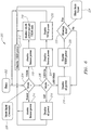
- FIG. 7 illustrates one embodiment of software operation and control of a system with TEDS sensors and/or actuators that include LED indicators for visual information signaling.
- FIG. 7 illustrates the operation of one of the main subsystems.
- Other software routines may be implemented concurrently.
- Fig. 7 shows how software operating on an NCAP may control the use of sensors or actuators including LED indicators.
- step 100 the hardware initializes and powers up. This readies the main board for initialization routines that will sets sensors, actuators, LED indicator visual information or other specific control signals, and reads configuration jumpers.
- Step 102 initializes software routines. This sets up the microcontroller, hardware input/output lines, and software data structures.
- the main loop begins at decision block 104, which checks for hardware interrupts. If there is no hardware interrupt, then decision block 106 checks for data transfer requests. If there are no data transfer requests, then block 121 determines whether there is an LED change request. If there is not an LED change request then decision block 108 determines the need for sensor information. Particularly, block 108 determines if there is a need for acquiring sensor data or servicing due to problem conditions.
- servicing may include checking on the attached sensors etc.; sending a trigger to acknowledge or indicate that the system has run out of consumables, such as in cases of low battery; indicating a self-test failure; indicating calibration fail; or other self-validation messages. If there is no need for servicing, then select software objects are reinitialized at block 110 and the program returns to decision block 104. If the sensor information indicates a request for service, then the sensor service requests are processed at block 112. Once the service requests have been processed, the program proceeds to block 110.
- control is passed to block 123 to manage and control LED and sensor power. Finally, once the indicator (LED) is done being controlled, the process returns to block 104.
- a hardware interrupt is received at decision block 104, then the interrupt is processed at block 114.
- the hardware interrupt can arise from any one of several conditions generated by hardware elements in the unit. If there is no hardware interrupt, then upon completion of reset, the program proceeds to decision block 106. If there is an active data transfer request to send information to or receive information from the NCAP, then block 116 performs handshake and data formatting. Decision block 118 determines the type of data transfer request, either an NCAP read or write.
- the NCAP sends data commands to the sensor.
- the sensor replies by sending the requested information back to the NCAP for interpretation and use.
- the information can be a sensor measured value, TEDS I.D. information, and the like.
- the program then proceeds to decision block 108.
- decision block 122 checks for software trigger requests. If there are software trigger requests, then the trigger requests are processed at block 124. The trigger requests may consist of changing the state of an actuator or reading sensor hardware. If there is no software trigger request, then at block 126 the sensor reads data command sent from the NCAP. As a non-limiting example, this command may be to set an actuator output voltage or update sensor calibration coefficients.
- the software embodiment illustrated in Fig. 7 is just one embodiment for controlling a sensor and it associated indicator.
- control of the indicator is separated in blocks 121 and 123 from other functions related to management of the sensor.
- indicator management and control may be more integrated.
- FIG. 8 is a flow diagram illustrating the operation of one embodiment of client software designed to control a sensor or actuator including an indicator.
- the software may be stored and executed on the user's personal computer.
- the software may be programmed in HTML and/or JAVA.
- the embodiment illustrated in Fig. 8 begins at block 130, which implements a welcome screen at user log-in. Particularly, HTML welcome screens at log-in allow for user configuration information to be sent to the user over the network.
- Block 132 then implements any necessary initialization routines. This may include querying the sensor to download data from the TEDS for unit information and downloading transducer-specific data from the TEDS for each implemented sensor channel and each actuator channel.
- a data display screen is generated at block 134 as per the user configuration file.
- Default settings are used if the user has not updated configuration information. As before, this display screen is sent through the network for display via the user's browser software. Decision block 136 determines if it is necessary to change any settings. This may be implemented by tab selection. If it is not necessary to change any settings, then the program returns to block 134. Thus, the program repeats the steps in a loop consisting of blocks 134 and 136 unless changes are selected or the user logs off.
- a tab selection is made to make changes at decision block 136, then the particular type of tab selection is determined at node 138.
- One possible change is to change the data display. This is implemented at block 140, which is processed at a data display change request. Particularly, the user selects a transducer channel display, display format, and display parameters. As a non-limiting example, this may include graph style, sample frequency, graph axes parameters, and graph axes labels.
- the program validates the user's selections for compatibility with the hardware and the data in the TEDS and the software capabilities. The program then returns to block 134 to display the data screen.
- decision block 142 determines whether the transducer settings to be changed were for TEDS information or for micro-web server default settings or for some other reason such as illuminating the indicator on a particular sensor or actuator. If the transducer settings to be changed were for TEDS information or LED illumination, then the program proceeds to block 144 to change the TEDS settings and/or the indicator settings. If the transducer settings to be changed were for micro-web server default settings, then the program proceeds to block 146 to change the micro-web server settings.
- the user selects the transducer channel to change and the particular parameter to change from a menu list of available TEDS or LED fields indicating current and/or available values. This consists of details of the sensors' parameters and LED functional indication types.
- Decision block 148 reviews the TEDS and LED changes to verify that they are within range and the like. If not, the program returns to block 144. Otherwise, the program advances to block 150 to determine if there are any additional changes. If there are no additional changes, then the program returns to block 134. If there are additional changes, then the program returns to decision block 142.
- block 139 Other types of configuration changes may be handled by block 139.
- other types of configuration changes include but are not limited to data acquisition configuration, logging, status or alarms.
Landscapes
- Physics & Mathematics (AREA)
- General Physics & Mathematics (AREA)
- Business, Economics & Management (AREA)
- Emergency Management (AREA)
- Engineering & Computer Science (AREA)
- Microelectronics & Electronic Packaging (AREA)
- Optics & Photonics (AREA)
- Arrangements For Transmission Of Measured Signals (AREA)
- Transmission And Conversion Of Sensor Element Output (AREA)
- Electromagnetism (AREA)
Applications Claiming Priority (3)
| Application Number | Priority Date | Filing Date | Title |
|---|---|---|---|
| US201361758850P | 2013-01-31 | 2013-01-31 | |
| US201361807018P | 2013-04-01 | 2013-04-01 | |
| PCT/US2014/011438 WO2014120430A1 (en) | 2013-01-31 | 2014-01-14 | Cable with led connection indicator |
Publications (3)
| Publication Number | Publication Date |
|---|---|
| EP2951595A1 EP2951595A1 (en) | 2015-12-09 |
| EP2951595A4 EP2951595A4 (en) | 2016-09-28 |
| EP2951595B1 true EP2951595B1 (en) | 2018-02-21 |
Family
ID=51222298
Family Applications (1)
| Application Number | Title | Priority Date | Filing Date |
|---|---|---|---|
| EP14746890.4A Not-in-force EP2951595B1 (en) | 2013-01-31 | 2014-01-14 | Cable with led connection indicator |
Country Status (5)
| Country | Link |
|---|---|
| US (1) | US9410988B2 (enExample) |
| EP (1) | EP2951595B1 (enExample) |
| JP (1) | JP2016511882A (enExample) |
| CA (1) | CA2899037A1 (enExample) |
| WO (1) | WO2014120430A1 (enExample) |
Families Citing this family (34)
| Publication number | Priority date | Publication date | Assignee | Title |
|---|---|---|---|---|
| US7220239B2 (en) | 2001-12-03 | 2007-05-22 | Ekos Corporation | Catheter with multiple ultrasound radiating members |
| US10182833B2 (en) | 2007-01-08 | 2019-01-22 | Ekos Corporation | Power parameters for ultrasonic catheter |
| ES2471118T3 (es) | 2007-06-22 | 2014-06-25 | Ekos Corporation | Método y aparato para el tratamiento de hemorragias intracraneales |
| US12097357B2 (en) | 2008-09-15 | 2024-09-24 | West Pharma. Services IL, Ltd. | Stabilized pen injector |
| US9393369B2 (en) | 2008-09-15 | 2016-07-19 | Medimop Medical Projects Ltd. | Stabilized pen injector |
| US11458290B2 (en) | 2011-05-11 | 2022-10-04 | Ekos Corporation | Ultrasound system |
| EP2809375B1 (en) | 2012-01-31 | 2021-08-11 | Medimop Medical Projects Ltd. | Time dependent drug delivery apparatus |
| US9463280B2 (en) | 2012-03-26 | 2016-10-11 | Medimop Medical Projects Ltd. | Motion activated septum puncturing drug delivery device |
| US10668213B2 (en) | 2012-03-26 | 2020-06-02 | West Pharma. Services IL, Ltd. | Motion activated mechanisms for a drug delivery device |
| US9889256B2 (en) | 2013-05-03 | 2018-02-13 | Medimop Medical Projects Ltd. | Sensing a status of an infuser based on sensing motor control and power input |
| US10092742B2 (en) * | 2014-09-22 | 2018-10-09 | Ekos Corporation | Catheter system |
| US9744297B2 (en) * | 2015-04-10 | 2017-08-29 | Medimop Medical Projects Ltd. | Needle cannula position as an input to operational control of an injection device |
| CN113181477B (zh) | 2015-06-04 | 2023-07-14 | 麦迪麦珀医疗工程有限公司 | 用于药物释放装置的筒插入 |
| EP3307388B1 (en) | 2015-06-10 | 2022-06-22 | Ekos Corporation | Ultrasound catheter |
| WO2016210360A1 (en) * | 2015-06-24 | 2016-12-29 | Meggitt (Orange County), Inc. | Sensor and cable with local wireless read and write capability and methods of using same |
| US9943270B2 (en) | 2015-06-30 | 2018-04-17 | General Electric Company | Optimization of patient alarm settings for monitoring devices utilizing analytics |
| US9522048B1 (en) | 2015-07-21 | 2016-12-20 | General Electric Company | Physical cable lead identifier for medical systems |
| US9619979B1 (en) | 2016-02-03 | 2017-04-11 | Dell Products, L.P. | Visual indication of cable connection status |
| US11103652B2 (en) | 2016-06-02 | 2021-08-31 | West Pharma. Services IL, Ltd. | Three position needle retraction |
| US10347092B2 (en) * | 2016-07-28 | 2019-07-09 | Banner Engineering Corp. | Omni-directional in-line illumination indicator device |
| US11730892B2 (en) | 2016-08-01 | 2023-08-22 | West Pharma. Services IL, Ltd. | Partial door closure prevention spring |
| US9958622B1 (en) * | 2017-02-03 | 2018-05-01 | Cisco Technology, Inc. | Port and cable connection labeling using optical elements |
| EP3630226B1 (en) | 2017-05-30 | 2025-10-22 | West Pharma. Services Il, Ltd. | Modular drive train for wearable injector |
| EP3450929B1 (en) * | 2017-08-30 | 2020-08-19 | G.R.A.S. Sound & Vibration A/S | System comprising a signal analyzer and sensors with test signal generation |
| CN109521323A (zh) * | 2017-09-18 | 2019-03-26 | 湖南中车时代电动汽车股份有限公司 | 一种接口线路通断状态检测装置及方法 |
| JP7402799B2 (ja) | 2017-12-22 | 2023-12-21 | ウェスト ファーマ サービシーズ イスラエル リミテッド | サイズの異なるカートリッジを利用可能な注射器 |
| FR3076144B1 (fr) * | 2017-12-22 | 2023-04-21 | Bull Sas | Dispositif de surveillance d'une transmission de donnees |
| US11573617B2 (en) * | 2019-01-25 | 2023-02-07 | Dell Products, L.P. | Indicator for AC power adapter |
| TWI691128B (zh) * | 2019-04-23 | 2020-04-11 | 宏正自動科技股份有限公司 | 具有提供辨識資訊功能的電子裝置連接線 |
| US10903608B1 (en) | 2019-08-27 | 2021-01-26 | International Business Machines Corporation | Multi-directional motion monitoring of plugged electrical connector |
| US11705679B2 (en) | 2020-12-18 | 2023-07-18 | Banner Engineering Corp. | In-line modular indicator assembly |
| JP2023127145A (ja) * | 2022-03-01 | 2023-09-13 | 安立計器株式会社 | 測定器の演算装置および探針並びに測定方法 |
| JP7701420B2 (ja) | 2022-10-19 | 2025-07-01 | キストラー ホールディング アクチエンゲゼルシャフト | 圧電測定装置、および測定装置を動作させる方法 |
| US20240242052A1 (en) * | 2023-01-12 | 2024-07-18 | Kistler Holding Ag | Measuring device |
Family Cites Families (19)
| Publication number | Priority date | Publication date | Assignee | Title |
|---|---|---|---|---|
| JPS592079B2 (ja) * | 1975-09-27 | 1984-01-17 | 株式会社山武 | ニセンシキオンドケイソクデンソウカイロ |
| US4070290A (en) | 1976-03-04 | 1978-01-24 | Bird Machine Company, Inc. | Centrifuge with torsional vibration sensing and signaling |
| US4152639A (en) * | 1978-01-27 | 1979-05-01 | Mono-Probe Corporation | Electrical circuit voltage and continuity testing device |
| US4426612A (en) | 1982-04-16 | 1984-01-17 | Baxter Travenol Laboratories, Inc. | Battery charging and testing circuit |
| JPH0724080B2 (ja) * | 1987-04-24 | 1995-03-15 | 株式会社ハ−マン | 遠隔電送装置 |
| US5359290A (en) * | 1993-01-11 | 1994-10-25 | Actron Manufacturing Company | Method and apparatus using a pair of test circuits having LED indicators for testing engine sensors and ignition modules in vehicles |
| US5379643A (en) | 1993-07-21 | 1995-01-10 | Ird Mechanalysis, Inc. | Mount assembly for use with vibration transducers |
| US5650727A (en) * | 1995-04-07 | 1997-07-22 | Wizaed Devices, Inc. | Circuit continuity testing device |
| US5631427A (en) | 1996-01-16 | 1997-05-20 | Dell Usa, L.P. | Accelerometer-based shock/vibration testing apparatus and associated methods for a portable computer |
| US6006164A (en) | 1997-07-22 | 1999-12-21 | Skf Condition Monitoring, Inc. | Portable vibration monitor |
| US5844472A (en) | 1997-07-25 | 1998-12-01 | Lee; Victor Shiu P. | Portable rechargeable power supply adaptor with illuminated key holder |
| US5877618A (en) * | 1997-07-31 | 1999-03-02 | Applied Power, Inc. | Hand held non-contact voltage tester |
| US6459919B1 (en) * | 1997-08-26 | 2002-10-01 | Color Kinetics, Incorporated | Precision illumination methods and systems |
| US20030137310A1 (en) * | 2002-01-22 | 2003-07-24 | Thomas Holzel | Remote viewing screen for test instrument |
| US7532010B2 (en) * | 2006-09-25 | 2009-05-12 | Delphi Technologies, Inc. | Sensing circuit and method for diagnosing open and short circuit conditions of a sensor |
| US7816925B1 (en) * | 2007-06-20 | 2010-10-19 | Gale Robert D | Electrical continuity tester and tracer |
| US8179121B2 (en) | 2009-03-30 | 2012-05-15 | Pcb Piezotronics, Inc. | Bridge sensor with collocated electronics and two-wire interface |
| US9243938B2 (en) | 2010-08-04 | 2016-01-26 | Fluke Corporation | Single TEDS electronic data sheet for multiple accelerometers |
| US8494706B2 (en) * | 2011-08-19 | 2013-07-23 | Federal-Mogul Corporation | Electric fuel pump tester and method |
-
2014
- 2014-01-13 US US14/153,997 patent/US9410988B2/en not_active Expired - Fee Related
- 2014-01-14 CA CA2899037A patent/CA2899037A1/en not_active Abandoned
- 2014-01-14 EP EP14746890.4A patent/EP2951595B1/en not_active Not-in-force
- 2014-01-14 JP JP2015556031A patent/JP2016511882A/ja active Pending
- 2014-01-14 WO PCT/US2014/011438 patent/WO2014120430A1/en not_active Ceased
Non-Patent Citations (1)
| Title |
|---|
| None * |
Also Published As
| Publication number | Publication date |
|---|---|
| EP2951595A1 (en) | 2015-12-09 |
| US20140210631A1 (en) | 2014-07-31 |
| WO2014120430A1 (en) | 2014-08-07 |
| US9410988B2 (en) | 2016-08-09 |
| EP2951595A4 (en) | 2016-09-28 |
| JP2016511882A (ja) | 2016-04-21 |
| CA2899037A1 (en) | 2014-08-07 |
Similar Documents
| Publication | Publication Date | Title |
|---|---|---|
| EP2951595B1 (en) | Cable with led connection indicator | |
| CN101517383B (zh) | 使用磁感应的工业过程装置 | |
| US8838328B2 (en) | Automotive diagnostic system | |
| JP5575986B2 (ja) | プロセス流体温度計測器 | |
| CN105388001B (zh) | 用于阀特征测试的设备和方法 | |
| CN105987715A (zh) | 仪表显示系统 | |
| CN105453141B (zh) | 用于检测电子系统中的故障的设备和方法 | |
| JP6055103B2 (ja) | 端末を改善したフィールド機器 | |
| EP3161361B1 (en) | Methods and systems for adjusting travel sensor alignment on process control valves | |
| JP2018173332A (ja) | 故障診断システム | |
| KR101473694B1 (ko) | 온습도 원격 제어장치와 온습도 원격 제어 시스템 | |
| US20150377945A1 (en) | Diagnostic system for a controller | |
| US20170097249A1 (en) | Sensor and cable with local wireless read and write capability and methods of using same | |
| CN104950213A (zh) | 用于利用dc偏置电流的连接故障自监测的系统、方法和设备 | |
| CN108225615A (zh) | 短路热电偶诊断 | |
| US10612992B2 (en) | Strain gauge detection and orientation system | |
| JP2021025926A (ja) | 振動センサの自己診断方法及び自己診断機能付き振動センサシステム | |
| JP4171260B2 (ja) | マルチドロップ配線故障検知方法およびマルチドロップ配線システム | |
| JP5582673B2 (ja) | 圧力測定装置のパラメータ化方法 | |
| KR101028885B1 (ko) | 계장(계측) 제어장치 | |
| CN110187503B (zh) | 用于查找特定测量仪器的测量仪器识别系统及方法 | |
| JP7351202B2 (ja) | 異常検出装置、電気機器、画像形成装置、電気機器の異常検出方法、及び異常検出プログラム | |
| WO2020061919A1 (zh) | 用于hart控制回路监测的方法、装置、设备、介质及程序 | |
| KR101922510B1 (ko) | 전자기기 및 그 진단방법 | |
| CN117809730A (zh) | 一种ddr dimm故障快速分析设备及方法 |
Legal Events
| Date | Code | Title | Description |
|---|---|---|---|
| PUAI | Public reference made under article 153(3) epc to a published international application that has entered the european phase |
Free format text: ORIGINAL CODE: 0009012 |
|
| 17P | Request for examination filed |
Effective date: 20150807 |
|
| AK | Designated contracting states |
Kind code of ref document: A1 Designated state(s): AL AT BE BG CH CY CZ DE DK EE ES FI FR GB GR HR HU IE IS IT LI LT LU LV MC MK MT NL NO PL PT RO RS SE SI SK SM TR |
|
| AX | Request for extension of the european patent |
Extension state: BA ME |
|
| DAX | Request for extension of the european patent (deleted) | ||
| A4 | Supplementary search report drawn up and despatched |
Effective date: 20160826 |
|
| RIC1 | Information provided on ipc code assigned before grant |
Ipc: G01R 31/28 20060101ALN20160822BHEP Ipc: G01P 15/02 20060101AFI20160822BHEP Ipc: G01R 31/02 20060101ALI20160822BHEP Ipc: G01P 15/09 20060101ALI20160822BHEP Ipc: G01R 13/00 20060101ALN20160822BHEP Ipc: G01D 3/08 20060101ALN20160822BHEP Ipc: G01P 15/08 20060101ALI20160822BHEP |
|
| GRAP | Despatch of communication of intention to grant a patent |
Free format text: ORIGINAL CODE: EPIDOSNIGR1 |
|
| STAA | Information on the status of an ep patent application or granted ep patent |
Free format text: STATUS: GRANT OF PATENT IS INTENDED |
|
| RIC1 | Information provided on ipc code assigned before grant |
Ipc: G01R 31/28 20060101ALN20170928BHEP Ipc: G01P 15/08 20060101ALI20170928BHEP Ipc: G01R 13/00 20060101ALN20170928BHEP Ipc: G01R 31/02 20060101ALI20170928BHEP Ipc: G01L 1/26 20060101ALI20170928BHEP Ipc: G01D 3/08 20060101ALN20170928BHEP Ipc: G01P 15/09 20060101ALI20170928BHEP Ipc: G01L 1/16 20060101ALI20170928BHEP Ipc: G01P 15/02 20130101AFI20170928BHEP |
|
| INTG | Intention to grant announced |
Effective date: 20171031 |
|
| GRAS | Grant fee paid |
Free format text: ORIGINAL CODE: EPIDOSNIGR3 |
|
| GRAA | (expected) grant |
Free format text: ORIGINAL CODE: 0009210 |
|
| STAA | Information on the status of an ep patent application or granted ep patent |
Free format text: STATUS: THE PATENT HAS BEEN GRANTED |
|
| AK | Designated contracting states |
Kind code of ref document: B1 Designated state(s): AL AT BE BG CH CY CZ DE DK EE ES FI FR GB GR HR HU IE IS IT LI LT LU LV MC MK MT NL NO PL PT RO RS SE SI SK SM TR |
|
| REG | Reference to a national code |
Ref country code: GB Ref legal event code: FG4D |
|
| REG | Reference to a national code |
Ref country code: CH Ref legal event code: EP |
|
| REG | Reference to a national code |
Ref country code: AT Ref legal event code: REF Ref document number: 972325 Country of ref document: AT Kind code of ref document: T Effective date: 20180315 |
|
| REG | Reference to a national code |
Ref country code: IE Ref legal event code: FG4D |
|
| REG | Reference to a national code |
Ref country code: DE Ref legal event code: R096 Ref document number: 602014021241 Country of ref document: DE |
|
| REG | Reference to a national code |
Ref country code: NL Ref legal event code: MP Effective date: 20180221 |
|
| REG | Reference to a national code |
Ref country code: LT Ref legal event code: MG4D |
|
| REG | Reference to a national code |
Ref country code: AT Ref legal event code: MK05 Ref document number: 972325 Country of ref document: AT Kind code of ref document: T Effective date: 20180221 |
|
| PG25 | Lapsed in a contracting state [announced via postgrant information from national office to epo] |
Ref country code: HR Free format text: LAPSE BECAUSE OF FAILURE TO SUBMIT A TRANSLATION OF THE DESCRIPTION OR TO PAY THE FEE WITHIN THE PRESCRIBED TIME-LIMIT Effective date: 20180221 Ref country code: LT Free format text: LAPSE BECAUSE OF FAILURE TO SUBMIT A TRANSLATION OF THE DESCRIPTION OR TO PAY THE FEE WITHIN THE PRESCRIBED TIME-LIMIT Effective date: 20180221 Ref country code: CY Free format text: LAPSE BECAUSE OF FAILURE TO SUBMIT A TRANSLATION OF THE DESCRIPTION OR TO PAY THE FEE WITHIN THE PRESCRIBED TIME-LIMIT Effective date: 20180221 Ref country code: NL Free format text: LAPSE BECAUSE OF FAILURE TO SUBMIT A TRANSLATION OF THE DESCRIPTION OR TO PAY THE FEE WITHIN THE PRESCRIBED TIME-LIMIT Effective date: 20180221 Ref country code: NO Free format text: LAPSE BECAUSE OF FAILURE TO SUBMIT A TRANSLATION OF THE DESCRIPTION OR TO PAY THE FEE WITHIN THE PRESCRIBED TIME-LIMIT Effective date: 20180521 Ref country code: ES Free format text: LAPSE BECAUSE OF FAILURE TO SUBMIT A TRANSLATION OF THE DESCRIPTION OR TO PAY THE FEE WITHIN THE PRESCRIBED TIME-LIMIT Effective date: 20180221 Ref country code: FI Free format text: LAPSE BECAUSE OF FAILURE TO SUBMIT A TRANSLATION OF THE DESCRIPTION OR TO PAY THE FEE WITHIN THE PRESCRIBED TIME-LIMIT Effective date: 20180221 |
|
| PG25 | Lapsed in a contracting state [announced via postgrant information from national office to epo] |
Ref country code: SE Free format text: LAPSE BECAUSE OF FAILURE TO SUBMIT A TRANSLATION OF THE DESCRIPTION OR TO PAY THE FEE WITHIN THE PRESCRIBED TIME-LIMIT Effective date: 20180221 Ref country code: AT Free format text: LAPSE BECAUSE OF FAILURE TO SUBMIT A TRANSLATION OF THE DESCRIPTION OR TO PAY THE FEE WITHIN THE PRESCRIBED TIME-LIMIT Effective date: 20180221 Ref country code: LV Free format text: LAPSE BECAUSE OF FAILURE TO SUBMIT A TRANSLATION OF THE DESCRIPTION OR TO PAY THE FEE WITHIN THE PRESCRIBED TIME-LIMIT Effective date: 20180221 Ref country code: RS Free format text: LAPSE BECAUSE OF FAILURE TO SUBMIT A TRANSLATION OF THE DESCRIPTION OR TO PAY THE FEE WITHIN THE PRESCRIBED TIME-LIMIT Effective date: 20180221 Ref country code: GR Free format text: LAPSE BECAUSE OF FAILURE TO SUBMIT A TRANSLATION OF THE DESCRIPTION OR TO PAY THE FEE WITHIN THE PRESCRIBED TIME-LIMIT Effective date: 20180522 Ref country code: BG Free format text: LAPSE BECAUSE OF FAILURE TO SUBMIT A TRANSLATION OF THE DESCRIPTION OR TO PAY THE FEE WITHIN THE PRESCRIBED TIME-LIMIT Effective date: 20180521 |
|
| PG25 | Lapsed in a contracting state [announced via postgrant information from national office to epo] |
Ref country code: AL Free format text: LAPSE BECAUSE OF FAILURE TO SUBMIT A TRANSLATION OF THE DESCRIPTION OR TO PAY THE FEE WITHIN THE PRESCRIBED TIME-LIMIT Effective date: 20180221 Ref country code: EE Free format text: LAPSE BECAUSE OF FAILURE TO SUBMIT A TRANSLATION OF THE DESCRIPTION OR TO PAY THE FEE WITHIN THE PRESCRIBED TIME-LIMIT Effective date: 20180221 Ref country code: PL Free format text: LAPSE BECAUSE OF FAILURE TO SUBMIT A TRANSLATION OF THE DESCRIPTION OR TO PAY THE FEE WITHIN THE PRESCRIBED TIME-LIMIT Effective date: 20180221 Ref country code: RO Free format text: LAPSE BECAUSE OF FAILURE TO SUBMIT A TRANSLATION OF THE DESCRIPTION OR TO PAY THE FEE WITHIN THE PRESCRIBED TIME-LIMIT Effective date: 20180221 |
|
| REG | Reference to a national code |
Ref country code: DE Ref legal event code: R097 Ref document number: 602014021241 Country of ref document: DE |
|
| PG25 | Lapsed in a contracting state [announced via postgrant information from national office to epo] |
Ref country code: SK Free format text: LAPSE BECAUSE OF FAILURE TO SUBMIT A TRANSLATION OF THE DESCRIPTION OR TO PAY THE FEE WITHIN THE PRESCRIBED TIME-LIMIT Effective date: 20180221 Ref country code: SM Free format text: LAPSE BECAUSE OF FAILURE TO SUBMIT A TRANSLATION OF THE DESCRIPTION OR TO PAY THE FEE WITHIN THE PRESCRIBED TIME-LIMIT Effective date: 20180221 Ref country code: CZ Free format text: LAPSE BECAUSE OF FAILURE TO SUBMIT A TRANSLATION OF THE DESCRIPTION OR TO PAY THE FEE WITHIN THE PRESCRIBED TIME-LIMIT Effective date: 20180221 Ref country code: DK Free format text: LAPSE BECAUSE OF FAILURE TO SUBMIT A TRANSLATION OF THE DESCRIPTION OR TO PAY THE FEE WITHIN THE PRESCRIBED TIME-LIMIT Effective date: 20180221 |
|
| PLBE | No opposition filed within time limit |
Free format text: ORIGINAL CODE: 0009261 |
|
| STAA | Information on the status of an ep patent application or granted ep patent |
Free format text: STATUS: NO OPPOSITION FILED WITHIN TIME LIMIT |
|
| 26N | No opposition filed |
Effective date: 20181122 |
|
| PG25 | Lapsed in a contracting state [announced via postgrant information from national office to epo] |
Ref country code: IT Free format text: LAPSE BECAUSE OF FAILURE TO SUBMIT A TRANSLATION OF THE DESCRIPTION OR TO PAY THE FEE WITHIN THE PRESCRIBED TIME-LIMIT Effective date: 20180221 Ref country code: SI Free format text: LAPSE BECAUSE OF FAILURE TO SUBMIT A TRANSLATION OF THE DESCRIPTION OR TO PAY THE FEE WITHIN THE PRESCRIBED TIME-LIMIT Effective date: 20180221 |
|
| REG | Reference to a national code |
Ref country code: DE Ref legal event code: R119 Ref document number: 602014021241 Country of ref document: DE |
|
| PG25 | Lapsed in a contracting state [announced via postgrant information from national office to epo] |
Ref country code: MC Free format text: LAPSE BECAUSE OF FAILURE TO SUBMIT A TRANSLATION OF THE DESCRIPTION OR TO PAY THE FEE WITHIN THE PRESCRIBED TIME-LIMIT Effective date: 20180221 |
|
| REG | Reference to a national code |
Ref country code: CH Ref legal event code: PL |
|
| GBPC | Gb: european patent ceased through non-payment of renewal fee |
Effective date: 20190114 |
|
| PG25 | Lapsed in a contracting state [announced via postgrant information from national office to epo] |
Ref country code: LU Free format text: LAPSE BECAUSE OF NON-PAYMENT OF DUE FEES Effective date: 20190114 |
|
| REG | Reference to a national code |
Ref country code: BE Ref legal event code: MM Effective date: 20190131 |
|
| REG | Reference to a national code |
Ref country code: IE Ref legal event code: MM4A |
|
| PG25 | Lapsed in a contracting state [announced via postgrant information from national office to epo] |
Ref country code: DE Free format text: LAPSE BECAUSE OF NON-PAYMENT OF DUE FEES Effective date: 20190801 Ref country code: FR Free format text: LAPSE BECAUSE OF NON-PAYMENT OF DUE FEES Effective date: 20190131 |
|
| PG25 | Lapsed in a contracting state [announced via postgrant information from national office to epo] |
Ref country code: BE Free format text: LAPSE BECAUSE OF NON-PAYMENT OF DUE FEES Effective date: 20190131 |
|
| PG25 | Lapsed in a contracting state [announced via postgrant information from national office to epo] |
Ref country code: CH Free format text: LAPSE BECAUSE OF NON-PAYMENT OF DUE FEES Effective date: 20190131 Ref country code: LI Free format text: LAPSE BECAUSE OF NON-PAYMENT OF DUE FEES Effective date: 20190131 Ref country code: GB Free format text: LAPSE BECAUSE OF NON-PAYMENT OF DUE FEES Effective date: 20190114 |
|
| PG25 | Lapsed in a contracting state [announced via postgrant information from national office to epo] |
Ref country code: IE Free format text: LAPSE BECAUSE OF NON-PAYMENT OF DUE FEES Effective date: 20190114 |
|
| PG25 | Lapsed in a contracting state [announced via postgrant information from national office to epo] |
Ref country code: TR Free format text: LAPSE BECAUSE OF FAILURE TO SUBMIT A TRANSLATION OF THE DESCRIPTION OR TO PAY THE FEE WITHIN THE PRESCRIBED TIME-LIMIT Effective date: 20180221 |
|
| PG25 | Lapsed in a contracting state [announced via postgrant information from national office to epo] |
Ref country code: MT Free format text: LAPSE BECAUSE OF NON-PAYMENT OF DUE FEES Effective date: 20190114 Ref country code: PT Free format text: LAPSE BECAUSE OF FAILURE TO SUBMIT A TRANSLATION OF THE DESCRIPTION OR TO PAY THE FEE WITHIN THE PRESCRIBED TIME-LIMIT Effective date: 20180621 |
|
| PG25 | Lapsed in a contracting state [announced via postgrant information from national office to epo] |
Ref country code: IS Free format text: LAPSE BECAUSE OF FAILURE TO SUBMIT A TRANSLATION OF THE DESCRIPTION OR TO PAY THE FEE WITHIN THE PRESCRIBED TIME-LIMIT Effective date: 20180621 |
|
| PG25 | Lapsed in a contracting state [announced via postgrant information from national office to epo] |
Ref country code: HU Free format text: LAPSE BECAUSE OF FAILURE TO SUBMIT A TRANSLATION OF THE DESCRIPTION OR TO PAY THE FEE WITHIN THE PRESCRIBED TIME-LIMIT; INVALID AB INITIO Effective date: 20140114 |
|
| PG25 | Lapsed in a contracting state [announced via postgrant information from national office to epo] |
Ref country code: MK Free format text: LAPSE BECAUSE OF FAILURE TO SUBMIT A TRANSLATION OF THE DESCRIPTION OR TO PAY THE FEE WITHIN THE PRESCRIBED TIME-LIMIT Effective date: 20180221 |