EP2950431A1 - Synchronelektromotor - Google Patents
Synchronelektromotor Download PDFInfo
- Publication number
- EP2950431A1 EP2950431A1 EP13872806.8A EP13872806A EP2950431A1 EP 2950431 A1 EP2950431 A1 EP 2950431A1 EP 13872806 A EP13872806 A EP 13872806A EP 2950431 A1 EP2950431 A1 EP 2950431A1
- Authority
- EP
- European Patent Office
- Prior art keywords
- teeth
- phase
- synchronous motor
- stator
- rotor
- Prior art date
- Legal status (The legal status is an assumption and is not a legal conclusion. Google has not performed a legal analysis and makes no representation as to the accuracy of the status listed.)
- Granted
Links
Images

Classifications
-
- H—ELECTRICITY
- H02—GENERATION; CONVERSION OR DISTRIBUTION OF ELECTRIC POWER
- H02K—DYNAMO-ELECTRIC MACHINES
- H02K1/00—Details of the magnetic circuit
- H02K1/06—Details of the magnetic circuit characterised by the shape, form or construction
- H02K1/12—Stationary parts of the magnetic circuit
- H02K1/14—Stator cores with salient poles
- H02K1/146—Stator cores with salient poles consisting of a generally annular yoke with salient poles
-
- H—ELECTRICITY
- H02—GENERATION; CONVERSION OR DISTRIBUTION OF ELECTRIC POWER
- H02K—DYNAMO-ELECTRIC MACHINES
- H02K21/00—Synchronous motors having permanent magnets; Synchronous generators having permanent magnets
- H02K21/12—Synchronous motors having permanent magnets; Synchronous generators having permanent magnets with stationary armatures and rotating magnets
- H02K21/14—Synchronous motors having permanent magnets; Synchronous generators having permanent magnets with stationary armatures and rotating magnets with magnets rotating within the armatures
- H02K21/16—Synchronous motors having permanent magnets; Synchronous generators having permanent magnets with stationary armatures and rotating magnets with magnets rotating within the armatures having annular armature cores with salient poles
-
- H—ELECTRICITY
- H02—GENERATION; CONVERSION OR DISTRIBUTION OF ELECTRIC POWER
- H02K—DYNAMO-ELECTRIC MACHINES
- H02K3/00—Details of windings
- H02K3/04—Windings characterised by the conductor shape, form or construction, e.g. with bar conductors
- H02K3/28—Layout of windings or of connections between windings
-
- H—ELECTRICITY
- H02—GENERATION; CONVERSION OR DISTRIBUTION OF ELECTRIC POWER
- H02K—DYNAMO-ELECTRIC MACHINES
- H02K2213/00—Specific aspects, not otherwise provided for and not covered by codes H02K2201/00 - H02K2211/00
- H02K2213/03—Machines characterised by numerical values, ranges, mathematical expressions or similar information
Definitions
- the present invention relates to a synchronous motor.
- the present invention has been achieved in view of the above problems, and an object of the present invention is to provide a synchronous motor that can achieve high output and high efficiency and can realize high performance in a 10-pole 9-slot synchronous motor.
- a synchronous motor including: a stator in which nine teeth are formed on an annular iron core centering on a shaft center at an equiangular interval in a circumferential direction, the teeth extending toward the shaft center; and a rotor in which pole-oriented permanent magnets having 10 poles are provided on an outer periphery centering on the shaft center at an equiangular interval in a circumferential direction, with magnetic poles with different polarities being alternately provided, the rotor being arranged to face the stator, wherein the teeth are grouped into three phases, with each phase including three adjacent teeth, stator windings are wound continuously in a concentrated manner around the teeth for one phase, with winding directions of the stator windings of each phase being opposite to each other between adjacent teeth as viewed from the shaft center, and a width of a tip portion of a central tooth, which face the rotor, among the teeth of each phase is larger than 32° and smaller
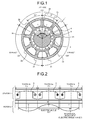
- FIG. 1 is a transverse cross-sectional view of a synchronous motor according to an embodiment. As illustrated in FIG. 1 , in the present embodiment, an explanation will be given of an example of a synchronous motor that uses a rotor 4, in which permanent magnets are positioned to face the inner periphery of a stator 1.
- stator 1 nine projecting iron cores (hereinafter, "teeth") 2a, 2b, and 2c are formed on the annular iron core centering on the shaft center at equiangular intervals (a mechanical angle of 40°) in the circumferential direction, extending toward the shaft center.
- the teeth 2a, 2b, and 2c are grouped into three phases (a U phase, a V phase, a W phase), with each phase including three adjacent teeth.
- the width of the portion of each of the teeth 2a, 2b, and 2c facing the rotor 4 is hereinafter referred to as a "tip width".
- permanent magnets 6 having 10-poles are provided on the outer periphery of a columnar back yoke 5 centering on the shaft center, at equiangular intervals (a mechanical angle of 36°) in the circumferential direction, with magnetic poles with different polarities being alternately provided.
- the rotor 4 is provided rotatably on the inner side of the teeth 2a, 2b, and 2c such that it faces the stator 1.
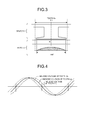
- FIG. 2 is a diagram illustrating a positional relation between teeth for one phase and magnetic poles of the synchronous motor according to the embodiment.
- Stator windings 3 of each of the phases are wound continuously in a concentrated manner around the respective teeth 2a, 2b, and 2c for one phase, with the winding directions of the stator windings 3 wound around the adjacent teeth of each phase being opposite to each other as viewed from the shaft center.
- ⁇ d 20° (a mechanical angle of 4°)
- the tip width of the tooth 2a positioned at the center for each phase is ⁇ 1 and the tip width of the teeth 2b and 2c positioned at both ends of each phase is ⁇ 2.
- FIG. 3 is a diagram illustrating an example in which the center of a tooth and the center of a magnetic pole match each other.
- FIG. 4 is a diagram illustrating the induced voltages of the stator windings wound around the teeth for one phase.
- winding factor Kw As an index indicating how effectively the magnetic flux generated by permanent magnets of a rotor interlinks stator windings, there is a factor generally referred to as a "winding factor Kw".
- the winding factor Kw is a product of a short-pitch winding factor Kp and a distributed winding factor Kd.
- the short-pitch winding factor Kp is calculated on the basis of the width of a magnetic pole of a rotor and the tip width of a tooth of a stator.
- the short-pitch winding factor Kp is a factor that indicates how much magnetic flux passes through the teeth around which stator windings are wound, assuming that the magnetic flux is generated sinusoidally from one magnetic pole of the rotor.
- the short-pitch winding factor Kp is calculated on the basis of the width (an angle) of one magnetic pole of the rotor and the tip width (an angle) of a tooth by using the following equation (1).
- the short-pitch winding factor Kp becomes 1, which is the maximum value.
- the tip width of the tooth is large, a part of the magnetic flux passing through the tooth does not interlink the stator winding and passes through the tip portion of the tooth, and is shunted to an adjacent magnetic pole. Therefore, the short-pitch winding factor Kp decreases.
- the tip width of the tooth is smaller than the width of the magnetic pole, not all the magnetic flux generated from the magnetic pole can interlink the stator winding. Therefore, the short-pitch winding factor Kp decreases.
- the distributed winding factor Kd is used for correcting the state where the amplitude of the induced voltage does not simply become the sum of the induced voltages of the respective stator windings, and the distributed winding factor Kd is generally calculated by using the following equation (2).
- the ratio between the number of poles and the number of slots is a combination such as 2:3 or 4:3, which is generally used in a synchronous motor, even if the number of poles and the number of slots are increased, in the positional relation between the stator windings and the magnetic poles of each phase, only the number of repetitions of the same arrangement increases and the phases of the induced voltages generated in the respective stator windings constituting each phase are not shifted from each other. Therefore, the distributed winding factor Kd becomes 1.
- the distributed winding factor Kd obtained according to the above equation (2) is a factor that is calculated while assuming a case where stator teeth are provided at regular intervals and the tip widths of all the teeth are the same. Therefore, if the teeth are not placed at regular intervals or there is a tooth having a different tip width, the winding factor Kw cannot be calculated by using the above equation (2).
- each magnetic pole of the rotor 4 moves from right to left, in the induced voltages respectively generated in the stator windings wound around the teeth 2a, 2b, and 2c, as illustrated in FIG. 4 , each of the phases of the induced voltages generated in the windings wound around the teeth 2b and 2c at both ends of each phase is shifted by the electric angle of 40° with respect to the induced voltage generated in the stator winding 3 wound around the central tooth 2a of each phase.
- the sum of the induced voltages generated in the stator windings 3 wound around the respective teeth 2a, 2b, and 2c becomes smaller than the value obtained by multiplying the induced voltage generated in the central tooth 2a by three because of the influence of the shift of the phases of the induced voltages generated in the stator windings 3 wound around the respective teeth 2a, 2b, and 2c.
- the distributed winding factor Kd of each of the teeth 2a, 2b, and 2c corresponding to the above equation (2) is assumed, as a factor indicating the influence of a decrease of the induced voltage for each phase due to the shift of the phases of the induced voltages generated in the stator windings 3 wound around the respective teeth 2b and 2c at both ends of each phase, with respect to the induced voltage generated in the stator winding 3 wound around the central tooth 2a of each phase, the distributed winding factor Kd can be calculated by using the following equation (3).
- Kd cos ⁇ ⁇ ⁇ d / 180 ⁇ °
- ⁇ d denotes a phase difference between the phases of the induced voltages generated in the stator windings 3 wound around the teeth 2b and 2c at both ends of each phase and the phase of the induced voltage generated in the stator winding 3 wound around the central tooth 2a of each phase.
- the winding factor Kw of the 10-pole 9-slot synchronous motor according to the embodiment is obtained as described below.
- a winding factor Kw1 of the stator winding 3 wound around the central tooth 2a of each phase is as described below according to the equation (1) and the equation (3), where it is assumed that the short-pitch winding factor is Kp1 and the distributed winding factor is Kd1.
- a winding factor Kw2 of the stator windings 3 wound around the respective teeth 2b and 2c at both ends of each phase is as described below according to the equation (1) and the equation (3), where it is assumed that the short-pitch winding factor is Kp2 and the distributed winding factor is Kd2.
- FIG. 5 is a diagram illustrating the results of calculation for obtaining the short-pitch winding factor Kp, the distributed winding factor Kd, and the winding factor Kw, using the tip widths ⁇ 1 and ⁇ 2 of the teeth of each phase as parameters.
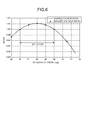
- FIG. 6 is a diagram illustrating the winding factor ratio and the induced voltage ratio with reference to a case where the tip width ⁇ 1 of the central tooth of each phase is 40°.
- the solid line illustrated in FIG. 6 indicates the winding factor ratio with reference to the winding factor Kw when the winding factor Kw is obtained by using the above equation (4) and the tip width ⁇ 1 of the central tooth of each phase is 40°.
- the calculation result of the winding factor Kw in this case becomes 0.9452 as illustrated in FIG. 5 .
- the winding factor Kw gradually increases as the tip width ⁇ 1 of the central tooth of each phase decreases from 40° and becomes the largest when the tip width ⁇ 1 of the central tooth of each phase is 36° ( ⁇ 2 is 42°), which is 0.9553 as illustrated in FIG. 5 .
- the winding factor Kw gradually decreases as the tip width ⁇ 1 of the central tooth of each phase decreases from the tip width ⁇ 1 (36°) of the central tooth of each phase with which the winding factor Kw becomes the largest.
- the tip width ⁇ 1 of the central tooth of each phase is 32° ( ⁇ 2 is 44°)
- the winding factor Kw becomes equal to the calculation result of the winding factor Kw obtained when the tip widths ⁇ 1 and ⁇ 2 of the teeth of each phase are equal to each other, i.e., 40°, which is 0.9452 as illustrated in FIG. 5 .
- the winding factor Kw becomes larger than that of the general 10-pole 9-slot synchronous motor in which the teeth are provided at equiangular intervals and the tip widths ⁇ 1 and ⁇ 2 of the teeth of each phase are equal to each other.
- the winding factor ratio obtained according to the above equation (4) approximately matches the induced voltage ratio obtained by the magnetic field analysis, as illustrated in FIG. 6 .
- the tip width ⁇ 1 of the central tooth of each phase is 36°, the induced voltage increases by up to about 1%.
- the synchronous motor is configured such that the tip width ⁇ 1 of the central tooth 2a of each phase among the teeth 2a, 2b, and 2c of each phase satisfies 32° ⁇ 1 ⁇ 40°. Accordingly, an induced voltage larger than that of the general 10-pole 9-slot synchronous motor can be acquired. Therefore, when a current equivalent to that of the general 10-pole 9-slot synchronous motor is carried, higher torque can be acquired and thus high output can be achieved.
- torque equivalent to that of the general 10-pole 9-slot synchronous motor can be acquired by carrying a current less than that of the general 10-pole 9-slot synchronous motor; therefore, high efficiency can be achieved.
- the tip width ⁇ 1 of the central tooth 2a of each phase among the teeth 2a, 2b, and 2c of each phase is approximately 36°, it is possible to acquire an induced voltage larger than that of the general 10-pole 9-slot synchronous motor by up to about 1%. Consequently, higher output and higher efficiency can be achieved.
- the winding factor Kw1 of the stator winding wound around the central tooth of each phase indicates a higher value than the winding factor Kw2 of the stator windings wound around the teeth at both ends of each phase. If the widths of the portions of the respective teeth around which the stator windings are wound are made non-uniform in accordance with the tip widths of the respective teeth and if the portions of the teeth at both ends of each phase around which the stator windings are wound are brought closer to the central tooth of each phase, the sectional area of the slot between the central tooth of each phase and the teeth at both ends of each phase decreases and the amount of the stator winding that can be accommodated in the slot decreases.
- the performance of the synchronous motor cannot be sufficiently achieved. Further, even if the sectional area of the slot between the respective phases increases, only a space that does not accommodate therein the winding increases, and the sectional area of the stator 1 cannot be effectively utilized. In addition, if the number of windings of the stator winding wound around the central tooth of each phase having a high winding factor Kw1 is reduced, a decrease of the induced voltage increases, which is not effective.
- the teeth 2a, 2b, and 2c are provided at equiangular intervals and the tip widths of the teeth 2b and 2c at both ends of each phase are set to be the same ⁇ 2. Accordingly, harmonic components, which serve as distortions included in the induced voltages generated in the stator windings wound around the respective teeth, cancel out each other, and as a result, low distortion of the induced voltage can be achieved.
- the synchronous motor of the embodiment in the 10-pole 9-slot synchronous motor, by configuring the synchronous motor such that the tip width ⁇ 1 of the central tooth of each phase among the teeth of each phase grouped into three phases, with each phase including three adjacent teeth, satisfies 32° ⁇ 1 ⁇ 40°, an induced voltage larger than that of the general 10-pole 9-slot synchronous motor can be acquired. Therefore, when a current equivalent to that of the general 10-pole 9-slot synchronous motor is carried, higher torque can be acquired and thus high output can be achieved.
- torque equivalent to that of the general 10-pole 9-slot synchronous motor can be acquired by carrying a current less than that of the general 10-pole 9-slot synchronous motor; therefore, high efficiency can be achieved.
- the tip width ⁇ 1 of the central tooth of each phase among the teeth of each phase is approximately 36°, it is possible to acquire an induced voltage larger than that of the general 10-pole 9-slot synchronous motor by up to about 1%. Consequently, higher output and higher efficiency can be achieved.
- the synchronous motor according to the present invention is useful as a three-phase synchronous motor using permanent magnets and is particularly suitable as a 10-pole 9-slot synchronous motor.
- stator 1 stator, 2a, 2b, 2c teeth, 3 stator winding, 4 rotor, 5 back yoke, 6 permanent magnet.
Landscapes
- Engineering & Computer Science (AREA)
- Power Engineering (AREA)
- Iron Core Of Rotating Electric Machines (AREA)
- Permanent Magnet Type Synchronous Machine (AREA)
Applications Claiming Priority (1)
| Application Number | Priority Date | Filing Date | Title |
|---|---|---|---|
| PCT/JP2013/051421 WO2014115278A1 (ja) | 2013-01-24 | 2013-01-24 | 同期電動機 |
Publications (3)
| Publication Number | Publication Date |
|---|---|
| EP2950431A1 true EP2950431A1 (de) | 2015-12-02 |
| EP2950431A4 EP2950431A4 (de) | 2016-12-14 |
| EP2950431B1 EP2950431B1 (de) | 2018-09-12 |
Family
ID=51227094
Family Applications (1)
| Application Number | Title | Priority Date | Filing Date |
|---|---|---|---|
| EP13872806.8A Not-in-force EP2950431B1 (de) | 2013-01-24 | 2013-01-24 | Synchronelektromotor |
Country Status (5)
| Country | Link |
|---|---|
| US (1) | US9800099B2 (de) |
| EP (1) | EP2950431B1 (de) |
| JP (1) | JP6049765B2 (de) |
| CN (1) | CN104885345B (de) |
| WO (1) | WO2014115278A1 (de) |
Families Citing this family (4)
| Publication number | Priority date | Publication date | Assignee | Title |
|---|---|---|---|---|
| US9923493B2 (en) * | 2014-01-09 | 2018-03-20 | Mitsubishi Electric Corporation | Drive circuit for synchronous motor, synchronous motor driven by drive circuit, air blower including synchronous motor, air conditioner including air blower, and method of driving synchronous motor |
| CN106663970A (zh) * | 2014-08-01 | 2017-05-10 | 比亚乔及C.股份公司 | 永磁电动机和发电机以及机车中包括该永磁电动机和发电机的混合马达 |
| US10432040B2 (en) * | 2015-06-17 | 2019-10-01 | Mitsubishi Electric Corporation | Permanent magnet synchronous motor |
| JP7406739B2 (ja) * | 2019-10-25 | 2023-12-28 | 政行 梨木 | モータとその制御装置 |
Family Cites Families (15)
| Publication number | Priority date | Publication date | Assignee | Title |
|---|---|---|---|---|
| JPH088764B2 (ja) | 1985-11-08 | 1996-01-29 | 株式会社日立製作所 | 永久磁石界磁形ブラシレスモ−タ |
| JPS63144749A (ja) * | 1986-12-05 | 1988-06-16 | Nippon Fueroo Furuideikusu Kk | モ−タ |
| JPH0284043A (ja) | 1989-07-13 | 1990-03-26 | Nippon Ferrofluidics Kk | モータ |
| JP3201422B2 (ja) | 1992-01-22 | 2001-08-20 | 日本電産株式会社 | スピンドルモータのヨークに対する磁石の固着構造 |
| US5396134A (en) | 1992-01-22 | 1995-03-07 | Nagano Nidec Corporation | Spindle motor |
| JP2743918B2 (ja) | 1996-12-27 | 1998-04-28 | 株式会社日立製作所 | 永久磁石界磁形ブラシレスモータ |
| JP3604577B2 (ja) | 1999-02-26 | 2004-12-22 | 三菱電機株式会社 | 直流モータ |
| JP4399943B2 (ja) * | 2000-02-29 | 2010-01-20 | 株式会社富士通ゼネラル | 永久磁石電動機 |
| AU2003236179A1 (en) | 2002-03-29 | 2003-10-13 | Matsushita Electric Industrial Co., Ltd. | Motor |
| US6909216B2 (en) | 2002-05-29 | 2005-06-21 | Matsushita Electric Industrial Co., Ltd. | Motor generator |
| JP2004215483A (ja) | 2002-05-29 | 2004-07-29 | Matsushita Electric Ind Co Ltd | モータジェネレータ |
| JP4468740B2 (ja) * | 2003-06-13 | 2010-05-26 | パナソニック株式会社 | モータ |
| EP1487089A3 (de) | 2003-06-13 | 2005-04-27 | Matsushita Electronics Corporation | Permanentmagnetmotor |
| JP4586717B2 (ja) | 2004-12-10 | 2010-11-24 | 日本電産株式会社 | モータ |
| JP2007259541A (ja) | 2006-03-22 | 2007-10-04 | Mitsubishi Electric Corp | 永久磁石式電動機 |
-
2013
- 2013-01-24 WO PCT/JP2013/051421 patent/WO2014115278A1/ja not_active Ceased
- 2013-01-24 JP JP2014558363A patent/JP6049765B2/ja not_active Expired - Fee Related
- 2013-01-24 CN CN201380068813.8A patent/CN104885345B/zh not_active Expired - Fee Related
- 2013-01-24 EP EP13872806.8A patent/EP2950431B1/de not_active Not-in-force
- 2013-01-24 US US14/655,766 patent/US9800099B2/en not_active Expired - Fee Related
Also Published As
| Publication number | Publication date |
|---|---|
| EP2950431B1 (de) | 2018-09-12 |
| WO2014115278A1 (ja) | 2014-07-31 |
| CN104885345B (zh) | 2017-08-22 |
| CN104885345A (zh) | 2015-09-02 |
| US20160006301A1 (en) | 2016-01-07 |
| EP2950431A4 (de) | 2016-12-14 |
| JPWO2014115278A1 (ja) | 2017-01-19 |
| US9800099B2 (en) | 2017-10-24 |
| JP6049765B2 (ja) | 2016-12-21 |
Similar Documents
| Publication | Publication Date | Title |
|---|---|---|
| US10199890B2 (en) | Embedded permanent magnet electric motor | |
| JP4269953B2 (ja) | 回転電機 | |
| US8053942B2 (en) | Axial gap motor | |
| US11799337B2 (en) | Rotating electric machine | |
| KR101834967B1 (ko) | 회전 전기기기 및 회전 전기기기의 스테이터 | |
| US10236732B2 (en) | Inductor type rotary motor | |
| JP2015149819A (ja) | モータ | |
| US10432040B2 (en) | Permanent magnet synchronous motor | |
| WO2017171037A1 (ja) | ロータ及びロータの設計方法 | |
| US9800099B2 (en) | Synchronous motor | |
| EP3661034B1 (de) | Elektrische drehmaschine | |
| JP6929379B2 (ja) | 永久磁石式回転電機 | |
| CN110024271B (zh) | 电动机 | |
| US20180041076A1 (en) | Permanent magnet synchronous motor | |
| JP5907813B2 (ja) | ブラシレスモータ | |
| US20190006898A1 (en) | Motor | |
| JP2009118594A (ja) | アキシャルギャップ型モータ | |
| JP5734135B2 (ja) | 電気機械およびその製造方法 | |
| US10897165B2 (en) | Permanent magnet synchronous motor | |
| JP5611094B2 (ja) | 回転電機 | |
| JP2010183655A (ja) | 回転電機 | |
| JP2017169257A (ja) | 同期電動機および同期発電機 | |
| CN110268601B (zh) | 旋转电机的控制装置、旋转电机及旋转电机的控制方法 | |
| JP2014209829A (ja) | ステータ |
Legal Events
| Date | Code | Title | Description |
|---|---|---|---|
| PUAI | Public reference made under article 153(3) epc to a published international application that has entered the european phase |
Free format text: ORIGINAL CODE: 0009012 |
|
| 17P | Request for examination filed |
Effective date: 20150723 |
|
| AK | Designated contracting states |
Kind code of ref document: A1 Designated state(s): AL AT BE BG CH CY CZ DE DK EE ES FI FR GB GR HR HU IE IS IT LI LT LU LV MC MK MT NL NO PL PT RO RS SE SI SK SM TR |
|
| AX | Request for extension of the european patent |
Extension state: BA ME |
|
| DAX | Request for extension of the european patent (deleted) | ||
| A4 | Supplementary search report drawn up and despatched |
Effective date: 20161110 |
|
| RIC1 | Information provided on ipc code assigned before grant |
Ipc: H02K 1/14 20060101ALI20161104BHEP Ipc: H02K 21/16 20060101AFI20161104BHEP |
|
| GRAP | Despatch of communication of intention to grant a patent |
Free format text: ORIGINAL CODE: EPIDOSNIGR1 |
|
| STAA | Information on the status of an ep patent application or granted ep patent |
Free format text: STATUS: GRANT OF PATENT IS INTENDED |
|
| INTG | Intention to grant announced |
Effective date: 20180323 |
|
| GRAS | Grant fee paid |
Free format text: ORIGINAL CODE: EPIDOSNIGR3 |
|
| GRAA | (expected) grant |
Free format text: ORIGINAL CODE: 0009210 |
|
| STAA | Information on the status of an ep patent application or granted ep patent |
Free format text: STATUS: THE PATENT HAS BEEN GRANTED |
|
| AK | Designated contracting states |
Kind code of ref document: B1 Designated state(s): AL AT BE BG CH CY CZ DE DK EE ES FI FR GB GR HR HU IE IS IT LI LT LU LV MC MK MT NL NO PL PT RO RS SE SI SK SM TR |
|
| REG | Reference to a national code |
Ref country code: GB Ref legal event code: FG4D |
|
| REG | Reference to a national code |
Ref country code: CH Ref legal event code: EP |
|
| REG | Reference to a national code |
Ref country code: IE Ref legal event code: FG4D |
|
| REG | Reference to a national code |
Ref country code: DE Ref legal event code: R096 Ref document number: 602013043708 Country of ref document: DE |
|
| REG | Reference to a national code |
Ref country code: AT Ref legal event code: REF Ref document number: 1041749 Country of ref document: AT Kind code of ref document: T Effective date: 20181015 |
|
| REG | Reference to a national code |
Ref country code: NL Ref legal event code: MP Effective date: 20180912 |
|
| REG | Reference to a national code |
Ref country code: LT Ref legal event code: MG4D |
|
| PG25 | Lapsed in a contracting state [announced via postgrant information from national office to epo] |
Ref country code: GR Free format text: LAPSE BECAUSE OF FAILURE TO SUBMIT A TRANSLATION OF THE DESCRIPTION OR TO PAY THE FEE WITHIN THE PRESCRIBED TIME-LIMIT Effective date: 20181213 Ref country code: BG Free format text: LAPSE BECAUSE OF FAILURE TO SUBMIT A TRANSLATION OF THE DESCRIPTION OR TO PAY THE FEE WITHIN THE PRESCRIBED TIME-LIMIT Effective date: 20181212 Ref country code: NO Free format text: LAPSE BECAUSE OF FAILURE TO SUBMIT A TRANSLATION OF THE DESCRIPTION OR TO PAY THE FEE WITHIN THE PRESCRIBED TIME-LIMIT Effective date: 20181212 Ref country code: RS Free format text: LAPSE BECAUSE OF FAILURE TO SUBMIT A TRANSLATION OF THE DESCRIPTION OR TO PAY THE FEE WITHIN THE PRESCRIBED TIME-LIMIT Effective date: 20180912 Ref country code: FI Free format text: LAPSE BECAUSE OF FAILURE TO SUBMIT A TRANSLATION OF THE DESCRIPTION OR TO PAY THE FEE WITHIN THE PRESCRIBED TIME-LIMIT Effective date: 20180912 Ref country code: LT Free format text: LAPSE BECAUSE OF FAILURE TO SUBMIT A TRANSLATION OF THE DESCRIPTION OR TO PAY THE FEE WITHIN THE PRESCRIBED TIME-LIMIT Effective date: 20180912 Ref country code: SE Free format text: LAPSE BECAUSE OF FAILURE TO SUBMIT A TRANSLATION OF THE DESCRIPTION OR TO PAY THE FEE WITHIN THE PRESCRIBED TIME-LIMIT Effective date: 20180912 |
|
| PG25 | Lapsed in a contracting state [announced via postgrant information from national office to epo] |
Ref country code: AL Free format text: LAPSE BECAUSE OF FAILURE TO SUBMIT A TRANSLATION OF THE DESCRIPTION OR TO PAY THE FEE WITHIN THE PRESCRIBED TIME-LIMIT Effective date: 20180912 Ref country code: HR Free format text: LAPSE BECAUSE OF FAILURE TO SUBMIT A TRANSLATION OF THE DESCRIPTION OR TO PAY THE FEE WITHIN THE PRESCRIBED TIME-LIMIT Effective date: 20180912 Ref country code: LV Free format text: LAPSE BECAUSE OF FAILURE TO SUBMIT A TRANSLATION OF THE DESCRIPTION OR TO PAY THE FEE WITHIN THE PRESCRIBED TIME-LIMIT Effective date: 20180912 |
|
| REG | Reference to a national code |
Ref country code: AT Ref legal event code: MK05 Ref document number: 1041749 Country of ref document: AT Kind code of ref document: T Effective date: 20180912 |
|
| PG25 | Lapsed in a contracting state [announced via postgrant information from national office to epo] |
Ref country code: AT Free format text: LAPSE BECAUSE OF FAILURE TO SUBMIT A TRANSLATION OF THE DESCRIPTION OR TO PAY THE FEE WITHIN THE PRESCRIBED TIME-LIMIT Effective date: 20180912 Ref country code: NL Free format text: LAPSE BECAUSE OF FAILURE TO SUBMIT A TRANSLATION OF THE DESCRIPTION OR TO PAY THE FEE WITHIN THE PRESCRIBED TIME-LIMIT Effective date: 20180912 Ref country code: IS Free format text: LAPSE BECAUSE OF FAILURE TO SUBMIT A TRANSLATION OF THE DESCRIPTION OR TO PAY THE FEE WITHIN THE PRESCRIBED TIME-LIMIT Effective date: 20190112 Ref country code: PL Free format text: LAPSE BECAUSE OF FAILURE TO SUBMIT A TRANSLATION OF THE DESCRIPTION OR TO PAY THE FEE WITHIN THE PRESCRIBED TIME-LIMIT Effective date: 20180912 Ref country code: ES Free format text: LAPSE BECAUSE OF FAILURE TO SUBMIT A TRANSLATION OF THE DESCRIPTION OR TO PAY THE FEE WITHIN THE PRESCRIBED TIME-LIMIT Effective date: 20180912 Ref country code: RO Free format text: LAPSE BECAUSE OF FAILURE TO SUBMIT A TRANSLATION OF THE DESCRIPTION OR TO PAY THE FEE WITHIN THE PRESCRIBED TIME-LIMIT Effective date: 20180912 Ref country code: IT Free format text: LAPSE BECAUSE OF FAILURE TO SUBMIT A TRANSLATION OF THE DESCRIPTION OR TO PAY THE FEE WITHIN THE PRESCRIBED TIME-LIMIT Effective date: 20180912 Ref country code: CZ Free format text: LAPSE BECAUSE OF FAILURE TO SUBMIT A TRANSLATION OF THE DESCRIPTION OR TO PAY THE FEE WITHIN THE PRESCRIBED TIME-LIMIT Effective date: 20180912 Ref country code: EE Free format text: LAPSE BECAUSE OF FAILURE TO SUBMIT A TRANSLATION OF THE DESCRIPTION OR TO PAY THE FEE WITHIN THE PRESCRIBED TIME-LIMIT Effective date: 20180912 |
|
| PG25 | Lapsed in a contracting state [announced via postgrant information from national office to epo] |
Ref country code: PT Free format text: LAPSE BECAUSE OF FAILURE TO SUBMIT A TRANSLATION OF THE DESCRIPTION OR TO PAY THE FEE WITHIN THE PRESCRIBED TIME-LIMIT Effective date: 20190112 Ref country code: SM Free format text: LAPSE BECAUSE OF FAILURE TO SUBMIT A TRANSLATION OF THE DESCRIPTION OR TO PAY THE FEE WITHIN THE PRESCRIBED TIME-LIMIT Effective date: 20180912 Ref country code: SK Free format text: LAPSE BECAUSE OF FAILURE TO SUBMIT A TRANSLATION OF THE DESCRIPTION OR TO PAY THE FEE WITHIN THE PRESCRIBED TIME-LIMIT Effective date: 20180912 |
|
| REG | Reference to a national code |
Ref country code: DE Ref legal event code: R097 Ref document number: 602013043708 Country of ref document: DE |
|
| PLBE | No opposition filed within time limit |
Free format text: ORIGINAL CODE: 0009261 |
|
| STAA | Information on the status of an ep patent application or granted ep patent |
Free format text: STATUS: NO OPPOSITION FILED WITHIN TIME LIMIT |
|
| PG25 | Lapsed in a contracting state [announced via postgrant information from national office to epo] |
Ref country code: DK Free format text: LAPSE BECAUSE OF FAILURE TO SUBMIT A TRANSLATION OF THE DESCRIPTION OR TO PAY THE FEE WITHIN THE PRESCRIBED TIME-LIMIT Effective date: 20180912 |
|
| 26N | No opposition filed |
Effective date: 20190613 |
|
| PG25 | Lapsed in a contracting state [announced via postgrant information from national office to epo] |
Ref country code: SI Free format text: LAPSE BECAUSE OF FAILURE TO SUBMIT A TRANSLATION OF THE DESCRIPTION OR TO PAY THE FEE WITHIN THE PRESCRIBED TIME-LIMIT Effective date: 20180912 Ref country code: MC Free format text: LAPSE BECAUSE OF FAILURE TO SUBMIT A TRANSLATION OF THE DESCRIPTION OR TO PAY THE FEE WITHIN THE PRESCRIBED TIME-LIMIT Effective date: 20180912 |
|
| REG | Reference to a national code |
Ref country code: CH Ref legal event code: PL |
|
| PG25 | Lapsed in a contracting state [announced via postgrant information from national office to epo] |
Ref country code: LU Free format text: LAPSE BECAUSE OF NON-PAYMENT OF DUE FEES Effective date: 20190124 |
|
| REG | Reference to a national code |
Ref country code: BE Ref legal event code: MM Effective date: 20190131 |
|
| REG | Reference to a national code |
Ref country code: IE Ref legal event code: MM4A |
|
| PG25 | Lapsed in a contracting state [announced via postgrant information from national office to epo] |
Ref country code: BE Free format text: LAPSE BECAUSE OF NON-PAYMENT OF DUE FEES Effective date: 20190131 |
|
| PG25 | Lapsed in a contracting state [announced via postgrant information from national office to epo] |
Ref country code: LI Free format text: LAPSE BECAUSE OF NON-PAYMENT OF DUE FEES Effective date: 20190131 Ref country code: CH Free format text: LAPSE BECAUSE OF NON-PAYMENT OF DUE FEES Effective date: 20190131 |
|
| PG25 | Lapsed in a contracting state [announced via postgrant information from national office to epo] |
Ref country code: IE Free format text: LAPSE BECAUSE OF NON-PAYMENT OF DUE FEES Effective date: 20190124 |
|
| PG25 | Lapsed in a contracting state [announced via postgrant information from national office to epo] |
Ref country code: TR Free format text: LAPSE BECAUSE OF FAILURE TO SUBMIT A TRANSLATION OF THE DESCRIPTION OR TO PAY THE FEE WITHIN THE PRESCRIBED TIME-LIMIT Effective date: 20180912 |
|
| PG25 | Lapsed in a contracting state [announced via postgrant information from national office to epo] |
Ref country code: MT Free format text: LAPSE BECAUSE OF NON-PAYMENT OF DUE FEES Effective date: 20190124 |
|
| PG25 | Lapsed in a contracting state [announced via postgrant information from national office to epo] |
Ref country code: CY Free format text: LAPSE BECAUSE OF FAILURE TO SUBMIT A TRANSLATION OF THE DESCRIPTION OR TO PAY THE FEE WITHIN THE PRESCRIBED TIME-LIMIT Effective date: 20180912 |
|
| PG25 | Lapsed in a contracting state [announced via postgrant information from national office to epo] |
Ref country code: HU Free format text: LAPSE BECAUSE OF FAILURE TO SUBMIT A TRANSLATION OF THE DESCRIPTION OR TO PAY THE FEE WITHIN THE PRESCRIBED TIME-LIMIT; INVALID AB INITIO Effective date: 20130124 |
|
| PG25 | Lapsed in a contracting state [announced via postgrant information from national office to epo] |
Ref country code: MK Free format text: LAPSE BECAUSE OF FAILURE TO SUBMIT A TRANSLATION OF THE DESCRIPTION OR TO PAY THE FEE WITHIN THE PRESCRIBED TIME-LIMIT Effective date: 20180912 |
|
| P01 | Opt-out of the competence of the unified patent court (upc) registered |
Effective date: 20230512 |
|
| REG | Reference to a national code |
Ref country code: DE Ref legal event code: R084 Ref document number: 602013043708 Country of ref document: DE |
|
| PGFP | Annual fee paid to national office [announced via postgrant information from national office to epo] |
Ref country code: GB Payment date: 20231130 Year of fee payment: 12 |
|
| PGFP | Annual fee paid to national office [announced via postgrant information from national office to epo] |
Ref country code: FR Payment date: 20231212 Year of fee payment: 12 |
|
| REG | Reference to a national code |
Ref country code: GB Ref legal event code: 746 Effective date: 20240320 |
|
| PGFP | Annual fee paid to national office [announced via postgrant information from national office to epo] |
Ref country code: DE Payment date: 20231128 Year of fee payment: 12 |
|
| REG | Reference to a national code |
Ref country code: DE Ref legal event code: R119 Ref document number: 602013043708 Country of ref document: DE |
|
| GBPC | Gb: european patent ceased through non-payment of renewal fee |
Effective date: 20250124 |
|
| PG25 | Lapsed in a contracting state [announced via postgrant information from national office to epo] |
Ref country code: DE Free format text: LAPSE BECAUSE OF NON-PAYMENT OF DUE FEES Effective date: 20250801 |
|
| PG25 | Lapsed in a contracting state [announced via postgrant information from national office to epo] |
Ref country code: GB Free format text: LAPSE BECAUSE OF NON-PAYMENT OF DUE FEES Effective date: 20250124 |
|
| PG25 | Lapsed in a contracting state [announced via postgrant information from national office to epo] |
Ref country code: FR Free format text: LAPSE BECAUSE OF NON-PAYMENT OF DUE FEES Effective date: 20250131 |