EP3661034B1 - Elektrische drehmaschine - Google Patents
Elektrische drehmaschine Download PDFInfo
- Publication number
- EP3661034B1 EP3661034B1 EP18837348.4A EP18837348A EP3661034B1 EP 3661034 B1 EP3661034 B1 EP 3661034B1 EP 18837348 A EP18837348 A EP 18837348A EP 3661034 B1 EP3661034 B1 EP 3661034B1
- Authority
- EP
- European Patent Office
- Prior art keywords
- rotor
- speed rotor
- torque
- stator
- low
- Prior art date
- Legal status (The legal status is an assumption and is not a legal conclusion. Google has not performed a legal analysis and makes no representation as to the accuracy of the status listed.)
- Active
Links
Images



Classifications
-
- H—ELECTRICITY
- H02—GENERATION; CONVERSION OR DISTRIBUTION OF ELECTRIC POWER
- H02K—DYNAMO-ELECTRIC MACHINES
- H02K16/00—Machines with more than one rotor or stator
- H02K16/02—Machines with one stator and two or more rotors
-
- H—ELECTRICITY
- H02—GENERATION; CONVERSION OR DISTRIBUTION OF ELECTRIC POWER
- H02K—DYNAMO-ELECTRIC MACHINES
- H02K49/00—Dynamo-electric clutches; Dynamo-electric brakes
- H02K49/10—Dynamo-electric clutches; Dynamo-electric brakes of the permanent-magnet type
- H02K49/102—Magnetic gearings, i.e. assembly of gears, linear or rotary, by which motion is magnetically transferred without physical contact
-
- H—ELECTRICITY
- H02—GENERATION; CONVERSION OR DISTRIBUTION OF ELECTRIC POWER
- H02K—DYNAMO-ELECTRIC MACHINES
- H02K1/00—Details of the magnetic circuit
- H02K1/06—Details of the magnetic circuit characterised by the shape, form or construction
- H02K1/12—Stationary parts of the magnetic circuit
- H02K1/16—Stator cores with slots for windings
-
- H—ELECTRICITY
- H02—GENERATION; CONVERSION OR DISTRIBUTION OF ELECTRIC POWER
- H02K—DYNAMO-ELECTRIC MACHINES
- H02K1/00—Details of the magnetic circuit
- H02K1/06—Details of the magnetic circuit characterised by the shape, form or construction
- H02K1/12—Stationary parts of the magnetic circuit
- H02K1/17—Stator cores with permanent magnets
-
- H—ELECTRICITY
- H02—GENERATION; CONVERSION OR DISTRIBUTION OF ELECTRIC POWER
- H02K—DYNAMO-ELECTRIC MACHINES
- H02K1/00—Details of the magnetic circuit
- H02K1/06—Details of the magnetic circuit characterised by the shape, form or construction
- H02K1/22—Rotating parts of the magnetic circuit
- H02K1/27—Rotor cores with permanent magnets
-
- H—ELECTRICITY
- H02—GENERATION; CONVERSION OR DISTRIBUTION OF ELECTRIC POWER
- H02K—DYNAMO-ELECTRIC MACHINES
- H02K15/00—Processes or apparatus specially adapted for manufacturing, assembling, maintaining or repairing of dynamo-electric machines
- H02K15/02—Processes or apparatus specially adapted for manufacturing, assembling, maintaining or repairing of dynamo-electric machines of stator or rotor bodies
- H02K15/03—Processes or apparatus specially adapted for manufacturing, assembling, maintaining or repairing of dynamo-electric machines of stator or rotor bodies having permanent magnets
-
- H—ELECTRICITY
- H02—GENERATION; CONVERSION OR DISTRIBUTION OF ELECTRIC POWER
- H02K—DYNAMO-ELECTRIC MACHINES
- H02K3/00—Details of windings
- H02K3/04—Windings characterised by the conductor shape, form or construction, e.g. with bar conductors
- H02K3/18—Windings for salient poles
-
- H—ELECTRICITY
- H02—GENERATION; CONVERSION OR DISTRIBUTION OF ELECTRIC POWER
- H02K—DYNAMO-ELECTRIC MACHINES
- H02K51/00—Dynamo-electric gears, i.e. dynamo-electric means for transmitting mechanical power from a driving shaft to a driven shaft and comprising structurally interrelated motor and generator parts
-
- H—ELECTRICITY
- H02—GENERATION; CONVERSION OR DISTRIBUTION OF ELECTRIC POWER
- H02K—DYNAMO-ELECTRIC MACHINES
- H02K7/00—Arrangements for handling mechanical energy structurally associated with dynamo-electric machines, e.g. structural association with mechanical driving motors or auxiliary dynamo-electric machines
- H02K7/10—Structural association with clutches, brakes, gears, pulleys or mechanical starters
- H02K7/116—Structural association with clutches, brakes, gears, pulleys or mechanical starters with gears
Definitions
- the present invention relates to a rotary electric machine having a magnetic deceleration mechanism.
- Patent Literature (PTL) 1 and Non-patent Literature (NPL) 1 each disclose a mechanism of a rotary electric machine including a magnetic transmission mechanism.
- Each of the mechanism of the rotary electric machine includes, in stated order from radially centermost to radially outermost, a first rotor including permanent magnets, a second rotor including pole pieces, and a stator including a winding, and the first rotor, the second rotor, and the stator are disposed coaxially and spaced apart from one another.
- the first rotor is driven by applying three-phase current to the winding of the stator, and reaction torque of a magnetic reduction gear is generated in the second rotor by rotation of the first rotor.
- the system achieves a small size or high power by combining the magnetic reduction gear and the rotary electric machine together.
- the system also serves as a torque limiter by magnetically slipping when the torque exceeds allowable torque.
- NPL 1 Noboru NIGUCHI, Katsuhiro HIRATA, "A Novel Magnetic-Geared Motor", Journal of the Japan Society of Applied Electromagnetics and Mechanics, Vol. 21, No. 2 (2013), pp. 110 to 115 Further relevant prior art is EP 3 007 336 A1 .
- torque can be generated in only one of the rotors by rotating magnetic field of the winding of the stator, and the generated torque is reduced and transmitted to the other rotor.
- the present invention aims to achieve a small-sized rotary electric machine to save resources and reduce costs, and also achieve high power to increase the output of such a rotary electric machine in a limited space.
- the present invention makes it possible to achieve a rotary electric machine having a higher power density.
- the effects can be obtained that two rotors generate torque by rotary magnetic field of the windings of the stator, and the torque generated in one of the rotors can be reduced and transmitted to the other rotor.
- These effects are advantageous in, for example, achieving a small-sized rotary electric machine to save resources and reduce costs, and also achieving high power to increase the output of such a rotary electric machine in a limited space.
- the rotary electric machine according to the present invention is useful.
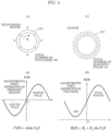
- FIG. 1 and FIG. 2 are diagrams for describing a structure and the deceleration principle of a conventional magnetic deceleration mechanism. First, the deceleration principle is described with reference to these diagrams.
- the conventional magnetic deceleration mechanism includes: high-speed rotor 100 that is disposed in a center portion; stator 200 that is disposed between high-speed rotor 100 and low-speed rotor 300; and low-speed rotor 300 that is disposed on the outermost circumference, all of which are disposed coaxially and spaced apart from one another.
- Each of the components has a predetermined length in an axis direction.
- High-speed rotor 100 is connected to, for example, an output axis of a motor etc. to receive torque which is not illustrated.
- High-speed rotor 100 includes: an iron core made of a magnetic material and having a shape of, for example, a shaft (or may be cylindrical); and pole pairs 102 made up of permanent magnets such that north poles and south poles are disposed alternately and evenly on the outer circumference of the iron core in a circumferential direction.
- the total number of pole pairs is two.
- Stator 200 includes a plurality of pole pieces 201 that are bar shaped, made of a magnetic material and, extended in the axis direction, and disposed on a circumference at a predetermined pitch to face the outer circumference of pole pairs 102.
- Each of pole pieces 201 has a vertical cross-section that is substantially rectangle, and its planar section faces in a radial direction.
- Low-speed rotor 300 includes: annular body 301 made of a magnetic material and a plurality of magnetic poles 302 composed of permanent magnets disposed such that the north poles and the south poles are disposed alternately on the inner circumference of annular body 301 in the circumferential direction.
- N h in the first term is the same component as the total number of pole pairs N h of high-speed rotor 100.
- N S - N h and Ns + N h in the second term are harmonic components.
- magnetic flux ⁇ ( ⁇ ) generated around the outer circumference of the pole pieces of the stator includes two types of harmonic components Ns - N h and Ns + N h , other than basic component (main component) N h .
- N h in the first term of magnetic flux ⁇ ( ⁇ + ⁇ ) is ( ⁇ + ⁇ ), i.e., + ⁇ component is present
- N h is a component rotating at the same speed as high-speed rotor 100.
- Ns - N h and Ns + N h in the second term are both harmonics having different speeds from the speed of high-speed rotor 100.
- Ns - N h rotates by -N h ⁇ /(N S -N h ) with respect to the rotation by ⁇ of high-speed rotor 100.
- N s + N h since the rotation is performed by N h ⁇ / (Ns + N h ) with respect to the rotation by ⁇ of the high-speed rotor, both of the rotation speeds differ from the basic component.
- the total number of magnetic poles of low-speed rotors 300 is set to either Ns - N h or Ns + N h , low-speed rotor 300 will rotate at a different rotation speed with respect to the total number of magnetic poles that is set.
- Ns N l + N h
- a driving source that mechanically rotates the stator is necessary, i.e, typically, adding a motor is necessary, for example.
- new problems will arise, for example, the mechanism will be complicated, increase in size, and expensive.
- windings are provided to the pole pieces of the stator of the conventional magnetic deceleration mechanism illustrated in FIG. 1 .
- the present invention provides a rotary electric machine that is capable of generating torque in two rotors.
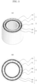
- a rotary electric machine includes, in stated order from outermost to centermost, low-speed rotor 3 that includes magnetic material 31 and permanent magnets 30; stator 2 that includes coils 21 wound around pole pieces 20; and high-speed rotor 1 that includes permanent magnets 11 and magnetic material 10.
- high-speed rotor 1 and low-speed rotor 3 are examples of the first rotor and the second rotor, respectively, and the operating principle works even if high-speed rotor 1 and low-speed rotor 3 are interchanged with each other.
- low-speed rotor 3 that is multipolar is disposed on the outer side.
- coils 21 wound around pole pieces 20 are wound by short-pitch concentrated winding, the winding method is not limited to this method.
- the rotary electric machine includes: a first rotor, stator 2, and a second rotor that are coaxially disposed in stated order from radially centermost to radially outermost and spaced apart from one another, stator 2 including a plurality of pole pieces 20 and a plurality of windings (coils 21) in a circumferential direction.
- the first rotor includes magnetic material 10 and permanent magnets 11.
- the second rotor includes magnetic material 31 and permanent magnets 30.
- the plurality of windings generate electromagnetic torque in the first rotor and the second rotor, the electromagnetic torque is magnetically transferred to the second rotor by rotation of the first rotor, or magnetically transferred to the first rotor by rotation of the second rotor, and in one of the first rotor and the second rotor, torque that is magnetically transferred from an other of the first rotor and the second rotor is superimposed on the electromagnetic torque.
- frequency F H of the back electromotive force generated in coils 21 of stator 2 is N H ⁇ H .
- rotation speed ⁇ L of low-speed rotor 3 is ⁇ H /G r
- the frequency of the back electromotive force generated in coils 21 of stator 2 by rotation of high-speed rotor 1 and the frequency of the back electromotive force generated in coils 21 of stator 2 by rotation of low-speed rotor 3 are the same.
- high-speed rotor 1 and low-speed rotor 3 are included in the rotary electric machine according to the present invention that fulfills the conditions for establishing the magnetic deceleration mechanism.
- high-speed rotor 1 and the total number of pole pieces of stator 2 and low-speed rotor 3 and the total number of pole pieces of stator 2 is a combination that can cause, for example, a three-phase permanent magnet brush-less motor to rotate, torque is generated in both rotors by the current applied to coils 21 of stator 2.
- the high-speed rotor was forcibly rotated at -60 r/min
- the low-speed rotor was forcibly rotated at 30 r/min
- sine-wave current was applied, and the torque of the low-speed rotor when the phases of the high-speed rotor and the low-speed rotor was changed was obtained.
- FIG. 6 Regardless of the phase difference, the torque of the low-speed rotor increased with the increasing electric current.
- the torque of the low-speed rotor was 89 Nm, and the torque increased by 44 Nm compared with the torque when the electric current is not applied.
- the torque of the low-speed rotor when the current is not applied is equivalent to the transmission torque generated due to the phase difference with respect to the high-speed rotor.
- This can be achieved also in a rotary electric machine with a conventional magnetic deceleration mechanism. Since the torque of the low-speed rotor increases with the increasing electric current in the state where the phase difference is constant, the reaction torque received from the high-speed rotor that serves as a magnetic reduction gear is superimposed on the torque generated in the low-speed rotor by the reaction torque generated by magnetomotive force of the coils.
- the initial phase difference is set to 4 degrees, and the operation when the magnetomotive force with an amplitude of 150 A is applied to the coils is verified.
- the high-speed rotor was rotated at 60 r/min, and electric current is inputted according to rotation positions of the high-speed rotor.
- load L 89.5 Nm was applied to the low-speed rotor, and the torque generated in each rotor and the number of rotations of the low-speed rotor were obtained. This result is shown in FIGs. 7 and 8 .
- the average torque of the high-speed rotor was -2.1 Nm and the average torque of the low-speed rotor was 88.8 Nm as shown in FIG. 7 , and the average rotation speed of the low-speed rotor was 29.8 r/min as shown in FIG. 8 .
- the average torque of the high-speed rotor should be theoretically zero, torque ripple and a time period in which averaging processing is performed influence the average torque, and thus the average torque of the high-speed rotor is not zero.
- the ratio of rotation speed between both rotors is approximately equal to the reduction ratio.
- the torque of the low-speed rotor fluctuates around approximately 89 Nm, and has hardly changed since the time zero.
- the present disclosure can be used for rotary electric machines in general that have a magnetic deceleration mechanism.
Landscapes
- Engineering & Computer Science (AREA)
- Power Engineering (AREA)
- Manufacturing & Machinery (AREA)
- Permanent Magnet Type Synchronous Machine (AREA)
- Dynamo-Electric Clutches, Dynamo-Electric Brakes (AREA)
- Permanent Field Magnets Of Synchronous Machinery (AREA)
Claims (2)
- Elektrische Drehmaschine, die umfasst:einen ersten Rotor (1, 100), einen Stator (2) und einen zweiten Rotor (3, 300), die koaxial in der angegebenen Reihenfolge von radial in der Mitte nach radial außen angeordnet und voneinander beabstandet sind, wobei der Stator (2) mehrere Polstücke (20, 201) und mehrere Wicklungen in Umfangsrichtung umfasst; odereinen zweiten Rotor (3, 300), einen Stator (2) und einen ersten Rotor (1, 100), die koaxial in der angegebenen Reihenfolge von radial am weitesten nach radial außen angeordnet und voneinander beabstandet sind, wobei der Stator (2) mehrere Polstücke (20, 201) und mehrere Wicklungen in einer Umfangsrichtung umfasst, wobei der erste Rotor (1, 100) ein Schnelläuferrotor ist,der zweite Rotor (3, 300) ein Langsamläuferrotor ist,der erste Rotor (1, 100) und der zweite Rotor (3, 300) jeweils ein magnetisches Material und Permanentmagnete (11, 30) umfassen,die mehreren Wicklungen ein elektromagnetisches Drehmoment im ersten Rotor (1, 100) und im zweiten Rotor (3, 300) erzeugen,das elektromagnetische Drehmoment durch Drehung des ersten Rotors (1, 100) magnetisch auf den zweiten Rotor (3, 300) übertragen wird,im zweiten Rotor (3, 300) dem elektromagnetischen Drehmoment ein magnetisch vom ersten Rotor (1, 100) übertragenes Drehmoment überlagert wird, undeine Gesamtzahl der magnetischen Polschuhe (20, 201) des Stators (2) 12 beträgt, und eine Gesamtzahl der Polpaare (102) des ersten Rotors (1, 100) 4 beträgt, dadurch gekennzeichnet, dasseine Gesamtzahl von Polpaaren (102) des zweiten Rotors (3, 300) 8 beträgt.
- Elektrische Drehmaschine nach Anspruch 1, wobei
der zweite Rotor (3, 300) beschleunigt oder abgebremst wird, wenn das vom ersten Rotor (1, 100) magnetisch übertragene Drehmoment überlagert wird.
Applications Claiming Priority (2)
| Application Number | Priority Date | Filing Date | Title |
|---|---|---|---|
| JP2017144862 | 2017-07-26 | ||
| PCT/JP2018/027788 WO2019022100A1 (ja) | 2017-07-26 | 2018-07-25 | 回転電機 |
Publications (3)
| Publication Number | Publication Date |
|---|---|
| EP3661034A1 EP3661034A1 (de) | 2020-06-03 |
| EP3661034A4 EP3661034A4 (de) | 2020-07-08 |
| EP3661034B1 true EP3661034B1 (de) | 2024-05-01 |
Family
ID=65040174
Family Applications (1)
| Application Number | Title | Priority Date | Filing Date |
|---|---|---|---|
| EP18837348.4A Active EP3661034B1 (de) | 2017-07-26 | 2018-07-25 | Elektrische drehmaschine |
Country Status (5)
| Country | Link |
|---|---|
| US (1) | US20200161948A1 (de) |
| EP (1) | EP3661034B1 (de) |
| JP (1) | JP7123931B2 (de) |
| CN (1) | CN110651417A (de) |
| WO (1) | WO2019022100A1 (de) |
Families Citing this family (4)
| Publication number | Priority date | Publication date | Assignee | Title |
|---|---|---|---|---|
| EP4270745A4 (de) * | 2020-12-23 | 2024-02-28 | Mitsubishi Electric Corporation | Elektrische drehmaschine mit permanentmagnet |
| JP7661519B2 (ja) * | 2021-10-20 | 2025-04-14 | 三菱重工業株式会社 | 可変速動力装置及び制御方法 |
| FR3130357B1 (fr) * | 2021-12-15 | 2026-03-27 | Ubiblue | Générateur magnétocalorique à efficacité augmentée |
| JP7829446B2 (ja) * | 2022-08-19 | 2026-03-13 | 三菱重工業株式会社 | 可変速動力装置及び制御方法 |
Family Cites Families (16)
| Publication number | Priority date | Publication date | Assignee | Title |
|---|---|---|---|---|
| JPS524094B2 (de) | 1973-01-18 | 1977-02-01 | ||
| AT408045B (de) * | 1998-01-30 | 2001-08-27 | Schroedl Manfred Dipl Ing Dr | Elektrische maschine |
| JP3637837B2 (ja) * | 2000-03-29 | 2005-04-13 | 日産自動車株式会社 | 回転電機の制御装置 |
| NL1020095C2 (nl) * | 2002-03-01 | 2003-09-02 | Tno | Elektromechanische omzetter. |
| GB0810097D0 (en) * | 2008-06-03 | 2008-07-09 | Magnomatics Ltd | Magnetic gear |
| US8847464B2 (en) * | 2008-06-12 | 2014-09-30 | General Electric Company | Electrical machine with improved stator flux pattern across a rotor that permits higher torque density |
| JP5845429B2 (ja) * | 2010-03-08 | 2016-01-20 | パナソニックIpマネジメント株式会社 | モータ |
| JP2012205348A (ja) * | 2011-03-24 | 2012-10-22 | Mitsubishi Electric Corp | 磁気ギア |
| GB201308270D0 (en) * | 2013-05-08 | 2013-06-12 | Magnomatics Ltd | Methods and apparatus for rotor position estimation |
| CN103346655B (zh) * | 2013-07-03 | 2016-01-20 | 浙江大学 | 双转子永磁电机及洗衣机 |
| EP3147542B1 (de) * | 2014-05-20 | 2020-02-12 | IHI Corporation | Magnetwellengetriebevorrichtung |
| EP3007336B1 (de) * | 2014-10-07 | 2016-11-30 | C.R.F. Società Consortile per Azioni | Elektrische Synchronmaschine mit zwei Rotoren |
| JP2016093052A (ja) * | 2014-11-10 | 2016-05-23 | 株式会社デンソー | 回転電機 |
| JP2016168108A (ja) * | 2015-03-11 | 2016-09-23 | パナソニック株式会社 | モータ装置及び該モータ装置を備える洗濯機 |
| JP6820090B2 (ja) * | 2015-07-21 | 2021-01-27 | 三星電子株式会社Samsung Electronics Co.,Ltd. | 洗濯機、および、そのモータ |
| CN106899194A (zh) * | 2017-03-31 | 2017-06-27 | 东南大学 | 基于磁通调制复合电机的海流能一体化发电装置 |
-
2018
- 2018-07-25 JP JP2019532657A patent/JP7123931B2/ja active Active
- 2018-07-25 WO PCT/JP2018/027788 patent/WO2019022100A1/ja not_active Ceased
- 2018-07-25 EP EP18837348.4A patent/EP3661034B1/de active Active
- 2018-07-25 CN CN201880033211.1A patent/CN110651417A/zh active Pending
- 2018-07-25 US US16/615,379 patent/US20200161948A1/en not_active Abandoned
Also Published As
| Publication number | Publication date |
|---|---|
| CN110651417A (zh) | 2020-01-03 |
| EP3661034A1 (de) | 2020-06-03 |
| EP3661034A4 (de) | 2020-07-08 |
| US20200161948A1 (en) | 2020-05-21 |
| JP7123931B2 (ja) | 2022-08-23 |
| JPWO2019022100A1 (ja) | 2020-05-28 |
| WO2019022100A1 (ja) | 2019-01-31 |
Similar Documents
| Publication | Publication Date | Title |
|---|---|---|
| US8796897B2 (en) | Consequent pole permanent magnet motor | |
| US10014738B2 (en) | Magnetic wave gear device | |
| US6815858B2 (en) | Permanent magnet rotating electric machine | |
| EP2582016B1 (de) | Motor und Rotor eines Motors | |
| EP2184838A1 (de) | Motor des axialspalttyps | |
| EP4080743B1 (de) | Elektrische drehmaschine mit magnetgetriebe | |
| EP3661034A1 (de) | Elektrische drehmaschine | |
| WO2015161668A1 (zh) | 永磁同步电机及其转子 | |
| EP1598920A2 (de) | Permanentmagnetischer rotierender Elektromotor | |
| US20170126082A1 (en) | Rotating electric machine | |
| US6781260B2 (en) | Permanent magnet type rotary machine | |
| CN107078617B (zh) | 双定子型旋转器 | |
| US10020717B2 (en) | Dual stator, flux switching permanent magnet machine | |
| US10720807B2 (en) | Magnet-type rotor, rotary electric machine equipped with magnet-type rotor, and electric vehicle equipped with rotary electric machine | |
| JP6929379B2 (ja) | 永久磁石式回転電機 | |
| EP2950431A1 (de) | Synchronelektromotor | |
| JP6377543B2 (ja) | 磁石埋込型回転電機 | |
| EP4084289A1 (de) | Magnetische dynamo-elektrische getriebemaschine und verfahren zum herstellen eines stators | |
| Yang et al. | Reducing cogging torque in surface-mounted permanent magnet motors by teeth notching | |
| JP6658707B2 (ja) | 回転電機 | |
| KR20050009500A (ko) | 자속 역전식 기기의 고정자 및 회전자 구조 | |
| EP2894772A1 (de) | Elektromechanischer wandler | |
| US9099912B2 (en) | Electromagnetic coupling | |
| WO2023089721A1 (ja) | 永久磁石式回転電機 | |
| JP2016019389A (ja) | 回転電機 |
Legal Events
| Date | Code | Title | Description |
|---|---|---|---|
| STAA | Information on the status of an ep patent application or granted ep patent |
Free format text: STATUS: THE INTERNATIONAL PUBLICATION HAS BEEN MADE |
|
| PUAI | Public reference made under article 153(3) epc to a published international application that has entered the european phase |
Free format text: ORIGINAL CODE: 0009012 |
|
| STAA | Information on the status of an ep patent application or granted ep patent |
Free format text: STATUS: REQUEST FOR EXAMINATION WAS MADE |
|
| 17P | Request for examination filed |
Effective date: 20191115 |
|
| AK | Designated contracting states |
Kind code of ref document: A1 Designated state(s): AL AT BE BG CH CY CZ DE DK EE ES FI FR GB GR HR HU IE IS IT LI LT LU LV MC MK MT NL NO PL PT RO RS SE SI SK SM TR |
|
| AX | Request for extension of the european patent |
Extension state: BA ME |
|
| A4 | Supplementary search report drawn up and despatched |
Effective date: 20200609 |
|
| RIC1 | Information provided on ipc code assigned before grant |
Ipc: H02K 16/02 20060101ALI20200603BHEP Ipc: H02K 49/10 20060101ALI20200603BHEP Ipc: H02K 51/00 20060101AFI20200603BHEP |
|
| DAV | Request for validation of the european patent (deleted) | ||
| DAX | Request for extension of the european patent (deleted) | ||
| STAA | Information on the status of an ep patent application or granted ep patent |
Free format text: STATUS: EXAMINATION IS IN PROGRESS |
|
| 17Q | First examination report despatched |
Effective date: 20211207 |
|
| RAP3 | Party data changed (applicant data changed or rights of an application transferred) |
Owner name: PANASONIC HOLDINGS CORPORATION |
|
| GRAP | Despatch of communication of intention to grant a patent |
Free format text: ORIGINAL CODE: EPIDOSNIGR1 |
|
| STAA | Information on the status of an ep patent application or granted ep patent |
Free format text: STATUS: GRANT OF PATENT IS INTENDED |
|
| INTG | Intention to grant announced |
Effective date: 20231208 |
|
| GRAS | Grant fee paid |
Free format text: ORIGINAL CODE: EPIDOSNIGR3 |
|
| GRAA | (expected) grant |
Free format text: ORIGINAL CODE: 0009210 |
|
| STAA | Information on the status of an ep patent application or granted ep patent |
Free format text: STATUS: THE PATENT HAS BEEN GRANTED |
|
| AK | Designated contracting states |
Kind code of ref document: B1 Designated state(s): AL AT BE BG CH CY CZ DE DK EE ES FI FR GB GR HR HU IE IS IT LI LT LU LV MC MK MT NL NO PL PT RO RS SE SI SK SM TR |
|
| REG | Reference to a national code |
Ref country code: GB Ref legal event code: FG4D |
|
| REG | Reference to a national code |
Ref country code: CH Ref legal event code: EP |
|
| REG | Reference to a national code |
Ref country code: DE Ref legal event code: R096 Ref document number: 602018069049 Country of ref document: DE |
|
| REG | Reference to a national code |
Ref country code: IE Ref legal event code: FG4D |
|
| REG | Reference to a national code |
Ref country code: LT Ref legal event code: MG9D |
|
| REG | Reference to a national code |
Ref country code: NL Ref legal event code: MP Effective date: 20240501 |
|
| PG25 | Lapsed in a contracting state [announced via postgrant information from national office to epo] |
Ref country code: IS Free format text: LAPSE BECAUSE OF FAILURE TO SUBMIT A TRANSLATION OF THE DESCRIPTION OR TO PAY THE FEE WITHIN THE PRESCRIBED TIME-LIMIT Effective date: 20240901 |
|
| PG25 | Lapsed in a contracting state [announced via postgrant information from national office to epo] |
Ref country code: BG Free format text: LAPSE BECAUSE OF FAILURE TO SUBMIT A TRANSLATION OF THE DESCRIPTION OR TO PAY THE FEE WITHIN THE PRESCRIBED TIME-LIMIT Effective date: 20240501 |
|
| PG25 | Lapsed in a contracting state [announced via postgrant information from national office to epo] |
Ref country code: FI Free format text: LAPSE BECAUSE OF FAILURE TO SUBMIT A TRANSLATION OF THE DESCRIPTION OR TO PAY THE FEE WITHIN THE PRESCRIBED TIME-LIMIT Effective date: 20240501 Ref country code: HR Free format text: LAPSE BECAUSE OF FAILURE TO SUBMIT A TRANSLATION OF THE DESCRIPTION OR TO PAY THE FEE WITHIN THE PRESCRIBED TIME-LIMIT Effective date: 20240501 |
|
| PG25 | Lapsed in a contracting state [announced via postgrant information from national office to epo] |
Ref country code: GR Free format text: LAPSE BECAUSE OF FAILURE TO SUBMIT A TRANSLATION OF THE DESCRIPTION OR TO PAY THE FEE WITHIN THE PRESCRIBED TIME-LIMIT Effective date: 20240802 |
|
| PG25 | Lapsed in a contracting state [announced via postgrant information from national office to epo] |
Ref country code: PT Free format text: LAPSE BECAUSE OF FAILURE TO SUBMIT A TRANSLATION OF THE DESCRIPTION OR TO PAY THE FEE WITHIN THE PRESCRIBED TIME-LIMIT Effective date: 20240902 |
|
| REG | Reference to a national code |
Ref country code: AT Ref legal event code: MK05 Ref document number: 1683766 Country of ref document: AT Kind code of ref document: T Effective date: 20240501 |
|
| PG25 | Lapsed in a contracting state [announced via postgrant information from national office to epo] |
Ref country code: NL Free format text: LAPSE BECAUSE OF FAILURE TO SUBMIT A TRANSLATION OF THE DESCRIPTION OR TO PAY THE FEE WITHIN THE PRESCRIBED TIME-LIMIT Effective date: 20240501 |
|
| PG25 | Lapsed in a contracting state [announced via postgrant information from national office to epo] |
Ref country code: ES Free format text: LAPSE BECAUSE OF FAILURE TO SUBMIT A TRANSLATION OF THE DESCRIPTION OR TO PAY THE FEE WITHIN THE PRESCRIBED TIME-LIMIT Effective date: 20240501 |
|
| PG25 | Lapsed in a contracting state [announced via postgrant information from national office to epo] |
Ref country code: AT Free format text: LAPSE BECAUSE OF FAILURE TO SUBMIT A TRANSLATION OF THE DESCRIPTION OR TO PAY THE FEE WITHIN THE PRESCRIBED TIME-LIMIT Effective date: 20240501 |
|
| PG25 | Lapsed in a contracting state [announced via postgrant information from national office to epo] |
Ref country code: PL Free format text: LAPSE BECAUSE OF FAILURE TO SUBMIT A TRANSLATION OF THE DESCRIPTION OR TO PAY THE FEE WITHIN THE PRESCRIBED TIME-LIMIT Effective date: 20240501 |
|
| PG25 | Lapsed in a contracting state [announced via postgrant information from national office to epo] |
Ref country code: LV Free format text: LAPSE BECAUSE OF FAILURE TO SUBMIT A TRANSLATION OF THE DESCRIPTION OR TO PAY THE FEE WITHIN THE PRESCRIBED TIME-LIMIT Effective date: 20240501 |
|
| PG25 | Lapsed in a contracting state [announced via postgrant information from national office to epo] |
Ref country code: PT Free format text: LAPSE BECAUSE OF FAILURE TO SUBMIT A TRANSLATION OF THE DESCRIPTION OR TO PAY THE FEE WITHIN THE PRESCRIBED TIME-LIMIT Effective date: 20240902 Ref country code: PL Free format text: LAPSE BECAUSE OF FAILURE TO SUBMIT A TRANSLATION OF THE DESCRIPTION OR TO PAY THE FEE WITHIN THE PRESCRIBED TIME-LIMIT Effective date: 20240501 Ref country code: NO Free format text: LAPSE BECAUSE OF FAILURE TO SUBMIT A TRANSLATION OF THE DESCRIPTION OR TO PAY THE FEE WITHIN THE PRESCRIBED TIME-LIMIT Effective date: 20240801 Ref country code: NL Free format text: LAPSE BECAUSE OF FAILURE TO SUBMIT A TRANSLATION OF THE DESCRIPTION OR TO PAY THE FEE WITHIN THE PRESCRIBED TIME-LIMIT Effective date: 20240501 Ref country code: LV Free format text: LAPSE BECAUSE OF FAILURE TO SUBMIT A TRANSLATION OF THE DESCRIPTION OR TO PAY THE FEE WITHIN THE PRESCRIBED TIME-LIMIT Effective date: 20240501 Ref country code: IS Free format text: LAPSE BECAUSE OF FAILURE TO SUBMIT A TRANSLATION OF THE DESCRIPTION OR TO PAY THE FEE WITHIN THE PRESCRIBED TIME-LIMIT Effective date: 20240901 Ref country code: HR Free format text: LAPSE BECAUSE OF FAILURE TO SUBMIT A TRANSLATION OF THE DESCRIPTION OR TO PAY THE FEE WITHIN THE PRESCRIBED TIME-LIMIT Effective date: 20240501 Ref country code: GR Free format text: LAPSE BECAUSE OF FAILURE TO SUBMIT A TRANSLATION OF THE DESCRIPTION OR TO PAY THE FEE WITHIN THE PRESCRIBED TIME-LIMIT Effective date: 20240802 Ref country code: FI Free format text: LAPSE BECAUSE OF FAILURE TO SUBMIT A TRANSLATION OF THE DESCRIPTION OR TO PAY THE FEE WITHIN THE PRESCRIBED TIME-LIMIT Effective date: 20240501 Ref country code: ES Free format text: LAPSE BECAUSE OF FAILURE TO SUBMIT A TRANSLATION OF THE DESCRIPTION OR TO PAY THE FEE WITHIN THE PRESCRIBED TIME-LIMIT Effective date: 20240501 Ref country code: BG Free format text: LAPSE BECAUSE OF FAILURE TO SUBMIT A TRANSLATION OF THE DESCRIPTION OR TO PAY THE FEE WITHIN THE PRESCRIBED TIME-LIMIT Effective date: 20240501 Ref country code: AT Free format text: LAPSE BECAUSE OF FAILURE TO SUBMIT A TRANSLATION OF THE DESCRIPTION OR TO PAY THE FEE WITHIN THE PRESCRIBED TIME-LIMIT Effective date: 20240501 Ref country code: RS Free format text: LAPSE BECAUSE OF FAILURE TO SUBMIT A TRANSLATION OF THE DESCRIPTION OR TO PAY THE FEE WITHIN THE PRESCRIBED TIME-LIMIT Effective date: 20240801 |
|
| PG25 | Lapsed in a contracting state [announced via postgrant information from national office to epo] |
Ref country code: DK Free format text: LAPSE BECAUSE OF FAILURE TO SUBMIT A TRANSLATION OF THE DESCRIPTION OR TO PAY THE FEE WITHIN THE PRESCRIBED TIME-LIMIT Effective date: 20240501 |
|
| PG25 | Lapsed in a contracting state [announced via postgrant information from national office to epo] |
Ref country code: EE Free format text: LAPSE BECAUSE OF FAILURE TO SUBMIT A TRANSLATION OF THE DESCRIPTION OR TO PAY THE FEE WITHIN THE PRESCRIBED TIME-LIMIT Effective date: 20240501 |
|
| PG25 | Lapsed in a contracting state [announced via postgrant information from national office to epo] |
Ref country code: CZ Free format text: LAPSE BECAUSE OF FAILURE TO SUBMIT A TRANSLATION OF THE DESCRIPTION OR TO PAY THE FEE WITHIN THE PRESCRIBED TIME-LIMIT Effective date: 20240501 |
|
| PG25 | Lapsed in a contracting state [announced via postgrant information from national office to epo] |
Ref country code: SK Free format text: LAPSE BECAUSE OF FAILURE TO SUBMIT A TRANSLATION OF THE DESCRIPTION OR TO PAY THE FEE WITHIN THE PRESCRIBED TIME-LIMIT Effective date: 20240501 Ref country code: RO Free format text: LAPSE BECAUSE OF FAILURE TO SUBMIT A TRANSLATION OF THE DESCRIPTION OR TO PAY THE FEE WITHIN THE PRESCRIBED TIME-LIMIT Effective date: 20240501 |
|
| PG25 | Lapsed in a contracting state [announced via postgrant information from national office to epo] |
Ref country code: SM Free format text: LAPSE BECAUSE OF FAILURE TO SUBMIT A TRANSLATION OF THE DESCRIPTION OR TO PAY THE FEE WITHIN THE PRESCRIBED TIME-LIMIT Effective date: 20240501 |
|
| PG25 | Lapsed in a contracting state [announced via postgrant information from national office to epo] |
Ref country code: SM Free format text: LAPSE BECAUSE OF FAILURE TO SUBMIT A TRANSLATION OF THE DESCRIPTION OR TO PAY THE FEE WITHIN THE PRESCRIBED TIME-LIMIT Effective date: 20240501 Ref country code: SK Free format text: LAPSE BECAUSE OF FAILURE TO SUBMIT A TRANSLATION OF THE DESCRIPTION OR TO PAY THE FEE WITHIN THE PRESCRIBED TIME-LIMIT Effective date: 20240501 Ref country code: RO Free format text: LAPSE BECAUSE OF FAILURE TO SUBMIT A TRANSLATION OF THE DESCRIPTION OR TO PAY THE FEE WITHIN THE PRESCRIBED TIME-LIMIT Effective date: 20240501 Ref country code: EE Free format text: LAPSE BECAUSE OF FAILURE TO SUBMIT A TRANSLATION OF THE DESCRIPTION OR TO PAY THE FEE WITHIN THE PRESCRIBED TIME-LIMIT Effective date: 20240501 Ref country code: DK Free format text: LAPSE BECAUSE OF FAILURE TO SUBMIT A TRANSLATION OF THE DESCRIPTION OR TO PAY THE FEE WITHIN THE PRESCRIBED TIME-LIMIT Effective date: 20240501 Ref country code: CZ Free format text: LAPSE BECAUSE OF FAILURE TO SUBMIT A TRANSLATION OF THE DESCRIPTION OR TO PAY THE FEE WITHIN THE PRESCRIBED TIME-LIMIT Effective date: 20240501 |
|
| REG | Reference to a national code |
Ref country code: DE Ref legal event code: R097 Ref document number: 602018069049 Country of ref document: DE |
|
| PG25 | Lapsed in a contracting state [announced via postgrant information from national office to epo] |
Ref country code: MC Free format text: LAPSE BECAUSE OF FAILURE TO SUBMIT A TRANSLATION OF THE DESCRIPTION OR TO PAY THE FEE WITHIN THE PRESCRIBED TIME-LIMIT Effective date: 20240501 |
|
| REG | Reference to a national code |
Ref country code: CH Ref legal event code: PL |
|
| PLBE | No opposition filed within time limit |
Free format text: ORIGINAL CODE: 0009261 |
|
| STAA | Information on the status of an ep patent application or granted ep patent |
Free format text: STATUS: NO OPPOSITION FILED WITHIN TIME LIMIT |
|
| PG25 | Lapsed in a contracting state [announced via postgrant information from national office to epo] |
Ref country code: LU Free format text: LAPSE BECAUSE OF NON-PAYMENT OF DUE FEES Effective date: 20240725 |
|
| PG25 | Lapsed in a contracting state [announced via postgrant information from national office to epo] |
Ref country code: LU Free format text: LAPSE BECAUSE OF NON-PAYMENT OF DUE FEES Effective date: 20240725 |
|
| 26N | No opposition filed |
Effective date: 20250204 |
|
| GBPC | Gb: european patent ceased through non-payment of renewal fee |
Effective date: 20240801 |
|
| PG25 | Lapsed in a contracting state [announced via postgrant information from national office to epo] |
Ref country code: SI Free format text: LAPSE BECAUSE OF FAILURE TO SUBMIT A TRANSLATION OF THE DESCRIPTION OR TO PAY THE FEE WITHIN THE PRESCRIBED TIME-LIMIT Effective date: 20240501 Ref country code: CH Free format text: LAPSE BECAUSE OF NON-PAYMENT OF DUE FEES Effective date: 20240731 Ref country code: BE Free format text: LAPSE BECAUSE OF NON-PAYMENT OF DUE FEES Effective date: 20240731 |
|
| PG25 | Lapsed in a contracting state [announced via postgrant information from national office to epo] |
Ref country code: FR Free format text: LAPSE BECAUSE OF NON-PAYMENT OF DUE FEES Effective date: 20240731 |
|
| REG | Reference to a national code |
Ref country code: BE Ref legal event code: MM Effective date: 20240731 |
|
| PG25 | Lapsed in a contracting state [announced via postgrant information from national office to epo] |
Ref country code: GB Free format text: LAPSE BECAUSE OF NON-PAYMENT OF DUE FEES Effective date: 20240801 |
|
| PG25 | Lapsed in a contracting state [announced via postgrant information from national office to epo] |
Ref country code: IE Free format text: LAPSE BECAUSE OF NON-PAYMENT OF DUE FEES Effective date: 20240725 |
|
| PG25 | Lapsed in a contracting state [announced via postgrant information from national office to epo] |
Ref country code: SE Free format text: LAPSE BECAUSE OF FAILURE TO SUBMIT A TRANSLATION OF THE DESCRIPTION OR TO PAY THE FEE WITHIN THE PRESCRIBED TIME-LIMIT Effective date: 20240501 |
|
| PGFP | Annual fee paid to national office [announced via postgrant information from national office to epo] |
Ref country code: DE Payment date: 20250722 Year of fee payment: 8 |
|
| PGFP | Annual fee paid to national office [announced via postgrant information from national office to epo] |
Ref country code: IT Payment date: 20250724 Year of fee payment: 8 |
|
| PG25 | Lapsed in a contracting state [announced via postgrant information from national office to epo] |
Ref country code: CY Free format text: LAPSE BECAUSE OF FAILURE TO SUBMIT A TRANSLATION OF THE DESCRIPTION OR TO PAY THE FEE WITHIN THE PRESCRIBED TIME-LIMIT; INVALID AB INITIO Effective date: 20180725 |
|
| PG25 | Lapsed in a contracting state [announced via postgrant information from national office to epo] |
Ref country code: HU Free format text: LAPSE BECAUSE OF FAILURE TO SUBMIT A TRANSLATION OF THE DESCRIPTION OR TO PAY THE FEE WITHIN THE PRESCRIBED TIME-LIMIT; INVALID AB INITIO Effective date: 20180725 |