WO2023089721A1 - 永久磁石式回転電機 - Google Patents
永久磁石式回転電機 Download PDFInfo
- Publication number
- WO2023089721A1 WO2023089721A1 PCT/JP2021/042377 JP2021042377W WO2023089721A1 WO 2023089721 A1 WO2023089721 A1 WO 2023089721A1 JP 2021042377 W JP2021042377 W JP 2021042377W WO 2023089721 A1 WO2023089721 A1 WO 2023089721A1
- Authority
- WO
- WIPO (PCT)
- Prior art keywords
- stator
- rotor
- magnets
- teeth
- electric machine
- Prior art date
Links
- 230000007423 decrease Effects 0.000 claims description 8
- 238000004804 winding Methods 0.000 claims description 7
- XEEYBQQBJWHFJM-UHFFFAOYSA-N Iron Chemical group [Fe] XEEYBQQBJWHFJM-UHFFFAOYSA-N 0.000 claims 2
- 230000004907 flux Effects 0.000 description 29
- 230000001965 increasing effect Effects 0.000 description 12
- 238000010586 diagram Methods 0.000 description 9
- 230000008859 change Effects 0.000 description 6
- 230000007246 mechanism Effects 0.000 description 5
- 230000005672 electromagnetic field Effects 0.000 description 4
- 230000002093 peripheral effect Effects 0.000 description 3
- 230000006866 deterioration Effects 0.000 description 2
- 230000003993 interaction Effects 0.000 description 2
- 230000005540 biological transmission Effects 0.000 description 1
- 230000001419 dependent effect Effects 0.000 description 1
- 230000000694 effects Effects 0.000 description 1
- 238000005516 engineering process Methods 0.000 description 1
- 238000000605 extraction Methods 0.000 description 1
- 230000001939 inductive effect Effects 0.000 description 1
- 230000005415 magnetization Effects 0.000 description 1
- 238000012423 maintenance Methods 0.000 description 1
- 230000000116 mitigating effect Effects 0.000 description 1
- 230000004048 modification Effects 0.000 description 1
- 238000012986 modification Methods 0.000 description 1
- 238000010248 power generation Methods 0.000 description 1
- 230000009467 reduction Effects 0.000 description 1
- 229920006395 saturated elastomer Polymers 0.000 description 1
Images


Classifications
-
- H—ELECTRICITY
- H02—GENERATION; CONVERSION OR DISTRIBUTION OF ELECTRIC POWER
- H02K—DYNAMO-ELECTRIC MACHINES
- H02K16/00—Machines with more than one rotor or stator
- H02K16/02—Machines with one stator and two or more rotors
-
- H—ELECTRICITY
- H02—GENERATION; CONVERSION OR DISTRIBUTION OF ELECTRIC POWER
- H02K—DYNAMO-ELECTRIC MACHINES
- H02K21/00—Synchronous motors having permanent magnets; Synchronous generators having permanent magnets
- H02K21/12—Synchronous motors having permanent magnets; Synchronous generators having permanent magnets with stationary armatures and rotating magnets
- H02K21/14—Synchronous motors having permanent magnets; Synchronous generators having permanent magnets with stationary armatures and rotating magnets with magnets rotating within the armatures
-
- Y—GENERAL TAGGING OF NEW TECHNOLOGICAL DEVELOPMENTS; GENERAL TAGGING OF CROSS-SECTIONAL TECHNOLOGIES SPANNING OVER SEVERAL SECTIONS OF THE IPC; TECHNICAL SUBJECTS COVERED BY FORMER USPC CROSS-REFERENCE ART COLLECTIONS [XRACs] AND DIGESTS
- Y02—TECHNOLOGIES OR APPLICATIONS FOR MITIGATION OR ADAPTATION AGAINST CLIMATE CHANGE
- Y02T—CLIMATE CHANGE MITIGATION TECHNOLOGIES RELATED TO TRANSPORTATION
- Y02T10/00—Road transport of goods or passengers
- Y02T10/60—Other road transportation technologies with climate change mitigation effect
- Y02T10/64—Electric machine technologies in electromobility
Definitions
- This application relates to a permanent magnet rotating electric machine.
- Patent Literature 1 discloses a rotating electric machine that is such a magnetic wave gear device.
- a magnetic wave gear device disclosed in Patent Document 1 includes a stator, a first rotor that rotates at a low speed, and a second rotor that rotates at a high speed according to a gear ratio.
- the stator, the first rotor, and the second rotor are arranged in order from the outer peripheral side around the rotating shaft.
- the stator includes stator coils.
- the stator coil is a coil for outputting generated power or a coil for controlling generated torque.
- the speed of the second rotor can be changed in a state where the first rotor and the second rotor are not in contact with the stator. This eliminates the need for a conventional transmission, and reduces the maintenance load to deal with mechanical wear and the like.
- a rotating electric machine disclosed in Patent Document 1 has a plurality of stator slots in a stator, and each stator slot houses a stator coil and a stator magnet (permanent magnet).
- the stator magnets are magnetized in the same direction in each stator slot.
- a first rotor having a plurality of magnetic pole pieces arranged in a circumferential direction is arranged on the inner peripheral side of the stator, and a second rotor having permanent magnets is arranged on the inner peripheral side of the first rotor.
- the stator coil is wound around the stator by distributed winding.
- a stator coil wound by distributed winding has a large capacity, and as the diameter of the stator increases, workability of the stator coil decreases. Therefore, when the capacity of the rotary electric machine is increased, the workability of the stator coil is deteriorated.
- a stator coil wound by concentrated winding deterioration in workability of the stator coil is suppressed even if the capacity is increased. For this reason, in order to suppress deterioration in workability of the stator coil, it is preferable that the stator coil of the rotating electric machine is wound by concentrated winding.
- the input is generated by rotating the first rotor with external power.
- the number of revolutions of the first rotor is multiplied by the torque acting on the first rotor.
- Magnetic force by the stator magnets and magnetic force by the permanent magnets of the second rotor are modulated by the magnetic pole pieces of the first rotor to generate torque in the first rotor, so that the required output can be obtained. Therefore, it is necessary to set the torque generated in the first rotor to a predetermined value determined by the number of revolutions. That is, by increasing the torque generated in the first rotor, it is possible to increase the capacity.
- the size of the device or the amount of permanent magnets used depends on the magnetic flux linkage generated from the second rotor in the above-mentioned stator coil and the rotation speed of the second rotor. It has become clear that it is greatly affected by the magnitude of the torque generated in the first rotor rather than by the proportional induced electromotive force (hereinafter referred to as induced voltage). That is, if the torque is reduced even if the induced voltage is increased, the size of the device or the amount of permanent magnets used will increase.
- the magnetic geared motor disclosed in Patent Document 2 has the same configuration as that of Patent Document 1, but the stator magnets housed in the stator slots are divided into left and right sides in the circumferential direction, and the magnetization directions are reversed. there is By doing so, the number of pole pairs N S created by the stator magnets can be made larger than when each slot is magnetized in the same direction.
- the increase/decrease ratio increases, and when used as a generator, the induced voltage increases.
- the magnetic force generated from one stator magnet is reduced, resulting in a reduction in torque. be.
- the present application has been made in order to solve the above-described problems.
- the purpose is to improve the generated torque.
- a permanent magnet type rotary electric machine disclosed in the present application includes a stator core having a plurality of stator teeth in the circumferential direction, and a plurality of stator slots formed between the stator teeth. a stator coil concentratedly wound around the stator teeth; and stator magnets having the same polarity in the radial direction, the stator magnets being arranged on the respective opening sides of the plurality of stator slots. a first rotor having a plurality of pole pieces and provided opposite to and coaxial with the stator magnets; a plurality of permanent magnets; the first rotor having a plurality of permanent magnets; and a second rotor provided coaxially with the first rotor so as to face the first rotor.
- the circumferential width of the stator teeth sandwiched between the stator magnets is narrower than the circumferential width of the stator slots.
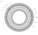
- FIG. 1 is a cross-sectional view showing the overall basic configuration of a permanent magnet type rotating electrical machine disclosed in the present application
- FIG. 4 is an enlarged conceptual diagram showing a cross section near the stator teeth of the permanent magnet type rotating electric machine according to Embodiment 1
- FIG. 2 is a cross-sectional view schematically showing magnetic flux generated from a stator magnet of the permanent magnet type rotating electric machine according to Embodiment 1
- FIG. 4 is a diagram showing analysis results of magnetic flux generated by a stator magnet of the permanent magnet type rotating electric machine according to Embodiment 1
- FIG. . 4 is a diagram showing a result of analyzing the torque of the permanent magnet type rotary electric machine according to the first embodiment
- FIG. 10 is an enlarged conceptual diagram showing a cross section near the stator teeth of the permanent magnet type rotary electric machine according to Embodiment 2;
- FIG. 10 is a cross-sectional view schematically showing magnetic flux generated from a stator magnet of the permanent magnet type rotating electric machine according to Embodiment 2;
- FIG. 9 is a diagram showing the result of analyzing the torque of the permanent magnet type rotating electric machine according to the second embodiment;
- FIG. 10 is a diagram showing results of analysis of torque of a permanent magnet type rotating electrical machine with another configuration according to Embodiment 2;
- FIG. 1 is a cross-sectional view showing the basic configuration of a permanent magnet type rotating electric machine disclosed in the present application. Using FIG. 1, first, the operation when this permanent magnet type rotating electrical machine is used as a generator will be described. In this application, a generator will be described as an example of a rotating electric machine, but the present invention can also be applied when used as an electric motor.
- a stator core 2 of a stator 1 has a plurality of stator slots 3, in which stator coils 4 are housed.
- the stator coil 4 is intensively wound around the stator teeth 5 .
- Stator magnets 6, which are permanent magnets, are stored in the stator slots 3, and the stator magnets 6 are all magnetized to have the same polarity in the radial direction. Therefore, if the stator magnet 6 is the north pole, the stator teeth 5 are the south pole, forming the same number of pole pairs NS as the number of the stator slots 3 .
- a first rotor 10 is provided across a gap from the stator 1, and the first rotor 10 has a configuration in which a plurality of magnetic pole pieces 11 are arranged in the circumferential direction. Let N L be the number of pole pieces.
- a second rotor 20 exists with an air gap from the first rotor 10 .
- the second rotor 20 has second rotor magnets (permanent magnets) 21 and forms N H pole pairs (the number of poles is 2N H ).
- the second rotor 20 will It rotates at a rotational speed of NL / NH times. In this way, the second rotor 20 rotates at a rotational speed NL / NH times that of the first rotor 10, so the permanent magnet type rotating electric machine disclosed in the present application has a magnetic speed change mechanism. It is called a permanent magnet type rotary electric machine.
- the magnetic flux generated from the second rotor magnet 21 interlinks with the stator coil 4, causing the stator coil 4 can generate an induced electromotive force, and if this is connected to a load, the generated power can be output from the stator coil 4 .
- the device dimensions of the rotating electric machine or the amount of permanent magnets to be used depends on the magnitude of the torque rather than the induced voltage. It turned out to be highly dependent. That is, by increasing the torque, it is possible to reduce the device size of the rotating electrical machine of the present application and reduce the amount of permanent magnets used.
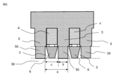
- FIG. 2 is an enlarged conceptual diagram showing a cross section near the stator teeth of the permanent magnet type rotating electric machine according to the first embodiment.
- FIG. 2 shows a portion including two stator slots 3 .
- a stator coil 4 is housed in the stator slot 3 and concentratedly wound around the stator teeth 5 .
- Stator magnets 6 are housed in the stator slots 3, and the stator magnets 6 are magnetized so that all the slots have the same polarity in the radial direction.
- the stator magnets 6 are arranged in the stator slots 3 on the side of the first air gap 30 from the stator coils 4 .
- stator teeth 5 The portion of the stator teeth 5 corresponding to the portion where the stator magnet 6 is arranged, that is, the position sandwiched between the stator magnets 6 arranged in the adjacent stator slots 3 as shown in FIG.
- the result of considering the stator teeth 50 at positions sandwiched between the adjacent stator magnets 6 will be described below.
- the circumferential width of the stator teeth 50 sandwiched between the adjacent stator magnets 6 is b, and the portion facing the first gap 30, that is, the gap surface of the stator teeth 5 is Let a be the pitch and c be the width of the stator slot 3 in the circumferential direction.
- the circumferential width of the stator teeth 50 at positions sandwiched between the adjacent stator magnets 6 is the same throughout the portion sandwiched between the adjacent stator magnets 6. .
- b/a ⁇ 100 [%] is 50% or less, that is, the adjacent stator magnets 6
- the circumferential width of the stator teeth 50 at the sandwiched position is set to be narrower than the circumferential width c of the stator slot.
- FIG. 3 is a diagram schematically showing the magnetic flux generated from the stator magnet 6 magnetized in the direction of the straight arrow.
- the magnetic flux generated from the stator magnet 6 reaches the pole piece 11 of the first rotor 10 through the first air gap 30, it becomes an effective magnetic flux that contributes to the torque.
- the magnetic flux generated from the stator magnet 6 actually reaches the stator teeth 5 through adjacent portions in the circumferential direction, as indicated by thin curved arrows in the drawing, and becomes leakage magnetic flux that does not contribute to torque.
- the magnetic flux generated from the stator magnet 6 leaks to the stator teeth 5 before reaching the magnetic pole piece 11 of the first rotor 10 as indicated by the thick curved arrow.
- the first rotor 10 is a structure having a plurality of magnetic pole pieces 11, compared with a general permanent magnet type rotating electric machine, As a result, the permeance coefficient of the stator magnet 6 tends to decrease. That is, there is a problem that a considerable amount of magnetic flux generated from the stator magnet 6 leaks to the stator teeth 5 along the route shown in FIG. This reduces the torque. In order to reduce this leakage magnetic flux, it is desirable to widen the distance between the stator teeth 50 sandwiched between the stator magnets 6 and the stator magnets 6 .
- FIG. 4 shows the electromagnetic field analysis results of the magnetic flux density from the stator magnet 6 on the surface of the first gap 30 of the first rotor 10 with respect to the stator tooth width/stator tooth pitch on the gap surface.
- FIG. 4 shows the result of analysis of the fundamental wave component of the magnetic flux of the stator magnet. The larger the magnetic flux of the fundamental wave component, the larger the effective magnetic flux contributing to the torque. As can be seen from FIG. 4, even with the same amount of magnets, the narrower the width of the stator teeth 5, the greater the effective magnetic flux that contributes to the torque.
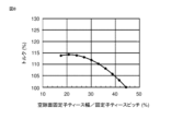
- FIG. 5 shows the electromagnetic field analysis results of the torque with respect to the stator tooth width/stator tooth pitch on the air gap surface of the stator teeth 5 .
- FIG. 5 shows the results of an analysis in which the stator magnet 6 is the same and the stator tooth width is changed, assuming that the torque is 100% when the stator tooth width/stator tooth pitch is 50%. It can be seen from the figure that the torque is improved when the width of the stator teeth 50 located between the stator magnets 6 is narrow. That is, by narrowing the width of the stator teeth 50 between the adjacent stator magnets 6 relative to the width of the stator slots 3 in the circumferential direction, the torque can be improved with the same amount of permanent magnets used and the same device dimensions. It can contribute to miniaturization of equipment.
- FIG. 6 is an enlarged conceptual diagram showing a cross section near the stator teeth of the permanent magnet type rotating electric machine according to the second embodiment.
- a stator coil 4 is housed in the stator slot 3 and concentratedly wound around the stator teeth 5 .
- Stator magnets 6 are housed in the stator slots 3, and the stator magnets 6 are magnetized so that all the slots have the same polarity in the radial direction.
- the stator magnets 6 are arranged in slots closer to the first air gap 30 than the stator coils 4 are.
- the width of the stator slot 3 gradually widens toward the gap side, and at least on the gap surface, the width of the stator teeth is the same as the slot opening. is narrower than the width of However, the circumferential width of the stator teeth 50 sandwiched between the adjacent stator magnets 6 on the outermost side, that is, on the side near the bottom of the stator slot 3 is the width of the stator slot 3 at the same radial position. Narrower than wide is preferred.
- Embodiment 1 From the description of Embodiment 1, it was shown that the torque is improved by making the stator tooth width narrower than the stator slot width. As shown in FIG. 7, the magnetic flux generated from the stator magnet passes through the stator teeth 50 sandwiched between the adjacent stator magnets 6 and is superimposed on the magnetic flux (main magnetic flux) from the second rotor magnet 21. do. Therefore, the stator teeth 50 located between the adjacent stator magnets 6 are likely to be magnetically saturated. There is a problem that the induced voltage obtained by the magnetic flux interlinking with the stator coil 4 is reduced due to the magnetic saturation of the stator teeth 5 .
- stator teeth 50 located between the adjacent stator magnets 6 and reducing leakage magnetic flux from the stator magnets 6
- the cross-sectional area of the stator teeth 5 can be increased on the anti-air gap side of the stator magnets 6 (the side close to the stator coil). Saturation can be alleviated. Therefore, it is possible to increase the torque by reducing the leakage magnetic flux while mitigating the decrease in the induced voltage.
- FIG. 8 shows the electromagnetic field analysis results for a shape in which the width of the stator teeth 50 gradually decreases toward the inner circumference.
- the width of the stator teeth at the position closest to the stator coil 4 is fixed to 44.5% of the stator tooth pitch, and the stator The magnet 6 is the same, and shows the torque when the stator tooth width on the air gap surface is changed.
- FIG. 8 shows the torque as 100% when the width of the stator teeth 50 sandwiched between adjacent stator magnets is 44.5% of the stator tooth pitch in the entire radial direction. From the figure, it can be seen that the torque is improved while the influence of magnetic saturation of the stator teeth is reduced as much as possible. That is, in the stator teeth 50 sandwiched between the adjacent stator magnets, the torque is improved by gradually widening the stator slot width toward the air gap surface, thereby reducing the amount of permanent magnets used and the size of the device. is possible.
- the circumferential width of the stator teeth 50 at the position sandwiched between the stator magnets at the position closest to the stator coil 4 (the outermost side) is narrower than the circumferential width of the stator slot at the same radial position. That is, although it is preferably less than 50% of the stator tooth pitch, it is not limited to this.
- the width of the stator teeth 50 at the position closest to the stator coil 4 among the stator teeth 50 sandwiched between adjacent stator magnets is FIG. 9 shows the result of electromagnetic field analysis of torque when the stator tooth pitch is fixed at 57.7%, the stator magnet 6 is the same, and the stator tooth width on the air gap surface is changed.
- FIG. 9 shows the torque as 100% when the width of the stator teeth 50 sandwiched between adjacent stator magnets is 57.7% of the stator tooth pitch in the entire radial direction. From the figure, even if the circumferential width of the stator teeth at the position closest to the stator coil 4 among the positions sandwiched between adjacent stator magnets is 50% or more of the stator tooth pitch (that is, fixed (Even if the circumferential width of the stator teeth 50 located between the child magnets closest to the stator coil 4 is wider than the circumferential width of the stator slot at the same radial position). It can be seen that the effect of
- Embodiment 3 As shown in FIGS. 2 and 6, the width of the stator magnet 6 is configured so as to move away from the stator teeth toward the air gap side. , the distance between the stator magnet 6 and the stator teeth 50 sandwiched between the adjacent stator magnets can be further increased, thereby improving the torque.
- stator 1 stator, 2 stator core, 3 stator slots, 4 stator coils, 5 stator teeth, 6 stator magnets, 10 first rotor, 11 pole pieces, 20 second rotor, 21 second rotor magnets (permanent magnets), 50 stator teeth located between adjacent stator magnets
Abstract
固定子ティース(5)を周方向に複数備えた固定子鉄心(2)と、固定子ティース(5)の間に形成された複数の固定子スロット(3)のそれぞれの底部の側に配置され、固定子ティース(5)に集中巻きされた固定子コイル(4)と、複数の固定子スロット(3)のそれぞれの開口した側に配置された固定子磁石(6)と、を備えた固定子(1)と、複数の磁極片(11)を有し、固定子磁石(6)と対向して固定子(1)と同軸に設けられた第1の回転子(10)と、複数の永久磁石を有し、第1の回転子(10)と対向して第1の回転子(10)と同軸に設けられた第2の回転子(20)と、を備えた永久磁石回転電機において、隣り合う2つの固定子磁石に挟まれた位置の固定子ティース(50)の周方向の幅が、固定子スロット(3)の周方向の幅よりも狭い。
Description
本願は、永久磁石式回転電機に関するものである。
固定子と回転子とが接触していない状態で回転子の回転速度を変更することができる回転電機がある。例えば、特許文献1には、このような磁気波動歯車装置である回転電機が開示されている。特許文献1に開示されている磁気波動歯車装置は、固定子、低速で回転する第1の回転子および変速比に応じて高速で回転する第2の回転子を備えている。固定子、第1の回転子および第2の回転子は、回転軸を中心に順に外周側から配置されている。固定子は、固定子コイルを含んでいる。固定子コイルは、発電した電力を出力するためのコイル、または発生したトルクを制御するためのコイルである。
特許文献1に開示されている磁気波動歯車装置によれば、第1の回転子および第2の回転子が固定子に接触していない状態で第2の回転子の速度が変えられるため、機械式の変速機が不要となり、機械的な摩耗などに対応するためのメンテナンス負荷を軽減することができる。
特許文献1に開示されている回転電機は、固定子に複数の固定子スロットを有し、各固定子スロットには固定子コイルと固定子磁石(永久磁石)が格納されている。固定子磁石は各固定子スロットで同方向に着磁されている。固定子の内周側に複数の磁極片を周方向に並べた第1の回転子が配置されており、この第1の回転子の内周側に永久磁石を有する第2の回転子が配置されている。固定子の固定子スロット数(=固定子ティース数)をNS、第1の回転子の磁極片の数をNL、第2の回転子の極対数をNHとすると、以下の数式の関係が成り立っている。
NL=NS+NH
このとき、第2の回転子は第1の回転子のNL/NH倍の速度で回転する。
NL=NS+NH
このとき、第2の回転子は第1の回転子のNL/NH倍の速度で回転する。
しかしながら、特許文献1に開示されている回転電機では、固定子コイルは、分布巻で固定子に巻回されている。分布巻で巻き回された固定子コイルは、容量が大きくなり固定子の径が大きくなると、固定子コイルの工作性が低下する。このため、回転電機の容量が大きくなる場合には、固定子コイルの工作性が低下する。一方、集中巻によって巻き回された固定子コイルの場合、容量が大きくなっても固定子コイルの工作性の低下が抑制される。このため、固定子コイルの工作性の低下の抑制のためには、回転電機の固定子コイルは集中巻によって巻回されることが好ましい。
特許文献1に開示されている回転電機を発電機として動作させる場合、第1の回転子を外部動力により回転させると、固定子磁石の磁力および第2の回転子の磁石による磁力が第1の回転子の複数の磁極片により変調され、第2の回転子を増速して回転させる。この増速した第2の回転子の永久磁石から発生する磁力が固定子コイルに鎖交することで、固定子コイルに発電電力を誘起することになる。すなわち、第2の回転子の回転数を高くする、あるいは第2の回転子から固定子までの空隙を狭くして第2の回転子の永久磁石の磁力をより多く固定子コイルに鎖交させることで、誘起電圧が増加し発電電力が増加することになる。
入力は第1の回転子を外部動力により回転させることにより発生する。すなわち、第1の回転子の回転数×第1の回転子に働くトルクとなる。固定子磁石による磁力と第2の回転子の永久磁石による磁力が第1の回転子の磁極片により変調されることで第1の回転子にトルクが発生するため、必要となる出力を得るためにはこの第1の回転子に発生するトルクを回転数によって決まる所定の値にする必要がある。すなわち、第1の回転子に発生するトルクを増大することで、大容量化が可能となる。
一般に、メガワットクラスの大容量発電機を考えると、装置寸法あるいは永久磁石の使用量は、上述の固定子コイルに第2の回転子から発生した鎖交磁束および第2の回転子の回転数に比例する誘導起電力(以後、誘起電圧という)ではなく、第1の回転子に発生するトルクの大きさによって大きく影響を受けることが明らかになった。すなわち、誘起電圧を増加させてもトルクが減少すれば、装置寸法あるいは永久磁石の使用量が増大することになる。
特許文献2に示される磁気ギアードモータは、構成は特許文献1と同じであるが、固定子スロット内に格納された固定子磁石を周方向左右に2分割し、かつ着磁方向を逆方向としている。こうすることで、固定子磁石が作る極対数NSを各スロットことに同方向に着磁した場合より大きく取ることができ、第1の回転子の磁極片数を適切に構成することで、増減速比が大きくなり、発電機として使用した場合、誘起電圧が大きくなる。しかしながら、固定子磁石の体積を等しくした各スロットの固定子磁石を同方向に着磁した構成と比較して、1つの固定子磁石から発生する磁力が減少するため、トルクが減少するという問題がある。
本願は、上記のような問題点を解決するためになされたものであり、固定子コイルを集中巻きで構成し、固定子磁石を各スロットで同方向に着磁した永久磁石式回転電機において、発生トルクを向上させることを目的とする。
本願に開示される永久磁石式回転電機は、固定子ティースを周方向に複数備えた固定子鉄心と、前記固定子ティースの間に形成された複数の固定子スロットのそれぞれの底部の側に配置され、前記固定子ティースに集中巻きされた固定子コイルと、複数の前記固定子スロットのそれぞれの開口した側に配置され、径方向に同一の極性を備えた固定子磁石と、を備えた固定子と、複数の磁極片を有し、前記固定子磁石と対向して前記固定子と同軸に設けられた第1の回転子と、複数の永久磁石を有し、前記第1の回転子と対向して前記第1の回転子と同軸に設けられた第2の回転子と、を備えた永久磁石式回転電機において、複数の前記固定子スロットのうち隣り合う固定子スロットに配置された前記固定子磁石に挟まれた位置の前記固定子ティースの周方向の幅が、前記固定子スロットの周方向の幅よりも狭いものである。
本願によれば、固定子コイルを集中巻きで構成し、固定子磁石を各スロットで同方向に着磁した永久磁石式回転電機において、発生トルクを向上させることができる。
実施の形態1.
図1は、本願で開示する永久磁石式回転電機の基本構成を示す断面図である。図1を用いて、まずこの永久磁石式回転電機を発電機として用いた場合の動作を説明する。なお、本願では回転電機として発電機を例に説明するが、電動機として使用する場合にも適用できる。
図1は、本願で開示する永久磁石式回転電機の基本構成を示す断面図である。図1を用いて、まずこの永久磁石式回転電機を発電機として用いた場合の動作を説明する。なお、本願では回転電機として発電機を例に説明するが、電動機として使用する場合にも適用できる。
図1において、固定子1の固定子鉄心2には複数の固定子スロット3があり、この固定子スロット3内に固定子コイル4が格納されている。この固定子コイル4は、固定子ティース5に集中的に巻回されている。固定子スロット3には、永久磁石である固定子磁石6が格納されており、この固定子磁石6はすべて径方向に同一の極性の極となるように着磁されている。このため、固定子磁石6をN極とすれば、固定子ティース5がS極となり、固定子スロット3の数と同じ数の極対数NSを形成する。
上記の固定子1に対して空隙を隔てて第1の回転子10があり、第1の回転子10は周方向に複数の磁極片11を並べた構成となっている。磁極片の数をNLとする。第1の回転子10に対して空隙を隔てて第2の回転子20が存在する。この第2の回転子20は、第2の回転子磁石(永久磁石)21を有し、NHの極対数を形成する(極数は2NH)。
このとき、
NL=NS+NH (1)
であれば、固定子磁石6と第2の回転子磁石21の磁力の相互作用により、第1の回転子10にトルクが発生し、これに対して第1の回転子10を外部動力により回転させることで、第1の回転子10に入力を得ることができる。
NL=NS+NH (1)
であれば、固定子磁石6と第2の回転子磁石21の磁力の相互作用により、第1の回転子10にトルクが発生し、これに対して第1の回転子10を外部動力により回転させることで、第1の回転子10に入力を得ることができる。
第1の回転子10の入力に対して、第2の回転子20をフリーランさせるように固定子コイル4に固定子電流を流せば、第2の回転子20は第1の回転子10のNL/NH倍の回転速度で回転する。このように、第2の回転子20が第1の回転子10のNL/NH倍の回転速度で回転するため、本願で開示する永久磁石式回転電機は、磁気的な変速機構を有する永久磁石式回転電機と称する。第2の回転子20が第1の回転子10のNL/NH倍速で回転すると、第2の回転子磁石21から発生する磁束が固定子コイル4に鎖交することで、固定子コイル4に誘導起電力を発生させることができ、これを負荷に接続すれば固定子コイル4から発電電力を出力させることができる。
この磁気的な変速機構を有する永久磁石式回転電機において発電電力の出力を増加させるためには、無負荷時において固定子コイル4に発生する誘起電圧を増大させる必要があることがわかる。固定子コイル4に発生する誘起電圧を増大させるには、第2の回転子磁石21から発生し、固定子コイル4の鎖交する磁束量を増大させる方法と、固定子コイル4に鎖交する磁束の周波数を高くすることが有効であることがわかる。前者は第2の回転子の磁石使用量を増大させる、第2の回転子20と固定子1間の空隙(第1の回転子10を挟んで、第1の空隙30と第2の空隙40の2か所存在する)を縮小する、などの方法が考えられる。後者については、増速比(NL/NH)が大きくなるように設計することが考えられる。
しかし、このような磁気的な変速機構を有する永久磁石式回転電機では、出力を増大させるためには入力、すなわち第1の回転子10に発生するトルクを増大させる必要がある。第1の回転子10に発生するトルクは、固定子コイル4の電流にはほとんど関係がなく、固定子磁石6による磁束と第2の回転子磁石21による磁束の第1の回転子10の磁極片11との相互作用によって発生する。よって、このような永久磁石式回転電機が出力を得るために必要となる、回転電機の装置寸法、あるいは使用する永久磁石量は誘起電圧の大きさとトルクの大きさの両方の影響で決定されることになる。もちろん、回転電機の装置寸法は小さい方が優れており、使用する永久磁石量も少ない方が地球環境の保護の面からも優れていることは言うまでもない。
本願で開示する磁気的な変速機構を有する永久磁石式回転電機において、出力がメガワットクラスの大容量を想定すると、回転電機の装置寸法あるいは使用する永久磁石量は、誘起電圧よりトルクの大きさに大きく依存していることが判明した。すなわち、トルクを増大することで本願の回転電機の装置寸法を縮小し、使用する永久磁石量を低減できることになる。
実施の形態1.
図2は実施の形態1による永久磁石式回転電機の固定子ティース付近の断面を示す拡大概念図である。図2では、固定子スロット3を2個含む部分を示している。固定子スロット3内には固定子コイル4が格納されており、固定子ティース5に集中巻きされている。固定子スロット3には、固定子磁石6が格納されており、この固定子磁石6は各スロットで全て径方向に同一の極性の極となるように着磁されている。固定子磁石6は固定子コイル4より第1の空隙30の側の固定子スロット3内に配置されている。この固定子磁石6が配置されている部分に対応する固定子ティース5の部分、すなわち図2に示すように隣り合う固定子スロット3に配置されたそれぞれの固定子磁石6に挟まれた位置(隣り合う固定子磁石6に挟まれた位置)の固定子ティース50について考察した結果を以下に説明する。
図2は実施の形態1による永久磁石式回転電機の固定子ティース付近の断面を示す拡大概念図である。図2では、固定子スロット3を2個含む部分を示している。固定子スロット3内には固定子コイル4が格納されており、固定子ティース5に集中巻きされている。固定子スロット3には、固定子磁石6が格納されており、この固定子磁石6は各スロットで全て径方向に同一の極性の極となるように着磁されている。固定子磁石6は固定子コイル4より第1の空隙30の側の固定子スロット3内に配置されている。この固定子磁石6が配置されている部分に対応する固定子ティース5の部分、すなわち図2に示すように隣り合う固定子スロット3に配置されたそれぞれの固定子磁石6に挟まれた位置(隣り合う固定子磁石6に挟まれた位置)の固定子ティース50について考察した結果を以下に説明する。
図2に示すように、隣り合う固定子磁石6に挟まれた位置の固定子ティース50の周方向の幅をb、第1の空隙30に面した部分、すなわち空隙面における固定子ティース5のピッチをa、固定子スロット3の周方向の幅をcとする。なお、本実施の形態1における、隣り合う固定子磁石6に挟まれた位置の固定子ティース50の周方向幅は、隣り合う固定子磁石6に挟まれた部分全体で同じ幅になっている。固定子ティース幅の固定子ティースピッチに対する割合 b/a×100 [%]とすると、本実施の形態1ではb/a×100 [%]を50%以下、すなわち、隣り合う固定子磁石6に挟まれた位置の固定子ティース50の周方向の幅が固定子スロットの周方向の幅cよりも狭い幅に設定する。
図3は、直線の矢印の方向に着磁された固定子磁石6から発生する磁束を模式的に示した図である。固定子磁石6から発生する磁束は、第1の空隙30を介して第1の回転子10の磁極片11に到達するとトルクに寄与する有効な磁束となる。しかし、固定子磁石6から発生する磁束は、実際には図の細い曲線矢印で示すように、周方向に隣接する部分を通して固定子ティース5に到達し、トルクには寄与しない漏れ磁束となる。また、第1の空隙30においても固定子磁石6から発生する磁束が太い曲線の矢印で示すように第1の回転子10の磁極片11に到達する前に固定子ティース5に漏れてしまう。
本願のような、磁気的な変速機構を有する永久磁石式回転電機においては、第1の回転子10が複数の磁極片11を有する構造体であるため、一般の永久磁石式回転電機と比較して固定子磁石6のパーミアンス係数が低くなる傾向にある。すなわち、固定子磁石6から発生する磁束は、図3に図示した経路で固定子ティース5にかなり多く漏れるという問題がある。これにより、トルクが減少していた。この漏れ磁束を低減するためには、固定子磁石6に挟まれた位置の固定子ティース50と固定子磁石6の距離を広く取ることが望ましいことがわかる。
図4に空隙面における固定子ティース幅/固定子ティースピッチに対する第1の回転子10の第1の空隙30表面における固定子磁石6からの磁束密度の電磁界解析結果を示す。図4は、固定子磁石の磁束の基本波成分を解析した結果を示しており、基本波成分の磁束が大きいほどトルクに寄与する有効磁束が大きくなる。図4より、同じ磁石量であっても固定子ティース5の幅が狭い方がトルクに寄与する有効磁束が増加することがわかる。
固定子ティース5の空隙面における固定子ティース幅/固定子ティースピッチに対するトルクの電磁界解析結果を図5に示す。図5は、固定子ティース幅/固定子ティースピッチが50%におけるトルクを100%として、固定子磁石6は同一で、固定子ティース幅を変化させて解析した結果を示したものである。同図より、固定子磁石6に挟まれた位置の固定子ティース50の幅が狭い方でトルクが向上していることがわかる。すなわち、隣り合う固定子磁石6に挟まれた位置の固定子ティース50の幅を固定子スロット3の周方向幅より狭くすることで、同一の永久磁石使用量および同一装置寸法でトルクを向上することができ、機器の小型化に貢献できる。
実施の形態2.
図6は実施の形態2による永久磁石式回転電機の固定子ティース付近の断面を示す拡大概念図である。固定子スロット3内には固定子コイル4が格納されており、固定子ティース5に集中巻きされている。固定子スロット3には、固定子磁石6が格納されており、この固定子磁石6は各スロットですべて径方向に同一の極性の極となるように着磁されている。固定子磁石6は固定子コイル4より第1の空隙30側のスロット内に配置されている。
図6は実施の形態2による永久磁石式回転電機の固定子ティース付近の断面を示す拡大概念図である。固定子スロット3内には固定子コイル4が格納されており、固定子ティース5に集中巻きされている。固定子スロット3には、固定子磁石6が格納されており、この固定子磁石6は各スロットですべて径方向に同一の極性の極となるように着磁されている。固定子磁石6は固定子コイル4より第1の空隙30側のスロット内に配置されている。
隣り合う固定子磁石6に挟まれた位置の固定子ティース50において、固定子スロット3の幅が空隙側に向かって徐々に広くなっており、少なくとも空隙面においては固定子ティース幅がスロット開口部の幅より狭くなっている。ただし、隣り合う固定子磁石6に挟まれた位置の固定子ティース50の最も外周側、すなわち固定子スロット3の底に近い側における周方向の幅が、同一径方向位置における固定子スロット3の幅よりも狭いことが好ましい。
実施の形態1の説明より、固定子ティース幅を固定子スロット幅より狭くすることで、トルクが向上することを示した。図7に示すように固定子磁石から発生する磁束は、隣り合う固定子磁石6に挟まれた位置の固定子ティース50を通り、第2の回転子磁石21からの磁束(主磁束)と重畳する。このため、隣り合う固定子磁石6に挟まれた位置の固定子ティース50は磁気飽和を起こしやすく、固定子ティース幅が狭い(固定子スロット幅が広い)ほど、第2の回転子20からの磁束が固定子コイル4に鎖交することによって得られる誘起電圧が固定子ティース5の磁気飽和により減少するという問題がある。
隣り合う固定子磁石6に挟まれた位置の固定子ティース50における磁気飽和を緩和し、かつ固定子磁石6からの漏れ磁束を低減する構成として、隣り合う固定子磁石6に挟まれた位置の固定子ティース50の幅を空隙に向かって徐々に狭くすることで、固定子磁石6の反空隙側(固定子コイルに近い側)で固定子ティース5の断面積を大きく取ることができるため磁気飽和を緩和させることができる。よって、誘起電圧の減少を緩和しつつ漏れ磁束を低減できることでトルクを増大させることができる。
固定子ティース50の幅が内周側に向けて漸次減少する形状における電磁界解析結果を図8に示す。図8は、隣り合う固定子磁石に挟まれた位置の固定子ティース50のうち最も固定子コイル4側の位置における固定子ティース幅を固定子ティースピッチの44.5%に固定し、固定子磁石6は同一で、空隙面における固定子ティース幅を変化させた場合のトルクを示している。図8では、隣り合う固定子磁石に挟まれた位置の固定子ティース50の幅が径方向全体で固定子ティースピッチの44.5%である場合のトルクを100%として示している。同図より、固定子ティースの磁気飽和による影響を極力緩和しつつ、トルクが向上することがわかる。すなわち、隣り合う固定子磁石に挟まれた位置の固定子ティース50において、空隙面に向かって固定子スロット幅を徐々に広げることでトルクが向上し、永久磁石の使用量削減および装置寸法の縮小が可能となることがわかる。
固定子磁石に挟まれた位置の固定子ティース50の最も固定子コイル4側(最も外周側)における周方向の幅が、同一の径方向位置における固定子スロットの周方向の幅よりも狭い、すなわち固定子ティースピッチの50%未満であることが好ましいが、それに限らない。固定子ティース50の幅が内周側に向けて漸次減少する形状において、隣り合う固定子磁石に挟まれた位置の固定子ティース50のうち最も固定子コイル4側の位置における固定子ティース幅を固定子ティースピッチの57.7%に固定し、固定子磁石6は同一で、空隙面における固定子ティース幅を変化させた場合のトルクの電磁界解析結果を図9に示す。図9では、隣り合う固定子磁石に挟まれた位置の固定子ティース50の幅が径方向全体で固定子ティースピッチの57.7%である場合のトルクを100%として示している。同図より、隣り合う固定子磁石に挟まれた位置のうち最も固定子コイル4側の位置の固定子ティースの周方向の幅が固定子ティースピッチの50%以上であっても(すなわち、固定子磁石に挟まれた位置の固定子ティース50の最も固定子コイル4側における周方向の幅が、同一の径方向位置における固定子スロットの周方向の幅よりも広い場合であっても)同様の効果を奏することがわかる。
実施の形態3.
図2および図6に示したように、固定子磁石6の幅を空隙側に向かって固定子ティースから遠ざけるように構成する、すなわち、固定子磁石6の形状を周方向の幅が内周側に向けて漸次減少する形状とすることで、固定子磁石6と、隣り合う固定子磁石に挟まれた位置の固定子ティース50との距離をさらに広げることができ、トルクが向上する。
図2および図6に示したように、固定子磁石6の幅を空隙側に向かって固定子ティースから遠ざけるように構成する、すなわち、固定子磁石6の形状を周方向の幅が内周側に向けて漸次減少する形状とすることで、固定子磁石6と、隣り合う固定子磁石に挟まれた位置の固定子ティース50との距離をさらに広げることができ、トルクが向上する。
本願には、様々な例示的な実施の形態及び実施例が記載されているが、1つ、または複数の実施の形態に記載された様々な特徴、態様、及び機能は特定の実施の形態の適用に限られるのではなく、単独で、または様々な組み合わせで実施の形態に適用可能である。従って、例示されていない無数の変形例が、本願明細書に開示される技術の範囲内において想定される。例えば、少なくとも1つの構成要素を変形する場合、追加する場合または省略する場合、さらには、少なくとも1つの構成要素を抽出し、他の実施の形態の構成要素と組み合わせる場合が含まれるものとする。
1 固定子、2 固定子鉄心、3 固定子スロット、4 固定子コイル、5 固定子ティース、6 固定子磁石、10 第1の回転子、11 磁極片、20 第2の回転子、21 第2の回転子磁石(永久磁石)、50 隣り合う固定子磁石に挟まれた位置の固定子ティース
Claims (5)
- 固定子ティースを周方向に複数備えた固定子鉄心と、前記固定子ティースの間に形成された複数の固定子スロットのそれぞれの底部の側に配置され、前記固定子ティースに集中巻きされた固定子コイルと、複数の前記固定子スロットのそれぞれの開口した側に配置され、径方向に同一の極性を備えた固定子磁石と、を備えた固定子と、
複数の磁極片を有し、前記固定子磁石と対向して前記固定子と同軸に設けられた第1の回転子と、
複数の永久磁石を有し、前記第1の回転子と対向して前記第1の回転子と同軸に設けられた第2の回転子と、を備えた永久磁石式回転電機において、
複数の前記固定子スロットのうち隣り合う固定子スロットに配置された前記固定子磁石に挟まれた位置の前記固定子ティースの周方向の幅が、前記固定子スロットの周方向の幅よりも狭い永久磁石式回転電機。 - 固定子ティースを周方向に複数備えた固定子鉄心と、前記固定子ティースの間に形成された複数の固定子スロットのそれぞれの底部の側に配置され、前記固定子ティースに集中巻きされた固定子コイルと、複数の前記固定子スロットのそれぞれの開口した側に配置され、径方向に同一の極性を備えた固定子磁石と、を備えた固定子と、
複数の磁極片を有し、前記固定子磁石と対向して前記固定子と同軸に設けられた第1の回転子と、
複数の永久磁石を有し、前記第1の回転子と対向して前記第1の回転子と同軸に設けられた第2の回転子と、を備えた永久磁石式回転電機において、
前記第1の回転子に面した位置において、前記固定子ティースの周方向の幅が、前記固定子スロットの周方向の幅よりも狭く、複数の前記固定子スロットのうち隣り合う固定子スロットに配置された前記固定子磁石に挟まれた位置の前記固定子ティースの周方向の幅が、内周側に向けて漸次減少している永久磁石式回転電機。 - 前記固定子磁石に挟まれた位置の前記固定子ティースの最も外周側における周方向の幅が、同一の径方向位置における前記固定子スロットの周方向の幅よりも狭い請求項2に記載の永久磁石式回転電機。
- 前記固定子磁石は、周方向の幅が内周側に向けて漸次減少している請求項1から3のいずれか1項に記載の永久磁石式回転電機。
- 前記固定子の固定子スロット数NS、前記第1の回転子の磁極片の数NL、前記第2の回転子の極対数NHが、NL=NS+NHである請求項1から4のいずれか1項に記載の永久磁石式回転電機。
Priority Applications (2)
| Application Number | Priority Date | Filing Date | Title |
|---|---|---|---|
| PCT/JP2021/042377 WO2023089721A1 (ja) | 2021-11-18 | 2021-11-18 | 永久磁石式回転電機 |
| JP2022520035A JP7090828B1 (ja) | 2021-11-18 | 2021-11-18 | 永久磁石式回転電機 |
Applications Claiming Priority (1)
| Application Number | Priority Date | Filing Date | Title |
|---|---|---|---|
| PCT/JP2021/042377 WO2023089721A1 (ja) | 2021-11-18 | 2021-11-18 | 永久磁石式回転電機 |
Publications (1)
| Publication Number | Publication Date |
|---|---|
| WO2023089721A1 true WO2023089721A1 (ja) | 2023-05-25 |
Family
ID=82155946
Family Applications (1)
| Application Number | Title | Priority Date | Filing Date |
|---|---|---|---|
| PCT/JP2021/042377 WO2023089721A1 (ja) | 2021-11-18 | 2021-11-18 | 永久磁石式回転電機 |
Country Status (2)
| Country | Link |
|---|---|
| JP (1) | JP7090828B1 (ja) |
| WO (1) | WO2023089721A1 (ja) |
Families Citing this family (1)
| Publication number | Priority date | Publication date | Assignee | Title |
|---|---|---|---|---|
| JP2024027830A (ja) * | 2022-08-19 | 2024-03-01 | 三菱重工業株式会社 | 可変速動力装置及び制御方法 |
Citations (7)
| Publication number | Priority date | Publication date | Assignee | Title |
|---|---|---|---|---|
| WO2014128985A1 (ja) * | 2013-02-22 | 2014-08-28 | 株式会社Ihi | 磁気波動歯車装置 |
| WO2015178111A1 (ja) * | 2014-05-20 | 2015-11-26 | 株式会社Ihi | 磁気波動歯車装置 |
| JP2016135014A (ja) | 2015-01-20 | 2016-07-25 | 株式会社Ihi | 磁気波動歯車装置 |
| CN106165275A (zh) * | 2014-09-03 | 2016-11-23 | 朝鲜大学校产学协力团 | 凸极式磁齿轮 |
| WO2020174936A1 (ja) | 2019-02-26 | 2020-09-03 | パナソニックIpマネジメント株式会社 | 磁気ギアードモータ |
| WO2021149473A1 (ja) * | 2020-01-24 | 2021-07-29 | 三菱重工業株式会社 | 磁気ギアード回転電機 |
| JP2021151156A (ja) * | 2020-03-23 | 2021-09-27 | パナソニックIpマネジメント株式会社 | 回転電機 |
-
2021
- 2021-11-18 JP JP2022520035A patent/JP7090828B1/ja active Active
- 2021-11-18 WO PCT/JP2021/042377 patent/WO2023089721A1/ja active Application Filing
Patent Citations (7)
| Publication number | Priority date | Publication date | Assignee | Title |
|---|---|---|---|---|
| WO2014128985A1 (ja) * | 2013-02-22 | 2014-08-28 | 株式会社Ihi | 磁気波動歯車装置 |
| WO2015178111A1 (ja) * | 2014-05-20 | 2015-11-26 | 株式会社Ihi | 磁気波動歯車装置 |
| CN106165275A (zh) * | 2014-09-03 | 2016-11-23 | 朝鲜大学校产学协力团 | 凸极式磁齿轮 |
| JP2016135014A (ja) | 2015-01-20 | 2016-07-25 | 株式会社Ihi | 磁気波動歯車装置 |
| WO2020174936A1 (ja) | 2019-02-26 | 2020-09-03 | パナソニックIpマネジメント株式会社 | 磁気ギアードモータ |
| WO2021149473A1 (ja) * | 2020-01-24 | 2021-07-29 | 三菱重工業株式会社 | 磁気ギアード回転電機 |
| JP2021151156A (ja) * | 2020-03-23 | 2021-09-27 | パナソニックIpマネジメント株式会社 | 回転電機 |
Also Published As
| Publication number | Publication date |
|---|---|
| JP7090828B1 (ja) | 2022-06-24 |
| JPWO2023089721A1 (ja) | 2023-05-25 |
Similar Documents
| Publication | Publication Date | Title |
|---|---|---|
| KR100899913B1 (ko) | 모터 | |
| TWI420783B (zh) | Axial motor | |
| JP4071510B2 (ja) | 電動機 | |
| CN111149281B (zh) | 永久磁铁式旋转电机 | |
| WO2011111357A1 (ja) | モータ | |
| JP4369384B2 (ja) | 回転電機 | |
| JP2007074870A (ja) | 永久磁石埋込型ロータおよび永久磁石埋込型モータ | |
| WO2021149473A1 (ja) | 磁気ギアード回転電機 | |
| JP6048191B2 (ja) | マルチギャップ型回転電機 | |
| WO2015097767A1 (ja) | 永久磁石式回転電機 | |
| JP2006304546A (ja) | 永久磁石式リラクタンス型回転電機 | |
| JP6212117B2 (ja) | 同期電動機 | |
| JP2003284276A (ja) | 回転電機 | |
| WO2023089721A1 (ja) | 永久磁石式回転電機 | |
| JPH11206085A (ja) | 永久磁石電動機 | |
| JP3655205B2 (ja) | 回転電機とそれを用いた電動車両 | |
| JP6035957B2 (ja) | 回転機 | |
| EP3661034B1 (en) | Rotary electric machine | |
| JP2007318860A5 (ja) | ||
| WO2012081392A1 (ja) | 回転電機 | |
| JP6191375B2 (ja) | 電動発電機及びそれを備えたエンジンユニット | |
| JP2010284022A (ja) | 永久磁石型回転機 | |
| WO2021182088A1 (ja) | 永久磁石同期モータ | |
| JP4216369B2 (ja) | ステッピングモータ | |
| JP7258100B1 (ja) | 回転電機 |
Legal Events
| Date | Code | Title | Description |
|---|---|---|---|
| WWE | Wipo information: entry into national phase |
Ref document number: 2022520035 Country of ref document: JP |
|
| 121 | Ep: the epo has been informed by wipo that ep was designated in this application |
Ref document number: 21964736 Country of ref document: EP Kind code of ref document: A1 |