EP4080743B1 - Elektrische drehmaschine mit magnetgetriebe - Google Patents
Elektrische drehmaschine mit magnetgetriebe Download PDFInfo
- Publication number
- EP4080743B1 EP4080743B1 EP21743641.9A EP21743641A EP4080743B1 EP 4080743 B1 EP4080743 B1 EP 4080743B1 EP 21743641 A EP21743641 A EP 21743641A EP 4080743 B1 EP4080743 B1 EP 4080743B1
- Authority
- EP
- European Patent Office
- Prior art keywords
- stator
- tooth
- rotor
- electric machine
- coil
- Prior art date
- Legal status (The legal status is an assumption and is not a legal conclusion. Google has not performed a legal analysis and makes no representation as to the accuracy of the status listed.)
- Active
Links
Images




Classifications
-
- H—ELECTRICITY
- H02—GENERATION; CONVERSION OR DISTRIBUTION OF ELECTRIC POWER
- H02K—DYNAMO-ELECTRIC MACHINES
- H02K7/00—Arrangements for handling mechanical energy structurally associated with dynamo-electric machines, e.g. structural association with mechanical driving motors or auxiliary dynamo-electric machines
- H02K7/10—Structural association with clutches, brakes, gears, pulleys or mechanical starters
- H02K7/11—Structural association with clutches, brakes, gears, pulleys or mechanical starters with dynamo-electric clutches
-
- H—ELECTRICITY
- H02—GENERATION; CONVERSION OR DISTRIBUTION OF ELECTRIC POWER
- H02K—DYNAMO-ELECTRIC MACHINES
- H02K16/00—Machines with more than one rotor or stator
- H02K16/02—Machines with one stator and two or more rotors
-
- H—ELECTRICITY
- H02—GENERATION; CONVERSION OR DISTRIBUTION OF ELECTRIC POWER
- H02K—DYNAMO-ELECTRIC MACHINES
- H02K21/00—Synchronous motors having permanent magnets; Synchronous generators having permanent magnets
- H02K21/38—Synchronous motors having permanent magnets; Synchronous generators having permanent magnets with rotating flux distributors, and armatures and magnets both stationary
- H02K21/44—Synchronous motors having permanent magnets; Synchronous generators having permanent magnets with rotating flux distributors, and armatures and magnets both stationary with armature windings wound upon the magnets
-
- H—ELECTRICITY
- H02—GENERATION; CONVERSION OR DISTRIBUTION OF ELECTRIC POWER
- H02K—DYNAMO-ELECTRIC MACHINES
- H02K49/00—Dynamo-electric clutches; Dynamo-electric brakes
- H02K49/10—Dynamo-electric clutches; Dynamo-electric brakes of the permanent-magnet type
- H02K49/102—Magnetic gearings, i.e. assembly of gears, linear or rotary, by which motion is magnetically transferred without physical contact
Definitions
- the present disclosure relates to a magnetic geared rotary electric machine.
- Patent Document 1 discloses a magnetic geared rotary electric machine in which a low-speed rotor (first rotor), a high-speed rotor (second rotor), and a stator are coaxially rotatable relative to each other.
- the magnetic geared rotary electric machine When used as, for example, a motor, the low-speed rotor which is an output shaft rotates at a predetermined reduction ratio due to a harmonic magnetic flux by rotating the high-speed rotor by an electromotive force of a coil provided in the stator.
- the stator includes a stator core and a plurality of stator magnets provided on the inner peripheral side of the stator core.
- the stator core includes an annular back yoke and teeth protruding radially inward from the back yoke.
- the stator magnet is disposed on the inner peripheral side of the front end portions of the teeth.
- the present disclosure has been made to solve the above-described problems and an object thereof is to provide a magnetic geared rotary electric machine capable of easily attaching a coil and reducing a magnetic resistance of a stator with respect to a fundamental wave magnetic flux of a second rotor.
- the magnetic geared rotary electric machine 100 includes a stator 1, a first rotor 2, a second rotor 3, a casing 4, and a bearing B.
- the magnetic geared rotary electric machine 100 is attached to a rotating shaft 6 extending in an axis Ac.
- the magnetic geared rotary electric machine 100 functions as an electric motor by rotating the first rotor 2 and the second rotor 3 around the axis Ac when electric power is supplied from the outside.
- the magnetic geared rotary electric machine functions as a generator by an induced electromotive force accompanying the rotation of the first rotor 2 and the second rotor 3 when a rotational force (torque) is applied to the rotating shaft 6 from the outside.
- the casing 4 is formed in annular shape centered on the axis Ac.
- a space is formed inside the casing 4.
- the stator 1 is provided on a surface (casing inner peripheral surface 5A) facing the inside of the radial direction with respect to the axis Ac in the inner surface of the casing 4.
- the stator 1 includes a stator core 1A, a plurality of coils C, a plurality of stator magnets 1B, and a plurality of wedges W.
- the stator core 1A includes an annular back yoke 71 which is centered on the axis Ac and a plurality of teeth 7T which protrude radially inward from the back yoke 71 and are arranged at intervals in the circumferential direction.
- Each of the teeth 7T (portion indicated by the diagonal line) includes a tooth body 72 which is developed radially inward from the back yoke 71, a pair of tooth grasping portions 73 which is integrally formed with the radially inner end portion of the tooth body 72, and a claw portion 74.
- the tooth grasping portion 73 projects radially inward from both sides of the tooth body 72 in the circumferential direction.
- the front end portion (radially inner end portion) of the tooth grasping portion 73 is further provided with the claw portions 74 which are protruded from the tooth grasping portion 73 in the circumferential direction. That is, the claw portions 74 are protruded toward the inside of a slot S.
- the plurality of coils C are attached to the radially outer portion of a plurality of tooth bodies 72.
- the coil C is formed by winding a copper wire or the like around the tooth body 72.
- the coil C is wound around the tooth body 72 in a mode called distributed winding.
- the coil C is formed by winding a wire over the plurality of teeth 7T.
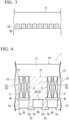
- the coil C can be formed in a mode called centralized winding shown in FIG. 4 .
- each coil C is formed by winding a wire around only one tooth 7T.
- An area surrounded by the back yoke 71 and the pair of adjacent tooth bodies 72 is the slot S for accommodating the coil C.
- the stator magnets 1B are arranged in a portion which is a portion (slot S) between the pair of adjacent tooth grasping portions 73 and on the radial inside of the coil C.
- Each of the stator magnets 1B is supported by the claw portions 74 not to fall off from the outside in the radial direction. That is, the claw portion 74 comes into contact with the inner peripheral surface of the stator magnet 1B.
- one stator magnet 1B is provided between the tooth grasping portions 73 of the same teeth 7T and between the tooth grasping portions 73 of the adjacent different teeth 7T.
- the stator magnet 1B is a permanent magnet such as a ferrite magnet or a neodymium magnet.
- the poles (magnetization direction) facing the inner peripheral side are different between the stator magnets 1B adjacent to each other. More specifically, these stator magnets 1B are arranged according to the Halbach magnet arrangement. As shown in FIG. 3 , in the Halbach magnet arrangement, the magnetization direction changes in order from one side in the circumferential direction to the other side in four clockwise directions.
- the arrow attached to the stator magnet 1B in FIG. 3 indicates the magnetization direction.
- This embodiment includes first slots S1 which each accommodates the coil C and the stator magnet 1B and second slots S2 which each accommodates only the stator magnet 1B.
- the first slots S1 and the second slots S2 are arranged in the circumferential direction. Since the dimension (width) of the first slot S1 in the circumferential direction is equal to that of the stator magnet 1B, the coil C and the stator magnet 1B can be provided inside the first slot S1. Accordingly, the molded coil C can be easily attached into the first slot S1. Additionally, it is also possible to adopt a configuration in which the plurality of second slots S2 are provided between the pair of first slots S1.
- the wedge W is provided between the coil C and the stator magnet 1B inside the first slot S.
- the wedge W is a member made of a material having a specific magnetic permeability of 1 or more and is provided for the purpose of insulating between the coil C and the stator magnet 1B and preventing the coil C from falling off.
- the specific magnetic permeability of the wedge W is preferably 10 or less.
- the first rotor 2 is provided inside the stator 1.
- the first rotor 2 includes a disk portion 5, a first rotor body 2H, and a plurality of pole pieces 2P.
- the disk portion 5 is formed in a disk shape centered on the axis Ac and is attached to the rotating shaft 6.
- the first rotor body 2H is attached to the outer peripheral side of the disk portion 5.
- the first rotor body 2H includes a cylindrical portion 21 which has a cylindrical shape centered on the axis Ac and a pair of support portions 22 which projects radially outward from the outer peripheral surface of the cylindrical portion 21.
- the cylindrical portion 21 is supported on the inner peripheral surface of the casing 4 through the bearing B (outer bearing B1) to be described later.
- the plurality of the pole pieces 2P are provided at the radially outer edges of the pair of support portions 22.
- the pole piece 2P is a magnetic material and generates a harmonic component of magnetic flux by interacting with the magnetic force of the stator magnet 1B and the rotor magnet 3B described later.
- the plurality of pole pieces 2P are provided at intervals in the circumferential direction of the axis Ac.
- a non-magnetic member is provided between the pole pieces 2P adjacent to each other to extend in the same direction as the pole pieces 2P.
- the second rotor 3 is provided between the pair of support portions 22 of the first rotor body 2H.
- the second rotor 3 includes a rotor core 3A and a plurality of rotor magnets 3B.
- the rotor core 3A is formed in an annular shape centered on the axis Ac.
- the inner peripheral surface of the rotor core 3A is rotatably supported by the outer peripheral surface of the cylindrical portion 21 of the first rotor body 2H through the bearing B (inner bearing B2).
- the plurality of rotor magnets 3B are arranged on the outer peripheral surface of the rotor core 3A in the circumferential direction. Each of the rotor magnet 3B faces outward in the radial direction with respect to the pole piece 2P.
- the magnetic geared rotary electric machine 100 when used as the generator, a rotational force (torque) around the axis Ac is applied to the rotating shaft 6. Accordingly, the first rotor 2 and the second rotor 3 rotate by the rotation of the rotating shaft 6. An induced electromotive force is generated in the coil C as the first rotor 2 and the second rotor 3 rotate. By taking out this electric power to the outside, the magnetic geared rotary electric machine 100 can be used as the generator.
- the tooth grasping portion 73 is configured to hold the stator magnet 1B on the radial inside of the coil C and on the radial inside of the tooth body 72, respectively.
- stator magnet 1B Since the stator magnet 1B is provided on the radial inside of the coil C, it is possible to increase the opening width of the slot S1 provided with the coil C. Therefore, it is possible to attach even the coil C made of a high voltage lead wire having a large diameter.
- the tooth body 72 having a small magnetic resistance exists as a relatively wide area on the radial outside of the stator magnet 1B. Accordingly, the tooth grasping portion 73 holding the stator magnet 1B can guide the magnetic flux wave component from the second rotor 3 to the tooth body 72 having a small magnetic resistance. As a result, it is possible to largely reduce the magnetic resistance of the teeth 7T as a whole with respect to the fundamental wave magnetic flux of the second rotor 3 and to effectively use the magnetic energy generated by the rotor magnet 3B of the second rotor 3.
- the claw portions 74 are provided to be widened from the tooth grasping portion 73, it is possible to reduce the magnetic resistance of the portion of the stator 1 facing the rotor magnet 3B.
- stator magnets 1B are arranged in a Halbach magnet arrangement. Accordingly, it is possible to strengthen a specific directional component of the magnetic field strength generated by the stator magnet 1B. Thus, it is possible to enhance the magnetic performance of the stator magnet 1B and to improve the torque of the magnetic geared rotary electric machine 100.
- the wedge W can prevent the coil C from falling off.
- the tooth grasping portion 73b may be formed so that the circumferential width dimension of the tooth grasping portion 73b is gradually increased from the radial outside to the radial inside.
- the profile of the teeth gasping portion 73b when the space (slot S) between the tooth grasping portions 73b and the cross-section orthogonal to the axis Ac of the stator magnet 1B are viewed from the direction of the axis Ac, is a trapezoidal shape (wedge shape) with the radial inside as the upper bottom.
- the tooth grasping portion 73b has a wedge shape, the claw portion 74 is not necessary. Therefore, it is possible to reduce the clearance between the stator magnet 1B and the pole piece 2P. Accordingly, it is possible to effectively use the energy of the magnet. Further, since the stator magnet 1B is fitted into the opening portion of the slot S1 in a wedge shape, the stator magnet can have a role as a support member of the coil C. Further, since the tooth grasping portion 73b has a higher strength than that of the claw portion 74, it is possible to more reliably hold the stator magnet 1B.
- FIG. 6 a configuration, which is outside the scope of the claimed invention, may be adopted in which another tooth grasping portion 75 protruding radially inward from the tooth body 72 is formed between the pair of tooth grasping portions 73 at both ends of the tooth body 72 in the circumferential direction. Then, the plurality of stator magnets 1B may be provided in the same teeth 7T to be held between the tooth grasping portions 73 and 75 of the same teeth 7T. A plurality of another tooth grasping portions 75 may be provided. Further, the same applies to the case of the wedge-shaped tooth grasping portion 73b.
- the present disclosure relates to a magnetic geared rotary electric machine.
Landscapes
- Engineering & Computer Science (AREA)
- Power Engineering (AREA)
- Iron Core Of Rotating Electric Machines (AREA)
- Permanent Field Magnets Of Synchronous Machinery (AREA)
- Dynamo-Electric Clutches, Dynamo-Electric Brakes (AREA)
Claims (5)
- Eine magnetisch übersetzte drehende elektrische Maschine (100), umfassend:ein Gehäuse (4);einen Stator, umfassend einen Stator-Kern (1A), der am Gehäuse (4) befestigt und ringförmig um eine Achse herum ausgebildet ist, eine Spule (C), die innerhalb einer Vielzahl von ersten Schlitzen (S1) des Stator-Kerns (1A) angeordnet ist, und eine Vielzahl von Stator-Magneten (1B), die innerhalb des Stator-Kerns (1A) in Abständen in Umfangsrichtung um die Achse angeordnet sind;einen ersten Rotor (2), der eine Vielzahl von Polstücken, die radial innerhalb des Stators in Abständen in Umfangsrichtung um die Achse angeordnet sind, umfasst;einen zweiten Rotor (3), der einen Rotor-Kern, der radial innerhalb des ersten Rotors angeordnet ist, und eine Vielzahl von Rotor-Magneten (3B), die im Rotor-Kern in Abständen in Umfangsrichtung angeordnet sind, umfasst;wobei der Stator-Kern (1A) ein Rückjoch (71), das die Achse umgibt, und eine Vielzahl von Zähnen, die auf dem Rückjoch in Abständen in Umfangsrichtung ausgebildet sind, umfasst,wobei jeder der Vielzahl von Zähnen (7T) einen Zahnkörper (72), der sich radial vom Rückjoch (71) nach innen erstreckt, und ein Paar Zahnfassungsabschnitte (73, 73b), die sich radial von den beiden Umfangsenden eines radial inneren Abschnitts des Zahnkörpers erstrecken, umfasst;wobei die Spule (C) innerhalb der ersten Schlitze (S1), die zwischen den Zahnkörpern benachbarter Zähne ausgebildet werden, angeordnet ist;wobei die Stator-Magnete (1B) innerhalb zweiter Schlitze (S2) angeordnet sind, wobei jeder zweite Schlitz (S2) zwischen dem Paar Zahnfassungsabschnitten (73, 73b) eines jeweiligen Zahns ausgebildet ist, und wobei die Stator-Magnete (1B) ferner innerhalb der ersten Schlitze (S1) zwischen den Zahnfassungsabschnitten (73, 73b) unterschiedlicher benachbarter Zähne angeordnet sind;wobei die Zahnfassungsabschnitte (73) eingerichtet sind, um die Stator-Magnete radial innerhalb der Spule (C) in den ersten Schlitzen (S1) und radial innerhalb des Zahnkörpers (72) innerhalb der zweiten Schlitze (S2) zu halten,beziehungsweise, wobei der Stator-Magnet (1B), der radial innerhalb der Spule (C) gehalten wird, und der Stator-Magnet (1B), der radial innerhalb des Zahnkörpers (72) gehalten wird, abwechselnd angeordnet sind.
- Die magnetisch übersetzte drehende elektrische Maschine nach Anspruch 1, weiterhin umfassend:
einen Krallenabschnitt (74), der an einem oberen Ende des Zahnfassungsabschnitts (73, 73b) derart ausgebildet ist, dass er sich in Umfangsrichtung erstreckt. - Die magnetisch übersetzte drehende elektrische Maschine nach Anspruch 1 oder 2, wobei der Zahnfassungsabschnitt (73, 73b) derart ausgebildet ist, dass sich eine Breite des Zahnfassungsabschnitts (73, 73b) in Umfangsrichtung von radial außen nach radial innen graduell vergrößert.
- Die magnetisch übersetzte drehende elektrische Maschine nach einem der Ansprüche 1 bis 3, wobei die Vielzahl von Stator-Magneten (1B) in einer Halbach-Magnet-Anordnung angeordnet ist.
- Die magnetisch übersetzte drehende elektrische Maschine nach einem der Ansprüche 1 bis 4, weiterhin umfassend:
einen Keil (W), der zwischen der Spule und dem Stator-Magneten (1B) angeordnet ist.
Applications Claiming Priority (2)
| Application Number | Priority Date | Filing Date | Title |
|---|---|---|---|
| JP2020010264A JP7384678B2 (ja) | 2020-01-24 | 2020-01-24 | 磁気ギアード回転電機 |
| PCT/JP2021/000081 WO2021149473A1 (ja) | 2020-01-24 | 2021-01-05 | 磁気ギアード回転電機 |
Publications (3)
| Publication Number | Publication Date |
|---|---|
| EP4080743A1 EP4080743A1 (de) | 2022-10-26 |
| EP4080743A4 EP4080743A4 (de) | 2023-01-25 |
| EP4080743B1 true EP4080743B1 (de) | 2025-03-05 |
Family
ID=76993348
Family Applications (1)
| Application Number | Title | Priority Date | Filing Date |
|---|---|---|---|
| EP21743641.9A Active EP4080743B1 (de) | 2020-01-24 | 2021-01-05 | Elektrische drehmaschine mit magnetgetriebe |
Country Status (5)
| Country | Link |
|---|---|
| US (1) | US20230046567A1 (de) |
| EP (1) | EP4080743B1 (de) |
| JP (1) | JP7384678B2 (de) |
| CN (1) | CN114946111A (de) |
| WO (1) | WO2021149473A1 (de) |
Families Citing this family (6)
| Publication number | Priority date | Publication date | Assignee | Title |
|---|---|---|---|---|
| CN114902532B (zh) * | 2020-01-14 | 2025-07-29 | 雅马哈发动机株式会社 | 轴向间隙型马达 |
| JP7090828B1 (ja) * | 2021-11-18 | 2022-06-24 | 三菱電機株式会社 | 永久磁石式回転電機 |
| JP7749488B2 (ja) * | 2022-02-16 | 2025-10-06 | 三菱重工業株式会社 | 磁気ギアード電気機械 |
| JP7748069B2 (ja) * | 2022-10-28 | 2025-10-02 | 三菱重工業株式会社 | 磁気ギア、および、磁気ギアード電気機械 |
| JP2024148659A (ja) * | 2023-04-06 | 2024-10-18 | 株式会社ミツバ | モータ装置 |
| JPWO2024241363A1 (de) * | 2023-05-19 | 2024-11-28 |
Family Cites Families (14)
| Publication number | Priority date | Publication date | Assignee | Title |
|---|---|---|---|---|
| FR2563059B1 (fr) * | 1984-04-13 | 1988-04-15 | Cem Comp Electro Mec | Machine electrodynamique vernier |
| US4761580A (en) * | 1987-06-17 | 1988-08-02 | Magnetek, Inc. | Magnetic top wedge |
| CN102545510A (zh) * | 2010-12-15 | 2012-07-04 | 江建中 | 新型集中绕组外定子的磁性齿轮复合电机 |
| JP6093592B2 (ja) * | 2013-02-22 | 2017-03-08 | 株式会社Ihi | 磁気波動歯車装置 |
| US9438096B2 (en) * | 2013-07-30 | 2016-09-06 | Praxair Technology, Inc. | Electric motor and magnetic gear |
| CN103795159B (zh) * | 2014-01-03 | 2016-02-10 | 东南大学 | 定转子双永磁型游标电机 |
| JP2016032385A (ja) * | 2014-07-30 | 2016-03-07 | ダイキン工業株式会社 | 電動機 |
| JP6403329B2 (ja) * | 2015-01-20 | 2018-10-10 | 株式会社Ihi | 磁気波動歯車装置 |
| CN104917310A (zh) * | 2015-06-29 | 2015-09-16 | 中国船舶重工集团公司第七一二研究所 | 一种低速磁阻电动机及其制作方法 |
| GB2549448A (en) * | 2016-01-13 | 2017-10-25 | Magnomatics Ltd | A magnetically geared apparatus |
| CN107612281B (zh) * | 2017-10-16 | 2023-12-22 | 三峡大学 | 一种改进Halbach型磁性齿轮装置 |
| KR102541176B1 (ko) * | 2017-12-19 | 2023-06-08 | 엘지전자 주식회사 | 모터 |
| JP6952653B2 (ja) | 2018-07-11 | 2021-10-20 | Kddi株式会社 | 端末装置の送信電力を制御する基地局装置、その制御方法、及びプログラム |
| CN108900055A (zh) * | 2018-09-06 | 2018-11-27 | 无锡力必特自动化设备有限公司 | 一种非均匀排列的裂齿定转子永磁游标电机 |
-
2020
- 2020-01-24 JP JP2020010264A patent/JP7384678B2/ja active Active
-
2021
- 2021-01-05 CN CN202180009582.8A patent/CN114946111A/zh active Pending
- 2021-01-05 EP EP21743641.9A patent/EP4080743B1/de active Active
- 2021-01-05 US US17/794,049 patent/US20230046567A1/en not_active Abandoned
- 2021-01-05 WO PCT/JP2021/000081 patent/WO2021149473A1/ja not_active Ceased
Also Published As
| Publication number | Publication date |
|---|---|
| JP7384678B2 (ja) | 2023-11-21 |
| JP2021118611A (ja) | 2021-08-10 |
| EP4080743A1 (de) | 2022-10-26 |
| EP4080743A4 (de) | 2023-01-25 |
| WO2021149473A1 (ja) | 2021-07-29 |
| CN114946111A (zh) | 2022-08-26 |
| US20230046567A1 (en) | 2023-02-16 |
Similar Documents
| Publication | Publication Date | Title |
|---|---|---|
| EP4080743A1 (de) | Elektrische drehmaschine mit magnetgetriebe | |
| JP5682600B2 (ja) | 回転電機のロータ | |
| EP2845295B1 (de) | Rotor für rotierende elektrische vorrichtung | |
| US20070018520A1 (en) | Motor/generator to reduce cogging torque | |
| US20110163641A1 (en) | Permanent-magnet synchronous motor | |
| JP6048191B2 (ja) | マルチギャップ型回転電機 | |
| EP3661034B1 (de) | Elektrische drehmaschine | |
| US10447096B2 (en) | Permanent-magnet-type rotating electrical machine | |
| JP7685829B2 (ja) | 電動機 | |
| US12057740B2 (en) | Rotary electric machine | |
| EP4084289A1 (de) | Magnetische dynamo-elektrische getriebemaschine und verfahren zum herstellen eines stators | |
| JP5195450B2 (ja) | スロットレスモータ | |
| EP4096062A1 (de) | Stator und rotierende elektrische maschine damit | |
| JPH1198728A (ja) | 永久磁石回転電機 | |
| JP4491211B2 (ja) | 永久磁石式回転電機 | |
| KR20090007370U (ko) | 자속 집중형 전동기 | |
| KR20200014040A (ko) | 토크리플 감소를 위한 노치구조의 전동기 | |
| JP2018148675A (ja) | 回転電機のステータ | |
| WO2011036723A1 (ja) | 同期発電機 | |
| JP2012060709A (ja) | 永久磁石型モータ | |
| KR102120361B1 (ko) | 길이가 다른 도체바를 구비하는 회전자 및 그를 포함하는 동기형 모터 | |
| JP2022156718A (ja) | 電動機用ロータ、及び電動機 | |
| JPWO2020208692A1 (ja) | 電動機 | |
| JP6484009B2 (ja) | モータ | |
| JP5924913B2 (ja) | 発電機 |
Legal Events
| Date | Code | Title | Description |
|---|---|---|---|
| STAA | Information on the status of an ep patent application or granted ep patent |
Free format text: STATUS: THE INTERNATIONAL PUBLICATION HAS BEEN MADE |
|
| PUAI | Public reference made under article 153(3) epc to a published international application that has entered the european phase |
Free format text: ORIGINAL CODE: 0009012 |
|
| STAA | Information on the status of an ep patent application or granted ep patent |
Free format text: STATUS: REQUEST FOR EXAMINATION WAS MADE |
|
| 17P | Request for examination filed |
Effective date: 20220718 |
|
| AK | Designated contracting states |
Kind code of ref document: A1 Designated state(s): AL AT BE BG CH CY CZ DE DK EE ES FI FR GB GR HR HU IE IS IT LI LT LU LV MC MK MT NL NO PL PT RO RS SE SI SK SM TR |
|
| A4 | Supplementary search report drawn up and despatched |
Effective date: 20230103 |
|
| RIC1 | Information provided on ipc code assigned before grant |
Ipc: H02K 21/44 20060101ALI20221221BHEP Ipc: H02K 7/11 20060101ALI20221221BHEP Ipc: H02K 1/17 20060101ALI20221221BHEP Ipc: H02K 1/12 20060101ALI20221221BHEP Ipc: H02K 49/10 20060101ALI20221221BHEP Ipc: H02K 16/02 20060101AFI20221221BHEP |
|
| DAV | Request for validation of the european patent (deleted) | ||
| DAX | Request for extension of the european patent (deleted) | ||
| STAA | Information on the status of an ep patent application or granted ep patent |
Free format text: STATUS: EXAMINATION IS IN PROGRESS |
|
| 17Q | First examination report despatched |
Effective date: 20240226 |
|
| GRAP | Despatch of communication of intention to grant a patent |
Free format text: ORIGINAL CODE: EPIDOSNIGR1 |
|
| STAA | Information on the status of an ep patent application or granted ep patent |
Free format text: STATUS: GRANT OF PATENT IS INTENDED |
|
| INTG | Intention to grant announced |
Effective date: 20240909 |
|
| GRAS | Grant fee paid |
Free format text: ORIGINAL CODE: EPIDOSNIGR3 |
|
| GRAA | (expected) grant |
Free format text: ORIGINAL CODE: 0009210 |
|
| STAA | Information on the status of an ep patent application or granted ep patent |
Free format text: STATUS: THE PATENT HAS BEEN GRANTED |
|
| AK | Designated contracting states |
Kind code of ref document: B1 Designated state(s): AL AT BE BG CH CY CZ DE DK EE ES FI FR GB GR HR HU IE IS IT LI LT LU LV MC MK MT NL NO PL PT RO RS SE SI SK SM TR |
|
| REG | Reference to a national code |
Ref country code: GB Ref legal event code: FG4D |
|
| REG | Reference to a national code |
Ref country code: CH Ref legal event code: EP |
|
| REG | Reference to a national code |
Ref country code: IE Ref legal event code: FG4D |
|
| REG | Reference to a national code |
Ref country code: DE Ref legal event code: R096 Ref document number: 602021027182 Country of ref document: DE |
|
| PG25 | Lapsed in a contracting state [announced via postgrant information from national office to epo] |
Ref country code: RS Free format text: LAPSE BECAUSE OF FAILURE TO SUBMIT A TRANSLATION OF THE DESCRIPTION OR TO PAY THE FEE WITHIN THE PRESCRIBED TIME-LIMIT Effective date: 20250605 |
|
| PG25 | Lapsed in a contracting state [announced via postgrant information from national office to epo] |
Ref country code: FI Free format text: LAPSE BECAUSE OF FAILURE TO SUBMIT A TRANSLATION OF THE DESCRIPTION OR TO PAY THE FEE WITHIN THE PRESCRIBED TIME-LIMIT Effective date: 20250305 |
|
| REG | Reference to a national code |
Ref country code: NL Ref legal event code: MP Effective date: 20250305 |
|
| PG25 | Lapsed in a contracting state [announced via postgrant information from national office to epo] |
Ref country code: ES Free format text: LAPSE BECAUSE OF FAILURE TO SUBMIT A TRANSLATION OF THE DESCRIPTION OR TO PAY THE FEE WITHIN THE PRESCRIBED TIME-LIMIT Effective date: 20250305 |
|
| REG | Reference to a national code |
Ref country code: LT Ref legal event code: MG9D |
|
| PG25 | Lapsed in a contracting state [announced via postgrant information from national office to epo] |
Ref country code: NO Free format text: LAPSE BECAUSE OF FAILURE TO SUBMIT A TRANSLATION OF THE DESCRIPTION OR TO PAY THE FEE WITHIN THE PRESCRIBED TIME-LIMIT Effective date: 20250605 |
|
| PG25 | Lapsed in a contracting state [announced via postgrant information from national office to epo] |
Ref country code: HR Free format text: LAPSE BECAUSE OF FAILURE TO SUBMIT A TRANSLATION OF THE DESCRIPTION OR TO PAY THE FEE WITHIN THE PRESCRIBED TIME-LIMIT Effective date: 20250305 |
|
| PG25 | Lapsed in a contracting state [announced via postgrant information from national office to epo] |
Ref country code: LV Free format text: LAPSE BECAUSE OF FAILURE TO SUBMIT A TRANSLATION OF THE DESCRIPTION OR TO PAY THE FEE WITHIN THE PRESCRIBED TIME-LIMIT Effective date: 20250305 |
|
| PG25 | Lapsed in a contracting state [announced via postgrant information from national office to epo] |
Ref country code: GR Free format text: LAPSE BECAUSE OF FAILURE TO SUBMIT A TRANSLATION OF THE DESCRIPTION OR TO PAY THE FEE WITHIN THE PRESCRIBED TIME-LIMIT Effective date: 20250606 Ref country code: BG Free format text: LAPSE BECAUSE OF FAILURE TO SUBMIT A TRANSLATION OF THE DESCRIPTION OR TO PAY THE FEE WITHIN THE PRESCRIBED TIME-LIMIT Effective date: 20250305 |
|
| REG | Reference to a national code |
Ref country code: AT Ref legal event code: MK05 Ref document number: 1773873 Country of ref document: AT Kind code of ref document: T Effective date: 20250305 |
|
| PG25 | Lapsed in a contracting state [announced via postgrant information from national office to epo] |
Ref country code: NL Free format text: LAPSE BECAUSE OF FAILURE TO SUBMIT A TRANSLATION OF THE DESCRIPTION OR TO PAY THE FEE WITHIN THE PRESCRIBED TIME-LIMIT Effective date: 20250305 |
|
| PG25 | Lapsed in a contracting state [announced via postgrant information from national office to epo] |
Ref country code: SE Free format text: LAPSE BECAUSE OF FAILURE TO SUBMIT A TRANSLATION OF THE DESCRIPTION OR TO PAY THE FEE WITHIN THE PRESCRIBED TIME-LIMIT Effective date: 20250305 |
|
| PG25 | Lapsed in a contracting state [announced via postgrant information from national office to epo] |
Ref country code: SM Free format text: LAPSE BECAUSE OF FAILURE TO SUBMIT A TRANSLATION OF THE DESCRIPTION OR TO PAY THE FEE WITHIN THE PRESCRIBED TIME-LIMIT Effective date: 20250305 |
|
| PG25 | Lapsed in a contracting state [announced via postgrant information from national office to epo] |
Ref country code: PT Free format text: LAPSE BECAUSE OF FAILURE TO SUBMIT A TRANSLATION OF THE DESCRIPTION OR TO PAY THE FEE WITHIN THE PRESCRIBED TIME-LIMIT Effective date: 20250707 |
|
| PG25 | Lapsed in a contracting state [announced via postgrant information from national office to epo] |
Ref country code: PL Free format text: LAPSE BECAUSE OF FAILURE TO SUBMIT A TRANSLATION OF THE DESCRIPTION OR TO PAY THE FEE WITHIN THE PRESCRIBED TIME-LIMIT Effective date: 20250305 Ref country code: IT Free format text: LAPSE BECAUSE OF FAILURE TO SUBMIT A TRANSLATION OF THE DESCRIPTION OR TO PAY THE FEE WITHIN THE PRESCRIBED TIME-LIMIT Effective date: 20250305 |
|
| PG25 | Lapsed in a contracting state [announced via postgrant information from national office to epo] |
Ref country code: AT Free format text: LAPSE BECAUSE OF FAILURE TO SUBMIT A TRANSLATION OF THE DESCRIPTION OR TO PAY THE FEE WITHIN THE PRESCRIBED TIME-LIMIT Effective date: 20250305 |
|
| PG25 | Lapsed in a contracting state [announced via postgrant information from national office to epo] |
Ref country code: CZ Free format text: LAPSE BECAUSE OF FAILURE TO SUBMIT A TRANSLATION OF THE DESCRIPTION OR TO PAY THE FEE WITHIN THE PRESCRIBED TIME-LIMIT Effective date: 20250305 Ref country code: EE Free format text: LAPSE BECAUSE OF FAILURE TO SUBMIT A TRANSLATION OF THE DESCRIPTION OR TO PAY THE FEE WITHIN THE PRESCRIBED TIME-LIMIT Effective date: 20250305 |
|
| PG25 | Lapsed in a contracting state [announced via postgrant information from national office to epo] |
Ref country code: RO Free format text: LAPSE BECAUSE OF FAILURE TO SUBMIT A TRANSLATION OF THE DESCRIPTION OR TO PAY THE FEE WITHIN THE PRESCRIBED TIME-LIMIT Effective date: 20250305 |
|
| PG25 | Lapsed in a contracting state [announced via postgrant information from national office to epo] |
Ref country code: SK Free format text: LAPSE BECAUSE OF FAILURE TO SUBMIT A TRANSLATION OF THE DESCRIPTION OR TO PAY THE FEE WITHIN THE PRESCRIBED TIME-LIMIT Effective date: 20250305 |
|
| PG25 | Lapsed in a contracting state [announced via postgrant information from national office to epo] |
Ref country code: IS Free format text: LAPSE BECAUSE OF FAILURE TO SUBMIT A TRANSLATION OF THE DESCRIPTION OR TO PAY THE FEE WITHIN THE PRESCRIBED TIME-LIMIT Effective date: 20250705 |
|
| REG | Reference to a national code |
Ref country code: DE Ref legal event code: R097 Ref document number: 602021027182 Country of ref document: DE |
|
| PGFP | Annual fee paid to national office [announced via postgrant information from national office to epo] |
Ref country code: GB Payment date: 20251127 Year of fee payment: 6 |
|
| PLBE | No opposition filed within time limit |
Free format text: ORIGINAL CODE: 0009261 |
|
| STAA | Information on the status of an ep patent application or granted ep patent |
Free format text: STATUS: NO OPPOSITION FILED WITHIN TIME LIMIT |
|
| PG25 | Lapsed in a contracting state [announced via postgrant information from national office to epo] |
Ref country code: DK Free format text: LAPSE BECAUSE OF FAILURE TO SUBMIT A TRANSLATION OF THE DESCRIPTION OR TO PAY THE FEE WITHIN THE PRESCRIBED TIME-LIMIT Effective date: 20250305 |
|
| REG | Reference to a national code |
Ref country code: CH Ref legal event code: L10 Free format text: ST27 STATUS EVENT CODE: U-0-0-L10-L00 (AS PROVIDED BY THE NATIONAL OFFICE) Effective date: 20260114 |
|
| 26N | No opposition filed |
Effective date: 20251208 |