EP2949870B1 - Verstellrotor mit entfernten gegengewichten - Google Patents
Verstellrotor mit entfernten gegengewichten Download PDFInfo
- Publication number
- EP2949870B1 EP2949870B1 EP15168754.8A EP15168754A EP2949870B1 EP 2949870 B1 EP2949870 B1 EP 2949870B1 EP 15168754 A EP15168754 A EP 15168754A EP 2949870 B1 EP2949870 B1 EP 2949870B1
- Authority
- EP
- European Patent Office
- Prior art keywords
- blades
- unison ring
- counterweights
- counterweight
- rotor structure
- Prior art date
- Legal status (The legal status is an assumption and is not a legal conclusion. Google has not performed a legal analysis and makes no representation as to the accuracy of the status listed.)
- Not-in-force
Links
Images


Classifications
-
- F—MECHANICAL ENGINEERING; LIGHTING; HEATING; WEAPONS; BLASTING
- F01—MACHINES OR ENGINES IN GENERAL; ENGINE PLANTS IN GENERAL; STEAM ENGINES
- F01D—NON-POSITIVE DISPLACEMENT MACHINES OR ENGINES, e.g. STEAM TURBINES
- F01D7/00—Rotors with blades adjustable in operation; Control thereof
- F01D7/02—Rotors with blades adjustable in operation; Control thereof having adjustment responsive to speed
-
- F—MECHANICAL ENGINEERING; LIGHTING; HEATING; WEAPONS; BLASTING
- F01—MACHINES OR ENGINES IN GENERAL; ENGINE PLANTS IN GENERAL; STEAM ENGINES
- F01D—NON-POSITIVE DISPLACEMENT MACHINES OR ENGINES, e.g. STEAM TURBINES
- F01D21/00—Shutting-down of machines or engines, e.g. in emergency; Regulating, controlling, or safety means not otherwise provided for
- F01D21/04—Shutting-down of machines or engines, e.g. in emergency; Regulating, controlling, or safety means not otherwise provided for responsive to undesired position of rotor relative to stator or to breaking-off of a part of the rotor, e.g. indicating such position
- F01D21/08—Restoring position
-
- F—MECHANICAL ENGINEERING; LIGHTING; HEATING; WEAPONS; BLASTING
- F01—MACHINES OR ENGINES IN GENERAL; ENGINE PLANTS IN GENERAL; STEAM ENGINES
- F01D—NON-POSITIVE DISPLACEMENT MACHINES OR ENGINES, e.g. STEAM TURBINES
- F01D5/00—Blades; Blade-carrying members; Heating, heat-insulating, cooling or antivibration means on the blades or the members
- F01D5/02—Blade-carrying members, e.g. rotors
-
- F—MECHANICAL ENGINEERING; LIGHTING; HEATING; WEAPONS; BLASTING
- F02—COMBUSTION ENGINES; HOT-GAS OR COMBUSTION-PRODUCT ENGINE PLANTS
- F02C—GAS-TURBINE PLANTS; AIR INTAKES FOR JET-PROPULSION PLANTS; CONTROLLING FUEL SUPPLY IN AIR-BREATHING JET-PROPULSION PLANTS
- F02C3/00—Gas-turbine plants characterised by the use of combustion products as the working fluid
- F02C3/04—Gas-turbine plants characterised by the use of combustion products as the working fluid having a turbine driving a compressor
-
- F—MECHANICAL ENGINEERING; LIGHTING; HEATING; WEAPONS; BLASTING
- F05—INDEXING SCHEMES RELATING TO ENGINES OR PUMPS IN VARIOUS SUBCLASSES OF CLASSES F01-F04
- F05D—INDEXING SCHEME FOR ASPECTS RELATING TO NON-POSITIVE-DISPLACEMENT MACHINES OR ENGINES, GAS-TURBINES OR JET-PROPULSION PLANTS
- F05D2220/00—Application
- F05D2220/30—Application in turbines
- F05D2220/32—Application in turbines in gas turbines
-
- F—MECHANICAL ENGINEERING; LIGHTING; HEATING; WEAPONS; BLASTING
- F05—INDEXING SCHEMES RELATING TO ENGINES OR PUMPS IN VARIOUS SUBCLASSES OF CLASSES F01-F04
- F05D—INDEXING SCHEME FOR ASPECTS RELATING TO NON-POSITIVE-DISPLACEMENT MACHINES OR ENGINES, GAS-TURBINES OR JET-PROPULSION PLANTS
- F05D2220/00—Application
- F05D2220/30—Application in turbines
- F05D2220/36—Application in turbines specially adapted for the fan of turbofan engines
-
- F—MECHANICAL ENGINEERING; LIGHTING; HEATING; WEAPONS; BLASTING
- F05—INDEXING SCHEMES RELATING TO ENGINES OR PUMPS IN VARIOUS SUBCLASSES OF CLASSES F01-F04
- F05D—INDEXING SCHEME FOR ASPECTS RELATING TO NON-POSITIVE-DISPLACEMENT MACHINES OR ENGINES, GAS-TURBINES OR JET-PROPULSION PLANTS
- F05D2240/00—Components
- F05D2240/20—Rotors
- F05D2240/30—Characteristics of rotor blades, i.e. of any element transforming dynamic fluid energy to or from rotational energy and being attached to a rotor
-
- F—MECHANICAL ENGINEERING; LIGHTING; HEATING; WEAPONS; BLASTING
- F05—INDEXING SCHEMES RELATING TO ENGINES OR PUMPS IN VARIOUS SUBCLASSES OF CLASSES F01-F04
- F05D—INDEXING SCHEME FOR ASPECTS RELATING TO NON-POSITIVE-DISPLACEMENT MACHINES OR ENGINES, GAS-TURBINES OR JET-PROPULSION PLANTS
- F05D2260/00—Function
- F05D2260/50—Kinematic linkage, i.e. transmission of position
- F05D2260/53—Kinematic linkage, i.e. transmission of position using gears
-
- F—MECHANICAL ENGINEERING; LIGHTING; HEATING; WEAPONS; BLASTING
- F05—INDEXING SCHEMES RELATING TO ENGINES OR PUMPS IN VARIOUS SUBCLASSES OF CLASSES F01-F04
- F05D—INDEXING SCHEME FOR ASPECTS RELATING TO NON-POSITIVE-DISPLACEMENT MACHINES OR ENGINES, GAS-TURBINES OR JET-PROPULSION PLANTS
- F05D2260/00—Function
- F05D2260/70—Adjusting of angle of incidence or attack of rotating blades
- F05D2260/77—Adjusting of angle of incidence or attack of rotating blades the adjusting mechanism driven or triggered by centrifugal forces
-
- F—MECHANICAL ENGINEERING; LIGHTING; HEATING; WEAPONS; BLASTING
- F05—INDEXING SCHEMES RELATING TO ENGINES OR PUMPS IN VARIOUS SUBCLASSES OF CLASSES F01-F04
- F05D—INDEXING SCHEME FOR ASPECTS RELATING TO NON-POSITIVE-DISPLACEMENT MACHINES OR ENGINES, GAS-TURBINES OR JET-PROPULSION PLANTS
- F05D2260/00—Function
- F05D2260/70—Adjusting of angle of incidence or attack of rotating blades
- F05D2260/79—Bearing, support or actuation arrangements therefor
-
- F—MECHANICAL ENGINEERING; LIGHTING; HEATING; WEAPONS; BLASTING
- F05—INDEXING SCHEMES RELATING TO ENGINES OR PUMPS IN VARIOUS SUBCLASSES OF CLASSES F01-F04
- F05D—INDEXING SCHEME FOR ASPECTS RELATING TO NON-POSITIVE-DISPLACEMENT MACHINES OR ENGINES, GAS-TURBINES OR JET-PROPULSION PLANTS
- F05D2270/00—Control
- F05D2270/01—Purpose of the control system
- F05D2270/02—Purpose of the control system to control rotational speed (n)
- F05D2270/021—Purpose of the control system to control rotational speed (n) to prevent overspeed
-
- F—MECHANICAL ENGINEERING; LIGHTING; HEATING; WEAPONS; BLASTING
- F05—INDEXING SCHEMES RELATING TO ENGINES OR PUMPS IN VARIOUS SUBCLASSES OF CLASSES F01-F04
- F05D—INDEXING SCHEME FOR ASPECTS RELATING TO NON-POSITIVE-DISPLACEMENT MACHINES OR ENGINES, GAS-TURBINES OR JET-PROPULSION PLANTS
- F05D2270/00—Control
- F05D2270/01—Purpose of the control system
- F05D2270/09—Purpose of the control system to cope with emergencies
-
- F—MECHANICAL ENGINEERING; LIGHTING; HEATING; WEAPONS; BLASTING
- F05—INDEXING SCHEMES RELATING TO ENGINES OR PUMPS IN VARIOUS SUBCLASSES OF CLASSES F01-F04
- F05D—INDEXING SCHEME FOR ASPECTS RELATING TO NON-POSITIVE-DISPLACEMENT MACHINES OR ENGINES, GAS-TURBINES OR JET-PROPULSION PLANTS
- F05D2270/00—Control
- F05D2270/50—Control logic embodiments
- F05D2270/58—Control logic embodiments by mechanical means, e.g. levers, gears or cams
-
- Y—GENERAL TAGGING OF NEW TECHNOLOGICAL DEVELOPMENTS; GENERAL TAGGING OF CROSS-SECTIONAL TECHNOLOGIES SPANNING OVER SEVERAL SECTIONS OF THE IPC; TECHNICAL SUBJECTS COVERED BY FORMER USPC CROSS-REFERENCE ART COLLECTIONS [XRACs] AND DIGESTS
- Y02—TECHNOLOGIES OR APPLICATIONS FOR MITIGATION OR ADAPTATION AGAINST CLIMATE CHANGE
- Y02T—CLIMATE CHANGE MITIGATION TECHNOLOGIES RELATED TO TRANSPORTATION
- Y02T50/00—Aeronautics or air transport
- Y02T50/60—Efficient propulsion technologies, e.g. for aircraft
Definitions
- This invention relates generally to variable-pitch rotors and more particularly to control mechanisms for such rotors.
- Aircraft powerplants are typically used to drive thrust-generating airfoil elements such as propellers or fan blades. It is known to vary the angle of incidence (i.e. "pitch angle") of the airfoil elements relative to the rotating hub carrying them, in order to provide the maximum possible propulsive efficiency at various flight conditions.
- a common method of pitch control employs a hydraulic actuator which changes the blade pitch angle in response to pressurized fluid flow.
- the actuator may move the blade through pitch angles from “coarse” to “fine” and may also provide pitch angles suitable for ground operation.
- a typical prior art variable-pitch rotor includes a mechanical pitch lock which limits the blade pitch angle in the case of actuator failure. Pitch locks can be complicated and themselves subject to failure.
- variable-pitch rotors with counterweights.
- the counterweights provide a countervailing force that drives the blades to a safe pitch angle in case of actuator failure.
- these are typically mounted to the individual blades and therefore limit design flexibility.
- GB 2218747 discloses a pitch feathering system for a propeller blade that utilizes a counter-weight linked to the blade.
- the counter-weight is constrained to move, when effecting a pitch change, only in a radial plane and about an axis which rotates about the propeller axis.
- variable pitch blades are linked by a unison ring and a plurality of counter-weights are linked to the unison ring to change pitch via the unison ring under the action of centrifugal force.
- counter-weights pivot about axes tangential to a circle about the axis of rotation of the propeller, gears transmitting pitch change movement to the blade.
- FR 2964942 discloses a device having a vane attached to a retaining ring by a support pivot, where the vane is rotated around an axis of the pivot.
- a first drive unit is fixed on a root of the vane and a second drive unit is carried by the retaining ring, where the drive units are conical pinions.
- the second drive unit cooperates with the first drive unit to turn the support pivot in response to control of a regulating system that regulates pitch of the propeller.
- US 2012/328436 discloses a ram air turbine generator governor including a hub carrying multiple turbine blades.
- a counter-weight is coupled to at least one turbine blade and is configured to provide an input to the turbine blade in response to a centrifugal force to move the turbine blade from a first pitch position to a second pitch position.
- the pitch control mechanism provides a pitch control mechanism having counterweights which are mounted remotely from the blades and which are mechanically interconnected to the blades.
- the pitch control mechanism allows the design of the counterweights (including for example, their number, size, and position) to be determined independently from the design of the blades and trunnions.
- a pitch control mechanism includes: a rotor structure configured for rotation about a longitudinal axis; a row of blades carried by the rotor structure, each blade having an airfoil and a trunnion mounted for pivoting movement relative to the rotor structure, about a trunnion axis which is perpendicular to the longitudinal axis; a unison ring interconnecting the blades; an actuator connected to the unison ring and the rotor structure, operable to move the unison ring relative to the rotor structure; at least one moveable counterweight carried by the rotor structure, remote from the blades; and an interconnection between the blades and the counterweight, such that movement of the counterweight causes a change in the pitch angle of the blades.
- the actuator is configured to produce linear movement between the rotor structure and the unison ring.
- the trunnions are connected to the counterweights by a geared connection and / or the counterweights are connected to the actuator by a geared connection.
- the unison ring and counterweights are interconnected by gears.
- the rotor structure carries an array of counterweight assemblies each including: a pinion shaft, a pinion gear, and a counterweight with an offset mass.
- all of the pinion gears are engaged with a ring gear that is part of the unison ring, and with a sun gear that is stationary relative to the rotor structure.
- the pinion gears are meshed with a ring gear that is part of the unison ring.
- each counterweight includes a hollow shell with a slug of high-density material inside.
- each trunnion is connected to the unison ring with a yoke.
- each yoke includes a pin that engages a pivot hole in a slider that is mounted for longitudinal sliding movement in the unison ring.
- the trunnions are connected to the unison ring by a geared connection.
- the counterweights are mounted to a pinion shaft that rotates about a radial axis.
- the trunnions are connected to the unison ring by a geared connection.
- the pitch angle is variable between a fine pitch angle and a coarse pitch angle
- the counterweights are configured to drive the pitch angle towards the coarse pitch angle
- a gas turbine engine includes: turbomachinery core operable to produce a core gas flow; a low pressure turbine positioned downstream of the turbomachinery core; an inner shaft coupled to the low pressure turbine; and the pitch control mechanism described above, wherein the rotor structure is coupled to the inner shaft.
- Figure 1 depicts a gas turbine engine 10.
- the engine 10 has a longitudinal axis 11 and includes a fan 12 and a low pressure turbine (“LPT") 16 collectively referred to as a "low pressure system”.
- the LPT 16 drives the fan 12 through an inner shaft 18, also referred to as an "LP shaft”.
- the engine 10 also includes a high pressure compressor (“HPC”) 20, a combustor 22, and a high pressure turbine (“HPT”) 24, collectively referred to as a "gas generator” or "core”.
- HPT 24 drives the HPC 20 through an outer shaft 26, also referred to as an "HP shaft".
- the high and low pressure systems are operable in a known manner to generate a primary or core flow as well as a fan flow or bypass flow. While the illustrated engine 10 is a high-bypass turbofan engine, the principles described herein are equally applicable to any other type of engine requiring variable-pitch blades, including turboprop engines and piston aircraft engines.
- the fan 12 includes an annular array of blades 28.
- Each blade 28 includes an airfoil 30 mounted to that it can pivot about a trunnion axis "T" which extends radially from the longitudinal axis 11. Pivoting motion of the blade 28 about this axis changes its pitch angle ⁇ .
- the pitch angle ⁇ is defined as the angle between a zero-lift line of the airfoil 30 and a plane perpendicular to the longitudinal axis 11.
- a blade is shown at an intermediate pitch angle at "I"
- a blade is shown at a maximum high (or coarse) pitch angle at "II", corresponding to a feathered condition, and a low (or fine) pitch angle at "III”.
- the term “axial” or “longitudinal” refers to a direction parallel to an axis of rotation of a gas turbine engine
- radial refers to a direction perpendicular to the axial direction
- tangential or “circumferential” refers to a direction mutually perpendicular to the axial and tangential directions.
- forward or “front” refer to a location relatively upstream in an air flow passing through or around a component
- the terms “aft” or “rear” refer to a location relatively downstream in an air flow passing through or around a component. The direction of this flow is shown by the arrow “F” in FIG. 1 .
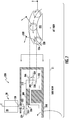
- FIGS. 3 and 4 illustrate pictorially an exemplary pitch control mechanism 100 constructed according to an aspect of the present invention
- FIG. 5 is a functional diagram showing the pitch control mechanism 100 in half-section.
- the pitch control mechanism 100 is one of several mechanisms that may be used to control the pitch angle ⁇ of the blades 28 shown in FIG. 1 .
- the pitch control mechanism 100 includes a centrally-mounted rotor shaft 102 which rotates about the longitudinal axis 11. In operation it would be coupled to and rotated by the engine 10, for example by the inner shaft 18 shown in FIG. 1 .
- a drum 104 surrounds the rotor shaft 102 and is functionally coupled to the rotor shaft by an actuator 106.
- the actuator 106 is shown schematically in FIGS. 3 and 4 .
- the actuator 106 may be any mechanism which is effective to selectively rotate the drum 104 about the longitudinal axis 11, and thereby change the relative angular orientation of the drum 104 and the rotor shaft 102.
- Known types of actuators include electrical, mechanical, and hydraulic devices.
- the actuator 106 may operate to provide rotary motion directly, or a linear actuator may be used with an appropriate mechanism to covert its motion to a rotary output, so long as the ultimate movement of the drum 104 is rotary.
- a plurality of axially-oriented slots 114 are formed around the periphery of the unison ring 108, adjacent the forward end 110.
- a slider 116 is disposed in each slot 114 and is free to move longitudinally forward or aft therein.
- Each slider 116 has a pivot hole 118 passing therethrough.
- Blades 28 are arrayed around the unison ring 108.
- the airfoil 30 of each blade 28 is attached to a trunnion 120 carried in suitable trunnion bearings 122, so that the blade 28 can pivot about the trunnion axis "T" as shown in FIG. 1 .
- An inner end of each trunnion 120 is connected to the aft end of a yoke 124.
- the forward end of each yoke 124 includes a pin 126 that extends radially inward and passes through the pivot hole 118 in one of the sliders 116.
- rotary motion of the unison ring 108 causes a simultaneous change in the pitch angle ⁇ of all the blades 28.
- a carrier 128 shaped like a shallow cylinder with a forward disk 130 and a peripheral wall 132 is disposed aft of the unison ring 108, and is mounted for rotation in unison with the rotor shaft 102.
- the carrier 128 includes a plurality of counterweight assemblies.
- Each counterweight assembly comprises a pinion shaft 134 aligned parallel to the longitudinal axis 11 and passing through the forward disk 130, with a pinion gear 136 mounted at its forward end and a counterweight 138 at its aft end.
- the counterweight 138 comprises an offset mass. In other words, the center of mass of the counterweight 138 is not coaxial with the pinion shaft axis 144.
- each counterweight 138 is constructed from a hollow housing 140 with a slug 142 of dense material inside.
- Each assembly of pinion gear 136, pinion shaft 134, and counterweight 138 is rotatable as a unit relative to the carrier 128, about that respective assembly's pinion shaft axis 144.
- An internal ring gear 146 is carried at the aft end 112 of the unison ring 108, and all of the pinion gears 136 are meshed with the ring gear 146.
- the movement of the blades 28, unison ring 108, and counterweights 138 are linked together such that rotary motion of the unison ring 108 (for example, caused by the actuator 106) will cause a simultaneous change in the pitch angle ⁇ of all of the blades 28, and of the angular orientation of all of the counterweights 138.
- the unison ring 108 and gear train transmits forces between the blades 28 and the counterweights 138.
- a rotor structure 148 which functionally represents the rotor shaft 102, carrier 128, and a structure carrying the trunnion bearings 122, all of which rotate in unison about the longitudinal axis 11.
- a selected torque would be input to the rotor structure 102 through the LP shaft 18 (see FIG. 1 ).
- the actuator 106 is used to move the unison ring 108 and the blades to a selected pitch angle ⁇ .
- coarse pitch angles ⁇ increase the aerodynamic drag on the blades 28 and result in a lower rotor rotational speed (designated "N1"), and finer pitch angles result in a higher rotational speed N1.
- the actuator 106 is effective to move both the blades 28 and the counterweights 138, so that the blades 28 take up the desired pitch angle ⁇ .
- the sum of aerodynamic and mass forces acting on the blades 28 tend to drive them to a fine pitch angle ⁇ . Therefore, a failure of the actuator 106 could result in N1 increasing to an unacceptably high speed.
- the counterweights 138 provide a countervailing force to drive the blades to a safe pitch angle (i.e. a feathered position).
- the angular orientation of the counterweight assemblies about their axes 144 are set relative to the blades 28 such that the counterweight torque tends to move the blades towards a full coarse or feathered position.
- the individual counterweight mass, number of counterweights 138, lever arm dimension, and the mechanical advantage between the counterweights 138 and the blades 28 is selected to achieve the desired pitch angle ⁇ during periods of actuator failure.
- FIG. 6 illustrates an alternative pitch control mechanism 200.
- the pitch control mechanism 200 includes a rotor structure 248 which rotates about the longitudinal axis 11, an annular unison ring 208 with forward and aft ends 210 and 212, respectively, and an actuator 206 effective to rotate the unison ring 208 about the longitudinal axis 11, and thereby change the relative angular orientation of the unison ring 208 and the rotor structure 248.
- a plurality of blades 28 are arrayed around the unison ring 208.
- Each blade 28 includes an airfoil 30 attached to a trunnion 120 carried in suitable bearings 222, such that the blade 28 can pivot about a trunnion axis "T".
- the trunnions 120 are coupled to the forward end 210 of the unison ring 208 by yokes 224, such that rotary motion of the unison ring 208 causes a simultaneous change in the pitch angle ⁇ of all the blades 28.
- a plurality of counterweight assemblies are carried by the rotor structure 248.
- Each counterweight assembly comprises a pinion shaft 234 aligned along a radial axis, with a pinion bevel gear 236 mounted at one end and a counterweight 238 at the other end.
- the counterweight 238 comprises an offset mass, and is moveable in a plane tangential to the longitudinal axis 11.
- the entire assembly of pinion bevel gear 236, pinion shaft 234, and counterweight 238 is rotatable as a unit relative to the rotor structure 248, about that respective assembly's pinion shaft axis 244.
- a ring bevel gear 246 is carried at the aft end 212 of the unison ring 208, and all of the pinion bevel gears 236 are meshed with the ring bevel gear 246.
- the movement of the blades 28, unison ring 208, and counterweights 238 are linked together such that rotary motion of the unison ring 208 (for example, caused by the actuator 206) will cause a simultaneous change in the pitch angle ⁇ of all of the blades 28, and of the angular orientation of all of the counterweights 238.
- the unison ring 208 transmits forces between the blades 28 and the counterweights 238.
- the overall function of the mechanism 200 is the same as the mechanism 100 described above, with the counterweights 238 providing a countervailing force through the gear train and unison ring 208, to drive the blades 28 to a safe, preselected pitch angle (i.e. a feathered position) in the case of actuator failure.
- FIG.7 illustrates an alternative pitch control mechanism 300.
- the mechanism 300 includes a rotor structure 348 which rotates about the longitudinal axis 11, an annular unison ring 308 with forward and aft ends 310 and 312, respectively, and an actuator 306 effective to rotate the unison ring 308 about the longitudinal axis 11, and thereby change the relative angular orientation of the unison ring 308 and the rotor structure 348.
- Blades 28 are arrayed around the unison ring 308.
- Each blade 28 includes an airfoil 30 attached to a trunnion 120 carried in suitable bearings 322, such that the blade 28 can pivot about a trunnion axis "T".
- the trunnions 120 are coupled to the forward end 310 of the unison ring 308 by yokes 324, such that rotary motion of the unison ring 308 causes a simultaneous change in the pitch angle ⁇ of all the blades 28.
- a plurality of counterweight assemblies are carried by an annular carrier 328 which is free to rotate relative to the rotor structure 348.
- Each counterweight assembly comprises a pinion shaft 334 aligned along an axis parallel to the longitudinal axis, with a pinion gear 336 mounted at one end and a counterweight 338 at the other end.
- the counterweight 338 comprises an offset mass.
- the entire assembly of pinion gear 336, pinion shaft 334, and counterweight 338 is rotatable as a unit relative to the carrier 328, about that respective assembly's pinion shaft axis 344.
- An internal ring gear 346 is carried at the aft end 312 of the unison ring 308, and all of the pinion gears 336 are meshed with the internal ring gear 346, as well as a central sun gear 350 that is fixed to the rotor structure 348.
- the movement of the blades 28, unison ring 308, and counterweights 338 are linked together such that rotary motion of the unison ring 308 (for example, caused by the actuator 306) will cause a simultaneous change in the pitch angle ⁇ of all of the blades 28, and of the angular orientation of all of the counterweights 338.
- the unison ring 308 transmits forces between the blades 28 and the counterweights 338.
- the overall function of the mechanism 300 is the same as the mechanism above, with the counterweights 338 providing a countervailing force through the gear train and unison ring 308, to drive the blades 28 to a safe pitch angle (i.e. a feathered position) in the case of actuator failure.
- FIG.8 illustrates an alternative pitch control mechanism 400.
- the mechanism 400 includes a rotor structure 448 which rotates about the longitudinal axis 11, an annular unison ring 408 with forward and aft ends 410 and 412, respectively, and an actuator 406 effective to rotate the unison ring 408 about the longitudinal axis 11, and thereby change the relative angular orientation of the unison ring 408 and the rotor structure 448.
- a plurality of blades 28 are arrayed around the unison ring 408.
- Each blade 28 includes an airfoil 30 attached to a trunnion 120 carried in suitable bearings 422, such that the blade 28 can pivot about a trunnion axis "T".
- Each trunnion 120 has a trunnion bevel gear 452 mounted at its inner end.
- a ring bevel gear 454 is disposed at the forward end 410 of the unison ring 408, and all of the trunnion bevel gears 452 are meshed with the ring bevel gear 454.
- rotary motion of the unison ring 408 causes a simultaneous change in the pitch angle ⁇ of all the blades 28.
- a plurality of counterweight assemblies are carried by an annular carrier which is free to rotate relative to the rotor structure 448.
- Each counterweight assembly comprises a pinion shaft 434 aligned along an axis parallel to the longitudinal axis 11, with a pinion gear 436 mounted at one end and a counterweight 438 at the other end.
- the counterweight 438 comprises an offset mass.
- the entire assembly of pinion gear 436, pinion shaft 434, and counterweight 438 is rotatable as a unit relative to the rotor structure 448, about that respective assembly's pinion shaft axis 444.
- An internal ring gear 446 is carried at the aft end 412 of the unison ring 408, and all of the pinion gears 436 are meshed with the internal ring gear 446.
- the movement of the blades 28, unison ring 408, and counterweights 438 are linked together such that rotary motion of the unison ring 408 (for example, caused by the actuator 406) will cause a simultaneous change in the pitch angle ⁇ of all of the blades 28, and of the angular orientation of all of the counterweights 438.
- the unison ring 408 transmits forces between the blades 28 and the counterweights 438.
- the overall function of the mechanism 400 is the same as the mechanism above, with the counterweights 438 providing a countervailing force through the gear train and unison ring 408, to drive the blades 28 to a safe pitch angle (i.e. a feathered position) in the case of actuator failure.
- FIG.9 illustrates an alternative pitch control mechanism 500.
- the mechanism 500 includes a rotor structure 548 which rotates about the longitudinal axis 11, an annular unison ring 508 with forward and aft ends 510 and 512, respectively.
- An actuator 506 is mounted between the unison ring 508 and the rotor structure and is effective to move the unison ring 508 relative to the rotor structure.
- the motion may be either linear or rotary.
- a plurality of blades 28 are arrayed around the unison ring 508.
- Each blade 28 includes an airfoil 30 attached to a trunnion 120 carried in suitable bearings 522, such that the blade 28 can pivot about a trunnion axis "T".
- the trunnions 120 are coupled to the aft end 512 of the unison ring 508 by yokes 524, such that linear or rotary motion of the unison ring 508 causes a simultaneous change in the pitch angle ⁇ of all the blades 28.
- Each trunnion 120 has a trunnion gear 552 mounted adjacent the yoke 524. All of the trunnion gears 552 are meshed with a ring gear 554 of an annular coupler 556.
- a plurality of counterweight assemblies are carried by an annular carrier which is free to rotate relative to the rotor structure 548.
- Each counterweight assembly comprises a pinion shaft 534 aligned along an axis parallel to the longitudinal axis, with a pinion gear 536 mounted at one end and a counterweight 538 at the other end.
- the counterweight 538 comprises an offset mass.
- the entire assembly of pinion gear 536, pinion shaft 534, and counterweight 538 is rotatable as a unit relative to the rotor structure 548, about that respective assembly's pinion shaft axis 544.
- the coupler 556 also includes an internal ring gear 558, and all of the pinion gears 536 are meshed with the internal ring gear 558.
- the movement of the blades 28, unison ring 508, and counterweights 538 are linked together such that rotary motion of the unison ring 508 (for example, caused by the actuator 506) will cause a simultaneous change in the pitch angle ⁇ of all of the blades 28, and of the angular orientation of all of the counterweights 538.
- the unison ring 508 transmits forces between the blades 28 and the counterweights 538.
- the overall function of the mechanism 500 is the same as the mechanism above, with the counterweights 538 providing a countervailing force through the gear train and unison ring 508, to drive the blades 28 to a safe pitch angle (i.e. a feathered position) in the case of actuator failure.
- FIG.10 illustrates an alternative pitch control mechanism 600
- the mechanism 600 includes a rotor structure 648 which rotates about the longitudinal axis 11, an annular unison ring 608 with forward and aft ends 610 and 612 , respectively.
- An actuator 606 is mounted between the unison ring 608 and the rotor structure and is effective to move the unison ring 608 in a linear motion relative to the rotor structure.
- a plurality of blades 28 are arrayed around the unison ring 608.
- Each blade 28 includes an airfoil 30 attached to a trunnion 120 carried in suitable bearings 622, such that the blade 28 can pivot about a trunnion axis "T".
- the trunnions 120 are coupled to the aft end 612 of the unison ring 608 by yokes 624, such that linear motion of the unison ring 608 causes a simultaneous change in the pitch angle ⁇ of all the blades 28.
- a plurality of counterweight assemblies are arrayed around the actuator 606.
- Each counterweight assembly comprises a pinion shaft 634 aligned along an axis 644 tangential to the longitudinal axis 11, with a pinion gear 636 mounted at one end and a counterweight 638 at the other end.
- the counterweight 638 comprises an offset mass.
- the entire assembly of pinion gear 636, pinion shaft 634, and counterweight 638 is rotatable as a unit, about that respective assembly's pinion shaft axis 644.
- the unison ring 608 also includes one or more axially-extending rack gears 658, and all of the pinion gears 636 are meshed with the rack gears 658.
- the movement of the blades 28, unison ring 608, and counterweights 638 are linked together such that rotary motion of the unison ring 608 (for example, caused by the actuator 606) will cause a simultaneous change in the pitch angle ⁇ of all of the blades 28, and of the angular orientation of all of the counterweights 638.
- the unison ring 608 transmits forces between the blades 28 and the counterweights 638.
- the overall function of the mechanism 600 is the same as the mechanism above, with the counterweights 638 providing a countervailing force through the gear train and unison ring 608, to drive the blades 28 to a safe pitch angle (i.e. a feathered position) in the case of actuator failure.
- the pitch control mechanisms described herein permit the safe control of blade pitch angle in the event of actuator failure, while permitting design flexibility in the number, size, and location of the counterweights. Among other advantages is the ability to reduce the size of the hub.
- the fan hub radius ratio is defined as the fan blade leading edge hub diameter "r1" divided by the overall fan blade tip radius "r2", or r1/r2. Because of the need to incorporate counterweights attached to the blades within the hub, prior art pitch control mechanisms often have a radius ratio significantly greater than 0.5. In contrast, the mechanism described herein, where the counterweights are moved away from the fan blades, permit ratios significantly less than 0.5, potentially less than 0.35, and further potentially less than 0.25. This will increase the aerodynamic efficiency of the fan.
- variable-pitch rotor with remote counterweights. All of the features disclosed in this specification (including any accompanying claims, abstract and drawings), and/or all of the steps of any method or process so disclosed, may be combined in any combination, except combinations where at least some of such features and/or steps are mutually exclusive.
Claims (6)
- Steigungssteuermechanismus (100, 200, 300, 400, 500, 600), umfassend:einen Rotoraufbau (148, 248, 348, 448, 548, 648), der zur Drehung um eine Längsachse konfiguriert ist;eine Schaufelreihe (28), die durch den Rotoraufbau (148, 248, 348, 448, 548, 648) getragen wird, wobei jedes Blatt eine Tragfläche und einen Lagerzapfen (120), der zur Schwenkbewegung relativ zu dem Rotoraufbau (148, 248, 348, 448, 548, 648) um eine Lagerzapfenachse, die senkrecht zu der Längsachse ist, befestigt ist, umfasst;einen Gleichlaufring (108, 208, 308, 408, 508, 608), der die Schaufeln (28) miteinander verbindet;ein Antriebselement (106, 206, 306, 406, 506, 606), das mit dem Gleichlaufring (108, 208, 308, 408, 508, 608) und dem Rotoraufbau (148, 248, 348, 448, 548, 648) verbunden ist und betriebsfähig ist, um den Gleichlaufring (108, 208, 308, 408, 508, 608) relativ zu dem Rotoraufbau (148, 248, 348, 448, 548, 648) zu bewegen;mindestens ein bewegliches Gegengewicht (138, 238, 338, 438, 538, 638), das durch den Rotoraufbau (148, 248, 348, 448, 548, 648) getragen wird und entfernt von den Schaufeln (28) ist; undeine Verbindung zwischen den Schaufeln (28) und dem Gegengewicht (138, 238, 338, 438, 538, 638), sodass die Bewegung des Gegengewichts (138, 238, 338, 438, 538, 638) eine Veränderung des Steigungswinkels der Schaufeln (28) bewirkt, wobei:das Antriebselement (506) konfiguriert ist, eine lineare Bewegung zwischen dem Rotoraufbau und dem Gleichlaufring (508) zu erzeugen; und(i) die Lagerzapfen (120) durch eine getriebliche Verbindung mit den Gegengewichten (538) verbunden sind,
und/oder(ii) die Gegengewichte (538, 638) durch eine getriebliche Verbindung mit dem Antriebselement (506, 606) verbunden sind. - Steigungssteuermechanismus (100, 200, 300, 400, 500) nach Anspruch 1, wobei der Gleichlaufring (108, 208, 308, 408, 508) und die Gegengewichte (138, 238, 338, 438, 538) durch Zahnräder miteinander verbunden sind.
- Steigungssteuermechanismus (100, 200, 300, 400, 500, 600) nach einem der vorhergehenden Ansprüche, wobei der Rotoraufbau (148, 248, 348, 448, 548, 648) eine Reihe von Gegengewichtanordnungen trägt, die jeweils Folgendes einschließen: eine Ritzelwelle, ein Zahnritzel und ein Gegengewicht (138, 238, 338, 438, 538, 638) mit einer Versatzmasse.
- Steigungssteuermechanismus (100, 200, 300, 400) nach Anspruch 3, wobei die Zahnritzel mit einem Tellerrad (146, 246, 346, 446) in Eingriff gebracht sind, das Teil des Gleichlaufrings (108, 208, 308, 408) ist.
- Steigungssteuermechanismus (200) nach einem der vorhergehenden Ansprüche, wobei die Gegengewichte (238) an einer Ritzelwelle (234) befestigt sind, die sich um eine radiale Achse dreht.
- Steigungssteuermechanismus (100, 200, 300, 400, 500, 600) nach einem der vorhergehenden Ansprüche, wobei der Steigungswinkel zwischen einem feinen Steigungswinkel und einen groben Steigungswinkel variierbar ist und die Gegengewichte (138, 238, 338, 438, 538, 638) konfiguriert sind, den Steigungswinkel in Richtung des groben Steigungswinkels zu treiben.
Applications Claiming Priority (2)
| Application Number | Priority Date | Filing Date | Title |
|---|---|---|---|
| US201462005572P | 2014-05-30 | 2014-05-30 | |
| US14/708,353 US9869190B2 (en) | 2014-05-30 | 2015-05-11 | Variable-pitch rotor with remote counterweights |
Publications (2)
| Publication Number | Publication Date |
|---|---|
| EP2949870A1 EP2949870A1 (de) | 2015-12-02 |
| EP2949870B1 true EP2949870B1 (de) | 2017-10-18 |
Family
ID=53404329
Family Applications (1)
| Application Number | Title | Priority Date | Filing Date |
|---|---|---|---|
| EP15168754.8A Not-in-force EP2949870B1 (de) | 2014-05-30 | 2015-05-21 | Verstellrotor mit entfernten gegengewichten |
Country Status (2)
| Country | Link |
|---|---|
| US (1) | US9869190B2 (de) |
| EP (1) | EP2949870B1 (de) |
Families Citing this family (12)
| Publication number | Priority date | Publication date | Assignee | Title |
|---|---|---|---|---|
| DE3808741A1 (de) * | 1988-03-16 | 1989-09-28 | Bayer Ag | Polyamidamin-harze |
| US11225975B2 (en) * | 2015-11-17 | 2022-01-18 | General Electric Company | Gas turbine engine fan |
| FR3046439B1 (fr) * | 2016-01-05 | 2019-01-25 | Safran Aircraft Engines | Soufflante a calage variable a faible pas d'un turboreacteur |
| US10533497B2 (en) * | 2016-04-18 | 2020-01-14 | United Technologies Corporation | Short inlet with integrated liner anti-icing |
| EP3504424B1 (de) * | 2016-08-26 | 2021-02-24 | Vestas Wind Systems A/S | Rotorblockiersystem für eine windturbine |
| US10508558B2 (en) * | 2017-02-10 | 2019-12-17 | Hamilton Sundstrand Corporation | Ram air turbine blades |
| FR3066559B1 (fr) * | 2017-05-18 | 2019-06-07 | Safran Aircraft Engines | Module de soufflante a pales a calage variable |
| US10934866B2 (en) | 2017-06-20 | 2021-03-02 | Rolls-Royce North American Technologies Inc. | Variable pitch change control method |
| GB201817939D0 (en) | 2018-11-02 | 2018-12-19 | Rolls Royce Plc | Method of calibrating a gas turbine engine |
| US11505306B2 (en) | 2021-04-05 | 2022-11-22 | General Electric Company | Variable pitch fan assembly with remote counterweights |
| US11674435B2 (en) | 2021-06-29 | 2023-06-13 | General Electric Company | Levered counterweight feathering system |
| US11795964B2 (en) | 2021-07-16 | 2023-10-24 | General Electric Company | Levered counterweight feathering system |
Family Cites Families (497)
| Publication number | Priority date | Publication date | Assignee | Title |
|---|---|---|---|---|
| US493623A (en) | 1893-03-14 | Ments | ||
| US1951321A (en) | 1931-01-03 | 1934-03-13 | Curtiss Aeroplane & Motor Co | Blade retention device |
| US2177315A (en) | 1937-04-23 | 1939-10-24 | Caria Ugo De | Air propeller with automatically variable pitch |
| US2353334A (en) | 1942-04-27 | 1944-07-11 | Virgil V Haugh | Constant load transmission |
| US2417406A (en) | 1945-01-17 | 1947-03-18 | Jr Harry D Burkhalter | Change-speed transmission |
| US2518431A (en) | 1946-06-18 | 1950-08-08 | Wildhaber Ernest | Propeller blade retention |
| US2566696A (en) | 1947-01-15 | 1951-09-04 | Curtiss Wright Corp | Roller track mounting of a variable pitch propeller |
| US2665055A (en) | 1947-11-04 | 1954-01-05 | Joy Mfg Co | Adjustable blade fan |
| US2648391A (en) | 1951-03-14 | 1953-08-11 | Curtiss Wright Corp | Articulated blade propeller |
| US2955656A (en) | 1954-12-27 | 1960-10-11 | Fairchild Engine & Airplane | Auxiliary power system for aircraft |
| US3560110A (en) | 1969-01-03 | 1971-02-02 | United Aircraft Corp | Retention means |
| GB1371372A (en) | 1971-05-06 | 1974-10-23 | Rolls Royce | Variable pitch rotary blading |
| GB1418905A (en) | 1972-05-09 | 1975-12-24 | Rolls Royce | Gas turbine engines |
| US3922852A (en) | 1973-10-17 | 1975-12-02 | Gen Electric | Variable pitch fan for gas turbine engine |
| US3988889A (en) | 1974-02-25 | 1976-11-02 | General Electric Company | Cowling arrangement for a turbofan engine |
| US3994128A (en) | 1975-05-21 | 1976-11-30 | The United States Of America As Represented By The Administrator Of The National Aeronautics And Space Administration | Dual output variable pitch turbofan actuation system |
| GB1530366A (en) | 1975-07-18 | 1978-10-25 | Lord Corp | Rotary blade retention system |
| US4411596A (en) | 1980-03-25 | 1983-10-25 | Sundstrand Corporation | Ram air turbine control system |
| US4578019A (en) | 1982-05-28 | 1986-03-25 | The Garrett Corporation | Ram air turbine |
| US4671737A (en) | 1984-12-26 | 1987-06-09 | Sundstrand Corporation | Blade pitch changing mechanism |
| US4704862A (en) | 1985-05-29 | 1987-11-10 | United Technologies Corporation | Ducted prop engine |
| GB2182727B (en) * | 1985-11-12 | 1989-09-27 | Gen Electric | Propeller/fan pitch feathering apparatus |
| US4976102A (en) | 1988-05-09 | 1990-12-11 | General Electric Company | Unducted, counterrotating gearless front fan engine |
| GB2218747B (en) | 1988-05-20 | 1993-01-27 | Gen Electric | Propeller/fan pitch feathering apparatus |
| DE3818466C1 (de) | 1988-05-31 | 1989-12-21 | Mtu Muenchen Gmbh | |
| US4936748A (en) | 1988-11-28 | 1990-06-26 | General Electric Company | Auxiliary power source in an unducted fan gas turbine engine |
| US5263898A (en) | 1988-12-14 | 1993-11-23 | General Electric Company | Propeller blade retention system |
| CN1043479A (zh) | 1988-12-14 | 1990-07-04 | 通用电气公司 | 桨叶安装系统 |
| US5010729A (en) | 1989-01-03 | 1991-04-30 | General Electric Company | Geared counterrotating turbine/fan propulsion system |
| US4969325A (en) | 1989-01-03 | 1990-11-13 | General Electric Company | Turbofan engine having a counterrotating partially geared fan drive turbine |
| US5123867A (en) | 1990-05-10 | 1992-06-23 | Stefan Broinowski | Marine jet propulsion unit |
| US5284418A (en) | 1991-07-29 | 1994-02-08 | Toyota Jidosha Kabushiki Kaisha | Electric pitch control apparatus for variable pitch propeller capable of controlling the pitch angle based instantaneous operational conditions of the propeller |
| JP2997825B2 (ja) | 1991-11-28 | 2000-01-11 | 光洋精工株式会社 | ラジアルころ軸受 |
| JPH05149328A (ja) | 1991-11-28 | 1993-06-15 | Koyo Seiko Co Ltd | ラジアルころ軸受 |
| JP2984127B2 (ja) | 1991-12-18 | 1999-11-29 | 光洋精工株式会社 | セラミックス製ころ及びその製造方法 |
| US5257907A (en) | 1992-02-20 | 1993-11-02 | Sundstrand Corporation | Axially compact ram air turbine |
| US5529263A (en) | 1992-10-21 | 1996-06-25 | The Boeing Company | Supersonic airplane with subsonic boost engine means and method of operating the same |
| US6289666B1 (en) | 1992-10-27 | 2001-09-18 | Ginter Vast Corporation | High efficiency low pollution hybrid Brayton cycle combustor |
| US5617719A (en) | 1992-10-27 | 1997-04-08 | Ginter; J. Lyell | Vapor-air steam engine |
| US6564556B2 (en) | 1992-10-27 | 2003-05-20 | J. Lyell Ginter | High efficiency low pollution hybrid brayton cycle combustor |
| USRE43252E1 (en) | 1992-10-27 | 2012-03-20 | Vast Power Portfolio, Llc | High efficiency low pollution hybrid Brayton cycle combustor |
| US5431539A (en) | 1993-10-28 | 1995-07-11 | United Technologies Corporation | Propeller pitch change mechanism |
| US5542357A (en) | 1994-03-18 | 1996-08-06 | Northrop Grumman Corporation | Linear turbine propulsion system |
| US5904320A (en) | 1994-07-14 | 1999-05-18 | Northrop Gunman Corporation | Blockerless thrust reverser |
| US5562417A (en) | 1994-08-10 | 1996-10-08 | Sundstrand Corporation | Control mechanism for RAM air turbine |
| US5501575A (en) | 1995-03-01 | 1996-03-26 | United Technologies Corporation | Fan blade attachment for gas turbine engine |
| EP0743214B1 (de) | 1995-05-19 | 2001-10-10 | Toyota Jidosha Kabushiki Kaisha | Antriebsanordnung und Steuerung des Schnellganges für ein Hybridfahrzeug |
| GB9511269D0 (en) | 1995-06-05 | 1995-08-02 | Rolls Royce Plc | Variable angle vane arrays |
| US6000635A (en) | 1995-10-02 | 1999-12-14 | Lockheed Martin Corporation | Exhaust nozzle for a turbojet engine |
| US5779446A (en) | 1995-11-07 | 1998-07-14 | Sundstrand Corporation | Air driven turbine including a blade pitch control system |
| US5727757A (en) | 1996-01-17 | 1998-03-17 | Mcdonnell Douglas Helicopter Co. | Slotted cam control system |
| US6071077A (en) | 1996-04-09 | 2000-06-06 | Rolls-Royce Plc | Swept fan blade |
| DE69730781T2 (de) | 1996-06-26 | 2005-09-29 | Rolls-Royce Corp., Indianapolis | Lagerkombination für eine Gasturbine |
| US5794432A (en) | 1996-08-27 | 1998-08-18 | Diversitech, Inc. | Variable pressure and variable air flow turbofan engines |
| GB9618096D0 (en) | 1996-08-29 | 1996-10-09 | Rolls Royce Plc | Identification of resonant frequencies of vibration of rotating blades |
| US6520286B1 (en) | 1996-09-30 | 2003-02-18 | Silentor Holding A/S | Silencer and a method of operating a vehicle |
| RU2140001C1 (ru) | 1996-10-04 | 1999-10-20 | Геня Те | Способ работы сверхзвуковой комбинированной воздушно-реактивной силовой установки |
| US5897293A (en) | 1996-11-22 | 1999-04-27 | United Technologies Corporation | Counterweighted propeller control system |
| WO1998023331A1 (en) | 1996-11-27 | 1998-06-04 | Her Majesty The Queen In Right Of Canada As Represented By The Solicitor General Acting Through The Commissioner Of The Royal Canadian Mounted Police | Air aspirating foam nozzle |
| US6681557B2 (en) | 1997-02-24 | 2004-01-27 | Massachusetts Institute Of Technology | Low cost high efficiency automotive turbines |
| US5810555A (en) | 1997-05-12 | 1998-09-22 | Itt Automotive Electrical Systems, Inc. | High-pumping fan with ring-mounted bladelets |
| WO1999001676A1 (fr) | 1997-07-01 | 1999-01-14 | Koyo Seiko Co., Ltd. | Bague de roulement en resine synthetique, procede de fabrication de cette bague et roulement a rouleaux |
| US5967461A (en) | 1997-07-02 | 1999-10-19 | Mcdonnell Douglas Corp. | High efficiency environmental control systems and methods |
| US6112513A (en) | 1997-08-05 | 2000-09-05 | Lockheed Martin Corporation | Method and apparatus of asymmetric injection at the subsonic portion of a nozzle flow |
| US6112512A (en) | 1997-08-05 | 2000-09-05 | Lockheed Martin Corporation | Method and apparatus of pulsed injection for improved nozzle flow control |
| US5931636A (en) | 1997-08-28 | 1999-08-03 | General Electric Company | Variable area turbine nozzle |
| FR2775734B1 (fr) | 1998-03-05 | 2000-04-07 | Snecma | Procede et dispositif d'inversion de poussee pour moteur a tres grand taux de dilution |
| JP3953636B2 (ja) | 1998-04-30 | 2007-08-08 | 富士重工業株式会社 | レシプロエンジン用多段過給システム |
| US6565334B1 (en) | 1998-07-20 | 2003-05-20 | Phillip James Bradbury | Axial flow fan having counter-rotating dual impeller blade arrangement |
| US6195981B1 (en) | 1998-07-22 | 2001-03-06 | General Electric Company | Vectoring nozzle control system |
| US6314721B1 (en) | 1998-09-04 | 2001-11-13 | United Technologies Corporation | Tabbed nozzle for jet noise suppression |
| RU2001120111A (ru) | 1998-12-14 | 2003-04-10 | Ричард ГЕТЗЛЕР (US) | Турбина и турбогенератор с набегающим потоком воздуха |
| JP3633343B2 (ja) | 1999-02-23 | 2005-03-30 | 日産自動車株式会社 | ディーゼルエンジンの制御装置 |
| US6885340B2 (en) | 2000-02-29 | 2005-04-26 | Rannoch Corporation | Correlation of flight track data with other data sources |
| US6183192B1 (en) | 1999-03-22 | 2001-02-06 | General Electric Company | Durable turbine nozzle |
| JP2000291403A (ja) | 1999-04-02 | 2000-10-17 | Toshiba Corp | 蒸気タービン |
| US6260794B1 (en) | 1999-05-05 | 2001-07-17 | General Electric Company | Dolphin cascade vane |
| GB9910581D0 (en) | 1999-05-08 | 1999-07-07 | Imi Cornelius Uk Ltd | Beverage dispenser |
| US6464459B2 (en) | 1999-05-21 | 2002-10-15 | Avionic Instruments, Inc. | Lifting platform with energy recovery |
| GB9911871D0 (en) | 1999-05-22 | 1999-07-21 | Rolls Royce Plc | A gas turbine engine and a method of controlling a gas turbine engine |
| GB9911867D0 (en) | 1999-05-22 | 1999-07-21 | Rolls Royce Plc | A combustion chamber assembly and a method of operating a combustion chamber assembly |
| US6276127B1 (en) | 1999-06-22 | 2001-08-21 | John R. Alberti | Noise suppressing mixer for jet engines |
| US6226974B1 (en) | 1999-06-25 | 2001-05-08 | General Electric Co. | Method of operation of industrial gas turbine for optimal performance |
| US6158894A (en) | 1999-07-28 | 2000-12-12 | Saint-Gobain Ceramics & Plastics, Inc. | All ceramic bearing |
| EP1200744B1 (de) | 1999-07-29 | 2005-04-06 | Siemens Aktiengesellschaft | Vorrichtung und verfahren zur regelung eines kühlluftstroms einer gasturbine, sowie eine kühlluftdurchströmte gasturbine |
| DE19941133C1 (de) | 1999-08-30 | 2000-12-28 | Mtu Muenchen Gmbh | Gebauter Leitkranz für eine Gasturbine, insbesondere ein Flugtriebwerk |
| US6708905B2 (en) | 1999-12-03 | 2004-03-23 | Emissions Control Technology, Llc | Supersonic injector for gaseous fuel engine |
| US6349682B1 (en) | 2000-02-09 | 2002-02-26 | Richard C. Alexius | Free piston engine and self-actuated fuel injector therefor |
| US6308740B1 (en) | 2000-08-15 | 2001-10-30 | Lockheed Martin Corporation | Method and system of pulsed or unsteady ejector |
| KR100444937B1 (ko) | 2000-09-26 | 2004-08-18 | 미쓰비시덴키 가부시키가이샤 | 차량용 교류발전기 |
| US6439840B1 (en) | 2000-11-30 | 2002-08-27 | Pratt & Whitney Canada Corp. | Bypass duct fan noise reduction assembly |
| DE10062252A1 (de) | 2000-12-14 | 2002-07-11 | Rolls Royce Deutschland | Verfahren zur Regelung von Fluggasturbinen |
| US6651439B2 (en) | 2001-01-12 | 2003-11-25 | General Electric Co. | Methods and apparatus for supplying air to turbine engine combustors |
| US6386830B1 (en) | 2001-03-13 | 2002-05-14 | The United States Of America As Represented By The Secretary Of The Navy | Quiet and efficient high-pressure fan assembly |
| US6866610B2 (en) | 2001-03-30 | 2005-03-15 | Toyota Jidosha Kabushiki Kaisha | Control apparatus and method for vehicle having internal combustion engine and continuously variable transmission, and control apparatus and method for internal combustion engine |
| GB2374670B (en) | 2001-04-17 | 2004-11-10 | Rolls Royce Plc | Analysing vibration of rotating blades |
| US6416015B1 (en) | 2001-05-01 | 2002-07-09 | Franklin D. Carson | Anti-torque and yaw-control system for a rotary-wing aircraft |
| EP1254831A1 (de) | 2001-05-04 | 2002-11-06 | Rudbach, Mike | Verstellpropeller |
| US6516603B1 (en) | 2001-06-06 | 2003-02-11 | The United States Of America As Represented By The Secretary Of The Navy | Gas turbine engine system with water injection |
| US6557503B2 (en) | 2001-08-08 | 2003-05-06 | General Electric Co. | Method for lowering fuel consumption and nitrogen oxide emissions in two-stroke diesel engines |
| CH695546A5 (de) | 2001-08-20 | 2006-06-30 | Axenergy Ag | Dralldruck-Düse. |
| US6687596B2 (en) | 2001-08-31 | 2004-02-03 | General Electric Company | Diagnostic method and system for turbine engines |
| US6890423B2 (en) | 2001-10-19 | 2005-05-10 | Chevron U.S.A. Inc. | Distillate fuel blends from Fischer Tropsch products with improved seal swell properties |
| US6846402B2 (en) | 2001-10-19 | 2005-01-25 | Chevron U.S.A. Inc. | Thermally stable jet prepared from highly paraffinic distillate fuel component and conventional distillate fuel component |
| US6557799B1 (en) | 2001-11-09 | 2003-05-06 | The Boeing Company | Acoustic treated thrust reverser bullnose fairing assembly |
| GB2382382B (en) | 2001-11-23 | 2005-08-10 | Rolls Royce Plc | A fan for a turbofan gas turbine engine |
| US6981365B1 (en) | 2001-12-28 | 2006-01-03 | Sierra Engineering Incorporated | Supersonic revolving nozzle |
| GB2384276A (en) | 2002-01-18 | 2003-07-23 | Alstom | Gas turbine low pressure stage |
| US6619030B1 (en) | 2002-03-01 | 2003-09-16 | General Electric Company | Aircraft engine with inter-turbine engine frame supported counter rotating low pressure turbine rotors |
| US6732502B2 (en) | 2002-03-01 | 2004-05-11 | General Electric Company | Counter rotating aircraft gas turbine engine with high overall pressure ratio compressor |
| US6647708B2 (en) | 2002-03-05 | 2003-11-18 | Williams International Co., L.L.C. | Multi-spool by-pass turbofan engine |
| US6691515B2 (en) | 2002-03-12 | 2004-02-17 | Rolls-Royce Corporation | Dry low combustion system with means for eliminating combustion noise |
| US7293401B2 (en) | 2002-03-20 | 2007-11-13 | The Regents Of The University Of California | Jet engine noise suppressor |
| US7310951B2 (en) | 2002-04-19 | 2007-12-25 | Hokkaido Technology Licensing Office Co., Ltd. | Steady-state detonation combustor and steady-state detonation wave generating method |
| DE60307932T2 (de) | 2002-06-25 | 2007-05-03 | Nissan Motor Co., Ltd., Yokohama | Vorrichtung und Verfahren zum Kontrollieren eines elektromotorisch angetriebenen Gebläses eines Kraftfahrzeuges |
| KR100452233B1 (ko) | 2002-07-19 | 2004-10-12 | 한국과학기술연구원 | 젯트루프식 분사형 반응기를 이용한 삼불화질소 제조방법 |
| CA2403632C (en) | 2002-09-17 | 2011-04-05 | Flexxaire Manufacturing Inc. | Variable pitch fan |
| US6820431B2 (en) | 2002-10-31 | 2004-11-23 | General Electric Company | Acoustic impedance-matched fuel nozzle device and tunable fuel injection resonator assembly |
| US6885917B2 (en) | 2002-11-07 | 2005-04-26 | The Boeing Company | Enhanced flight control systems and methods for a jet powered tri-mode aircraft |
| US6901738B2 (en) | 2003-06-26 | 2005-06-07 | United Technologies Corporation | Pulsed combustion turbine engine |
| US7047724B2 (en) | 2002-12-30 | 2006-05-23 | United Technologies Corporation | Combustion ignition |
| US7399377B2 (en) | 2003-01-02 | 2008-07-15 | Weyerhaeuser Co. | Process for singulating cellulose fibers from a wet pulp sheet |
| US7254951B2 (en) | 2003-01-07 | 2007-08-14 | Lockwood Jr Hanford N | High compression gas turbine with superheat enhancement |
| US7055329B2 (en) | 2003-03-31 | 2006-06-06 | General Electric Company | Method and apparatus for noise attenuation for gas turbine engines using at least one synthetic jet actuator for injecting air |
| US6964170B2 (en) | 2003-04-28 | 2005-11-15 | Pratt & Whitney Canada Corp. | Noise reducing combustor |
| JP4269763B2 (ja) | 2003-04-28 | 2009-05-27 | 株式会社Ihi | タービンノズルセグメント |
| US6969235B2 (en) | 2003-05-19 | 2005-11-29 | Honeywell International, Inc. | Air turbine starter with angular contact thrust bearing |
| GB0315431D0 (en) | 2003-07-02 | 2003-08-06 | Rolls Royce Plc | Aircraft configuration |
| US6871797B2 (en) | 2003-07-07 | 2005-03-29 | United Technologies Corporation | Turbine engine nozzle |
| JP4111094B2 (ja) | 2003-07-31 | 2008-07-02 | 日産自動車株式会社 | 排気後処理装置付過給エンジンの制御装置および制御方法 |
| US7308966B2 (en) | 2003-12-30 | 2007-12-18 | General Electric Company | Device for reducing jet engine exhaust noise using oscillating jets |
| US7318619B2 (en) | 2004-01-12 | 2008-01-15 | Munro & Associates | Method and apparatus for reducing drag and noise for a vehicle |
| US7306434B2 (en) | 2004-02-12 | 2007-12-11 | Rolls-Royce Plc | Reduction of co-efficient of friction to reduce stress ratio in bearings and gas turbine parts |
| JP2005226584A (ja) | 2004-02-13 | 2005-08-25 | Honda Motor Co Ltd | コンプレッサ及びガスタービンエンジン |
| DE102004009287A1 (de) | 2004-02-26 | 2005-09-15 | Institut Für Neue Materialien Gem. Gmbh | Amphiphile Nanopartikel |
| GB0406174D0 (en) | 2004-03-19 | 2004-04-21 | Rolls Royce Plc | Turbine engine arrangement |
| DE102004016246A1 (de) | 2004-04-02 | 2005-10-20 | Mtu Aero Engines Gmbh | Turbine, insbesondere Niederdruckturbine, einer Gasturbine, insbesondere eines Flugtriebwerks |
| US7204676B2 (en) | 2004-05-14 | 2007-04-17 | Pratt & Whitney Canada Corp. | Fan blade curvature distribution for high core pressure ratio fan |
| US20050276693A1 (en) | 2004-06-09 | 2005-12-15 | Wen-Hao Liu | Fan enabling increased air volume |
| DE102004029696A1 (de) | 2004-06-15 | 2006-01-05 | Rolls-Royce Deutschland Ltd & Co Kg | Plattformkühlanordnung für den Leitschaufelkranz einer Gasturbine |
| WO2006083320A2 (en) | 2004-07-09 | 2006-08-10 | Board Of Trustees Of Michigan State University | Ultra micro gas turbine |
| US7252478B2 (en) | 2004-07-21 | 2007-08-07 | Delta T Corporation | Fan blade modifications |
| US7144221B2 (en) | 2004-07-30 | 2006-12-05 | General Electric Company | Method and apparatus for assembling gas turbine engines |
| US8122724B2 (en) | 2004-08-31 | 2012-02-28 | Honeywell International, Inc. | Compressor including an aerodynamically variable diffuser |
| US7189059B2 (en) | 2004-10-27 | 2007-03-13 | Honeywell International, Inc. | Compressor including an enhanced vaned shroud |
| US7334392B2 (en) | 2004-10-29 | 2008-02-26 | General Electric Company | Counter-rotating gas turbine engine and method of assembling same |
| AU2005229668B2 (en) | 2004-11-04 | 2008-03-06 | Babcock-Hitachi K.K. | Overfiring air port, method for manufacturing air port, boiler, boiler facility, method for operating boiler facility and method for improving boiler facility |
| US7278256B2 (en) | 2004-11-08 | 2007-10-09 | United Technologies Corporation | Pulsed combustion engine |
| DE102004053937A1 (de) | 2004-11-09 | 2006-05-11 | Fag Kugelfischer Ag & Co. Ohg | Wälzlager, insbesondere vollwälzkörperiges Kugel-, Rollen- oder Nadellager |
| WO2006080055A1 (ja) | 2005-01-26 | 2006-08-03 | Ishikawajima-Harima Heavy Industries Co., Ltd. | ターボファンエンジン |
| US7503750B1 (en) | 2005-02-07 | 2009-03-17 | Rotating Composite Technologies, Llc | Variable pitch rotor blade with double flexible retention elements |
| US7424413B2 (en) | 2005-02-21 | 2008-09-09 | General Electric Company | Method for optimizing turbine engine exhaust system |
| GB0505246D0 (en) | 2005-03-15 | 2005-04-20 | Rolls Royce Plc | Engine noise |
| FR2884492B1 (fr) | 2005-04-13 | 2007-05-18 | Airbus France Sas | Aeronef a faible bruit, notamment lors des decollages et des atterrissages. |
| US7510371B2 (en) | 2005-06-06 | 2009-03-31 | General Electric Company | Forward tilted turbine nozzle |
| US7513102B2 (en) | 2005-06-06 | 2009-04-07 | General Electric Company | Integrated counterrotating turbofan |
| US7987660B2 (en) | 2005-06-10 | 2011-08-02 | Mitsubishi Heavy Industries, Ltd. | Gas turbine, method of controlling air supply and computer program product for controlling air supply |
| US7543452B2 (en) | 2005-08-10 | 2009-06-09 | United Technologies Corporation | Serrated nozzle trailing edge for exhaust noise suppression |
| US8864062B2 (en) | 2005-08-15 | 2014-10-21 | Abe Karem | Aircraft with integrated lift and propulsion system |
| US7861967B2 (en) | 2008-04-25 | 2011-01-04 | Abe Karem | Aircraft with integrated lift and propulsion system |
| JP4545068B2 (ja) | 2005-08-25 | 2010-09-15 | 三菱重工業株式会社 | 可変容量型排気ターボ過給機及び可変ノズル機構構成部材の製造方法 |
| US7818970B2 (en) | 2005-09-12 | 2010-10-26 | Rolls-Royce Power Engineering Plc | Controlling a gas turbine engine with a transient load |
| US7624567B2 (en) | 2005-09-20 | 2009-12-01 | United Technologies Corporation | Convergent divergent nozzle with interlocking divergent flaps |
| DE102005046180B3 (de) | 2005-09-27 | 2007-03-22 | Siemens Ag | Lüftermodul |
| US7600371B2 (en) | 2005-10-18 | 2009-10-13 | The Boeing Company | Thrust reversers including support members for inhibiting deflection |
| US7726113B2 (en) | 2005-10-19 | 2010-06-01 | General Electric Company | Gas turbine engine assembly and methods of assembling same |
| US7863767B2 (en) | 2005-10-31 | 2011-01-04 | Chapdrive As | Turbine driven electric power production system and a method for control thereof |
| FR2894621B1 (fr) | 2005-12-09 | 2011-10-14 | Hispano Suiza Sa | Systeme d'entrainement de machines auxiliaires d'un turbomoteur a double corps |
| FR2895554B1 (fr) | 2005-12-23 | 2008-03-21 | Onera (Off Nat Aerospatiale) | Corps poreux metallique propre a attenuer le bruit des turbines aeronautiques |
| JP2007192315A (ja) | 2006-01-19 | 2007-08-02 | Nsk Ltd | 分割型ころ軸受 |
| US7549293B2 (en) | 2006-02-15 | 2009-06-23 | General Electric Company | Pressure control method to reduce gas turbine fuel supply pressure requirements |
| GB0603285D0 (en) | 2006-02-18 | 2006-03-29 | Rolls Royce Plc | A gas turbine engine |
| US7631484B2 (en) | 2006-03-13 | 2009-12-15 | Rollin George Giffin | High pressure ratio aft fan |
| JP4240045B2 (ja) | 2006-03-23 | 2009-03-18 | トヨタ自動車株式会社 | 内燃機関の排気浄化システム |
| US7721551B2 (en) | 2006-06-29 | 2010-05-25 | United Technologies Corporation | Fan variable area nozzle for a gas turbine engine fan nacelle |
| US7946346B2 (en) | 2006-07-03 | 2011-05-24 | Zornes David Allen | Supercritical fluid recovery and refining of hydrocarbons from hydrocarbon-bearing formations applying fuel cell gas in situ |
| FR2903455B1 (fr) | 2006-07-05 | 2013-01-18 | Airbus France | Procede pour inverser la poussee produite par un ensemble propulsif d'un aeronef, dispositif pour sa mise en oeuvre, nacelle equipee dudit dispositif |
| US8708863B2 (en) | 2006-08-15 | 2014-04-29 | United Technologies Corporation | Epicyclic gear train |
| US8858388B2 (en) | 2006-08-15 | 2014-10-14 | United Technologies Corporation | Gas turbine engine gear train |
| US8939864B2 (en) | 2006-08-15 | 2015-01-27 | United Technologies Corporation | Gas turbine engine lubrication |
| EP1890045A1 (de) | 2006-08-16 | 2008-02-20 | Siemens Aktiengesellschaft | Hydrodynamische Radialgleitlager für grosse Turbosätze |
| US7625183B2 (en) | 2006-09-05 | 2009-12-01 | Pratt & Whitney Canada Corp. | LP turbine van airfoil profile |
| US7625128B2 (en) | 2006-09-08 | 2009-12-01 | Pratt & Whitney Canada Corp. | Thrust bearing housing for a gas turbine engine |
| US7520124B2 (en) | 2006-09-12 | 2009-04-21 | United Technologies Corporation | Asymmetric serrated nozzle for exhaust noise reduction |
| CA2560814C (en) | 2006-09-25 | 2014-08-26 | Transcanada Pipelines Limited | Tandem supersonic ejectors |
| EP2064434B1 (de) | 2006-10-12 | 2012-06-27 | United Technologies Corporation | Betriebsleitungsverwaltung eines niederdruckkompressors in einem mantelstromtriebwerk |
| EP2074311B1 (de) | 2006-10-12 | 2013-09-11 | United Technologies Corporation | Gondelanordnung für ein Gasturbinentriebwerk mit hohem Nebenstromverhältnis, zugehöriges Gasturbinentriebwerk mit hohem Nebenstromverhältnis und Verfahren zur Querschnittsverstellung der Austrittsdüse eines Gebläses |
| US8365513B2 (en) | 2006-10-12 | 2013-02-05 | United Technologies Corporation | Turbofan engine operation control |
| US8308423B2 (en) | 2006-10-12 | 2012-11-13 | United Technologies Corporation | Variable area fan nozzle for accommodating a foreign object strike event |
| US7832193B2 (en) | 2006-10-27 | 2010-11-16 | General Electric Company | Gas turbine engine assembly and methods of assembling same |
| US7681398B2 (en) | 2006-11-17 | 2010-03-23 | Pratt & Whitney Canada Corp. | Combustor liner and heat shield assembly |
| US7568890B2 (en) | 2006-11-22 | 2009-08-04 | Pratt & Whitney Canada Corp. | LP turbine vane airfoil profile |
| US7559749B2 (en) | 2006-11-28 | 2009-07-14 | Pratt & Whitney Canada Corp. | LP turbine vane airfoil profile |
| US7788898B2 (en) | 2006-12-06 | 2010-09-07 | General Electric Company | Variable coupling of turbofan engine spools via open differential gear set or simple planetary gear set for improved power extraction and engine operability, with torque coupling for added flexibility |
| US7395188B1 (en) | 2006-12-07 | 2008-07-01 | General Electric Company | System and method for equipment life estimation |
| US7622817B2 (en) | 2006-12-13 | 2009-11-24 | General Electric Company | High-speed high-pole count generators |
| US7791235B2 (en) | 2006-12-22 | 2010-09-07 | General Electric Company | Variable magnetic coupling of rotating machinery |
| US7877980B2 (en) | 2006-12-28 | 2011-02-01 | General Electric Company | Convertible gas turbine engine |
| JP4041838B2 (ja) | 2007-01-10 | 2008-02-06 | シーベルインターナショナル株式会社 | 風力発電用の風車及び風力発電装置 |
| US20120152007A1 (en) | 2007-01-12 | 2012-06-21 | Richard Holmes | Testing performance of a material for use in a jet engine |
| US8006544B2 (en) | 2007-01-12 | 2011-08-30 | Vextec Corporation | Apparatus and methods for testing performance of a material for use in a jet engine |
| JP4301295B2 (ja) | 2007-01-18 | 2009-07-22 | トヨタ自動車株式会社 | 内燃機関のegrシステム |
| US7918646B2 (en) | 2007-01-22 | 2011-04-05 | Lonestar Inventions LLP | High efficiency turbine with variable attack angle foils |
| GB0702608D0 (en) | 2007-02-10 | 2007-03-21 | Rolls Royce Plc | Aeroengine |
| US20080273961A1 (en) | 2007-03-05 | 2008-11-06 | Rosenkrans William E | Flutter sensing and control system for a gas turbine engine |
| US8316646B2 (en) | 2007-03-05 | 2012-11-27 | United Technologies Corporation | Fan variable area nozzle for a gas turbine engine fan nacelle with drive ring actuation system |
| WO2008117413A1 (ja) | 2007-03-27 | 2008-10-02 | Ihi Corporation | ファン動翼支持構造とこれを有するターボファンエンジン |
| US8127529B2 (en) | 2007-03-29 | 2012-03-06 | United Technologies Corporation | Variable area fan nozzle and thrust reverser |
| DE102007016591A1 (de) | 2007-04-05 | 2008-10-09 | Rolls-Royce Deutschland Ltd & Co Kg | Mehrreihiges Schub-Kugellager mit unsymmetrischer Lastenverteilung |
| GB2448734A (en) | 2007-04-26 | 2008-10-29 | Rolls Royce Plc | Controlling operation of a compressor to avoid surge, stall or flutter |
| US7624565B2 (en) | 2007-05-01 | 2009-12-01 | General Electric Company | Hybrid worm gas turbine engine |
| US20130139519A1 (en) | 2007-05-03 | 2013-06-06 | Icr Turbine Engine Corporation | Multi-spool intercooled recuperated gas turbine |
| US8727267B2 (en) | 2007-05-18 | 2014-05-20 | United Technologies Corporation | Variable contraction ratio nacelle assembly for a gas turbine engine |
| JP4512617B2 (ja) | 2007-06-26 | 2010-07-28 | 日立オートモティブシステムズ株式会社 | 内燃機関の制御装置および方法 |
| FR2918120B1 (fr) | 2007-06-28 | 2009-10-02 | Snecma Sa | Turbomachine a double soufflante |
| GB0712561D0 (en) | 2007-06-28 | 2007-08-08 | Rolls Royce Plc | A blade mounting |
| US7753036B2 (en) | 2007-07-02 | 2010-07-13 | United Technologies Corporation | Compound cycle rotary engine |
| EP2011963B1 (de) | 2007-07-04 | 2018-04-04 | Ansaldo Energia Switzerland AG | Verfahren zum Betrieb einer Gasturbine mit Axialschubausgleich |
| JP4798091B2 (ja) | 2007-07-19 | 2011-10-19 | トヨタ自動車株式会社 | 内燃機関の制御装置 |
| US20120222398A1 (en) | 2007-07-27 | 2012-09-06 | Smith Peter G | Gas turbine engine with geared architecture |
| US8459035B2 (en) | 2007-07-27 | 2013-06-11 | United Technologies Corporation | Gas turbine engine with low fan pressure ratio |
| US8844265B2 (en) | 2007-08-01 | 2014-09-30 | United Technologies Corporation | Turbine section of high bypass turbofan |
| US8708643B2 (en) | 2007-08-14 | 2014-04-29 | General Electric Company | Counter-rotatable fan gas turbine engine with axial flow positive displacement worm gas generator |
| US9494084B2 (en) | 2007-08-23 | 2016-11-15 | United Technologies Corporation | Gas turbine engine with fan variable area nozzle for low fan pressure ratio |
| US10167813B2 (en) | 2007-08-23 | 2019-01-01 | United Technologies Corporation | Gas turbine engine with fan variable area nozzle to reduce fan instability |
| US8074440B2 (en) | 2007-08-23 | 2011-12-13 | United Technologies Corporation | Gas turbine engine with axial movable fan variable area nozzle |
| US9701415B2 (en) | 2007-08-23 | 2017-07-11 | United Technologies Corporation | Gas turbine engine with axial movable fan variable area nozzle |
| US8973374B2 (en) | 2007-09-06 | 2015-03-10 | United Technologies Corporation | Blades in a turbine section of a gas turbine engine |
| US8468797B2 (en) | 2007-09-06 | 2013-06-25 | United Technologies Corporation | Gas turbine engine systems and related methods involving vane-blade count ratios greater than unity |
| US7984607B2 (en) | 2007-09-06 | 2011-07-26 | United Technologies Corp. | Gas turbine engine systems and related methods involving vane-blade count ratios greater than unity |
| US20140157754A1 (en) | 2007-09-21 | 2014-06-12 | United Technologies Corporation | Gas turbine engine compressor arrangement |
| US20140157757A1 (en) | 2007-09-21 | 2014-06-12 | United Technologies Corporation | Gas turbine engine compressor arrangement |
| US20140157756A1 (en) | 2007-09-21 | 2014-06-12 | United Technologies Corporation | Gas turbine engine compressor arrangement |
| US20140157752A1 (en) | 2007-09-21 | 2014-06-12 | United Technologies Corporation | Gas turbine engine compressor arrangement |
| US8277174B2 (en) | 2007-09-21 | 2012-10-02 | United Technologies Corporation | Gas turbine engine compressor arrangement |
| US20140157753A1 (en) | 2007-09-21 | 2014-06-12 | United Technologies Corporation | Gas turbine engine compressor arrangement |
| US20140165534A1 (en) | 2007-09-21 | 2014-06-19 | United Technologies Corporation | Gas turbine engine compressor arrangement |
| US20140157755A1 (en) | 2007-09-21 | 2014-06-12 | United Technologies Corporation | Gas turbine engine compressor arrangement |
| US10151248B2 (en) | 2007-10-03 | 2018-12-11 | United Technologies Corporation | Dual fan gas turbine engine and gear train |
| US20140096508A1 (en) | 2007-10-09 | 2014-04-10 | United Technologies Corporation | Systems and methods involving multiple torque paths for gas turbine engines |
| JP2009115139A (ja) | 2007-11-02 | 2009-05-28 | Ntn Corp | 風力発電装置用転がり軸受の転動部材および風力発電装置用転がり軸受 |
| US20090112535A1 (en) | 2007-10-26 | 2009-04-30 | Sensis Corporation | Method of integrating point mass equations to include vertical and horizontal profiles |
| GB0722398D0 (en) | 2007-11-15 | 2007-12-27 | Rolls Royce Plc | A method of monitoring a gas turbine engine |
| FR2924122B1 (fr) | 2007-11-28 | 2009-12-25 | Nyco Sa | Agent anti-oxydant et/ou anti-corrosion, composition lubrifiante contenant ledit agent et procede pour preparer celui-ci |
| US20130125561A1 (en) | 2007-11-30 | 2013-05-23 | Frederick M. Schwarz | Geared turbofan with distributed accessory gearboxes |
| US20120117940A1 (en) | 2007-11-30 | 2012-05-17 | Michael Winter | Gas turbine engine with pylon mounted accessory drive |
| US8937399B2 (en) | 2007-12-10 | 2015-01-20 | V Squared Wind, Inc. | Efficient systems and methods for construction and operation of mobile wind power platforms |
| EP2229529A4 (de) | 2007-12-10 | 2012-10-31 | Squared Wind Inc V | Fluidstromenergieumwandlungseinrichtung in modularer anordnung |
| JP4885118B2 (ja) | 2007-12-21 | 2012-02-29 | 三菱重工業株式会社 | 可変ノズル機構を備えた可変容量型排気ターボ過給機 |
| US8205827B2 (en) | 2008-01-23 | 2012-06-26 | Aurora Flight Sciences Corporation | Hydrazine monopropellant decomposition air turboprop engine |
| FR2926536B1 (fr) | 2008-01-23 | 2010-07-30 | Snecma | Accrochage d'un systeme propulsif a un element de structure d'un aeronef |
| US8127528B2 (en) | 2008-02-26 | 2012-03-06 | United Technologies Corporation | Auxiliary propulsor for a variable cycle gas turbine engine |
| US8511066B2 (en) | 2008-02-29 | 2013-08-20 | Borgwarner Inc. | Multi-stage turbocharging system with thermal bypass |
| GB2458481A (en) | 2008-03-19 | 2009-09-23 | D W Garside | Rotary engine combined with rotary expander |
| US8210796B2 (en) | 2008-04-15 | 2012-07-03 | General Electric Company | Low exhaust loss turbine and method of minimizing exhaust losses |
| EP2274204B1 (de) | 2008-05-07 | 2014-10-15 | Entecho Pty.Ltd. | Luftfahrzeug mit einer strömungsdynamischen vorrichtung und einer ummantelung zur schubsteuerung |
| EP2286078A2 (de) | 2008-05-13 | 2011-02-23 | Rotating Composite Technologies, LLC | System zur rückhaltung und variablen neigung einer ventilatorschaufel |
| US8977469B2 (en) | 2008-05-28 | 2015-03-10 | General Electric Company | Multi-fuel control system and method |
| GB0809759D0 (en) | 2008-05-30 | 2008-07-09 | Rolls Royce Plc | Gas turbine engine |
| US20140174056A1 (en) | 2008-06-02 | 2014-06-26 | United Technologies Corporation | Gas turbine engine with low stage count low pressure turbine |
| US8511605B2 (en) | 2008-06-02 | 2013-08-20 | United Technologies Corporation | Gas turbine engine with low stage count low pressure turbine |
| US8695920B2 (en) | 2008-06-02 | 2014-04-15 | United Technologies Corporation | Gas turbine engine with low stage count low pressure turbine |
| US8807477B2 (en) | 2008-06-02 | 2014-08-19 | United Technologies Corporation | Gas turbine engine compressor arrangement |
| US8128021B2 (en) | 2008-06-02 | 2012-03-06 | United Technologies Corporation | Engine mount system for a turbofan gas turbine engine |
| US8800914B2 (en) | 2008-06-02 | 2014-08-12 | United Technologies Corporation | Gas turbine engine with low stage count low pressure turbine |
| BRPI0822922B8 (pt) | 2008-06-05 | 2023-01-24 | Mazaro Nv | Variador planetário, transmissão variável e reversível e uso dos mesmos |
| US9097137B2 (en) | 2008-06-12 | 2015-08-04 | United Technologies Corporation | Integrated actuator module for gas turbine engine |
| WO2009149519A1 (en) | 2008-06-12 | 2009-12-17 | Winwick Business Solutions Pty Ltd | System for cultivation and processing of microorganisms and products therefrom |
| JP5260158B2 (ja) | 2008-06-20 | 2013-08-14 | Ntn株式会社 | 工作機械用転がり軸受 |
| US7861580B2 (en) | 2008-06-23 | 2011-01-04 | Cummins Ip, Inc. | Virtual turbine speed sensor |
| US8133027B2 (en) | 2008-07-14 | 2012-03-13 | Hamilton Sundstrand Corporation | Integrated actuator for a propeller system |
| GB0813483D0 (en) | 2008-07-24 | 2008-08-27 | Rolls Royce Plc | Gas turbine engine nacelle |
| US8057187B2 (en) | 2008-09-08 | 2011-11-15 | General Electric Company | Steam turbine rotating blade for a low pressure section of a steam turbine engine |
| US8096775B2 (en) | 2008-09-08 | 2012-01-17 | General Electric Company | Steam turbine rotating blade for a low pressure section of a steam turbine engine |
| US8100657B2 (en) | 2008-09-08 | 2012-01-24 | General Electric Company | Steam turbine rotating blade for a low pressure section of a steam turbine engine |
| JP2010085052A (ja) | 2008-10-01 | 2010-04-15 | Mitsubishi Heavy Ind Ltd | 燃焼器尾筒およびその設計方法ならびにガスタービン |
| US8075272B2 (en) | 2008-10-14 | 2011-12-13 | General Electric Company | Steam turbine rotating blade for a low pressure section of a steam turbine engine |
| US8702381B2 (en) | 2008-12-11 | 2014-04-22 | Borgwarner Inc. | Simplified variable geometry turbocharger with vane rings |
| GB0822676D0 (en) | 2008-12-12 | 2009-01-21 | Rolls Royce Plc | A gas turbine engine |
| US8387570B2 (en) | 2008-12-15 | 2013-03-05 | Joseph Carl Firey | Coke burning engine |
| US8863529B2 (en) | 2008-12-31 | 2014-10-21 | Rolls-Royce North American Technologies, Inc. | Variable pressure ratio compressor |
| US20100192595A1 (en) | 2009-01-30 | 2010-08-05 | Robert Joseph Orlando | Gas turbine engine assembly and methods of assembling same |
| JP5374199B2 (ja) | 2009-03-19 | 2013-12-25 | 三菱重工業株式会社 | ガスタービン |
| FR2943313B1 (fr) | 2009-03-23 | 2011-05-27 | Snecma | Helice non carenee a pales a calage variable pour une turbomachine |
| FR2945628B1 (fr) | 2009-05-18 | 2011-06-10 | Airbus France | Dispositif de reglage de l'angle de calage des pales d'helice pour une maquette de moteur. |
| US8276360B2 (en) | 2009-05-22 | 2012-10-02 | Hamilton Sundstrand Corporation | Dual-pump fuel system and method for starting a gas turbine engine |
| US8262358B1 (en) | 2009-05-26 | 2012-09-11 | The Boeing Company | Ultra-light weight self-lubricating propeller hub |
| US8096123B2 (en) | 2009-05-29 | 2012-01-17 | GM Global Technology Operations LLC | System and method for mode transition for a two-stage series sequential turbocharger |
| US8794542B1 (en) | 2009-05-29 | 2014-08-05 | Hunter Industries, Inc. | Sprinkler with top-side remotely vented pressure regulator |
| US8196395B2 (en) | 2009-06-29 | 2012-06-12 | Lightsail Energy, Inc. | Compressed air energy storage system utilizing two-phase flow to facilitate heat exchange |
| GB0911100D0 (en) | 2009-06-29 | 2009-08-12 | Rolls Royce Plc | Propulsive fan system |
| US20110004388A1 (en) | 2009-07-01 | 2011-01-06 | United Technologies Corporation | Turbofan temperature control with variable area nozzle |
| US8713910B2 (en) | 2009-07-31 | 2014-05-06 | General Electric Company | Integrated thrust reverser/pylon assembly |
| US8561581B2 (en) | 2009-08-04 | 2013-10-22 | Jack R. Taylor | Two-stroke uniflow turbo-compound internal combustion engine |
| US8051830B2 (en) | 2009-08-04 | 2011-11-08 | Taylor Jack R | Two-stroke uniflow turbo-compound internal combustion engine |
| GB2472437A (en) | 2009-08-06 | 2011-02-09 | Vestas Wind Sys As | Wind turbine rotor blade control based on detecting turbulence |
| US8302397B2 (en) | 2009-08-11 | 2012-11-06 | GM Global Technology Operations LLC | Mode transition systems and methods for a sequential turbocharger |
| US8668434B2 (en) | 2009-09-02 | 2014-03-11 | United Technologies Corporation | Robust flow parameter model for component-level dynamic turbine system control |
| US8622687B2 (en) | 2009-09-25 | 2014-01-07 | General Electric Company | Method of operating adaptive core engines |
| US20110167831A1 (en) | 2009-09-25 | 2011-07-14 | James Edward Johnson | Adaptive core engine |
| US20110167791A1 (en) | 2009-09-25 | 2011-07-14 | James Edward Johnson | Convertible fan engine |
| US20110167792A1 (en) | 2009-09-25 | 2011-07-14 | James Edward Johnson | Adaptive engine |
| US8640457B2 (en) | 2009-10-13 | 2014-02-04 | General Electric Company | System and method for operating a turbocharged engine |
| US8439637B2 (en) | 2009-11-20 | 2013-05-14 | United Technologies Corporation | Bellows preload and centering spring for a fan drive gear system |
| US8511987B2 (en) | 2009-11-20 | 2013-08-20 | United Technologies Corporation | Engine bearing support |
| US8695324B2 (en) | 2009-11-20 | 2014-04-15 | General Electric Co. | Multistage tip fan |
| US8911203B2 (en) | 2009-11-20 | 2014-12-16 | United Technologies Corporation | Fan rotor support |
| US8443586B2 (en) | 2009-11-24 | 2013-05-21 | United Technologies Corporation | Variable area fan nozzle bearing track |
| FR2953563B1 (fr) | 2009-12-07 | 2012-02-03 | Snecma | Installation d'alimentation en carburant d'un turboreacteur d'avion |
| US8708640B2 (en) | 2010-01-19 | 2014-04-29 | Bernard A. Power | Method and apparatus for efficiently generating and extracting power from an air flow to do useful work |
| DE102010001059A1 (de) | 2010-01-20 | 2011-07-21 | Rolls-Royce Deutschland Ltd & Co KG, 15827 | Zwischengehäuse für ein Gasturbinentriebwerk |
| FR2956377B1 (fr) | 2010-02-12 | 2012-09-14 | Snecma | Dispositif de commande par cremalleres de la position angulaire d'aubes pivotantes de turbomachine |
| US8997500B2 (en) | 2010-02-19 | 2015-04-07 | United Technologies Corporation | Gas turbine engine oil buffering |
| US8496432B2 (en) | 2010-03-22 | 2013-07-30 | Hamilton Sundstrand Corporation | Thrust bearing cooling path |
| US9057286B2 (en) | 2010-03-30 | 2015-06-16 | United Technologies Corporation | Non-circular aft nacelle cowling geometry |
| WO2011125201A1 (ja) | 2010-04-08 | 2011-10-13 | トヨタ自動車株式会社 | 燃料噴射弁 |
| FR2958621B1 (fr) | 2010-04-09 | 2012-03-23 | Snecma | Helice non carenee pour turbomachine. |
| US8453448B2 (en) | 2010-04-19 | 2013-06-04 | Honeywell International Inc. | Axial turbine |
| US10294795B2 (en) | 2010-04-28 | 2019-05-21 | United Technologies Corporation | High pitch-to-chord turbine airfoils |
| US8606543B2 (en) | 2010-04-30 | 2013-12-10 | Rosemount Aerospace Inc. | Method to detect angle sensor performance degradation through dither monitoring |
| US8875486B2 (en) | 2010-05-17 | 2014-11-04 | Rohr, Inc. | Guide system for nacelle assembly |
| CA2740447A1 (en) | 2010-05-18 | 2011-11-18 | Hamilton Sundstrand Corporation | Counter-rotating open-rotor (cror) |
| US8793971B2 (en) | 2010-05-25 | 2014-08-05 | Hamilton Sundstrand Corporation | Fuel pumping system for a gas turbine engine |
| FR2962500B1 (fr) | 2010-07-08 | 2012-09-14 | Snecma | Procede et dispositif de detection d'un decollement tournant affectant un compresseur de turbomachine |
| GB201011854D0 (en) | 2010-07-14 | 2010-09-01 | Isis Innovation | Vane assembly for an axial flow turbine |
| US8800261B2 (en) | 2010-07-19 | 2014-08-12 | United Technologies Corporation | Gas turbine engine with noise attenuating variable area fan nozzle |
| US8668463B2 (en) | 2010-07-29 | 2014-03-11 | United Technologies Corporation | Rotatable component mount for a gas turbine engine |
| US8308426B2 (en) | 2010-07-30 | 2012-11-13 | United Technologies Corporation | Shaft assembly for a gas turbine engine |
| WO2012021651A1 (en) | 2010-08-11 | 2012-02-16 | Agco Corporation | Air filter aspiration and aspiration fan drive for use with exhaust treatment |
| US8382030B2 (en) | 2010-09-02 | 2013-02-26 | Patrick A. Kosheleff | Variable cycle VTOL powerplant |
| US8529192B2 (en) | 2010-09-15 | 2013-09-10 | Hamilton Sundstrand Corporation | Thrust bearing shaft for thrust and journal air bearing cooling in a compressor |
| FR2964942B1 (fr) | 2010-09-22 | 2013-06-07 | Snecma | Enceinte de protection des pignons de commande du pas d'une helice d'open-rotor |
| FR2965589B1 (fr) | 2010-10-04 | 2015-05-15 | Aircelle Sa | Inverseur de poussee |
| FR2965859B1 (fr) | 2010-10-07 | 2012-11-02 | Snecma | Dispositif de traitement acoustique du bruit emis par un turboreacteur |
| US9079209B2 (en) | 2010-10-08 | 2015-07-14 | Ok Ryul Kim | Apparatus for power coating |
| US8899921B2 (en) | 2010-10-08 | 2014-12-02 | Earl McCune | Wind turbine having flow-aligned blades |
| DE102010042325A1 (de) | 2010-10-12 | 2012-04-12 | Behr Gmbh & Co. Kg | Lüfter mit Lüfterschaufeln |
| BR112013009831A2 (pt) | 2010-10-20 | 2016-11-22 | Wolfe Tory Medical Inc | atomizador de fluido em miniatura |
| US9004393B2 (en) | 2010-10-24 | 2015-04-14 | University Of Kansas | Supersonic hovering air vehicle |
| JP5874161B2 (ja) | 2010-10-28 | 2016-03-02 | いすゞ自動車株式会社 | ターボ過給システム |
| JP2012097606A (ja) | 2010-10-29 | 2012-05-24 | Isuzu Motors Ltd | ターボ過給システム |
| US8622697B2 (en) | 2010-11-18 | 2014-01-07 | Hamilton Sundstrand Corporation | Ram air turbine bearing spacer |
| DE102010062301A1 (de) | 2010-12-01 | 2012-06-06 | Behr Gmbh & Co. Kg | Axiallüfter |
| US8814510B2 (en) | 2010-12-21 | 2014-08-26 | Hamilton Sundstrand Corporation | Turbine nozzle for air cycle machine |
| US8517665B2 (en) | 2010-12-21 | 2013-08-27 | Hamilton Sundstrand Corporation | Thrust bearing shaft for thrust and journal air bearing cooling in an air machine |
| US8938943B2 (en) | 2010-12-28 | 2015-01-27 | Rolls-Royce North American Technoloies, Inc. | Gas turbine engine with bypass mixer |
| US8747054B2 (en) | 2011-01-24 | 2014-06-10 | United Technologies Corporation | Bearing system for gas turbine engine |
| US8794910B2 (en) | 2011-02-01 | 2014-08-05 | United Technologies Corporation | Gas turbine engine synchronizing ring bumper |
| EP2484880A1 (de) | 2011-02-04 | 2012-08-08 | Siemens Aktiengesellschaft | Flüssigbrennstoffzündhilfesystem einer Gasturbine und Verfahren zur Bereitstellung eines Brennstoff-/Luftgemischs an eine Gasturbine |
| EP2489850B1 (de) | 2011-02-21 | 2013-08-21 | Ford Global Technologies, LLC | Verfahren zum Betrieb einer Turboladeranordnung und Steuereinheit für eine Turboladeranordnung |
| EP2489851B1 (de) | 2011-02-21 | 2016-08-17 | Ford Global Technologies, LLC | Verfahren zum Betrieb einer Turboladeranordnung und Steuereinheit für eine Turboladeranordnung |
| US8840375B2 (en) | 2011-03-21 | 2014-09-23 | United Technologies Corporation | Component lock for a gas turbine engine |
| US8460779B2 (en) | 2011-03-30 | 2013-06-11 | General Electric Company | Microstructures for reducing noise of a fluid dynamic structure |
| US8807921B2 (en) | 2011-04-04 | 2014-08-19 | Hamilton Sundstrand Corporation | Journal air bearing for small shaft diameters |
| US8366385B2 (en) | 2011-04-15 | 2013-02-05 | United Technologies Corporation | Gas turbine engine front center body architecture |
| US8777793B2 (en) | 2011-04-27 | 2014-07-15 | United Technologies Corporation | Fan drive planetary gear system integrated carrier and torque frame |
| JP5637305B2 (ja) | 2011-04-27 | 2014-12-10 | 株式会社Ihi | スラスト軸受構造及び当該スラスト軸受構造を備える過給機 |
| US8622339B2 (en) | 2011-05-16 | 2014-01-07 | Patrick A. Kosheleff | Mass flow increase at takeoff in supersonic airliner |
| ES2570185T3 (es) | 2011-05-30 | 2016-05-17 | Fpt Motorenforschung Ag | Aparato motor sobrealimentado de tipo turbo-compound |
| US8814502B2 (en) | 2011-05-31 | 2014-08-26 | Pratt & Whitney Canada Corp. | Dual input drive AGB for gas turbine engines |
| EP2535519A3 (de) | 2011-06-14 | 2014-11-12 | Rolls-Royce plc | Haltevorrichtung für ein Rotorblatt |
| FR2976625B1 (fr) | 2011-06-20 | 2013-06-07 | Aircelle Sa | Ensemble d'actionnement pour inverseur de poussee pour moteur d'aeronef |
| FR2976551B1 (fr) | 2011-06-20 | 2013-06-28 | Snecma | Pale, en particulier a calage variable, helice comprenant de telles pales, et turbomachine correspondante |
| US8834095B2 (en) | 2011-06-24 | 2014-09-16 | United Technologies Corporation | Integral bearing support and centering spring assembly for a gas turbine engine |
| US20120328436A1 (en) | 2011-06-24 | 2012-12-27 | Soidel William E | Electromechanical actuator driven governor for ram air turbine |
| US8943796B2 (en) | 2011-06-28 | 2015-02-03 | United Technologies Corporation | Variable cycle turbine engine |
| US9121412B2 (en) | 2011-07-05 | 2015-09-01 | United Technologies Corporation | Efficient, low pressure ratio propulsor for gas turbine engines |
| US9506422B2 (en) | 2011-07-05 | 2016-11-29 | United Technologies Corporation | Efficient, low pressure ratio propulsor for gas turbine engines |
| FR2977862B1 (fr) * | 2011-07-13 | 2013-08-23 | Snecma | Dispositif de commande de l'orientation des pales de soufflante d'un turbopropulseur |
| NL2007124C2 (en) | 2011-07-15 | 2013-02-12 | Cor Leep | Economical jet propulsion principle. |
| FR2978990A1 (fr) | 2011-08-08 | 2013-02-15 | Aircelle Sa | Dispositif d'inversion de poussee |
| US8959913B2 (en) | 2011-09-15 | 2015-02-24 | General Electric Company | Systems and apparatus for transferring fluid flow |
| US20130068200A1 (en) | 2011-09-15 | 2013-03-21 | Paul Reynolds | Injector Valve with Miniscule Actuator Displacement |
| US20130074512A1 (en) | 2011-09-23 | 2013-03-28 | Steven William Tillery | Inlet fluid flow and impingement angle control |
| US8567192B2 (en) | 2011-09-25 | 2013-10-29 | Cummins, Inc. | System for controlling an air handling system including a dual-stage variable geometry turbocharger |
| EP2581561B8 (de) | 2011-10-12 | 2017-07-12 | Ansaldo Energia IP UK Limited | Betriebsverfahren für Wasserstoff-/Erdgasgemische innerhalb einer Wiedererhitzungsgasturbine und Gasturbine |
| KR101326814B1 (ko) | 2011-10-14 | 2013-11-07 | 기아자동차 주식회사 | 자동변속기의 제어장치 및 방법 |
| US9080511B2 (en) | 2011-10-21 | 2015-07-14 | United Technologies Corporation | Integrated thermal system for a gas turbine engine |
| US9140188B2 (en) | 2011-10-25 | 2015-09-22 | United Technologies Corporation | Gas turbine engine with intercooling turbine section |
| US8935923B2 (en) | 2011-10-25 | 2015-01-20 | United Technologies Corporation | Gas turbine engine with intercooling turbine section and intercooling turbine section bypass |
| US9057328B2 (en) | 2011-11-01 | 2015-06-16 | United Technologies Corporation | Gas turbine engine with intercooling turbine section |
| US20130163905A1 (en) | 2011-12-06 | 2013-06-27 | Roller Bearing Company Of America, Inc. | High-cycle, short range-of-motion linkage apparatus for gas turbine engine applications |
| US20130149111A1 (en) | 2011-12-08 | 2013-06-13 | Gregory A. Kohlenberg | Gas turbine engine with fan variable area nozzle for low fan pressure ratio |
| US20130149112A1 (en) | 2011-12-08 | 2013-06-13 | Gregory A. Kohlenberg | Gas turbine engine with fan variable area nozzle |
| US9102397B2 (en) | 2011-12-20 | 2015-08-11 | General Electric Company | Airfoils including tip profile for noise reduction and method for fabricating same |
| US8834028B2 (en) | 2011-12-22 | 2014-09-16 | Energy Recovery, Inc. | Debris resistant thrust bearing assembly for high speed hydraulic centrifugal turbines and pumps |
| FR2984964B1 (fr) | 2011-12-23 | 2014-01-17 | Aircelle Sa | Porte pour inverseur de poussee a portes |
| US20130186060A1 (en) | 2012-01-20 | 2013-07-25 | Patrick A. Kosheleff | Piecemeal Turbojet |
| US9017037B2 (en) | 2012-01-24 | 2015-04-28 | United Technologies Corporation | Rotor with flattened exit pressure profile |
| US8869508B2 (en) | 2012-01-31 | 2014-10-28 | United Technologies Corporation | Gas turbine engine variable area fan nozzle control |
| US20130192240A1 (en) | 2012-01-31 | 2013-08-01 | Peter M. Munsell | Buffer system for a gas turbine engine |
| US8794009B2 (en) | 2012-01-31 | 2014-08-05 | United Technologies Corporation | Gas turbine engine buffer system |
| US9038366B2 (en) | 2012-01-31 | 2015-05-26 | United Technologies Corporation | LPC flowpath shape with gas turbine engine shaft bearing configuration |
| US9255487B2 (en) | 2012-01-31 | 2016-02-09 | United Technologies Corporation | Gas turbine engine seal carrier |
| US8839627B2 (en) | 2012-01-31 | 2014-09-23 | United Technologies Corporation | Annular combustor |
| US20130192258A1 (en) | 2012-01-31 | 2013-08-01 | United Technologies Corporation | Geared turbofan gas turbine engine architecture |
| US8424313B1 (en) | 2012-01-31 | 2013-04-23 | United Technologies Corporation | Gas turbine engine mid turbine frame with flow turning features |
| US20130195624A1 (en) | 2012-01-31 | 2013-08-01 | Frederick M. Schwarz | Geared turbofan engine with counter-rotating shafts |
| US8632301B2 (en) | 2012-01-31 | 2014-01-21 | United Technologies Corporation | Low noise compressor rotor for geared turbofan engine |
| US10724431B2 (en) | 2012-01-31 | 2020-07-28 | Raytheon Technologies Corporation | Buffer system that communicates buffer supply air to one or more portions of a gas turbine engine |
| US8261527B1 (en) | 2012-01-31 | 2012-09-11 | United Technologies Corporation | Gas turbine engine with geared turbofan and oil thermal management system with unique heat exchanger structure |
| US20130195645A1 (en) | 2012-01-31 | 2013-08-01 | Gabriel L. Suciu | Geared turbomachine architecture having a low profile core flow path contour |
| US20130192266A1 (en) | 2012-01-31 | 2013-08-01 | United Technologies Corporation | Geared turbofan gas turbine engine architecture |
| US20130195647A1 (en) | 2012-01-31 | 2013-08-01 | Marc J. Muldoon | Gas turbine engine bearing arrangement including aft bearing hub geometry |
| US8366382B1 (en) | 2012-01-31 | 2013-02-05 | United Technologies Corporation | Mid-turbine frame buffer system |
| US8769962B2 (en) | 2012-01-31 | 2014-07-08 | United Technologies Corporation | Multi-circuit buffer system for a gas turbine engine |
| US8935913B2 (en) | 2012-01-31 | 2015-01-20 | United Technologies Corporation | Geared turbofan gas turbine engine architecture |
| US20130340406A1 (en) | 2012-01-31 | 2013-12-26 | Edward J. Gallagher | Fan stagger angle for geared gas turbine engine |
| US10415468B2 (en) | 2012-01-31 | 2019-09-17 | United Technologies Corporation | Gas turbine engine buffer system |
| US8714913B2 (en) | 2012-01-31 | 2014-05-06 | United Technologies Corporation | Low noise compressor rotor for geared turbofan engine |
| US20130192256A1 (en) | 2012-01-31 | 2013-08-01 | Gabriel L. Suciu | Geared turbofan engine with counter-rotating shafts |
| US8443582B1 (en) | 2012-01-31 | 2013-05-21 | United Technologies Corporation | Gas turbine engine with geared turbofan and oil thermal management system |
| US8402741B1 (en) | 2012-01-31 | 2013-03-26 | United Technologies Corporation | Gas turbine engine shaft bearing configuration |
| US20130192242A1 (en) | 2012-01-31 | 2013-08-01 | Todd A. Davis | Speed sensor probe location in gas turbine engine |
| US10018116B2 (en) | 2012-01-31 | 2018-07-10 | United Technologies Corporation | Gas turbine engine buffer system providing zoned ventilation |
| US9593628B2 (en) | 2012-01-31 | 2017-03-14 | United Technologies Corporation | Gas turbine engine variable area fan nozzle with ice management |
| US10502135B2 (en) | 2012-01-31 | 2019-12-10 | United Technologies Corporation | Buffer system for communicating one or more buffer supply airs throughout a gas turbine engine |
| US20130192201A1 (en) | 2012-01-31 | 2013-08-01 | United Technologies Corporation | Geared turbofan gas turbine engine architecture |
| US20130192251A1 (en) | 2012-01-31 | 2013-08-01 | Peter M. Munsell | Buffer system that communicates buffer supply air to one or more portions of a gas turbine engine |
| US8863491B2 (en) | 2012-01-31 | 2014-10-21 | United Technologies Corporation | Gas turbine engine shaft bearing configuration |
| US9140137B2 (en) | 2012-01-31 | 2015-09-22 | United Technologies Corporation | Gas turbine engine mid turbine frame bearing support |
| US8887487B2 (en) | 2012-01-31 | 2014-11-18 | United Technologies Corporation | Geared turbofan gas turbine engine architecture |
| DE102012001777A1 (de) | 2012-01-31 | 2013-08-01 | Rolls-Royce Deutschland Ltd & Co Kg | Gasturbinenringbrennkammer |
| US20140196472A1 (en) | 2012-01-31 | 2014-07-17 | United Technologies Corporation | Geared turbofan gas turbine engine architecture |
| GB201202790D0 (en) | 2012-02-20 | 2012-04-04 | Rolls Royce Plc | An aircraft propulsion system |
| US9856745B2 (en) | 2012-02-28 | 2018-01-02 | United Technologies Corporation | Acoustic treatment in an unducted area of a geared turbomachine |
| US10837367B2 (en) | 2012-02-28 | 2020-11-17 | Raytheon Technologies Corporation | Acoustic treatment in an unducted area of a geared turbomachine |
| US9416752B2 (en) | 2012-02-28 | 2016-08-16 | Pratt & Whitney Canada Corp. | Gas turbine exhaust having reduced jet noise |
| US20130219859A1 (en) | 2012-02-29 | 2013-08-29 | Gabriel L. Suciu | Counter rotating low pressure compressor and turbine each having a gear system |
| US9022725B2 (en) | 2012-02-29 | 2015-05-05 | United Technologies Corporation | Counter-rotating low pressure turbine with gear system mounted to turbine exhaust case |
| US8944036B2 (en) | 2012-02-29 | 2015-02-03 | General Electric Company | Exhaust gas recirculation in a reciprocating engine with continuously regenerating particulate trap |
| US9011076B2 (en) | 2012-02-29 | 2015-04-21 | United Technologies Corporation | Counter-rotating low pressure turbine with gear system mounted to turbine exhaust case |
| US20130219922A1 (en) | 2012-02-29 | 2013-08-29 | Jonathan Gilson | Geared gas turbine engine with reduced fan noise |
| US9080512B2 (en) | 2012-02-29 | 2015-07-14 | United Technologies Corporation | Counter-rotating low pressure turbine with gear system mounted to mid turbine frame |
| US9194290B2 (en) | 2012-02-29 | 2015-11-24 | United Technologies Corporation | Counter-rotating low pressure turbine without turbine exhaust case |
| US20130219907A1 (en) | 2012-02-29 | 2013-08-29 | Frederick M. Schwarz | Geared turbofan architecture for improved thrust density |
| US8851419B2 (en) | 2012-03-09 | 2014-10-07 | The Boeing Company | Method and apparatus for changing a deployed position for a tail skid assembly |
| US10167783B2 (en) | 2012-03-09 | 2019-01-01 | United Technologies Corporation | Low pressure compressor variable vane control for two-spool turbofan or turboprop engine |
| EP2639429A1 (de) | 2012-03-16 | 2013-09-18 | MTU Aero Engines GmbH | Flugtriebwerk |
| US8529197B1 (en) | 2012-03-28 | 2013-09-10 | United Technologies Corporation | Gas turbine engine fan drive gear system damper |
| US20130259651A1 (en) | 2012-04-02 | 2013-10-03 | Daniel Bernard Kupratis | Differential geared architecture for gas turbine engine |
| US20130259653A1 (en) | 2012-04-02 | 2013-10-03 | Frederick M. Schwarz | Geared turbofan engine with power density range |
| US20130255275A1 (en) | 2012-04-02 | 2013-10-03 | Frederick M. Schwarz | Geared turbofan engine with power density range |
| US20130269479A1 (en) | 2012-04-11 | 2013-10-17 | General Electric Company | Gearbox and support apparatus for gearbox carrier |
| US8539749B1 (en) | 2012-04-12 | 2013-09-24 | General Electric Company | Systems and apparatus relating to reheat combustion turbine engines with exhaust gas recirculation |
| US20130283821A1 (en) | 2012-04-30 | 2013-10-31 | Jonathan Gilson | Gas turbine engine and nacelle noise attenuation structure |
| US8956108B2 (en) | 2012-05-11 | 2015-02-17 | Pratt & Whitney Canada Corp | Geared fan assembly |
| US9279396B2 (en) | 2012-05-17 | 2016-03-08 | Ford Global Technologies, Llc | Boost air management for improved engine performance |
| US20130305731A1 (en) | 2012-05-17 | 2013-11-21 | Philip John MORRIS | Methods and apparatus for providing fluidic inserts into an exhaust stream to reduce jet noise from a nozzle |
| US8687206B2 (en) | 2012-05-29 | 2014-04-01 | United Technologies Corporation | Optical detection of airfoil axial position with NSMS |
| US20130318998A1 (en) | 2012-05-31 | 2013-12-05 | Frederick M. Schwarz | Geared turbofan with three turbines with high speed fan drive turbine |
| US8833086B2 (en) | 2012-05-31 | 2014-09-16 | United Technologies Corporation | Lubrication arrangement for a gas turbine engine gear assembly |
| US8572943B1 (en) | 2012-05-31 | 2013-11-05 | United Technologies Corporation | Fundamental gear system architecture |
| US9097133B2 (en) | 2012-06-04 | 2015-08-04 | United Technologies Corporation | Compressor tip clearance management for a gas turbine engine |
| US9169731B2 (en) | 2012-06-05 | 2015-10-27 | United Technologies Corporation | Airfoil cover system |
| JP5830439B2 (ja) | 2012-06-11 | 2015-12-09 | 日本特殊陶業株式会社 | 転動体及びその製造方法 |
| US9103283B2 (en) | 2012-06-20 | 2015-08-11 | United Technologies Corporation | Spherical-link end damper system with near constant engagement |
| GB201211133D0 (en) | 2012-06-22 | 2012-08-08 | Rolls Royce Plc | A catcher ring arrangement |
| US20140000269A1 (en) | 2012-06-29 | 2014-01-02 | General Electric Company | Combustion nozzle and an associated method thereof |
| EP2690273B1 (de) | 2012-07-24 | 2022-03-09 | Rohr, Inc. | Paneel für eine gondelstruktur |
| US8820090B2 (en) | 2012-09-05 | 2014-09-02 | Siemens Aktiengesellschaft | Method for operating a gas turbine engine including a combustor shell air recirculation system |
| US20140314541A1 (en) | 2012-09-26 | 2014-10-23 | United Technologies Corporation | Turbomachine thrust balancing system |
| US8807916B2 (en) | 2012-09-27 | 2014-08-19 | United Technologies Corporation | Method for setting a gear ratio of a fan drive gear system of a gas turbine engine |
| US9879599B2 (en) | 2012-09-27 | 2018-01-30 | United Technologies Corporation | Nacelle anti-ice valve utilized as compressor stability bleed valve during starting |
| US20140083115A1 (en) | 2012-09-27 | 2014-03-27 | United Technologies Corporation | Article with dielectric mirror coating system |
| US8753065B2 (en) | 2012-09-27 | 2014-06-17 | United Technologies Corporation | Method for setting a gear ratio of a fan drive gear system of a gas turbine engine |
| US9540944B2 (en) | 2012-09-28 | 2017-01-10 | United Technologies Corporation | Real time model based compressor control |
| US8834099B1 (en) | 2012-09-28 | 2014-09-16 | United Technoloiies Corporation | Low noise compressor rotor for geared turbofan engine |
| US20140260326A1 (en) | 2012-10-02 | 2014-09-18 | United Technologies Corporation | Geared turbofan engine with high compressor exit temperature |
| US8794846B2 (en) | 2012-10-02 | 2014-08-05 | Siemens Industry, Inc. | Apparatus and methods of self cooling a vertical motor thrust bearing |
| US9714610B2 (en) | 2012-10-04 | 2017-07-25 | United Technologies Corporation | Low profile compressor bleed air-oil coolers |
| US20140096509A1 (en) | 2012-10-05 | 2014-04-10 | United Technologies Corporation | Geared Turbofan Engine With Increased Bypass Ratio and Compressor Ratio ... |
| US9157447B2 (en) | 2012-10-19 | 2015-10-13 | Solar Turbines Incorporated | Centrifugal gas compressor magnetic bearing thrust collar with mounting pilots |
| US9140179B2 (en) | 2012-10-19 | 2015-09-22 | General Electric Company | System and method for controlling exhaust emissions and specific fuel consumption of an engine |
| JP2014088893A (ja) | 2012-10-29 | 2014-05-15 | Nsk Ltd | 転がり軸受及びその製造方法 |
| GB201219922D0 (en) | 2012-11-06 | 2012-12-19 | Rolls Royce Plc | Method of controlling an aircraft electrical power generation system |
| US8820091B2 (en) | 2012-11-07 | 2014-09-02 | Siemens Aktiengesellschaft | External cooling fluid injection system in a gas turbine engine |
| US9146545B2 (en) | 2012-11-27 | 2015-09-29 | Honeywell International Inc. | Multivariable control system for setpoint design |
| US20140182309A1 (en) | 2012-12-28 | 2014-07-03 | United Technologies Corporation | Geared gas turbine engine exhaust nozzle with chevrons |
| US8544793B1 (en) | 2013-01-08 | 2013-10-01 | Ali A. A. J. Shammoh | Adjustable angle inlet for turbojet engines |
| FR3001264B1 (fr) | 2013-01-18 | 2017-03-17 | Snecma | Systeme pour changer le pas des pales d'une helice. |
| US20140205438A1 (en) | 2013-01-21 | 2014-07-24 | United Technologies Corporation | Relationship between fan and primary exhaust stream velocities in a geared gas turbine engine |
| US8678743B1 (en) | 2013-02-04 | 2014-03-25 | United Technologies Corporation | Method for setting a gear ratio of a fan drive gear system of a gas turbine engine |
| JP2014152788A (ja) | 2013-02-05 | 2014-08-25 | Ntn Corp | 転がり軸受 |
| JP2014173635A (ja) | 2013-03-07 | 2014-09-22 | Ntn Corp | 転がり軸受 |
| US9863366B2 (en) | 2013-03-13 | 2018-01-09 | Rolls-Royce North American Technologies Inc. | Exhaust nozzle apparatus and method for multi stream aircraft engine |
| US20140290211A1 (en) | 2013-03-13 | 2014-10-02 | United Technologies Corporation | Turbine engine including balanced low pressure stage count |
| US10605172B2 (en) | 2013-03-14 | 2020-03-31 | United Technologies Corporation | Low noise turbine for geared gas turbine engine |
| WO2014151785A1 (en) | 2013-03-15 | 2014-09-25 | United Technologies Corporation | Turbofan engine bearing and gearbox arrangement |
| US9624827B2 (en) | 2013-03-15 | 2017-04-18 | United Technologies Corporation | Thrust efficient turbofan engine |
| US9028149B2 (en) | 2013-03-15 | 2015-05-12 | Hamilton Sundstrand Corporation | Bearing sleeve |
| EP2972620B1 (de) | 2013-03-15 | 2020-03-11 | Rolls-Royce North American Technologies, Inc. | Integrierter intaktheitsverwaltungsansatz zur begrenzung des schutzes eines antriebssteuerungssystems |
| US20140308123A1 (en) | 2013-04-11 | 2014-10-16 | Sikorsky Aircraft Corporation | Bearing for rotor blade |
| FR3005301B1 (fr) | 2013-05-03 | 2015-05-29 | Eurocopter France | Rotor carene d'aeronef, et giravion |
| DE102013214240A1 (de) | 2013-07-22 | 2015-01-22 | Schaeffler Technologies Gmbh & Co. Kg | Propellerblattlagerung |
| US8857149B1 (en) | 2013-08-26 | 2014-10-14 | United Technologies Corporation | Torque connector lubrication scuppers |
| JP2015059645A (ja) | 2013-09-20 | 2015-03-30 | Ntn株式会社 | 転がり軸受 |
-
2015
- 2015-05-11 US US14/708,353 patent/US9869190B2/en active Active
- 2015-05-21 EP EP15168754.8A patent/EP2949870B1/de not_active Not-in-force
Non-Patent Citations (1)
| Title |
|---|
| None * |
Also Published As
| Publication number | Publication date |
|---|---|
| US9869190B2 (en) | 2018-01-16 |
| US20160032740A1 (en) | 2016-02-04 |
| EP2949870A1 (de) | 2015-12-02 |
Similar Documents
| Publication | Publication Date | Title |
|---|---|---|
| EP2949870B1 (de) | Verstellrotor mit entfernten gegengewichten | |
| CN111120101B (zh) | 燃气涡轮发动机 | |
| US9227723B2 (en) | Mechanism for variable adjustment of blades for a system of contra-rotating propellers, and a system of contra-rotating propellers comprising at least one such mechanism | |
| US10934866B2 (en) | Variable pitch change control method | |
| CN115244303A (zh) | 配备有定子轮叶桨距改变系统的涡轮机模块 | |
| US8932018B2 (en) | Counterweight-based device for controlling the orientation of fan blades of a turboprop engine | |
| US20220275774A1 (en) | Variable pitch fans for turbomachinery engines | |
| US10316857B2 (en) | Variable-pitch fan with low pitch of a turbine engine | |
| US11780562B2 (en) | Turbomachine module for a propeller having variable-pitch blades and turbomachine comprising same | |
| US10801339B2 (en) | Aircraft gas turbine engine variable fan blade mechanism | |
| EP3628828A1 (de) | Gehäuseanordnung für einen gasturbinenmotor | |
| US10036262B2 (en) | Turbomachine impellor rotor with device for feathering the blades of the impellor | |
| CA2891864A1 (en) | Variable-pitch rotor with remote counterweights | |
| US11946437B2 (en) | Variable pitch fans for turbomachinery engines | |
| US11879397B2 (en) | Gas turbine engine with staggered epicyclic gearbox | |
| US11753143B2 (en) | Turbomachine module equipped with a system for changing the pitch of the blades of a propeller and with a device for feathering the blades | |
| EP3702625B1 (de) | Eiskristallschutz für ein gasturbinentriebwerk | |
| US9695703B2 (en) | Fan having a variable setting by means of differential rotation of the fan disks | |
| CN112664275A (zh) | 无涵道单转子发动机 | |
| EP4321746A1 (de) | Verstellbare lüfter für turbomaschinenmotoren | |
| US10830066B2 (en) | Low-pitch variable-setting fan of a turbine engine | |
| US11505306B2 (en) | Variable pitch fan assembly with remote counterweights | |
| GB2589098A (en) | Variable vane mechanism | |
| CN117627734A (zh) | 用于燃气涡轮发动机的风扇的变桨机构 |
Legal Events
| Date | Code | Title | Description |
|---|---|---|---|
| AK | Designated contracting states |
Kind code of ref document: A1 Designated state(s): AL AT BE BG CH CY CZ DE DK EE ES FI FR GB GR HR HU IE IS IT LI LT LU LV MC MK MT NL NO PL PT RO RS SE SI SK SM TR |
|
| AX | Request for extension of the european patent |
Extension state: BA ME |
|
| PUAI | Public reference made under article 153(3) epc to a published international application that has entered the european phase |
Free format text: ORIGINAL CODE: 0009012 |
|
| 17P | Request for examination filed |
Effective date: 20160602 |
|
| RBV | Designated contracting states (corrected) |
Designated state(s): AL AT BE BG CH CY CZ DE DK EE ES FI FR GB GR HR HU IE IS IT LI LT LU LV MC MK MT NL NO PL PT RO RS SE SI SK SM TR |
|
| GRAP | Despatch of communication of intention to grant a patent |
Free format text: ORIGINAL CODE: EPIDOSNIGR1 |
|
| INTG | Intention to grant announced |
Effective date: 20170606 |
|
| GRAS | Grant fee paid |
Free format text: ORIGINAL CODE: EPIDOSNIGR3 |
|
| GRAA | (expected) grant |
Free format text: ORIGINAL CODE: 0009210 |
|
| AK | Designated contracting states |
Kind code of ref document: B1 Designated state(s): AL AT BE BG CH CY CZ DE DK EE ES FI FR GB GR HR HU IE IS IT LI LT LU LV MC MK MT NL NO PL PT RO RS SE SI SK SM TR |
|
| REG | Reference to a national code |
Ref country code: GB Ref legal event code: FG4D |
|
| REG | Reference to a national code |
Ref country code: CH Ref legal event code: EP |
|
| REG | Reference to a national code |
Ref country code: AT Ref legal event code: REF Ref document number: 938137 Country of ref document: AT Kind code of ref document: T Effective date: 20171115 Ref country code: IE Ref legal event code: FG4D |
|
| REG | Reference to a national code |
Ref country code: DE Ref legal event code: R096 Ref document number: 602015005382 Country of ref document: DE |
|
| REG | Reference to a national code |
Ref country code: NL Ref legal event code: MP Effective date: 20171018 |
|
| REG | Reference to a national code |
Ref country code: LT Ref legal event code: MG4D |
|
| REG | Reference to a national code |
Ref country code: AT Ref legal event code: MK05 Ref document number: 938137 Country of ref document: AT Kind code of ref document: T Effective date: 20171018 |
|
| PG25 | Lapsed in a contracting state [announced via postgrant information from national office to epo] |
Ref country code: NL Free format text: LAPSE BECAUSE OF FAILURE TO SUBMIT A TRANSLATION OF THE DESCRIPTION OR TO PAY THE FEE WITHIN THE PRESCRIBED TIME-LIMIT Effective date: 20171018 |
|
| PG25 | Lapsed in a contracting state [announced via postgrant information from national office to epo] |
Ref country code: NO Free format text: LAPSE BECAUSE OF FAILURE TO SUBMIT A TRANSLATION OF THE DESCRIPTION OR TO PAY THE FEE WITHIN THE PRESCRIBED TIME-LIMIT Effective date: 20180118 Ref country code: SE Free format text: LAPSE BECAUSE OF FAILURE TO SUBMIT A TRANSLATION OF THE DESCRIPTION OR TO PAY THE FEE WITHIN THE PRESCRIBED TIME-LIMIT Effective date: 20171018 Ref country code: LT Free format text: LAPSE BECAUSE OF FAILURE TO SUBMIT A TRANSLATION OF THE DESCRIPTION OR TO PAY THE FEE WITHIN THE PRESCRIBED TIME-LIMIT Effective date: 20171018 Ref country code: ES Free format text: LAPSE BECAUSE OF FAILURE TO SUBMIT A TRANSLATION OF THE DESCRIPTION OR TO PAY THE FEE WITHIN THE PRESCRIBED TIME-LIMIT Effective date: 20171018 Ref country code: FI Free format text: LAPSE BECAUSE OF FAILURE TO SUBMIT A TRANSLATION OF THE DESCRIPTION OR TO PAY THE FEE WITHIN THE PRESCRIBED TIME-LIMIT Effective date: 20171018 |
|
| PG25 | Lapsed in a contracting state [announced via postgrant information from national office to epo] |
Ref country code: LV Free format text: LAPSE BECAUSE OF FAILURE TO SUBMIT A TRANSLATION OF THE DESCRIPTION OR TO PAY THE FEE WITHIN THE PRESCRIBED TIME-LIMIT Effective date: 20171018 Ref country code: GR Free format text: LAPSE BECAUSE OF FAILURE TO SUBMIT A TRANSLATION OF THE DESCRIPTION OR TO PAY THE FEE WITHIN THE PRESCRIBED TIME-LIMIT Effective date: 20180119 Ref country code: RS Free format text: LAPSE BECAUSE OF FAILURE TO SUBMIT A TRANSLATION OF THE DESCRIPTION OR TO PAY THE FEE WITHIN THE PRESCRIBED TIME-LIMIT Effective date: 20171018 Ref country code: AT Free format text: LAPSE BECAUSE OF FAILURE TO SUBMIT A TRANSLATION OF THE DESCRIPTION OR TO PAY THE FEE WITHIN THE PRESCRIBED TIME-LIMIT Effective date: 20171018 Ref country code: HR Free format text: LAPSE BECAUSE OF FAILURE TO SUBMIT A TRANSLATION OF THE DESCRIPTION OR TO PAY THE FEE WITHIN THE PRESCRIBED TIME-LIMIT Effective date: 20171018 Ref country code: BG Free format text: LAPSE BECAUSE OF FAILURE TO SUBMIT A TRANSLATION OF THE DESCRIPTION OR TO PAY THE FEE WITHIN THE PRESCRIBED TIME-LIMIT Effective date: 20180118 Ref country code: IS Free format text: LAPSE BECAUSE OF FAILURE TO SUBMIT A TRANSLATION OF THE DESCRIPTION OR TO PAY THE FEE WITHIN THE PRESCRIBED TIME-LIMIT Effective date: 20180218 |
|
| REG | Reference to a national code |
Ref country code: DE Ref legal event code: R097 Ref document number: 602015005382 Country of ref document: DE |
|
| PG25 | Lapsed in a contracting state [announced via postgrant information from national office to epo] |
Ref country code: CZ Free format text: LAPSE BECAUSE OF FAILURE TO SUBMIT A TRANSLATION OF THE DESCRIPTION OR TO PAY THE FEE WITHIN THE PRESCRIBED TIME-LIMIT Effective date: 20171018 Ref country code: EE Free format text: LAPSE BECAUSE OF FAILURE TO SUBMIT A TRANSLATION OF THE DESCRIPTION OR TO PAY THE FEE WITHIN THE PRESCRIBED TIME-LIMIT Effective date: 20171018 Ref country code: SK Free format text: LAPSE BECAUSE OF FAILURE TO SUBMIT A TRANSLATION OF THE DESCRIPTION OR TO PAY THE FEE WITHIN THE PRESCRIBED TIME-LIMIT Effective date: 20171018 Ref country code: DK Free format text: LAPSE BECAUSE OF FAILURE TO SUBMIT A TRANSLATION OF THE DESCRIPTION OR TO PAY THE FEE WITHIN THE PRESCRIBED TIME-LIMIT Effective date: 20171018 |
|
| PLBE | No opposition filed within time limit |
Free format text: ORIGINAL CODE: 0009261 |
|
| STAA | Information on the status of an ep patent application or granted ep patent |
Free format text: STATUS: NO OPPOSITION FILED WITHIN TIME LIMIT |
|
| PG25 | Lapsed in a contracting state [announced via postgrant information from national office to epo] |
Ref country code: IT Free format text: LAPSE BECAUSE OF FAILURE TO SUBMIT A TRANSLATION OF THE DESCRIPTION OR TO PAY THE FEE WITHIN THE PRESCRIBED TIME-LIMIT Effective date: 20171018 Ref country code: RO Free format text: LAPSE BECAUSE OF FAILURE TO SUBMIT A TRANSLATION OF THE DESCRIPTION OR TO PAY THE FEE WITHIN THE PRESCRIBED TIME-LIMIT Effective date: 20171018 Ref country code: PL Free format text: LAPSE BECAUSE OF FAILURE TO SUBMIT A TRANSLATION OF THE DESCRIPTION OR TO PAY THE FEE WITHIN THE PRESCRIBED TIME-LIMIT Effective date: 20171018 Ref country code: SM Free format text: LAPSE BECAUSE OF FAILURE TO SUBMIT A TRANSLATION OF THE DESCRIPTION OR TO PAY THE FEE WITHIN THE PRESCRIBED TIME-LIMIT Effective date: 20171018 |
|
| 26N | No opposition filed |
Effective date: 20180719 |
|
| PG25 | Lapsed in a contracting state [announced via postgrant information from national office to epo] |
Ref country code: SI Free format text: LAPSE BECAUSE OF FAILURE TO SUBMIT A TRANSLATION OF THE DESCRIPTION OR TO PAY THE FEE WITHIN THE PRESCRIBED TIME-LIMIT Effective date: 20171018 |
|
| REG | Reference to a national code |
Ref country code: DE Ref legal event code: R119 Ref document number: 602015005382 Country of ref document: DE |
|
| REG | Reference to a national code |
Ref country code: CH Ref legal event code: PL |
|
| REG | Reference to a national code |
Ref country code: BE Ref legal event code: MM Effective date: 20180531 |
|
| PG25 | Lapsed in a contracting state [announced via postgrant information from national office to epo] |
Ref country code: MC Free format text: LAPSE BECAUSE OF FAILURE TO SUBMIT A TRANSLATION OF THE DESCRIPTION OR TO PAY THE FEE WITHIN THE PRESCRIBED TIME-LIMIT Effective date: 20171018 |
|
| REG | Reference to a national code |
Ref country code: IE Ref legal event code: MM4A |
|
| PG25 | Lapsed in a contracting state [announced via postgrant information from national office to epo] |
Ref country code: CH Free format text: LAPSE BECAUSE OF NON-PAYMENT OF DUE FEES Effective date: 20180531 Ref country code: LI Free format text: LAPSE BECAUSE OF NON-PAYMENT OF DUE FEES Effective date: 20180531 |
|
| PG25 | Lapsed in a contracting state [announced via postgrant information from national office to epo] |
Ref country code: LU Free format text: LAPSE BECAUSE OF NON-PAYMENT OF DUE FEES Effective date: 20180521 |
|
| PG25 | Lapsed in a contracting state [announced via postgrant information from national office to epo] |
Ref country code: DE Free format text: LAPSE BECAUSE OF NON-PAYMENT OF DUE FEES Effective date: 20181201 Ref country code: FR Free format text: LAPSE BECAUSE OF NON-PAYMENT OF DUE FEES Effective date: 20180531 Ref country code: IE Free format text: LAPSE BECAUSE OF NON-PAYMENT OF DUE FEES Effective date: 20180521 |
|
| PG25 | Lapsed in a contracting state [announced via postgrant information from national office to epo] |
Ref country code: BE Free format text: LAPSE BECAUSE OF NON-PAYMENT OF DUE FEES Effective date: 20180531 |
|
| GBPC | Gb: european patent ceased through non-payment of renewal fee |
Effective date: 20190521 |
|
| PG25 | Lapsed in a contracting state [announced via postgrant information from national office to epo] |
Ref country code: MT Free format text: LAPSE BECAUSE OF NON-PAYMENT OF DUE FEES Effective date: 20180521 |
|
| PG25 | Lapsed in a contracting state [announced via postgrant information from national office to epo] |
Ref country code: TR Free format text: LAPSE BECAUSE OF FAILURE TO SUBMIT A TRANSLATION OF THE DESCRIPTION OR TO PAY THE FEE WITHIN THE PRESCRIBED TIME-LIMIT Effective date: 20171018 |
|
| PG25 | Lapsed in a contracting state [announced via postgrant information from national office to epo] |
Ref country code: GB Free format text: LAPSE BECAUSE OF NON-PAYMENT OF DUE FEES Effective date: 20190521 |
|
| PG25 | Lapsed in a contracting state [announced via postgrant information from national office to epo] |
Ref country code: PT Free format text: LAPSE BECAUSE OF FAILURE TO SUBMIT A TRANSLATION OF THE DESCRIPTION OR TO PAY THE FEE WITHIN THE PRESCRIBED TIME-LIMIT Effective date: 20171018 |
|
| PG25 | Lapsed in a contracting state [announced via postgrant information from national office to epo] |
Ref country code: CY Free format text: LAPSE BECAUSE OF FAILURE TO SUBMIT A TRANSLATION OF THE DESCRIPTION OR TO PAY THE FEE WITHIN THE PRESCRIBED TIME-LIMIT Effective date: 20171018 Ref country code: MK Free format text: LAPSE BECAUSE OF NON-PAYMENT OF DUE FEES Effective date: 20171018 Ref country code: HU Free format text: LAPSE BECAUSE OF FAILURE TO SUBMIT A TRANSLATION OF THE DESCRIPTION OR TO PAY THE FEE WITHIN THE PRESCRIBED TIME-LIMIT; INVALID AB INITIO Effective date: 20150521 |
|
| PG25 | Lapsed in a contracting state [announced via postgrant information from national office to epo] |
Ref country code: AL Free format text: LAPSE BECAUSE OF FAILURE TO SUBMIT A TRANSLATION OF THE DESCRIPTION OR TO PAY THE FEE WITHIN THE PRESCRIBED TIME-LIMIT Effective date: 20171018 |