EP2947038B1 - Crane - Google Patents
Crane Download PDFInfo
- Publication number
- EP2947038B1 EP2947038B1 EP14169680.7A EP14169680A EP2947038B1 EP 2947038 B1 EP2947038 B1 EP 2947038B1 EP 14169680 A EP14169680 A EP 14169680A EP 2947038 B1 EP2947038 B1 EP 2947038B1
- Authority
- EP
- European Patent Office
- Prior art keywords
- crane
- mast
- set forth
- rotary distributor
- opening
- Prior art date
- Legal status (The legal status is an assumption and is not a legal conclusion. Google has not performed a legal analysis and makes no representation as to the accuracy of the status listed.)
- Active
Links
Images

Classifications
-
- B—PERFORMING OPERATIONS; TRANSPORTING
- B66—HOISTING; LIFTING; HAULING
- B66C—CRANES; LOAD-ENGAGING ELEMENTS OR DEVICES FOR CRANES, CAPSTANS, WINCHES, OR TACKLES
- B66C23/00—Cranes comprising essentially a beam, boom, or triangular structure acting as a cantilever and mounted for translatory of swinging movements in vertical or horizontal planes or a combination of such movements, e.g. jib-cranes, derricks, tower cranes
- B66C23/18—Cranes comprising essentially a beam, boom, or triangular structure acting as a cantilever and mounted for translatory of swinging movements in vertical or horizontal planes or a combination of such movements, e.g. jib-cranes, derricks, tower cranes specially adapted for use in particular purposes
- B66C23/36—Cranes comprising essentially a beam, boom, or triangular structure acting as a cantilever and mounted for translatory of swinging movements in vertical or horizontal planes or a combination of such movements, e.g. jib-cranes, derricks, tower cranes specially adapted for use in particular purposes mounted on road or rail vehicles; Manually-movable jib-cranes for use in workshops; Floating cranes
-
- B—PERFORMING OPERATIONS; TRANSPORTING
- B66—HOISTING; LIFTING; HAULING
- B66C—CRANES; LOAD-ENGAGING ELEMENTS OR DEVICES FOR CRANES, CAPSTANS, WINCHES, OR TACKLES
- B66C23/00—Cranes comprising essentially a beam, boom, or triangular structure acting as a cantilever and mounted for translatory of swinging movements in vertical or horizontal planes or a combination of such movements, e.g. jib-cranes, derricks, tower cranes
- B66C23/54—Cranes comprising essentially a beam, boom, or triangular structure acting as a cantilever and mounted for translatory of swinging movements in vertical or horizontal planes or a combination of such movements, e.g. jib-cranes, derricks, tower cranes with pneumatic or hydraulic motors, e.g. for actuating jib-cranes on tractors
-
- B—PERFORMING OPERATIONS; TRANSPORTING
- B66—HOISTING; LIFTING; HAULING
- B66C—CRANES; LOAD-ENGAGING ELEMENTS OR DEVICES FOR CRANES, CAPSTANS, WINCHES, OR TACKLES
- B66C23/00—Cranes comprising essentially a beam, boom, or triangular structure acting as a cantilever and mounted for translatory of swinging movements in vertical or horizontal planes or a combination of such movements, e.g. jib-cranes, derricks, tower cranes
- B66C23/62—Constructional features or details
-
- B—PERFORMING OPERATIONS; TRANSPORTING
- B66—HOISTING; LIFTING; HAULING
- B66C—CRANES; LOAD-ENGAGING ELEMENTS OR DEVICES FOR CRANES, CAPSTANS, WINCHES, OR TACKLES
- B66C13/00—Other constructional features or details
- B66C13/12—Arrangements of means for transmitting pneumatic, hydraulic, or electric power to movable parts of devices
-
- B—PERFORMING OPERATIONS; TRANSPORTING
- B66—HOISTING; LIFTING; HAULING
- B66C—CRANES; LOAD-ENGAGING ELEMENTS OR DEVICES FOR CRANES, CAPSTANS, WINCHES, OR TACKLES
- B66C23/00—Cranes comprising essentially a beam, boom, or triangular structure acting as a cantilever and mounted for translatory of swinging movements in vertical or horizontal planes or a combination of such movements, e.g. jib-cranes, derricks, tower cranes
Definitions
- the present invention relates to a crane having the features of claim 1.
- a generic crane can be arranged with its base frame to a vehicle or a stationary ground.
- One or more crane arms are pivotally mounted on the crane column.
- a generic crane (see for example AT 371 788 B1 ) has the advantage that lines (for example, electrical and hydraulic lines) inside the crane column can run protected to a rotary distributor arranged there.
- the Indian AT 371 788 B1 shown rotary distributor (reference numeral 17) is disposed within the tubular pillar lower part (reference numeral 5) and constructed in two parts. In the AT 371 788 B1 is not apparent where the input points for lines are arranged. Of the AT 371 788 B1 appropriate solutions are also available on the market.
- the input points for cables are located at the very bottom of the lower opening in the AT 371 788 B1 provided with the reference numeral 5 pipe, ie in the region of the lower bearing point. There they are very difficult to access.
- the object of the invention is to facilitate the accessibility of the rotary distributor in a generic crane.
- a rotary distributor is used, which is arranged above the upper bearing, wherein an input point for the at least one line is also arranged above the upper bearing point.
- a release device for releasing the connection between the at least one line and the rotary distributor is arranged in the region of the entry point.
- An opening arranged at the level of the release device in the crane column can be used to access the release device from outside the crane column. The disassembly and assembly of the rotary distributor, can be done in a simple manner. In operation, the lines are still protected due to the course within the crane column.
- the opening formed in the crane column is so large that the rotary distributor can be moved through it for disassembly or assembly.
- the opening can be arranged in the tubular lower part of the column or in the upper part of the column.
- the opening arranged in the crane column if no access to the rotary distributor is required, can be closed by a removable cover.
- FIGS. 1 and 2 An embodiment of the invention is based on the FIGS. 1 and 2 discussed in detail.
- FIG. 1 shows a crane column 1 according to the invention of a crane not shown with a tubular column bottom 3 and arranged thereon
- the crane column 1 is mounted with its tubular column lower part 3 via a lower bearing 5 and an upper bearing point 6 on a base frame 4.
- a lower bearing 5 engages a non-illustrated, because of the prior art rotating device on the crane column 1 to these unlimited relative to the base frame 4 to rotate.
- a column top 2 is arranged, on which crane arms are mounted.
- lines 7 can be seen, which enter from below the lower bearing 5 in the tubular column base 3 and are connected via the upper bearing 6 via release devices 10 with input points 15 of a rotary distributor 8.
- the thinner drawn line 7 and the thicker drawn lines 7 serve the transport of hydraulic fluid.
- opening 9 is an access to the release devices 10 possible from outside the crane column 1, which significantly facilitates the disassembly or assembly of the rotary distributor 8 in comparison to the prior art.
- the opening 9 is formed so large that the rotary distributor 8 can be moved through it.
- FIG. 1 Is like in the FIG. 1 illustrated a tube 7 protective pipe 12 provided inside the crane column 1, wherein the rotary distributor 8 (for example, with its lower part) is connected, it is expedient to provide the attachment points 13 of the rotary distributor 8 on the tube 12 so that they over the Opening 9 are accessible.
- the rotary distributor 8 for example, with its lower part
- the tube 12 in the region of the release devices 10 has an opening 14 (or a recess, not shown, which extends to its end face). Then, the release devices 10 can be accessed immediately.
- the tube 12 may be connected at its lower end to the base frame 4, for example, welded.
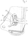
- FIG. 2 shows a perspective view of FIG. 1 from which the easy accessibility to the release devices 10 shows.
Description
Die vorliegende Erfindung betrifft einen Kran mit den Merkmalen des Anspruchs 1.The present invention relates to a crane having the features of claim 1.
Ein gattungsgemäßer Kran kann mit seinem Grundgestell an einem Fahrzeug oder einem stationären Untergrund angeordnet werden. An der Kransäule sind ein oder mehrere Kranarme schwenkbar gelagert.A generic crane can be arranged with its base frame to a vehicle or a stationary ground. One or more crane arms are pivotally mounted on the crane column.
Ein gattungsgemäßer Kran (siehe zum Beispiel
Der in der
Nachteilig ist also, dass der Drehverteiler selbst nur sehr umständlich (zum Beispiel für ein Service) demontierbar bzw. wieder montierbar ist. Die Demontage bzw. Montage muss nach oben oder unten aus dem rohrförmigen Säulenunterteil der Kransäule heraus bzw. hinein erfolgen.The disadvantage is therefore that the rotary distributor itself only very cumbersome (for example for a service) can be removed or re-assembled. The disassembly or assembly must be done up or down from the tubular column bottom of the crane column out or in.
Es gibt auch nicht gattungsgemäße Kräne, bei welchen die Kransäule über die Drehvorrichtung auf dem Grundgestell aufsitzt, also nicht in dieses hineinragt. Der Drehverteiler ist größtenteils im Grundgestell angeordnet und ragt nur geringfügig in die Kransäule hinein. Auch bei diesen Kränen ist der Drehverteiler im Bereich der Lösevorrichtung nur sehr schwer zugänglich und muss zu Servicezwecken von unten her demontiert werden.There are also non-generic cranes, in which the crane pillar on the rotary device is seated on the base frame, so it does not protrude into this. The rotary distributor is largely arranged in the base frame and protrudes only slightly into the crane column. Even with these cranes, the rotary distributor in the area of the release device is very difficult to access and must be disassembled for service purposes from below.
Aufgabe der Erfindung ist die Erleichterung der Zugänglichkeit des Drehverteilers bei einem gattungsgemäßen Kran.The object of the invention is to facilitate the accessibility of the rotary distributor in a generic crane.
Diese Aufgabe wird durch einen Kran mit den Merkmalen des Anspruchs 1 gelöst.This object is achieved by a crane having the features of claim 1.
Bei der Erfindung kommt also ein Drehverteiler zum Einsatz, der oberhalb der oberen Lagerstelle angeordnet ist, wobei eine Eingangsstelle für die wenigstens eine Leitung ebenfalls oberhalb der oberen Lagerstelle angeordnet ist. Eine Lösevorrichtung zum Lösen der Verbindung zwischen der wenigstens einen Leitung und dem Drehverteiler ist im Bereich der Eingangsstelle angeordnet. Über eine in der Höhe der Lösevorrichtung in der Kransäule angeordnete Öffnung kann von außerhalb der Kransäule ein Zugriff auf die Lösevorrichtung erfolgen. Die Demontage und die Montage des Drehverteilers, kann so auf einfache Weise erfolgen. Im Betrieb sind die Leitungen aufgrund des Verlaufs innerhalb der Kransäule dennoch geschützt.In the invention, therefore, a rotary distributor is used, which is arranged above the upper bearing, wherein an input point for the at least one line is also arranged above the upper bearing point. A release device for releasing the connection between the at least one line and the rotary distributor is arranged in the region of the entry point. An opening arranged at the level of the release device in the crane column can be used to access the release device from outside the crane column. The disassembly and assembly of the rotary distributor, can be done in a simple manner. In operation, the lines are still protected due to the course within the crane column.
Vorteilhafte Ausführungsformen der Erfindung sind in den abhängigen Ansprüchen geschützt.Advantageous embodiments of the invention are protected in the dependent claims.
In der Praxis werden mehrere Leitungen, zum Beispiel Hydraulik- oder Elektrikleitungen vorgesehen sein.In practice, multiple lines, such as hydraulic or electrical lines will be provided.
Besonders bevorzugt, ist die in der Kransäule ausgebildete Öffnung so groß, dass der Drehverteiler für die Demontage bzw. Montage durch sie hindurch bewegt werden kann.Particularly preferably, the opening formed in the crane column is so large that the rotary distributor can be moved through it for disassembly or assembly.
Die Öffnung kann je nach Lage der Lösevorrichtung im rohrförmigen Säulenunterteil oder im Säulenoberteil angeordnet sein.Depending on the position of the release device, the opening can be arranged in the tubular lower part of the column or in the upper part of the column.
Die in der Kransäule angeordnete Öffnung kann, wenn kein Zugang zum Drehverteiler erforderlich ist, durch einen entfernbaren Deckel verschlossen sein.The opening arranged in the crane column, if no access to the rotary distributor is required, can be closed by a removable cover.
Ein Ausführungsbeispiel der Erfindung sei anhand der
Die
Säulenoberteil 2. Am Säulenoberteil 2 sind nicht dargestellte Kranarme verschwenkbar angeordnet.Column
Die Kransäule 1 ist mit ihrem rohrförmigen Säulenunterteil 3 über eine untere Lagerstelle 5 und eine obere Lagerstelle 6 an einem Grundgestell 4 gelagert. Im Bereich der unteren Lagerstelle 5 greift eine nicht näher dargestellte, weil dem Stand der Technik entsprechende Drehvorrichtung an der Kransäule 1 an um diese unbegrenzt relativ zum Grundgestell 4 zu verdrehen. Am rohrförmigen Säulenunterteil 3 ist ein Säulenoberteil 2 angeordnet, an welchem Kranarme angebracht sind.The crane column 1 is mounted with its tubular column lower part 3 via a
Im gezeigten Ausführungsbeispiel sind vier Leitungen 7 erkennbar, die von unterhalb der unteren Lagerstelle 5 in den rohrförmigen Säulenunterteil 3 eintreten und über die obere Lagerstelle 6 über Lösevorrichtungen 10 mit Eingangsstellen 15 eines Drehverteilers 8 verbunden sind. Von den exemplarisch dargestellten Leitungen 7 dienen die dünner gezeichnete Leitung 7 und die dicker gezeichneten Leitungen 7 dem Transport von Hydraulikflüssigkeit.In the illustrated embodiment, four
In der Figur sind drei Ausgänge 11 erkennbar die über den zweiteiligen Drehverteiler 8 so mit den Eingangsstellen 15 verbunden sind, dass die Übertragung des in den Leitungen 7 befindlichen Mediums auch bei einer unbegrenzten Drehung der Kransäule 1 relativ zum Grundgestell 4 ungestört erfolgen kann. Der Aufbau des Drehverteilers 8 entspricht dem Stand der Technik und muss daher nicht näher beschrieben werden.In the figure, three outputs 11 can be seen which are connected via the two-part
Über die hier am Säulenoberteil 2 angeordnete Öffnung 9 ist von außerhalb der Kransäule 1 ein Zugriff auf die Lösevorrichtungen 10 möglich, was die Demontage bzw. Montage des Drehverteilers 8 im Vergleich zum Stand der Technik wesentlich erleichtert. Die Öffnung 9 ist so groß ausgebildet, dass der Drehverteiler 8 durch sie hindurch bewegt werden kann.About the arranged here on the
Ist wie in der
Alternativ oder zusätzlich kann vorgesehen sein, dass das Rohr 12 im Bereich der Lösevorrichtungen 10 einen Durchbruch 14 (oder eine nicht dargestellte Ausnehmung, die sich bis zu seiner Stirnseite erstreckt) aufweist. Dann kann unmittelbar auf die Lösevorrichtungen 10 zugegriffen werden.Alternatively or additionally, it may be provided that the
Das Rohr 12 kann an seinem unteren Ende mit dem Grundgestell 4 verbunden, zum Beispiel verschweißt, sein.The
Claims (9)
- A crane having a crane mast (1) which has a tubular mast lower portion (3) and a main frame (5) in which a lower mounting location (5) and an upper mounting location (6) for the mast lower portion (3) of the crane mast (1) are disposed one above the other, wherein the mast lower portion (3) is rotatable relative to the main frame (4) by way of a rotary device and wherein at least one line (7) extends from below the lower mounting location (5) to the upper mounting location (6), characterised in that the at least one line (7) is connected above the upper mounting location (6) to an intake location (15) of a rotary distributor (8), wherein a release device (10) for releasing the connection between the at least one line (7) and the rotary distributor (8) is arranged in the region of the intake location (15) and that the crane mast (1) at the height of the release device (10) has an opening (9) which permits access to the release device (10) from outside the crane mast (1).
- A crane as set forth in claim 1 characterised in that the opening (9) in the crane mast (1) is so large that the rotary distributor (8) is movable through it.
- A crane as set forth in claim 1 or claim 2 characterised in that the opening (9) is arranged in the mast upper portion (2).
- A crane as set forth in at least one of claims 1 through 3 characterised in that the opening (9) is closed by a removable cover.
- A crane as set forth in at least one of claims 1 through 4 characterised in that the rotary distributor (8) is connected to a tube (12) in which the at least one line (7) extends within the tubular mast lower portion (3).
- A crane as set forth in claim 5 characterised in that at its lower end the tube (12) is connected to the main frame (4).
- A crane as set forth in claim 5 or claim 6 characterised in that fixing locations (13) of the rotary distributor (8) are accessible at the tube (12) by way of the opening (9).
- A crane as set forth in at least one of claims 5 through 7 characterised in that in the region of the release device (10) the tube (12) has an aperture (14) or a cut-out.
- A crane as set forth in at least one of claims 1 through 8 characterised in that the crane is in the form of a vehicle crane, preferably a loading crane.
Priority Applications (9)
| Application Number | Priority Date | Filing Date | Title |
|---|---|---|---|
| PL14169680T PL2947038T3 (en) | 2014-05-23 | 2014-05-23 | Crane |
| SI201430399T SI2947038T1 (en) | 2014-05-23 | 2014-05-23 | Crane |
| EP14169680.7A EP2947038B1 (en) | 2014-05-23 | 2014-05-23 | Crane |
| ES14169680.7T ES2643603T3 (en) | 2014-05-23 | 2014-05-23 | Crane |
| KR1020150069624A KR20150135108A (en) | 2014-05-23 | 2015-05-19 | Crane |
| BR102015011449-4A BR102015011449B1 (en) | 2014-05-23 | 2015-05-19 | crane |
| JP2015101463A JP6113783B2 (en) | 2014-05-23 | 2015-05-19 | crane |
| RU2015119231/11A RU2595107C1 (en) | 2014-05-23 | 2015-05-21 | Crane |
| CN201510263981.3A CN105084227B (en) | 2014-05-23 | 2015-05-22 | Crane |
Applications Claiming Priority (1)
| Application Number | Priority Date | Filing Date | Title |
|---|---|---|---|
| EP14169680.7A EP2947038B1 (en) | 2014-05-23 | 2014-05-23 | Crane |
Publications (2)
| Publication Number | Publication Date |
|---|---|
| EP2947038A1 EP2947038A1 (en) | 2015-11-25 |
| EP2947038B1 true EP2947038B1 (en) | 2017-07-12 |
Family
ID=50771199
Family Applications (1)
| Application Number | Title | Priority Date | Filing Date |
|---|---|---|---|
| EP14169680.7A Active EP2947038B1 (en) | 2014-05-23 | 2014-05-23 | Crane |
Country Status (9)
| Country | Link |
|---|---|
| EP (1) | EP2947038B1 (en) |
| JP (1) | JP6113783B2 (en) |
| KR (1) | KR20150135108A (en) |
| CN (1) | CN105084227B (en) |
| BR (1) | BR102015011449B1 (en) |
| ES (1) | ES2643603T3 (en) |
| PL (1) | PL2947038T3 (en) |
| RU (1) | RU2595107C1 (en) |
| SI (1) | SI2947038T1 (en) |
Family Cites Families (12)
| Publication number | Priority date | Publication date | Assignee | Title |
|---|---|---|---|---|
| AT371788B (en) | 1981-02-11 | 1983-07-25 | Penz Rochus | SWIVEL DRIVE FOR THE COLUMN OF A TURNING CRANE |
| JPH09142775A (en) * | 1995-11-21 | 1997-06-03 | Tadano Ltd | Rotary joint attaching/detaching mechanism of rotary crane |
| JP2000177984A (en) * | 1998-12-16 | 2000-06-27 | Tadano Ltd | Rotary joint attaching structure for hydraulic work machine |
| RU2169694C2 (en) * | 1999-01-05 | 2001-06-27 | ЗАО "НК Уралтерминалмаш" | Crane-manipulator set load-lifting boom |
| KR101060939B1 (en) * | 2003-12-18 | 2011-08-30 | 히다찌 겐끼 가부시키가이샤 | Swivel Joint Of Construction Machinery |
| JP4272983B2 (en) * | 2003-12-26 | 2009-06-03 | 株式会社キトー | Jib crane |
| AT10273U1 (en) * | 2007-05-03 | 2008-12-15 | Palfinger Ag | ADJUSTMENT MECHANISM FOR A WINCH |
| CN201325837Y (en) * | 2008-11-24 | 2009-10-14 | 徐州重型机械有限公司 | Self-dismounting split type turntable and crawling crane therewith |
| CN201354136Y (en) * | 2009-01-22 | 2009-12-02 | 淮安远航船用设备制造有限公司 | Multifunctional crane |
| CN202201654U (en) * | 2011-08-08 | 2012-04-25 | 长沙桑尼重工机械有限公司 | Intelligent lorry-mounted crane with intelligent operation control system |
| CN202302480U (en) * | 2011-10-19 | 2012-07-04 | 江阴市长龄机械制造有限公司 | Multi-channel hydraulic gyrating joint |
| CN202296897U (en) * | 2011-11-07 | 2012-07-04 | 奥力通起重机(北京)有限公司 | Split column suspension crane |
-
2014
- 2014-05-23 ES ES14169680.7T patent/ES2643603T3/en active Active
- 2014-05-23 SI SI201430399T patent/SI2947038T1/en unknown
- 2014-05-23 PL PL14169680T patent/PL2947038T3/en unknown
- 2014-05-23 EP EP14169680.7A patent/EP2947038B1/en active Active
-
2015
- 2015-05-19 BR BR102015011449-4A patent/BR102015011449B1/en active IP Right Grant
- 2015-05-19 KR KR1020150069624A patent/KR20150135108A/en not_active Application Discontinuation
- 2015-05-19 JP JP2015101463A patent/JP6113783B2/en active Active
- 2015-05-21 RU RU2015119231/11A patent/RU2595107C1/en active
- 2015-05-22 CN CN201510263981.3A patent/CN105084227B/en active Active
Also Published As
| Publication number | Publication date |
|---|---|
| SI2947038T1 (en) | 2017-11-30 |
| KR20150135108A (en) | 2015-12-02 |
| CN105084227A (en) | 2015-11-25 |
| CN105084227B (en) | 2017-08-22 |
| JP2015224139A (en) | 2015-12-14 |
| PL2947038T3 (en) | 2018-02-28 |
| ES2643603T3 (en) | 2017-11-23 |
| RU2595107C1 (en) | 2016-08-20 |
| BR102015011449B1 (en) | 2021-07-06 |
| BR102015011449A2 (en) | 2016-03-22 |
| JP6113783B2 (en) | 2017-04-12 |
| EP2947038A1 (en) | 2015-11-25 |
Similar Documents
| Publication | Publication Date | Title |
|---|---|---|
| EP2984253B1 (en) | Mobile concrete pump with distributing boom and support device | |
| DE102015100439B3 (en) | Easy to maintain telescopic swivel arm and working or operating procedures | |
| EP2947038B1 (en) | Crane | |
| DE3307893A1 (en) | Rotating tower crane with jib and counter-jib | |
| EP2897891B1 (en) | Perimeter frame, method to install a perimeter frame and use of a perimeter frame to connect a tower crane with an object | |
| EP2947037B1 (en) | Crane | |
| DE102014206833A1 (en) | Mobile concrete pump with supporting device and concrete distributor mast | |
| DE1185353B (en) | Rotary crane with counterweight | |
| EP3639652B1 (en) | Forest trailer | |
| DE2323887A1 (en) | LIFTING EQUIPMENT | |
| DE2747291A1 (en) | Swivelling crane with lifting equipment - has load carrier in telescopic tube on swivelling overhanging arm | |
| DE102015000473B4 (en) | Crane with bracing | |
| DE3628703A1 (en) | Opening device for covers of ground orifices, especially for inspection orifices of sewage systems | |
| DE933738C (en) | On the ground in all directions movable device, especially for bringing in or pulling foundation stakes and the like. like | |
| DE102014013666A1 (en) | Mobile shaft winch | |
| DE473706C (en) | Waelzwehr with a movable weir attachment | |
| DE504961C (en) | Arrangement of cable termination boxes | |
| DE202017004436U1 (en) | Ironing board with hinged Aufstellgestänge | |
| DE2403412A1 (en) | LIFTING DEVICE FOR HEAVY LOADS | |
| DE1266470B (en) | Work device designed as a vehicle | |
| DE1261647B (en) | Slewing crane with two-part boom | |
| DE102015001021A1 (en) | Inspection device for channels, wells or the like | |
| DE1285703B (en) | Telescopic boom with articulated luffing arm for a crane | |
| DE1556345A1 (en) | Mobile fork jib crane | |
| DE7732531U1 (en) | CONVEYOR DEVICES, IN PARTICULAR JIB CRANES |
Legal Events
| Date | Code | Title | Description |
|---|---|---|---|
| PUAI | Public reference made under article 153(3) epc to a published international application that has entered the european phase |
Free format text: ORIGINAL CODE: 0009012 |
|
| 17P | Request for examination filed |
Effective date: 20150209 |
|
| AK | Designated contracting states |
Kind code of ref document: A1 Designated state(s): AL AT BE BG CH CY CZ DE DK EE ES FI FR GB GR HR HU IE IS IT LI LT LU LV MC MK MT NL NO PL PT RO RS SE SI SK SM TR |
|
| AX | Request for extension of the european patent |
Extension state: BA ME |
|
| GRAP | Despatch of communication of intention to grant a patent |
Free format text: ORIGINAL CODE: EPIDOSNIGR1 |
|
| STAA | Information on the status of an ep patent application or granted ep patent |
Free format text: STATUS: GRANT OF PATENT IS INTENDED |
|
| INTG | Intention to grant announced |
Effective date: 20161223 |
|
| GRAS | Grant fee paid |
Free format text: ORIGINAL CODE: EPIDOSNIGR3 |
|
| GRAA | (expected) grant |
Free format text: ORIGINAL CODE: 0009210 |
|
| STAA | Information on the status of an ep patent application or granted ep patent |
Free format text: STATUS: THE PATENT HAS BEEN GRANTED |
|
| AK | Designated contracting states |
Kind code of ref document: B1 Designated state(s): AL AT BE BG CH CY CZ DE DK EE ES FI FR GB GR HR HU IE IS IT LI LT LU LV MC MK MT NL NO PL PT RO RS SE SI SK SM TR |
|
| REG | Reference to a national code |
Ref country code: GB Ref legal event code: FG4D Free format text: NOT ENGLISH |
|
| REG | Reference to a national code |
Ref country code: CH Ref legal event code: EP |
|
| REG | Reference to a national code |
Ref country code: AT Ref legal event code: REF Ref document number: 908126 Country of ref document: AT Kind code of ref document: T Effective date: 20170715 |
|
| REG | Reference to a national code |
Ref country code: IE Ref legal event code: FG4D Free format text: LANGUAGE OF EP DOCUMENT: GERMAN |
|
| REG | Reference to a national code |
Ref country code: DE Ref legal event code: R096 Ref document number: 502014004532 Country of ref document: DE |
|
| REG | Reference to a national code |
Ref country code: SE Ref legal event code: TRGR |
|
| REG | Reference to a national code |
Ref country code: NL Ref legal event code: MP Effective date: 20170712 |
|
| REG | Reference to a national code |
Ref country code: ES Ref legal event code: FG2A Ref document number: 2643603 Country of ref document: ES Kind code of ref document: T3 Effective date: 20171123 |
|
| REG | Reference to a national code |
Ref country code: LT Ref legal event code: MG4D |
|
| PG25 | Lapsed in a contracting state [announced via postgrant information from national office to epo] |
Ref country code: LT Free format text: LAPSE BECAUSE OF FAILURE TO SUBMIT A TRANSLATION OF THE DESCRIPTION OR TO PAY THE FEE WITHIN THE PRESCRIBED TIME-LIMIT Effective date: 20170712 Ref country code: NL Free format text: LAPSE BECAUSE OF FAILURE TO SUBMIT A TRANSLATION OF THE DESCRIPTION OR TO PAY THE FEE WITHIN THE PRESCRIBED TIME-LIMIT Effective date: 20170712 Ref country code: HR Free format text: LAPSE BECAUSE OF FAILURE TO SUBMIT A TRANSLATION OF THE DESCRIPTION OR TO PAY THE FEE WITHIN THE PRESCRIBED TIME-LIMIT Effective date: 20170712 Ref country code: NO Free format text: LAPSE BECAUSE OF FAILURE TO SUBMIT A TRANSLATION OF THE DESCRIPTION OR TO PAY THE FEE WITHIN THE PRESCRIBED TIME-LIMIT Effective date: 20171012 |
|
| PG25 | Lapsed in a contracting state [announced via postgrant information from national office to epo] |
Ref country code: BG Free format text: LAPSE BECAUSE OF FAILURE TO SUBMIT A TRANSLATION OF THE DESCRIPTION OR TO PAY THE FEE WITHIN THE PRESCRIBED TIME-LIMIT Effective date: 20171012 Ref country code: GR Free format text: LAPSE BECAUSE OF FAILURE TO SUBMIT A TRANSLATION OF THE DESCRIPTION OR TO PAY THE FEE WITHIN THE PRESCRIBED TIME-LIMIT Effective date: 20171013 Ref country code: IS Free format text: LAPSE BECAUSE OF FAILURE TO SUBMIT A TRANSLATION OF THE DESCRIPTION OR TO PAY THE FEE WITHIN THE PRESCRIBED TIME-LIMIT Effective date: 20171112 Ref country code: LV Free format text: LAPSE BECAUSE OF FAILURE TO SUBMIT A TRANSLATION OF THE DESCRIPTION OR TO PAY THE FEE WITHIN THE PRESCRIBED TIME-LIMIT Effective date: 20170712 Ref country code: RS Free format text: LAPSE BECAUSE OF FAILURE TO SUBMIT A TRANSLATION OF THE DESCRIPTION OR TO PAY THE FEE WITHIN THE PRESCRIBED TIME-LIMIT Effective date: 20170712 |
|
| REG | Reference to a national code |
Ref country code: DE Ref legal event code: R097 Ref document number: 502014004532 Country of ref document: DE |
|
| PG25 | Lapsed in a contracting state [announced via postgrant information from national office to epo] |
Ref country code: CZ Free format text: LAPSE BECAUSE OF FAILURE TO SUBMIT A TRANSLATION OF THE DESCRIPTION OR TO PAY THE FEE WITHIN THE PRESCRIBED TIME-LIMIT Effective date: 20170712 Ref country code: RO Free format text: LAPSE BECAUSE OF FAILURE TO SUBMIT A TRANSLATION OF THE DESCRIPTION OR TO PAY THE FEE WITHIN THE PRESCRIBED TIME-LIMIT Effective date: 20170712 Ref country code: DK Free format text: LAPSE BECAUSE OF FAILURE TO SUBMIT A TRANSLATION OF THE DESCRIPTION OR TO PAY THE FEE WITHIN THE PRESCRIBED TIME-LIMIT Effective date: 20170712 |
|
| PLBE | No opposition filed within time limit |
Free format text: ORIGINAL CODE: 0009261 |
|
| STAA | Information on the status of an ep patent application or granted ep patent |
Free format text: STATUS: NO OPPOSITION FILED WITHIN TIME LIMIT |
|
| REG | Reference to a national code |
Ref country code: FR Ref legal event code: PLFP Year of fee payment: 5 |
|
| PG25 | Lapsed in a contracting state [announced via postgrant information from national office to epo] |
Ref country code: SM Free format text: LAPSE BECAUSE OF FAILURE TO SUBMIT A TRANSLATION OF THE DESCRIPTION OR TO PAY THE FEE WITHIN THE PRESCRIBED TIME-LIMIT Effective date: 20170712 Ref country code: SK Free format text: LAPSE BECAUSE OF FAILURE TO SUBMIT A TRANSLATION OF THE DESCRIPTION OR TO PAY THE FEE WITHIN THE PRESCRIBED TIME-LIMIT Effective date: 20170712 Ref country code: EE Free format text: LAPSE BECAUSE OF FAILURE TO SUBMIT A TRANSLATION OF THE DESCRIPTION OR TO PAY THE FEE WITHIN THE PRESCRIBED TIME-LIMIT Effective date: 20170712 |
|
| 26N | No opposition filed |
Effective date: 20180413 |
|
| PG25 | Lapsed in a contracting state [announced via postgrant information from national office to epo] |
Ref country code: MT Free format text: LAPSE BECAUSE OF FAILURE TO SUBMIT A TRANSLATION OF THE DESCRIPTION OR TO PAY THE FEE WITHIN THE PRESCRIBED TIME-LIMIT Effective date: 20170712 |
|
| REG | Reference to a national code |
Ref country code: CH Ref legal event code: PL |
|
| REG | Reference to a national code |
Ref country code: BE Ref legal event code: MM Effective date: 20180531 |
|
| PG25 | Lapsed in a contracting state [announced via postgrant information from national office to epo] |
Ref country code: MC Free format text: LAPSE BECAUSE OF FAILURE TO SUBMIT A TRANSLATION OF THE DESCRIPTION OR TO PAY THE FEE WITHIN THE PRESCRIBED TIME-LIMIT Effective date: 20170712 |
|
| REG | Reference to a national code |
Ref country code: IE Ref legal event code: MM4A |
|
| PG25 | Lapsed in a contracting state [announced via postgrant information from national office to epo] |
Ref country code: CH Free format text: LAPSE BECAUSE OF NON-PAYMENT OF DUE FEES Effective date: 20180531 Ref country code: LI Free format text: LAPSE BECAUSE OF NON-PAYMENT OF DUE FEES Effective date: 20180531 |
|
| PG25 | Lapsed in a contracting state [announced via postgrant information from national office to epo] |
Ref country code: LU Free format text: LAPSE BECAUSE OF NON-PAYMENT OF DUE FEES Effective date: 20180523 |
|
| PG25 | Lapsed in a contracting state [announced via postgrant information from national office to epo] |
Ref country code: IE Free format text: LAPSE BECAUSE OF NON-PAYMENT OF DUE FEES Effective date: 20180523 |
|
| PG25 | Lapsed in a contracting state [announced via postgrant information from national office to epo] |
Ref country code: BE Free format text: LAPSE BECAUSE OF NON-PAYMENT OF DUE FEES Effective date: 20180531 |
|
| PG25 | Lapsed in a contracting state [announced via postgrant information from national office to epo] |
Ref country code: TR Free format text: LAPSE BECAUSE OF FAILURE TO SUBMIT A TRANSLATION OF THE DESCRIPTION OR TO PAY THE FEE WITHIN THE PRESCRIBED TIME-LIMIT Effective date: 20170712 |
|
| PG25 | Lapsed in a contracting state [announced via postgrant information from national office to epo] |
Ref country code: PT Free format text: LAPSE BECAUSE OF FAILURE TO SUBMIT A TRANSLATION OF THE DESCRIPTION OR TO PAY THE FEE WITHIN THE PRESCRIBED TIME-LIMIT Effective date: 20170712 |
|
| PG25 | Lapsed in a contracting state [announced via postgrant information from national office to epo] |
Ref country code: HU Free format text: LAPSE BECAUSE OF FAILURE TO SUBMIT A TRANSLATION OF THE DESCRIPTION OR TO PAY THE FEE WITHIN THE PRESCRIBED TIME-LIMIT; INVALID AB INITIO Effective date: 20140523 Ref country code: CY Free format text: LAPSE BECAUSE OF FAILURE TO SUBMIT A TRANSLATION OF THE DESCRIPTION OR TO PAY THE FEE WITHIN THE PRESCRIBED TIME-LIMIT Effective date: 20170712 Ref country code: MK Free format text: LAPSE BECAUSE OF NON-PAYMENT OF DUE FEES Effective date: 20170712 |
|
| PG25 | Lapsed in a contracting state [announced via postgrant information from national office to epo] |
Ref country code: AL Free format text: LAPSE BECAUSE OF FAILURE TO SUBMIT A TRANSLATION OF THE DESCRIPTION OR TO PAY THE FEE WITHIN THE PRESCRIBED TIME-LIMIT Effective date: 20170712 |
|
| P01 | Opt-out of the competence of the unified patent court (upc) registered |
Effective date: 20230601 |
|
| PGFP | Annual fee paid to national office [announced via postgrant information from national office to epo] |
Ref country code: IT Payment date: 20230525 Year of fee payment: 10 Ref country code: FR Payment date: 20230523 Year of fee payment: 10 Ref country code: ES Payment date: 20230613 Year of fee payment: 10 Ref country code: DE Payment date: 20230530 Year of fee payment: 10 |
|
| PGFP | Annual fee paid to national office [announced via postgrant information from national office to epo] |
Ref country code: SI Payment date: 20230503 Year of fee payment: 10 Ref country code: SE Payment date: 20230524 Year of fee payment: 10 Ref country code: PL Payment date: 20230427 Year of fee payment: 10 Ref country code: FI Payment date: 20230526 Year of fee payment: 10 Ref country code: AT Payment date: 20230531 Year of fee payment: 10 |
|
| PGFP | Annual fee paid to national office [announced via postgrant information from national office to epo] |
Ref country code: GB Payment date: 20230523 Year of fee payment: 10 |