EP2946971A2 - Système de chargement pour un véhicule - Google Patents
Système de chargement pour un véhicule Download PDFInfo
- Publication number
- EP2946971A2 EP2946971A2 EP15001554.3A EP15001554A EP2946971A2 EP 2946971 A2 EP2946971 A2 EP 2946971A2 EP 15001554 A EP15001554 A EP 15001554A EP 2946971 A2 EP2946971 A2 EP 2946971A2
- Authority
- EP
- European Patent Office
- Prior art keywords
- vehicle
- lifting device
- loading
- during
- actuator
- Prior art date
- Legal status (The legal status is an assumption and is not a legal conclusion. Google has not performed a legal analysis and makes no representation as to the accuracy of the status listed.)
- Withdrawn
Links
Images


Classifications
-
- B—PERFORMING OPERATIONS; TRANSPORTING
- B60—VEHICLES IN GENERAL
- B60P—VEHICLES ADAPTED FOR LOAD TRANSPORTATION OR TO TRANSPORT, TO CARRY, OR TO COMPRISE SPECIAL LOADS OR OBJECTS
- B60P1/00—Vehicles predominantly for transporting loads and modified to facilitate loading, consolidating the load, or unloading
- B60P1/64—Vehicles predominantly for transporting loads and modified to facilitate loading, consolidating the load, or unloading the load supporting or containing element being readily removable
- B60P1/6418—Vehicles predominantly for transporting loads and modified to facilitate loading, consolidating the load, or unloading the load supporting or containing element being readily removable the load-transporting element being a container or similar
- B60P1/6427—Vehicles predominantly for transporting loads and modified to facilitate loading, consolidating the load, or unloading the load supporting or containing element being readily removable the load-transporting element being a container or similar the load-transporting element being shifted horizontally in a fore and aft direction, combined or not with a vertical displacement
Definitions
- the invention relates to a charging system for a vehicle, with which a structure between a loaded on the vehicle transport position and a loaded from the vehicle loading position is reciprocated such that a loading floor of the structure during its charging to the vehicle and during his Discharge of the vehicle is oriented substantially horizontally.
- the invention relates to a vehicle, in particular a load vehicle, with at least one structure.
- the invention relates to a method for loading and unloading a vehicle on the vehicle or the vehicle, wherein a loading floor of the structure during its loading on the vehicle and during its unloading from the vehicle in a substantially horizontal orientation kept becomes.
- a truck which has a loading device which is arranged along a running in the vehicle longitudinal direction path movable on a chassis of the supported truck.
- the loading device comprises a vertical frame on which a lifting device is arranged vertically displaceable.
- the object of the invention is to make it easy and fast to charge and unload a superstructure on or from a vehicle without severely restricting the payload of one of a vehicle.
- the structure can be moved back and forth in a vertical direction between the lifting position and the loading position by means of the first lifting device and the second lifting device, so that the force required to lift and lower the structure in comparison to the disclosure of DE 28 44 044 A1 is significantly reduced, in which no corresponding second lifting device is present.
- the forces during lowering and lifting of the structure are distributed to the first lifting device and the second lifting device, so that in particular the first lifting device structurally significantly less material-consuming and can be configured less complicated than the loading device according to DE 28 44 044 A1 ,
- the structure can be loaded and unloaded like a conventional, fixed assembly.
- the structure can assume its loading position, for example, by lowering the loading floor to the level of a loading ramp or down to the ground.
- the structure can be placed on a support structure to take his loading position.
- the fact that the loading floor of the superstructure is oriented substantially horizontally during its loading onto the vehicle and during its unloading from the vehicle means that the loading floor during its loading and unloading can be oriented such that, for example, one located on the loading floor Charge must not be secured against slipping on the loading floor due to an inclined position of the loading floor. This does not mean that the loading floor can not be slightly tilted during its loading and unloading.
- the loading floor is inclined at its loading and unloading less than 20 °, preferably less than 10 °.
- the guided relative movement between the vehicle and the structure in the longitudinal direction of the vehicle which can be carried out by means of the movement device which can be arranged on the vehicle, such that the structure can assume a rearward position relative to the vehicle with respect to the direction of travel of the vehicle, in which the structure projects rearwardly beyond the vehicle , can be done by using on the structure and / or the vehicle can be arranged guide means.
- guide means can be used, for example, in the longitudinal direction of the vehicle aligned guide rails and cooperating with the guide rails sliding or rolling body.
- a guided relative movement can be effected by the vehicle is stationary and the structure is moved relative to the vehicle, that the structure is held stationary while the vehicle is moved relative to the structure in the direction of travel, or that a combination of these movements takes place.
- the movement device can be arranged on the vehicle such that the structure is at least partially supported on the vehicle during the guided relative movements, part of the structure is carried by the vehicle during the guided relative movements.
- the second lifting device is activated at the latest when the center of gravity of the structure leaves the vehicle at the rear in a guided relative movement.
- the first lifting device may be arranged at a rear region of the vehicle or at a forward end region of the structure with respect to the direction of travel of the vehicle. In the latter case, the first lifting device is moved with a guided relative movement between the body and the vehicle, in which the vehicle is held stationary, with the structure.
- the charging system can also have two or more first lifting devices.
- the vehicle rearward portion of the structure, on which the second lifting device can be disposed preferably extends from the rear end of the structure almost to the center of the structure.
- the second lifting device can be arranged in particular in a lower region of the structure, in particular under the structure.
- the charging system can also have two or more second lifting devices.
- the first lifting device and the second lifting device can be connected to each other at least in their effect.
- the first lifting device and the second lifting device may have at least one common actuator or a manual drive.
- the charging system can have at least one device by means of which the movement device, the first lifting device and / or the second lifting device can be coupled to each other at least partially physically and / or at least in their effects.
- the charging system may also have more than two coupled or uncoupled lifting devices.
- the charging system may comprise one or more sensors for detecting relative positions of the structure relative to the vehicle, via which executable movements, in particular lifting movements, of the structure relative to the vehicle can be automated by means of the charging system.
- the lifting devices and / or the movement device can be at least partially manually operable.
- the movement device has at least one controllable actuator, which acts on the one hand on the vehicle and on the other hand on the structure.
- the actuator can be designed, for example, mechanically, electromechanically, hydraulically or pneumatically.
- the actuator can act on at least one traction means, such as a pull rope or the like, or a pushing means, such as a push rod or the like, on the body and / or the vehicle.
- the movement device can also have two or more actuators.
- the first lifting device has at least one controllable actuator, which acts on the one hand on the vehicle and on the other hand on the structure.
- the actuator can be designed, for example, mechanically, electromechanically, hydraulically or pneumatically.
- the first lifting device may also have two or more actuators.
- the second lifting device has at least one controllable actuator and at least one support member, wherein the support member by means of the actuator relative to the structure between a rest position and a support position is movable back and forth.
- the actuator can be designed, for example, mechanically, electromechanically, hydraulically or pneumatically.
- the second lifting device may also have two or more actuators and / or support members.
- the structure may be supported in its rear region via at least one support member on a floor or the like.
- the actuators of the first lifting device and the second lifting device can be controlled individually or at least partially together.
- the support member is a part of a telescopic support or designed as a joint support.
- a telescopic support may for example be formed by a hydraulic cylinder or a pneumatic cylinder or comprise a spindle or a rack.
- a Joint support comprises at least two articulated support parts.
- At least one base, at least one roller or at least one sliding surface is arranged on a bottom end of the support member.
- a base is advantageous when the structure is held stationary during a guided relative movement between the structure and the vehicle while the vehicle is moving.
- a role is advantageous when the vehicle is held stationary during a guided relative movement between the body and the vehicle while the body is moving.
- a sliding surface disposed on the bottom end of the support member may act corresponding to a roller. At the end of the support member and two or more feet, rollers or sliding surfaces may be arranged.
- the charging system has at least one control device, by means of which the actuator of the moving device, the actuator of the first lifting device and / or the actuator of the second lifting device can be controlled.
- the control device is electronically formed and communicatively connected to at least one of the actuators. It can be arranged on the vehicle cooperating with the control unit operating unit, which is manually operable to control the at least one actuator.
- the charging system comprises at least one locking device, by means of which the transport position of the structure is securable.
- the locking device may for example be manually operable, mechanical, electromechanical, hydraulic or pneumatic.
- the locking device can be connected in terms of communication technology with the control device and be controlled via this and the operating unit.
- the locking device may be technically connected to the movement and / or with the lifting devices or act independently thereof.
- a vehicle, in particular load vehicle proposed with at least one structure, characterized by at least one charging system according to one of the aforementioned embodiments or any combination thereof.
- the structure can be designed as a platform, closed, at least partially open or designed to accommodate swap bodies or smaller structures.
- the structure may have at least one possibility for crossing over, which may be designed, for example, as a side wall, which may act as a ramp at the same time.
- the vehicle may be a truck or a trailer.
- the vehicle may have at least one support for supporting the vehicle on the ground in the rear area.
- the structure can be decoupled from the vehicle.
- the vehicle and / or the charging system attachments such as an underrun protection, light carrier or the like, be arranged movable or removable.
- the second lifting device can first be lowered before or during the movement process, in order to carry out the lifting operation jointly or independently of the first lifting device after completion of the movement process.
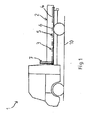
- FIG. 1 shows a schematic side view of an embodiment of a standing on a floor 10 inventive vehicle 1 in the form of a truck with befindlichem in its transport position structure 2 in the form of an open structure.
- the vehicle comprises a charging system 3, with which the body 2 between the shown on the vehicle loaded transport position and a in FIG. 4 shown unloaded from the vehicle loading position such and that a loading floor 4 of the body 2 during its charging to the vehicle 1 and during its unloading from the vehicle 1 is substantially horizontally aligned.
- the charging system 3 comprises a movement device 5 arranged on the vehicle 1, which is set up to allow guided relative movements between the vehicle 1 and the body 2 in the longitudinal direction of the vehicle 1 such that the body 2 moves relative to the vehicle 1 with respect to the direction of travel of the vehicle Can occupy the vehicle 1 rearward stroke position in which the structure 2 projecting rear side over the vehicle 1, as in FIG. 3 is shown by way of example.
- the movement device 5 is arranged on the vehicle 1 such that the structure 2 is supported on the vehicle 1 at least partially via the movement device 5 during the guided relative movements.
- a longitudinal rail 6 can be seen in the figures, which cooperates with sliding or rolling means and guides of the movement device 5, not shown.
- the movement device 3 may comprise at least one controllable actuator, not shown, which on the one hand to the vehicle 1 and on the other the structure 2 attacks.
- the charging system 3 furthermore comprises a first lifting device 7, which is arranged at a forward end region of the body 2 with respect to the direction of travel of the vehicle 1, and one in the FIGS. 2 to 4 shown, arranged at a rear relative to the direction of travel of the vehicle 1 region of the body 2 second lifting device 8, the structure 2 by means of the first lifting device 7 and the second lifting device 8 in the vertical direction between the stroke position and the loading position is movable back and forth.
- the first lifting device 7 has at least one controllable actuator, not shown, which on the one hand acts on the vehicle 1 and on the other hand on the body 2.
- the second lifting device 8 has at least one controllable actuator, not shown, and at least one in the FIGS. 3 to 4 shown support member 9, wherein the support member 9 by means of the actuator relative to the structure 2 between a rest position and a support position is movable back and forth.
- the charging system 3 comprises at least one arresting device, not shown, by means of which the transport position of the body 2 can be secured. Furthermore, the charging system 3 comprises at least one control device, not shown, by means of which the actuator of the moving device 3, the actuator of the first lifting device 7 and / or the actuator of the second lifting device 8 can be controlled.
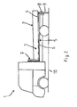
- FIG. 2 shows a schematic side view of the in FIG. 1 shown driving schis 1 in a state of charge.
- the second lifting device 8 has been actuated, whereby the support member 9 has been transferred from its rest position to the support position shown.
- the structure 2 is supported via the support member 9 from the bottom 10 so that the structure 2 is raised in its rear region for at least partially releasing the locking device.
- the support member 9 may be part of a telescopic support or designed as a joint support.
- an unillustrated base is arranged at a bottom end of the support member 9.
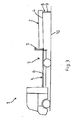
- FIG. 3 shows a schematic side view of the in FIG. 1 shown vehicle 1 with befindlichem in its stroke position structure 2.
- the structure 2 is characterized by its in FIG. 2 shown position has been transferred to the stroke position by the vehicle 1 has been moved in stationary structure 2 in the direction of travel.
- the first lifting device 7 has been displaced together with the structure 2.
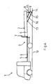
- FIG. 4 shows a schematic side view of the in FIG. 1
- the structure 2 was an actuation of the first lifting device 7 and the second lifting device 8 of his in FIG. 3 shown stroke position moves into the loading position.
- In the rear region of the structure 2 at least one charging rail 11 is arranged, via which the structure 2 can be loaded,
- FIG. 5 shows a schematic side view of another embodiment of a vehicle according to the invention 1 according to the in FIG. 2 shown charge state. Unlike in the FIGS. 1 to 4 shown embodiment, a roller 12 is disposed at the bottom end of the support member 9.
- FIG. 6 shows a schematic side view of another embodiment of a vehicle according to the invention 1 with befindlichem in its stroke position structure 2 accordingly FIG. 3 , Unlike the ones in the FIGS. 1 to 5
- the support member 9 forms a two-part joint support, wherein two support members 13 and 14 are movably connected to each other via a hinge 15. The upper end of the support member 13 is pivotally connected to the loading floor 4.
- the actuator 16 of the second lifting device 8 designed as a hydraulic cylinder can be seen, which acts on the support member 9 on the one hand in the area of the joint 15 and on the other on the loading floor 4.
- a guide strut 17 of the second lifting device 8 which acts on the one hand on the bottom-side support member 14 and on the other hand on the loading floor 4.
- the guide strut 17 causes that on actuation of the actuator 16, the bottom-side support member 14 is only slightly moved in the horizontal direction, which is particularly advantageous for a support member 9 with base.
Landscapes
- Engineering & Computer Science (AREA)
- Transportation (AREA)
- Mechanical Engineering (AREA)
- Arrangement Or Mounting Of Propulsion Units For Vehicles (AREA)
- Body Structure For Vehicles (AREA)
- Fittings On The Vehicle Exterior For Carrying Loads, And Devices For Holding Or Mounting Articles (AREA)
Applications Claiming Priority (1)
| Application Number | Priority Date | Filing Date | Title |
|---|---|---|---|
| DE102014107334.7A DE102014107334B4 (de) | 2014-05-23 | 2014-05-23 | Ladesystem für ein Fahrzeug |
Publications (1)
| Publication Number | Publication Date |
|---|---|
| EP2946971A2 true EP2946971A2 (fr) | 2015-11-25 |
Family
ID=53385426
Family Applications (1)
| Application Number | Title | Priority Date | Filing Date |
|---|---|---|---|
| EP15001554.3A Withdrawn EP2946971A2 (fr) | 2014-05-23 | 2015-05-22 | Système de chargement pour un véhicule |
Country Status (2)
| Country | Link |
|---|---|
| EP (1) | EP2946971A2 (fr) |
| DE (1) | DE102014107334B4 (fr) |
Families Citing this family (1)
| Publication number | Priority date | Publication date | Assignee | Title |
|---|---|---|---|---|
| EP4043279B1 (fr) * | 2021-02-11 | 2023-09-13 | BK-Wechseltechnik GmbH | Dispositif et procédé de remplacement d'une caisse mobile dans un camion |
Citations (1)
| Publication number | Priority date | Publication date | Assignee | Title |
|---|---|---|---|---|
| DE2844044A1 (de) | 1977-10-13 | 1979-04-26 | Wilhelmsson T | Transportvorrichtung |
Family Cites Families (7)
| Publication number | Priority date | Publication date | Assignee | Title |
|---|---|---|---|---|
| CH446925A (de) * | 1965-11-04 | 1967-11-15 | Moser Hermann | Verladeeinrichtung für Automobile und Lastwagen |
| CH521867A (de) | 1970-04-15 | 1972-04-30 | Vetter Hans | Nutzfahrzeug mit absenkbarem, vorzugsweise wechselbarem Aufbau |
| DE29608955U1 (de) * | 1996-05-10 | 1996-09-26 | Jaehne Johannes | Beladevorrichtung |
| DE20119560U1 (de) * | 2001-12-01 | 2002-02-21 | Urbach Dieter | Ladehilfsvorrichtung |
| US6883849B2 (en) * | 2002-07-11 | 2005-04-26 | Gerald Hebert | Truck bed extender |
| US20080279665A1 (en) * | 2007-02-22 | 2008-11-13 | Goorgen Stepanians | Method for the placement and transport of heavy equipment onto the cargo area of a cargo-bearing vehicle and apparatus therefor |
| DE102013006764B4 (de) * | 2013-04-19 | 2020-03-19 | Norbert Haltermann | Ladebühne für Fahrzeuge |
-
2014
- 2014-05-23 DE DE102014107334.7A patent/DE102014107334B4/de active Active
-
2015
- 2015-05-22 EP EP15001554.3A patent/EP2946971A2/fr not_active Withdrawn
Patent Citations (1)
| Publication number | Priority date | Publication date | Assignee | Title |
|---|---|---|---|---|
| DE2844044A1 (de) | 1977-10-13 | 1979-04-26 | Wilhelmsson T | Transportvorrichtung |
Also Published As
| Publication number | Publication date |
|---|---|
| DE102014107334B4 (de) | 2019-05-23 |
| DE102014107334A1 (de) | 2015-11-26 |
Similar Documents
| Publication | Publication Date | Title |
|---|---|---|
| EP2079607B1 (fr) | Chariot de transport relié au sol, en particulier pour le transport de conteneurs | |
| DE102015215917A1 (de) | Aufbau für Wechselbehälter für ein Lastentransportfahrzeug mit Bewegungsvariation und Verfahren dazu | |
| DE1194715B (de) | Vorrichtung zum Auf- und Abladen grosser, wagenkastenartiger Behaelter auf Fahrzeuge | |
| DE3706563C2 (de) | Fahrbare Anlage zum Aufnehmen oder Verlegen sowie Transportieren von Gleisjochen | |
| EP2653142B1 (fr) | Dispositif de levage destiné à la réception de charges, notamment un fauteuil roulant dans un véhicule de transport | |
| DE102004018910A1 (de) | Flurfolgefahrzeug | |
| DE102012104056A1 (de) | Ladelift für eine Ladeplattform | |
| DE102014107334B4 (de) | Ladesystem für ein Fahrzeug | |
| EP3623218B1 (fr) | Chariot pour un véhicule de transport destiné au transport de conteneurs roulants | |
| EP1354759A1 (fr) | Plateau de chargement extensible | |
| DE102019211889B4 (de) | Verfahren zum Heben und/oder Absenken einer Last, Hebeplattform, Parkroboter und System | |
| DE10105701C2 (de) | Hub- und Senkeinrichtung für einen Autotransporter und einen Autotransport-Anhänger | |
| DE3043786C2 (de) | Fahrzeug für den Transport von vorgefertigten Raumzellen, insbesondere aus Beton, z.B. Fertiggaragen | |
| DE102006044976B3 (de) | Verfahren zum Entleeren von Waggons mit Hilfe eines Seitenhochkippers und Seitenhochkipper | |
| LU101795B1 (de) | Fahrzeugverladesystem für eine Fahrzeugkabine | |
| DE102018210889A1 (de) | Verfahren und Vorrichtung zum Wechseln von Stützwalzen an einem Walzgerüst | |
| DE4333631A1 (de) | Transportfahrzeug | |
| DE102008003459B4 (de) | Schienentransportfahrzeug mit Abstützvorrichtung und Verfahren zur Be- und Entladung eines Schienentransportfahrzeugs | |
| AT204479B (fr) | ||
| DE202006014662U1 (de) | Seitenhochkipper zum Entleeren von Waggons | |
| WO2016042147A1 (fr) | Camion pourvu d'un dispositif de levage de conteneurs | |
| DE3815307A1 (de) | Fahrzeug zum transport von stirnseitig offenen stahlbeton-raumzellen, z.b. fertiggaragen | |
| DE2348824A1 (de) | Lastfahrzeug zur aufnehme eines wechselaufbaus | |
| AT411744B (de) | Ausziehbarer ladeboden | |
| CH693334A5 (de) | Umsetzvorrichtung fürLasteinheiten. |
Legal Events
| Date | Code | Title | Description |
|---|---|---|---|
| PUAI | Public reference made under article 153(3) epc to a published international application that has entered the european phase |
Free format text: ORIGINAL CODE: 0009012 |
|
| AK | Designated contracting states |
Kind code of ref document: A2 Designated state(s): AL AT BE BG CH CY CZ DE DK EE ES FI FR GB GR HR HU IE IS IT LI LT LU LV MC MK MT NL NO PL PT RO RS SE SI SK SM TR |
|
| AX | Request for extension of the european patent |
Extension state: BA ME |
|
| STAA | Information on the status of an ep patent application or granted ep patent |
Free format text: STATUS: THE APPLICATION HAS BEEN WITHDRAWN |
|
| 18W | Application withdrawn |
Effective date: 20151123 |