EP2946693A1 - Hebewandvorrichtung - Google Patents
Hebewandvorrichtung Download PDFInfo
- Publication number
- EP2946693A1 EP2946693A1 EP15166228.5A EP15166228A EP2946693A1 EP 2946693 A1 EP2946693 A1 EP 2946693A1 EP 15166228 A EP15166228 A EP 15166228A EP 2946693 A1 EP2946693 A1 EP 2946693A1
- Authority
- EP
- European Patent Office
- Prior art keywords
- guide
- guide device
- lifting wall
- lifting
- profile
- Prior art date
- Legal status (The legal status is an assumption and is not a legal conclusion. Google has not performed a legal analysis and makes no representation as to the accuracy of the status listed.)
- Granted
Links
- 125000006850 spacer group Chemical group 0.000 claims description 16
- 238000004146 energy storage Methods 0.000 claims description 5
- 238000005096 rolling process Methods 0.000 claims description 5
- 239000000463 material Substances 0.000 description 6
- 239000004744 fabric Substances 0.000 description 5
- 239000011358 absorbing material Substances 0.000 description 4
- 239000006260 foam Substances 0.000 description 4
- 230000006641 stabilisation Effects 0.000 description 4
- 238000011105 stabilization Methods 0.000 description 4
- 229910052602 gypsum Inorganic materials 0.000 description 3
- 239000010440 gypsum Substances 0.000 description 3
- 229910010293 ceramic material Inorganic materials 0.000 description 2
- 238000013016 damping Methods 0.000 description 2
- 239000003302 ferromagnetic material Substances 0.000 description 2
- 238000004519 manufacturing process Methods 0.000 description 2
- 239000002184 metal Substances 0.000 description 2
- 239000004952 Polyamide Substances 0.000 description 1
- 229910000639 Spring steel Inorganic materials 0.000 description 1
- 239000006096 absorbing agent Substances 0.000 description 1
- 238000004891 communication Methods 0.000 description 1
- 230000006835 compression Effects 0.000 description 1
- 238000007906 compression Methods 0.000 description 1
- 239000000835 fiber Substances 0.000 description 1
- 239000010408 film Substances 0.000 description 1
- 238000009434 installation Methods 0.000 description 1
- 239000010985 leather Substances 0.000 description 1
- 239000000123 paper Substances 0.000 description 1
- 230000002093 peripheral effect Effects 0.000 description 1
- 239000011505 plaster Substances 0.000 description 1
- 229920002647 polyamide Polymers 0.000 description 1
- 229920000728 polyester Polymers 0.000 description 1
- 239000007787 solid Substances 0.000 description 1
Images

Classifications
-
- A—HUMAN NECESSITIES
- A47—FURNITURE; DOMESTIC ARTICLES OR APPLIANCES; COFFEE MILLS; SPICE MILLS; SUCTION CLEANERS IN GENERAL
- A47B—TABLES; DESKS; OFFICE FURNITURE; CABINETS; DRAWERS; GENERAL DETAILS OF FURNITURE
- A47B97/00—Furniture or accessories for furniture, not provided for in other groups of this subclass
- A47B97/04—Easels or stands for blackboards or the like
- A47B97/06—Easels or stands for blackboards or the like with means for balancing weight of blackboards or the like, e.g. connected to wall
-
- A—HUMAN NECESSITIES
- A47—FURNITURE; DOMESTIC ARTICLES OR APPLIANCES; COFFEE MILLS; SPICE MILLS; SUCTION CLEANERS IN GENERAL
- A47B—TABLES; DESKS; OFFICE FURNITURE; CABINETS; DRAWERS; GENERAL DETAILS OF FURNITURE
- A47B83/00—Combinations comprising two or more pieces of furniture of different kinds
- A47B83/001—Office desks or work-stations combined with other pieces of furniture, e.g. work space management systems
Definitions
- the invention relates to a hoisting device with at least one lifting wall, which is height-adjustable via at least two guiding devices, so that the lifting wall can be moved from a first position (EP) to a second position (ZP) and back, as well as at least one energy accumulator.
- a hoistway device with at least one hoistway which is height adjustable via at least two guide devices, so that the hoistway from a first position EP in a second position ZP and back is convertible, and at least one energy accumulator is characterized in that the first guide device is arranged on the second guide device, in operative connection therewith, which is the force accumulator on at least one guide device in operative connection with the other guide device, and which has the second guide device at least one holding element.
- the lifting wall can be flexibly adjusted in height, without the additional holding or locking elements are required.
- the energy accumulator is fixed to the first guide means, standing in operative connection with the second guide means.
- the force accumulator is fixed to the second guide device, in operative connection with the first guide device.
- the energy storage is designed as a rolling tension spring, gas spring, coil spring, coil spring and the like.
- the force accumulator can be dimensioned so easily that in the hoistway device according to the invention the hoist wall can be easily adjusted with little effort without effort from a first position EP to a second position ZP and back.
- the energy accumulator is designed as a so-called. Rolling tension spring.
- This roller tension spring has a housing in which a band-shaped spring element of a certain length is arranged in a specific material.
- This spring element is arranged with its one free end on the housing, while the second free end is fixed to the first guide device and the second guide device of the lifting wall device according to the invention.
- the housing of the force accumulator designed as a roll-pull spring is designed such that it has a through-hole centrally through which a fastening element can be made and the force accumulator can be attached rotatably to the first guide device or the second guide device of the lifting wall device according to the invention.
- the force accumulator designed as a roll tension spring which is fixedly arranged on the first guide device or the second guide device, is set in rotational motion, because the free end of the spring element is arranged on the other guide device.
- the spring element of the retracting spring designed as a force accumulator is thus wound up and unwound, thus braking the movement of the lifting wall of the lifting wall device according to the invention.
- the guide device has at least two oppositely arranged guide elements.
- both the first guide device and / or the second guide device may have oppositely arranged guide elements. This depends on the geometry or dimensioning of the lifting wall.
- the guide elements of the guide devices are connected to each other via at least one profile element. This measure, on the one hand, leads to a cost-effective and economical production of the hoistway device according to the invention and, on the other hand, to a sufficient stabilization and high strength of the hoistway.
- the hoistway device according to the invention further characterized in that the guide element of the first guide device is connected via at least one connecting element with the profile element.
- This can advantageously be realized so that the guide element of the first guide device and the profile element via the connecting element, forming a frame, are arranged. This can be both economically and economically realize and causes a sufficient stabilization at a consistently low weight of the lifting wall device according to the invention.
- the guide element of the first guide device is arranged spaced apart from the guide element of the second guide device via at least one sliding element. This leads once again to improved handling, in particular when transferring the lifting wall from a first position (EP) to a second position (ZP) and back with an even lower expenditure of force.
- the sliding element is fixed to the guide element of the first guide device and / or on the guide element of the second guide device. As a result, depending on the dimensioning of the sliding elements, a quick and cost-effective installation on the respective guide device can be realized.
- the hoistway device according to the invention is further configured such that the hoistway has at least one open and / or one closed cavity. It is also advantageous in the lifting wall device according to the invention that the lifting wall has a cover element on at least one side.
- This cover which is inexpensive to produce and made for example of fabric, leather, paper, felt, nonwoven, films, plaster, foam and the like, gives the hoistway device according to the invention an attractive and the respective user also customizable appearance or design.
- the cover has at least one sound-absorbing and / or sound-absorbing material as part of a soundproofing element on and / or arranged in the lifting wall.
- a further sound absorber in the form of acoustic foam, polyester fiber plates, gypsum boards and the like can also be arranged in the cavity of the lifting wall, so that the lifting wall of the lifting wall device according to the invention is designed sound-damping or sound-absorbing.
- the second guide device has at least one spacer element.
- This spacer element is advantageously designed so that it can be dimensioned by its arrangement on the second guide device so that this defines the path of the lifting wall from the first position EP to the second position EP and back.
- the spacer element is advantageously designed in its length so that it defines the first position EP with its one free end and the second position ZP of the lifting wall with its second free end.
- the first guide device and / or the profile element has at least one fixing element.
- This fixing element serves to fix the lifting wall in its first position EP and / or in its second position ZP.
- the fixing element may, for example, be designed as a so-called permanent magnet.
- the spacer element of the second guide device is in operative connection with at least one fixing element of the first guide device and / or the profile element.
- the lifting wall is arranged on at least one holding device. This is advantageously simple and inexpensive, in particular when fastening the hoisting device, for example, to a table.
- the lifting wall is arranged vertically adjustable on at least two guiding devices on the holding device.
- the hoistway device according to the invention can thus be easily both at a table but also at the opening of a Fix cabinet and the like to the holding device and then transfer from the first position EP to a second position ZP and back.
- the holding element of the second guide device is fixed to the holding device. This leads on the one hand to a fast, inexpensive and invisible fixation on the holding device and on the other hand to a light and possible with little effort moving the lift from a first position EP to a second position ZP and back.
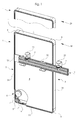
- FIG. 1 is a perspective view of the hoistway device according to the invention with a holding device 2 is shown.
- the lifting wall device has a lifting wall 1, which is height-adjustable via the first guide device 3, so that the lifting wall 1 can be transferred from the illustrated first position EP into a second position ZP and back.
- the holding device 2 is formed in this embodiment as an extruded profile made of metal and has two spaced-apart holding elements 21. On the holding elements 21 fasteners 7 are arranged, which make it possible to fix the hoistway device according to the invention, for example, to a table top, not shown here.
- the holding device 2 is further formed in this embodiment, that it has a receptacle to receive the holding member 52 of the second guide means 5, not shown here fixing.
- the first guide device 3 has in this embodiment, two oppositely arranged guide elements 31.
- the guide elements 31 of the first guide device 3 are connected to each other in this embodiment via the first profile element 11 and the connecting element 9.
- the guide element 31 of the first guide device 3 and the first profile element 11 are arranged via the connecting element 9, forming a frame.
- the lifting wall 1 of the lifting wall device according to the invention is formed in this embodiment so that the opening of the frame formed from the guide element 31 of the first guide device 3, the first profile element 11 and the connecting element 9 is closed by a cover 4.
- the lifting wall 1 is fixed to the holding device 2 and can now be transferred by simply moving up or down from a first position EP in a second position ZP and back.
- the holding element 52 of the second guide device 5 remains fixed and thus guides the path of the lifting wall 1 from the first position EP to a second position ZP and back as a result of the arrangement in the guide element 31 of the first guide device 3.
- a holding element 52 is shown, which is arranged in the interior of the lifting wall 1 on the second guide device 5, which is not visible here.
- the energy accumulator 6 is arranged in this embodiment so that it is fixed to the first guide device 3, with the second guide device 5, not shown, in operative connection.
- the hoistway device has a corner connector 14 which frictionally secures the first profile element 11 with the guide element 31 of the first guide device 3, covering the connecting element 9 on the inside.
- the corner connector 14 is fixed in this embodiment via a fastening element 7 on the connecting element 9.
- the lifting device according to the invention is further formed in this embodiment that the flat visible sides of the lifting wall 1 are closed by a cover 4, which in this embodiment has a sound-absorbing material as part of a soundproofing element, which is also arranged on the non-viewing side.
- the lifting wall 1 has a closed cavity in which the non-visible second guide device 5 is arranged.
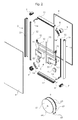
- FIG. 2 is a perspective detail view of another lifting device according to the invention shown.
- an additional profile 32 is arranged, which serves to receive the cover 4 fixing.
- the additional profile 32 is arranged on the guide element 31 of the first guide device 3.
- the guide elements 31 of the first guide device 3 are connected in this embodiment via connecting elements 9 with the first profile element 11, forming a total frame.
- an additional corner connector 14 is positioned at all four corners, which stabilizes the frame via fastening means known per se with the connecting element 9.
- the lifting device according to the invention further comprises a second guide means 5, which in this embodiment has two oppositely arranged guide elements 51.
- the guide elements 51 of the guide device 5 are connected to each other in this embodiment by two second profile elements 12.
- the guide elements 51 of the second guide device 5 furthermore have a holding element 52 in this exemplary embodiment.
- the second guide device 5 is further designed such that it has a spacer element 13 which is fixed to at least one second profile element 12.
- the spacer element 13 in this embodiment has a length of about 463 mm, which corresponds to the path of the lifting wall 1 from the first position EP to the second position ZP and back.
- the second guide device 5 is further formed in this embodiment, that on the guide member 51 relative to the holding member 52, a sliding member 10 is arranged.
- the guide member 51 of the second guide device 5 each have two oppositely arranged sliding elements 10, which again lead to a simpler and possible with very little effort movement of the lifting wall 1.
- the hoistway device according to the invention has in this embodiment, two force accumulator 6, which are fixed opposite one another to the second guide device 5 and are in operative connection with the first guide device 3.
- the second guide device 5 Upon proper movement of the hoistway device according to the invention from a first position EP to a second position ZP and back, the second guide device 5 remains in its position and the guide elements 31 of the first guide device 3 are moved over the sliding elements 10 of the second guide device 5.
- the energy accumulator 6 is fixed to the first guide device 3 via the housing 61 and that the spring element 62 is fixed to the guide element 31 of the second guide device 5.
- the lifting device according to the invention further comprises in each case a fixing element 8 arranged on the first profile element 11 in this exemplary embodiment.
- the fixing element 8 is arranged centrally on the first profile element 11 and positioned so that in the assembled state of the lifting wall 1, the fixing element 8 is arranged exactly opposite the free end of the spacer element 13.
- the spacer element 13 is made in this embodiment as a round rod made of a ferromagnetic material and upon movement of the lifting device according to the invention from a first position EP to a second position ZP and back takes place upon contact of a free end of the spacer element 13 with the fixing element 8 an audible lock.
- the fixing element 8 is, for example, formed as a permanent magnet.
- the guide elements 31, 51 of the guide device 3, 5 are interconnected via at least one profile element 11, 12.
- the guide elements 31 of the first guide device 3 and the first profile elements 11 are formed so that they can be connected at their free ends via a respective corner connector 14 without the additional connecting elements 9 is used.
- the free ends of the guide elements 31 of the first guide device 3 and the first profile elements 11 are formed either at right angles or mitred at an angle of about 45 °.
- the cover 4 of the lifting device according to the invention can be fixed in the additional profile 32 of the first guide device 3 but also in the guide member 31 of the first guide device 3.
- the lifting wall device according to the invention can also be designed so that in particular the first guide device 3 and the second guide device 5 are made of a metallic and / or polymeric and / or ceramic material.
- the connecting elements 9 and the corner connectors 14 can also be made of a metallic and / or a polymeric material.
- the cover 4 is made in this embodiment of fabric and fixed by suitable fasteners on the first guide device 3 and the first profile elements 11.
- the cover element 4 of the lifting wall device according to the invention may comprise at least one sound-absorbing and / or sound-absorbing material as part of a soundproofing element, here are used fabric, acoustic fleece, felt, films, gypsum or plasterboard foams, Mineralmaschinem and the like.
- the energy accumulator 6 is formed in this embodiment as a rolling tension spring and has a housing formed as a drum 61, which is circular.
- a peripheral edge 63 is arranged, between which the spring element 62 is positioned.
- the trained as a drum housing 61 of the energy accumulator 6 has in this embodiment, an opening 64, which is seconded centrally in the housing 61.
- the housing 61 with a known fastening means rotatable, for example.
- the second guide device 5 can be arranged on the second guide device 5 .
- the spring element 62 arranged on the housing 61 of the energy store 6 designed as a drum is unrolled or rolled up and thus leads to a smooth and simple movement the lifting wall 1.
- the spring element 62 of the energy accumulator 6 is made in this embodiment of a band-shaped metal, a spring steel such as the X12 CrNi 17-7.
- the material of the spring element 62 has a material-related, inherent average force of about 15 to 50 N, preferably 20 to 35 N.
- the spring element 62 of the energy accumulator 6 has a developed, stretched length of about 200 to 1200, preferably 400 to 800 mm.
- the energy accumulator 6 can be dimensioned in each case such that the hoistway device according to the invention can be transferred from a first position EP to a second position ZP and back, in a dimension of approximately 100 to 1,200 mm, preferably 250 to 800 mm.
- the spring element 62 of the force accumulator 6 also has at its free end openings 65 with which it can be fixed either to the first guide device 3 or alternatively to the second guide device 5.
- the designed as a drum housing 61 is made for example of a polymeric material such as, polyamide.
- the hoistway device according to the invention in each case two oppositely arranged, designed as a roll-on spring energy accumulator 6.
- the energy accumulator 6 is formed as a gas spring or as known per se coil spring, coil spring and the like.
- FIG. 3 is a perspective detail view of another lifting device according to the invention shown.
- an additional profile 32 is arranged, which serves to receive the cover 4 fixing.
- the additional profile 32 is arranged on the guide element 31 of the first guide device 3.
- the guide elements 31 of the first guide device 3 are connected in this embodiment via connecting elements 9 with the first profile element 11, forming a total frame.
- an additional corner connector 14 is positioned at all four corners, which stabilizes the frame via fastening means known per se with the connecting element 9.
- the lifting device according to the invention further comprises a second guide means 5, which in this embodiment has two oppositely arranged guide elements 51.
- the guide elements 51 of the guide device 5 are connected to each other in this embodiment by two second profile elements 12.
- the guide elements 51 of the second guide device 5 furthermore have a holding element 52 in this exemplary embodiment.
- the second guide device 5 is designed such that it has a spacer element 13 which is fixed to at least one second profile element 12.
- the spacer element 13 in this embodiment has a length of about 450 mm, which corresponds to the path of the lifting wall 1 from the first position EP to the second position ZP and back.
- the second guide device 5 is furthermore designed such that a sliding element 10 is arranged on the guide element 51 relative to the holding element 52.
- the sliding element 10 of the second guide device 5 enables a simple and frictionless movement between the guide element 51 of the second guide device and the guide element 31 of the first guide device 3.
- the guide member 51 of the second guide device 5 each have two oppositely arranged sliding elements 10, which again lead to a simpler and possible with very little effort movement of the lifting wall 1.
- the hoistway device has in this embodiment, three power storage 6, which are fixed opposite each other on the second guide device 5 and are in operative connection with the first guide device 3.
- a first energy store 6 is fixed to the holding element 52 in this embodiment.
- Two other power storage 6 are fixed directly opposite each other on the second profile element 12 of the two guide devices 5.
- the energy accumulators 6 are in operative connection with a third profile element 15.
- the third profile element 15 is fixed in this embodiment on the first profile element 11.
- the second guide device 5 Upon proper movement of the hoistway device according to the invention from a first position EP to a second position ZP and back, the second guide device 5 remains in its position and the guide elements 31 of the first guide device 3 are moved over the sliding elements 10 of the second guide device 5.
- the energy accumulator 6 is fixed to the first guide device 3 via the housing 61 and that the spring element 62 is fixed to the guide element 31 of the second guide device 5.
- the lifting device according to the invention further comprises in each case a fixing element 8 arranged on the first profile element 11 in this exemplary embodiment.
- the fixing element 8 is arranged centrally on the first profile element 11 and positioned so that in the assembled state of the lifting wall 1, the fixing element 8 is arranged exactly opposite the free end of the spacer element 13.
- the spacer element 13 is made in this embodiment as a round rod made of a ferromagnetic material and upon movement of the lifting device according to the invention from a first position EP to a second position ZP and back takes place upon contact of a free end of the spacer element 13 with the fixing element 8 an audible lock.
- the fixing element 8 is, for example, formed as a permanent magnet.
- the guide elements 31, 51 of the guide device 3, 5 are interconnected via at least one profile element 11, 12.
- the guide elements 31 of the first guide device 3 and the first profile elements 11 are formed so that they can be connected at their free ends via a respective corner connector 14 without the additional connecting elements 9 is used.
- the free ends of the guide elements 31 of the first guide device 3 and the first profile elements 11 are formed either at right angles or mitred at an angle of about 45 °.
- the cover 4 of the lifting device according to the invention is in the additional profile 32 of the first guide device 3 and / or in the guide member 31 of the first guide device 3 fixed.
- the lifting wall device according to the invention can also be designed so that in particular the first guide device 3 and the second guide device 5 are made of a metallic and / or polymeric and / or ceramic material.
- the connecting elements 9 and the corner connectors 14 can also be made of a metallic and / or a polymeric material.
- the cover 4 is made in this embodiment of fabric and fixed by suitable fasteners on the first guide device 3 and the first profile elements 11.
- the cover element 4 of the lifting wall device according to the invention may comprise at least one sound-damping and / or sound-absorbing material as part of a soundproofing element, here are used fabric, acoustic fleece, felt, films, gypsum or plasterboard foams, Mineralmaschinem and the like.
Landscapes
- Lift-Guide Devices, And Elevator Ropes And Cables (AREA)
- Types And Forms Of Lifts (AREA)
Abstract
Description
- Die Erfindung betrifft eine Hebewandvorrichtung mit wenigstens einer Hebewand, die über wenigstens zwei Führungsvorrichtungen höhenverstellbar ist, so dass die Hebewand von einer ersten Position (EP) in eine zweite Position (ZP) und zurück überführbar ist, sowie wenigstens einem Kraftspeicher.
- Derartige Hebewandvorrichtungen sind bereits aus dem Stand der Technik bekannt.
- So beschreibt die
DE 10 2006 034 332 B4 einen Büroarbeitsplatz, insbesondere einen Bildschirmarbeitsplatz mit einer daran angeordneten Hebewandvorrichtung. Diese umfasst eine Hebewand, die höhenverstellbar an einer Tischplatte angeschlossen und zwischen einer abgesenkten Stellung und eine erhabene Stellung höhenverstellbar ist. Diese Hebewandvorrichtung ist fest mit dem Tisch montiert und kann nicht an die Bedürfnisse des an diesem Tisch arbeitenden Menschen in Bezug auf die Sicht- und Lichtverhältnisse bzw. auch die Akustik angepasst werden. Weiterhin ist die Verlegbarkeit von Anschlussleitungen für Bürokommunikationsmittel wie Telefonkabel, Computerkabel und dergleichen von und zu dem Bürotisch stark eingeschränkt, das sämtliche Leitungen immer um die Hebewand herumgeführt werden müssen. - Ebenfalls nachteilig ist der komplizierte mechanische Aufbau mit der massiven Stellstange und der sich daran abwälzenden Führungsrolle in Verbindung mit der zusätzlich angeordneten Druckfeder, insbesondere der Gasdruckfeder.
- Hier setzt die Erfindung ein, die sich die Aufgabe gestellt hat, die Nachteile des bekannten Standes der Technik zu überwinden und eine Hebewandvorrichtung aufzuzeigen, die kostengünstig und wirtschaftlich herstellbar ist, die einfach und mit geringem Kraftaufwand höhenverstellbar sowie leicht an Tischen, Schränken und dergleichen montierbar ist.
- Gelöst wird diese Aufgabe mit einer Hebewandvorrichtung gemäß den Merkmalen des Anspruches 1. Weitere vorteilhafte Ausgestaltungen sind in den Unteransprüchen beschrieben.
- Es hat sich überraschend herausgestellt, dass eine Hebewandvorrichtung mit wenigstens einer Hebewand, die über wenigstens zwei Führungsvorrichtungen höhenverstellbar ist, so dass die Hebewand von einer ersten Position EP in eine zweite Position ZP und zurück überführbar ist, sowie wenigstens einem Kraftspeicher sich dadurch auszeichnet, dass die erste Führungsvorrichtung an der zweiten Führungsvorrichtung, mit dieser in Wirkverbindung stehend angeordnet ist, das der Kraftspeicher an wenigstens einer Führungsvorrichtung mit der anderen Führungsvorrichtung in Wirkverbindung stehend, fixiert ist und das die zweite Führungsvorrichtung wenigstens ein Halteelement aufweist. Hierdurch kann vorteilhafterweise die Hebewand flexibel in der Höhe verstellt werden, ohne das zusätzliche Halte- bzw. Rastelemente erforderlich sind.
- Weiterhin ist es vorteilhafterweise möglich, neben der einfachen mechanischen Beweglichkeit der erfindungsgemäßen Hebewandvorrichtung diese hinsichtlich ihrer Breite bzw. Größe allen Anforderungen gemäß anzupassen und so über beispielsweise geeignete Halteeinrichtungen diese an Tischen aber auch an Schränken und ähnlichen Öffnungen zu positionieren und in bestimmungsgemäßer Weise zu nutzen.
- Dabei hat es sich weiterhin als vorteilhaft herausgestellt, dass der Kraftspeicher an der ersten Führungseinrichtung, mit der zweiten Führungseinrichtung in Wirkverbindung stehend, fixiert ist.
- Weiterhin vorteilhaft bei der erfindungsgemäßen Hebewandvorrichtung ist es, dass der Kraftspeicher an der zweiten Führungseinrichtung, mit der ersten Führungseinrichtung in Wirkverbindung stehend, fixiert ist.
- Hierdurch kann durch unterschiedliche Dimensionierung der Kraftspeicher eine kostengünstige und wirtschaftliche Herstellung der erfindungsgemäßen Hebewandvorrichtung realisiert werden, wobei diese beispielsweise an einem Tisch befestigt, sehr einfach von einer ersten Position EP in eine zweite Position ZP und zurück überführbar ist, ohne das hierzu ein hoher Kraftaufwand bzw. zusätzliche elektrische Unterstützungselemente erforderlich sind.
- Es hat sich weiterhin als vorteilhaft herausgestellt, dass der Kraftspeicher dabei als Rollzugfeder, Gasdruckfeder, Spiralfeder, Schraubenfeder und dergleichen ausgebildet ist. Hierdurch lässt sich je nach Größe und Gewicht der Hebewand problemlos der Kraftspeicher so dimensionieren, dass bei der erfindungsgemäßen Hebewandvorrichtung die Hebewand leicht und mit geringem ohne Kraftaufwand von einer ersten Position EP in eine zweite Position ZP und zurück höhenverstellbar überführbar ist.
- In einer besonders vorteilhaften Ausgestaltung der erfindungsgemäßen Hebewandvorrichtung ist der Kraftspeicher als sog. Rollzugfeder ausgebildet.
- Diese Rollzugfeder weist ein Gehäuse auf, in dem ein bandförmiges Federelement einer bestimmten Länge in einem bestimmten Werkstoff angeordnet ist.
- Dieses Federelement ist dabei mit seinem einem freien Ende am Gehäuse angeordnet, während das zweite freie Ende an der ersten Führungsvorrichtung bzw. der zweiten Führungsvorrichtung der erfindungsgemäßen Hebewandvorrichtung fixiert ist.
- Das Gehäuse des als Rollzugfeder ausgebildeten Kraftspeichers ist dabei so ausgebildet, dass es zentrisch eine Durchgangsbohrung aufweist, durch die ein Befestigungselement durchführbar ist und so der Kraftspeicher drehbar an der ersten Führungsvorrichtung bzw. der zweiten Führungsvorrichtung der erfindungsgemäßen Hebewandvorrichtung anbringbar ist.
- Beim bestimmungsgemäßen Einsatz der erfindungsgemäßen Hebewandvorrichtung bei der die Hebewand von einer ersten Position EP in eine zweite Position ZP und zurück überführbar ist, wird dabei der als Rollzugfeder ausgebildete Kraftspeicher, der fest an der ersten Führungsvorrichtung oder der zweiten Führungsvorrichtung angeordnet ist, in Rotationsbewegung versetzt, da das freie Ende des Federelements an der anderen Führungsvorrichtung angeordnet ist. Durch die Bewegung der Hebewand von einer ersten Position EP in eine zweite Position ZP und zurück wird somit das Federelement der als Kraftspeicher ausgebildeten Rollzugfeder auf- und abgewickelt und bremst so die Bewegung der Hebewand der erfindungsgemäßen Hebewandvorrichtung.
- In einer weiteren vorteilhaften Ausgestaltung der erfindungsgemäßen Hebewandvorrichtung weist die Führungseinrichtung wenigstens zwei einander gegenüberliegend angeordnete Führungselemente auf. In dieser vorteilhaften Ausgestaltung kann sowohl die erste Führungsvorrichtung und / oder die zweite Führungsvorrichtung gegenüberliegend angeordnete Führungselemente aufweisen. Dies ist abhängig von der Geometrie bzw. der Dimensionierung der Hebewand.
- Es hat sich weiterhin als vorteilhaft herausgestellt, dass bei der erfindungsgemäßen Hebewandvorrichtung die Führungselemente der Führungsvorrichtungen über wenigstens ein Profilelement miteinander verbunden sind. Diese Maßnahme führt einerseits zu einer kostengünstigen und wirtschaftlichen Herstellung der erfindungsgemäßen Hebewandvorrichtung und andererseits zu einer ausreichenden Stabilisierung und hohen Festigkeit der Hebewand.
- Dabei hat sich ebenfalls vorteilhafterweise herausgestellt, dass sich die erfindungsgemäße Hebewandvorrichtung weiterhin dadurch auszeichnet, dass das Führungselement der ersten Führungsvorrichtung über wenigstens ein Verbindungselement mit dem Profilelement verbunden ist. Dies kann vorteilhafterweise so realisiert werden, dass das Führungselement der ersten Führungsvorrichtung und das Profilelement über das Verbindungselement, einen Rahmen bildend, angeordnet sind. Dies lässt sich sowohl kostengünstig als auch wirtschaftlich realisieren und bewirkt eine ausreichende Stabilisierung bei gleichbleibend geringem Gewicht der erfindungsgemäßen Hebewandvorrichtung.
- Ebenfalls vorteilhaft bei der erfindungsgemäßen Hebewandvorrichtung ist, dass das Führungselement der ersten Führungsvorrichtung über wenigstens ein Gleitelement vom Führungselement der zweiten Führungsvorrichtung beabstandet angeordnet ist. Dies führt noch einmal zu einem verbesserten Handling insbesondere beim Überführen der Hebewand von einer ersten Position (EP) in eine zweite Position (ZP) und zurück mit einem nochmals geringerem Kraftaufwand.
- Dabei hat es sich weiterhin als vorteilhaft erwiesen, dass das Gleitelement am Führungselement der ersten Führungsvorrichtung und / oder am Führungselement der zweiten Führungsvorrichtung fixiert ist. Hierdurch lässt sich je nach Dimensionierung der Gleitelemente eine schnelle und kostengünstige Montage an der jeweiligen Führungsvorrichtung realisieren.
- Die erfindungsgemäße Hebewandvorrichtung ist weiterhin so ausgebildet, dass die Hebewand wenigstens einen offen und / oder einen geschlossenen Hohlraum aufweist. Weiterhin vorteilhaft bei der erfindungsgemäßen Hebewandvorrichtung ist es, dass die Hebewand an wenigstens einer Seite ein Abdeckelement aufweist.
- Dieses Abdeckelement, welches kostengünstig herstellbar und beispielsweise aus Stoff, Leder, Papier, Filz, Vlies, Folien, Gips, Schaumstoff und dergleichen hergestellt ist, verleiht der erfindungsgemäßen Hebewandvorrichtung ein ansprechendes und dem jeweiligen Nutzer auch anpassbares Äußeres bzw. Design.
- Es hat sich weiterhin als äußerst vorteilhaft bei der erfindungsgemäßen Hebewandvorrichtung erwiesen, dass das Abdeckelement wenigstens ein schalldämpfendes und / oder schallabsorbierendes Material als Teil eines Schallschutzelementes an und / oder in der Hebewand angeordnet, aufweist.
- Weiterhin kann ebenfalls in den Hohlraum der Hebewand ein weiterer Schallabsorber in Form von Akustikschaum, Polyesterfaserplatten, Gipsplatten und dgl. angeordnet sein, so dass die Hebewand der erfindungsgemäßen Hebewandvorrichtung schalldämpfend bzw. schallabsorbierend ausgebildet ist.
- Ein weiterer Vorteil der erfindungsgemäßen Hebewandvorrichtung besteht darin, dass die zweite Führungsvorrichtung wenigstens ein Distanzelement aufweist. Dieses Distanzelement ist vorteilhafterweise so ausgebildet, dass es durch seine Anordnung an der zweiten Führungsvorrichtung so dimensionierbar ist, dass dies den Weg der Hebewand von der erster Position EP bis zur zweiten Position EP und zurück definiert. Das Distanzelement ist dabei vorteilhafterweise so in seiner Länge ausgebildet, dass es mit seinem einen freien Ende die erste Position EP und mit seinem zweiten freien Ende die zweite Position ZP der Hebewand definiert.
- In einer weiteren vorteilhaften Ausgestaltung der erfindungsgemäßen Hebewandvorrichtung weist die erste Führungsvorrichtung und / oder das Profilelement wenigstens ein Fixierelement auf. Dieses Fixierelement dient dazu, die Hebewand in ihrer ersten Position EP und / oder in ihrer zweiten Position ZP zu fixieren. Dabei kann das Fixierelement bspw. als sogenannter Dauermagnet ausgebildet sein.
- Ebenfalls vorteilhaft bei der erfindungsgemäßen Hebewandvorrichtung ist, dass das Distanzelement der zweiten Führungsvorrichtung mit wenigstens einem Fixierelement der ersten Führungsvorrichtung und / oder des Profilelements in Wirkverbindung steht.
- Hierdurch kann eine zusätzliche Fixierung in der ersten Position EP und / oder in der zweiten Position ZP der Hebewand realisiert werden.
- In einer weiteren Ausführungsform der erfindungsgemäßen Hebewandvorrichtung ist die Hebewand an wenigstens einer Halteeinrichtung angeordnet. Dies ist vorteilhafterweise insbesondere bei der Befestigung der Hebewandvorrichtung beispielsweise an einem Tisch einfach und kostengünstig.
- Dabei hat es sich weiterhin als vorteilhaft herausgestellt, dass bei der erfindungsgemäßen Hebewandvorrichtung die Hebewand über wenigstens zwei Führungsvorrichtungen höhenverstellbar an der Halteeinrichtung angeordnet ist. Die erfindungsgemäße Hebewandvorrichtung lässt sich somit einfach sowohl an einem Tisch aber auch an der Öffnung eines Schrankes und dergleichen an der Halteeinrichtung fixieren und dann von der ersten Position EP in eine zweite Position ZP und zurück überführen.
- Dabei hat es sich insbesondere als vorteilhaft herausgestellt, dass bei der erfindungsgemäßen Hebewandvorrichtung das Halteelement der zweiten Führungsvorrichtung an der Halteeinrichtung fixiert ist. Dies führt einerseits zu einer schnellen, kostengünstigen und nicht sichtbaren Fixierung an der Halteeinrichtung und andererseits zu einem leichten und mit geringem Kraftaufwand möglichen Bewegen der Hebewand von einer ersten Position EP in eine zweite Position ZP und zurück.
- Die Erfindung soll nun an diesen nicht einschränkenden Ausführungsbeispielen näher beschrieben werden.
- Es zeigen:
- Fig. 1:
- perspektivische Darstellung der erfindungsgemäßen Hebewandvorrichtung mit Halteeinrichtung;
- Fig. 2:
- perspektivische Einzelteildarstellung einer weiteren erfindungsgemäßen Hebewandvorrichtung.
- Fig. 3:
- perspektivische Einzelteildarstellung einer weiteren erfindungsgemäßen Hebewandvorrichtung.
- In der
Fig. 1 ist eine perspektivische Darstellung der erfindungsgemäßen Hebewandvorrichtung mit einer Halteeinrichtung 2 dargestellt. - Die Hebewandvorrichtung weist eine Hebewand 1 auf, die über die ersten Führungseinrichtung 3 höhenverstellbar ist, so dass die Hebewand 1 von der dargestellten ersten Position EP in eine zweite Position ZP und zurück überführbar ist.
- Die Halteeinrichtung 2 ist in diesem Ausführungsbeispiel als stranggepresstes Profil aus Metall ausgebildet und weist zwei voneinander beabstandet angeordnete Halteelemente 21 auf. An den Halteelementen 21 sind Befestigungselemente 7 angeordnet, die es ermöglichen, die erfindungsgemäße Hebewandvorrichtung beispielsweise an einer hier nicht dargestellten Tischplatte zu fixieren.
- Die Haltevorrichtung 2 ist in diesem Ausführungsbeispiel weiterhin so ausgebildet, dass sie eine Aufnahme aufweist, um das Halteelement 52 der hier nicht dargestellten zweiten Führungseinrichtung 5 fixierend aufzunehmen.
- Die erste Führungsvorrichtung 3 weist in diesem Ausführungsbeispiel zwei einander gegenüberliegend angeordnete Führungselemente 31 auf.
- Die Führungselemente 31 der ersten Führungsvorrichtung 3 sind in diesem Ausführungsbeispiel über das erste Profilelement 11 sowie das Verbindungselement 9 miteinander verbunden.
- Das Führungselement 31 der ersten Führungsvorrichtung 3 und das erste Profilelement 11 sind über das Verbindungselement 9, einen Rahmen bildend, angeordnet.
- Die Hebewand 1 der erfindungsgemäßen Hebewandvorrichtung ist in diesem Ausführungsbeispiel so ausgebildet, dass die Öffnung des aus dem Führungselement 31 der ersten Führungsvorrichtung 3, des ersten Profilelements 11 und des Verbindungselements 9 gebildeten Rahmens durch ein Abdeckelement 4 verschlossen ist.
- Über das Halteelement 52 der nicht dargestellten zweiten Führungsvorrichtung 5 ist die Hebewand 1 an der Halteeinrichtung 2 fixiert und kann nun durch einfaches Hoch- bzw. Runterschieben von einer ersten Position EP in eine zweite Position ZP und zurück überführt werden.
- Hierzu bleibt das Halteelement 52 der nicht dargestellten zweiten Führungsvorrichtung 5 fixiert und führt so durch die Anordnung im Führungselement 31 der ersten Führungsvorrichtung 3 den Weg der Hebewand 1 von der ersten Position EP in eine zweite Position ZP und zurück.
- An dem Führungselement 31 der ersten Führungsvorrichtung 3 ist jeweils ein Halteelement 52 dargestellt, welches im Inneren der Hebewand 1 an der zweiten Führungsvorrichtung 5, die hier nicht sichtbar ist, angeordnet ist.
- Im linken unteren Teil der Hebewand 1 ist ein Teilschnitt dargestellt, in dem ein Kraftspeicher 6 dargestellt ist.
- Der Kraftspeicher 6 ist in diesem Ausführungsbeispiel so angeordnet, dass er an der ersten Führungsvorrichtung 3, mit der nicht dargestellten zweiten Führungsvorrichtung 5 in Wirkverbindung stehend, fixiert ist.
- In diesem Ausführungsbeispiel weist die erfindungsgemäße Hebewandvorrichtung einen Eckverbinder 14 auf, der das erste Profilelement 11 mit dem Führungselement 31 der ersten Führungsvorrichtung 3 kraftschlüssig, das Verbindungselement 9 innen überdeckend, fixiert.
- Der Eckverbinder 14 ist in diesem Ausführungsbeispiel über ein Befestigungselement 7 am Verbindungselement 9 fixiert.
- Die erfindungsgemäße Hebewandvorrichtung ist in diesem Ausführungsbeispiel weiterhin so ausgebildet, dass die flächigen Sichtseiten der Hebewand 1 durch ein Abdeckelement 4 verschlossen sind, welches in diesem Ausführungsbeispiel ein schallabsorbierendes Material als Teil eines Schallschutzelementes aufweist, welches auch auf der Nichtsichtseite entsprechend angeordnet ist.
- Zwischen dem sichtbaren Abdeckelement 4 und dem nicht sichtbaren Abdeckelement weist die Hebewand 1 einen geschlossenen Hohlraum auf, in dem die nicht sichtbare zweite Führungsvorrichtung 5 angeordnet ist.
- In der
Fig. 2 ist eine perspektivische Einzelteildarstellung einer weiteren erfindungsgemäßen Hebewandvorrichtung dargestellt. - Diese weist zwei einander gegenüberliegend angeordnete Führungselemente 31 der ersten Führungsvorrichtung 3 auf.
- An den Führungselementen 31 der ersten Führungsvorrichtung 3 ist ein Zusatzprofil 32 angeordnet, welches dazu dient, die Abdeckvorrichtung 4 fixierend aufzunehmen.
- Das Zusatzprofil 32 ist dabei am Führungselement 31 der ersten Führungsvorrichtung 3 angeordnet.
- Die Führungselemente 31 der ersten Führungsvorrichtung 3 sind in diesem Ausführungsbeispiel über Verbindungselemente 9 mit dem ersten Profilelement 11, insgesamt einen Rahmen bildend, verbunden.
- Zur besseren Fixierung und Stabilisierung ist dabei an allen vier Ecken ein zusätzlicher Eckverbinder 14 positioniert, der über an sich bekannte Befestigungsmittel mit dem Verbindungselement 9 den Rahmen stabilisierend, fixiert ist.
- Die erfindungsgemäße Hebewandvorrichtung weist weiterhin eine zweite Führungseinrichtung 5 auf, die in diesem Ausführungsbeispiel zwei einander gegenüberliegend angeordnete Führungselemente 51 aufweist.
- Die Führungselemente 51 der Führungsvorrichtung 5 sind in diesem Ausführungsbeispiel durch zwei zweite Profilelemente 12 miteinander verbunden.
- Die Führungselemente 51 der zweiten Führungsvorrichtung 5 weisen weiterhin in diesem Ausführungsbeispiel jeweils ein Halteelement 52 auf.
- Die zweite Führungsvorrichtung 5 ist weiterhin so ausgebildet, dass sie ein Distanzelement 13 aufweist, welches an wenigstens einem zweiten Profilelement 12 fixiert ist.
- Das Distanzelement 13 weist in diesem Ausführungsbeispiel eine Länge von etwa 463 mm auf, welche den Weg der Hebewand 1 von der ersten Position EP in die zweite Position ZP und zurück entspricht.
- Die zweite Führungsvorrichtung 5 ist in diesem Ausführungsbeispiel weiterhin so ausgebildet, dass am Führungselement 51 gegenüber dem Halteelement 52 ein Gleitelement 10 angeordnet ist.
- Durch das Gleitelement 10 der zweiten Führungsvorrichtung 5 ist eine einfache und möglichst reibungsfreie Bewegung zwischen dem Führungselement 51 der zweiten Führungsvorrichtung und dem Führungselement 31 der ersten Führungsvorrichtung 3 möglich.
- In diesem Ausführungsbeispiel weist das Führungselement 51 der zweiten Führungsvorrichtung 5 jeweils zwei einander gegenüberliegend angeordnete Gleitelemente 10 auf, welche nochmals zu einer einfacheren und mit sehr geringem Kraftaufwand möglichen Bewegung der Hebewand 1 führen.
- Die erfindungsgemäße Hebewandvorrichtung weist in diesem Ausführungsbeispiel zwei Kraftspeicher 6 auf, die einander gegenüberliegend an der zweiten Führungsvorrichtung 5 fixiert und mit der ersten Führungsvorrichtung 3 in Wirkverbindung stehen.
- Bei bestimmungsgemäßer Bewegung der erfindungsgemäßen Hebewandvorrichtung von einer ersten Position EP in eine zweite Position ZP und zurück verbleibt die zweite Führungsvorrichtung 5 in ihrer Position und die Führungselemente 31 der ersten Führungsvorrichtung 3 werden über die Gleitelemente 10 der zweiten Führungsvorrichtung 5 bewegt. Es liegt jedoch auch im Rahmen der Erfindung, dass der Kraftspeicher 6 an der ersten Führungsvorrichtung 3 über das Gehäuse 61 fixiert ist und dass das Federelement 62 am Führungselement 31 der zweiten Führungsvorrichtung 5 fixiert ist.
- Die erfindungsgemäße Hebewandvorrichtung weist in diesem Ausführungsbeispiel weiterhin jeweils ein am ersten Profilelement 11 angeordnetes Fixierelement 8 auf.
- Das Fixierelement 8 ist dabei mittig am ersten Profilelement 11 angeordnet und so positioniert, dass im zusammengebauten Zustand der Hebewand 1 das Fixierelement 8 genau gegenüber dem freien Ende des Distanzelementes 13 angeordnet ist.
- Das Distanzelement 13 ist in diesem Ausführungsbeispiel als Rundstab aus einem ferromagnetischen Werkstoff hergestellt und bei einer Bewegung der erfindungsgemäßen Hebewandvorrichtung von einer ersten Position EP in eine zweite Position ZP und zurück erfolgt bei Kontakt eines freien Endes des Distanzelementes 13 mit dem Fixierelement 8 eine hörbare Arretierung. Das Fixierelement 8 ist dabei bspw. als Dauermagnet ausgebildet.
- Es liegt weiterhin im Rahmen der Erfindung, dass die Führungselemente 31, 51 der Führungsvorrichtung 3, 5 über wenigstens ein Profilelement 11, 12 miteinander verbunden sind. In dieser Ausführungsform sind die Führungselemente 31 der ersten Führungsvorrichtung 3 sowie die ersten Profilelemente 11 so ausgebildet, dass sie an ihren freien Enden über jeweils einen Eckverbinder 14 miteinander verbindbar sind, ohne das zusätzliche Verbindungselemente 9 zum Einsatz kommt.
- Die freien Enden der Führungselemente 31 der ersten Führungsvorrichtung 3 sowie der ersten Profilelemente 11 sind dabei entweder rechtwinklig oder auf Gehrung in einem Winkel von etwa 45° ausgebildet.
- Das Abdeckelement 4 der erfindungsgemäßen Hebewandvorrichtung kann dabei im Zusatzprofil 32 der ersten Führungsvorrichtung 3 aber auch in dem Führungselement 31 der ersten Führungsvorrichtung 3 fixiert werden.
- Dabei kann die erfindungsgemäße Hebewandvorrichtung auch so ausgebildet sein, dass insbesondere die erste Führungsvorrichtung 3 sowie auch die zweite Führungsvorrichtung 5 aus einem metallischen und / oder polymeren und / oder keramischen Werkstoff hergestellt sind.
- Die Verbindungselemente 9 sowie die Eckverbinder 14 können dabei ebenfalls aus einem metallischen und / oder einen polymeren Werkstoff hergestellt sein.
- Das Abdeckelement 4 ist in diesem Ausführungsbeispiel aus Stoff hergestellt und über geeignete Befestigungselemente an der ersten Führungsvorrichtung 3 sowie den ersten Profilelementen 11 fixiert.
- Das Abdeckelement 4 der erfindungsgemäßen Hebewandvorrichtung kann dabei wenigstens ein schalldämpfendes und / oder schallabsorbierendes Material als Teil eines Schallschutzelementes aufweisen, hierbei kommen zum Einsatz Stoff, Akustikvlies, Filz, Folien, Gips bzw. Gipsplatten Schaumstoffe, Mineralfaserm und dgl.
- In der
Fig. 2 unten rechts ist der Kraftspeicher 6 nochmals im Detail herausgezogen und größer dargestellt. - Der Kraftspeicher 6 ist in diesem Ausführungsbeispiel als Rollzugfeder ausgebildet und weist ein als Trommel ausgebildetes Gehäuse 61 auf, welches kreisförmig ist.
- An den Seiten des als Trommel ausgebildeten Gehäuses 61 ist jeweils ein umlaufender Rand 63 angeordnet, zwischen dem das Federelement 62 positioniert ist.
- Das als Trommel ausgebildete Gehäuse 61 des Kraftspeichers 6 weist in diesem Ausführungsbeispiel eine Öffnung 64 auf, welche zentrisch im Gehäuse 61 abgeordnet ist. Über die Öffnung 64 ist das Gehäuse 61 mit einem bekannten Befestigungsmittel drehbar bspw. an der zweiten Führungsvorrichtung 5 anordenbar.
- Je nach der Richtung der Bewegung der erfindungsgemäßen Hebewandvorrichtung von einer ersten Position EP in eine zweite Position ZP und zurück wird dabei das auf dem als Trommel ausgebildeten Gehäuse 61 des Kraftspeichers 6 angeordnete Federelement 62 abgerollt bzw. aufgerollt und führt so zu einer leichtgängigen und einfachen Bewegung der Hebewand 1.
- Das Federelement 62 des Kraftspeichers 6 ist in diesem Ausführungsbeispiel aus einem bandförmigen Metall, einem Federstahl wie beispielsweise dem X12 CrNi 17-7 hergestellt. Der Werkstoff des Federelements 62 weist eine materialbedingte, immanente mittlere Kraft von etwa 15 bis 50 N, vorzugsweise 20 bis 35 N auf.
- Das Federelement 62 des Kraftspeichers 6 weist dabei eine abgewickelte, gestreckte Länge von etwa 200 bis 1.200, bevorzugt 400 bis 800 mm auf.
- Durch diese vorteilhafte Ausgestaltung kann der Kraftspeicher 6 jeweils so dimensioniert werden, dass die erfindungsgemäße Hebewandvorrichtung von einer ersten Position EP in eine zweite Position ZP und zurück überführbar ist, in einer Dimension von etwa 100 bis 1.200 mm, vorzugsweise 250 bis 800 mm.
- Das Federelement 62 des Kraftspeichers 6 weist weiterhin an seinem freien Ende Öffnungen 65 auf mit denen es entweder an der ersten Führungsvorrichtung 3 oder alternativ auch an der zweiten Führungsvorrichtung 5 fixierbar ist.
- Das als Trommel ausgebildete Gehäuse 61 ist beispielsweise aus einem polymeren Werkstoff wie bspw. Polyamid hergestellt.
- In diesem Ausführungsbeispiel weist die erfindungsgemäße Hebewandvorrichtung jeweils zwei einander gegenüberliegend angeordnete, als Rollzugfeder ausgebildete Kraftspeicher 6 auf.
- Es liegt auch im Rahmen der Erfindung, dass nur ein als Rollzugfeder ausgebildeter Kraftspeicher 6 oder bei größeren erfindungsgemäßen Hebewandvorrichtungen auch mehrere als Rollzugfeder ausgebildete Kraftspeicher 6 zum Einsatz kommen.
- Es liegt aber auch weiterhin im Rahmen der Erfindung, dass der Kraftspeicher 6 als Gasdruckfeder oder auch als an sich bekannte Spiralfeder, Schraubenfeder und dergleichen ausgebildet ist.
- Hierdurch sind bei der erfindungsgemäßen Hebewandvorrichtung verschieden dimensionierte Hebewände 1 mit der entsprechenden Kraft des Kraftspeichers 6 für eine Bewegung von einer ersten Position EP in eine zweite Position ZP und zurück zur Verfügung stellbar.
- In der
Fig. 3 ist eine perspektivische Einzelteildarstellung einer weiteren erfindungsgemäßen Hebewandvorrichtung dargestellt. - Diese weist zwei einander gegenüberliegend angeordnete Führungselemente 31 der ersten Führungsvorrichtung 3 auf. An den Führungselementen 31 der ersten Führungsvorrichtung 3 ist ein Zusatzprofil 32 angeordnet, welches dazu dient, die Abdeckvorrichtung 4 fixierend aufzunehmen. Das Zusatzprofil 32 ist dabei am Führungselement 31 der ersten Führungsvorrichtung 3 angeordnet.
- Die Führungselemente 31 der ersten Führungsvorrichtung 3 sind in diesem Ausführungsbeispiel über Verbindungselemente 9 mit dem ersten Profilelement 11, insgesamt einen Rahmen bildend, verbunden.
- Zur besseren Fixierung und Stabilisierung ist dabei an allen vier Ecken ein zusätzlicher Eckverbinder 14 positioniert, der über an sich bekannte Befestigungsmittel mit dem Verbindungselement 9 den Rahmen stabilisierend, fixiert ist.
- Die erfindungsgemäße Hebewandvorrichtung weist weiterhin eine zweite Führungseinrichtung 5 auf, die in diesem Ausführungsbeispiel zwei einander gegenüberliegend angeordnete Führungselemente 51 aufweist. Die Führungselemente 51 der Führungsvorrichtung 5 sind in diesem Ausführungsbeispiel durch zwei zweite Profilelemente 12 miteinander verbunden. Die Führungselemente 51 der zweiten Führungsvorrichtung 5 weisen weiterhin in diesem Ausführungsbeispiel jeweils ein Halteelement 52 auf.
- Die zweite Führungsvorrichtung 5 ist so ausgebildet, dass sie ein Distanzelement 13 aufweist, welches an wenigstens einem zweiten Profilelement 12 fixiert ist.
- Das Distanzelement 13 weist in diesem Ausführungsbeispiel eine Länge von etwa 450 mm auf, welche den Weg der Hebewand 1 von der ersten Position EP in die zweite Position ZP und zurück entspricht.
- Die zweite Führungsvorrichtung 5 ist weiterhin so ausgebildet, dass am Führungselement 51 gegenüber dem Halteelement 52 ein Gleitelement 10 angeordnet ist. Das Gleitelement 10 der zweiten Führungsvorrichtung 5 ermöglicht eine einfache und möglichst reibungsfreie Bewegung zwischen dem Führungselement 51 der zweiten Führungsvorrichtung sowie dem Führungselement 31 der ersten Führungsvorrichtung 3.
- In diesem Ausführungsbeispiel weist das Führungselement 51 der zweiten Führungsvorrichtung 5 jeweils zwei einander gegenüberliegend angeordnete Gleitelemente 10 auf, welche nochmals zu einer einfacheren und mit sehr geringem Kraftaufwand möglichen Bewegung der Hebewand 1 führen.
- Die erfindungsgemäße Hebewandvorrichtung weist in diesem Ausführungsbeispiel drei Kraftspeicher 6 auf, die einander gegenüberliegend an der zweiten Führungsvorrichtung 5 fixiert und mit der ersten Führungsvorrichtung 3 in Wirkverbindung stehen.
- Ein erster Kraftspeicher 6 ist in diesem Ausführungsbeispiel am Halteelement 52 fixiert.
- Zwei weitere Kraftspeicher 6 sind einander direkt gegenüberliegend am zweiten Profilelement 12 der beiden Führungsvorrichtungen 5 fixiert.
- Die Kraftspeicher 6 stehen mit einem dritten Profilelement 15 in Wirkverbindung. Das dritte Profilelement 15 ist in diesem Ausführungsbeispiel am ersten Profilelement 11 fixiert.
- Bei bestimmungsgemäßer Bewegung der erfindungsgemäßen Hebewandvorrichtung von einer ersten Position EP in eine zweite Position ZP und zurück verbleibt die zweite Führungsvorrichtung 5 in ihrer Position und die Führungselemente 31 der ersten Führungsvorrichtung 3 werden über die Gleitelemente 10 der zweiten Führungsvorrichtung 5 bewegt.
- Es liegt jedoch auch im Rahmen der Erfindung, dass der Kraftspeicher 6 an der ersten Führungsvorrichtung 3 über das Gehäuse 61 fixiert ist und dass das Federelement 62 am Führungselement 31 der zweiten Führungsvorrichtung 5 fixiert ist.
- Die erfindungsgemäße Hebewandvorrichtung weist in diesem Ausführungsbeispiel weiterhin jeweils ein am ersten Profilelement 11 angeordnetes Fixierelement 8 auf.
- Das Fixierelement 8 ist dabei mittig am ersten Profilelement 11 angeordnet und so positioniert, dass im zusammengebauten Zustand der Hebewand 1 das Fixierelement 8 genau gegenüber dem freien Ende des Distanzelementes 13 angeordnet ist.
- Das Distanzelement 13 ist in diesem Ausführungsbeispiel als Rundstab aus einem ferromagnetischen Werkstoff hergestellt und bei einer Bewegung der erfindungsgemäßen Hebewandvorrichtung von einer ersten Position EP in eine zweite Position ZP und zurück erfolgt bei Kontakt eines freien Endes des Distanzelementes 13 mit dem Fixierelement 8 eine hörbare Arretierung. Das Fixierelement 8 ist dabei bspw. als Dauermagnet ausgebildet.
- Es liegt weiterhin im Rahmen der Erfindung, dass die Führungselemente 31, 51 der Führungsvorrichtung 3, 5 über wenigstens ein Profilelement 11, 12 miteinander verbunden sind. In dieser Ausführungsform sind die Führungselemente 31 der ersten Führungsvorrichtung 3 sowie die ersten Profilelemente 11 so ausgebildet, dass sie an ihren freien Enden über jeweils einen Eckverbinder 14 miteinander verbindbar sind, ohne das zusätzliche Verbindungselemente 9 zum Einsatz kommt. Die freien Enden der Führungselemente 31 der ersten Führungsvorrichtung 3 sowie der ersten Profilelemente 11 sind dabei entweder rechtwinklig oder auf Gehrung in einem Winkel von etwa 45° ausgebildet.
- Das Abdeckelement 4 der erfindungsgemäßen Hebewandvorrichtung ist dabei im Zusatzprofil 32 der ersten Führungsvorrichtung 3 und/oder in dem Führungselement 31 der ersten Führungsvorrichtung 3 fixierbar.
- Dabei kann die erfindungsgemäße Hebewandvorrichtung auch so ausgebildet sein, dass insbesondere die erste Führungsvorrichtung 3 sowie auch die zweite Führungsvorrichtung 5 aus einem metallischen und / oder polymeren und / oder keramischen Werkstoff hergestellt sind.
- Die Verbindungselemente 9 sowie die Eckverbinder 14 können dabei ebenfalls aus einem metallischen und / oder einen polymeren Werkstoff hergestellt sein.
- Das Abdeckelement 4 ist in diesem Ausführungsbeispiel aus Stoff hergestellt und über geeignete Befestigungselemente an der ersten Führungsvorrichtung 3 sowie den ersten Profilelementen 11 fixiert.
- Das Abdeckelement 4 der erfindungsgemäßen Hebewandvorrichtung kann dabei wenigstens ein schalldämpfendes und / oder schallabsorbierendes Material als Teil eines Schallschutzelementes aufweisen, hierbei kommen zum Einsatz Stoff, Akustikvlies, Filz, Folien, Gips bzw. Gipsplatten Schaumstoffe, Mineralfaserm und dgl.
Claims (16)
- Hebewandvorrichtung mit wenigstens einer Hebewand (1), die über wenigstens zwei Führungsvorrichtungen (3, 5) höhenverstellbar ist, so dass die Hebewand (1) von einer ersten Position (EP) in eine zweite Position (ZP) und zurück überführbar ist, sowie wenigstens einem Kraftspeicher (6), dadurch gekennzeichnet, das die erste Führungsvorrichtung (3) an der zweiten Führungsvorrichtung (5), mit dieser in Wirkverbindung stehend, angeordnet ist, das der Kraftspeicher (6) an wenigstens einer Führungsvorrichtung (3, 5) mit der anderen Führungsvorrichtung (3, 5) in Wirkverbindung stehend, fixiert ist und das die zweite Führungsvorrichtung (5) wenigstens ein Halteelement (52) aufweist.
- Hebewandvorrichtung nach Anspruch 1, dadurch gekennzeichnet, das der Kraftspeicher (6) an der ersten Führungsvorrichtung (3), mit der zweiten Führungsvorrichtung (5) in Wirkverbindung stehend, fixiert ist.
- Hebewandvorrichtung nach Anspruch 1, dadurch gekennzeichnet, das der Kraftspeicher an der zweiten Führungsvorrichtung (5), mit der ersten Führungsvorrichtung (3) in Wirkverbindung stehend, fixiert ist.
- Hebewandvorrichtung nach einem der vorhergehenden Ansprüche, dadurch gekennzeichnet, das der Kraftspeicher (6) als Rollzugfeder, Gasdruckfeder, Spiralfeder, Schraubenfeder und dergleichen ausgebildet ist.
- Hebewandvorrichtung nach einem der vorhergehenden Ansprüche, dadurch gekennzeichnet, das die Führungsvorrichtung (3, 5) wenigstens zwei einander gegenüberliegend angeordnete Führungselemente (31, 51) aufweist.
- Hebewandvorrichtung nach Anspruch 5, dadurch gekennzeichnet, das die Führungselemente (31, 51) der Führungsvorrichtung (3, 5) über wenigstens ein Profilelement (11, 12) miteinander verbunden sind.
- Hebewandvorrichtung nach einem der Ansprüche 5 bis 6, dadurch gekennzeichnet, dass das Führungselement (31) der ersten Führungsvorrichtung über wenigstens ein Verbindungselement (9) mit den Profilelement (11) verbunden sind.
- Hebewandvorrichtung nach einem der vorhergehenden Ansprüche, dadurch gekennzeichnet, dass das Führungselement (31) der ersten Führungsvorrichtung (3) und das Profilelement (11) über das Verbindungselement (9), einen Rahmen bildend, angeordnet sind.
- Hebewandvorrichtung nach einem der Ansprüche 5 bis 8, dadurch gekennzeichnet, dass das Führungselement (31) der ersten Führungsvorrichtung (3) über wenigstens ein Gleitelement (10) vom Führungselement (51) der zweiten Führungsvorrichtung (5) beabstandet angeordnet ist.
- Hebewandvorrichtung nach einem Anspruch 9, dadurch gekennzeichnet, dass das Gleitelement (10) am Führungselement (31) der ersten Führungsvorrichtung (3) und/oder am Führungselement (51) der zweiten Führungsvorrichtung (5) fixiert ist.
- Hebewandvorrichtung nach einem der vorhergehenden Ansprüche, dadurch gekennzeichnet, dass die zweite Führungsvorrichtung (5) wenigstens ein Distanzelement (13) aufweist.
- Hebewandvorrichtung nach einem der vorhergehenden Ansprüche, dadurch gekennzeichnet, dass die erste Führungsvorrichtung (3) und/oder das Profilelement (11) wenigstens ein Fixierelement (8) aufweist.
- Hebewandvorrichtung nach einem der vorhergehenden Ansprüche, dadurch gekennzeichnet, dass das Distanzelement (13) der zweiten Führungsvorrichtung (5) mit wenigstens einem Fixierelement (8) der ersten Führungsvorrichtung (3) und/oder des Profilelementes (11) in Wirkverbindung steht.
- Hebewandvorrichtung nach einem der vorhergehenden Ansprüche, dadurch gekennzeichnet, dass die Hebewand (1) über wenigstens zwei Führungsvorrichtungen (3, 5) höhenverstellbar an einer Halteeinrichtung (2) angeordnet ist.
- Hebewandvorrichtung nach einem der vorhergehenden Ansprüche, dadurch gekennzeichnet, dass die zweite Führungsvorrichtung (5) an einer Halteeinrichtung (2) fixiert ist.
- Hebewandvorrichtung nach einem der vorhergehenden Ansprüche, dadurch gekennzeichnet, dass das Halteelement (52) der zweiten Führungsvorrichtung (5) an einer Halteeinrichtung (2) fixiert ist.
Applications Claiming Priority (1)
| Application Number | Priority Date | Filing Date | Title |
|---|---|---|---|
| DE202014102357.7U DE202014102357U1 (de) | 2014-05-20 | 2014-05-20 | Hebewandvorrichtung |
Publications (2)
| Publication Number | Publication Date |
|---|---|
| EP2946693A1 true EP2946693A1 (de) | 2015-11-25 |
| EP2946693B1 EP2946693B1 (de) | 2017-03-22 |
Family
ID=53039784
Family Applications (1)
| Application Number | Title | Priority Date | Filing Date |
|---|---|---|---|
| EP15166228.5A Not-in-force EP2946693B1 (de) | 2014-05-20 | 2015-05-04 | Hebewandvorrichtung |
Country Status (2)
| Country | Link |
|---|---|
| EP (1) | EP2946693B1 (de) |
| DE (1) | DE202014102357U1 (de) |
Citations (4)
| Publication number | Priority date | Publication date | Assignee | Title |
|---|---|---|---|---|
| JP2005118258A (ja) * | 2003-10-16 | 2005-05-12 | Yamada Kogyo Kk | デスクトップパネル |
| DE102006034332A1 (de) | 2006-07-21 | 2008-01-24 | CFS Bühl GmbH | Vorrichtung zur Bearbeitung von Lebensmitteln mit einer direkten Kühlung |
| DE202009016122U1 (de) * | 2009-08-19 | 2010-04-08 | Smit Visual Supplies B.V. | Vorrichtung zur Höhenverstellung einer Weißwandtafel |
| CA2764104A1 (en) * | 2012-01-13 | 2013-07-13 | Chao Ken Chen | Exhibiting rack |
Family Cites Families (7)
| Publication number | Priority date | Publication date | Assignee | Title |
|---|---|---|---|---|
| JP3937619B2 (ja) * | 1998-12-16 | 2007-06-27 | 株式会社イトーキ | デスクパネル装置 |
| DE102006034322B4 (de) * | 2006-07-21 | 2008-07-24 | Fleischer Büromöbelwerk GmbH & Co. KG | Büroarbeitsplatz, insbesondere Bildschirmarbeitsplatz |
| ITMI20080405A1 (it) * | 2008-03-10 | 2009-09-11 | Dada S P A | Mobile con apertura chiudibile |
| JP2011019630A (ja) * | 2009-07-14 | 2011-02-03 | Okamura Corp | デスク装置 |
| DE202010014603U1 (de) * | 2010-10-25 | 2012-01-26 | Rehau Ag + Co. | Trennwandvorrichtung |
| JP5634885B2 (ja) * | 2011-01-07 | 2014-12-03 | サンワサプライ株式会社 | 机用幕板及び幕板付き机 |
| DE202013102971U1 (de) * | 2013-07-05 | 2013-07-17 | Ming Hua Huang | Hubgestell |
-
2014
- 2014-05-20 DE DE202014102357.7U patent/DE202014102357U1/de not_active Expired - Lifetime
-
2015
- 2015-05-04 EP EP15166228.5A patent/EP2946693B1/de not_active Not-in-force
Patent Citations (4)
| Publication number | Priority date | Publication date | Assignee | Title |
|---|---|---|---|---|
| JP2005118258A (ja) * | 2003-10-16 | 2005-05-12 | Yamada Kogyo Kk | デスクトップパネル |
| DE102006034332A1 (de) | 2006-07-21 | 2008-01-24 | CFS Bühl GmbH | Vorrichtung zur Bearbeitung von Lebensmitteln mit einer direkten Kühlung |
| DE202009016122U1 (de) * | 2009-08-19 | 2010-04-08 | Smit Visual Supplies B.V. | Vorrichtung zur Höhenverstellung einer Weißwandtafel |
| CA2764104A1 (en) * | 2012-01-13 | 2013-07-13 | Chao Ken Chen | Exhibiting rack |
Also Published As
| Publication number | Publication date |
|---|---|
| DE202014102357U1 (de) | 2015-08-21 |
| EP2946693B1 (de) | 2017-03-22 |
Similar Documents
| Publication | Publication Date | Title |
|---|---|---|
| DE102013110650A1 (de) | Anordnung für ein Rollo | |
| EP2987710A2 (de) | Universalhalter | |
| DE102010023444B4 (de) | Vorsatztür, insbesondere Insektenschutztür | |
| DE102015226412A1 (de) | Schlauchführungsvorrichtung und sanitäre Auszugsschlauch-Armatur | |
| DE102012003591A1 (de) | Führungsschiene für eine Senkrechtmarkise und Senkrechtmarkise | |
| DE102017124117A1 (de) | Verschlussanordnung, insbesondere für Schrankmöbel | |
| DE102007006087A1 (de) | Einstellbare Stützvorrichtung auf Basis der Elemente Innendoppelkeil, Außendoppelkeil wahlweise Rollensystem und Stellschraube mit Links- und Rechtsgewinde | |
| DE102015015654A9 (de) | Teleskoprollo | |
| DE60308868T2 (de) | Möbelstück mit einem antrieb zur relativen gegenseitigen bewegung von teilprofilen mittels eines biegsamen materialstreifens, sowie eines längenveränderlichen gehäuses | |
| EP2946693B1 (de) | Hebewandvorrichtung | |
| DE202010006908U1 (de) | Neuartiges TV-Board mit einer Anzahl von senkrecht ausfahrbaren TV-Halterungen | |
| DE102014106881A1 (de) | Stuhlführungsvorrichtung mit wenigstens einer Rollbandfeder | |
| AT513622B1 (de) | Werkzeuglos montierbare Haltevorrichtung für Flächenelemente | |
| DE102004057903B3 (de) | Vorrichtung zum Aufnehmen eines Antriebes für eine Welle in einem Blendkasten einer Schließ- oder Sonnenschutzvorrichtung | |
| DE102016124955B4 (de) | Verriegelungsvorrichtung eines Verriegelungssystems, Verriegelungssystem sowie Schiebewandanlage | |
| DE102009043126A1 (de) | Höhenverstellbares Tischmöbel | |
| DE102013016070A1 (de) | Türgriff | |
| DE202017103608U1 (de) | Montageprofil für eine elektrisch betätigbare Rolloanordnung | |
| DE102013019243A1 (de) | Seilbremse, Spannset und Vorhangsystem | |
| EP3521227A1 (de) | Leitungsroller, insbesondere kabeltrommel | |
| DE102013008464B4 (de) | Haltevorrichtung zur zumindest mittelbaren Halterung eines Rollladengurtes an einer Rollladenwelle | |
| DE202007002913U1 (de) | Wandelement | |
| EP2994591B1 (de) | Verschlussanordnung | |
| DE102022112074A1 (de) | TV-Box | |
| DE971074C (de) | Vorrichtung zum Aufhaengen und Befestigen von Kabeln |
Legal Events
| Date | Code | Title | Description |
|---|---|---|---|
| PUAI | Public reference made under article 153(3) epc to a published international application that has entered the european phase |
Free format text: ORIGINAL CODE: 0009012 |
|
| AK | Designated contracting states |
Kind code of ref document: A1 Designated state(s): AL AT BE BG CH CY CZ DE DK EE ES FI FR GB GR HR HU IE IS IT LI LT LU LV MC MK MT NL NO PL PT RO RS SE SI SK SM TR |
|
| AX | Request for extension of the european patent |
Extension state: BA ME |
|
| 17P | Request for examination filed |
Effective date: 20160331 |
|
| RBV | Designated contracting states (corrected) |
Designated state(s): AL AT BE BG CH CY CZ DE DK EE ES FI FR GB GR HR HU IE IS IT LI LT LU LV MC MK MT NL NO PL PT RO RS SE SI SK SM TR |
|
| GRAP | Despatch of communication of intention to grant a patent |
Free format text: ORIGINAL CODE: EPIDOSNIGR1 |
|
| INTG | Intention to grant announced |
Effective date: 20161109 |
|
| GRAS | Grant fee paid |
Free format text: ORIGINAL CODE: EPIDOSNIGR3 |
|
| GRAA | (expected) grant |
Free format text: ORIGINAL CODE: 0009210 |
|
| AK | Designated contracting states |
Kind code of ref document: B1 Designated state(s): AL AT BE BG CH CY CZ DE DK EE ES FI FR GB GR HR HU IE IS IT LI LT LU LV MC MK MT NL NO PL PT RO RS SE SI SK SM TR |
|
| REG | Reference to a national code |
Ref country code: GB Ref legal event code: FG4D Free format text: NOT ENGLISH |
|
| REG | Reference to a national code |
Ref country code: CH Ref legal event code: EP |
|
| REG | Reference to a national code |
Ref country code: AT Ref legal event code: REF Ref document number: 876818 Country of ref document: AT Kind code of ref document: T Effective date: 20170415 |
|
| REG | Reference to a national code |
Ref country code: IE Ref legal event code: FG4D Free format text: LANGUAGE OF EP DOCUMENT: GERMAN |
|
| REG | Reference to a national code |
Ref country code: DE Ref legal event code: R096 Ref document number: 502015000734 Country of ref document: DE |
|
| REG | Reference to a national code |
Ref country code: FR Ref legal event code: PLFP Year of fee payment: 3 |
|
| REG | Reference to a national code |
Ref country code: NL Ref legal event code: MP Effective date: 20170322 |
|
| PG25 | Lapsed in a contracting state [announced via postgrant information from national office to epo] |
Ref country code: NO Free format text: LAPSE BECAUSE OF FAILURE TO SUBMIT A TRANSLATION OF THE DESCRIPTION OR TO PAY THE FEE WITHIN THE PRESCRIBED TIME-LIMIT Effective date: 20170622 Ref country code: FI Free format text: LAPSE BECAUSE OF FAILURE TO SUBMIT A TRANSLATION OF THE DESCRIPTION OR TO PAY THE FEE WITHIN THE PRESCRIBED TIME-LIMIT Effective date: 20170322 Ref country code: HR Free format text: LAPSE BECAUSE OF FAILURE TO SUBMIT A TRANSLATION OF THE DESCRIPTION OR TO PAY THE FEE WITHIN THE PRESCRIBED TIME-LIMIT Effective date: 20170322 Ref country code: LT Free format text: LAPSE BECAUSE OF FAILURE TO SUBMIT A TRANSLATION OF THE DESCRIPTION OR TO PAY THE FEE WITHIN THE PRESCRIBED TIME-LIMIT Effective date: 20170322 Ref country code: GR Free format text: LAPSE BECAUSE OF FAILURE TO SUBMIT A TRANSLATION OF THE DESCRIPTION OR TO PAY THE FEE WITHIN THE PRESCRIBED TIME-LIMIT Effective date: 20170623 |
|
| REG | Reference to a national code |
Ref country code: LT Ref legal event code: MG4D |
|
| PG25 | Lapsed in a contracting state [announced via postgrant information from national office to epo] |
Ref country code: BG Free format text: LAPSE BECAUSE OF FAILURE TO SUBMIT A TRANSLATION OF THE DESCRIPTION OR TO PAY THE FEE WITHIN THE PRESCRIBED TIME-LIMIT Effective date: 20170622 Ref country code: RS Free format text: LAPSE BECAUSE OF FAILURE TO SUBMIT A TRANSLATION OF THE DESCRIPTION OR TO PAY THE FEE WITHIN THE PRESCRIBED TIME-LIMIT Effective date: 20170322 Ref country code: LU Free format text: LAPSE BECAUSE OF NON-PAYMENT OF DUE FEES Effective date: 20170531 Ref country code: SE Free format text: LAPSE BECAUSE OF FAILURE TO SUBMIT A TRANSLATION OF THE DESCRIPTION OR TO PAY THE FEE WITHIN THE PRESCRIBED TIME-LIMIT Effective date: 20170322 Ref country code: LV Free format text: LAPSE BECAUSE OF FAILURE TO SUBMIT A TRANSLATION OF THE DESCRIPTION OR TO PAY THE FEE WITHIN THE PRESCRIBED TIME-LIMIT Effective date: 20170322 |
|
| PG25 | Lapsed in a contracting state [announced via postgrant information from national office to epo] |
Ref country code: NL Free format text: LAPSE BECAUSE OF FAILURE TO SUBMIT A TRANSLATION OF THE DESCRIPTION OR TO PAY THE FEE WITHIN THE PRESCRIBED TIME-LIMIT Effective date: 20170322 |
|
| PG25 | Lapsed in a contracting state [announced via postgrant information from national office to epo] |
Ref country code: EE Free format text: LAPSE BECAUSE OF FAILURE TO SUBMIT A TRANSLATION OF THE DESCRIPTION OR TO PAY THE FEE WITHIN THE PRESCRIBED TIME-LIMIT Effective date: 20170322 Ref country code: IT Free format text: LAPSE BECAUSE OF FAILURE TO SUBMIT A TRANSLATION OF THE DESCRIPTION OR TO PAY THE FEE WITHIN THE PRESCRIBED TIME-LIMIT Effective date: 20170322 Ref country code: RO Free format text: LAPSE BECAUSE OF FAILURE TO SUBMIT A TRANSLATION OF THE DESCRIPTION OR TO PAY THE FEE WITHIN THE PRESCRIBED TIME-LIMIT Effective date: 20170322 Ref country code: ES Free format text: LAPSE BECAUSE OF FAILURE TO SUBMIT A TRANSLATION OF THE DESCRIPTION OR TO PAY THE FEE WITHIN THE PRESCRIBED TIME-LIMIT Effective date: 20170322 Ref country code: SK Free format text: LAPSE BECAUSE OF FAILURE TO SUBMIT A TRANSLATION OF THE DESCRIPTION OR TO PAY THE FEE WITHIN THE PRESCRIBED TIME-LIMIT Effective date: 20170322 Ref country code: CZ Free format text: LAPSE BECAUSE OF FAILURE TO SUBMIT A TRANSLATION OF THE DESCRIPTION OR TO PAY THE FEE WITHIN THE PRESCRIBED TIME-LIMIT Effective date: 20170322 |
|
| PG25 | Lapsed in a contracting state [announced via postgrant information from national office to epo] |
Ref country code: SM Free format text: LAPSE BECAUSE OF FAILURE TO SUBMIT A TRANSLATION OF THE DESCRIPTION OR TO PAY THE FEE WITHIN THE PRESCRIBED TIME-LIMIT Effective date: 20170322 Ref country code: PL Free format text: LAPSE BECAUSE OF FAILURE TO SUBMIT A TRANSLATION OF THE DESCRIPTION OR TO PAY THE FEE WITHIN THE PRESCRIBED TIME-LIMIT Effective date: 20170322 Ref country code: IS Free format text: LAPSE BECAUSE OF FAILURE TO SUBMIT A TRANSLATION OF THE DESCRIPTION OR TO PAY THE FEE WITHIN THE PRESCRIBED TIME-LIMIT Effective date: 20170722 Ref country code: PT Free format text: LAPSE BECAUSE OF FAILURE TO SUBMIT A TRANSLATION OF THE DESCRIPTION OR TO PAY THE FEE WITHIN THE PRESCRIBED TIME-LIMIT Effective date: 20170724 |
|
| REG | Reference to a national code |
Ref country code: DE Ref legal event code: R097 Ref document number: 502015000734 Country of ref document: DE |
|
| PLBE | No opposition filed within time limit |
Free format text: ORIGINAL CODE: 0009261 |
|
| STAA | Information on the status of an ep patent application or granted ep patent |
Free format text: STATUS: NO OPPOSITION FILED WITHIN TIME LIMIT |
|
| PG25 | Lapsed in a contracting state [announced via postgrant information from national office to epo] |
Ref country code: DK Free format text: LAPSE BECAUSE OF FAILURE TO SUBMIT A TRANSLATION OF THE DESCRIPTION OR TO PAY THE FEE WITHIN THE PRESCRIBED TIME-LIMIT Effective date: 20170322 Ref country code: MC Free format text: LAPSE BECAUSE OF FAILURE TO SUBMIT A TRANSLATION OF THE DESCRIPTION OR TO PAY THE FEE WITHIN THE PRESCRIBED TIME-LIMIT Effective date: 20170322 |
|
| REG | Reference to a national code |
Ref country code: IE Ref legal event code: MM4A |
|
| 26N | No opposition filed |
Effective date: 20180102 |
|
| PG25 | Lapsed in a contracting state [announced via postgrant information from national office to epo] |
Ref country code: SI Free format text: LAPSE BECAUSE OF FAILURE TO SUBMIT A TRANSLATION OF THE DESCRIPTION OR TO PAY THE FEE WITHIN THE PRESCRIBED TIME-LIMIT Effective date: 20170322 |
|
| PG25 | Lapsed in a contracting state [announced via postgrant information from national office to epo] |
Ref country code: LU Free format text: LAPSE BECAUSE OF NON-PAYMENT OF DUE FEES Effective date: 20170504 |
|
| REG | Reference to a national code |
Ref country code: BE Ref legal event code: MM Effective date: 20170531 |
|
| PG25 | Lapsed in a contracting state [announced via postgrant information from national office to epo] |
Ref country code: IE Free format text: LAPSE BECAUSE OF NON-PAYMENT OF DUE FEES Effective date: 20170504 |
|
| REG | Reference to a national code |
Ref country code: FR Ref legal event code: PLFP Year of fee payment: 4 |
|
| PG25 | Lapsed in a contracting state [announced via postgrant information from national office to epo] |
Ref country code: BE Free format text: LAPSE BECAUSE OF NON-PAYMENT OF DUE FEES Effective date: 20170531 |
|
| PG25 | Lapsed in a contracting state [announced via postgrant information from national office to epo] |
Ref country code: MT Free format text: LAPSE BECAUSE OF FAILURE TO SUBMIT A TRANSLATION OF THE DESCRIPTION OR TO PAY THE FEE WITHIN THE PRESCRIBED TIME-LIMIT Effective date: 20170322 |
|
| PG25 | Lapsed in a contracting state [announced via postgrant information from national office to epo] |
Ref country code: HU Free format text: LAPSE BECAUSE OF FAILURE TO SUBMIT A TRANSLATION OF THE DESCRIPTION OR TO PAY THE FEE WITHIN THE PRESCRIBED TIME-LIMIT; INVALID AB INITIO Effective date: 20150504 |
|
| PGFP | Annual fee paid to national office [announced via postgrant information from national office to epo] |
Ref country code: DE Payment date: 20190531 Year of fee payment: 5 |
|
| PGFP | Annual fee paid to national office [announced via postgrant information from national office to epo] |
Ref country code: FR Payment date: 20190503 Year of fee payment: 5 |
|
| PGFP | Annual fee paid to national office [announced via postgrant information from national office to epo] |
Ref country code: CH Payment date: 20190503 Year of fee payment: 5 |
|
| PG25 | Lapsed in a contracting state [announced via postgrant information from national office to epo] |
Ref country code: CY Free format text: LAPSE BECAUSE OF FAILURE TO SUBMIT A TRANSLATION OF THE DESCRIPTION OR TO PAY THE FEE WITHIN THE PRESCRIBED TIME-LIMIT Effective date: 20170322 |
|
| PGFP | Annual fee paid to national office [announced via postgrant information from national office to epo] |
Ref country code: GB Payment date: 20190503 Year of fee payment: 5 |
|
| PG25 | Lapsed in a contracting state [announced via postgrant information from national office to epo] |
Ref country code: MK Free format text: LAPSE BECAUSE OF FAILURE TO SUBMIT A TRANSLATION OF THE DESCRIPTION OR TO PAY THE FEE WITHIN THE PRESCRIBED TIME-LIMIT Effective date: 20170322 |
|
| PG25 | Lapsed in a contracting state [announced via postgrant information from national office to epo] |
Ref country code: TR Free format text: LAPSE BECAUSE OF FAILURE TO SUBMIT A TRANSLATION OF THE DESCRIPTION OR TO PAY THE FEE WITHIN THE PRESCRIBED TIME-LIMIT Effective date: 20170322 |
|
| PG25 | Lapsed in a contracting state [announced via postgrant information from national office to epo] |
Ref country code: AL Free format text: LAPSE BECAUSE OF FAILURE TO SUBMIT A TRANSLATION OF THE DESCRIPTION OR TO PAY THE FEE WITHIN THE PRESCRIBED TIME-LIMIT Effective date: 20170322 |
|
| REG | Reference to a national code |
Ref country code: DE Ref legal event code: R119 Ref document number: 502015000734 Country of ref document: DE |
|
| PG25 | Lapsed in a contracting state [announced via postgrant information from national office to epo] |
Ref country code: CH Free format text: LAPSE BECAUSE OF NON-PAYMENT OF DUE FEES Effective date: 20200531 Ref country code: LI Free format text: LAPSE BECAUSE OF NON-PAYMENT OF DUE FEES Effective date: 20200531 |
|
| GBPC | Gb: european patent ceased through non-payment of renewal fee |
Effective date: 20200504 |
|
| PG25 | Lapsed in a contracting state [announced via postgrant information from national office to epo] |
Ref country code: GB Free format text: LAPSE BECAUSE OF NON-PAYMENT OF DUE FEES Effective date: 20200504 Ref country code: FR Free format text: LAPSE BECAUSE OF NON-PAYMENT OF DUE FEES Effective date: 20200531 |
|
| PG25 | Lapsed in a contracting state [announced via postgrant information from national office to epo] |
Ref country code: DE Free format text: LAPSE BECAUSE OF NON-PAYMENT OF DUE FEES Effective date: 20201201 |
|
| REG | Reference to a national code |
Ref country code: AT Ref legal event code: MM01 Ref document number: 876818 Country of ref document: AT Kind code of ref document: T Effective date: 20200504 |
|
| PG25 | Lapsed in a contracting state [announced via postgrant information from national office to epo] |
Ref country code: AT Free format text: LAPSE BECAUSE OF NON-PAYMENT OF DUE FEES Effective date: 20200504 |