EP2945768B1 - Method of counteracting rebounding effects during solid state resistance welding of dissimilar materials - Google Patents
Method of counteracting rebounding effects during solid state resistance welding of dissimilar materials Download PDFInfo
- Publication number
- EP2945768B1 EP2945768B1 EP14702708.0A EP14702708A EP2945768B1 EP 2945768 B1 EP2945768 B1 EP 2945768B1 EP 14702708 A EP14702708 A EP 14702708A EP 2945768 B1 EP2945768 B1 EP 2945768B1
- Authority
- EP
- European Patent Office
- Prior art keywords
- force
- follow
- weld
- members
- guide wire
- Prior art date
- Legal status (The legal status is an assumption and is not a legal conclusion. Google has not performed a legal analysis and makes no representation as to the accuracy of the status listed.)
- Not-in-force
Links
Images


Classifications
-
- B—PERFORMING OPERATIONS; TRANSPORTING
- B23—MACHINE TOOLS; METAL-WORKING NOT OTHERWISE PROVIDED FOR
- B23K—SOLDERING OR UNSOLDERING; WELDING; CLADDING OR PLATING BY SOLDERING OR WELDING; CUTTING BY APPLYING HEAT LOCALLY, e.g. FLAME CUTTING; WORKING BY LASER BEAM
- B23K11/00—Resistance welding; Severing by resistance heating
- B23K11/16—Resistance welding; Severing by resistance heating taking account of the properties of the material to be welded
- B23K11/20—Resistance welding; Severing by resistance heating taking account of the properties of the material to be welded of different metals
-
- A—HUMAN NECESSITIES
- A61—MEDICAL OR VETERINARY SCIENCE; HYGIENE
- A61M—DEVICES FOR INTRODUCING MEDIA INTO, OR ONTO, THE BODY; DEVICES FOR TRANSDUCING BODY MEDIA OR FOR TAKING MEDIA FROM THE BODY; DEVICES FOR PRODUCING OR ENDING SLEEP OR STUPOR
- A61M25/00—Catheters; Hollow probes
- A61M25/01—Introducing, guiding, advancing, emplacing or holding catheters
- A61M25/09—Guide wires
-
- B—PERFORMING OPERATIONS; TRANSPORTING
- B23—MACHINE TOOLS; METAL-WORKING NOT OTHERWISE PROVIDED FOR
- B23K—SOLDERING OR UNSOLDERING; WELDING; CLADDING OR PLATING BY SOLDERING OR WELDING; CUTTING BY APPLYING HEAT LOCALLY, e.g. FLAME CUTTING; WORKING BY LASER BEAM
- B23K11/00—Resistance welding; Severing by resistance heating
- B23K11/04—Flash butt welding
-
- A—HUMAN NECESSITIES
- A61—MEDICAL OR VETERINARY SCIENCE; HYGIENE
- A61M—DEVICES FOR INTRODUCING MEDIA INTO, OR ONTO, THE BODY; DEVICES FOR TRANSDUCING BODY MEDIA OR FOR TAKING MEDIA FROM THE BODY; DEVICES FOR PRODUCING OR ENDING SLEEP OR STUPOR
- A61M25/00—Catheters; Hollow probes
- A61M25/01—Introducing, guiding, advancing, emplacing or holding catheters
- A61M25/09—Guide wires
- A61M2025/09108—Methods for making a guide wire
-
- A—HUMAN NECESSITIES
- A61—MEDICAL OR VETERINARY SCIENCE; HYGIENE
- A61M—DEVICES FOR INTRODUCING MEDIA INTO, OR ONTO, THE BODY; DEVICES FOR TRANSDUCING BODY MEDIA OR FOR TAKING MEDIA FROM THE BODY; DEVICES FOR PRODUCING OR ENDING SLEEP OR STUPOR
- A61M25/00—Catheters; Hollow probes
- A61M25/01—Introducing, guiding, advancing, emplacing or holding catheters
- A61M25/09—Guide wires
- A61M2025/09133—Guide wires having specific material compositions or coatings; Materials with specific mechanical behaviours, e.g. stiffness, strength to transmit torque
-
- B—PERFORMING OPERATIONS; TRANSPORTING
- B23—MACHINE TOOLS; METAL-WORKING NOT OTHERWISE PROVIDED FOR
- B23K—SOLDERING OR UNSOLDERING; WELDING; CLADDING OR PLATING BY SOLDERING OR WELDING; CUTTING BY APPLYING HEAT LOCALLY, e.g. FLAME CUTTING; WORKING BY LASER BEAM
- B23K2101/00—Articles made by soldering, welding or cutting
- B23K2101/32—Wires
-
- B—PERFORMING OPERATIONS; TRANSPORTING
- B23—MACHINE TOOLS; METAL-WORKING NOT OTHERWISE PROVIDED FOR
- B23K—SOLDERING OR UNSOLDERING; WELDING; CLADDING OR PLATING BY SOLDERING OR WELDING; CUTTING BY APPLYING HEAT LOCALLY, e.g. FLAME CUTTING; WORKING BY LASER BEAM
- B23K2103/00—Materials to be soldered, welded or cut
- B23K2103/02—Iron or ferrous alloys
- B23K2103/04—Steel or steel alloys
- B23K2103/05—Stainless steel
-
- B—PERFORMING OPERATIONS; TRANSPORTING
- B23—MACHINE TOOLS; METAL-WORKING NOT OTHERWISE PROVIDED FOR
- B23K—SOLDERING OR UNSOLDERING; WELDING; CLADDING OR PLATING BY SOLDERING OR WELDING; CUTTING BY APPLYING HEAT LOCALLY, e.g. FLAME CUTTING; WORKING BY LASER BEAM
- B23K2103/00—Materials to be soldered, welded or cut
- B23K2103/08—Non-ferrous metals or alloys
- B23K2103/14—Titanium or alloys thereof
-
- B—PERFORMING OPERATIONS; TRANSPORTING
- B23—MACHINE TOOLS; METAL-WORKING NOT OTHERWISE PROVIDED FOR
- B23K—SOLDERING OR UNSOLDERING; WELDING; CLADDING OR PLATING BY SOLDERING OR WELDING; CUTTING BY APPLYING HEAT LOCALLY, e.g. FLAME CUTTING; WORKING BY LASER BEAM
- B23K2103/00—Materials to be soldered, welded or cut
- B23K2103/18—Dissimilar materials
- B23K2103/26—Alloys of Nickel and Cobalt and Chromium
Definitions
- the present application relates to a method of joining members of different metallic materials according to the preamble of claim 1 (see, for example, US2012/228273 A1 ).
- the human body includes various lumens, such as blood vessels or other passageways.
- a lumen may sometimes become at least partially blocked or weakened.
- a lumen may be at least partially blocked by a tumor, by plaque, or both.
- An at least partially blocked lumen may be reopened or reinforced with an implantable stent.
- a stent is typically a tubular body that is placed in a lumen of the body.
- a stent may be delivered inside the body by a catheter that supports the stent in a reduced-size configuration as the stent is delivered to a desired deployment site within the body.
- the stent may be expanded so that, for example, the stent contacts the walls of the lumen to expand the lumen.
- a guide wire may be employed when delivering a delivery catheter and stent to a desired location.
- a guide wire may be advanced through a guiding catheter until the distal tip of the guide wire extends just beyond the location where the stent is to be implanted.
- a catheter and a stent to be positioned may be mounted onto the proximal portion of the guide wire, and the catheter and stent may be advanced over the guide wire until the catheter and stent are disposed within the blood vessel or other passageway where the stent is to be implanted. Once the stent is implanted, the catheter may be withdrawn over the guide wire. The guide wire may also be withdrawn.
- Guide wires may often include an elongate core member with one or more segments near the distal end which taper distally to smaller cross-sections.
- a helical coil or other flexible body member may be disposed about the distal end of the guide wire.
- a shaping member which may be at the distal extremity of the core member, may extend through the flexible body and be secured to the distal end of the flexible body by soldering, brazing, welding, an adhesive, etc.
- the leading tip of the structure may be highly flexible in order not to damage or perforate the blood vessel or other passageway.
- the portion proximal to the distal tip may be increasingly stiff, to provide the ability to support a balloon catheter or similar device.
- guide wires One major requirement for guide wires is that they provide sufficient column strength to be pushed through the patient's vasculature or other body lumen without buckling. On the other hand, they must be sufficiently flexible to avoid damaging the body lumen as they are advanced. Efforts have been made to improve both strength and flexibility of guide wires to make them more suitable for these purposes, although these two desired characteristics are generally diametrically opposed to one another, such that an improvement in one typically results in less satisfactory performance relative to the other.
- the present invention is directed to a method of joining members of different metallic materials that are incompatible with one another as defined in claim 1, wherein one member comprises a nickel-titanium alloy such as nitinol, while another member comprises stainless steel.
- the separate members are aligned with one another, and a first force is applied while delivering electrical (e.g., DC, AC, or both) current through the separate members so as to weld the separate portions to one another.
- electrical e.g., DC, AC, or both
- the applied electrical (e.g., DC, AC, or both) current serves to heat the portions of the members to be joined so that they undergo solid state deformation, such that the materials are not melted, but deform and form a weld joint while in a solid state.
- a follow up force that is greater than the first force is applied to the members as deformation of the members occurs.
- the deformation results in formation of a weld nugget between the members.
- the nugget is thinner and of a larger transverse cross-sectional area than would be produced without application of the follow up force.
- the follow up force may be applied after some (e.g., most or all) electrical weld energy has been delivered (e.g., after current delivery stops), but before deformation (i.e., setdown) has been completed.
- the method may be employed to join separate elongate segments or portions of an intravascular guide wire to one another, end-to-end.
- a follow up force rather than increasing the amount of weld energy applied (e.g., in the form of DC or AC current) acts to increase solid state deformation (i.e., forging) without having to raise the temperature of the weld material via input of additional weld energy.
- This in effect avoids an undesirable tradeoff associated with increasing solid state deformation to enlarge and flatten the weld nugget by increasing electrical weld energy input.
- an increase in electrical weld energy input may act to increase solid state deformation, it undesirably increases risk of melting, which adversely impacts weld integrity due to metallurgical incompatibility between dissimilar materials such as nitinol and stainless steel.
- Application of a follow up force that is greater than the baseline force applied during delivery of the electrical weld energy enables weld nugget deformation to be substantially increased while maintaining appropriate temperatures to avoid melting.
- a multi-segment intravascular guide wire may include a first portion comprising a first metallic material, a second portion comprising a second metallic material different from the first material, in which the first and second portions are directly joined together end to end by a weld.
- a heat affected zone is disposed at the location of the weld where the first and second portions are joined together.
- the heat affected zone corresponds to the weld nugget, and may typically exhibit hardness characteristics different from adjacent portions of the first and second portions that were not affected by the heat associated with solid state deformation and formation of the weld nugget.
- the heat affected zone may have a length (e.g., less than 0.20 mm) that is less than a heat affected zone of an otherwise similarly formed multi-segment intravascular guide wire, but formed without application of the follow up force.
- the shorter heat affected zone may provide increased kink resistance.
- the weld exhibits strength characteristics that are more consistent from one manufactured guide wire to another.
- the present disclosure is directed to methods for joining members of different metallic materials.
- the method includes providing multiple initially separate members, which members comprise different metallic materials (e.g., nitinol and stainless steel).
- the separate members are aligned with one another, and a first force is applied while delivering electrical (e.g., DC, AC, or both) current through the separate members to weld the separate members to one another.
- electrical e.g., DC, AC, or both
- a follow up force that is greater than the first force is applied as solid-state deformation occurs and a weld nugget forms between the members.
- the resulting weld nugget is thinner and of a larger transverse cross-sectional area than would be produced without application of the follow up force.
- the method may be employed to join separate elongate segments or portions of an intravascular guide wire to one another, end-to-end.
- the present manufacturing methods may be employed with respect to any desired medical or other devices where it is desired to join two dissimilar metals together with a weld formed under solid state deformation conditions, without melting the materials.
- a weld formed under solid state deformation conditions without melting the materials.
- melting of the metal members during a welding procedure can result in formation of brittle, undesirable intermetallic compounds.
- Other incompatibilities may similarly present a situation in which it is desired to join two dissimilar metallic members together, while minimizing risk of melting, which for one reason or another may complicate or exacerbate any incompatibilities of the two materials.
- the methods of the present disclosure advantageously provide the ability to directly join two dissimilar metal members (e.g., nitinol and stainless steel) with a weld formed under solid state deformation conditions, while providing a high level of consistency (i.e., reduced or low variability) to the strength of the weld.
- the method is suitable for commercial use so as to produce a high volume of multi-member components comprising dissimilar metals exhibiting consistent strength characteristics so as to consistently meet desired quality control standards.
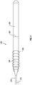
- FIG. 1 is an elevation side view and partial cross-section view of a guide wire 100 including features according to the present disclosure.
- Guide wire 100 may be adapted for insertion into a body lumen of a patient, for example a vein or artery.
- Guide wire 100 may include an elongate, relatively high strength proximal core portion 102 directly welded to a relatively flexible distal core portion 104 at weld joint 103.
- Weld joint 103 may be surrounded by a heat affected zone 105 as will be described below.
- Distal core portion 104 may include a tapered section 106, tapering to a smaller thickness in the distal direction.
- a helical coil 108 may be disposed about distal core section 104, which may be secured by its distal end to a distal end of shaping ribbon 110 (e.g., by solder) near rounded plug 112.
- a proximal end of shaping ribbon 110 may be secured (e.g., by solder) to distal core portion 104 at the same or a nearby location 114.
- a distal section 116 of coil 108 may be stretched in length to provide additional flexibility.
- Distal tip 118 of distal core portion 104 may be flattened into a rectangular cross-section, and may include a rounded tip 120 (e.g., solder) to prevent passage of distal tip 118 through any spaces between the coils of helical coil 108.
- FIG. 2 shows a simplified embodiment of another intravascular guide wire 200 including features of the present disclosure.
- Core portions 202 and 204 may be directly welded together at weld joint 203 during fabrication. Similar to guide wire 100, weld joint 203 includes a heat affected zone surrounding joint 203 as a result of the solid state deformation of the materials within this region.
- Portion 202 comprises as material stainless steel having a relatively higher modulus of elasticity.
- a distal end of portion 202 may be directly joined through a weld (e.g., a butt weld) formed through solid state deformation to distal portion 204, which comprises nitinol, having a relatively lower modulus of elasticity.
- a weld e.g., a butt weld
- Distal portion 204 may include a flattened, shapable distal tip 218 which can be permanently deformed (e.g., by finger pressure) to create a tip that can be steered through a patient's vasculature. As shown, distal tip 218 may be bent or deformed into a J, L or similar bend 219. A tip coil 208 may be disposed over distal core portion 204.
- guide wires 100, 200 are merely two of many possible configurations, and other guide wire configurations including multiple segments that may be directly joined together by a weld formed under solid state deformation conditions are encompassed by the present disclosure.
- Distal core section 104, 204 is, according to the present invention, made of a nickel-titanium alloy such as nitinol, a pseudoelastic alloy including about 30 atomic percent to about 52 atomic percent titanium, with the balance typically being nickel.
- a nickel-titanium alloy such as nitinol
- a pseudoelastic alloy including about 30 atomic percent to about 52 atomic percent titanium, with the balance typically being nickel.
- up to about 10 atomic percent or up to about 3 atomic percent of one or more other alloying elements may be included.
- Other alloying elements include, but are not limited to iron, cobalt, vanadium, platinum, palladium, copper, and combinations thereof. Where copper, vanadium, or combinations thereof are included, each may be included in amounts of up to about 10 atomic percent in one embodiment. In one embodiment, where iron, cobalt, platinum, palladium, or combinations thereof are included, each may be included in amounts of up to about 3 atomic percent.
- a guide wire having a distal portion made at least in substantial part of such material can be readily advanced through tortuous arterial passageways with minimal risk of kinking. Such characteristics are similarly beneficial where the distal nitinol portion of the guide wire may be prolapsed, either deliberately or inadvertently.
- proximal portion 102, 202 of guide wire 100, 200 may typically be significantly stronger (i.e., having higher tensile strength) than pseudoelastic distal portion 104, 204.
- proximal portion 102, 202 may be formed of stainless steel (e.g., SAE 304 stainless steel).
- Other high strength materials including, but not limited to cobalt-chromium alloys such as MP35N may also be employed.
- the method achieves direct joining of dissimilar metal materials to one another through a resistance, solid-state welding process in which the segments may be welded to one another.
- the welding process achieves the desired direct joint through solid state deformation of the ends of the two segments, without melting of either material.
- Such a method is particularly advantageous in the field of intravascular guide wires where the wire segments to be welded to one another are relatively small, such that known methods of solid state deformation weld bonding are unsuitable.
- welding processes capable of reliably joining dissimilar metals together without melting of either work piece are known.
- Such methods involve solid state bonding, rather than melting and fusion.
- a metallurgical bond is created while both materials remain in the solid state, typically through application of heat and pressure at the interface of the dissimilar metals.
- the earliest developed method known as forge welding, employs the blacksmith's technique of heating both work pieces near but below their respective melting points and forcing them together via successive hammer blows. Such a method is of course not suitable for welding fine wires together end-to-end, as may be required when joining multiple segments of a multi-segment intravascular guide wire.
- Another solid state joining method explosion welding, uses an engineered explosive charge to generate extremely high velocity and resulting high interfacial pressure between the pieces to be joined together. Such a method is employed in laminating sheet and plate materials, although it is not suitable for joining together fine wires.
- the present method overcomes the difficulties previously encountered when attempting to directly weld two dissimilar wire segments, for example end-to-end as in a multi-segment guide wire.
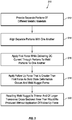
- multiple, initially separate portions of the guide wire, each comprising a different material are provided at S12.
- FIGS. 1 and 2 show two segments, it will be understood that the methods herein described may similarly be employed to join more than two segments together, without the need to position any transition piece between the incompatible, dissimilar metal segments for compatibility purposes. For example, were three segments desired, two segments may be joined, followed by joining the resulting structure with a third segment.
- the separate portions or segments are aligned (e.g., axially, end-to-end) with one another.
- a first force e.g., axial
- electrical e.g., DC, AC, or both
- a follow up force e.g., axial
- the weld nugget forms between the guide wire portions or segments.
- the resulting weld nugget is thinner and of a larger transverse cross-sectional area than would be produced without application of the follow up force.
- the method has been found to effectively and reliably directly join two dissimilar, incompatible elongate wire segments or portions to one another, while consistently achieving desired strength characteristics.
- the ends to be joined together may be prepared by flattening and smoothing the ends.
- Such end preparation may be achieved by grinding the mating ends just prior to alignment and the beginning of the welding process (i.e., when the first force is applied and electrical current is delivered through the segments). This may be so, even where the ends may have been smoothed and flattened previously, as removal of any oxide layers at this stage is desirable.
- the ends may be ground with a rotating disc covered with wet or dry sandpaper.
- An aqueous grinder coolant may serve to remove debris during the grinding step.
- Such a flattening and smoothing procedure acts to remove oxide from the wire ends, which oxide may otherwise interfere with the ability to achieve sufficient and consistent weld strength.
- the nitinol forms a titanium oxide layer
- the stainless steel includes a chromium oxide layer. It is beneficial to remove these oxide layers from the corresponding ends that are to be welded together. Removal of any oxide layers (e.g., preferably performed immediately prior to axial alignment and welding) minimizes contact resistance and reduces variability in contact resistance due to the presence of the oxide layers. This helps reduce variability in weld temperature from one weld to another, which helps in ensuring that no melting of either metal of the dissimilar wire segments occurs.
- preparation of the corresponding ends is performed “immediately prior to” or “just prior to” axial alignment and welding, it will be understood that some passage of time between preparation of the corresponding ends of the segments or portions to be joined together and axial alignment and butt welding of the segments or portions is acceptable so long as such time period is sufficiently short so as to prevent reformation of an oxide film over the prepared ends which could affect the contact resistance between said ends.
- preparation of the ends is performed within about 1 day of welding, within about 10 hours of welding, within about 1 hour of welding, within about 30 minutes of welding, within about 15 minutes of welding, within about 5 minutes of welding, within about 2 minutes of welding, or within about 1 minute of welding.
- the ends may be tightly pressed together (e.g., about 100,000 psi to about 200,000 psi) through application of the first force prior to application of any electrical (e.g., DC, AC, or both) current so as to prevent any air from being present therebetween that might result in reformation of the oxide layers.
- any electrical e.g., DC, AC, or both
- resistance heating and the application of the forces associated with the welding process may be undertaken in an inert environment, which may further aid in preventing formation of any undesirable oxide layers that would interfere with contact resistance and maintaining weld temperature within the desired window.
- the baseline first force may be applied axially, and applied at any desired level, which may depend at least in part on the dimensions and material characteristics of the wire segments to be joined together.
- the force applied may be from about 4.45 N (1 lb) to about 444.8 N (100 lbs), from 22.24 N to 222.41 N (5 lbs to 50 lbs), from about 44.48 N to about 133.45 N (10 lbs to 30 lbs), or from about 66.72 N to 111.20 N (15 lbs to 25 lbs).
- levels of force may result in pressures from about 689.47 MPa to about 1398.95 MPa (100,000 to 200,000 psi).
- the resulting pressure at the interface is about 1034.21 MPa (150,000 psi).
- the baseline force and the cross-sectional thickness of the wire segments may result in a pressure at the interface of the segments from about 241.31 MPa (13.5,000 psi) to about 2757.90 MPa (400,000 psi), from about 517.11 MPa (75,000 psi), to about 1723.69 MPa (250,000 psi), or from about 689.47 MPa (100,000 psi) to about 1378.95 MPa (200,000 psi).
- Wire segments having relatively larger cross-sectional area may be processed at relatively higher force levels to provide similar pressures.
- the wire segments so joined may have about the same diameter (e.g., within about 25%, within about 10%, within about 5%, or within about 1% of one another). In one embodiment, the wire segment diameters may be approximately equal (e.g., both about 0.33 mm [0.013 inch]).
- the baseline force may be applied while electrical (e.g., DC, AC, or both) current is applied to the segments.
- the value of the baseline force may be substantially constant over the period over which it is applied.
- electrical e.g., DC, AC, or both
- the regions adjacent the corresponding ends which are pressed together will begin to soften as the temperature increases. At some point, these regions will begin to collapse towards one another (i.e., solid state deformation) as setdown or axial displacement occurs, as a result of solid-state deformation.
- Electrical weld energy input may last from about 1 ms to about 100 ms, from about 5 ms to about 50 ms, or from about 10 ms to about 30 ms.
- the value of the applied current may depend on duration of the input, as well as the dimensions and material characteristics of the segments being joined together. In one embodiment, the applied current may be from about 0.01 kA to about 0.1 kA, from about 0.05 kA to about 0.08 kA, or from about 0.06 kA to about 0.07 kA. Of course, larger or smaller values than these ranges may be appropriate where the dimensions and/or material characteristics of the segments so dictate.
- Applied current may be DC current, AC current, or both.
- an embodiment may employ a high frequency inverter power source which may provide a DC pulse that may include high frequency AC overlaid on it.
- Such a power source may differ from standard AC in that the high frequency potential may not completely reverse polarity.
- the follow up force (e.g., axial) is applied after solid-state deformation (setdown) begins, but before, according to the present invention, such deformation has completed.
- the follow up force is applied according to the present invention as the electrical (e.g., DC, AC, or both) current delivery has stopped. In one embodiment, there is a gap between when electrical weld energy input stops and the start of application of the follow up force.
- application of the follow up force may begin from about 0.5 ms to about 10 ms after the end of electrical (e.g., DC, AC, or both) current delivery, from about 2 ms to about 8 ms after the end of electrical (e.g., DC, AC, or both) current delivery, or from about 3 ms to about 5 ms after the end of electrical (e.g., DC, AC, or both) current delivery.
- electrical e.g., DC, AC, or both
- the value of the applied follow up force may depend on the material characteristics and dimensions (e.g., diameter) of the segments being directly joined together.
- the follow up force may be from about 8.89 N to about 889.64 N (2 lbs to 200 lbs), from about 44.48 N to about 444.82 N (10 lbs to 100 lbs), from about 88.96 N to about 266.89 N (20 lbs to 60 lbs), or from about 133.47 N to about 177,93 N (30 lbs to 40 lbs).
- the follow up force and the cross-sectional thickness of the wire segments may result in a pressure at the interface of the segments from about 344.74 N to 5171.07 N (50,000 psi to 750,000 psi), from about 861.84 N to about 3102.64 N (125,000 to 450,000 psi), or from about 1206.58 N to about 2413.17 N (175,000 to 350,000 psi).
- a follow up force of 155.69 N (35 lbs) and a wire diameter of 0.33 mm (0.013 inch) results in a pressure of about 1827.11 MPa (265,000 psi).
- the follow up force and/or the pressure provided by the follow up force is from about 10% greater to about 200% greater than the baseline force (or baseline pressure), from about 25% greater to about 150% greater than the baseline force (or baseline pressure), or from about 50% greater to about 100% greater than the baseline force (or baseline pressure).
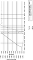
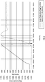
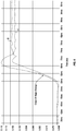
- FIGS. 4 and 5 plot electrical weld energy input and axial deformation profiles for directly butt welding a stainless steel proximal guide wire portion to a nitinol distal guide wire portion. Each portion had a diameter of about 0.33 mm (0.013 inch).
- the profiles shown in FIG. 4 are without application of a follow up axial force, while the profiles shown in FIG. 5 are with application of a follow up axial force.
- FIG. 5 the total axial displacement or setdown was 1.02 mm (0.0402 inch).
- the greater axial displacement value of FIG. 5 corresponds to a weld nugget of thinner cross-sectional thickness and greater transverse cross-sectional diameter than that of FIG. 4 .
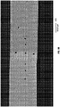
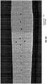
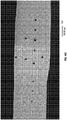
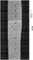
- Photographs of the two weld nuggets so formed are shown in FIGS. 8A and 8B .
- FIG. 6 shows the axial displacement profiles of FIGS. 4 and 5 on the same plot.
- the plotted profiles A and B begin substantially parallel to one another, with the divergence beginning at the point where the follow up axial force is applied in example B and not example A.
- a larger diameter weld nugget (associated with FIG. 5 ), including increased cross-sectional area at the interface between the dissimilar, incompatible materials serves to better accept such a transitory tensile load without pulling the weld apart or resulting in hidden damage within the weld nugget that might later lead to failure of the guide wire at the weld.
- application of the follow up force serves to squeeze and thereby extract heat from the weld nugget while substantially enlarging its cross-sectional area. Extraction of heat serves to decrease the temperature of the weld nugget, particularly its interface, thereby raising its strength and further improving its resistance to rebounding forces.
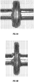
- FIG. 7A depicts an exemplary proximal and distal portion 302 and 304, respectively of a multi-segment guide wire 300 in the vicinity of the formed weld nugget.
- FIG. 7A corresponds to FIG. 4 , which does not include application of any follow up force.
- FIG. 7B depicts proximal and distal portions 302' and 304', respectively of a multi-segment guide wire 300' formed with application of a follow up axial force (corresponding to FIG. 5 ). These depictions correspond to the actual photographs shown in FIGS. 8A and 8B .
- the weld nugget 322 and 322' is seen disposed surrounding the interface where the respective proximal and distal portions are joined together.
- weld nugget 322' formed under conditions in which a larger follow up axial force is applied, exhibits a diameter D' that is at least about 5% greater, at least about 10% greater, or about 15% greater to about 25% greater than diameter D that would be produced without application of the follow up axial force.
- the diameter D' is about 20% larger in weld nugget 322' than diameter D of weld nugget 322
- the cross-sectional area of weld nugget 322' will be about 45% greater than the cross-sectional area of weld nugget 322. This significantly increased cross-sectional area (i.e., increased bonding area) better resists undesirable tensile loading due to mechanical rebounding.
- weld nugget 322' may have an average thickness T' that is from about 10% smaller to about 50% smaller, about 15% smaller to about 35% smaller, or about 20% smaller to about 30% smaller than thickness T that would be produced without application of the follow up axial force.
- the actual weld nuggets shown in FIGS. 8A and 8B exhibited an average thickness of 0.22 mm without application of a follow up force, and an average thickness of 0.15 mm with application of a follow up force.
- the resulting diameter shown in FIG. 8B was 20% larger than that shown in FIG. 8A , providing an increase in cross-sectional bonded surface area of 45%.
- FIGS. 4-8B While the embodiments described in FIGS. 4-8B are shown as being carried out under conditions in which the corresponding ends of the segments or portions are shaped and oriented to provide a butt joint as a result of the weld, it will be understood that other welded joint configurations, including but not limited to butt joints, overlap joints, joints including corresponding oblique angled ends, and combinations thereof may also be employed. Various alternative joint configurations that may be employed are shown in U.S. Patent No. 7,998,090 , herein incorporated by reference in its entirety.
- the weld nugget disposed therebetween can be removed by grinding.
- the majority of the excess weld nugget material extending laterally beyond the diameter of the adjacent proximal and distal segments may be ground away in a centerless grinding operation. Any remaining excess metal may be removed while grinding the entire distal core wire profile.
- multi-segment guide wires formed as described herein with application of an increased follow up force exhibit characteristics allowing them to be identified as having been produced according to such methods herein described.
- the resulting multi-segment guide wire includes a heat affected zone corresponding to the location of the weld nugget.
- a multi-segment guide wire may have a heat affected zone that has a thickness of less than about 0.20 mm, less than about 0.18 mm, or from about 0.15 mm to about 0.18 mm in thickness.
- Such reduced thickness heat affected zones provide improved kink resistance.
- the heat affected zone may also exhibit unique hardness characteristics as a result of the heat affected zone having undergone greater levels of solid state deformation arising from the follow up force. Specifically, the heat affected zone is expected to be narrower and exhibit a lesser degree of softening as compared with welds created without a follow up force.
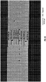
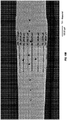
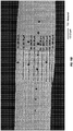
- Comparative measurements of the heat affected zone were carried out on multi-segment guide wires according to the present disclosure as compared to Terumo guide wires. Measurement of microhardness impressions within the stainless steel portion, the nickel-titanium portion, and the heat affected weld zone therebetween were taken using Vickers hardness testing. Each Vickers hardness measurement was made using 100 grams of force (HV100). Three measurements within each region were obtained. The results are shown in Tables 1A and 1B. AV1, AV2, and AV3 refer to multi-segment guide wires according to the present disclosure. T1, T2, and T3 refer to hardness tested Terumo guide wires.
- FIGS. 9A - 9E show images of the multi-segment guide wires AV1-AV3 that were measured.
- FIGS. 10A - 10F show images of the Terumo guide wires T1-T3.
- Comparative strength testing was performed on multi-segment guide wires formed according to methods described above in conjunction with FIGS. 4-5 .
- Multi-segment guide wires formed with and without application of a follow up axial force were subjected to destructive rotary bend testing (essentially a low-cycle fatigue test).
- Tensile testing may not always correlate to actual performance in bending conditions (which exist during use of the guide wires). For example, while a welding process may produce components that exhibit acceptable, even high tensile test values, the inventors have found that some such welded components perform poorly when subjected to bending.
- Rotary bend testing better approximates use conditions, and provides a better measurement of weld strength during use.
- the weld of each guide wire was simultaneously bent to a 90° and rotated one complete revolution (360°) in order to challenge all locations around the weld joint perimeter.
- the test design ensures that the weld interface will reside near the onset of the 90° bend, and thus participate in the curvature.
- the applied force incrementally increases during testing, the radius of curvature within the turn becomes tighter, thereby increasing the bend severity and further challenging the weld interface.
- Each rotary bend test result was recorded in psi, representing the actual air pressure being applied, at the moment of failure, to a piston used to apply the force.
- Each of groups A and B were formed in a manner similar to one another, other than application of the follow up axial force in group B. Manufacturing conditions were as described above in conjunction with FIGS. 4-5 .
- Group A had a significantly lower mean strength value, and the minimum strength value was only 0.014 MPa (2.0 psi), which is below a desired performance specification of 0.015 MPa (2.2 psi).
- Group B included a minimum strength value of 0.02 MPa (2.9 psi), well above the desired minimum of 0.015 MPa (2.2 psi).
- Cpk is a commonly employed index that quantifies how capable a process is of consistently meeting the desired specification. Higher values of Cpk correspond to better capability in consistently meeting the desired specification.
- Cpk is calculated by dividing the difference between the mean value and the specification by 3 standard deviations (i.e., (mean - 2.2)/(3x stdev)). As is readily apparent from Table 2, the Cpk value for group B is nearly double the Cpk value for group A.
- the comparative testing thus indicates that significantly greater consistency with respect to desired strength characteristics is achieved when forming the guide wires with application of a follow up axial force. This is particularly important where the guide wire exhibiting sub specification strength characteristics may not be readily recognizable through non-destructive quality control mechanisms.
- the inventive method of manufacture thus increases consistency within the manufactured guide wires, while decreasing any incidence of passing sub specification parts.
Landscapes
- Engineering & Computer Science (AREA)
- Mechanical Engineering (AREA)
- Health & Medical Sciences (AREA)
- Life Sciences & Earth Sciences (AREA)
- Biophysics (AREA)
- Pulmonology (AREA)
- Anesthesiology (AREA)
- Biomedical Technology (AREA)
- Heart & Thoracic Surgery (AREA)
- Hematology (AREA)
- Animal Behavior & Ethology (AREA)
- General Health & Medical Sciences (AREA)
- Public Health (AREA)
- Veterinary Medicine (AREA)
- Media Introduction/Drainage Providing Device (AREA)
- Pressure Welding/Diffusion-Bonding (AREA)
- Surgical Instruments (AREA)
- Arc Welding In General (AREA)
Priority Applications (1)
| Application Number | Priority Date | Filing Date | Title |
|---|---|---|---|
| EP17159014.4A EP3192608B1 (en) | 2013-01-17 | 2014-01-16 | Multi segment intravascular guide wire with a welding ; method of counteracting rebounding effects during solid state resistance welding of dissimilar materials |
Applications Claiming Priority (2)
| Application Number | Priority Date | Filing Date | Title |
|---|---|---|---|
| US13/744,276 US9636485B2 (en) | 2013-01-17 | 2013-01-17 | Methods for counteracting rebounding effects during solid state resistance welding of dissimilar materials |
| PCT/US2014/011777 WO2014113527A1 (en) | 2013-01-17 | 2014-01-16 | Methods for counteracting rebounding effects during solid state resistance welding of dissimilar materials |
Related Child Applications (1)
| Application Number | Title | Priority Date | Filing Date |
|---|---|---|---|
| EP17159014.4A Division EP3192608B1 (en) | 2013-01-17 | 2014-01-16 | Multi segment intravascular guide wire with a welding ; method of counteracting rebounding effects during solid state resistance welding of dissimilar materials |
Publications (2)
| Publication Number | Publication Date |
|---|---|
| EP2945768A1 EP2945768A1 (en) | 2015-11-25 |
| EP2945768B1 true EP2945768B1 (en) | 2017-03-08 |
Family
ID=50033826
Family Applications (2)
| Application Number | Title | Priority Date | Filing Date |
|---|---|---|---|
| EP14702708.0A Not-in-force EP2945768B1 (en) | 2013-01-17 | 2014-01-16 | Method of counteracting rebounding effects during solid state resistance welding of dissimilar materials |
| EP17159014.4A Active EP3192608B1 (en) | 2013-01-17 | 2014-01-16 | Multi segment intravascular guide wire with a welding ; method of counteracting rebounding effects during solid state resistance welding of dissimilar materials |
Family Applications After (1)
| Application Number | Title | Priority Date | Filing Date |
|---|---|---|---|
| EP17159014.4A Active EP3192608B1 (en) | 2013-01-17 | 2014-01-16 | Multi segment intravascular guide wire with a welding ; method of counteracting rebounding effects during solid state resistance welding of dissimilar materials |
Country Status (5)
| Country | Link |
|---|---|
| US (6) | US9636485B2 (enExample) |
| EP (2) | EP2945768B1 (enExample) |
| JP (1) | JP6351628B2 (enExample) |
| CN (1) | CN105142845B (enExample) |
| WO (1) | WO2014113527A1 (enExample) |
Families Citing this family (12)
| Publication number | Priority date | Publication date | Assignee | Title |
|---|---|---|---|---|
| US9061088B2 (en) | 2012-02-02 | 2015-06-23 | Abbott Cardiovascular Systems, Inc. | Guide wire core wire made from a substantially titanium-free alloy for enhanced guide wire steering response |
| US9636485B2 (en) | 2013-01-17 | 2017-05-02 | Abbott Cardiovascular Systems, Inc. | Methods for counteracting rebounding effects during solid state resistance welding of dissimilar materials |
| US20150045695A1 (en) * | 2013-08-06 | 2015-02-12 | Abbott Cardiovascular Systems, Inc. | Guide wire with core made from low-modulus cobalt-chromium alloy |
| US10071229B2 (en) | 2015-04-14 | 2018-09-11 | Abbott Cardiovascular Systems, Inc. | Mechanisms for improving the stiffness transition across a dissimilar metal weld joint |
| JP2019516011A (ja) | 2016-04-20 | 2019-06-13 | アーコニック インコーポレイテッドArconic Inc. | アルミニウム、コバルト、鉄、及びニッケルのfcc材料、並びにそれを用いた製品 |
| WO2017184778A1 (en) | 2016-04-20 | 2017-10-26 | Arconic Inc. | Fcc materials of aluminum, cobalt and nickel, and products made therefrom |
| US11278701B2 (en) | 2016-10-13 | 2022-03-22 | Lake Region Manufacturing, Inc. | Apparatus including multiple joined hypotubes and method of making same |
| JP6596470B2 (ja) * | 2017-07-20 | 2019-10-23 | トクセン工業株式会社 | 医療処置具用ワイヤ及びガイドワイヤ |
| JP7372907B2 (ja) * | 2017-08-31 | 2023-11-01 | コーニンクレッカ フィリップス エヌ ヴェ | 一体化された近位ロッキングフィーチャを持つ感知ガイドワイヤ |
| JP7557528B2 (ja) | 2020-03-30 | 2024-09-27 | テルモ株式会社 | ガイドワイヤ |
| CN115068789B (zh) * | 2021-10-22 | 2024-03-01 | 美度可医疗科技(上海)有限公司 | 一种平滑的异金属核芯导丝 |
| US20240374871A1 (en) * | 2023-05-11 | 2024-11-14 | Abbott Cardiovascular Systems Inc. | Twisted guidewire |
Family Cites Families (94)
| Publication number | Priority date | Publication date | Assignee | Title |
|---|---|---|---|---|
| US1793218A (en) * | 1928-07-16 | 1931-02-17 | Jones & Laughlin Steel Corp | Apparatus for making welded pipe |
| US2323660A (en) * | 1942-03-07 | 1943-07-06 | Mallory & Co Inc P R | Flash-arc welding |
| US3259969A (en) * | 1963-01-22 | 1966-07-12 | Central Cable Corp | Method of making butt welded joints |
| US3660176A (en) * | 1970-02-10 | 1972-05-02 | Armco Steel Corp | Precipitation-hardenable stainless steel method and product |
| US3961153A (en) * | 1974-05-24 | 1976-06-01 | Trw Inc. | Machine for fabricating a wire network |
| DE2538295A1 (de) | 1975-08-28 | 1977-03-10 | Bosch Gmbh Robert | Verfahren zum herstellen einer elektrisch leitenden und mechanisch festen verbindung von aluminiumleitern an kupferkommutatoren |
| US4358658A (en) | 1980-12-05 | 1982-11-09 | The United States Of America As Represented By The United States Department Of Energy | Laser weld jig |
| CH660882A5 (de) | 1982-02-05 | 1987-05-29 | Bbc Brown Boveri & Cie | Werkstoff mit zweiweg-gedaechtniseffekt und verfahren zu dessen herstellung. |
| EP0097306B1 (en) * | 1982-06-18 | 1990-05-23 | Scm Corporation | Method of making dispersion strengthened metal bodies and product |
| US4934380A (en) * | 1987-11-27 | 1990-06-19 | Boston Scientific Corporation | Medical guidewire |
| US4922924A (en) | 1989-04-27 | 1990-05-08 | C. R. Bard, Inc. | Catheter guidewire with varying radiopacity |
| JPH03243296A (ja) | 1990-02-22 | 1991-10-30 | Kobe Steel Ltd | ステンレス鋼用フラックス入りワイヤ |
| US5135503A (en) | 1990-05-16 | 1992-08-04 | Advanced Cardiovascular Systems, Inc. | Shaping ribbon for guiding members |
| DE69129098T2 (de) | 1990-12-18 | 1998-09-17 | Advanced Cardiovascular System | Verfahren zur Herstellung eines super-elastischen Führungsteils |
| US5341818A (en) * | 1992-12-22 | 1994-08-30 | Advanced Cardiovascular Systems, Inc. | Guidewire with superelastic distal portion |
| ATE140647T1 (de) * | 1991-04-09 | 1996-08-15 | Furukawa Electric Co Ltd | Verbundene teile von ni-ti-legierugen mit verschiedenen metallen und verbindungsverfahren dafür |
| US5354623A (en) | 1991-05-21 | 1994-10-11 | Cook Incorporated | Joint, a laminate, and a method of preparing a nickel-titanium alloy member surface for bonding to another layer of metal |
| US5415178A (en) | 1991-08-26 | 1995-05-16 | Target Therapeutics | Extendable guidewire assembly |
| US5630840A (en) | 1993-01-19 | 1997-05-20 | Schneider (Usa) Inc | Clad composite stent |
| US5769796A (en) * | 1993-05-11 | 1998-06-23 | Target Therapeutics, Inc. | Super-elastic composite guidewire |
| US5772609A (en) * | 1993-05-11 | 1998-06-30 | Target Therapeutics, Inc. | Guidewire with variable flexibility due to polymeric coatings |
| JP3343394B2 (ja) * | 1993-05-24 | 2002-11-11 | 中央精機株式会社 | アルミ合金のアプセットバット溶接方法 |
| US5720300A (en) | 1993-11-10 | 1998-02-24 | C. R. Bard, Inc. | High performance wires for use in medical devices and alloys therefor |
| US5488959A (en) * | 1993-12-27 | 1996-02-06 | Cordis Corporation | Medical guidewire and welding process |
| US6736843B1 (en) | 1994-07-25 | 2004-05-18 | Advanced Cardiovascular Systems, Inc. | Cylindrically-shaped balloon-expandable stent |
| DE69517501T2 (de) * | 1995-03-02 | 2001-03-08 | Schneider (Europe) Gmbh, Buelach | Verfahren zur Herstellung eines Führungsdrahtes |
| US5916178A (en) | 1995-03-30 | 1999-06-29 | Medtronic, Inc. | Steerable high support guidewire with thin wall nitinol tube |
| US5724989A (en) | 1995-06-20 | 1998-03-10 | The Microspring Company, Inc. | Radiopaque medical devices |
| US6019736A (en) * | 1995-11-06 | 2000-02-01 | Francisco J. Avellanet | Guidewire for catheter |
| US6000601A (en) | 1996-10-22 | 1999-12-14 | Boston Scientific Corporation | Welding method |
| US6001068A (en) | 1996-10-22 | 1999-12-14 | Terumo Kabushiki Kaisha | Guide wire having tubular connector with helical slits |
| EP0887084B1 (en) | 1997-06-24 | 2004-08-11 | Asahi Intecc Co., Ltd. | A connecting structure for a guide wire used for medical treatment |
| US5980471A (en) | 1997-10-10 | 1999-11-09 | Advanced Cardiovascular System, Inc. | Guidewire with tubular connector |
| US5951886A (en) | 1997-12-23 | 1999-09-14 | Ptr Precision Technologies | Apparatus for electron beam welding at atmospheric pressure |
| US20060047223A1 (en) * | 2004-08-31 | 2006-03-02 | Ryan Grandfield | Apparatus and method for joining stainless steel guide wire portion to nitinol portion, without a hypotube |
| US6306105B1 (en) | 1998-05-14 | 2001-10-23 | Scimed Life Systems, Inc. | High performance coil wire |
| US6387060B1 (en) | 1998-06-17 | 2002-05-14 | Advanced Cardiovascular Systems, Inc. | Composite radiopaque intracorporeal product |
| US6267776B1 (en) | 1999-05-03 | 2001-07-31 | O'connell Paul T. | Vena cava filter and method for treating pulmonary embolism |
| US6645159B1 (en) | 1999-11-30 | 2003-11-11 | Advanced Cardiovascular Systems, Inc. | Wire joint and method |
| JP2004517732A (ja) | 2000-06-21 | 2004-06-17 | シーメンス アクチエンゲゼルシヤフト | 形状記憶材と鋼材又は銅材との間の結合方法 |
| US6669652B2 (en) | 2000-12-21 | 2003-12-30 | Advanced Cardiovascular Systems, Inc. | Guidewire with tapered distal coil |
| JP2003049249A (ja) | 2001-08-09 | 2003-02-21 | Hitachi Metals Ltd | ガイドワイヤ用材料及びその製造方法 |
| JP4199446B2 (ja) | 2001-09-12 | 2008-12-17 | 株式会社日立製作所 | 摩擦攪拌接合装置 |
| JP4494782B2 (ja) | 2001-10-05 | 2010-06-30 | ボストン サイエンティフィック リミテッド | 複合ガイドワイヤ |
| US6918882B2 (en) | 2001-10-05 | 2005-07-19 | Scimed Life Systems, Inc. | Guidewire with stiffness blending connection |
| US6799067B2 (en) * | 2001-12-26 | 2004-09-28 | Advanced Cardiovascular Systems, Inc. | MRI compatible guide wire |
| US6702762B2 (en) | 2001-12-27 | 2004-03-09 | Advanced Cardiovascular Systems, Inc. | Apparatus and method for joining two guide wire core materials without a hypotube |
| JP4136370B2 (ja) | 2001-12-28 | 2008-08-20 | トクセン工業株式会社 | 医療用ガイドワイヤ用芯材の製造方法および医療用ガイドワイヤ |
| US7126078B2 (en) * | 2002-02-28 | 2006-10-24 | Emcore Corporation | Sub-micron adjustable mount for supporting a component and method |
| JP4809575B2 (ja) | 2002-03-29 | 2011-11-09 | 太平洋セメント株式会社 | 土木構造物用セメント組成物及びこれを用いたコンクリート製品 |
| US6968237B2 (en) | 2002-05-22 | 2005-11-22 | Pacesetter, Inc. | Implantable coronary sinus lead and lead system |
| JP4203358B2 (ja) * | 2002-08-08 | 2008-12-24 | テルモ株式会社 | ガイドワイヤ |
| JP2004065796A (ja) | 2002-08-08 | 2004-03-04 | Terumo Corp | ガイドワイヤ |
| JP4375951B2 (ja) | 2002-08-08 | 2009-12-02 | テルモ株式会社 | ガイドワイヤ |
| JP5089517B2 (ja) * | 2002-08-08 | 2012-12-05 | テルモ株式会社 | ガイドワイヤ |
| US7722551B2 (en) | 2002-08-09 | 2010-05-25 | Terumo Kabushiki Kaisha | Guide wire |
| JP4138582B2 (ja) * | 2002-08-23 | 2008-08-27 | テルモ株式会社 | ガイドワイヤ |
| DE60331328D1 (de) | 2002-10-04 | 2010-04-01 | Advanced Cardiovascular System | Strahlungsundurchlässige nitinollegierungen für medizinische geräte |
| US6866642B2 (en) | 2002-11-25 | 2005-03-15 | Advanced Cardiovascular Systems, Inc. | Enhanced method for joining two core wires |
| US20040116831A1 (en) | 2002-12-13 | 2004-06-17 | Scimed Life Systems, Inc. | Distal protection guidewire with nitinol core |
| US7182735B2 (en) | 2003-02-26 | 2007-02-27 | Scimed Life Systems, Inc. | Elongated intracorporal medical device |
| JP4416421B2 (ja) | 2003-03-18 | 2010-02-17 | テルモ株式会社 | ガイドワイヤおよびその製造方法 |
| US6875949B2 (en) * | 2003-03-19 | 2005-04-05 | Edison Welding Institute | Method of welding titanium and titanium based alloys to ferrous metals |
| JP4677205B2 (ja) | 2003-07-17 | 2011-04-27 | テルモ株式会社 | ガイドワイヤ |
| US8048369B2 (en) | 2003-09-05 | 2011-11-01 | Ati Properties, Inc. | Cobalt-nickel-chromium-molybdenum alloys with reduced level of titanium nitride inclusions |
| US7785273B2 (en) | 2003-09-22 | 2010-08-31 | Boston Scientific Scimed, Inc. | Guidewire with reinforcing member |
| CN100558423C (zh) | 2003-12-18 | 2009-11-11 | 泰尔茂株式会社 | 导向线 |
| JP4376048B2 (ja) * | 2003-12-18 | 2009-12-02 | テルモ株式会社 | ガイドワイヤ |
| US7824345B2 (en) | 2003-12-22 | 2010-11-02 | Boston Scientific Scimed, Inc. | Medical device with push force limiter |
| US7164094B2 (en) * | 2004-01-12 | 2007-01-16 | General Electric Company | Apparatus and method for electrofriction welding |
| US7993387B2 (en) * | 2004-05-14 | 2011-08-09 | Boston Scientific Scimed, Inc. | Stent with reduced weld profiles and a closed-end wire configuration |
| WO2006002199A2 (en) | 2004-06-22 | 2006-01-05 | Lake Region Manufacturing, Inc. | Variable stiffness guidewire |
| US7998090B2 (en) | 2004-08-31 | 2011-08-16 | Abbott Cardiovascular Systems Inc. | Guide wire with core having welded wire segments |
| JP4734015B2 (ja) | 2005-04-15 | 2011-07-27 | テルモ株式会社 | ガイドワイヤの製造方法 |
| US20060259063A1 (en) | 2005-04-25 | 2006-11-16 | Bates Brian L | Wire guides having distal anchoring devices |
| US7627382B2 (en) | 2005-05-25 | 2009-12-01 | Lake Region Manufacturing, Inc. | Medical devices with aromatic polyimide coating |
| US8267872B2 (en) | 2005-07-07 | 2012-09-18 | St. Jude Medical, Cardiology Division, Inc. | Steerable guide wire with torsionally stable tip |
| US20070185415A1 (en) | 2005-07-07 | 2007-08-09 | Ressemann Thomas V | Steerable guide wire with torsionally stable tip |
| US7683288B2 (en) * | 2005-08-12 | 2010-03-23 | Thermatool Corp. | System and method of computing the operating parameters of a forge welding machine |
| US20070244413A1 (en) * | 2006-04-12 | 2007-10-18 | Medtronic Vascular, Inc. | Medical guidewire tip construction |
| US7731669B2 (en) * | 2006-05-12 | 2010-06-08 | Concert Medical, Llc | Guidewire formed with composite construction and method for making the same |
| JP2010501360A (ja) * | 2006-08-30 | 2010-01-21 | フルオー・テクノロジーズ・コーポレイシヨン | 異種材料溶接のための構成および方法 |
| US7896820B2 (en) | 2006-12-26 | 2011-03-01 | Terumo Kabushiki Kaisha | Guide wire |
| JP4917900B2 (ja) | 2007-01-12 | 2012-04-18 | テルモ株式会社 | ガイドワイヤ用中間部材およびガイドワイヤ |
| JP4277117B2 (ja) * | 2007-03-29 | 2009-06-10 | 福井県 | ニッケル・チタン合金材料及び純チタン材料の異種金属接合体並びにその接合方法 |
| WO2008123402A1 (ja) | 2007-03-29 | 2008-10-16 | Fukui Prefectural Government | 異種金属接合体及びその接合方法 |
| US8105246B2 (en) * | 2007-08-03 | 2012-01-31 | Boston Scientific Scimed, Inc. | Elongate medical device having enhanced torque and methods thereof |
| WO2010033873A1 (en) | 2008-09-19 | 2010-03-25 | Fort Wayne Metals Research Products Corporation | Fatigue damage resistant wire and method of production thereof |
| US20120283700A1 (en) * | 2011-05-04 | 2012-11-08 | Abbott Cardiovascular Systems Inc. | Multi-metal guide wire coil |
| US20120305533A1 (en) | 2011-06-02 | 2012-12-06 | Taylor Winfield Technologies, Inc. | Forced freeze welding of advanced high strength steels |
| JP5876244B2 (ja) * | 2011-07-29 | 2016-03-02 | Jfeテクノワイヤ株式会社 | 溶接接合方法 |
| WO2013096669A2 (en) * | 2011-12-21 | 2013-06-27 | Alcoa Inc. | Apparatus and methods for joining dissimilar materials |
| US9061088B2 (en) | 2012-02-02 | 2015-06-23 | Abbott Cardiovascular Systems, Inc. | Guide wire core wire made from a substantially titanium-free alloy for enhanced guide wire steering response |
| US9636485B2 (en) | 2013-01-17 | 2017-05-02 | Abbott Cardiovascular Systems, Inc. | Methods for counteracting rebounding effects during solid state resistance welding of dissimilar materials |
-
2013
- 2013-01-17 US US13/744,276 patent/US9636485B2/en active Active
-
2014
- 2014-01-16 EP EP14702708.0A patent/EP2945768B1/en not_active Not-in-force
- 2014-01-16 WO PCT/US2014/011777 patent/WO2014113527A1/en not_active Ceased
- 2014-01-16 JP JP2015553815A patent/JP6351628B2/ja active Active
- 2014-01-16 CN CN201480010026.2A patent/CN105142845B/zh not_active Expired - Fee Related
- 2014-01-16 EP EP17159014.4A patent/EP3192608B1/en active Active
-
2017
- 2017-04-24 US US15/494,970 patent/US10717145B2/en active Active
-
2020
- 2020-06-10 US US16/897,784 patent/US11440127B2/en active Active
-
2022
- 2022-07-06 US US17/858,343 patent/US11931817B2/en active Active
-
2024
- 2024-02-07 US US18/435,259 patent/US12325083B2/en active Active
-
2025
- 2025-05-15 US US19/209,515 patent/US20250269458A1/en active Pending
Non-Patent Citations (1)
| Title |
|---|
| None * |
Also Published As
| Publication number | Publication date |
|---|---|
| US20220331896A1 (en) | 2022-10-20 |
| EP3192608A1 (en) | 2017-07-19 |
| CN105142845B (zh) | 2019-03-22 |
| US12325083B2 (en) | 2025-06-10 |
| US10717145B2 (en) | 2020-07-21 |
| CN105142845A (zh) | 2015-12-09 |
| US20200298332A1 (en) | 2020-09-24 |
| US9636485B2 (en) | 2017-05-02 |
| EP3192608B1 (en) | 2019-11-27 |
| US11440127B2 (en) | 2022-09-13 |
| WO2014113527A1 (en) | 2014-07-24 |
| US20240181556A1 (en) | 2024-06-06 |
| JP2016510261A (ja) | 2016-04-07 |
| JP6351628B2 (ja) | 2018-07-04 |
| US20140200555A1 (en) | 2014-07-17 |
| WO2014113527A4 (en) | 2014-08-28 |
| EP2945768A1 (en) | 2015-11-25 |
| US20170225260A1 (en) | 2017-08-10 |
| US11931817B2 (en) | 2024-03-19 |
| US20250269458A1 (en) | 2025-08-28 |
Similar Documents
| Publication | Publication Date | Title |
|---|---|---|
| US12325083B2 (en) | Methods for counteracting rebounding effects during solid state resistance welding of dissimilar materials | |
| US11129970B2 (en) | Mechanisms for improving the stiffness transition across a dissimilar metal weld joint | |
| EP2724745B1 (en) | Method of joining guide wire segments | |
| EP1578470B1 (en) | Guidewire tip construction | |
| CN100558423C (zh) | 导向线 | |
| US20150045695A1 (en) | Guide wire with core made from low-modulus cobalt-chromium alloy | |
| US20160279391A1 (en) | Solid state methods for joining dissimilar metal guidewire segments without the use of tertiary material | |
| US20080306453A1 (en) | Coupling wire guide and method for making same | |
| JP2004181089A (ja) | ガイドワイヤ |
Legal Events
| Date | Code | Title | Description |
|---|---|---|---|
| PUAI | Public reference made under article 153(3) epc to a published international application that has entered the european phase |
Free format text: ORIGINAL CODE: 0009012 |
|
| 17P | Request for examination filed |
Effective date: 20150812 |
|
| AK | Designated contracting states |
Kind code of ref document: A1 Designated state(s): AL AT BE BG CH CY CZ DE DK EE ES FI FR GB GR HR HU IE IS IT LI LT LU LV MC MK MT NL NO PL PT RO RS SE SI SK SM TR |
|
| AX | Request for extension of the european patent |
Extension state: BA ME |
|
| DAX | Request for extension of the european patent (deleted) | ||
| GRAP | Despatch of communication of intention to grant a patent |
Free format text: ORIGINAL CODE: EPIDOSNIGR1 |
|
| INTG | Intention to grant announced |
Effective date: 20160928 |
|
| GRAS | Grant fee paid |
Free format text: ORIGINAL CODE: EPIDOSNIGR3 |
|
| GRAA | (expected) grant |
Free format text: ORIGINAL CODE: 0009210 |
|
| AK | Designated contracting states |
Kind code of ref document: B1 Designated state(s): AL AT BE BG CH CY CZ DE DK EE ES FI FR GB GR HR HU IE IS IT LI LT LU LV MC MK MT NL NO PL PT RO RS SE SI SK SM TR |
|
| REG | Reference to a national code |
Ref country code: GB Ref legal event code: FG4D |
|
| REG | Reference to a national code |
Ref country code: AT Ref legal event code: REF Ref document number: 873093 Country of ref document: AT Kind code of ref document: T Effective date: 20170315 Ref country code: CH Ref legal event code: EP |
|
| REG | Reference to a national code |
Ref country code: IE Ref legal event code: FG4D |
|
| REG | Reference to a national code |
Ref country code: DE Ref legal event code: R096 Ref document number: 602014007383 Country of ref document: DE |
|
| REG | Reference to a national code |
Ref country code: NL Ref legal event code: FP |
|
| REG | Reference to a national code |
Ref country code: LT Ref legal event code: MG4D |
|
| PG25 | Lapsed in a contracting state [announced via postgrant information from national office to epo] |
Ref country code: LT Free format text: LAPSE BECAUSE OF FAILURE TO SUBMIT A TRANSLATION OF THE DESCRIPTION OR TO PAY THE FEE WITHIN THE PRESCRIBED TIME-LIMIT Effective date: 20170308 Ref country code: GR Free format text: LAPSE BECAUSE OF FAILURE TO SUBMIT A TRANSLATION OF THE DESCRIPTION OR TO PAY THE FEE WITHIN THE PRESCRIBED TIME-LIMIT Effective date: 20170609 Ref country code: NO Free format text: LAPSE BECAUSE OF FAILURE TO SUBMIT A TRANSLATION OF THE DESCRIPTION OR TO PAY THE FEE WITHIN THE PRESCRIBED TIME-LIMIT Effective date: 20170608 Ref country code: FI Free format text: LAPSE BECAUSE OF FAILURE TO SUBMIT A TRANSLATION OF THE DESCRIPTION OR TO PAY THE FEE WITHIN THE PRESCRIBED TIME-LIMIT Effective date: 20170308 Ref country code: HR Free format text: LAPSE BECAUSE OF FAILURE TO SUBMIT A TRANSLATION OF THE DESCRIPTION OR TO PAY THE FEE WITHIN THE PRESCRIBED TIME-LIMIT Effective date: 20170308 |
|
| REG | Reference to a national code |
Ref country code: AT Ref legal event code: MK05 Ref document number: 873093 Country of ref document: AT Kind code of ref document: T Effective date: 20170308 |
|
| PG25 | Lapsed in a contracting state [announced via postgrant information from national office to epo] |
Ref country code: BG Free format text: LAPSE BECAUSE OF FAILURE TO SUBMIT A TRANSLATION OF THE DESCRIPTION OR TO PAY THE FEE WITHIN THE PRESCRIBED TIME-LIMIT Effective date: 20170608 Ref country code: RS Free format text: LAPSE BECAUSE OF FAILURE TO SUBMIT A TRANSLATION OF THE DESCRIPTION OR TO PAY THE FEE WITHIN THE PRESCRIBED TIME-LIMIT Effective date: 20170308 Ref country code: ES Free format text: LAPSE BECAUSE OF FAILURE TO SUBMIT A TRANSLATION OF THE DESCRIPTION OR TO PAY THE FEE WITHIN THE PRESCRIBED TIME-LIMIT Effective date: 20170308 Ref country code: LV Free format text: LAPSE BECAUSE OF FAILURE TO SUBMIT A TRANSLATION OF THE DESCRIPTION OR TO PAY THE FEE WITHIN THE PRESCRIBED TIME-LIMIT Effective date: 20170308 Ref country code: SE Free format text: LAPSE BECAUSE OF FAILURE TO SUBMIT A TRANSLATION OF THE DESCRIPTION OR TO PAY THE FEE WITHIN THE PRESCRIBED TIME-LIMIT Effective date: 20170308 |
|
| PG25 | Lapsed in a contracting state [announced via postgrant information from national office to epo] |
Ref country code: EE Free format text: LAPSE BECAUSE OF FAILURE TO SUBMIT A TRANSLATION OF THE DESCRIPTION OR TO PAY THE FEE WITHIN THE PRESCRIBED TIME-LIMIT Effective date: 20170308 Ref country code: CZ Free format text: LAPSE BECAUSE OF FAILURE TO SUBMIT A TRANSLATION OF THE DESCRIPTION OR TO PAY THE FEE WITHIN THE PRESCRIBED TIME-LIMIT Effective date: 20170308 Ref country code: RO Free format text: LAPSE BECAUSE OF FAILURE TO SUBMIT A TRANSLATION OF THE DESCRIPTION OR TO PAY THE FEE WITHIN THE PRESCRIBED TIME-LIMIT Effective date: 20170308 Ref country code: SK Free format text: LAPSE BECAUSE OF FAILURE TO SUBMIT A TRANSLATION OF THE DESCRIPTION OR TO PAY THE FEE WITHIN THE PRESCRIBED TIME-LIMIT Effective date: 20170308 Ref country code: AT Free format text: LAPSE BECAUSE OF FAILURE TO SUBMIT A TRANSLATION OF THE DESCRIPTION OR TO PAY THE FEE WITHIN THE PRESCRIBED TIME-LIMIT Effective date: 20170308 |
|
| PG25 | Lapsed in a contracting state [announced via postgrant information from national office to epo] |
Ref country code: SM Free format text: LAPSE BECAUSE OF FAILURE TO SUBMIT A TRANSLATION OF THE DESCRIPTION OR TO PAY THE FEE WITHIN THE PRESCRIBED TIME-LIMIT Effective date: 20170308 Ref country code: IS Free format text: LAPSE BECAUSE OF FAILURE TO SUBMIT A TRANSLATION OF THE DESCRIPTION OR TO PAY THE FEE WITHIN THE PRESCRIBED TIME-LIMIT Effective date: 20170708 Ref country code: PT Free format text: LAPSE BECAUSE OF FAILURE TO SUBMIT A TRANSLATION OF THE DESCRIPTION OR TO PAY THE FEE WITHIN THE PRESCRIBED TIME-LIMIT Effective date: 20170710 Ref country code: PL Free format text: LAPSE BECAUSE OF FAILURE TO SUBMIT A TRANSLATION OF THE DESCRIPTION OR TO PAY THE FEE WITHIN THE PRESCRIBED TIME-LIMIT Effective date: 20170308 |
|
| REG | Reference to a national code |
Ref country code: DE Ref legal event code: R097 Ref document number: 602014007383 Country of ref document: DE |
|
| REG | Reference to a national code |
Ref country code: FR Ref legal event code: PLFP Year of fee payment: 5 |
|
| PLBE | No opposition filed within time limit |
Free format text: ORIGINAL CODE: 0009261 |
|
| STAA | Information on the status of an ep patent application or granted ep patent |
Free format text: STATUS: NO OPPOSITION FILED WITHIN TIME LIMIT |
|
| PG25 | Lapsed in a contracting state [announced via postgrant information from national office to epo] |
Ref country code: DK Free format text: LAPSE BECAUSE OF FAILURE TO SUBMIT A TRANSLATION OF THE DESCRIPTION OR TO PAY THE FEE WITHIN THE PRESCRIBED TIME-LIMIT Effective date: 20170308 |
|
| 26N | No opposition filed |
Effective date: 20171211 |
|
| PG25 | Lapsed in a contracting state [announced via postgrant information from national office to epo] |
Ref country code: IT Free format text: LAPSE BECAUSE OF FAILURE TO SUBMIT A TRANSLATION OF THE DESCRIPTION OR TO PAY THE FEE WITHIN THE PRESCRIBED TIME-LIMIT Effective date: 20170308 Ref country code: SI Free format text: LAPSE BECAUSE OF FAILURE TO SUBMIT A TRANSLATION OF THE DESCRIPTION OR TO PAY THE FEE WITHIN THE PRESCRIBED TIME-LIMIT Effective date: 20170308 |
|
| REG | Reference to a national code |
Ref country code: CH Ref legal event code: PL |
|
| PG25 | Lapsed in a contracting state [announced via postgrant information from national office to epo] |
Ref country code: LU Free format text: LAPSE BECAUSE OF NON-PAYMENT OF DUE FEES Effective date: 20180116 |
|
| REG | Reference to a national code |
Ref country code: BE Ref legal event code: MM Effective date: 20180131 |
|
| PG25 | Lapsed in a contracting state [announced via postgrant information from national office to epo] |
Ref country code: LI Free format text: LAPSE BECAUSE OF NON-PAYMENT OF DUE FEES Effective date: 20180131 Ref country code: CH Free format text: LAPSE BECAUSE OF NON-PAYMENT OF DUE FEES Effective date: 20180131 Ref country code: BE Free format text: LAPSE BECAUSE OF NON-PAYMENT OF DUE FEES Effective date: 20180131 |
|
| PGFP | Annual fee paid to national office [announced via postgrant information from national office to epo] |
Ref country code: FR Payment date: 20181221 Year of fee payment: 6 |
|
| PG25 | Lapsed in a contracting state [announced via postgrant information from national office to epo] |
Ref country code: MC Free format text: LAPSE BECAUSE OF FAILURE TO SUBMIT A TRANSLATION OF THE DESCRIPTION OR TO PAY THE FEE WITHIN THE PRESCRIBED TIME-LIMIT Effective date: 20170308 |
|
| PG25 | Lapsed in a contracting state [announced via postgrant information from national office to epo] |
Ref country code: MT Free format text: LAPSE BECAUSE OF NON-PAYMENT OF DUE FEES Effective date: 20180116 |
|
| PGFP | Annual fee paid to national office [announced via postgrant information from national office to epo] |
Ref country code: IE Payment date: 20191230 Year of fee payment: 7 |
|
| PG25 | Lapsed in a contracting state [announced via postgrant information from national office to epo] |
Ref country code: TR Free format text: LAPSE BECAUSE OF FAILURE TO SUBMIT A TRANSLATION OF THE DESCRIPTION OR TO PAY THE FEE WITHIN THE PRESCRIBED TIME-LIMIT Effective date: 20170308 |
|
| PGFP | Annual fee paid to national office [announced via postgrant information from national office to epo] |
Ref country code: NL Payment date: 20200102 Year of fee payment: 7 Ref country code: DE Payment date: 20191218 Year of fee payment: 7 Ref country code: GB Payment date: 20191231 Year of fee payment: 7 |
|
| PG25 | Lapsed in a contracting state [announced via postgrant information from national office to epo] |
Ref country code: CY Free format text: LAPSE BECAUSE OF FAILURE TO SUBMIT A TRANSLATION OF THE DESCRIPTION OR TO PAY THE FEE WITHIN THE PRESCRIBED TIME-LIMIT Effective date: 20170308 Ref country code: MK Free format text: LAPSE BECAUSE OF NON-PAYMENT OF DUE FEES Effective date: 20170308 Ref country code: HU Free format text: LAPSE BECAUSE OF FAILURE TO SUBMIT A TRANSLATION OF THE DESCRIPTION OR TO PAY THE FEE WITHIN THE PRESCRIBED TIME-LIMIT; INVALID AB INITIO Effective date: 20140116 |
|
| PG25 | Lapsed in a contracting state [announced via postgrant information from national office to epo] |
Ref country code: AL Free format text: LAPSE BECAUSE OF FAILURE TO SUBMIT A TRANSLATION OF THE DESCRIPTION OR TO PAY THE FEE WITHIN THE PRESCRIBED TIME-LIMIT Effective date: 20170308 |
|
| PG25 | Lapsed in a contracting state [announced via postgrant information from national office to epo] |
Ref country code: FR Free format text: LAPSE BECAUSE OF NON-PAYMENT OF DUE FEES Effective date: 20200131 |
|
| REG | Reference to a national code |
Ref country code: DE Ref legal event code: R119 Ref document number: 602014007383 Country of ref document: DE |
|
| REG | Reference to a national code |
Ref country code: NL Ref legal event code: MM Effective date: 20210201 |
|
| GBPC | Gb: european patent ceased through non-payment of renewal fee |
Effective date: 20210116 |
|
| PG25 | Lapsed in a contracting state [announced via postgrant information from national office to epo] |
Ref country code: NL Free format text: LAPSE BECAUSE OF NON-PAYMENT OF DUE FEES Effective date: 20210201 |
|
| PG25 | Lapsed in a contracting state [announced via postgrant information from national office to epo] |
Ref country code: DE Free format text: LAPSE BECAUSE OF NON-PAYMENT OF DUE FEES Effective date: 20210803 Ref country code: GB Free format text: LAPSE BECAUSE OF NON-PAYMENT OF DUE FEES Effective date: 20210116 |
|
| PG25 | Lapsed in a contracting state [announced via postgrant information from national office to epo] |
Ref country code: IE Free format text: LAPSE BECAUSE OF NON-PAYMENT OF DUE FEES Effective date: 20210116 |