EP2937539A1 - Abgaskrümmer - Google Patents
Abgaskrümmer Download PDFInfo
- Publication number
- EP2937539A1 EP2937539A1 EP15158493.5A EP15158493A EP2937539A1 EP 2937539 A1 EP2937539 A1 EP 2937539A1 EP 15158493 A EP15158493 A EP 15158493A EP 2937539 A1 EP2937539 A1 EP 2937539A1
- Authority
- EP
- European Patent Office
- Prior art keywords
- exhaust manifold
- flange
- baffle
- outer shell
- inner shell
- Prior art date
- Legal status (The legal status is an assumption and is not a legal conclusion. Google has not performed a legal analysis and makes no representation as to the accuracy of the status listed.)
- Granted
Links
Images
Classifications
-
- F—MECHANICAL ENGINEERING; LIGHTING; HEATING; WEAPONS; BLASTING
- F01—MACHINES OR ENGINES IN GENERAL; ENGINE PLANTS IN GENERAL; STEAM ENGINES
- F01N—GAS-FLOW SILENCERS OR EXHAUST APPARATUS FOR MACHINES OR ENGINES IN GENERAL; GAS-FLOW SILENCERS OR EXHAUST APPARATUS FOR INTERNAL-COMBUSTION ENGINES
- F01N13/00—Exhaust or silencing apparatus characterised by constructional features
- F01N13/08—Other arrangements or adaptations of exhaust conduits
- F01N13/10—Other arrangements or adaptations of exhaust conduits of exhaust manifolds
- F01N13/102—Other arrangements or adaptations of exhaust conduits of exhaust manifolds having thermal insulation
-
- F—MECHANICAL ENGINEERING; LIGHTING; HEATING; WEAPONS; BLASTING
- F01—MACHINES OR ENGINES IN GENERAL; ENGINE PLANTS IN GENERAL; STEAM ENGINES
- F01N—GAS-FLOW SILENCERS OR EXHAUST APPARATUS FOR MACHINES OR ENGINES IN GENERAL; GAS-FLOW SILENCERS OR EXHAUST APPARATUS FOR INTERNAL-COMBUSTION ENGINES
- F01N13/00—Exhaust or silencing apparatus characterised by constructional features
- F01N13/18—Construction facilitating manufacture, assembly, or disassembly
- F01N13/1805—Fixing exhaust manifolds, exhaust pipes or pipe sections to each other, to engine or to vehicle body
- F01N13/1811—Fixing exhaust manifolds, exhaust pipes or pipe sections to each other, to engine or to vehicle body with means permitting relative movement, e.g. compensation of thermal expansion or vibration
- F01N13/1816—Fixing exhaust manifolds, exhaust pipes or pipe sections to each other, to engine or to vehicle body with means permitting relative movement, e.g. compensation of thermal expansion or vibration the pipe sections being joined together by flexible tubular elements only, e.g. using bellows or strip-wound pipes
-
- F—MECHANICAL ENGINEERING; LIGHTING; HEATING; WEAPONS; BLASTING
- F01—MACHINES OR ENGINES IN GENERAL; ENGINE PLANTS IN GENERAL; STEAM ENGINES
- F01N—GAS-FLOW SILENCERS OR EXHAUST APPARATUS FOR MACHINES OR ENGINES IN GENERAL; GAS-FLOW SILENCERS OR EXHAUST APPARATUS FOR INTERNAL-COMBUSTION ENGINES
- F01N13/00—Exhaust or silencing apparatus characterised by constructional features
- F01N13/08—Other arrangements or adaptations of exhaust conduits
- F01N13/10—Other arrangements or adaptations of exhaust conduits of exhaust manifolds
- F01N13/105—Other arrangements or adaptations of exhaust conduits of exhaust manifolds having the form of a chamber directly connected to the cylinder head, e.g. without having tubes connected between cylinder head and chamber
-
- F—MECHANICAL ENGINEERING; LIGHTING; HEATING; WEAPONS; BLASTING
- F01—MACHINES OR ENGINES IN GENERAL; ENGINE PLANTS IN GENERAL; STEAM ENGINES
- F01N—GAS-FLOW SILENCERS OR EXHAUST APPARATUS FOR MACHINES OR ENGINES IN GENERAL; GAS-FLOW SILENCERS OR EXHAUST APPARATUS FOR INTERNAL-COMBUSTION ENGINES
- F01N13/00—Exhaust or silencing apparatus characterised by constructional features
- F01N13/18—Construction facilitating manufacture, assembly, or disassembly
- F01N13/1805—Fixing exhaust manifolds, exhaust pipes or pipe sections to each other, to engine or to vehicle body
- F01N13/1811—Fixing exhaust manifolds, exhaust pipes or pipe sections to each other, to engine or to vehicle body with means permitting relative movement, e.g. compensation of thermal expansion or vibration
-
- F—MECHANICAL ENGINEERING; LIGHTING; HEATING; WEAPONS; BLASTING
- F01—MACHINES OR ENGINES IN GENERAL; ENGINE PLANTS IN GENERAL; STEAM ENGINES
- F01N—GAS-FLOW SILENCERS OR EXHAUST APPARATUS FOR MACHINES OR ENGINES IN GENERAL; GAS-FLOW SILENCERS OR EXHAUST APPARATUS FOR INTERNAL-COMBUSTION ENGINES
- F01N13/00—Exhaust or silencing apparatus characterised by constructional features
- F01N13/18—Construction facilitating manufacture, assembly, or disassembly
- F01N13/1805—Fixing exhaust manifolds, exhaust pipes or pipe sections to each other, to engine or to vehicle body
- F01N13/1827—Sealings specially adapted for exhaust systems
-
- F—MECHANICAL ENGINEERING; LIGHTING; HEATING; WEAPONS; BLASTING
- F01—MACHINES OR ENGINES IN GENERAL; ENGINE PLANTS IN GENERAL; STEAM ENGINES
- F01N—GAS-FLOW SILENCERS OR EXHAUST APPARATUS FOR MACHINES OR ENGINES IN GENERAL; GAS-FLOW SILENCERS OR EXHAUST APPARATUS FOR INTERNAL-COMBUSTION ENGINES
- F01N13/00—Exhaust or silencing apparatus characterised by constructional features
- F01N13/18—Construction facilitating manufacture, assembly, or disassembly
- F01N13/1838—Construction facilitating manufacture, assembly, or disassembly characterised by the type of connection between parts of exhaust or silencing apparatus, e.g. between housing and tubes, between tubes and baffles
- F01N13/1844—Mechanical joints
-
- F—MECHANICAL ENGINEERING; LIGHTING; HEATING; WEAPONS; BLASTING
- F01—MACHINES OR ENGINES IN GENERAL; ENGINE PLANTS IN GENERAL; STEAM ENGINES
- F01N—GAS-FLOW SILENCERS OR EXHAUST APPARATUS FOR MACHINES OR ENGINES IN GENERAL; GAS-FLOW SILENCERS OR EXHAUST APPARATUS FOR INTERNAL-COMBUSTION ENGINES
- F01N13/00—Exhaust or silencing apparatus characterised by constructional features
- F01N13/18—Construction facilitating manufacture, assembly, or disassembly
- F01N13/1872—Construction facilitating manufacture, assembly, or disassembly the assembly using stamp-formed parts or otherwise deformed sheet-metal
-
- F—MECHANICAL ENGINEERING; LIGHTING; HEATING; WEAPONS; BLASTING
- F01—MACHINES OR ENGINES IN GENERAL; ENGINE PLANTS IN GENERAL; STEAM ENGINES
- F01N—GAS-FLOW SILENCERS OR EXHAUST APPARATUS FOR MACHINES OR ENGINES IN GENERAL; GAS-FLOW SILENCERS OR EXHAUST APPARATUS FOR INTERNAL-COMBUSTION ENGINES
- F01N13/00—Exhaust or silencing apparatus characterised by constructional features
- F01N13/18—Construction facilitating manufacture, assembly, or disassembly
- F01N13/1888—Construction facilitating manufacture, assembly, or disassembly the housing of the assembly consisting of two or more parts, e.g. two half-shells
-
- F—MECHANICAL ENGINEERING; LIGHTING; HEATING; WEAPONS; BLASTING
- F01—MACHINES OR ENGINES IN GENERAL; ENGINE PLANTS IN GENERAL; STEAM ENGINES
- F01N—GAS-FLOW SILENCERS OR EXHAUST APPARATUS FOR MACHINES OR ENGINES IN GENERAL; GAS-FLOW SILENCERS OR EXHAUST APPARATUS FOR INTERNAL-COMBUSTION ENGINES
- F01N13/00—Exhaust or silencing apparatus characterised by constructional features
- F01N13/14—Exhaust or silencing apparatus characterised by constructional features having thermal insulation
- F01N13/141—Double-walled exhaust pipes or housings
-
- F—MECHANICAL ENGINEERING; LIGHTING; HEATING; WEAPONS; BLASTING
- F01—MACHINES OR ENGINES IN GENERAL; ENGINE PLANTS IN GENERAL; STEAM ENGINES
- F01N—GAS-FLOW SILENCERS OR EXHAUST APPARATUS FOR MACHINES OR ENGINES IN GENERAL; GAS-FLOW SILENCERS OR EXHAUST APPARATUS FOR INTERNAL-COMBUSTION ENGINES
- F01N2260/00—Exhaust treating devices having provisions not otherwise provided for
- F01N2260/10—Exhaust treating devices having provisions not otherwise provided for for avoiding stress caused by expansions or contractions due to temperature variations
-
- F—MECHANICAL ENGINEERING; LIGHTING; HEATING; WEAPONS; BLASTING
- F01—MACHINES OR ENGINES IN GENERAL; ENGINE PLANTS IN GENERAL; STEAM ENGINES
- F01N—GAS-FLOW SILENCERS OR EXHAUST APPARATUS FOR MACHINES OR ENGINES IN GENERAL; GAS-FLOW SILENCERS OR EXHAUST APPARATUS FOR INTERNAL-COMBUSTION ENGINES
- F01N2260/00—Exhaust treating devices having provisions not otherwise provided for
- F01N2260/20—Exhaust treating devices having provisions not otherwise provided for for heat or sound protection, e.g. using a shield or specially shaped outer surface of exhaust device
-
- F—MECHANICAL ENGINEERING; LIGHTING; HEATING; WEAPONS; BLASTING
- F01—MACHINES OR ENGINES IN GENERAL; ENGINE PLANTS IN GENERAL; STEAM ENGINES
- F01N—GAS-FLOW SILENCERS OR EXHAUST APPARATUS FOR MACHINES OR ENGINES IN GENERAL; GAS-FLOW SILENCERS OR EXHAUST APPARATUS FOR INTERNAL-COMBUSTION ENGINES
- F01N2450/00—Methods or apparatus for fitting, inserting or repairing different elements
- F01N2450/22—Methods or apparatus for fitting, inserting or repairing different elements by welding or brazing
-
- F—MECHANICAL ENGINEERING; LIGHTING; HEATING; WEAPONS; BLASTING
- F01—MACHINES OR ENGINES IN GENERAL; ENGINE PLANTS IN GENERAL; STEAM ENGINES
- F01N—GAS-FLOW SILENCERS OR EXHAUST APPARATUS FOR MACHINES OR ENGINES IN GENERAL; GAS-FLOW SILENCERS OR EXHAUST APPARATUS FOR INTERNAL-COMBUSTION ENGINES
- F01N2530/00—Selection of materials for tubes, chambers or housings
- F01N2530/02—Corrosion resistive metals
- F01N2530/04—Steel alloys, e.g. stainless steel
Definitions
- the invention relates to an exhaust manifold for attachment to a cylinder head of an internal combustion engine according to the features in the preamble of claim 1.
- An exhaust manifold is a component of an exhaust system of internal combustion engines, in particular of internal combustion engines in motor vehicles. Attached directly to the cylinder head of the internal combustion engine, the exhaust manifold serves to merge the exiting from the individual cylinders exhaust and forward an exhaust gas outlet. An exhaust manifold is therefore often referred to as exhaust manifold.
- An air gap insulated exhaust manifold counts by the US 5,729,975 A to the state of the art. This has an inner tube system and an outer shell surrounding the inner tube system at a distance, as well as an inlet flange and an outlet flange.
- the DE 101 02 637 A1 an exhaust manifold to Exhaust system.
- the exhaust manifold has an inner tube system, there formed as an inner shell, which is surrounded by an outer shell, so that between the inner shell and the outer shell, an air gap is formed.
- an air gap insulated exhaust manifold which consists essentially of three components: an outer shell, an inner shell and a fixable on the cylinder head of the engine flange.
- the outer shell and the inner shell are each hood-shaped and each have a circumferential collar, wherein the outer shell collar is connected to the flange and the inner shell collar is clamped between outer shell collar and flange.
- a plurality of knob-shaped or wave-shaped bulges are formed on the inner shell collar, which are punctiform supported against the outer shell collar and / or the flange.
- the EP 1 206 631 B1 discloses an exhaust manifold having an exhaust manifold housing for receiving exhaust gas from the cylinder head having a sealing means disposed between the exhaust manifold housing and the cylinder head.
- the exhaust gas collecting housing is provided with recesses such that it can be connected directly to the cylinder head via fastening means, wherein movements caused by the action of heat between the exhaust gas collecting housing and the cylinder head are possible.
- Elaborate here is the additional sealing device between the outer system and exhaust manifold and the determination of the fastener.
- the EP 1 389 267 B1 shows an air gap insulated exhaust manifold, which due to the thin wall of the gas guide channel and the air gap between the exhaust gas collecting housing and the gas guide channel the exhaust gas draws relatively little heat.
- the exhaust manifold is composed of a plurality of individual components, which should represent an improved thermal decoupling.
- the DE 103 59 062 A1 further shows a bonnet manifold having a manifold and at least one hood.
- the manifold is composed in two parts of two half-shells, which are completely enclosed by the hood, with the use of at least two soft gaskets, the functionality of the component is to be maintained even at high operating temperatures.
- the thin-walled exhaust manifold has the advantage that the thermal mass and thus the response of a downstream catalytic converter after cold start is improved. Furthermore, air gap-insulated exhaust manifolds have the advantage that the heat loss of the exhaust gas on the way to the catalyst can be reduced by the insulating effect of the air gap, whereby a rapid heating or achievement of the operating temperature of the catalyst is effected after the engine cold start.
- the aim is to simplify the known types of exhaust manifolds structurally.
- a particular challenge in this case are the high temperatures and temperature fluctuations, which are exposed to the component components of an exhaust manifold during operation and the resulting mechanical loads and the associated requirements for the tightness and durability.
- the invention is based on the object of the prior art to improve an exhaust manifold with a simple structure functionally.
- the exhaust manifold according to the invention has a housing with a plurality of inlet openings and an outlet opening.
- the intake ports correspond to the cylinder outlets of the cylinder head of the internal combustion engine.
- the housing comprises an inner shell and an outer shell, wherein the outer shell surrounds the inner shell to form a gap.
- the gap may be a clean air gap or be filled with an insulating material, in particular a Dämmmatten redesign, filled gap.
- the inner shell On the side facing the cylinder head side of the inner shell, so the cylinder head side, the inner shell is associated with a baffle.
- the inlet openings are provided on the guide plate.
- guide elements are formed on the guide plate.
- the guide elements are designed so that the exhaust gas is directed or passed through the inner shell with low flow resistance.
- the targeted exhaust system causes a reduction of the exhaust backpressure.
- the exhaust stream coming from the cylinder head is directed into the inner shell, deflected and collected into the exhaust port.
- the outer shell has on its cylinder head side edge on a converted to the outside flange. With the flange, the outer shell rests against the baffle and is joined to the baffle cohesively gas-tight.
- a collar body is arranged on the baffle opposite outside of the flange. The collar body is externally guided over or around the outer shell and surrounds this. The collar body rests against the flange, in particular circumferentially and over the entire surface.
- the collar body has a greater strength than the baffle and also as the flange of the outer shell together.
- the wall thickness of the flange is greater than the wall thickness of the baffle and the wall thickness of the flange of the outer shell.
- the baffle has a wall thickness of 1.2 mm to 1.5 mm.
- the inner shell has a wall thickness up to 2.0 mm, in particular up to 1.5 mm.
- the outer shell has a wall thickness of 1.5 mm to 2.0 mm.
- the flange of the outer shell is 1.5 mm to 2.0 mm thick.
- the collar body has a wall thickness of 5 mm and is thus thicker than the flange of the outer shell and the baffle together.
- the tightness of the housing of the exhaust manifold is effected by the addition of baffle and outer shell. These are materially joined gas-tight together.
- the flange of the outer shell and the baffle are welded together.
- On the outside of the collar body is arranged.
- the collar body can be loosely placed and fixed by means of fasteners. It is also possible that the collar body is fixed on the outside of the flange, especially stapled by welding.
- the inner shell is arranged floating overall in the outer shell.
- the inner shell is located on the cylinder head side on the baffle.
- the collar body is made in one piece and circumferentially along the flange.
- the collar body thus has an annular shape and is guided with its opening over the outer shell of the housing and abuts against the outside of the flange.
- the flange and the baffle mutually corresponding mounting holes are provided.
- fastening means in particular bolts, which are guided through the mounting holes, the exhaust manifold is bolted to the cylinder head of an internal combustion engine. This can be done by incorporating a seal between baffle and cylinder head of the engine.
- an insulating material is incorporated in the gap between the inner shell and outer shell.
- the insulating material is a fiber material.
- the insulating material is used in the form of a preformed shell-shaped Dämmmatten emotionss which is installed compressed between the inner shell and the outer shell.
- the DämmmattenAvem serves or acts as a spring or spring unit and presses the inner shell against the baffle.
- the DämmmattenIER supported on the outer shell.
- the guide elements are uniform in material issued or molded from the baffle. This can be done in an advantageous manner in the production of the inlet openings.
- the guide members are formed in the manner of a passage from the baffle.
- the outer shell has an outlet. At the outlet of the outer shell, an outlet flange gas-tight material-joined, preferably welded. About the outlet flange of the exhaust manifold is connected to downstream components of the exhaust system, such as a turbocharger or the housing of a turbocharger or an exhaust pipe.
- the inner shell has an outlet.
- the outlet of the inner shell protrudes at least a piece into the outlet of the outer shell.
- the outlet port of the inner shell lies with its protruding into the outlet nozzle length section inside the outlet of the outer shell.
- an embodiment is possible in which the outlet of the inner shell is not applied inside the outlet of the outer shell.
- the outlet of the inner shell is also arranged to move freely in the outlet of the outer shell.
- the inner shell is held in position. Length or shape changes as a result of operating temperatures or - changes are compensated in the system.
- the exhaust manifold according to the invention is functionally improved, simple in construction, rational and also advantageous assembly technology.
- the exhaust manifold is also characterized by its lightweight construction.
- the collar body provides the essential part of the necessary mass for a stable mounting of the exhaust manifold on the cylinder head.
- the tightness of the system is ensured in a reliable and simple manner, without that it requires complex sealing means between the housing and the baffle.
- an exhaust manifold 1 according to the invention for an exhaust system of an internal combustion engine is described.
- the exhaust manifold 1 is mounted or mounted on a cylinder head, not shown here, of an internal combustion engine in a motor vehicle.
- the exhaust manifold 1 comprises a housing 2 which has a plurality of inlet openings 3, 4, 5 and an outlet opening 6.
- the housing 2 consists of an inner shell 7 and an outer shell 8.
- the outer shell 8 surrounds the inner shell 7 to form a gap 9.
- Cylinder head side of the inner shell 7, a baffle 10 is arranged.
- the inlet openings 3, 4, 5 are formed.
- Circumferential side of the inlet openings 3, 4, 5 are guide members 11, 12, 13 issued in the form of exhibitions from the baffle 10 inwardly into the housing 2.
- the guide members 11, 12, 13 perform this from the Zylinderauslässen Coming via the inlet openings 3, 4, 5 incoming exhaust gas in the interior 14 of the inner shell 7 together and direct the Abgasström directed in the direction of the outlet opening. 6
- the outer shell 8 has on its cylinder-head-side edge 15 to a peripheral circumscribed flange 16.
- the flange 16 abuts against the baffle 10 and is connected to the guide plate 10 peripherally cohesively via a weld 17 gas-tight.
- the joining takes place thermally by means of laser welding.
- a collar body 19 is arranged on the baffle 10 opposite outer side 18 of the flange 16.
- the collar body 19 is made in one piece and runs closed along the flange 16 around the outer shell 8 around.
- the collar body 19 may be fixed, in particular be stapled by welding. It is also possible a continuous continuous welding between collar body 19 and flange 16th
- an insulating material 20 is incorporated in gap 9 between inner shell 7 and outer shell 8.
- the insulating material 20 is designed as a prefabricated cup-shaped DämmmattenMech 21.
- the insulating mat body 21 has a configuration adapted to the inner contour or outer contour of the outer shell 8 or inner shell 7.
- the insulating material 20 has both sound insulating and thermal insulating properties.
- the guide members 11, 12, 13 are of the same material from the baffle 10 issued in one piece. Due to the contour of the guide elements 11, 12, 13, the inlet openings 3, 4, 5 taper from the baffle 10 to the end of the Leitorgange 11, 12, 13 out. This has a positive influence on the flow conditions in the inner shell 7 and the directed exhaust gas flow during the deflection from the inlet openings 3, 4, 5 to the outlet opening 6.
- FIG. 4 illustrates that the inner shell 7 has on its cylinder head side edge 22 an outwardly converted collar 23. With the collar 23, the inner shell 7 is on the guide plate 10. This is also in the FIG. 7 clear. It can further be seen that the guide elements 11, 12, 13 protrude inwards into the inner shell 7. In the FIG. 4 one recognizes further that the guide member 13, the inner shell. 7 contacted inside, so that here is a positional orientation of the inner shell 7 by the guide member 13.
- the outer shell 8 has an outlet nozzle 24.
- an outlet flange 25 is gas-tight materially joined, in particular tightly welded.
- the outlet flange 25 serves to connect the exhaust manifold 1 with downstream component components of the exhaust system.
- the inner shell 7 has an outlet 26.
- the outlet port 26 of the inner shell 7 is located inside the outlet port 24 of the outer shell 8.
- the outlet port 26 of the inner shell 7 is tight against the inner periphery of the outlet port 24 of the outer shell 8, but movable, so that it can move along the inner circumference.
- the flange 16 and the baffle 10 mutually corresponding mounting holes 27 are provided.
- the fastening means in the form of bolts which are guided by the mounting holes 27 and screwed into threaded holes in the cylinder head, the exhaust manifold 1 can be set and clamped on the cylinder head of an internal combustion engine.
- the exhaust manifold 1 is characterized by its low weight due to its lightweight construction.
- the outer shell 8 and the baffle 10 form the outer system, which is gas-tight connected by welding.
Landscapes
- Engineering & Computer Science (AREA)
- Chemical & Material Sciences (AREA)
- Combustion & Propulsion (AREA)
- Mechanical Engineering (AREA)
- General Engineering & Computer Science (AREA)
- Exhaust Silencers (AREA)
- Cylinder Crankcases Of Internal Combustion Engines (AREA)
Abstract
Description
- Die Erfindung betrifft einen Abgaskrümmer zur Anbringung an einem Zylinderkopf einer Brennkraftmaschine gemäß den Merkmalen im Oberbegriff von Anspruch 1.
- Ein Abgaskrümmer ist ein Bauteil einer Abgasanlage von Brennkraftmaschinen, insbesondere von Verbrennungsmotoren in Kraftfahrzeugen. Direkt am Zylinderkopf des Verbrennungsmotors befestigt, dient der Abgaskrümmer dazu, das aus den einzelnen Zylindern austretende Abgas zusammenzuführen und einem Abgasauslass zuzuleiten. Ein Abgaskrümmer wird daher häufig auch als Abgassammler bezeichnet.
- Ein luftspaltisolierter Abgaskrümmer zählt durch die
US 5 729 975 A zum Stand der Technik. Dieser weist ein Innenrohrsystem und eine das Innenrohrsystem mit Abstand umgebende Außenschale sowie einen Eintrittsflansch und einen Austrittsflansch auf. Ebenso offenbart dieDE 101 02 637 A1 einen Abgaskrümmer zur Abgasführung. Der Abgaskrümmer hat ein Innenrohrsystem, dort als Innenschale ausgebildet, die von einer Außenschale umgeben wird, so dass zwischen der Innenschale und der Außenschale ein Luftspalt ausgebildet ist. Auf der Abgaseintrittsseite sind Eintrittsflansche mit Eintrittsöffnungen vorgesehen. An einem mittleren Abschnitt des Abgaskrümmers werden die über die Eintrittsflansche einströmenden Abgase auf einen gemeinsamen Austrittsflansch zusammengeführt. - Durch die
EP 2 207 950 B1 ist ein luftspaltisolierter Abgaskrümmer bekannt, der im Wesentlichen aus drei Komponenten besteht: einer Außenschale, einer Innenschale und einem am Zylinderkopf des Verbrennungsmotors festlegbaren Flansch. Die Außenschale und die Innenschale sind jeweils haubenförmig ausgebildet und weisen jeweils einen umlaufenden Bund auf, wobei der Außenschalenbund mit dem Flansch verbunden ist und der Innenschalenbund zwischen Außenschalenbund und Flansch eingeklemmt ist. Zur Bewirkung dieser Klemmung sind am Innenschalenbund mehrere noppen- oder wellenförmige Ausbuchtungen eingeformt, die sich gegen den Außenschalenbund und/oder den Flansch punktförmig abstützen. - Die
EP 1 206 631 B1 offenbart einen Abgaskrümmer mit einem Abgassammelgehäuse zur Aufnahme von Abgas aus dem Zylinderkopf, welcher eine zwischen dem Abgassammelgehäuse und dem Zylinderkopf angeordnete Dichtungseinrichtung aufweist. Das Abgassammelgehäuse ist derart mit Ausnehmungen versehen, dass es über Befestigungsmittel direkt mit dem Zylinderkopf verbindbar ist, wobei zwischen dem Abgassammelgehäuse und dem Zylinderkopf durch Wärmeeinwirkung hervorgerufene Bewegungen möglich sind. Aufwendig ist hierbei die zusätzliche Dichtungseinrichtung zwischen Außensystem bzw. Abgassammelgehäuse und die Festlegung über die Befestigungsmittel. - Weiterhin zählt durch die
DE 103 59 073 A1 ein Abgaskrümmer zum Stand der Technik, welcher aus einem Außenkörper sowie einem zweiteilig aufgebauten Innenkörper zusammengesetzt ist. Hierbei wird der zweiteilige Innenkörper an einem Flansch derart befestigt, dass Teile des Innenkörpers in einer Umbördelung des Flanschs, welcher als Festlager dient, aufgenommen werden. - Die
EP 1 389 267 B1 zeigt einen Luftspalt isolierten Abgaskrümmer, welcher aufgrund der dünnen Wandung des Gasführungskanals und des Luftspalts zwischen dem Abgassammelgehäuse und dem Gasführungskanal dem Abgas verhältnismäßig wenig Wärme entzieht. Hierzu ist der Abgaskrümmer aus einer Vielzahl von Einzelbauteilen zusammengesetzt, welche eine verbesserte thermische Entkoppelung darstellen sollen. - Die
DE 103 59 062 A1 zeigt weiterhin einen Haubenkrümmer, welcher ein Sammelrohr und mindestens eine Haube aufweist. Dabei ist das Sammelrohr zweiteilig aus zwei Halbschalen zusammengesetzt, welche von der Haube vollkommen umschlossen werden, wobei über die Verwendung von mindestens zwei Weichstoffdichtungen die Funktionalität des Bauteils auch bei hohen Betriebstemperaturen erhalten bleiben soll. - Dünnwandig gebaute Abgaskrümmer haben den Vorteil, dass die thermische Masse und damit das Ansprechverhalten eines nachgeschalteten Katalysators nach dem Kaltstart verbessert ist. Weiterhin haben luftspaltisolierte Abgaskrümmer den Vorteil, dass durch die Isolierwirkung des Luftspalts die Wärmeverluste des Abgases auf dem Weg zum Katalysator verringert werden, wodurch eine schnelle Aufheizung bzw. Erreichung der Betriebstemperatur des Katalysators nach dem Motorkaltstart bewirkt wird.
- Generell ist man bestrebt, die bekannten Bauarten von Abgaskrümmern baulich zu vereinfachen. Eine besondere Herausforderung sind hierbei die hohen Temperaturen und Temperaturschwankungen, welchen die Bauteilkomponenten eines Abgaskrümmers im Betrieb ausgesetzt sind und die daraus resultierenden mechanischen Belastungen sowie die damit verbundenen Anforderungen an die Dichtheit und die Dauerhaltbarkeit.
- Der Erfindung liegt ausgehend vom Stand der Technik die Aufgabe zugrunde, einen Abgaskrümmer bei einfachem Aufbau funktional zu verbessern.
- Die Lösung dieser Aufgabe besteht nach der Erfindung in einem Abgaskrümmer für eine Abgasanlage eines Verbrennungsmotors gemäß den Merkmalen im Anspruch 1.
- Vorteilhafte Ausgestaltungen und Weiterbildungen des erfindungsgemäßen Abgaskrümmers sind Gegenstand der abhängigen Ansprüche 2 bis 9.
- Der erfindungsgemäße Abgaskrümmer weist ein Gehäuse auf mit mehreren Einlassöffnungen und einer Auslassöffnung. Die Einlassöffnungen korrespondieren mit den Zylinderauslässen des Zylinderkopfes der Brennkraftmaschine. Das Gehäuse umfasst eine Innenschale und eine Außenschale, wobei die Außenschale die Innenschale unter Ausbildung eines Spaltes umgibt. Der Spalt kann ein reiner Luftspalt sein oder ein mit einem Dämmmaterial, insbesondere einem Dämmmattenkörper, ausgefüllter Spalt sein. Auf der zum Zylinderkopf gewandten Seite der Innenschale, also zylinderkopfseitig, ist der Innenschale ein Leitblech zugeordnet. Im Leitblech sind die Einlassöffnungen vorgesehen. Umfangsseitig zumindest auf einem Teil des Umfangs der Einlassöffnungen sind am Leitblech Leitorgane ausgebildet.
- Die Leitorgane sind so ausgestaltet, dass das Abgas durch die Innenschale mit geringem Strömungswiderstand gelenkt bzw. geleitet wird. Durch die zielgerichtete Abgasführung wird eine Reduzierung des Abgasgegendrucks bewirkt. Der aus dem Zylinderkopf kommende Abgasstrom wird gerichtet in die Innenschale geleitet, umgelenkt und gesammelt der Auslassöffnung zugeführt.
- Die Außenschale weist an ihrem zylinderkopfseitigen Rand einen nach außen umgestellten Flansch auf. Mit dem Flansch liegt die Außenschale am Leitblech an und ist mit dem Leitblech stoffschlüssig gasdicht gefügt. Auf der dem Leitblech gegenüberliegenden Außenseite des Flanschs ist ein Bundkörper angeordnet. Der Bundkörper ist außen über bzw. um die Außenschale geführt und umgreift diese. Der Bundkörper liegt am Flansch an, insbesondere umlaufend und vollflächig. Der Bundkörper hat eine größere Stärke als das Leitblech und auch als der Flansch der Außenschale zusammen. Vorzugsweise ist die Wandstärke des Flanschs größer als die Wandstärke des Leitblechs und die Wandstärke des Flanschs der Außenschale. Bei einer vorteilhaften praktischen Ausführungsform hat das Leitblech eine Wandstärke von 1,2 mm bis 1,5 mm. Die Innenschale weist eine Wandstärke bis 2,0 mm, insbesondere bis 1,5 mm auf. Die Außenschale besitzt eine Wandstärke von 1,5 mm bis 2,0 mm. Auch der Flansch der Außenschale ist 1,5 mm bis 2,0 mm dick. Der Bundkörper besitzt eine Wandstärke von 5 mm und ist damit dicker als der Flansch der Außenschale und das Leitblech zusammen.
- Zylinderkopfseitig ist die Dichtheit des Gehäuses des Abgaskrümmers durch die Fügung zwischen Leitblech und Außenschale bewirkt. Diese sind stoffschlüssig gasdicht miteinander gefügt. Insbesondere sind der Flansch der Außenschale und das Leitblech miteinander verschweißt. Auf der Außenseite ist der Bundkörper angeordnet. Der Bundkörper kann lose aufgesetzt und mittels Befestigungsmittel fixiert werden. Möglich ist es auch, dass der Bundkörper auf der Außenseite am Flansch fixiert ist, insbesondere schweißtechnisch geheftet.
- Die Innenschale ist insgesamt schwimmend in der Außenschale angeordnet. Die Innenschale liegt zylinderkopfseitig am Leitblech an.
- Besonders vorteilhaft ist der Bundkörper einstückig und entlang des Flanschs umlaufend ausgeführt. Der Bundkörper hat somit eine ringförmige Gestalt und wird mit seiner Öffnung über die Außenschale des Gehäuses geführt und liegt an der Außenseite des Flanschs an.
- Im Bundkörper, im Flansch und im Leitblech sind zueinander korrespondierende Montagelöcher vorgesehen. Mittels Befestigungsmittel, insbesondere Schraubbolzen, die durch die Montagelöcher geführt werden, wird der Abgaskrümmer am Zylinderkopf einer Brennkraftmaschine verschraubt. Dies kann unter Eingliederung einer Dichtung zwischen Leitblech und Zylinderkopf der Brennkraftmaschine erfolgen.
- Besonders vorteilhaft ist im Spalt zwischen Innenschale und Außenschale ein Dämmmaterial eingegliedert. Insbesondere handelt es sich bei dem Dämmmaterial um einen Faserwerkstoff. Vorzugsweise wird das Dämmmaterial in Form eines vorgeformten schalenförmigen Dämmmattenkörpers verwendet, welcher zwischen der Innenschale und der Außenschale verpresst eingebaut wird. Der Dämmmattenkörper dient bzw. fungiert als Feder bzw. Federeinheit und drückt die Innenschale gegen das Leitblech. Hierbei stützt sich der Dämmmattenkörper an der Außenschale ab.
- Die Leitorgane sind materialeinheitlich einstückig aus dem Leitblech ausgestellt bzw. ausgeformt. Dies kann in vorteilhafter Weise bei der Herstellung der Einströmöffnungen erfolgen. Hierbei werden die Leitorgane nach Art eines Durchzuges aus dem Leitblech ausgeformt.
- Die Außenschale weist einen Auslassstutzen auf. Am Auslassstutzen der Außenschale ist ein Austrittsflansch gasdicht stoffschlüssig gefügt, vorzugsweise geschweißt. Über den Austrittsflansch wird der Abgaskrümmer mit nachgeschalteten Komponenten der Abgasanlage verbunden, beispielsweise einem Turbolader bzw. dem Gehäuse eines Turboladers oder einer Abgasleitung.
- Ein weiterer Aspekt der Erfindung besteht darin, dass die Innenschale einen Auslassstutzen aufweist. Der Auslassstutzen der Innenschale ragt zumindest ein Stück in den Auslassstutzen der Außenschale. Vorzugsweise liegt der Auslassstutzen der Innenschale mit seinem in den Auslassstutzen ragenden Längenabschnitt innen im Auslassstutzen der Außenschale an. Selbstverständlich ist auch eine Ausführungsform möglich, bei der der Auslassstutzen der Innenschale nicht innen im Auslassstutzen der Außenschale anliegt.
- Der Auslassstutzen der Innenschale ist ebenfalls frei beweglich im Auslassstutzen der Außenschale angeordnet. Über das zwischen Außenschale und Innenschale angeordnete Dämmmaterial wird die Innenschale in Position gehalten. Längen- bzw. Formänderungen infolge der betrieblich auftretenden Temperaturen bzw. - änderungen werden im System ausgeglichen.
- Der erfindungsgemäße Abgaskrümmer ist funktional verbessert, einfach im Aufbau, rationell und auch montagetechnisch vorteilhaft. Der Abgaskrümmer zeichnet sich auch durch seine Leichtbauweise aus. Die Montage des Abgaskrümmers am Zylinderkopf des Verbrennungsmotors erfolgt über das Montagesystem, gebildet aus dem äußeren Randbereich des Leitblechs, des Flanschs der Außenschale und dem Bundkörper. Der Bundkörper stellt den wesentlichsten Anteil der notwendigen Masse für eine stabile Montage des Abgaskrümmers am Zylinderkopf bereit. Zudem ist in zuverlässiger und einfacher Weise die Dichtheit des Systems gewährleistet, ohne dass es aufwendiger Dichtungseinrichtungen zwischen Gehäuse und dem Leitblech bedarf.
- Die Erfindung ist nachfolgend anhand eines in den Zeichnungen dargestellten Ausführungsbeispiels näher erläutert. Es zeigen:
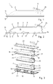
- Figur 1
- einen erfindungsgemäßen Abgaskrümmer in einer Seitenansicht;
- Figur 2
- den Abgaskrümmer gemäß der Darstellung der
Figur 1 in einem Längsschnitt; - Figur 3
- den Abgaskrümmer mit einer explosionsartig auseinandergezogenen Darstellung seiner Bauteile;
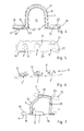
- Figur 4
- einen Querschnitt durch den Abgaskrümmer;
- Figur 5
- eine Ansicht auf den Abgaskrümmer von unten;
- Figur 6
- das Leitblech eines Abgaskrümmers in einer perspektivischen Darstellung und
- Figur 7
- einen Querschnitt durch den Abgaskrümmer im Bereich des Austrittsflanschs.
- Anhand der Darstellungen der
Figuren 1 bis 7 ist ein erfindungsgemäßer Abgaskrümmer 1 für eine Abgasanlage eines Verbrennungsmotors beschrieben. Der Abgaskrümmer 1 wird an einem hier nicht dargestellten Zylinderkopf eines Verbrennungsmotors in einen Kraftfahrzeug angebracht bzw. montiert. - Der Abgaskrümmer 1 umfasst ein Gehäuse 2, welches mehrere Einlassöffnungen 3, 4, 5 und eine Auslassöffnung 6 aufweist. Das Gehäuse 2 besteht aus einer Innenschale 7 und einer Außenschale 8. Die Außenschale 8 umgibt die Innenschale 7 unter Ausbildung eines Spalts 9. Zylinderkopfseitig der Innenschale 7 ist ein Leitblech 10 angeordnet. An dem Leitblech 10 sind die Einlassöffnungen 3, 4, 5 ausgebildet. Umfangsseitig der Einlassöffnungen 3, 4, 5 sind Leitorgane 11, 12, 13 in Form von Ausstellungen aus dem Leitblech 10 nach innen in das Gehäuse 2 ausgestellt. Die Leitorgane 11, 12, 13 führen das aus den Zylinderauslässen kommende über die Einlassöffnungen 3, 4, 5 einströmende Abgas im Innenraum 14 der Innenschale 7 zusammen und leiten den Abgasström gerichtet in Richtung der Auslassöffnung 6.
- Die Außenschale 8 weist an ihrem zylinderkopfseitigen Rand 15 einen nach außen umgestellten umlaufenden Flansch 16 auf. Der Flansch 16 liegt am Leitblech 10 an und ist mit dem Leitblech 10 umlaufend stoffschlüssig über eine Schweißnaht 17 gasdicht gefügt. Insbesondere erfolgt die Fügung thermisch mittels Laserschweißen.
- Auf der dem Leitblech 10 gegenüberliegenden Außenseite 18 des Flanschs 16 ist ein Bundkörper 19 angeordnet. Der Bundkörper 19 ist einstückig ausgeführt und verläuft in sich geschlossen entlang des Flanschs 16 um die Außenschale 8 herum. Am Flansch 16 kann der Bundkörper 19 fixiert sein, insbesondere schweißtechnisch geheftet sein. Möglich ist auch eine umlaufende durchgehende Verschweißung zwischen Bundkörper 19 und Flansch 16.
- Im Spalt 9 zwischen Innenschale 7 und Außenschale 8 ist ein Dämmmaterial 20 eingegliedert. Das Dämmmaterial 20 ist als vorkonfektionierter schalenförmiger Dämmmattenkörper 21 ausgeführt. Der Dämmmattenkörper 21 besitzt eine an die Innenkontur bzw. Außenkontur der Außenschale 8 bzw. Innenschale 7 angepasste Konfiguration. Das Dämmmaterial 20 hat sowohl schalldämmende als auch thermisch isolierende Eigenschaften.
- Die Leitorgane 11, 12, 13 sind materialeinheitlich einstückig aus dem Leitblech 10 ausgestellt. Durch die Kontur der Leitorgane 11, 12, 13 verjüngen sich die Einlassöffnungen 3, 4, 5 vom Leitblech 10 zum Ende der Leitorgange 11, 12, 13 hin. Dies hat positiven Einfluss auf die Strömungsverhältnisse in der Innenschale 7 und die gerichtete Abgasströmung bei der Umlenkung von den Einlassöffnungen 3, 4, 5 zu der Auslassöffnung 6.
- Die
Figur 4 verdeutlicht, dass die Innenschale 7 an ihrem zylinderkopfseitigen Rand 22 einen nach außen umgestellten Kragen 23 besitzt. Mit dem Kragen 23 steht die Innenschale 7 auf dem Leitblech 10 auf. Dies wird auch in derFigur 7 deutlich. Man erkennt ferner, dass die Leitorgane 11, 12, 13 nach innen in die Innenschale 7 ragen. In derFigur 4 erkennt man des Weiteren, dass das Leitorgan 13 die Innenschale 7 innen kontaktiert, so dass hier eine Lageorientierung der Innenschale 7 durch das Leitorgan 13 erfolgt. - Die Außenschale 8 weist einen Auslassstutzen 24 auf. Die Auslassöffnung 6 im Auslassstutzen 24 der Außenschale 8. Am Auslassstutzen 24 ist ein Austrittsflansch 25 gasdicht stoffschlüssig gefügt, insbesondere dicht verschweißt. Der Austrittsflansch 25 dient zur Verbindung des Abgaskrümmers 1 mit nachgeschalteten Bauteilkomponenten der Abgasanlage.
- Insbesondere in der
Figur 7 erkennt man, dass auch die Innenschale 7 einen Auslassstutzen 26 aufweist. Der Auslassstutzen 26 der Innenschale 7 liegt innen im Auslassstutzen 24 der Außenschale 8 an. Insbesondere liegt der Auslassstutzen 26 der Innenschale 7 dicht am Innenumfang des Auslassstutzens 24 der Außenschale 8 an, jedoch beweglich, so dass er sich entlang des Innenumfangs verschieben kann. - Im Bundkörper 19, im Flansch 16 und im Leitblech 10 sind zueinander korrespondierende Montageöffnungen 27 vorgesehen. Über Befestigungsmitteln in Form von Schraubbolzen, die durch die Montagelöcher 27 geführt und in Gewindebohrungen im Zylinderkopf geschraubt werden, kann der Abgaskrümmer 1 am Zylinderkopf einer Brennkraftmaschine festgelegt und verspannt werden.
- Der Abgaskrümmer 1 zeichnet sich durch sein geringes Gewicht infolge seiner leichten Bauweise aus. Die Außenschale 8 und das Leitblech 10 bilden das Außensystem, welches gasdicht durch Schweißung verbunden ist. Durch eine Lenkung bzw. gerichtete Führung des Abgasstroms aus dem Zylinderkopf in die Innenschale 7 mittels der Leitorgane 11, 12, 13 im Leitblech 10 wird ein geringer Gegendruck erzeugt bzw. der Abgasgegendruck wird reduziert.
-
- 1
- - Abgaskrümmer
- 2
- - Gehäuse
- 3
- - Einlassöffnung
- 4
- - Einlassöffnung
- 5
- - Einlassöffnung
- 6
- - Auslassöffnung
- 7
- - Innenschale
- 8
- - Außenschale
- 9
- - Spalt
- 10
- - Leitblech
- 11
- - Leitorgan
- 12
- - Leitorgan
- 13
- - Leitorgan
- 14
- - Innenraum von 7
- 15
- - Rand von 8
- 16
- - Flansch
- 17
- - Schweißnaht
- 18
- - Außenseite von 16
- 19
- - Bundkörper
- 20
- - Dämmmaterial
- 21
- - Dämmmattenkörper
- 22
- - Rand von 7
- 23
- - Kragen
- 24
- - Auslassstutzen von 8
- 25
- - Austrittsflansch
- 26
- - Auslassstutzen von 7
- 27
- - Montageöffnung
Claims (9)
- Abgaskrümmer zur Anbringung an einem Zylinderkopf einer Brennkraftmaschine, mit einem Gehäuse (2), welches mehrere Einlassöffnungen (3, 4, 5) und eine Auslassöffnung (6) aufweist und welches eine Innenschale (7) und eine Außenschale (8) umfasst, wobei die Außenschale (8) die Innenschale (7) unter Ausbildung eines Spalts (9) umgibt und der Innenschale (7) zylinderkopfseitig ein Leitblech (10) zugeordnet ist, in welchem die Einlassöffnungen (3, 4, 5) vorgesehen sind, wobei umfangsseitig der Einlassöffnungen (3, 4, 5) am Leitblech (10) Leitorgane (11, 12, 13) ausgebildet sind und die Außenschale (8) an ihrem zylinderkopfseitigen Rand (15) einen nach außen umgestellten Flansch (16) aufweist, wobei der Flansch (16) am Leitblech (10) anliegt und mit dem Leitblech (10) stoffschlüssig gasdicht gefügt ist, dadurch gekennzeichnet, dass die Innenschale (7) zylinderkopfseitig an dem Leitblech (10) anliegt, wobei die Innenschale (7) schwimmend in der Außenschale (8) angeordnet ist und auf der dem Leitblech (10) gegenüber liegenden Außenseite (18) des Flanschs (16) ein Bundkörper (19) angeordnet ist.
- Abgaskrümmer nach Anspruch 1, dadurch gekennzeichnet, dass der Flansch (16) der Außenschale (8) und das Leitblech (10) miteinander verschweißt sind.
- Abgaskrümmer nach Anspruch 1 oder 2, dadurch gekennzeichnet, dass der Bundkörper (19) am Flansch (16) fixiert ist.
- Abgaskrümmer nach wenigstens einem der Ansprüche 1 bis 3, dadurch gekennzeichnet, dass der Bundkörper (19) einstückig und entlang des Flanschs (16) umlaufend ausgeführt ist.
- Abgaskrümmer nach wenigstens einem der Ansprüche 1 bis 4, dadurch gekennzeichnet, dass im Bundkörper (19), im Flansch (16) und im Leitblech (10) zueinander korrespondierende Montagelöcher (27) vorgesehen sind.
- Abgaskrümmer nach wenigstens einem der Ansprüche 1 bis 4, dadurch gekennzeichnet, dass in dem Spalt (9) zwischen Innenschale (7) und Außenschale (9) ein Dämmmaterial (20) eingegliedert ist.
- Abgaskrümmer nach wenigstens einem der Ansprüche 1 bis 6, dadurch gekennzeichnet, dass die Leitorgane (11, 12, 13) materialeinheitlich einstückig aus dem Leitblech (10) ausgestellt sind.
- Abgaskrümmer nach wenigstens einem der Ansprüche 1 bis 7, dadurch gekennzeichnet, dass die Außenschale (8) einen Auslassstutzen (24) aufweist und ein Austrittsflansch (25) mit dem Auslassstutzen (24) gasdicht stoffschlüssig gefügt ist.
- Abgaskrümmer nach Anspruch 8, dadurch gekennzeichnet, dass die Innenschale (7) einen Auslassstutzen (26) aufweist und der Auslassstutzen (26) der Innenschale (7) in den Auslassstutzen (24) der Außenschale (8) ragt.
Applications Claiming Priority (1)
| Application Number | Priority Date | Filing Date | Title |
|---|---|---|---|
| DE102014105656.6A DE102014105656B4 (de) | 2014-04-22 | 2014-04-22 | Abgaskrümmer |
Publications (2)
| Publication Number | Publication Date |
|---|---|
| EP2937539A1 true EP2937539A1 (de) | 2015-10-28 |
| EP2937539B1 EP2937539B1 (de) | 2016-10-12 |
Family
ID=52629481
Family Applications (1)
| Application Number | Title | Priority Date | Filing Date |
|---|---|---|---|
| EP15158493.5A Not-in-force EP2937539B1 (de) | 2014-04-22 | 2015-03-10 | Abgaskrümmer |
Country Status (5)
| Country | Link |
|---|---|
| US (1) | US9410470B2 (de) |
| EP (1) | EP2937539B1 (de) |
| CN (1) | CN105041439B (de) |
| DE (1) | DE102014105656B4 (de) |
| ES (1) | ES2603103T3 (de) |
Families Citing this family (3)
| Publication number | Priority date | Publication date | Assignee | Title |
|---|---|---|---|---|
| CN116291837A (zh) * | 2018-05-15 | 2023-06-23 | 康明斯公司 | 双壁集成凸缘接头 |
| US11421577B2 (en) * | 2020-02-25 | 2022-08-23 | Divergent Technologies, Inc. | Exhaust headers with integrated heat shielding and thermal syphoning |
| DE102021119216A1 (de) * | 2021-07-26 | 2023-01-26 | Purem GmbH | Schalldämpfer |
Citations (11)
| Publication number | Priority date | Publication date | Assignee | Title |
|---|---|---|---|---|
| US5729975A (en) | 1996-06-11 | 1998-03-24 | Benteler Automotive Corporation | Semi-airgap manifold formation |
| EP0849445A1 (de) * | 1996-12-20 | 1998-06-24 | Zeuna-Stärker Gmbh & Co Kg | Abgassammler und Verfahren zu seiner Herstellung |
| JP2001303949A (ja) * | 2000-04-26 | 2001-10-31 | Futaba Industrial Co Ltd | エギゾーストマニホルド |
| DE10102637A1 (de) | 2001-01-20 | 2002-07-25 | Bayerische Motoren Werke Ag | Abgaskrümmer zur Abgasabführung aus einem Verbrennungsmotor |
| US20020174650A1 (en) * | 2001-05-23 | 2002-11-28 | Gerd Durr | Exhaust manifold |
| EP1206631B1 (de) | 1999-08-05 | 2005-02-02 | Hans A. Haerle | Abgaskrümmer |
| DE10359073A1 (de) | 2003-12-17 | 2005-07-21 | Daimlerchrysler Ag | Abgaskrümmer |
| DE10359062A1 (de) | 2003-12-17 | 2005-07-21 | Daimlerchrysler Ag | Haubenkrümmer |
| EP1389267B1 (de) | 2001-01-29 | 2006-03-29 | Hans A. Haerle | Abgaskrümmer |
| DE102006056073A1 (de) * | 2006-11-28 | 2008-05-29 | Arvinmeritor Emissions Technologies Gmbh | Krümmer für eine Abgasanlage |
| EP2207950B1 (de) | 2007-11-09 | 2011-05-18 | Heinrich Gillet GmbH | Abgaskrümmer für brennkraftmaschinen |
Family Cites Families (17)
| Publication number | Priority date | Publication date | Assignee | Title |
|---|---|---|---|---|
| US4537027A (en) * | 1983-11-21 | 1985-08-27 | Apx Group, Inc. | Hybrid exhaust manifold |
| US4850189A (en) * | 1987-10-14 | 1989-07-25 | Arvin Industries, Inc. | Manifold baffle system |
| JPH09125948A (ja) * | 1995-10-31 | 1997-05-13 | Toshiomi Hayashi | エンジンの排気系配管類の組立方法及び組立構造 |
| US7272927B2 (en) * | 2003-11-07 | 2007-09-25 | Heinrich Gillet Gmbh | Air gap-insulated exhaust manifold for internal combustion engines |
| DE10352960B4 (de) | 2003-11-13 | 2006-06-14 | Benteler Automobiltechnik Gmbh | Gehäuseanordnung für den Turbolader einer Brennkraftmaschine |
| DE102005011639B4 (de) * | 2005-03-14 | 2015-10-22 | Faurecia Emissions Control Technologies, Germany Gmbh | Luftspaltisolierter Abgaskrümmer |
| DE102008052552B4 (de) | 2008-10-21 | 2015-06-11 | Benteler Automobiltechnik Gmbh | Turbinengehäuse und Verfahren zu seiner Herstellung |
| CN201367937Y (zh) * | 2009-03-03 | 2009-12-23 | 吉林长城机械制造有限公司 | 矿用防爆柴油机绝热式排气歧管 |
| DE102009030482A1 (de) | 2009-06-24 | 2011-03-24 | Benteler Automobiltechnik Gmbh | Abgasbaugruppe |
| DE102009031980C5 (de) | 2009-07-06 | 2017-12-14 | Benteler Automobiltechnik Gmbh | Verfahren und Vorrichtung zur Befestigung eines Abgaskonvertermoduls |
| DE102009042260B4 (de) | 2009-09-22 | 2015-12-10 | Benteler Automobiltechnik Gmbh | Abgasturbolader |
| DE102009058047A1 (de) | 2009-12-14 | 2011-06-16 | Benteler Automobiltechnik Gmbh | Abgaskrümmer mit Leitblech |
| DE102010005761A1 (de) | 2010-01-25 | 2011-07-28 | Benteler Automobiltechnik GmbH, 33102 | Abgasbaugruppe |
| DE102010019404B4 (de) | 2010-05-04 | 2012-01-05 | Benteler Automobiltechnik Gmbh | Verfahren zur Herstellung eines Turboladergehäuses |
| DE102010021114A1 (de) | 2010-05-20 | 2011-11-24 | Benteler Automobiltechnik Gmbh | Abgasturbolader |
| DE102010022218A1 (de) | 2010-05-21 | 2011-11-24 | Benteler Automobiltechnik Gmbh | Abgasturbolader |
| DE102011050506B4 (de) | 2011-05-19 | 2013-04-18 | Benteler Automobiltechnik Gmbh | Abgasturbolader |
-
2014
- 2014-04-22 DE DE102014105656.6A patent/DE102014105656B4/de not_active Expired - Fee Related
-
2015
- 2015-03-10 ES ES15158493.5T patent/ES2603103T3/es active Active
- 2015-03-10 EP EP15158493.5A patent/EP2937539B1/de not_active Not-in-force
- 2015-04-20 US US14/691,102 patent/US9410470B2/en not_active Expired - Fee Related
- 2015-04-22 CN CN201510192411.XA patent/CN105041439B/zh not_active Expired - Fee Related
Patent Citations (11)
| Publication number | Priority date | Publication date | Assignee | Title |
|---|---|---|---|---|
| US5729975A (en) | 1996-06-11 | 1998-03-24 | Benteler Automotive Corporation | Semi-airgap manifold formation |
| EP0849445A1 (de) * | 1996-12-20 | 1998-06-24 | Zeuna-Stärker Gmbh & Co Kg | Abgassammler und Verfahren zu seiner Herstellung |
| EP1206631B1 (de) | 1999-08-05 | 2005-02-02 | Hans A. Haerle | Abgaskrümmer |
| JP2001303949A (ja) * | 2000-04-26 | 2001-10-31 | Futaba Industrial Co Ltd | エギゾーストマニホルド |
| DE10102637A1 (de) | 2001-01-20 | 2002-07-25 | Bayerische Motoren Werke Ag | Abgaskrümmer zur Abgasabführung aus einem Verbrennungsmotor |
| EP1389267B1 (de) | 2001-01-29 | 2006-03-29 | Hans A. Haerle | Abgaskrümmer |
| US20020174650A1 (en) * | 2001-05-23 | 2002-11-28 | Gerd Durr | Exhaust manifold |
| DE10359073A1 (de) | 2003-12-17 | 2005-07-21 | Daimlerchrysler Ag | Abgaskrümmer |
| DE10359062A1 (de) | 2003-12-17 | 2005-07-21 | Daimlerchrysler Ag | Haubenkrümmer |
| DE102006056073A1 (de) * | 2006-11-28 | 2008-05-29 | Arvinmeritor Emissions Technologies Gmbh | Krümmer für eine Abgasanlage |
| EP2207950B1 (de) | 2007-11-09 | 2011-05-18 | Heinrich Gillet GmbH | Abgaskrümmer für brennkraftmaschinen |
Also Published As
| Publication number | Publication date |
|---|---|
| CN105041439B (zh) | 2017-12-19 |
| ES2603103T3 (es) | 2017-02-23 |
| US20150300235A1 (en) | 2015-10-22 |
| DE102014105656A1 (de) | 2015-10-22 |
| US9410470B2 (en) | 2016-08-09 |
| EP2937539B1 (de) | 2016-10-12 |
| CN105041439A (zh) | 2015-11-11 |
| DE102014105656B4 (de) | 2017-02-02 |
Similar Documents
| Publication | Publication Date | Title |
|---|---|---|
| EP1270891B1 (de) | Vorrichtung zur Befestigung eines Abgasturboladers an einem Abgaskrümmer einer Brennkraftmaschine | |
| DE69613250T2 (de) | Wabenförmige Katalysatoreinrichtung | |
| EP1122421B1 (de) | Saugrohr mit integrierter Abgasrückführung | |
| EP1196687B1 (de) | Fluideinleitung für ein heisses fluid in einer hohlraumstruktur | |
| DE10054006A1 (de) | Luftspaltisolierter Abgaskrümmer für eine Brennkraftmaschine | |
| EP2267285B1 (de) | Abgasbaugruppe | |
| EP2522824B1 (de) | Abgasanlagenkomponente | |
| EP2333265B1 (de) | Abgaskrümmer mit Leitblech | |
| DE10125121A1 (de) | Abgaskrümmer | |
| EP2494179B1 (de) | Abgaswärmetauscher | |
| DE102009025054A1 (de) | Turbinengehäuse | |
| WO2017144159A1 (de) | Regelvorrichtung für einen abgasturbolader | |
| EP2937539B1 (de) | Abgaskrümmer | |
| EP2921670B1 (de) | Abgaskrümmer für eine Abgasanlage eines Verbrennungsmotors | |
| EP3001004B1 (de) | Abgaskrümmer | |
| EP1260697B1 (de) | Aufgeladene Brennkraftmaschine | |
| EP1389267B1 (de) | Abgaskrümmer | |
| DE112007000864B4 (de) | Abgaskrümmer-Anordnung | |
| DE3631312C1 (de) | Einrichtung zur Halterung von Abgasleitungen | |
| EP1591636A1 (de) | Luftspaltisolierter Abgaskrümmer | |
| WO2006119824A1 (de) | Luftspaltisolierte fahrzeugabgasleitung | |
| DE3243631A1 (de) | Abgasschalldaempfer | |
| DE10359073B4 (de) | Abgaskrümmer | |
| DE102004051680C5 (de) | Anordnung zur Befestigung eines Abgaskrümmers | |
| EP1840350B1 (de) | Verkleidungsvorrichtung, insbesondere für Abgasrohre von Aggregaten |
Legal Events
| Date | Code | Title | Description |
|---|---|---|---|
| PUAI | Public reference made under article 153(3) epc to a published international application that has entered the european phase |
Free format text: ORIGINAL CODE: 0009012 |
|
| AK | Designated contracting states |
Kind code of ref document: A1 Designated state(s): AL AT BE BG CH CY CZ DE DK EE ES FI FR GB GR HR HU IE IS IT LI LT LU LV MC MK MT NL NO PL PT RO RS SE SI SK SM TR |
|
| AX | Request for extension of the european patent |
Extension state: BA ME |
|
| 17P | Request for examination filed |
Effective date: 20151027 |
|
| GRAP | Despatch of communication of intention to grant a patent |
Free format text: ORIGINAL CODE: EPIDOSNIGR1 |
|
| INTG | Intention to grant announced |
Effective date: 20160607 |
|
| GRAS | Grant fee paid |
Free format text: ORIGINAL CODE: EPIDOSNIGR3 |
|
| GRAA | (expected) grant |
Free format text: ORIGINAL CODE: 0009210 |
|
| AK | Designated contracting states |
Kind code of ref document: B1 Designated state(s): AL AT BE BG CH CY CZ DE DK EE ES FI FR GB GR HR HU IE IS IT LI LT LU LV MC MK MT NL NO PL PT RO RS SE SI SK SM TR |
|
| REG | Reference to a national code |
Ref country code: GB Ref legal event code: FG4D Free format text: NOT ENGLISH |
|
| REG | Reference to a national code |
Ref country code: CH Ref legal event code: EP |
|
| REG | Reference to a national code |
Ref country code: AT Ref legal event code: REF Ref document number: 836733 Country of ref document: AT Kind code of ref document: T Effective date: 20161015 |
|
| REG | Reference to a national code |
Ref country code: IE Ref legal event code: FG4D Free format text: LANGUAGE OF EP DOCUMENT: GERMAN |
|
| REG | Reference to a national code |
Ref country code: DE Ref legal event code: R096 Ref document number: 502015000221 Country of ref document: DE |
|
| REG | Reference to a national code |
Ref country code: LT Ref legal event code: MG4D |
|
| REG | Reference to a national code |
Ref country code: NL Ref legal event code: MP Effective date: 20161012 |
|
| REG | Reference to a national code |
Ref country code: ES Ref legal event code: FG2A Ref document number: 2603103 Country of ref document: ES Kind code of ref document: T3 Effective date: 20170223 |
|
| PG25 | Lapsed in a contracting state [announced via postgrant information from national office to epo] |
Ref country code: LV Free format text: LAPSE BECAUSE OF FAILURE TO SUBMIT A TRANSLATION OF THE DESCRIPTION OR TO PAY THE FEE WITHIN THE PRESCRIBED TIME-LIMIT Effective date: 20161012 |
|
| PG25 | Lapsed in a contracting state [announced via postgrant information from national office to epo] |
Ref country code: SE Free format text: LAPSE BECAUSE OF FAILURE TO SUBMIT A TRANSLATION OF THE DESCRIPTION OR TO PAY THE FEE WITHIN THE PRESCRIBED TIME-LIMIT Effective date: 20161012 Ref country code: GR Free format text: LAPSE BECAUSE OF FAILURE TO SUBMIT A TRANSLATION OF THE DESCRIPTION OR TO PAY THE FEE WITHIN THE PRESCRIBED TIME-LIMIT Effective date: 20170113 Ref country code: LT Free format text: LAPSE BECAUSE OF FAILURE TO SUBMIT A TRANSLATION OF THE DESCRIPTION OR TO PAY THE FEE WITHIN THE PRESCRIBED TIME-LIMIT Effective date: 20161012 Ref country code: NO Free format text: LAPSE BECAUSE OF FAILURE TO SUBMIT A TRANSLATION OF THE DESCRIPTION OR TO PAY THE FEE WITHIN THE PRESCRIBED TIME-LIMIT Effective date: 20170112 |
|
| PG25 | Lapsed in a contracting state [announced via postgrant information from national office to epo] |
Ref country code: RS Free format text: LAPSE BECAUSE OF FAILURE TO SUBMIT A TRANSLATION OF THE DESCRIPTION OR TO PAY THE FEE WITHIN THE PRESCRIBED TIME-LIMIT Effective date: 20161012 Ref country code: HR Free format text: LAPSE BECAUSE OF FAILURE TO SUBMIT A TRANSLATION OF THE DESCRIPTION OR TO PAY THE FEE WITHIN THE PRESCRIBED TIME-LIMIT Effective date: 20161012 Ref country code: PL Free format text: LAPSE BECAUSE OF FAILURE TO SUBMIT A TRANSLATION OF THE DESCRIPTION OR TO PAY THE FEE WITHIN THE PRESCRIBED TIME-LIMIT Effective date: 20161012 Ref country code: NL Free format text: LAPSE BECAUSE OF FAILURE TO SUBMIT A TRANSLATION OF THE DESCRIPTION OR TO PAY THE FEE WITHIN THE PRESCRIBED TIME-LIMIT Effective date: 20161012 Ref country code: FI Free format text: LAPSE BECAUSE OF FAILURE TO SUBMIT A TRANSLATION OF THE DESCRIPTION OR TO PAY THE FEE WITHIN THE PRESCRIBED TIME-LIMIT Effective date: 20161012 Ref country code: IS Free format text: LAPSE BECAUSE OF FAILURE TO SUBMIT A TRANSLATION OF THE DESCRIPTION OR TO PAY THE FEE WITHIN THE PRESCRIBED TIME-LIMIT Effective date: 20170212 Ref country code: PT Free format text: LAPSE BECAUSE OF FAILURE TO SUBMIT A TRANSLATION OF THE DESCRIPTION OR TO PAY THE FEE WITHIN THE PRESCRIBED TIME-LIMIT Effective date: 20170213 |
|
| REG | Reference to a national code |
Ref country code: DE Ref legal event code: R097 Ref document number: 502015000221 Country of ref document: DE |
|
| PG25 | Lapsed in a contracting state [announced via postgrant information from national office to epo] |
Ref country code: RO Free format text: LAPSE BECAUSE OF FAILURE TO SUBMIT A TRANSLATION OF THE DESCRIPTION OR TO PAY THE FEE WITHIN THE PRESCRIBED TIME-LIMIT Effective date: 20161012 Ref country code: DK Free format text: LAPSE BECAUSE OF FAILURE TO SUBMIT A TRANSLATION OF THE DESCRIPTION OR TO PAY THE FEE WITHIN THE PRESCRIBED TIME-LIMIT Effective date: 20161012 Ref country code: SK Free format text: LAPSE BECAUSE OF FAILURE TO SUBMIT A TRANSLATION OF THE DESCRIPTION OR TO PAY THE FEE WITHIN THE PRESCRIBED TIME-LIMIT Effective date: 20161012 Ref country code: EE Free format text: LAPSE BECAUSE OF FAILURE TO SUBMIT A TRANSLATION OF THE DESCRIPTION OR TO PAY THE FEE WITHIN THE PRESCRIBED TIME-LIMIT Effective date: 20161012 Ref country code: CZ Free format text: LAPSE BECAUSE OF FAILURE TO SUBMIT A TRANSLATION OF THE DESCRIPTION OR TO PAY THE FEE WITHIN THE PRESCRIBED TIME-LIMIT Effective date: 20161012 |
|
| PLBE | No opposition filed within time limit |
Free format text: ORIGINAL CODE: 0009261 |
|
| STAA | Information on the status of an ep patent application or granted ep patent |
Free format text: STATUS: NO OPPOSITION FILED WITHIN TIME LIMIT |
|
| PG25 | Lapsed in a contracting state [announced via postgrant information from national office to epo] |
Ref country code: SM Free format text: LAPSE BECAUSE OF FAILURE TO SUBMIT A TRANSLATION OF THE DESCRIPTION OR TO PAY THE FEE WITHIN THE PRESCRIBED TIME-LIMIT Effective date: 20161012 Ref country code: IT Free format text: LAPSE BECAUSE OF FAILURE TO SUBMIT A TRANSLATION OF THE DESCRIPTION OR TO PAY THE FEE WITHIN THE PRESCRIBED TIME-LIMIT Effective date: 20161012 Ref country code: BG Free format text: LAPSE BECAUSE OF FAILURE TO SUBMIT A TRANSLATION OF THE DESCRIPTION OR TO PAY THE FEE WITHIN THE PRESCRIBED TIME-LIMIT Effective date: 20170112 |
|
| 26N | No opposition filed |
Effective date: 20170713 |
|
| PG25 | Lapsed in a contracting state [announced via postgrant information from national office to epo] |
Ref country code: MC Free format text: LAPSE BECAUSE OF FAILURE TO SUBMIT A TRANSLATION OF THE DESCRIPTION OR TO PAY THE FEE WITHIN THE PRESCRIBED TIME-LIMIT Effective date: 20161012 Ref country code: SI Free format text: LAPSE BECAUSE OF FAILURE TO SUBMIT A TRANSLATION OF THE DESCRIPTION OR TO PAY THE FEE WITHIN THE PRESCRIBED TIME-LIMIT Effective date: 20161012 |
|
| REG | Reference to a national code |
Ref country code: IE Ref legal event code: MM4A |
|
| REG | Reference to a national code |
Ref country code: FR Ref legal event code: ST Effective date: 20171130 |
|
| PG25 | Lapsed in a contracting state [announced via postgrant information from national office to epo] |
Ref country code: LU Free format text: LAPSE BECAUSE OF NON-PAYMENT OF DUE FEES Effective date: 20170310 Ref country code: FR Free format text: LAPSE BECAUSE OF NON-PAYMENT OF DUE FEES Effective date: 20170331 |
|
| PG25 | Lapsed in a contracting state [announced via postgrant information from national office to epo] |
Ref country code: IE Free format text: LAPSE BECAUSE OF NON-PAYMENT OF DUE FEES Effective date: 20170310 |
|
| REG | Reference to a national code |
Ref country code: BE Ref legal event code: MM Effective date: 20170331 |
|
| PG25 | Lapsed in a contracting state [announced via postgrant information from national office to epo] |
Ref country code: BE Free format text: LAPSE BECAUSE OF NON-PAYMENT OF DUE FEES Effective date: 20170331 |
|
| PG25 | Lapsed in a contracting state [announced via postgrant information from national office to epo] |
Ref country code: MT Free format text: LAPSE BECAUSE OF FAILURE TO SUBMIT A TRANSLATION OF THE DESCRIPTION OR TO PAY THE FEE WITHIN THE PRESCRIBED TIME-LIMIT Effective date: 20161012 |
|
| REG | Reference to a national code |
Ref country code: CH Ref legal event code: PL |
|
| PG25 | Lapsed in a contracting state [announced via postgrant information from national office to epo] |
Ref country code: CH Free format text: LAPSE BECAUSE OF NON-PAYMENT OF DUE FEES Effective date: 20180331 Ref country code: LI Free format text: LAPSE BECAUSE OF NON-PAYMENT OF DUE FEES Effective date: 20180331 |
|
| PG25 | Lapsed in a contracting state [announced via postgrant information from national office to epo] |
Ref country code: HU Free format text: LAPSE BECAUSE OF FAILURE TO SUBMIT A TRANSLATION OF THE DESCRIPTION OR TO PAY THE FEE WITHIN THE PRESCRIBED TIME-LIMIT; INVALID AB INITIO Effective date: 20150310 |
|
| PG25 | Lapsed in a contracting state [announced via postgrant information from national office to epo] |
Ref country code: CY Free format text: LAPSE BECAUSE OF FAILURE TO SUBMIT A TRANSLATION OF THE DESCRIPTION OR TO PAY THE FEE WITHIN THE PRESCRIBED TIME-LIMIT Effective date: 20161012 |
|
| PG25 | Lapsed in a contracting state [announced via postgrant information from national office to epo] |
Ref country code: MK Free format text: LAPSE BECAUSE OF FAILURE TO SUBMIT A TRANSLATION OF THE DESCRIPTION OR TO PAY THE FEE WITHIN THE PRESCRIBED TIME-LIMIT Effective date: 20161012 |
|
| PG25 | Lapsed in a contracting state [announced via postgrant information from national office to epo] |
Ref country code: TR Free format text: LAPSE BECAUSE OF FAILURE TO SUBMIT A TRANSLATION OF THE DESCRIPTION OR TO PAY THE FEE WITHIN THE PRESCRIBED TIME-LIMIT Effective date: 20161012 |
|
| PG25 | Lapsed in a contracting state [announced via postgrant information from national office to epo] |
Ref country code: AL Free format text: LAPSE BECAUSE OF FAILURE TO SUBMIT A TRANSLATION OF THE DESCRIPTION OR TO PAY THE FEE WITHIN THE PRESCRIBED TIME-LIMIT Effective date: 20161012 |
|
| REG | Reference to a national code |
Ref country code: AT Ref legal event code: MM01 Ref document number: 836733 Country of ref document: AT Kind code of ref document: T Effective date: 20200310 |
|
| PGFP | Annual fee paid to national office [announced via postgrant information from national office to epo] |
Ref country code: GB Payment date: 20210324 Year of fee payment: 7 |
|
| PG25 | Lapsed in a contracting state [announced via postgrant information from national office to epo] |
Ref country code: AT Free format text: LAPSE BECAUSE OF NON-PAYMENT OF DUE FEES Effective date: 20200310 |
|
| PGFP | Annual fee paid to national office [announced via postgrant information from national office to epo] |
Ref country code: ES Payment date: 20210525 Year of fee payment: 7 |
|
| GBPC | Gb: european patent ceased through non-payment of renewal fee |
Effective date: 20220310 |
|
| PG25 | Lapsed in a contracting state [announced via postgrant information from national office to epo] |
Ref country code: GB Free format text: LAPSE BECAUSE OF NON-PAYMENT OF DUE FEES Effective date: 20220310 |
|
| REG | Reference to a national code |
Ref country code: ES Ref legal event code: FD2A Effective date: 20230428 |
|
| PGFP | Annual fee paid to national office [announced via postgrant information from national office to epo] |
Ref country code: DE Payment date: 20230330 Year of fee payment: 9 |
|
| PG25 | Lapsed in a contracting state [announced via postgrant information from national office to epo] |
Ref country code: ES Free format text: LAPSE BECAUSE OF NON-PAYMENT OF DUE FEES Effective date: 20220311 |
|
| REG | Reference to a national code |
Ref country code: DE Ref legal event code: R119 Ref document number: 502015000221 Country of ref document: DE |
|
| PG25 | Lapsed in a contracting state [announced via postgrant information from national office to epo] |
Ref country code: DE Free format text: LAPSE BECAUSE OF NON-PAYMENT OF DUE FEES Effective date: 20241001 |
|
| PG25 | Lapsed in a contracting state [announced via postgrant information from national office to epo] |
Ref country code: DE Free format text: LAPSE BECAUSE OF NON-PAYMENT OF DUE FEES Effective date: 20241001 |