EP2933868B1 - Sekundärbatterie mit wasserfreier elektrolytlösung und verfahren zur herstellung einer sekundärbatterie mit wasserfreier elektrolytlösung - Google Patents
Sekundärbatterie mit wasserfreier elektrolytlösung und verfahren zur herstellung einer sekundärbatterie mit wasserfreier elektrolytlösung Download PDFInfo
- Publication number
- EP2933868B1 EP2933868B1 EP12890013.1A EP12890013A EP2933868B1 EP 2933868 B1 EP2933868 B1 EP 2933868B1 EP 12890013 A EP12890013 A EP 12890013A EP 2933868 B1 EP2933868 B1 EP 2933868B1
- Authority
- EP
- European Patent Office
- Prior art keywords
- aqueous electrolyte
- electrode
- electrolyte solution
- active material
- flame retardant
- Prior art date
- Legal status (The legal status is an assumption and is not a legal conclusion. Google has not performed a legal analysis and makes no representation as to the accuracy of the status listed.)
- Active
Links
Images




Classifications
-
- H—ELECTRICITY
- H01—ELECTRIC ELEMENTS
- H01M—PROCESSES OR MEANS, e.g. BATTERIES, FOR THE DIRECT CONVERSION OF CHEMICAL ENERGY INTO ELECTRICAL ENERGY
- H01M4/00—Electrodes
- H01M4/02—Electrodes composed of, or comprising, active material
- H01M4/13—Electrodes for accumulators with non-aqueous electrolyte, e.g. for lithium-accumulators; Processes of manufacture thereof
- H01M4/133—Electrodes based on carbonaceous material, e.g. graphite-intercalation compounds or CFx
-
- H—ELECTRICITY
- H01—ELECTRIC ELEMENTS
- H01M—PROCESSES OR MEANS, e.g. BATTERIES, FOR THE DIRECT CONVERSION OF CHEMICAL ENERGY INTO ELECTRICAL ENERGY
- H01M10/00—Secondary cells; Manufacture thereof
- H01M10/42—Methods or arrangements for servicing or maintenance of secondary cells or secondary half-cells
- H01M10/4235—Safety or regulating additives or arrangements in electrodes, separators or electrolyte
-
- H—ELECTRICITY
- H01—ELECTRIC ELEMENTS
- H01M—PROCESSES OR MEANS, e.g. BATTERIES, FOR THE DIRECT CONVERSION OF CHEMICAL ENERGY INTO ELECTRICAL ENERGY
- H01M10/00—Secondary cells; Manufacture thereof
- H01M10/05—Accumulators with non-aqueous electrolyte
- H01M10/052—Li-accumulators
- H01M10/0525—Rocking-chair batteries, i.e. batteries with lithium insertion or intercalation in both electrodes; Lithium-ion batteries
-
- H—ELECTRICITY
- H01—ELECTRIC ELEMENTS
- H01M—PROCESSES OR MEANS, e.g. BATTERIES, FOR THE DIRECT CONVERSION OF CHEMICAL ENERGY INTO ELECTRICAL ENERGY
- H01M10/00—Secondary cells; Manufacture thereof
- H01M10/05—Accumulators with non-aqueous electrolyte
- H01M10/056—Accumulators with non-aqueous electrolyte characterised by the materials used as electrolytes, e.g. mixed inorganic/organic electrolytes
- H01M10/0564—Accumulators with non-aqueous electrolyte characterised by the materials used as electrolytes, e.g. mixed inorganic/organic electrolytes the electrolyte being constituted of organic materials only
- H01M10/0566—Liquid materials
- H01M10/0567—Liquid materials characterised by the additives
-
- H—ELECTRICITY
- H01—ELECTRIC ELEMENTS
- H01M—PROCESSES OR MEANS, e.g. BATTERIES, FOR THE DIRECT CONVERSION OF CHEMICAL ENERGY INTO ELECTRICAL ENERGY
- H01M10/00—Secondary cells; Manufacture thereof
- H01M10/05—Accumulators with non-aqueous electrolyte
- H01M10/058—Construction or manufacture
-
- H—ELECTRICITY
- H01—ELECTRIC ELEMENTS
- H01M—PROCESSES OR MEANS, e.g. BATTERIES, FOR THE DIRECT CONVERSION OF CHEMICAL ENERGY INTO ELECTRICAL ENERGY
- H01M10/00—Secondary cells; Manufacture thereof
- H01M10/42—Methods or arrangements for servicing or maintenance of secondary cells or secondary half-cells
- H01M10/44—Methods for charging or discharging
-
- H—ELECTRICITY
- H01—ELECTRIC ELEMENTS
- H01M—PROCESSES OR MEANS, e.g. BATTERIES, FOR THE DIRECT CONVERSION OF CHEMICAL ENERGY INTO ELECTRICAL ENERGY
- H01M50/00—Constructional details or processes of manufacture of the non-active parts of electrochemical cells other than fuel cells, e.g. hybrid cells
- H01M50/50—Current conducting connections for cells or batteries
- H01M50/531—Electrode connections inside a battery casing
- H01M50/534—Electrode connections inside a battery casing characterised by the material of the leads or tabs
-
- H—ELECTRICITY
- H01—ELECTRIC ELEMENTS
- H01M—PROCESSES OR MEANS, e.g. BATTERIES, FOR THE DIRECT CONVERSION OF CHEMICAL ENERGY INTO ELECTRICAL ENERGY
- H01M2300/00—Electrolytes
- H01M2300/0017—Non-aqueous electrolytes
- H01M2300/0025—Organic electrolyte
-
- H—ELECTRICITY
- H01—ELECTRIC ELEMENTS
- H01M—PROCESSES OR MEANS, e.g. BATTERIES, FOR THE DIRECT CONVERSION OF CHEMICAL ENERGY INTO ELECTRICAL ENERGY
- H01M2300/00—Electrolytes
- H01M2300/0017—Non-aqueous electrolytes
- H01M2300/0025—Organic electrolyte
- H01M2300/0028—Organic electrolyte characterised by the solvent
- H01M2300/0037—Mixture of solvents
- H01M2300/004—Three solvents
-
- Y—GENERAL TAGGING OF NEW TECHNOLOGICAL DEVELOPMENTS; GENERAL TAGGING OF CROSS-SECTIONAL TECHNOLOGIES SPANNING OVER SEVERAL SECTIONS OF THE IPC; TECHNICAL SUBJECTS COVERED BY FORMER USPC CROSS-REFERENCE ART COLLECTIONS [XRACs] AND DIGESTS
- Y02—TECHNOLOGIES OR APPLICATIONS FOR MITIGATION OR ADAPTATION AGAINST CLIMATE CHANGE
- Y02E—REDUCTION OF GREENHOUSE GAS [GHG] EMISSIONS, RELATED TO ENERGY GENERATION, TRANSMISSION OR DISTRIBUTION
- Y02E60/00—Enabling technologies; Technologies with a potential or indirect contribution to GHG emissions mitigation
- Y02E60/10—Energy storage using batteries
-
- Y—GENERAL TAGGING OF NEW TECHNOLOGICAL DEVELOPMENTS; GENERAL TAGGING OF CROSS-SECTIONAL TECHNOLOGIES SPANNING OVER SEVERAL SECTIONS OF THE IPC; TECHNICAL SUBJECTS COVERED BY FORMER USPC CROSS-REFERENCE ART COLLECTIONS [XRACs] AND DIGESTS
- Y02—TECHNOLOGIES OR APPLICATIONS FOR MITIGATION OR ADAPTATION AGAINST CLIMATE CHANGE
- Y02P—CLIMATE CHANGE MITIGATION TECHNOLOGIES IN THE PRODUCTION OR PROCESSING OF GOODS
- Y02P70/00—Climate change mitigation technologies in the production process for final industrial or consumer products
- Y02P70/50—Manufacturing or production processes characterised by the final manufactured product
-
- Y—GENERAL TAGGING OF NEW TECHNOLOGICAL DEVELOPMENTS; GENERAL TAGGING OF CROSS-SECTIONAL TECHNOLOGIES SPANNING OVER SEVERAL SECTIONS OF THE IPC; TECHNICAL SUBJECTS COVERED BY FORMER USPC CROSS-REFERENCE ART COLLECTIONS [XRACs] AND DIGESTS
- Y10—TECHNICAL SUBJECTS COVERED BY FORMER USPC
- Y10T—TECHNICAL SUBJECTS COVERED BY FORMER US CLASSIFICATION
- Y10T29/00—Metal working
- Y10T29/49—Method of mechanical manufacture
- Y10T29/49002—Electrical device making
- Y10T29/49117—Conductor or circuit manufacturing
Definitions
- the present invention relates to a non-aqueous electrolyte secondary battery and a method for producing a non-aqueous electrolyte secondary battery.
- Lithium ion secondary batteries have attracted attention because of their high energy density and have been actively researched and developed.
- a conventional lithium ion secondary battery often uses a solution prepared by dissolving a lithium salt such as LiPF6 into a mixture solvent of cyclic carbonate such as ethylene carbonate (EC) or propylene carbonate (PC) and chain carbonate such as diethyl carbonate (DEC) or dimethyl carbonate (DMC) as an electrolyte solution.
- the non-aqueous electrolyte solution prepared by using these carbonates has a low flash point of about 30°C. Therefore, when an electrolyte solution leaks out by some accident in the presence of a fire source, there is a danger of a fire caused by the leaking electrolyte solution which catches fires.
- various techniques of raising a flashpoint of an electrolyte solution have been studied. For example, mixing a flame retardant into an electrolyte solution has been studied as one of techniques of raising a flashpoint of an electrolyte solution (see Patent Document 1, for example).
- CN 102 420 340 discloses a manufacturing method of a battery, which comprises the steps of injecting an electrolyte into a battery shell through a liquid injecting port, and when a stable solid electrolyte interfacial film is formed on the surface of a negative electrode of the battery, adding a flame-retardant additive to seal off the liquid injection port.
- US 2003/129498 A1 discloses a battery comprising a secondary cell that employs a non-aqueous electrolyte solution including a non-aqueous solvent and a salt, and a flame retardant material that is a liquid immiscible in the non-aqueous electrolyte solution.
- the non-aqueous electrolyte solution is formed by dissolving the salt in the non-aqueous solvent.
- the flame retardant material is preferably a halogen-containing compound.
- EP 2 330 675 A1 discloses a secondary battery having a positive pole comprising an oxide for storing and releasing lithium ions, a negative pole comprising a carbon material for storing and releasing lithium ions, and a non-flammable electrolyte solution.
- the electrolyte solution comprises 1.5 mol/L or more of a lithium salt, or 1.0 mol/L or more of a lithium salt and 20% by volume or more of a phosphate ester derivative.
- JP 2000 311717 A discloses a battery element contained by heat contraction films applying a compression force in the layered direction of the battery element.
- the battery element is formed by stacking a positive electrode, a negative electrode, and a non-fluid electrolyte layer in a plane shape.
- the heat contraction films are wound on the battery element, then heated and contracted.
- Polyethylene, polypropylene, polyvinyl chloride, or polystyrene can be used as material for the heat contraction films.
- a flash point of the electrolyte solution rises to enhance safety to fires.
- the flash point of the electrolyte solution might be lowered.
- the conventional non-aqueous electrolyte secondary battery using an electrolyte solution containing a flame retardant mixed therein has a problem such that various characteristics of the battery, especially life characteristics such as cycle characteristics and floating charge characteristics, are more significantly deteriorated than a battery not containing a flame retardant.
- the present invention has been accomplished to provide a non-aqueous electrolyte secondary battery that can suppress a drop in a flash point of an electrolyte solution even if the non-aqueous electrolyte secondary battery is used for a long time.
- the present invention as defined in claims 1 and 6 provides a non-aqueous electrolyte secondary battery comprising: an electrode body having a structure in which a positive electrode including a positive-electrode active material and a negative electrode including a negative-electrode active material are stacked with a separator interposed therebetween; a non-aqueous electrolyte solution containing a flame retardant; and an outer casing accommodating the electrode body and the non-aqueous electrolyte solution, wherein the non-aqueous electrolyte solution in the electrode body has a flame retardant concentration lower than a flame retardant concentration in a non-aqueous electrolyte solution between the electrode body and the outer casing.
- a non-aqueous electrolyte secondary battery comprises: an electrode body having a structure in which a positive electrode including a positive-electrode active material and a negative electrode including a negative-electrode active material are stacked with a separator interposed therebetween; a non-aqueous electrolyte solution containing a flame retardant; and an outer casing accommodating the electrode body and the non-aqueous electrolyte solution. Therefore, charges can be moved between the positive-electrode active material and the negative-electrode active material through the non-aqueous electrolyte solution, whereby the battery can be charged and discharged.
- the non-aqueous electrolyte secondary battery according to the present invention comprises a non-aqueous electrolyte solution containing a frame retardant. Therefore, a flash point of the non-aqueous electrolyte solution can be raised, whereby safety of the battery can be enhanced.
- the non-aqueous electrolyte solution in the electrode body has a flame retardant concentration lower than a flame retardant concentration in a non-aqueous electrolyte solution between the electrode body and the outer casing. This configuration can suppress the consumption of the flame retardant caused by an electrochemical reaction in the positive-electrode active material and the negative-electrode active material due to charging and discharging of the battery.
- the non-aqueous electrolyte solution in the electrode body has a flame retardant concentration lower than a flame retardant concentration in a non-aqueous electrolyte solution between the electrode body and the outer casing.
- This configuration can reduce an amount of the flame retardant to be inserted into a solid electrolyte interface film formed on the surface of the positive-electrode active material or the surface of the negative-electrode active material upon charging of the non-aqueous electrolyte secondary battery. With this, a reduction in battery capacity can be suppressed even with the repeated charging-discharging cycles of the non-aqueous electrolyte secondary battery, whereby battery life characteristics can be enhanced. This effect has been demonstrated by the experiment conducted by the present inventor.
- a non-aqueous electrolyte secondary battery comprises: an electrode body having a structure in which a positive electrode including a positive-electrode active material and a negative electrode including a negative-electrode active material are stacked with a separator interposed therebetween; a non-aqueous electrolyte solution containing a flame retardant; and an outer casing accommodating the electrode body and the non-aqueous electrolyte solution, wherein the non-aqueous electrolyte solution in the electrode body has a flame retardant concentration lower than a flame retardant concentration in a non-aqueous electrolyte solution between the electrode body and the outer casing.
- the non-aqueous electrolyte solution in the electrode body means here a non-aqueous electrolyte solution retained in the electrode body, i.e., a non-aqueous electrolyte solution in pores of electrode active material layers, a non-aqueous electrolyte solution in pores of a separator, a non-aqueous electrolyte solution in a gap between an electrode and a separator, and a non-aqueous electrolyte solution inside a fixing member such as a shrink tube holding electrodes together.
- a fixing member such as a shrink tube holding electrodes together.
- the non-aqueous electrolyte solution between the electrode body and the outer casing means an electrolyte solution present between an electrode body and an outer casing.
- a fixing member for fixing an electrode body such as a shrink tube
- a non-aqueous electrolyte solution between the electrode body and the outer casing means an electrolyte solution between the fixing member and the outer casing.
- the negative electrode includes a porous negative-electrode active material layer including the negative-electrode active material, and the non-aqueous electrolyte solution in the electrode body is a non-aqueous electrolyte solution in pores of the negative-electrode active material layer.
- This configuration can suppress a consumption of a flame retardant by an electrochemical reaction in the negative-electrode active material caused by charging and discharging of the battery.
- the non-aqueous electrolyte solution contains ethylene carbonate.
- an SEI Solid Electrolyte Interface serving as a solid electrolyte interface film can be formed on the surface of the negative-electrode active material with charging.
- the flame retardant is a phosphazene compound.
- the flash point of the non-aqueous electrolyte solution can be raised by the flame retardant.
- the negative-electrode active material is made of a carbon material such as graphite or hard carbon.
- lithium ions can be extracted and/or inserted into the carbon material, and therefore, the non-aqueous electrolyte secondary battery can be charged and discharged.
- This configuration also enables the formation of the solid electrolyte interface film on the surface of the carbon material with the charging of the non-aqueous electrolyte secondary battery.
- the non-aqueous electrolyte secondary battery according to the present embodiment further includes a shrink tube that bundles the electrode body.
- the shape of the electrode body can be stabilized.
- This configuration also prevents the flame retardant contained in the non-aqueous electrolyte solution outside of the shrink tube from being flown and diffused into the electrode body, thereby being capable of suppressing the consumption of the flame retardant with the electrochemical reaction in the electrode active material.
- the present invention also provides a method for producing a non-aqueous electrolyte secondary battery, the method comprising the steps of: impregnating a porous negative-electrode active material layer and a porous positive-electrode active material layer with a non-aqueous electrolyte solution by dipping an electrode body, which has a structure in which a negative electrode including the negative-electrode active material layer and a positive electrode including the positive-electrode active material layer are stacked with a separator interposed therebetween, into a non-aqueous electrolyte solution substantially free of a frame retardant; and placing a flame retardant and a non-aqueous electrolyte solution into an outer casing housing the positive electrode and the negative electrode, wherein the electrode body and the shrink tube prevent the flame retardant contained in the non-aqueous electrolyte solution outside of the shrink tube from being flown and diffused into the electrode body.
- the method for producing a non-aqueous electrolyte secondary battery comprises the step of impregnating a porous negative-electrode active material layer and a porous positive-electrode active material layer with a non-aqueous electrolyte solution by immersing an electrode body, which has a structure in which a negative electrode including the negative-electrode active material layer and a positive electrode including the positive-electrode active material layer are stacked with a separator interposed therebetween, into a non-aqueous electrolyte solution substantially free of a frame retardant. With this, a non-aqueous electrolyte solution substantially free of a flame retardant can be retained in the electrode body.
- the method for producing a non-aqueous electrolyte secondary battery comprises the step of placing a flame retardant and a non-aqueous electrolyte solution into an outer casing housing the positive electrode and the negative electrode. With this, the flash point of the non-aqueous electrolyte solution in the outer casing can be raised, whereby safety of the non-aqueous electrolyte secondary battery can be enhanced.
- the non-aqueous electrolyte solution retained in the electrode body is difficult to move.
- a frame retardant concentration in the non-aqueous electrolyte solution in the electrode body can be made lower than a flame retardant concentration in the non-aqueous electrolyte solution between the electrode body and the outer casing.
- a reduction in the flame retardant concentration in the non-aqueous electrolyte solution can be suppressed, even if the battery is repeatedly charged and discharged, resulting in that the drop in the flash point of the non-aqueous electrolyte solution can be suppressed even when the non-aqueous electrolyte secondary battery is used for a long time. Consequently, safety of the non-aqueous electrolyte secondary battery can be enhanced.
- the method for producing a non-aqueous electrolyte secondary battery according to the present invention further includes a step of charging the electrode body by applying a voltage between the positive electrode and the negative electrode with the state in which the electrode body is dipped into a non-aqueous electrolyte solution substantially free of a flame retardant.
- an SEI that is a solid electrolyte interface film composed of a component derived from a non-aqueous electrolyte solution substantially free of a flame retardant can be formed on the surface of the positive-electrode active material or the negative-electrode active material. This can enhance life characteristics of the produced non-aqueous electrolyte secondary battery.
- the step of impregnating is a step of impregnating the electrode body with the non-aqueous electrolyte solution in the outer casing.
- This configuration can simplify a production process, thereby being capable of reducing production cost.
- the step of impregnating is a step of impregnating the electrode body with the non-aqueous electrolyte solution in a container different from the outer casing.
- Fig. 1 is a schematic top view illustrating a non-aqueous electrolyte secondary battery according to the present embodiment
- Fig. 2 is a schematic side view illustrating the non-aqueous electrolyte secondary battery according to the present embodiment
- Fig. 3 is a schematic sectional view illustrating the non-aqueous electrolyte secondary battery taken along a dotted line A - A in Fig. 1
- Fig. 4 is a schematic sectional view illustrating the non-aqueous electrolyte secondary battery taken along a dotted line B - B in Fig. 1
- Fig. 5 is a schematic sectional view illustrating the non-aqueous electrolyte secondary battery taken along a dashed-dotted line C - C in Fig. 2 .
- Fig. 6 is an explanatory view illustrating an electrode body included in the non-aqueous electrolyte secondary battery according to the present embodiment
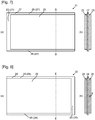
- Fig. 7(a) is a schematic plan view illustrating a positive electrode included in the non-aqueous electrolyte secondary battery according to the present embodiment
- Fig. 7(b) is a schematic sectional view illustrating the positive electrode taken along a dotted line D - D in Fig. 7(a).
- Fig. 8(a) is a schematic plan view illustrating a negative electrode included in the non-aqueous electrolyte secondary battery according to the present embodiment
- Fig. 8(b) is a schematic sectional view illustrating the negative electrode taken along a dotted line E - E in Fig. 8(a) .
- Fig. 9 is a schematic sectional view illustrating a negative-electrode active material layer in a range F enclosed by a dotted line in Fig. 8 .
- a non-aqueous electrolyte secondary battery 20 includes an electrode body 12 having a structure in which a positive electrode 21 including a positive-electrode active material and a negative electrode 22 including a negative-electrode active material 33 are stacked with a separator 24 interposed therebetween; a non-aqueous electrolyte solution 5 containing a flame retardant; and an outer casing 17 accommodating the electrode body 12 and the non-aqueous electrolyte solution 5, wherein the non-aqueous electrolyte solution 5 in the electrode body 12 has a flame retardant concentration lower than a flame retardant concentration of the non-aqueous electrolyte solution 5 between the electrode body 12 and the outer casing 17.
- non-aqueous electrolyte secondary battery 20 of the present embodiment will be described.
- the outer casing 17 may be made of a hard material or a soft material.
- a material that can popularly be used for a non-aqueous electrolyte secondary battery can be used for the non-aqueous electrolyte secondary battery of the present invention.
- the material of the outer casing is not particularly limited, so long as it is not so greatly deformed even if the electrode body 12, a positive-electrode current collector 3, a negative-electrode current collector 4, and a non-aqueous electrolyte solution 5 are accommodated therein.
- the material of the outer casing 17 include a metal material such as aluminum, aluminum alloy, iron, iron alloy, or stainless, a material formed by plating nickel, tin, chromium, or zinc to the metal material, or a rigid plastic.
- the material of the outer casing is not particularly limited, so long as the electrode body 12, the positive-electrode current collector 3, the negative-electrode current collector 4, and the non-aqueous electrolyte solution 5, which are accommodated therein, do not leak therefrom.
- a laminate pouch can be used.
- the outer casing 17 has a battery case 1 for accommodating the electrode body 12.
- the outer casing 17 may also have a lid member 2.
- the battery case 1 can accommodate the electrode body 12, the positive-electrode current collector 3, the negative-electrode current collector 4, and the non-aqueous electrolyte solution 5 therein.
- the battery case 1 can also be bonded to the lid member 2.
- the shape of the battery case 1 may be rectangle, cylindrical, a thin shape, or a coin shape.
- the battery case 1 has an opening into which the electrode body 12 is inserted into the battery case 1. This opening is closed by the lid member 2. Thus, the electrode body 12 can be accommodated into the battery case 1.
- the lid member 2 closes the opening formed on the battery case 1 for inserting the electrode body 12.
- the battery case 1 and the lid member 2 are bonded by a laser welding, resistance welding, ultrasonic welding, or caulking, or by use of an adhesive agent, to seal the battery case 1.
- the positive-electrode current collector 3 and the negative-electrode current collector 4 can be fixed to the lid member 2.
- the electrode body 12 can be connected to the positive-electrode current collector 3 and the negative-electrode current collector 4. With this, the lid member 2, the positive-electrode current collector 3, the negative-electrode current collector 4, and the electrode body 12 can be formed integral.
- the positive-electrode current collector 3, the negative-electrode current collector 4, and the electrode body 12, which are integrated, are put into the battery case 1, and the opening of the battery case 1 is closed by the lid member 2.
- the electrode body 12 connected to the positive-electrode current collector 3 and the negative-electrode current collector 4 can be accommodated into the outer casing 17.
- the non-aqueous electrolyte solution 5 can be injected into the outer casing 17 after the opening of the battery case 1 is closed by the lid member 2.
- the non-aqueous electrolyte solution 5 is accommodated into the outer casing 17 together with the electrode body 12.
- the electrode body 12 is dipped in the non-aqueous electrolyte solution 5, so that a positive-electrode active material layer 25 and a negative-electrode active material layer 26 included in the electrode body 12 contain the non-aqueous electrolyte solution 5.
- the non-aqueous electrolyte solution 5 contains supporting electrolyte salts containing ions that move charges, such as lithium ions or sodium ions, as a solute. Therefore, charges can be moved between the positive-electrode active material and the negative-electrode active material via the non-aqueous electrolyte solution, and hence, the non-aqueous electrolyte secondary battery 20 can be charged and discharged.
- At least a part of the non-aqueous electrolyte solution 5 in the outer casing 17 contains a flame retardant as a solute. With this, a flash point of the non-aqueous electrolyte solution 5 can be raised, and therefore, safety of the non-aqueous electrolyte secondary battery 20 can be enhanced.
- the non-aqueous electrolyte solution 5 can contain ethylene carbonate.
- a component of the non-aqueous electrolyte solution might be consumed by an electrochemical reaction (for example, a formation reaction of an SEI) in the electrode active materials, and so, a flame retardant contained in the non-aqueous electrolyte solution might be consumed by the electrochemical reaction in the electrode active materials.
- an electrochemical reaction for example, a formation reaction of an SEI
- a flame retardant contained in the non-aqueous electrolyte solution might be consumed by the electrochemical reaction in the electrode active materials.
- the amount of the flame retardant to be consumed can be reduced by setting the flame retardant concentration in the non-aqueous electrolyte solution around the electrode active material to be lower than the other portions.
- the flame retardant concentration in the non-aqueous electrolyte solution 5 in the electrode body 12 is lower than the flame retardant concentration in the non-aqueous electrolyte solution 5 between the electrode body 12 and the outer casing 17.
- the flame retardant in the non-aqueous electrolyte solution supplied to the positive-electrode active material layer or the negative-electrode active material layer is reduced. This prevents the consumption of the flame retardant due to an electrochemical reaction in the electrode active material. Therefore, the reduction in the flame retardant concentration in the non-aqueous electrolyte solution 5 can be prevented.
- the flame retardant concentration in the non-aqueous electrolyte solution 5 can be measured by extracting and analyzing the non-aqueous electrolyte solution 5 in the electrode body 12 and the non-aqueous electrolyte solution 5 between the outer casing 17 and the electrode body 12 after the battery is disassembled.
- the non-aqueous electrolyte solution in the electrode body 12 means here a non-aqueous electrolyte solution retained in the electrode body 12, i.e., a non-aqueous electrolyte solution in pores of the electrode active material layer, a non-aqueous electrolyte solution in a gap between an electrode and a separator, and a non-aqueous electrolyte solution inside a fixing member such as a shrink tube 15 holding electrodes together.
- the non-aqueous electrolyte solution between the electrode body and the outer casing means a non-aqueous electrolyte solution between the outermost separator that fixes the electrode body all together and the outer casing 17.
- a fixing member such as the shrink tube 15, for fixing the electrode body 12
- the non-aqueous electrolyte solution between the electrode body and the outer casing means a non-aqueous electrolyte solution between the fixing member and the outer casing 17.
- the present embodiment describes, as one example, a structure in which the positive electrode 12 and the negative electrode 22 are stacked, and the separator 24 is disposed between the positive electrode 21 and the negative electrode 22.
- the present embodiment is applicable to a battery having other structures, for example, a battery whose electrode body 12 has a wound structure.
- the inside of the opening is not considered as the inside of the electrode body 12.
- a non-aqueous electrolyte solution in this opening is not included in the non-aqueous electrolyte solution in the electrode body, but corresponds to the non-aqueous electrolyte solution between the electrode body and the outer casing.
- the non-aqueous electrolyte solution 5 in the pores of the positive-electrode active material layer 25 or the negative-electrode active material layer 26 may have a lower flame retardant concentration than that in the non-aqueous electrolyte solution 5 between the electrode body 12 and the outer casing 17. This prevents the consumption of the flame retardant due to an electrochemical reaction in the electrode active material. Therefore, the reduction in the flame retardant concentration in the non-aqueous electrolyte solution 5 can be prevented.
- the flame retardant concentration in the non-aqueous electrolyte solution 5 in the pores of the positive-electrode active material layer 25 or the negative-electrode active material layer 26 can be measured with a process in which the battery is disassembled to extract the positive electrode 21 or the negative electrode 22, and then, the non-aqueous electrolyte solution is extracted from the positive electrode 21 or the negative electrode 22 with a centrifuge or the like to analyze the flame retardant concentration.
- Examples of a method of allowing the flame retardant concentration in the non-aqueous electrolyte solution 5 in the electrode body 12 to be lower than the flame retardant concentration in the non-aqueous electrolyte solution 5 between the electrode body 12 and the outer casing 17 include a method of dipping the electrode body 12 into a non-aqueous electrolyte solution 5a containing a flame retardant after a non-aqueous electrolyte solution 5b free of a flame retardant is retained in the electrode body 12.
- the non-aqueous electrolyte solution can use carbonates, lactones, ethers, esters, etc. as a solvent. Two or more kinds of these solvents can be used as a mixture. Among these, especially a solvent prepared by mixing cyclic carbonate such as ethylene carbonate (EC) or propylene carbonate (PC) and chain carbonate such as diethyl carbonate (DEC) or dimethyl carbonate (DMC) is preferable.
- EC ethylene carbonate
- PC propylene carbonate
- DEC diethyl carbonate
- DMC dimethyl carbonate
- the non-aqueous electrolyte solution is prepared by dissolving a lithium salt serving as a supporting electrolyte salt, such as LiCF3SO3, LiAsF6, LiClO4, LiBF4, LiPF6, LiBOB, LiN(CF3SO2)2, or LiN(C2F5SO2), or a sodium salt solute such as NaClO4, NaPF6, NaAsF6, NaSbF6, NaBF4, NaCF3SO3, NaN(SO2CF3)2, a sodium salt of lower aliphatic carboxylic acid, or NaAlCl4 in a solvent.
- a lithium salt serving as a supporting electrolyte salt such as LiCF3SO3, LiAsF6, LiClO4, LiBF4, LiPF6, LiBOB, LiN(CF3SO2)2, or LiN(C2F5SO2)
- a sodium salt solute such as NaClO4, NaPF6, NaAsF6, NaSbF6, NaBF4, NaCF3SO3, NaN(SO2CF3)2,
- Examples of the flame retardant contained in the non-aqueous electrolyte solution include a phosphazene compound or a phosphoric ester compound.
- Examples of the phosphoric ester include triethyl phosphate, tripropyl phosphate, tributyl phosphate, triphenyl phosphate, tritolyl phosphate, and tris(trifluoroethyl) phosphate.
- Examples of the phosphazene compound include a cyclic phosphazene derivative represented by (NPR2)n substituted with a substituent R (wherein, n is 3 to 15, and examples of R include a halogen group such as fluorine, an alkoxy group such as an ethoxy group, propoxy group, or methoxy ethoxy methyl group, an alkoxy-substituted alkoxy group, or an aryl group such as a phenoxy group.
- NPR2n cyclic phosphazene derivative represented by (NPR2)n substituted with a substituent R
- R include a halogen group such as fluorine, an alkoxy group such as an ethoxy group, propoxy group, or methoxy ethoxy methyl group, an alkoxy-substituted alkoxy group, or an aryl group such as a phenoxy group.
- hydrogen in the above substituent or a side chain group can be substituted with a halogen element such as fluorine.) which has a chain bind of phosphoric acid and nitrogen as a basic structure, and has a side chain group R added to phosphor.
- a cyclic phosphazene derivative is preferable, and especially a derivative in which R is an alkoxy group and fluorine is preferable.
- the non-aqueous electrolyte solution used for forming an SEI on the surface of the negative-electrode active material 33 does not contain a flame retardant.
- An additive agent such as VC (vinylene carbonate), PS (propane sultone), VEC (vinyl ethyl carbonate), or PRS (propene sultone) may be mixed singly in the non-aqueous electrolyte solution, or two or more kinds of these additive agents may be mixed, according to need.
- VC vinyllene carbonate
- PS propane sultone
- VEC vinyl ethyl carbonate
- PRS propene sultone
- the electrode body 12 causes a battery reaction with the non-aqueous electrolyte solution 5 filled in the outer casing 17. Due to this battery reaction, the non-aqueous electrolyte secondary battery 20 can be discharged and charged.
- the electrode body 12 includes the separator 24, and the positive electrodes 21 and the negative electrodes 22 disposed via the separator 24. As illustrated in Fig. 6 , the electrode body 12 can be configured to include the separator 24 folded in zigzag, and the positive electrodes 21 and the negative electrodes 22, wherein the positive electrodes 21 and the negative electrodes 22 are disposed in valley folds of the separator 24, and each of the positive electrodes 21 and each of the negative electrodes 22 are disposed alternately with the separator 24 interposed therebetween. An end of the separator 24 may wrap a stacked body of the positive electrodes 21 and the negative electrodes 22 to completely cover the electrode body 12, and may be fixed with a tape.
- the above structure is illustrated.
- a wound structure in which the positive electrode 21 and the negative electrode 22 disposed via a generally used separator 24 are winded, and a stacked structure in which the positive electrode 21 and the negative electrode 22 disposed via the individual separator 24 are stacked can be employed.
- the separator 24 has a sheet-like structure, and is disposed between the positive electrode 21 and the negative electrode 22.
- the separator 24 can prevent a short-circuit current from flowing between the positive electrode 21 and the negative electrode 22.
- the separator 24 is not particularly limited, so long as it can transmit ions that move charges.
- a microporous film of polyolefin can be used.
- the positive electrode 21 includes a positive-electrode current collector sheet 27, and a positive-electrode active material layer 25 formed on both surfaces of the positive-electrode current collector sheet 27.
- the positive electrode 21 can be formed as illustrated in Figs. 7(a) and (b) , for example. It can be formed by forming the positive-electrode active material layer 25 on both surfaces of the rectangular positive-electrode current collector sheet 27.
- the positive electrode 21 can be formed to have an electrode connection portion 23 that is connected to the positive-electrode current collector 3. The electrode connection portion 23 in Fig.
- the electrode connection portion 23 can also be formed such that a convex lug portion protruding outwardly from one end of the positive-electrode current collector sheet 27 is formed on this end, and the positive-electrode active material layer 25 is not formed on the lug portion.
- the positive-electrode current collector sheet 27 is not particularly limited, so long as it has an electric conduction property, and has the positive-electrode active material layer 25 formed on its surface.
- a metal foil is used.
- an aluminum foil is used.
- the positive-electrode active material layer 25 can be formed on the positive-electrode current collector sheet 27 by adding a conductive agent or binder to a positive-electrode active material by a known method such as a coating method.
- the positive-electrode active material layer 25 can be formed to have porosity.
- the positive-electrode active material can also be an material that can reversibly extract and insert sodium ions, and examples of such material include an oxide represented by NaM1aO2 such as NaFeO2, NaMnO2, NaNiO2 or NaCoO2, an oxide represented by Na0.44Mn1-aM1aO2, or an oxide represented by Na0.7Mn1-aM1aO2.05
- M1 is one or more kinds of transition metal element, 0 ⁇ a ⁇ 1)
- an oxide represented by NabM2cSi12O30 M2 is one or more kinds of transition metal element, 2 ⁇ b ⁇ 6, 2 ⁇ c ⁇ 5) such as Na6Fe2Si12O30 or Na2Fe5Si12O30
- an oxide represented by NadM3eSi6O18 M3 is one or more kinds of transition metal element, 3 ⁇ d ⁇ 6, 1 ⁇ e ⁇
- the negative electrode 22 includes a negative-electrode current collector sheet 28, and a negative-electrode active material layer 26 formed on both surfaces of the negative-electrode current collector sheet 28.
- the negative electrode 22 can be formed as illustrated in Figs. 8(a) and 8(b) , for example. It can be formed by forming the negative-electrode active material layer 26 on both surfaces of the rectangular negative-electrode current collector sheet 28.
- the negative electrode 22 can be formed to have an electrode connection portion 23 that is connected to the negative-electrode current collector 4. The electrode connection portion 23 in Fig.
- the electrode connection portion 23 can also be formed such that a lug portion similar to the above lug portion for the positive electrode 21 is formed on one end of the negative-electrode current collector sheet 28, and the negative-electrode active material layer 26 is not formed on the lug portion.
- the negative-electrode current collector sheet 28 is not particularly limited, so long as it has an electric conduction property, and has the negative-electrode active material layer 26 formed on its surface.
- a metal foil is used.
- a copper foil is used.
- the negative-electrode active material layer 26 can be formed on the negative-electrode current collector sheet 28 by adding a conductive agent or binder to a negative-electrode active material by a known method such as a coating method.
- the negative-electrode active material layer 26 can be formed to include particulate negative-electrode active materials and have porosity.
- examples of the material for the negative-electrode active material include graphite, partially graphitized carbon, LiTiO4, and Sn alloy. These materials can be used singly, or two or more kinds can be used as a mixture.
- examples of the material for the negative-electrode active material include graphite, partially graphitized carbon, and hard carbon. These materials can be used singly, or two or more kinds can be used as a mixture.
- the negative electrode 22 can include the solid electrolyte interface film 35 on the surface of the negative-electrode active material 33.
- the solid electrolyte interface film 35 is an SEI (Solid Electrolyte Interface), for example.
- the SEI may be formed on the surface of the positive-electrode active material included in the positive electrode 21.
- the SEI formed on the surface of the positive-electrode active material preferably has a portion made of a component derived from a non-aqueous electrolyte solution substantially free of a flame retardant, and further, the SEI is preferably made of a component derived from a non-aqueous electrolyte solution substantially free of a flame retardant.
- the negative electrode in the lithium ion secondary battery according to the present embodiment which is an example of a non-aqueous electrolyte secondary battery, will be described.
- the negative-electrode active material 33 is a graphite particle 32
- the negative-electrode active material layer 26 has porosity
- the non-aqueous electrolyte solution 5 is permeated into the pores in the negative-electrode active material layer 26, and the SEI 35 is formed on the surface of the graphite particle 32, the cross-section of the negative-electrode active material layer 26 is considered to become the one illustrated in Fig. 9 .
- the SEI is formed on the surface of the negative-electrode active material 33 or on the surface of the positive-electrode active material can be confirmed by analyzing the surface of the negative-electrode active material 33 or the surface of the positive-electrode active material with an atom force microscope (AFM), a scanning tunneling microscope (STM), or the like.
- the components of the SEI can be checked with a secondary ion mass spectrometry (SIMS), an X-ray photoelectron spectroscopy (XPS), an Auger electron spectroscopy (AES), or the like.
- covering the surface of the negative-electrode active material 33 or the surface of the positive-electrode active material with the SEI can prevent an excessive reaction between the electrode active material and the electrolyte solution, and therefore, can stabilize the charging and discharging characteristics of the lithium ion secondary battery 20.
- the SEI is formed on the surface of the negative-electrode active material or on the surface of the positive-electrode active material with a decomposition of the electrolyte contained in the non-aqueous electrolyte solution around the surface of the electrode active material or the solvent of the non-aqueous electrolyte solution, or a reaction between the solvent and lithium ions, which are side reactions upon charging the lithium ion secondary battery, especially upon a first charging of the electrode (pre-charging in the embodiment of the present invention). Therefore, the SEI is composed of a component derived from the non-aqueous electrolyte solution around the surface of the electrode active material.
- the SEI formed by using this non-aqueous electrolyte solution as a raw material is considered to include these components or the components generated by the chemical reaction of these components. Accordingly, when the non-aqueous electrolyte solution around the surface of the electrode active material upon the formation of the SEI contains a flame retardant, the SEI is considered to contain the flame retardant or a component generated by the chemical reaction of the flame retardant.
- the SEI When the non-aqueous electrolyte solution around the surface of the electrode active material upon the formation of the SEI does not contain a flame retardant, the SEI is not considered to contain the flame retardant or a component generated by the chemical reaction of the flame retardant. It is considered that the SEI is formed on the surface of the electrode active material mainly upon the first charging of the electrode (pre-charging in the embodiment of the present invention). However, when the lithium ion secondary battery is repeatedly charged and discharged, the SEI is damaged and deteriorated, though little by little. The deteriorated portion of the SEI is newly reproduced with the non-aqueous electrolyte solution around the surface of the electrode active material as a raw material.
- the SEI is composed of the component derived from the non-aqueous electrolyte solution, and it is a polymer in which carbonate-derived structures are linked.
- a structure derived from an impurity such as a flame retardant is inserted therein, it is considered that the structure of the SEI is disordered to deteriorate the quality.
- the electrolyte solution containing a flame retardant it is considered that a structure derived from the flame retardant is inserted into the SEI, and this deteriorates the quality of the SEI and accelerates the deterioration of the SEI.
- the quality of the SEI initially formed is excellent, deterioration is difficult to occur, and impurities are difficult to be inserted during the reproduction, and therefore, more effective result will be produced.
- the SEI forming reaction is carried out in an electrolyte solution containing no flame retardant in order to enhance the quality of the SEI. Especially, since the SEI is formed most often upon the first charging of the electrode, it is more effective to enhance the quality of the SEI formed upon the first charging of the electrode.
- the SEI 35 on the negative-electrode active material 33 included in the negative electrode 22 of the lithium ion secondary battery 20 can be configured to have a portion composed of a component derived from a non-aqueous electrolyte solution 5b substantially free of a flame retardant. Therefore, the concentration of the flame retardant or the concentration of the component produced by the chemical reaction of the flame retardant contained in the SEI 35 becomes lower than that of the SEI formed by using the non-aqueous electrolyte solution containing a flame retardant as a raw material.
- the SEI 35 may be formed to include a portion composed of a component derived from the non-aqueous electrolyte solution 5b substantially free of a flame retardant and to partly include a portion composed of a component derived from the non-aqueous electrolyte solution 5b substantially containing a flame retardant. However, it is preferable that the SEI 35 is made of only the portion composed of a component derived from the non-aqueous electrolyte solution 5b substantially free of a flame retardant.
- Whether or not the SEI 35 has the portion composed of the component derived from the non-aqueous electrolyte solution 5b substantially free of a flame retardant can be checked as follows. Specifically, a component of an SEI on a negative-electrode active material in a lithium ion secondary battery to be tested is checked, and then, the analysis result of this component, an analysis result of a component of an SEI composed of only a component derived from a non-aqueous electrolyte solution free of a flame retardant, and an analysis result of a component of an SEI composed of only a component derived from a non-aqueous electrolyte solution containing a flame retardant are compared.
- a method for producing a non-aqueous electrolyte secondary battery 20 in which a flame retardant concentration in the non-aqueous electrolyte solution in the electrode body 12 is lower than the flame retardant concentration in the non-aqueous electrolyte solution between the electrode body 12 and the outer casing 17 will be described.
- Figs. 10 to 13 are process diagrams of the method for producing the non-aqueous electrolyte secondary battery according to the present embodiment.
- the method for producing the non-aqueous electrolyte secondary battery 20 includes the steps of: impregnating a porous negative-electrode active material layer 26 and a porous positive-electrode active material layer 25 with a non-aqueous electrolyte solution 5b by dipping an electrode body 12, which has a structure in which a negative electrode 22 including the negative-electrode active material layer 26 and a positive electrode 21 including the positive-electrode active material layer 25 are stacked with a separator 24 interposed therebetween, into a non-aqueous electrolyte solution 5b substantially free of a frame retardant; and placing a flame retardant and a non-aqueous electrolyte solution into an outer casing 17 accommodating the positive electrode 21 and the negative electrode 22.
- the step of placing a flame retardant and a non-aqueous electrolyte solution into the outer casing 17 accommodating the positive electrode 21 and the negative electrode 22 can raise the flash point of the non-aqueous electrolyte solution 5 in the outer casing 17, whereby safety of the non-aqueous electrolyte secondary battery can be enhanced.
- the non-aqueous electrolyte solution 5 retained in the electrode body 12 is difficult to move. Therefore, the flame retardant is difficult to be diffused into the non-aqueous electrolyte solution 5 in the electrode body 12, even if the non-aqueous electrolyte solution 5 containing a flame retardant is injected to the outside of the electrode body 12 retaining the non-aqueous electrolyte solution 5.
- the non-aqueous electrolyte solution 5a containing a flame retardant has higher viscosity than the non-aqueous electrolyte solution 5b free of a flame retardant, the flame retardant is difficult to be inserted into the electrode body 12.
- the flame retardant concentration in the non-aqueous electrolyte solution in the electrode body 12 can be set lower than the flame retardant concentration in the non-aqueous electrolyte solution between the electrode body 12 and the outer casing 17. This can suppress the consumption of the flame retardant caused by the electrochemical reaction in the positive-electrode active material or the negative-electrode active material 33 due to the charging and discharging of the produced non-aqueous electrolyte secondary battery 20.
- the reduction in the flame retardant concentration of the non-aqueous electrolyte solution 5 caused by the repeated charging and discharging of the battery can be suppressed, resulting in that a drop of the flash point of the non-aqueous electrolyte solution 5 can be suppressed even if the non-aqueous electrolyte secondary battery 20 is used for a long time.
- the state in which the surface of the positive-electrode active material included in the positive electrode 21 and the surface of the negative-electrode active material 33 included in the negative electrode are in contact with the non-aqueous electrolyte solution 5 substantially free of a flame retardant is formed, whereby the non-aqueous electrolyte solution 5 around the surface of the positive-electrode active material and the non-aqueous electrolyte solution 5 around the surface of the negative-electrode active material 33 can be the non-aqueous electrolyte solution 5 substantially free of a flame retardant.
- a solid electrolyte interface film composed of a component derived from the non-aqueous electrolyte solution 5 substantially free of a flame retardant can be formed on the surface of the positive-electrode active material or the negative-electrode active material 33.
- the electrode body 12 formed by stacking the positive electrode 21 and the negative electrode 22 via the separator 24 is fixed to the lid member 2, and then, this electrode body 12 can be dipped into the non-aqueous electrolyte solution 5b, which is substantially free of a flame retardant and stored in a pretreatment container 37.
- the non-aqueous electrolyte solution 5b stored in the pretreatment container 37 can be permeated into the positive-electrode active material layer 25 and the negative-electrode active material layer 26, and this can form a state in which the surface of the positive-electrode active material and the surface of the negative-electrode active material 33 are brought into contact with the non-aqueous electrolyte solution 5b substantially free of a flame retardant.
- the non-aqueous electrolyte solution 5b is retained in the electrode body 12. As illustrated in the step A in Fig. 10 , a voltage is applied between the positive electrode 21 and the negative electrode 22 with this state to perform pre-charging.
- a solid electrolyte interface film composed of a component derived from the non-aqueous electrolyte solution 5b substantially free of a flame retardant can be formed on the surface of the positive-electrode active material or the negative-electrode active material 33.
- the electrode body 12 removed from the pretreatment container 37 is accommodated into the battery case 1 as illustrated in the step B in Fig. 10 , and then, the non-aqueous electrolyte solution 5a containing a flame retardant is injected into the battery case 1 as illustrated in the step C in Fig. 10 .
- the non-aqueous electrolyte secondary battery can be produced.
- the flame retardant concentration in the non-aqueous electrolyte solution 5 in the electrode body 12 is lower than the flame retardant concentration in the non-aqueous electrolyte solution between the electrode body 12 and the battery case 1.
- the non-aqueous electrolyte solution 5a containing a flame retardant dissolved therein is injected into the battery case 1.
- a flame retardant and the non-aqueous electrolyte solution 5 may be separately injected into the battery case 1, and the flame retardant may be dissolved in the non-aqueous electrolyte solution 5 in the battery case 1.
- Such modification can similarly be applied to a method for producing described later.
- the electrode body 12 formed by stacking the positive electrode 21 and the negative electrode 22 via the separator 24 is fixed to the lid member 2, and then, this electrode body 12 can be dipped into the non-aqueous electrolyte solution 5b, which is free of a flame retardant and stored in the pretreatment container 37.
- the non-aqueous electrolyte solution 5b stored in the pretreatment container 37 can be permeated into the positive-electrode active material layer 25 and the negative-electrode active material layer 26, and this can form a state in which the surface of the positive-electrode active material and the surface of the negative-electrode active material 33 are brought into contact with the non-aqueous electrolyte solution 5b substantially free of a flame retardant.
- the non-aqueous electrolyte solution 5b is retained in the electrode body 12. After the non-aqueous electrolyte solution 5b is retained in the electrode body 12, the electrode body 12 removed from the pretreatment container 37 is accommodated into the battery case 1 as illustrated in the step B in Fig.
- the non-aqueous electrolyte solution 5a containing a flame retardant is injected into the battery case 1 as illustrated in the step C in Fig. 11 .
- the non-aqueous electrolyte secondary battery can be produced.
- the non-aqueous electrolyte solution 5b free of a flame retardant is permeated and retained in the electrode body 12.
- the flame retardant can hardly be permeated into the positive-electrode active material layer 25 and the negative-electrode active material layer 26, and therefore, the surface of the positive-electrode active material and the surface of the negative-electrode active material 33 keep in contact with the non-aqueous electrolyte solution 5 substantially free of a flame retardant. Then, as illustrated in the step D in Fig. 11 , a voltage is applied between the positive electrode 21 and the negative electrode 22 with this state to perform pre-charging.
- a solid electrolyte interface film composed of a component derived from a non-aqueous electrolyte solution substantially free of a flame retardant can be formed on the surface of the positive-electrode active material or the negative-electrode active material.
- the flame retardant concentration in the non-aqueous electrolyte solution 5 in the electrode body 12 becomes lower than the flame retardant concentration in the non-aqueous electrolyte solution between the electrode body 12 and the battery case 1.
- the electrode body 12 produced by stacking the positive electrode 21 and the negative electrode 22 via the separator 24 is fixed to the lid member 2, and the electrode body 12 is stored in the battery case 1.
- the non-aqueous electrolyte solution 5b free of a flame retardant is injected into the battery case 1 to allow the lower part of the electrode body 12 to be dipped in the non-aqueous electrolyte solution 5b.
- the non-aqueous electrolyte solution 5b is permeated into the electrode body 12 due to the capillary action, and this can form the state in which the surface of the positive-electrode active material and the surface of the negative-electrode active material are brought into contact with the non-aqueous electrolyte solution 5b free of a flame retardant.
- the non-aqueous electrolyte solution 5b is retained in the electrode body 12. After the non-aqueous electrolyte solution 5b is permeated into the electrode body 12, the non-aqueous electrolyte solution 5a containing a flame retardant is injected into the battery case 1 as illustrated in the step C in Fig. 12 .
- the non-aqueous electrolyte secondary battery can be produced.
- the non-aqueous electrolyte solution 5a containing a flame retardant is injected into the battery case 1
- the non-aqueous electrolyte solution 5b free of a flame retardant is permeated and retained in the positive-electrode active material layer 25 and the negative-electrode active material layer 26.
- the flame retardant can hardly be permeated into the positive-electrode active material layer 25 and the negative-electrode active material layer 26, and therefore, the surface of the positive-electrode active material and the surface of the negative-electrode active material 33 keep in contact with the non-aqueous electrolyte solution 5 substantially free of a flame retardant. Then, as illustrated in the step D in Fig. 12 , a voltage is applied between the positive electrode 21 and the negative electrode 22 with this state to perform pre-charging.
- a solid electrolyte interface film composed of a component derived from a non-aqueous electrolyte solution substantially free of a flame retardant can be formed on the surface of the positive-electrode active material or the negative-electrode active material 33.
- the flame retardant concentration in the non-aqueous electrolyte solution 5 in the electrode body 12 becomes lower than the flame retardant concentration in the non-aqueous electrolyte solution between the electrode body 12 and the battery case 1.
- a portion of the non-aqueous electrolyte solution 5b in the battery case 1 may be discharged to adjust the amount of the non-aqueous electrolyte solution 5, before the non-aqueous electrolyte solution 5a containing a flame retardant is injected into the battery case 1.
- the electrode body 12 produced by stacking the positive electrode 21 and the negative electrode 22 via the separator 24 is fixed to the lid member 2, and the electrode body 12 is stored in the battery case 1.
- the non-aqueous electrolyte solution 5b free of a flame retardant is injected into the battery case 1 to allow substantially the whole electrode body 12 to be dipped in the non-aqueous electrolyte solution 5b.
- the non-aqueous electrolyte solution 5b is permeated into the positive-electrode active material layer 25 and the negative-electrode active material layer 26, and this can form the state in which the surface of the positive-electrode active material and the surface of the negative-electrode active material 33 are brought into contact with the non-aqueous electrolyte solution 5b free of a flame retardant.
- the non-aqueous electrolyte solution 5b is retained in the electrode body 12. Then, as illustrated in the step C in Fig. 13 , a voltage is applied between the positive electrode 21 and the negative electrode 22 with this state to perform pre-charging.
- a solid electrolyte interface film composed of a component derived from a non-aqueous electrolyte solution free of a flame retardant can be formed on the surface of the positive-electrode active material or the negative-electrode active material 33.
- the non-aqueous electrolyte solution 5b in the battery case 1 is discharged as illustrated in the step D in Fig. 13 , and then, the non-aqueous electrolyte solution 5a containing a flame retardant is injected into the battery case 1 as illustrated in the step E in Fig. 13 .
- the non-aqueous electrolyte secondary battery can be produced.
- the flame retardant concentration in the non-aqueous electrolyte solution 5 in the electrode body 12 becomes lower than the flame retardant concentration in the non-aqueous electrolyte solution between the electrode body 12 and the battery case 1.
- the flame retardant concentration in the non-aqueous electrolyte solution 5 in the electrode body 12 is lower than the flame retardant concentration in the non-aqueous electrolyte solution between the electrode body 12 and the battery case 1.
- the consumed amount of the flame retardant due to the electrochemical reaction in the electrode active materials can be reduced, and therefore, the situation in which the flash point of the non-aqueous electrolyte solution 5 is lowered due to the reduction in the flame retardant concentration in the non-aqueous electrolyte solution 5 can be prevented.
- the solid electrolyte interface film composed of a component derived from the non-aqueous electrolyte solution substantially free of a flame retardant is formed upon pre-charging.
- the solid electrolyte interface film can be formed to have excellent quality. This can prevent the deterioration in the quality of the solid electrolyte interface film and the acceleration in the deterioration of the solid electrolyte interface film, which are caused because the component derived from the flame retardant is inserted into the solid electrolyte interface film. Accordingly, the reduction in the battery capacity can be suppressed, even if the non-aqueous electrolyte secondary battery is used to be repeatedly charged and discharged.
- the non-aqueous electrolyte solution 5 in the battery case 1 contains a flame retardant, a flash point of the non-aqueous electrolyte solution 5 is high, whereby safety of the non-aqueous electrolyte secondary battery is high.
- high quality of the solid electrolyte interface film can suppress consumption of the flame retardant in the non-aqueous electrolyte solution. Accordingly, the reduction in the concentration of the flame retardant in the non-aqueous electrolyte solution caused by the repeated charging and discharging can be suppressed. With this, safety of the non-aqueous electrolyte secondary battery can further be enhanced.
- a part of the solid electrolyte interface film formed upon pre-charging is considered to be damaged, because the shape of the negative-electrode active material 33 is changed with the charging and discharging of the non-aqueous electrolyte secondary battery.
- the solid electrolyte interface film is considered to be newly formed on this damaged portion from the non-aqueous electrolyte solution 5 upon the subsequent charging.
- the newly formed solid electrolyte interface film might be composed of a component derived from the non-aqueous electrolyte solution containing a flame retardant. However, it is considered that most of the solid electrolyte interface film formed upon pre-charging remains on the surface of the negative-electrode active material.
- examples of a method for producing a lithium ion non-aqueous electrolyte secondary battery 20 in which a flame retardant concentration in the non-aqueous electrolyte solution in the electrode body 12 is lower than a flame retardant concentration in the non-aqueous electrolyte solution between the electrode body 12 and the outer casing 17 include a method in which a flame retardant is applied onto an inner face of the outer casing, an electrolyte solution free of a flame retardant is injected after a battery is assembled, and a difference in concentration is generated by slowly dissolving the flame retardant into the electrolyte solution; and a method in which a flame retardant is encapsulated into a sustained release capsule, the resultant is mixed into an electrolyte solution, and a difference in concentration is generated by slowly dissolving the flame retardant into the electrolyte solution. It is obvious that the effect similar to the effect of the present invention can be obtained by producing a non-aqueous electrolyte secondary battery with these methods
- the positive-electrode current collector 3 is a member electrically connecting the positive electrode 21 included in the electrode body 12 to an external connection terminal 8a.
- the negative-electrode current collector 4 is a member electrically connecting the negative electrode 22 included in the electrode body 12 to an external connection terminal 8b.
- the current collector 7 (the positive-electrode current collector 3 or the negative-electrode current collector 4) has a plate-like base portion fixed to the outer casing 17 and a plate-like leg portion extending from the base portion.
- the current collector 7 can also be configured to include a projection portion 31 projecting from the base portion and penetrating through the opening formed on the lid member 2.
- the materials of the positive-electrode current collector 3 and the negative-electrode current collector 4 are not particularly limited.
- the positive-electrode current collector 3 can be made of aluminum, and the negative-electrode current collector 4 can be made of copper.
- a method for producing the positive-electrode current collector 3 and the negative-electrode current collector 4 is not particularly limited. For example, they can be produced by press working of a metal plate. A metal plate having a thickness of 1.5 mm or more and 2.5 mm or less can be used for the metal plate.
- the base portion of the positive-electrode current collector 3 and the base portion of the negative-electrode current collector 4 can be fixed to the lid member 2.
- the method of fixing the base portion of the current collector is not particularly limited, so long as the base portion can be fixed such that the positive-electrode current collector 3 or the negative-electrode current collector 4 can be connected to an external wiring.
- the base portion can be fixed as illustrated in the sectional view of Fig. 3 .
- the projection portion 31 of the current collector 7 is inserted into the opening of the lid member 2 and the opening of the external connection terminal 8, and the projection portion 31 is caulked to form the current collector 7, the lid member 2, and the external connection terminal 8 integral with one another.
- the current collector 7 can be fixed to the lid member 2 with the current collector 7 being electrically connected to the external connection terminal 8.
- the non-aqueous electrolyte secondary battery 20 can be charged and discharged via the external connection terminals 8a and 8b.
- an internal insulating member 11 is provided between the inside of the lid member 2 and the current collector 7, while an external insulating member 10 is provided between the outside of the lid member 2 and the external connection terminal 8.
- a packing 13 is provided between the opening of the lid member 2 and the projection portion 31.
- the internal insulating member 11, the external insulating member 10, and the packing 13 are formed integral with the current collector 7, the lid member 2, and the external connection terminal 8.
- the leg portion of the current collector 7 has a shape in which the end of the base portion extends to project from the base portion.
- the leg portion may have a rod-like shape or a plate-like shape.
- the leg portion may be formed simultaneous with the current collector 7 by processing a single metal plate, or may be formed by bonding another metal plate to the base portion.
- leg portion is formed to one base portion.
- leg portion may be branched.
- the leg portion has a connection portion to which the electrode (positive electrode 21 or the negative electrode 22) is connected and a curved portion formed between the base portion and the connection portion.
- the electrode connection portion 23 of the positive electrode 21 is connected to the connection portion of the positive-electrode current collector 3, while the electrode connection portion 23 of the negative electrode 22 is connected to the connection portion of the negative-electrode current collector 4. Due to the connection portion of the current collector, the contact area between the positive-electrode current collector 3 and the positive electrode 21 or between the negative-electrode current collector 4 and the negative electrode 22 can be increased, whereby a conductive resistance can be reduced.
- connection portion is formed enables the connection with the current collector 7 without bending the electrode plate of the electrode body 12, and this can prevent excessive force from being applied to the electrode body 12.
- the method of bonding the electrode connection portion 23 to the connection portion includes ultrasonic welding, spot welding, and laser welding, for example.
- a plurality of electrode connection portions 23 of the positive electrodes 21 can be connected to the connection portion of the positive-electrode current collector 3, and a plurality of electrode connection portions 23 of the negative electrodes 22 can be connected to the connection portion of the negative-electrode current collector 4. In this case, a plurality of electrode connection portions 23 can be connected to the electrode connection portion 23 of the current collector 7 as superimposed.
- the non-aqueous electrolyte secondary battery 20 of the invention is provided with the shrink tube 15 that bundles the electrode body 12, the positive-electrode current collector 3, and the negative-electrode current collector 4 together.
- the shrink tube 15 is made of a tube-shaped resin film, and bundles the electrode body 12, the positive-electrode current collector 3, and the negative-electrode current collector 4 together by thermal shrinkage.
- the shrink tube 15 also covers the electrode body 12, the positive-electrode current collector 3, and the negative-electrode current collector 4.
- the shrink tube 15 may have a heat-sealed seam joint or may be a seamless tube having no seam joint.
- the shrink tube 15 is capable of suppressing bulges or displacement of the electrode body 12 and of preventing the positive electrodes 21 and the negative electrodes 22 in the electrode body 12 to be separated from each other.
- the shrink tube 15 functions as a component for fixing the positive electrodes 21 and the negative electrodes 22 or as a member for maintaining a shape of the electrode body 12.
- a material for the film constituting the shrink tube 15 is a thermally shrinkable resin such as polyethylene, polypropylene, polyolefin, polyvinyl chloride (PVC), polyethylene terephthalate (PET), or a fluorinated resin (such as FEP or PTFE).
- the thermally shrunken tube 15 is capable of increasing closeness of the encompassed positive-electrode current collector 3, negative-electrode current collector 4, and electrode body 12 by bundling the positive-electrode current collector 3, the negative-electrode current collector 4, and the electrode body 12 together, with the result that the thermally shrunken tube is capable of suppressing effects on junctions between the electrode body 12 and the current collectors caused by vibrations applied to the lithium ion battery.
- the film constituting the shrink tube 15 may be 30 ⁇ m or more to 200 ⁇ m or less in thickness.
- the electrode body 12 illustrated in Fig. 6 was assembled by using the positive electrodes 21 using lithium iron phosphate as a positive-electrode active material, the negative electrodes 22 using graphite as a negative-electrode active material, and the separator 24.
- the separator 24 was folded in zigzag.
- the positive electrode 21 and the negative electrode 22 were disposed in valley folds of the separator 24, and each of the positive electrodes 21 and each of the negative electrodes 22 were disposed alternately with the separator interposed therebetween.
- the separator 24 was disposed to completely cover the electrode active material layers, and taped at its end.
- the ends of the positive electrodes 21 were simultaneously welded to the positive-electrode current collector 3 fixed to the lid member 2, and the ends of the negative electrodes 22 were simultaneously welded to the negative-electrode current collector 4 fixed to the lid member 2.
- the electrode body 12, the positive-electrode current collector 3, and the negative-electrode current collector 4 were fixed with the shrink tube 15.
- the electrode body 12 and the non-aqueous electrolyte solution 5 were placed in the battery case 1.
- the lithium ion secondary battery illustrated in Figs. 1 to 5 was produced.
- the battery A as an example 1 was pre-charged in the state in which the electrode body 12 already fixed with the shrink tube 15 was placed into the non-aqueous electrolyte solution 5b, which was stored in the pretreatment container 37 and did not contain a flame retardant, to allow the electrode body 12 to retain the non-aqueous electrolyte solution 5b.
- the pre-charging was conducted for 30 minutes at room temperature and 0.4 C.
- the flame retardant concentration in the non-aqueous electrolyte solution in the electrode body 12 is lower than the flame retardant concentration in the non-aqueous electrolyte solution between the electrode body 12 and the battery case 1.
- pre-charging was performed with the state in which the non-aqueous electrolyte solution 5b free of a flame retardant was brought into contact with the surface of the positive-electrode active material and the surface of the negative-electrode active material. Therefore, it is considered that a solid electrolyte interface film free of a component derived from a flame retardant is formed on the surface of the positive-electrode active material or the negative-electrode active material.
- the flame retardant concentration in the non-aqueous electrolyte solution in the electrode body 12 is lower than the flame retardant concentration in the non-aqueous electrolyte solution between the electrode body 12 and the battery case 1.
- pre-charging was performed with the state in which the non-aqueous electrolyte solution substantially free of a flame retardant was brought into contact with the surface of the positive-electrode active material and the surface of the negative-electrode active material. Therefore, it is considered that a solid electrolyte interface film substantially free of a component derived from a flame retardant is formed on the surface of the positive-electrode active material or the negative-electrode active material.
- the flame retardant concentration in the non-aqueous electrolyte solution in the electrode body 12 is the same as the flame retardant concentration in the non-aqueous electrolyte solution between the electrode body 12 and the battery case 1.
- pre-charging was performed with the state in which the non-aqueous electrolyte solution 5a containing a flame retardant was brought into contact with the surface of the positive-electrode active material and the surface of the negative-electrode active material in the battery C. Therefore, it is considered that a solid electrolyte interface film containing a component derived from a flame retardant is formed on the surface of the positive-electrode active material or the negative-electrode active material.
- neither the non-aqueous electrolyte solution in the electrode body 12 nor the non-aqueous electrolyte solution between the electrode body 12 and the battery case 1 contain a flame retardant.
- the pre-charging was performed to the battery D with the state in which the non-aqueous electrolyte solution free of a flame retardant was in contact with the surface of the positive-electrode active material and the surface of the negative-electrode active material. Therefore, it is considered that a solid electrolyte interface film substantially free of a component derived from a flame retardant is formed on the surface of the positive-electrode active material or the negative-electrode active material.
- the whole non-aqueous electrolyte solution 5 in the battery case 1 does not contain a flame retardant, so that a flash point of the non-aqueous electrolyte solution 5 is considered to be low.
- a charging-discharging test was performed to the produced batteries A to D.
- the temperature of each battery was held at 50°C, and with this state, the battery was charged to 3.50 V with a current value of 1 CA. After reaching 3.50 V, the battery was held with this voltage for 90 minutes. Thereafter, about a ten-minute interval was formed, and then, the battery was discharged to 2.0 V with a current value of 1 CA. After the battery reached 2.0 V, about a ten-minute interval was formed, and then, the battery was again charged to 3.50 V with a constant current with a current value of 1 CA. 300 cycles of the charging-discharging test described above were performed for each of the batteries A to D, and the battery capacity was measured.
- Fig. 14 illustrates the measurement result of the charging-discharging cycle test.
- the battery capacity is shown as a capacity retention rate (%) with the battery capacity in the first charging-discharging cycle being defined as 100%.
- the measurement result of the battery C according to the comparative example 1 in Fig. 14 shows that the capacity retention rate was gradually reduced with the repeated charging-discharging cycles, and the battery capacity after 300 cycles was lower than the battery capacity in the first charging-discharging cycle by about 12.5%. It is considered that the reduction in the capacity retention rate was large because the solid electrolyte interface film containing a component derived from a flame retardant was formed on the surface of the positive-electrode active material or the negative-electrode active material in the battery C.
- the capacity retention rate was gradually reduced with the repeated charging-discharging cycles, and the battery capacity after 300 cycles was lower than the battery capacity in the first charging-discharging cycle by about 9%. It is considered that the reduction in the capacity retention rate was suppressed because the solid electrolyte interface film free of a component derived from a flame retardant was formed on the surface of the positive-electrode active material or the negative-electrode active material in the battery D. Notably, the non-aqueous electrolyte solution in the battery D does not contain a flame retardant.
- the measurement result of the battery A according to the example 1 in Fig. 14 shows that the capacity retention rate was gradually reduced with the repeated charging-discharging cycles, and the battery capacity after 300 cycles was lower than the battery capacity in the first charging-discharging cycle by about 9%. It is considered that the reduction in the capacity retention rate was suppressed because the solid electrolyte interface film substantially free of a component derived from a flame retardant was formed on the surface of the positive-electrode active material or the negative-electrode active material by the pre-charging in the battery A. Although the non-aqueous electrolyte solution in the battery A contains a flame retardant, the battery A has cycle characteristics equal to the battery D.
- the measurement result of the battery B according to the example 2 in Fig. 14 shows that the capacity retention rate was gradually reduced with the repeated charging-discharging cycles, and the battery capacity after 300 cycles was lower than the battery capacity in the first charging-discharging cycle by about 9.5%. It is considered that the reduction in the capacity retention rate was suppressed because the solid electrolyte interface film substantially free of a component derived from a flame retardant was formed on the surface of the positive-electrode active material or the negative-electrode active material by the pre-charging in the battery B. Although the non-aqueous electrolyte solution in the battery B contains a flame retardant, the battery B has cycle characteristics equal to the battery D.
- the flash point of the non-aqueous electrolyte solution extracted from each of the batteries A to D before the charging-discharging cycle test and the flash point of the non-aqueous electrolyte solution extracted from each of the batteries A to D after the charging-discharging cycle test were measured.
- the flash point was measured with Cleveland open cup method.
- the Cleveland open cup method is prescribed in JIS K 2265-4. With this method, a sample is heated under a prescribed condition, and a small flame is put close to the sample. The lowest sample temperature at which the small flame causes the generated vapor to ignite is measured. In this way, a flash point can be obtained.
- Table 1 illustrates the measurement results.
- the flash point after the test was 72°C which was lower than the flash point before the test by about 20°C.
- the conceivable reason is such that the flame retardant concentration in the non-aqueous electrolyte solution is reduced due to the consumption of the flame retardant in the non-aqueous electrolyte solution by the charging-discharging cycle.
- the flash point was 35°C before and after the test. This is considered to be the same as the flash point of the non-aqueous electrolyte solution free of a flame retardant.
- the flash point after the test was 96°C which was higher than the flash point before the test by about 4°C.
- the conceivable reason is such that the consumption of the flame retardant due to electrochemical reaction in the electrode active materials is suppressed due to low flame retardant concentration in the electrode body 12, and the flame retardant concentration in the non-aqueous electrolyte solution is raised due to the consumption of the solvent contained in the non-aqueous electrolyte solution by the charging-discharging cycle.
- Another conceivable reason is such that the consumption of the flame retardant in the non-aqueous electrolyte solution is suppressed due to a high quality of the solid electrolyte interface film formed on the surface of the positive-electrode active material or the negative-electrode active material, and the flame retardant concentration in the non-aqueous electrolyte solution is raised due to the consumption of the solvent contained in the non-aqueous electrolyte solution by the charging-discharging cycle.
- the flash point after the test was 95°C which was higher than the flash point before the test by about 3°C.
- the conceivable reason is such that the consumption of the flame retardant due to electrochemical reaction in the electrode active materials is suppressed due to low flame retardant concentration in the electrode body 12, and the flame retardant concentration in the non-aqueous electrolyte solution is raised due to the consumption of the solvent contained in the non-aqueous electrolyte solution by the charging-discharging cycle.
Landscapes
- Chemical & Material Sciences (AREA)
- Engineering & Computer Science (AREA)
- Chemical Kinetics & Catalysis (AREA)
- Electrochemistry (AREA)
- General Chemical & Material Sciences (AREA)
- Manufacturing & Machinery (AREA)
- Materials Engineering (AREA)
- General Physics & Mathematics (AREA)
- Inorganic Chemistry (AREA)
- Condensed Matter Physics & Semiconductors (AREA)
- Physics & Mathematics (AREA)
- Secondary Cells (AREA)
- Battery Electrode And Active Subsutance (AREA)
Claims (9)
- Sekundärbatterie mit nicht wässrigem Elektrolyten (20), umfassend:- einen Elektrodenkörper (12), der eine Struktur aufweist, in der eine positive Elektrode einschließlich eines positiven aktiven Elektrodenmaterials und eine negative Elektrode einschließlich eines negativen aktiven Elektrodenmaterials mit einem dazwischen eingefügten Separator gestapelt sind;- ein Schrumpfrohr (15), das den Elektrodenkörper (12) bündelt;- eine nicht wässrige Elektrolytlösung, die ein Flammschutzmittel enthält; und- ein äußeres Gehäuse (17), das den Elektrodenkörper (12) und die nicht wässrige Elektrolytlösung aufnimmt, wobei die nicht wässrige Elektrolytlösung im Elektrodenkörper (12) eine Flammschutzmittelkonzentration aufweist, die niedriger ist als eine Flammschutzmittelkonzentration in der nicht wässrigen Elektrolytlösung zwischen dem Schrumpfrohr (15) und dem äußeren Gehäuse (17), und dadurch gekennzeichnet, dass der Elektrodenkörper (12) und das Schrumpfrohr (15) das Flammschutzmittel, das in der nicht wässrigen Elektrolytlösung außerhalb des Schrumpfrohrs (15) enthalten ist, daran hindern, in den Elektrodenkörper (12) geflogen und verbreitet zu werden.
- Sekundärbatterie mit nicht wässrigem Elektrolyten (20) nach Anspruch 1, wobei- die positive Elektrode eine poröse Schicht aus positivem aktivem Elektrodenmaterial umfasst, die das positive aktive Elektrodenmaterial einschließt,- die negative Elektrode eine poröse Schicht aus negativem aktivem Elektrodenmaterial umfasst, die das negative aktive Elektrodenmaterial einschließt, und- die nicht wässrige Elektrolytlösung im Elektrodenkörper (12) die nicht wässrige Elektrolytlösung in Poren der Schicht aus positivem aktivem Elektrodenmaterial oder die nicht wässrige Elektrolytlösung in Poren der Schicht aus negativem aktivem Elektrodenmaterial ist.
- Sekundärbatterie mit nicht wässrigem Elektrolyten (20) nach Anspruch 1 oder 2, wobei die nicht wässrige Elektrolytlösung Ethylencarbonat enthält.
- Sekundärbatterie mit nicht wässrigem Elektrolyten (20) nach einem der Ansprüche 1 bis 3,
wobei das Flammschutzmittel eine Phosphazenverbindung ist. - Sekundärbatterie mit nicht wässrigem Elektrolyten (20) nach einem der Ansprüche 1 bis 4,
wobei das negative aktive Elektrodenmaterial aus einem Graphitmaterial besteht. - Verfahren zum Herstellen einer Sekundärbatterie mit nicht wässrigem Elektrolyten (20), umfassend die folgenden Schritte:- Imprägnieren einer porösen Schicht aus negativem aktivem Elektrodenmaterial und einer porösen Schicht aus positivem aktivem Elektrodenmaterial mit einer nicht wässrigen Elektrolytlösung durch Eintauchen eines Elektrodenkörpers (12) in die nicht wässrige Elektrolytlösung, die im Wesentlichen frei von einem Flammschutzmittel ist, wobei der Elektrodenkörper (12) eine Struktur aufweist, in der eine negative Elektrode einschließlich der porösen Schicht aus negativem aktivem Elektrodenmaterial und eine positive Elektrode einschließlich der porösen Schicht aus positivem aktivem Elektrodenmaterial mit einem dazwischen eingefügten Separator gestapelt sind, wobei der Elektrodenkörper (12) durch ein Schrumpfrohr (15) gebündelt ist; und- Platzieren eines Flammschutzmittels und einer nicht wässrigen Elektrolytlösung in ein äußeres Gehäuse (17), das die positive Elektrode und die negative Elektrode aufnimmt, dadurch gekennzeichnet, dass der Elektrodenkörper (12) und das Schrumpfrohr (15) das Flammschutzmittel, das in der nicht wässrigen Elektrolytlösung außerhalb des Schrumpfrohrs (15) enthalten ist, daran hindern, in den Elektrodenkörper (12) geflogen und verbreitet zu werden.
- Verfahren zum Herstellen der Sekundärbatterie mit nicht wässrigem Elektrolyten (20) nach Anspruch 6, weiter umfassend einen Schritt eines Ladens des Elektrodenkörpers (12) durch Anlegen einer Spannung zwischen der positiven Elektrode und der negativen Elektrode mit dem Zustand, in dem der Elektrodenkörper (12) in die nicht wässrige Elektrolytlösung eingetaucht wird, die im Wesentlichen frei von einem Flammschutzmittel ist.
- Verfahren zum Herstellen der Sekundärbatterie mit nicht wässrigem Elektrolyten (20) nach Anspruch 6 oder 7, wobei der Schritt des Imprägnierens ein Schritt des Imprägnierens des Elektrodenkörpers (12) mit der nicht wässrigen Elektrolytlösung im äußeren Gehäuse (17) ist.
- Verfahren zum Herstellen der Sekundärbatterie mit nicht wässrigem Elektrolyten (20) nach Anspruch 6 oder 7, wobei der Schritt des Imprägnierens ein Schritt des Imprägnierens des Elektrodenkörpers (12) mit der nicht wässrigen Elektrolytlösung in einem anderen Behälter als dem äußeren Gehäuse (17) ist.
Applications Claiming Priority (1)
| Application Number | Priority Date | Filing Date | Title |
|---|---|---|---|
| PCT/JP2012/082401 WO2014091606A1 (ja) | 2012-12-13 | 2012-12-13 | 非水電解液二次電池及び非水電解液二次電池の製造方法 |
Publications (3)
| Publication Number | Publication Date |
|---|---|
| EP2933868A1 EP2933868A1 (de) | 2015-10-21 |
| EP2933868A4 EP2933868A4 (de) | 2016-12-21 |
| EP2933868B1 true EP2933868B1 (de) | 2019-04-10 |
Family
ID=50933925
Family Applications (1)
| Application Number | Title | Priority Date | Filing Date |
|---|---|---|---|
| EP12890013.1A Active EP2933868B1 (de) | 2012-12-13 | 2012-12-13 | Sekundärbatterie mit wasserfreier elektrolytlösung und verfahren zur herstellung einer sekundärbatterie mit wasserfreier elektrolytlösung |
Country Status (6)
| Country | Link |
|---|---|
| US (1) | US10147977B2 (de) |
| EP (1) | EP2933868B1 (de) |
| JP (1) | JP6427744B2 (de) |
| KR (1) | KR101991458B1 (de) |
| CN (1) | CN104854754B (de) |
| WO (1) | WO2014091606A1 (de) |
Families Citing this family (8)
| Publication number | Priority date | Publication date | Assignee | Title |
|---|---|---|---|---|
| EP3353844B1 (de) | 2015-03-27 | 2022-05-11 | Mason K. Harrup | Vollständig anorganische lösungsmittel für elektrolyte |
| US10707531B1 (en) | 2016-09-27 | 2020-07-07 | New Dominion Enterprises Inc. | All-inorganic solvents for electrolytes |
| JP6941796B2 (ja) * | 2016-11-30 | 2021-09-29 | パナソニックIpマネジメント株式会社 | 非水電解質二次電池 |
| KR102366848B1 (ko) | 2019-01-21 | 2022-02-24 | 주식회사 엘지에너지솔루션 | 전극 및 전극 조립체 |
| KR20210022853A (ko) | 2019-08-21 | 2021-03-04 | 의료법인사과나무의료재단 | 치과 진단 시스템 |
| JP7577917B2 (ja) * | 2019-09-20 | 2024-11-06 | 日本電気硝子株式会社 | ナトリウムイオン二次電池及びナトリウムイオン二次電池の製造方法 |
| US12567599B2 (en) | 2021-12-30 | 2026-03-03 | Uchicago Argonne, Llc | Lead acid electrochemical cells with pumped electrolytes and methods of making and using the same |
| US11936004B2 (en) | 2022-01-28 | 2024-03-19 | Uchicago Argonne, Llc | Electrochemical cells and methods of manufacturing thereof |
Family Cites Families (17)
| Publication number | Priority date | Publication date | Assignee | Title |
|---|---|---|---|---|
| JP3055358B2 (ja) | 1992-04-09 | 2000-06-26 | 株式会社ブリヂストン | 非水電解質電池 |
| JPH08148162A (ja) | 1994-11-25 | 1996-06-07 | Fuji Elelctrochem Co Ltd | 角型リチウム電池の製造方法 |
| JP2000311717A (ja) * | 1999-02-25 | 2000-11-07 | Mitsubishi Chemicals Corp | 電池要素及び電池 |
| JP3274102B2 (ja) | 1999-04-05 | 2002-04-15 | 三菱化学株式会社 | リチウム電池用の難燃性電解液 |
| JP2001076759A (ja) * | 1999-08-31 | 2001-03-23 | Sanyo Electronic Components Co Ltd | 電気化学デバイス |
| JP4712152B2 (ja) * | 2000-04-18 | 2011-06-29 | パナソニック株式会社 | 角形電池及びその製造方法 |
| JP2002311717A (ja) * | 2001-04-12 | 2002-10-25 | Ricoh Co Ltd | 画像形成装置 |
| JP2003007332A (ja) | 2001-06-22 | 2003-01-10 | Toyota Motor Corp | リチウム二次電池及びその製造方法 |
| US6797437B2 (en) | 2001-12-28 | 2004-09-28 | Quallion Llc | Electrolyte system and energy storage device using same |
| JP5046352B2 (ja) | 2005-04-06 | 2012-10-10 | 日立マクセルエナジー株式会社 | リチウムイオン二次電池の製造方法 |
| JP2007207455A (ja) | 2006-01-31 | 2007-08-16 | Matsushita Electric Ind Co Ltd | 非水電解液二次電池 |
| US7722994B2 (en) * | 2007-03-28 | 2010-05-25 | Gm Global Technology Operations, Inc. | Lithium-ion battery non-aqueous electrolytes |
| JP5379688B2 (ja) * | 2007-08-27 | 2013-12-25 | 株式会社ブリヂストン | 2次電池用非水電解液及びそれを備えた非水電解液2次電池 |
| EP2330675B1 (de) * | 2008-09-11 | 2018-08-22 | NEC Corporation | Sekundärbatterie |
| WO2011052428A1 (ja) * | 2009-10-28 | 2011-05-05 | Necエナジーデバイス株式会社 | 非水系電解液およびそれを備えたデバイス |
| JP5780071B2 (ja) | 2010-10-28 | 2015-09-16 | 三洋電機株式会社 | 非水電解液二次電池及びその製造方法 |
| CN102420340A (zh) * | 2011-10-26 | 2012-04-18 | 华为技术有限公司 | 一种电池的制作方法 |
-
2012
- 2012-12-13 KR KR1020157018245A patent/KR101991458B1/ko active Active
- 2012-12-13 WO PCT/JP2012/082401 patent/WO2014091606A1/ja not_active Ceased
- 2012-12-13 CN CN201280077696.7A patent/CN104854754B/zh active Active
- 2012-12-13 JP JP2014551808A patent/JP6427744B2/ja active Active
- 2012-12-13 US US14/652,041 patent/US10147977B2/en active Active
- 2012-12-13 EP EP12890013.1A patent/EP2933868B1/de active Active
Non-Patent Citations (1)
| Title |
|---|
| None * |
Also Published As
| Publication number | Publication date |
|---|---|
| CN104854754B (zh) | 2017-12-05 |
| JP6427744B2 (ja) | 2018-11-28 |
| KR101991458B1 (ko) | 2019-06-20 |
| KR20150094698A (ko) | 2015-08-19 |
| US10147977B2 (en) | 2018-12-04 |
| EP2933868A1 (de) | 2015-10-21 |
| US20150318580A1 (en) | 2015-11-05 |
| EP2933868A4 (de) | 2016-12-21 |
| JPWO2014091606A1 (ja) | 2017-01-05 |
| WO2014091606A1 (ja) | 2014-06-19 |
| CN104854754A (zh) | 2015-08-19 |
Similar Documents
| Publication | Publication Date | Title |
|---|---|---|
| EP2933869B1 (de) | Verfahren zur herstellung einer sekundärbatterie mit nichtwässrigem elektrolyten | |
| EP2933868B1 (de) | Sekundärbatterie mit wasserfreier elektrolytlösung und verfahren zur herstellung einer sekundärbatterie mit wasserfreier elektrolytlösung | |
| KR102751882B1 (ko) | 이차 전지용 전해질 및 이를 포함하는 리튬 이차 전지 | |
| EP3038202B1 (de) | Lithiumsekundärbatterieherstellungsverfahren | |
| CN112368873B (zh) | 具有增强的检测低电压能力的二次电池激活方法 | |
| KR101930086B1 (ko) | 이차전지의 제조방법 | |
| KR20010089233A (ko) | 고체 전해질 전지 | |
| KR101431259B1 (ko) | 비수전해액 첨가제 및 이를 이용한 이차 전지 | |
| EP3048661B1 (de) | Sekundärbatterie mit wasserfreiem elektrolyt | |
| US20030087161A1 (en) | Non-aqueous electrochemical cell | |
| KR102663587B1 (ko) | 바이폴라 리튬 이차전지 | |
| US12107230B2 (en) | Bipolar lithium secondary battery | |
| JP7801465B2 (ja) | 二次電池、電池モジュール、電池パック及び電力消費装置 | |
| JP2017157445A (ja) | 電池用外装、ならびに非水電解質二次電池およびその製造方法 | |
| JP7681679B2 (ja) | 非水系二次電池、及び非水系二次電池の製造方法 | |
| WO2023002807A1 (ja) | 二次電池 | |
| US20150050550A1 (en) | Organic electrolyte and organic electrolyte storage battery comprising the same | |
| JPWO2000041263A1 (ja) | 薄型電池の製造方法及び薄型電池 |
Legal Events
| Date | Code | Title | Description |
|---|---|---|---|
| PUAI | Public reference made under article 153(3) epc to a published international application that has entered the european phase |
Free format text: ORIGINAL CODE: 0009012 |
|
| 17P | Request for examination filed |
Effective date: 20150618 |
|
| AK | Designated contracting states |
Kind code of ref document: A1 Designated state(s): AL AT BE BG CH CY CZ DE DK EE ES FI FR GB GR HR HU IE IS IT LI LT LU LV MC MK MT NL NO PL PT RO RS SE SI SK SM TR |
|
| AX | Request for extension of the european patent |
Extension state: BA ME |
|
| DAX | Request for extension of the european patent (deleted) | ||
| A4 | Supplementary search report drawn up and despatched |
Effective date: 20161122 |
|
| RIC1 | Information provided on ipc code assigned before grant |
Ipc: H01M 10/0567 20100101ALI20161114BHEP Ipc: H01M 10/44 20060101ALI20161114BHEP Ipc: H01M 10/42 20060101ALI20161114BHEP Ipc: H01M 10/058 20100101ALI20161114BHEP Ipc: H01M 10/0525 20100101ALI20161114BHEP Ipc: H01M 4/133 20100101AFI20161114BHEP |
|
| STAA | Information on the status of an ep patent application or granted ep patent |
Free format text: STATUS: EXAMINATION IS IN PROGRESS |
|
| 17Q | First examination report despatched |
Effective date: 20180509 |
|
| REG | Reference to a national code |
Ref country code: DE Ref legal event code: R079 Ref document number: 602012058978 Country of ref document: DE Free format text: PREVIOUS MAIN CLASS: H01M0010056700 Ipc: H01M0004133000 |
|
| GRAP | Despatch of communication of intention to grant a patent |
Free format text: ORIGINAL CODE: EPIDOSNIGR1 |
|
| STAA | Information on the status of an ep patent application or granted ep patent |
Free format text: STATUS: GRANT OF PATENT IS INTENDED |
|
| RIC1 | Information provided on ipc code assigned before grant |
Ipc: H01M 10/058 20100101ALI20180921BHEP Ipc: H01M 10/0525 20100101ALI20180921BHEP Ipc: H01M 4/133 20100101AFI20180921BHEP Ipc: H01M 10/0567 20100101ALI20180921BHEP Ipc: H01M 10/42 20060101ALI20180921BHEP |
|
| INTG | Intention to grant announced |
Effective date: 20181030 |
|
| GRAS | Grant fee paid |
Free format text: ORIGINAL CODE: EPIDOSNIGR3 |
|
| GRAA | (expected) grant |
Free format text: ORIGINAL CODE: 0009210 |
|
| STAA | Information on the status of an ep patent application or granted ep patent |
Free format text: STATUS: THE PATENT HAS BEEN GRANTED |
|
| AK | Designated contracting states |
Kind code of ref document: B1 Designated state(s): AL AT BE BG CH CY CZ DE DK EE ES FI FR GB GR HR HU IE IS IT LI LT LU LV MC MK MT NL NO PL PT RO RS SE SI SK SM TR |
|
| REG | Reference to a national code |
Ref country code: GB Ref legal event code: FG4D |
|
| REG | Reference to a national code |
Ref country code: CH Ref legal event code: EP Ref country code: AT Ref legal event code: REF Ref document number: 1119898 Country of ref document: AT Kind code of ref document: T Effective date: 20190415 |
|
| REG | Reference to a national code |
Ref country code: IE Ref legal event code: FG4D |
|
| REG | Reference to a national code |
Ref country code: DE Ref legal event code: R096 Ref document number: 602012058978 Country of ref document: DE |
|
| REG | Reference to a national code |
Ref country code: NL Ref legal event code: MP Effective date: 20190410 |
|
| REG | Reference to a national code |
Ref country code: LT Ref legal event code: MG4D |
|
| REG | Reference to a national code |
Ref country code: AT Ref legal event code: MK05 Ref document number: 1119898 Country of ref document: AT Kind code of ref document: T Effective date: 20190410 |
|
| PG25 | Lapsed in a contracting state [announced via postgrant information from national office to epo] |
Ref country code: NL Free format text: LAPSE BECAUSE OF FAILURE TO SUBMIT A TRANSLATION OF THE DESCRIPTION OR TO PAY THE FEE WITHIN THE PRESCRIBED TIME-LIMIT Effective date: 20190410 |
|
| PG25 | Lapsed in a contracting state [announced via postgrant information from national office to epo] |
Ref country code: NO Free format text: LAPSE BECAUSE OF FAILURE TO SUBMIT A TRANSLATION OF THE DESCRIPTION OR TO PAY THE FEE WITHIN THE PRESCRIBED TIME-LIMIT Effective date: 20190710 Ref country code: PT Free format text: LAPSE BECAUSE OF FAILURE TO SUBMIT A TRANSLATION OF THE DESCRIPTION OR TO PAY THE FEE WITHIN THE PRESCRIBED TIME-LIMIT Effective date: 20190910 Ref country code: LT Free format text: LAPSE BECAUSE OF FAILURE TO SUBMIT A TRANSLATION OF THE DESCRIPTION OR TO PAY THE FEE WITHIN THE PRESCRIBED TIME-LIMIT Effective date: 20190410 Ref country code: HR Free format text: LAPSE BECAUSE OF FAILURE TO SUBMIT A TRANSLATION OF THE DESCRIPTION OR TO PAY THE FEE WITHIN THE PRESCRIBED TIME-LIMIT Effective date: 20190410 Ref country code: SE Free format text: LAPSE BECAUSE OF FAILURE TO SUBMIT A TRANSLATION OF THE DESCRIPTION OR TO PAY THE FEE WITHIN THE PRESCRIBED TIME-LIMIT Effective date: 20190410 Ref country code: FI Free format text: LAPSE BECAUSE OF FAILURE TO SUBMIT A TRANSLATION OF THE DESCRIPTION OR TO PAY THE FEE WITHIN THE PRESCRIBED TIME-LIMIT Effective date: 20190410 Ref country code: AL Free format text: LAPSE BECAUSE OF FAILURE TO SUBMIT A TRANSLATION OF THE DESCRIPTION OR TO PAY THE FEE WITHIN THE PRESCRIBED TIME-LIMIT Effective date: 20190410 Ref country code: ES Free format text: LAPSE BECAUSE OF FAILURE TO SUBMIT A TRANSLATION OF THE DESCRIPTION OR TO PAY THE FEE WITHIN THE PRESCRIBED TIME-LIMIT Effective date: 20190410 |
|
| PG25 | Lapsed in a contracting state [announced via postgrant information from national office to epo] |
Ref country code: BG Free format text: LAPSE BECAUSE OF FAILURE TO SUBMIT A TRANSLATION OF THE DESCRIPTION OR TO PAY THE FEE WITHIN THE PRESCRIBED TIME-LIMIT Effective date: 20190710 Ref country code: RS Free format text: LAPSE BECAUSE OF FAILURE TO SUBMIT A TRANSLATION OF THE DESCRIPTION OR TO PAY THE FEE WITHIN THE PRESCRIBED TIME-LIMIT Effective date: 20190410 Ref country code: LV Free format text: LAPSE BECAUSE OF FAILURE TO SUBMIT A TRANSLATION OF THE DESCRIPTION OR TO PAY THE FEE WITHIN THE PRESCRIBED TIME-LIMIT Effective date: 20190410 Ref country code: GR Free format text: LAPSE BECAUSE OF FAILURE TO SUBMIT A TRANSLATION OF THE DESCRIPTION OR TO PAY THE FEE WITHIN THE PRESCRIBED TIME-LIMIT Effective date: 20190711 Ref country code: PL Free format text: LAPSE BECAUSE OF FAILURE TO SUBMIT A TRANSLATION OF THE DESCRIPTION OR TO PAY THE FEE WITHIN THE PRESCRIBED TIME-LIMIT Effective date: 20190410 |
|
| PG25 | Lapsed in a contracting state [announced via postgrant information from national office to epo] |
Ref country code: AT Free format text: LAPSE BECAUSE OF FAILURE TO SUBMIT A TRANSLATION OF THE DESCRIPTION OR TO PAY THE FEE WITHIN THE PRESCRIBED TIME-LIMIT Effective date: 20190410 Ref country code: IS Free format text: LAPSE BECAUSE OF FAILURE TO SUBMIT A TRANSLATION OF THE DESCRIPTION OR TO PAY THE FEE WITHIN THE PRESCRIBED TIME-LIMIT Effective date: 20190810 |
|
| REG | Reference to a national code |
Ref country code: DE Ref legal event code: R097 Ref document number: 602012058978 Country of ref document: DE |
|
| PG25 | Lapsed in a contracting state [announced via postgrant information from national office to epo] |
Ref country code: RO Free format text: LAPSE BECAUSE OF FAILURE TO SUBMIT A TRANSLATION OF THE DESCRIPTION OR TO PAY THE FEE WITHIN THE PRESCRIBED TIME-LIMIT Effective date: 20190410 Ref country code: SK Free format text: LAPSE BECAUSE OF FAILURE TO SUBMIT A TRANSLATION OF THE DESCRIPTION OR TO PAY THE FEE WITHIN THE PRESCRIBED TIME-LIMIT Effective date: 20190410 Ref country code: EE Free format text: LAPSE BECAUSE OF FAILURE TO SUBMIT A TRANSLATION OF THE DESCRIPTION OR TO PAY THE FEE WITHIN THE PRESCRIBED TIME-LIMIT Effective date: 20190410 Ref country code: DK Free format text: LAPSE BECAUSE OF FAILURE TO SUBMIT A TRANSLATION OF THE DESCRIPTION OR TO PAY THE FEE WITHIN THE PRESCRIBED TIME-LIMIT Effective date: 20190410 Ref country code: CZ Free format text: LAPSE BECAUSE OF FAILURE TO SUBMIT A TRANSLATION OF THE DESCRIPTION OR TO PAY THE FEE WITHIN THE PRESCRIBED TIME-LIMIT Effective date: 20190410 |
|
| PLBE | No opposition filed within time limit |
Free format text: ORIGINAL CODE: 0009261 |
|
| STAA | Information on the status of an ep patent application or granted ep patent |
Free format text: STATUS: NO OPPOSITION FILED WITHIN TIME LIMIT |
|
| PG25 | Lapsed in a contracting state [announced via postgrant information from national office to epo] |
Ref country code: IT Free format text: LAPSE BECAUSE OF FAILURE TO SUBMIT A TRANSLATION OF THE DESCRIPTION OR TO PAY THE FEE WITHIN THE PRESCRIBED TIME-LIMIT Effective date: 20190410 Ref country code: SM Free format text: LAPSE BECAUSE OF FAILURE TO SUBMIT A TRANSLATION OF THE DESCRIPTION OR TO PAY THE FEE WITHIN THE PRESCRIBED TIME-LIMIT Effective date: 20190410 |
|
| 26N | No opposition filed |
Effective date: 20200113 |
|
| PG25 | Lapsed in a contracting state [announced via postgrant information from national office to epo] |
Ref country code: TR Free format text: LAPSE BECAUSE OF FAILURE TO SUBMIT A TRANSLATION OF THE DESCRIPTION OR TO PAY THE FEE WITHIN THE PRESCRIBED TIME-LIMIT Effective date: 20190410 |
|
| PG25 | Lapsed in a contracting state [announced via postgrant information from national office to epo] |
Ref country code: SI Free format text: LAPSE BECAUSE OF FAILURE TO SUBMIT A TRANSLATION OF THE DESCRIPTION OR TO PAY THE FEE WITHIN THE PRESCRIBED TIME-LIMIT Effective date: 20190410 |
|
| REG | Reference to a national code |
Ref country code: CH Ref legal event code: PL |
|
| REG | Reference to a national code |
Ref country code: BE Ref legal event code: MM Effective date: 20191231 |
|
| PG25 | Lapsed in a contracting state [announced via postgrant information from national office to epo] |
Ref country code: MC Free format text: LAPSE BECAUSE OF FAILURE TO SUBMIT A TRANSLATION OF THE DESCRIPTION OR TO PAY THE FEE WITHIN THE PRESCRIBED TIME-LIMIT Effective date: 20190410 |
|
| PG25 | Lapsed in a contracting state [announced via postgrant information from national office to epo] |
Ref country code: IE Free format text: LAPSE BECAUSE OF NON-PAYMENT OF DUE FEES Effective date: 20191213 Ref country code: LU Free format text: LAPSE BECAUSE OF NON-PAYMENT OF DUE FEES Effective date: 20191213 |
|
| PG25 | Lapsed in a contracting state [announced via postgrant information from national office to epo] |
Ref country code: BE Free format text: LAPSE BECAUSE OF NON-PAYMENT OF DUE FEES Effective date: 20191231 Ref country code: CH Free format text: LAPSE BECAUSE OF NON-PAYMENT OF DUE FEES Effective date: 20191231 Ref country code: LI Free format text: LAPSE BECAUSE OF NON-PAYMENT OF DUE FEES Effective date: 20191231 |
|
| PG25 | Lapsed in a contracting state [announced via postgrant information from national office to epo] |
Ref country code: CY Free format text: LAPSE BECAUSE OF FAILURE TO SUBMIT A TRANSLATION OF THE DESCRIPTION OR TO PAY THE FEE WITHIN THE PRESCRIBED TIME-LIMIT Effective date: 20190410 |
|
| PG25 | Lapsed in a contracting state [announced via postgrant information from national office to epo] |
Ref country code: MT Free format text: LAPSE BECAUSE OF FAILURE TO SUBMIT A TRANSLATION OF THE DESCRIPTION OR TO PAY THE FEE WITHIN THE PRESCRIBED TIME-LIMIT Effective date: 20190410 Ref country code: HU Free format text: LAPSE BECAUSE OF FAILURE TO SUBMIT A TRANSLATION OF THE DESCRIPTION OR TO PAY THE FEE WITHIN THE PRESCRIBED TIME-LIMIT; INVALID AB INITIO Effective date: 20121213 |
|
| PG25 | Lapsed in a contracting state [announced via postgrant information from national office to epo] |
Ref country code: MK Free format text: LAPSE BECAUSE OF FAILURE TO SUBMIT A TRANSLATION OF THE DESCRIPTION OR TO PAY THE FEE WITHIN THE PRESCRIBED TIME-LIMIT Effective date: 20190410 |
|
| PGFP | Annual fee paid to national office [announced via postgrant information from national office to epo] |
Ref country code: DE Payment date: 20251028 Year of fee payment: 14 |
|
| PGFP | Annual fee paid to national office [announced via postgrant information from national office to epo] |
Ref country code: GB Payment date: 20251030 Year of fee payment: 14 |
|
| PGFP | Annual fee paid to national office [announced via postgrant information from national office to epo] |
Ref country code: FR Payment date: 20251110 Year of fee payment: 14 |