EP2931411B1 - Apparatus for treating organic mass - Google Patents
Apparatus for treating organic mass Download PDFInfo
- Publication number
- EP2931411B1 EP2931411B1 EP13863573.5A EP13863573A EP2931411B1 EP 2931411 B1 EP2931411 B1 EP 2931411B1 EP 13863573 A EP13863573 A EP 13863573A EP 2931411 B1 EP2931411 B1 EP 2931411B1
- Authority
- EP
- European Patent Office
- Prior art keywords
- chamber
- paddle
- organic mass
- micro
- organisms
- Prior art date
- Legal status (The legal status is an assumption and is not a legal conclusion. Google has not performed a legal analysis and makes no representation as to the accuracy of the status listed.)
- Active
Links
- QGZKDVFQNNGYKY-UHFFFAOYSA-N Ammonia Chemical compound N QGZKDVFQNNGYKY-UHFFFAOYSA-N 0.000 claims description 76
- 239000000203 mixture Substances 0.000 claims description 56
- 244000005700 microbiome Species 0.000 claims description 48
- 229910021529 ammonia Inorganic materials 0.000 claims description 38
- 238000013019 agitation Methods 0.000 claims description 29
- 238000010438 heat treatment Methods 0.000 claims description 18
- 238000002156 mixing Methods 0.000 claims description 15
- 238000005273 aeration Methods 0.000 claims description 9
- 238000004064 recycling Methods 0.000 claims description 7
- 241000194110 Bacillus sp. (in: Bacteria) Species 0.000 claims description 4
- 241000131482 Bifidobacterium sp. Species 0.000 claims description 4
- 241000186249 Corynebacterium sp. Species 0.000 claims description 4
- 241000186610 Lactobacillus sp. Species 0.000 claims description 4
- 241000589774 Pseudomonas sp. Species 0.000 claims description 4
- 241000187180 Streptomyces sp. Species 0.000 claims description 4
- 230000004044 response Effects 0.000 claims description 2
- 238000009264 composting Methods 0.000 description 15
- 239000010815 organic waste Substances 0.000 description 15
- 238000006731 degradation reaction Methods 0.000 description 13
- 230000015556 catabolic process Effects 0.000 description 12
- IJGRMHOSHXDMSA-UHFFFAOYSA-N Atomic nitrogen Chemical compound N#N IJGRMHOSHXDMSA-UHFFFAOYSA-N 0.000 description 11
- 210000003608 fece Anatomy 0.000 description 10
- 239000003337 fertilizer Substances 0.000 description 10
- 239000010871 livestock manure Substances 0.000 description 9
- 239000000463 material Substances 0.000 description 9
- 239000003921 oil Substances 0.000 description 9
- 235000019198 oils Nutrition 0.000 description 9
- 239000002699 waste material Substances 0.000 description 9
- 239000003895 organic fertilizer Substances 0.000 description 8
- 235000019645 odor Nutrition 0.000 description 7
- 239000000047 product Substances 0.000 description 7
- 240000007594 Oryza sativa Species 0.000 description 6
- 235000007164 Oryza sativa Nutrition 0.000 description 6
- 230000001276 controlling effect Effects 0.000 description 6
- VNWKTOKETHGBQD-UHFFFAOYSA-N methane Chemical compound C VNWKTOKETHGBQD-UHFFFAOYSA-N 0.000 description 6
- 235000015097 nutrients Nutrition 0.000 description 6
- 235000009566 rice Nutrition 0.000 description 6
- 239000010802 sludge Substances 0.000 description 6
- 229910001220 stainless steel Inorganic materials 0.000 description 6
- 239000010935 stainless steel Substances 0.000 description 6
- 238000001816 cooling Methods 0.000 description 5
- 239000007789 gas Substances 0.000 description 5
- 239000010903 husk Substances 0.000 description 5
- 229910052757 nitrogen Inorganic materials 0.000 description 5
- 241001465754 Metazoa Species 0.000 description 4
- ZLMJMSJWJFRBEC-UHFFFAOYSA-N Potassium Chemical compound [K] ZLMJMSJWJFRBEC-UHFFFAOYSA-N 0.000 description 4
- 239000010828 animal waste Substances 0.000 description 4
- 239000002361 compost Substances 0.000 description 4
- 230000001419 dependent effect Effects 0.000 description 4
- 235000013399 edible fruits Nutrition 0.000 description 4
- BHEPBYXIRTUNPN-UHFFFAOYSA-N hydridophosphorus(.) (triplet) Chemical compound [PH] BHEPBYXIRTUNPN-UHFFFAOYSA-N 0.000 description 4
- 238000000034 method Methods 0.000 description 4
- 239000002861 polymer material Substances 0.000 description 4
- 229910052700 potassium Inorganic materials 0.000 description 4
- 239000011591 potassium Substances 0.000 description 4
- 239000010902 straw Substances 0.000 description 4
- 238000012360 testing method Methods 0.000 description 4
- 241000196324 Embryophyta Species 0.000 description 3
- 241000282890 Sus Species 0.000 description 3
- 239000006227 byproduct Substances 0.000 description 3
- 230000007423 decrease Effects 0.000 description 3
- 238000010586 diagram Methods 0.000 description 3
- 238000004519 manufacturing process Methods 0.000 description 3
- 244000144977 poultry Species 0.000 description 3
- 230000009467 reduction Effects 0.000 description 3
- 239000002918 waste heat Substances 0.000 description 3
- 235000001674 Agaricus brunnescens Nutrition 0.000 description 2
- OKTJSMMVPCPJKN-UHFFFAOYSA-N Carbon Chemical compound [C] OKTJSMMVPCPJKN-UHFFFAOYSA-N 0.000 description 2
- CURLTUGMZLYLDI-UHFFFAOYSA-N Carbon dioxide Chemical compound O=C=O CURLTUGMZLYLDI-UHFFFAOYSA-N 0.000 description 2
- 239000004593 Epoxy Substances 0.000 description 2
- 229920002430 Fibre-reinforced plastic Polymers 0.000 description 2
- 241000287828 Gallus gallus Species 0.000 description 2
- 235000019482 Palm oil Nutrition 0.000 description 2
- 241000209140 Triticum Species 0.000 description 2
- 235000021307 Triticum Nutrition 0.000 description 2
- 230000006978 adaptation Effects 0.000 description 2
- 239000002154 agricultural waste Substances 0.000 description 2
- -1 ammonium ions Chemical class 0.000 description 2
- 239000004760 aramid Substances 0.000 description 2
- 229920003235 aromatic polyamide Polymers 0.000 description 2
- 239000010425 asbestos Substances 0.000 description 2
- QVGXLLKOCUKJST-UHFFFAOYSA-N atomic oxygen Chemical compound [O] QVGXLLKOCUKJST-UHFFFAOYSA-N 0.000 description 2
- 230000033228 biological regulation Effects 0.000 description 2
- 229910052799 carbon Inorganic materials 0.000 description 2
- 239000002131 composite material Substances 0.000 description 2
- 239000000428 dust Substances 0.000 description 2
- 238000005265 energy consumption Methods 0.000 description 2
- 230000007613 environmental effect Effects 0.000 description 2
- 239000011151 fibre-reinforced plastic Substances 0.000 description 2
- 239000012467 final product Substances 0.000 description 2
- 235000013305 food Nutrition 0.000 description 2
- 239000011521 glass Substances 0.000 description 2
- 230000002503 metabolic effect Effects 0.000 description 2
- 238000012986 modification Methods 0.000 description 2
- 230000004048 modification Effects 0.000 description 2
- 239000001301 oxygen Substances 0.000 description 2
- 229910052760 oxygen Inorganic materials 0.000 description 2
- 239000002540 palm oil Substances 0.000 description 2
- 239000000123 paper Substances 0.000 description 2
- 229920001568 phenolic resin Polymers 0.000 description 2
- 229920000728 polyester Polymers 0.000 description 2
- 230000008569 process Effects 0.000 description 2
- 238000012545 processing Methods 0.000 description 2
- 230000001105 regulatory effect Effects 0.000 description 2
- 229910052895 riebeckite Inorganic materials 0.000 description 2
- 238000013341 scale-up Methods 0.000 description 2
- 239000010865 sewage Substances 0.000 description 2
- 229920001187 thermosetting polymer Polymers 0.000 description 2
- 229920001567 vinyl ester resin Polymers 0.000 description 2
- 125000000391 vinyl group Chemical group [H]C([*])=C([H])[H] 0.000 description 2
- 239000002351 wastewater Substances 0.000 description 2
- XLYOFNOQVPJJNP-UHFFFAOYSA-N water Substances O XLYOFNOQVPJJNP-UHFFFAOYSA-N 0.000 description 2
- 239000002023 wood Substances 0.000 description 2
- 239000002028 Biomass Substances 0.000 description 1
- 241000283707 Capra Species 0.000 description 1
- 241000207199 Citrus Species 0.000 description 1
- 240000003133 Elaeis guineensis Species 0.000 description 1
- 235000001950 Elaeis guineensis Nutrition 0.000 description 1
- 240000007817 Olea europaea Species 0.000 description 1
- 241001494479 Pecora Species 0.000 description 1
- 241000533293 Sesbania emerus Species 0.000 description 1
- 241000282898 Sus scrofa Species 0.000 description 1
- 239000007983 Tris buffer Substances 0.000 description 1
- 240000008042 Zea mays Species 0.000 description 1
- 235000005824 Zea mays ssp. parviglumis Nutrition 0.000 description 1
- 235000002017 Zea mays subsp mays Nutrition 0.000 description 1
- 239000008351 acetate buffer Substances 0.000 description 1
- 230000002378 acidificating effect Effects 0.000 description 1
- 230000009471 action Effects 0.000 description 1
- 230000000172 allergic effect Effects 0.000 description 1
- 208000010668 atopic eczema Diseases 0.000 description 1
- 150000001722 carbon compounds Chemical class 0.000 description 1
- 239000001569 carbon dioxide Substances 0.000 description 1
- 229910002092 carbon dioxide Inorganic materials 0.000 description 1
- 238000006243 chemical reaction Methods 0.000 description 1
- 235000020971 citrus fruits Nutrition 0.000 description 1
- 238000004891 communication Methods 0.000 description 1
- 235000005822 corn Nutrition 0.000 description 1
- 238000005520 cutting process Methods 0.000 description 1
- 238000000354 decomposition reaction Methods 0.000 description 1
- 230000000593 degrading effect Effects 0.000 description 1
- 230000029087 digestion Effects 0.000 description 1
- 229910001873 dinitrogen Inorganic materials 0.000 description 1
- 238000009826 distribution Methods 0.000 description 1
- 230000000694 effects Effects 0.000 description 1
- 210000003746 feather Anatomy 0.000 description 1
- 238000000855 fermentation Methods 0.000 description 1
- 239000000835 fiber Substances 0.000 description 1
- 239000003546 flue gas Substances 0.000 description 1
- 239000010794 food waste Substances 0.000 description 1
- 238000009472 formulation Methods 0.000 description 1
- 239000002440 industrial waste Substances 0.000 description 1
- 238000009413 insulation Methods 0.000 description 1
- 239000010985 leather Substances 0.000 description 1
- 238000012423 maintenance Methods 0.000 description 1
- 230000002906 microbiologic effect Effects 0.000 description 1
- 229910017464 nitrogen compound Inorganic materials 0.000 description 1
- 150000002830 nitrogen compounds Chemical class 0.000 description 1
- 239000006174 pH buffer Substances 0.000 description 1
- 239000008363 phosphate buffer Substances 0.000 description 1
- 238000002360 preparation method Methods 0.000 description 1
- 238000011084 recovery Methods 0.000 description 1
- 230000000241 respiratory effect Effects 0.000 description 1
- 230000001932 seasonal effect Effects 0.000 description 1
- 239000010822 slaughterhouse waste Substances 0.000 description 1
- 239000000243 solution Substances 0.000 description 1
- 239000007921 spray Substances 0.000 description 1
- 230000003068 static effect Effects 0.000 description 1
- 239000000126 substance Substances 0.000 description 1
- 239000000725 suspension Substances 0.000 description 1
- 235000013619 trace mineral Nutrition 0.000 description 1
- 239000011573 trace mineral Substances 0.000 description 1
- 230000032258 transport Effects 0.000 description 1
- LENZDBCJOHFCAS-UHFFFAOYSA-N tris Chemical compound OCC(N)(CO)CO LENZDBCJOHFCAS-UHFFFAOYSA-N 0.000 description 1
- 235000013311 vegetables Nutrition 0.000 description 1
Images


Classifications
-
- C—CHEMISTRY; METALLURGY
- C05—FERTILISERS; MANUFACTURE THEREOF
- C05F—ORGANIC FERTILISERS NOT COVERED BY SUBCLASSES C05B, C05C, e.g. FERTILISERS FROM WASTE OR REFUSE
- C05F17/00—Preparation of fertilisers characterised by biological or biochemical treatment steps, e.g. composting or fermentation
- C05F17/90—Apparatus therefor
- C05F17/964—Constructional parts, e.g. floors, covers or doors
-
- B—PERFORMING OPERATIONS; TRANSPORTING
- B01—PHYSICAL OR CHEMICAL PROCESSES OR APPARATUS IN GENERAL
- B01F—MIXING, e.g. DISSOLVING, EMULSIFYING OR DISPERSING
- B01F23/00—Mixing according to the phases to be mixed, e.g. dispersing or emulsifying
- B01F23/30—Mixing gases with solids
-
- B—PERFORMING OPERATIONS; TRANSPORTING
- B01—PHYSICAL OR CHEMICAL PROCESSES OR APPARATUS IN GENERAL
- B01F—MIXING, e.g. DISSOLVING, EMULSIFYING OR DISPERSING
- B01F27/00—Mixers with rotary stirring devices in fixed receptacles; Kneaders
- B01F27/05—Stirrers
- B01F27/07—Stirrers characterised by their mounting on the shaft
- B01F27/071—Fixing of the stirrer to the shaft
-
- B—PERFORMING OPERATIONS; TRANSPORTING
- B01—PHYSICAL OR CHEMICAL PROCESSES OR APPARATUS IN GENERAL
- B01F—MIXING, e.g. DISSOLVING, EMULSIFYING OR DISPERSING
- B01F27/00—Mixers with rotary stirring devices in fixed receptacles; Kneaders
- B01F27/05—Stirrers
- B01F27/07—Stirrers characterised by their mounting on the shaft
- B01F27/072—Stirrers characterised by their mounting on the shaft characterised by the disposition of the stirrers with respect to the rotating axis
- B01F27/0723—Stirrers characterised by their mounting on the shaft characterised by the disposition of the stirrers with respect to the rotating axis oblique with respect to the rotating axis
-
- B—PERFORMING OPERATIONS; TRANSPORTING
- B01—PHYSICAL OR CHEMICAL PROCESSES OR APPARATUS IN GENERAL
- B01F—MIXING, e.g. DISSOLVING, EMULSIFYING OR DISPERSING
- B01F27/00—Mixers with rotary stirring devices in fixed receptacles; Kneaders
- B01F27/05—Stirrers
- B01F27/07—Stirrers characterised by their mounting on the shaft
- B01F27/072—Stirrers characterised by their mounting on the shaft characterised by the disposition of the stirrers with respect to the rotating axis
- B01F27/0726—Stirrers characterised by their mounting on the shaft characterised by the disposition of the stirrers with respect to the rotating axis having stirring elements connected to the stirrer shaft each by a single radial rod, other than open frameworks
-
- B—PERFORMING OPERATIONS; TRANSPORTING
- B01—PHYSICAL OR CHEMICAL PROCESSES OR APPARATUS IN GENERAL
- B01F—MIXING, e.g. DISSOLVING, EMULSIFYING OR DISPERSING
- B01F27/00—Mixers with rotary stirring devices in fixed receptacles; Kneaders
- B01F27/05—Stirrers
- B01F27/11—Stirrers characterised by the configuration of the stirrers
- B01F27/112—Stirrers characterised by the configuration of the stirrers with arms, paddles, vanes or blades
- B01F27/1125—Stirrers characterised by the configuration of the stirrers with arms, paddles, vanes or blades with vanes or blades extending parallel or oblique to the stirrer axis
-
- B—PERFORMING OPERATIONS; TRANSPORTING
- B01—PHYSICAL OR CHEMICAL PROCESSES OR APPARATUS IN GENERAL
- B01F—MIXING, e.g. DISSOLVING, EMULSIFYING OR DISPERSING
- B01F27/00—Mixers with rotary stirring devices in fixed receptacles; Kneaders
- B01F27/05—Stirrers
- B01F27/11—Stirrers characterised by the configuration of the stirrers
- B01F27/19—Stirrers with two or more mixing elements mounted in sequence on the same axis
- B01F27/191—Stirrers with two or more mixing elements mounted in sequence on the same axis with similar elements
-
- B—PERFORMING OPERATIONS; TRANSPORTING
- B01—PHYSICAL OR CHEMICAL PROCESSES OR APPARATUS IN GENERAL
- B01F—MIXING, e.g. DISSOLVING, EMULSIFYING OR DISPERSING
- B01F27/00—Mixers with rotary stirring devices in fixed receptacles; Kneaders
- B01F27/60—Mixers with rotary stirring devices in fixed receptacles; Kneaders with stirrers rotating about a horizontal or inclined axis
- B01F27/70—Mixers with rotary stirring devices in fixed receptacles; Kneaders with stirrers rotating about a horizontal or inclined axis with paddles, blades or arms
-
- B—PERFORMING OPERATIONS; TRANSPORTING
- B01—PHYSICAL OR CHEMICAL PROCESSES OR APPARATUS IN GENERAL
- B01F—MIXING, e.g. DISSOLVING, EMULSIFYING OR DISPERSING
- B01F35/00—Accessories for mixers; Auxiliary operations or auxiliary devices; Parts or details of general application
- B01F35/20—Measuring; Control or regulation
- B01F35/22—Control or regulation
- B01F35/221—Control or regulation of operational parameters, e.g. level of material in the mixer, temperature or pressure
- B01F35/2215—Temperature
-
- C—CHEMISTRY; METALLURGY
- C05—FERTILISERS; MANUFACTURE THEREOF
- C05B—PHOSPHATIC FERTILISERS
- C05B17/00—Other phosphatic fertilisers, e.g. soft rock phosphates, bone meal
-
- C—CHEMISTRY; METALLURGY
- C05—FERTILISERS; MANUFACTURE THEREOF
- C05F—ORGANIC FERTILISERS NOT COVERED BY SUBCLASSES C05B, C05C, e.g. FERTILISERS FROM WASTE OR REFUSE
- C05F17/00—Preparation of fertilisers characterised by biological or biochemical treatment steps, e.g. composting or fermentation
- C05F17/10—Addition or removal of substances other than water or air to or from the material during the treatment
-
- C—CHEMISTRY; METALLURGY
- C05—FERTILISERS; MANUFACTURE THEREOF
- C05F—ORGANIC FERTILISERS NOT COVERED BY SUBCLASSES C05B, C05C, e.g. FERTILISERS FROM WASTE OR REFUSE
- C05F17/00—Preparation of fertilisers characterised by biological or biochemical treatment steps, e.g. composting or fermentation
- C05F17/20—Preparation of fertilisers characterised by biological or biochemical treatment steps, e.g. composting or fermentation using specific microorganisms or substances, e.g. enzymes, for activating or stimulating the treatment
-
- C—CHEMISTRY; METALLURGY
- C05—FERTILISERS; MANUFACTURE THEREOF
- C05F—ORGANIC FERTILISERS NOT COVERED BY SUBCLASSES C05B, C05C, e.g. FERTILISERS FROM WASTE OR REFUSE
- C05F17/00—Preparation of fertilisers characterised by biological or biochemical treatment steps, e.g. composting or fermentation
- C05F17/90—Apparatus therefor
- C05F17/964—Constructional parts, e.g. floors, covers or doors
- C05F17/971—Constructional parts, e.g. floors, covers or doors for feeding or discharging materials to be treated; for feeding or discharging other material
- C05F17/979—Constructional parts, e.g. floors, covers or doors for feeding or discharging materials to be treated; for feeding or discharging other material the other material being gaseous
-
- C—CHEMISTRY; METALLURGY
- C05—FERTILISERS; MANUFACTURE THEREOF
- C05F—ORGANIC FERTILISERS NOT COVERED BY SUBCLASSES C05B, C05C, e.g. FERTILISERS FROM WASTE OR REFUSE
- C05F17/00—Preparation of fertilisers characterised by biological or biochemical treatment steps, e.g. composting or fermentation
- C05F17/90—Apparatus therefor
- C05F17/964—Constructional parts, e.g. floors, covers or doors
- C05F17/971—Constructional parts, e.g. floors, covers or doors for feeding or discharging materials to be treated; for feeding or discharging other material
- C05F17/986—Constructional parts, e.g. floors, covers or doors for feeding or discharging materials to be treated; for feeding or discharging other material the other material being liquid
-
- B—PERFORMING OPERATIONS; TRANSPORTING
- B01—PHYSICAL OR CHEMICAL PROCESSES OR APPARATUS IN GENERAL
- B01F—MIXING, e.g. DISSOLVING, EMULSIFYING OR DISPERSING
- B01F2101/00—Mixing characterised by the nature of the mixed materials or by the application field
- B01F2101/32—Mixing fertiliser ingredients
- B01F2101/33—Mixing compost ingredients or organic waste
-
- B—PERFORMING OPERATIONS; TRANSPORTING
- B01—PHYSICAL OR CHEMICAL PROCESSES OR APPARATUS IN GENERAL
- B01F—MIXING, e.g. DISSOLVING, EMULSIFYING OR DISPERSING
- B01F23/00—Mixing according to the phases to be mixed, e.g. dispersing or emulsifying
- B01F23/30—Mixing gases with solids
- B01F23/34—Mixing gases with solids by introducing gases in solid materials, e.g. in masses of powder or particles
-
- Y—GENERAL TAGGING OF NEW TECHNOLOGICAL DEVELOPMENTS; GENERAL TAGGING OF CROSS-SECTIONAL TECHNOLOGIES SPANNING OVER SEVERAL SECTIONS OF THE IPC; TECHNICAL SUBJECTS COVERED BY FORMER USPC CROSS-REFERENCE ART COLLECTIONS [XRACs] AND DIGESTS
- Y02—TECHNOLOGIES OR APPLICATIONS FOR MITIGATION OR ADAPTATION AGAINST CLIMATE CHANGE
- Y02P—CLIMATE CHANGE MITIGATION TECHNOLOGIES IN THE PRODUCTION OR PROCESSING OF GOODS
- Y02P20/00—Technologies relating to chemical industry
- Y02P20/141—Feedstock
- Y02P20/145—Feedstock the feedstock being materials of biological origin
-
- Y—GENERAL TAGGING OF NEW TECHNOLOGICAL DEVELOPMENTS; GENERAL TAGGING OF CROSS-SECTIONAL TECHNOLOGIES SPANNING OVER SEVERAL SECTIONS OF THE IPC; TECHNICAL SUBJECTS COVERED BY FORMER USPC CROSS-REFERENCE ART COLLECTIONS [XRACs] AND DIGESTS
- Y02—TECHNOLOGIES OR APPLICATIONS FOR MITIGATION OR ADAPTATION AGAINST CLIMATE CHANGE
- Y02W—CLIMATE CHANGE MITIGATION TECHNOLOGIES RELATED TO WASTEWATER TREATMENT OR WASTE MANAGEMENT
- Y02W10/00—Technologies for wastewater treatment
- Y02W10/30—Wastewater or sewage treatment systems using renewable energies
- Y02W10/37—Wastewater or sewage treatment systems using renewable energies using solar energy
-
- Y—GENERAL TAGGING OF NEW TECHNOLOGICAL DEVELOPMENTS; GENERAL TAGGING OF CROSS-SECTIONAL TECHNOLOGIES SPANNING OVER SEVERAL SECTIONS OF THE IPC; TECHNICAL SUBJECTS COVERED BY FORMER USPC CROSS-REFERENCE ART COLLECTIONS [XRACs] AND DIGESTS
- Y02—TECHNOLOGIES OR APPLICATIONS FOR MITIGATION OR ADAPTATION AGAINST CLIMATE CHANGE
- Y02W—CLIMATE CHANGE MITIGATION TECHNOLOGIES RELATED TO WASTEWATER TREATMENT OR WASTE MANAGEMENT
- Y02W30/00—Technologies for solid waste management
- Y02W30/40—Bio-organic fraction processing; Production of fertilisers from the organic fraction of waste or refuse
Definitions
- the present invention relates to an apparatus for treating organic mass. More particularly, a system for recycling ammonia generated from the treatment of organic mass is described.
- Composting has been recognized as an effective way to address the problem of organic waste disposal.
- Composting converts organic waste into fertilizers by a microbiological process.
- the natural composting of organic waste by naturally occurring micro-organisms can take up to months and even years to mature, and typically results in a product with relatively low nitrogen, phosphorous and potassium (NPK) values because large amounts of ammonia, ammonium ions, phosphorous, potassium and essential trace elements are lost to the environment during composting period. Such losses decrease the amount of essential elements in the final composted product.
- NPK nitrogen, phosphorous and potassium
- the organic wastes are aerated either by agitating the waste or by supplying air to the waste.
- composting systems known in the art that comprise of agitated or rotating drums supplied with either natural aeration or air blowers.
- worms or microbes to increase the speed of composting.
- Aeration aids in the aerobic digestion of organic waste, thereby preventing the production of foul odors when anaerobic conditions set in. While the composting period is reduced to a few weeks, these systems however cannot ensure homogeneous aeration and pockets of anaerobic micro-environments tend to exist.
- Tunnel composting systems and in-vessel systems are unable to achieve large-scale operation. Even though these systems may enable at most mid-scale decomposition in an enclosed space, they require high energy consumption which makes them relatively more expensive. Further, the organic fertilizers produced are of inconsistent quality.
- Known vessel composting systems may provide good mixing capabilities at small volumes of up to 3 tonnes. However, scale-up is problematic because of the increased presence of pockets of anaerobic micro-environments in vessels larger than 3 tonnes. These dead spaces not only result in the production of foul odors, but also compromise the quality of the organic fertilizers produced.
- DE29906703U1 describes a mixing device for the preparation of suspensions.
- the advantages of the apparatus and system include, but not limited to, the following.
- the apparatus provides a means to scale up composting operations. However, it does not require large amounts of space for the increased amount of throughput.
- the apparatus enables homogenous aeration throughout the organic waste, thereby reducing foul odors.
- the organic waste can be treated to well-matured in a relatively short period of time, e.g. less than one day.
- the apparatus and system produce organic fertilizers with increased NPK values, e.g. NPK value of more than 6.
- the apparatus and system prevent leeching of nutrients from organic mass.
- the apparatus and system provide a solution to the waste disposal problem by converting organic waste into useful organic fertilizers.
- an apparatus for treating organic mass comprises a chamber for containing a mixture of organic mass and one or more micro-organisms selected to degrade the organic mass; and agitation means provided in the chamber to agitate the mixture.
- the agitation means comprises a rotatable shaft extending through a central bore of the chamber; a plurality of agitator arms extending from the shaft; and a paddle connected to each of the plurality of agitator arms.
- the paddle is arranged to make a first angle with respect to the longitudinal axis of the connected agitator arm and a second angle with respect to the longitudinal axis of the shaft.
- the plurality of agitator arms with each arm connected with the paddle angled at the first and second angles enable homogenous mixing of the mixture without spilling out of the chamber in response to rotation of the shaft.
- the agitation means enable homogenous mixing of the organic mass, thereby increases the surface area of the organic mass exposed to oxygen.
- the rate of aerobic degradation of the organic mass may be increased, and the rate of anaerobic degradation of the organic mass may advantageously be reduced.
- the reduction of the rate of anaerobic degradation advantageously reduces the generation of foul odors during treatment of the organic mass.
- the quality of the treated organic mass is dependent on the amount of essential elements of nitrogen (N), phosphorous (P) and potassium (K) (or NPK for short) present in the final product.
- NPK essential elements of nitrogen
- P phosphorous
- K potassium
- the higher NPK value the better quality of the treated organic mass, i.e. more nutrients in the treated organic mass.
- treated organic mass with NPK values of 6 and above may be obtained within one day by this invention.
- the second angle of the paddle of each of the plurality of agitator arms is arranged at a different angle for directing the mixture in different directions.
- the second angle of the paddle of each of the plurality of agitator arms runs sequentially from 0° to 180°.
- the second angle of the paddle of each of the plurality of agitator arms runs sequentially from 0°, 45°, 90°, 135° to 180°.
- the first angle is within a range of about 70° to about 110°.
- the first angle of the paddle of each of the plurality of agitator arms is arranged at a different angle.
- the agitation means further comprises a member connected to the paddle to form a means for directing the mixture.
- the member is disposed substantially perpendicularly to the paddle in a plane forming a substantially T-shaped configuration.
- the member is disposed at an edge of the paddle in a plane forming a substantially L-shaped configuration.
- the plurality of agitator arms are evenly spaced along the length of the shaft.
- the central bore of the chamber is substantially parallel to the ground.
- the chamber is made of a material capable of withstanding the mixture.
- the chamber has a capacity within a range of 4,000 L to 80,000 L.
- the inner wall of the chamber comprises stud-like structures.
- the paddle is integrally formed with each of the plurality of agitator arms.
- each of the plurality of agitator arms is integrally formed with the shaft.
- the agitation means further comprises a plurality of paddles connected to each of the plurality of agitator arms.
- the apparatus further comprises means for controlling environment within the chamber.
- the environment controlling means includes temperature control means, pH control means, moisture control means and/or aeration means.
- the temperature control means includes heating oil encapsulating at least a portion of the perimeter of the chamber.
- the one or more micro-organisms are selected from a group consisting of Bacillus sp. micro-organisms, Pseudomonas sp. micro-organisms, Bifidobacterium sp. micro-organisms, Lactobacillus sp. micro-organisms, Streptomyces sp. micro-organisms, Corynebacterium sp. micro-organisms and mixtures thereof.
- the apparatus further comprises a system for recycling ammonia generated from the treatment of the organic mass.
- the system includes means for collecting ammonia generated from the treatment of the organic mass; and means for distributing ammonia collected by the collecting means wherein the distributing means is fluidly connected to the collecting means.
- the collected ammonia is recycled back to the chamber.
- the collected ammonia is recycled to the treated organic mass outside of the apparatus.
- the collecting means is a pipe capable of withstanding ammonia.
- the distributing means is a pipe capable of withstanding ammonia.
- the recycled ammonia increases the amount of essential nitrogen present in the final product.
- the treated organic mass possesses a high NPK value, and therefore possesses a high amount of nutrients.
- the treated organic mass can thus advantageously be used as high quality organic fertilizer.
- the term "about”, in the context of concentrations of components of the formulations, typically means +/- 5% of the stated value, more typically +/- 4% of the stated value, more typically +/- 3% of the stated value, more typically, +/- 2% of the stated value, even more typically +/- 1% of the stated value, and even more typically +/-0.5% of the stated value.
- range format is merely for convenience and brevity and should not be construed as an inflexible limitation on the scope of the disclosed ranges. Accordingly, the description of a range should be considered to have specifically disclosed all the possible sub-ranges as well as individual numerical values within that range. For example, description of a range such as from 1 to 6 should be considered to have specifically disclosed sub-ranges such as from 1 to 3, from 1 to 4, from 1 to 5, from 2 to 4, from 2 to 6, from 3 to 6 etc., as well as individual numbers within that range, for example, 1, 2, 3, 4, 5, and 6. This applies regardless of the breadth of the range.
- Organic mass that may be treated by the apparatus of the present invention include, but are not limited to, agricultural waste, food waste, organic refuse, mill effluent, municipal waste, sewage, sludge, animal waste, and industrial waste.
- exemplary agricultural wastes include, but are not limited to, oil palm empty fruit bunch (EFB), olive husk, corn cob, coffee bean husk, rice husk, rice straw, spent mushroom compost, palm foliage, palm trunk, palm kernel shells, palm fiber, farm effluent, slaughterhouse waste, biogas sludge, wastewater sludge, leather waste, flower cuttings, spent flower compost, wheat straw, fruit waste, vegetable waste, and the like.
- EFB oil palm empty fruit bunch
- Exemplary animal wastes include, but are not limited to, dead animals, animal feathers, and animal manure such as poultry manure, cow manure, goat manure, horse manure, sheep manure and swine manure.
- Poultry manure may be chicken dung.
- Animal wastes may also include human sewage.
- Mill effluent may be, for example, palm oil mill effluent (POME) and POME sludge.
- the organic mass to be treated may be selected based on criteria such as availability due to, for example, geographical or seasonal variability, cost, suitability, desired product and product properties, and the like. For example, in palm oil producing regions, about 8 million tons of empty fruit bunch (EFB) are generated annually, and hence provide an abundant source of organic waste that can be treated to at least partly convert the EFB into useful organic fertilizer. Similarly, a typical food processing plant can generate between about 1.5 to about 2 tons of sludge per day while a poultry slaughterhouse can generate about 300 m 3 /day of wastewater, which result in abundant sources of organic waste for use in the disclosed system.
- EFB empty fruit bunch
- the organic mass may be wet and/or dense. Accordingly, bulking materials may be added to the mixture in the treatment zone of the apparatus to reduce the density of the mixture and to allow air to penetrate the mixture. As bulking materials are typically dry and porous, they advantageously prevent anaerobic fermentation from occurring in the treatment zone. Examples of bulking materials include, but are not limited to, saw dust, rice husks, EFB, coffee grounds, threshed wheat and rice straw, spent mushroom compost and dried leaves.
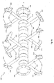
- Fig. 1 shows a perspective internal view of apparatus 100 for treating organic mass.
- Apparatus 100 comprises chamber 106 for containing a mixture of organic mass and one or more micro-organisms selected to degrade the organic mass.
- Chamber 106 is also called the treatment zone as this is the place where organic mass will be treated.
- chamber 106 is a U-shaped cylindrical container.
- the mixture is agitated by agitation means 120 provided in chamber 106.
- Agitation means 120 comprises rotatable shaft 114, a plurality of agitator arms 116, and paddle 118 connected to each agitator arm 116.
- Shaft 114 is extending through a central bore of chamber 106 and rotatable about its longitudinal axis x1 driven by motor 108.
- the central bore of chamber 106 is substantially parallel to the ground.
- the rotation speed of shaft 114 can be adjusted via gearbox 107.
- Motor 108 and gearbox 107 are linked by V-belt 113.
- Paddle 118 may include a member 119 to form a means for directing the mixture within chamber 106.
- Organic mass to be treated is introduced into chamber 106 by conveyor belt 101.
- Conveyor belt 101 transports the organic mass to inlet 103 and into chamber 106.
- the micro-organisms used to degrade the organic mass are also introduced into chamber 106 via inlet 103.
- Apparatus 100 may have one or more air blower 105 that provides oxygen to the mixture to accelerate the aerobic degradation of the organic mass. Any excess or by-product gases generated during the treatment of the organic mass may be expelled from chamber 106 via air vent 104.
- the mixture in chamber 106 is heated by heating oil which encapsulates the entire or at least a portion of the perimeter of chamber 106 by oil circulation pump 109.
- the temperature of the heating oil is maintained in thermal oil tank 102 by heating element 112.
- the treated organic mass is discharged from chamber 106 via outlet 110 which may be operated by pneumatic valve.
- the discharged fertilizer (treated organic mass) is transported away from apparatus 100 by conveyor belt 111.
- agitator arms 116 are extending from the longitudinal axis x1 of shaft 114 (or 314).
- Agitator arms 116 (or 316) may extend at any suitable angles with respect to the longitudinal axis x1 of shaft 114 (or 314).
- agitator arms 116 (or 316) are substantially perpendicular to the longitudinal axis x1 of shaft 114 (or 314).
- agitator arm 116 may extend from shaft 114 (or 314) at an angle from about 70° to about 110°, or from about 70° to about 100°, or from about 70° to about 90°, or from about 80° to about 110°, or from about 90° to about 110°, with respect to the longitudinal axis x1 of shaft 114 (or 314).
- ten agitator arms 116 (or 316) are extending from shaft 114 (or 314).
- Paddle 118 is connected to each agitator arm 116 (or 316) for agitating and moving the mixture in chamber 106.
- Paddle 118 (or 318) may be of any suitable shapes and sizes, e.g. it can be a substantially rectangular planar blade.
- each agitator arm 116 (or 316) may have more than one paddle 118 (or 318) connected to it.
- each agitator arm 116 (or 316) may have two paddles 118 (or 318).
- Paddle 118 (or 318) may be connected to each agitator arm 116 (or 316) at any part of paddle 118 (or 318) which is suitable for agitating or moving the mixture.
- paddle 118 is connected to agitator arm 116 (or 316) at about the middle part of paddle 118 (or 318) (see Fig. 4d ). Further, paddle 118 (or 318) may be connected to any part along the longitudinal axis x2 of agitator arm 116 (or 316). Preferably, paddle 118 (or 318) is connected adjacent to an end portion of agitator arm 116 (or 316) opposed to the end connected to shaft 114 (or 314). Paddle 118 (or 318) that connected to the end portion of agitator arm 116 (or 316) and proximal to the inner wall of chamber 106 promotes homogenous mixing. The gap between paddle 118 (or 318) and the inner wall of chamber 106 may be 15 mm.
- Paddle 118 (or 318 as shown in Figs. 4c and 4d ) is arranged to make a first angle ⁇ with respect to the longitudinal axis x2 of agitator arm 116 (or 316) and a second angle ⁇ with respect to the longitudinal axis x1 of shaft 114 (or 314).
- the first angle ⁇ of paddle 118 (or 318) is within a range of about 70° to about 110°.
- the first angle ⁇ is about 90°, i.e. paddle 118 (or 318) is substantially perpendicular to the longitudinal axis x2 of agitator arm 116 (or 316).
- the first angle ⁇ may be a value from about 70° to about 110°, or from about 70° to about 100°, or from about 70° to about 90°, or from about 80° to about 110°, or from about 90° to about 110°.
- the first angle ⁇ of paddle 118 of each agitator arm 116 may be angled at the same or different angle.
- the second angle ⁇ of paddle 118 is within a range of 0° to 180°.
- the longitudinal axis of paddle 118 (or 318) is substantially parallel to the longitudinal axis x1 of shaft 114 (or 314).
- Each paddle 118 (or 318) is angled at a different second angle ⁇ such that the mixture is directed in different directions to enable thorough mixing.
- the second angle ⁇ sequentially runs from 0° to 180°. In some embodiments, the second angle ⁇ sequentially runs from 0°, 45°, 90°, 135° to 180°. As such, the mixture directed along a path of travel by one paddle may be scooped up by the next sequentially angled paddle. Accordingly, the sequentially angled paddles advantageously ensure that the mixture is constantly agitated.
- Paddle 118 may have member 119 (or 319) connected to it to form a means for directing the mixture within chamber 106.
- Member 119 (or 319) may be of any suitable shapes and sizes, such as a substantially rectangular planar structure.
- Member 119 (or 319) may be integral to paddle 118 (or 318) to form a single piece, or coupled/attached to paddle 118 (or 318).
- paddle 118 (or 318) and member 119 (or 319) rotate in motion together with rotatable shaft 114 (or 314) to direct a portion of the mixture along a direction of travel.
- Member 119 (or 319) is disposed on paddle 118 (or 318) in a plane and angled from the plane of paddle 118 (or 318) such that the mixture is caught by paddle 118 (or 318) and member 119 (or 319) and directed along a direction of travel. Hence, member 119 (or 319) provides an enhanced scooping effect of paddle 118 (or 318). Member 119 (or 319) may be disposed on paddle 118 (or 318) in a plane, at an angle from about 70° to about 110°, or from about 70° to about 100°, or from about 70° to about 90°, or from about 80° to about 110°, or from about 90° to about 110°, with respect to paddle 118 (or 318).
- member 119 (or 319) is substantially perpendicular to paddle 118 (or 318) in a plane such that paddle 118 (or 318) and member 119 (or 319) form a substantially T-shaped structure configuration (see Fig. 4d ).
- member 119 (or 319) is disposed on an edge of paddle 118 (or 318) in a plane, forming a substantially L-shaped structure.
- paddle 118 disposed proximal to the inner surface (wall) of chamber 106 to aid in moving unmixed pockets of the mixture proximal to the sides of chamber 106.
- Paddle 118 prevents the mixture from being pushed to the sides or the top of chamber 106.
- paddle 118 may advantageously prevent the mixture from spilling out of chamber 106 during mixing.
- Paddle 118 (or 318) may be integrally formed with agitator arm 116 (or 316), and agitator arm 116 (or 316) may be integrally formed with rotatable shaft 114 (or 314).
- rotatable shaft 114 (or 314), agitator arm 116 (or 316) and paddle 118 (or 318) may be coupled to each other.
- agitator arm 116 (or 316) may be welded onto rotatable shaft 114 (or 314), and paddle 118 (or 318) is welded onto agitator arm 116 (or 316).
- agitation means 120 is made from a material capable of withstanding mixing or agitation of dense material.
- agitation means 120 may be made of stainless steel, such as SUS 304 grade stainless steel.
- Agitator arms 116 may be regularly / evenly spaced or arranged at predetermined intervals ⁇ along the length of rotatable shaft 114 (or 314). This configuration advantageously allows the mixing of the mixture in chamber 106 to be maximized.
- the distance between each agitator arm 116 (or 316) disposed along the length of rotatable shaft 114 (or 314) depends on the capacity of chamber 106 of apparatus 100.
- the distance ⁇ between each agitator arm 116 (or 316) may be from about 200 mm to about 450 mm.
- the distance between each agitator arm is about 252.5 mm.
- the distance between each agitator arm 116 is about 415 mm.
- the distance ⁇ is about 277 mm for a chamber of 22,000 liters, and about 367 mm for a chamber of 22,000 liters.
- the longitudinal length of shaft 114 (or 314) may range from about 3.8 m (e.g. for a chamber of 22,000 L) to about 5 m (e.g. for a chamber of 80,000 L).
- the diameter of shaft 114 may range from about 26 cm (e.g. for a chamber of 22,000 L) to about 35 cm (e.g. for a chamber of 80,000 L).
- Agitator arms 116 may be regularly spaced around the circumference of rotatable shaft 114 (or 314) to maximize the mixing of the mixture in chamber 106.
- two agitator arms 116 may offset from each other at an angle of about 70° to about 110°.
- agitator arms 316 are offset from each other at about 90°.
- Agitator arm 116 may be of any suitable shapes and sizes that sufficient to move or agitate the mixture in chamber 106.
- agitator arm 116 (or 316) has a rod-like shape.
- agitator arm 116 (or 316) is of a fin-like shape.
- the edges of agitator arm 116 (or 316) are sharp or tapered and able to cut through the organic mass to maximize the mixing of the mixture.
- the mixing increases the surface area of the organic mass that is exposed to the micro-organisms, and thus increases the contact of the organic mass with the micro-organisms.
- Rotatable shaft 114 may be rotated by any means known in the art, such as a motor.
- the motor should have sufficient power to rotate shaft 114 (or 314) to sufficiently agitate or mix the mixture in chamber 106.
- the organic mass may be viscous and/or dense and thus may be difficult to mix.
- the rotation speed of shaft 114 (or 314) should be configured to ensure sufficient agitation of the mixture.
- the rotation speed is adjustable depending on the type of organic mass used.
- agitation means 120 (or 320) (which comprises rotatable shaft 114 (or 314), agitator arms 116 (or 316) and paddles 118 (or 318)) is more cost effective than having a plurality of independent agitators or paddles disposed in the treatment zone.
- the cost of constructing apparatus 100 is lower than the cost of constructing an apparatus having a plurality of independent agitators or paddles.
- the operational cost of apparatus 100 may be lower than that of an apparatus with a plurality independent agitators or paddles because of lower energy consumption and lower maintenance cost due to fewer moving parts in apparatus 100.
- chamber 106 is an enclosed cylindrical chamber.
- chamber 106 may be in any other suitable shapes.
- a cylindrical chamber may reduce the possibility of dead spaces, i.e. unmixed pockets, which may be present in the chamber with angular corners.
- Chamber 106 may be of any capacity ranging from about 4,000 liters (L) to about 80,000 liters (L).
- chamber 106 may have a capacity of 4,000L, 22,000L, 60,000L or 80,000L.
- the treatment of organic mass may be performed on an industrial scale using apparatus 100, and does not require an excessive amount of space. Further, any foul odors or gaseous emissions can be prevented from being released to the surroundings.
- apparatus 100 may be situated near the waste generation site for increased convenience and accessibility to the organic biomass.
- apparatus 100 may be situated in built-up areas.
- the capacity of apparatus 100 may be scaled down to as low as 10 liters, and scaled up to as high as 400,000 liters.
- Chamber 106 may be fabricated from any suitable material which is capable of withstanding acidic or alkaline mixtures, such as the pH of empty fruit bunch (EFB) is about pH 6, the pH of citrus peel is about pH 4, and the pH of chicken manure is about pH 9.
- chamber 106 may be made of stainless steel, such as SUS 304 grade stainless steel.
- chamber 106 may be made of a polymer material which includes, but are not limited to, an epoxy, vinyl esters, polyester thermosetting plastics or phenol formaldehyde resins.
- the polymer material may be a composite reinforced with fibres. Examples of fibres that may be used include, but are not limited to, glass, carbon, aramid, paper, wood or asbestos.
- chamber 106 is made of fibre-reinforced plastic.
- the inner wall of chamber 106 may comprise stud-like structures extending into the treatment zone.
- the stud-like structures may be spikes.
- the stud-like structures are able to break up the organic mass agitated by agitation means 120 in chamber 106 and thus increase the surface area of the organic mass that is exposed to the micro-organisms. Hence, maximum contact of the organic mass with the micro-organisms is ensured.
- Apparatus 100 may further comprise means for controlling the environment within chamber 106.
- the environment controlling means may include temperature control means, pH control means, moisture control means and/or aeration means.
- Apparatus 100 may also comprise a control unit for controlling the environment within chamber 106.
- the temperature control means is in thermal communication with chamber 106 to control the temperature of the mixture.
- the temperature control means may be configured to control the temperature of the mixture of organic mass and micro-organisms located in chamber 106.
- the temperature control means is capable of controlling the temperature of the mixture to a range of temperatures, such as from about 20°C to about 150°C.
- the temperature control means provides precise temperature control of chamber 106.
- the precise temperature control of chamber 106 ensures that the metabolic activity of the micro-organisms operates at an optimal level to treat the organic mass.
- the treated organic mass i.e. organic fertilizer, with high NPK values (e.g. 6 and above) can advantageously be achieved in less than 48 hours, or less than 36 hours, or less than 24 hours, or less than 12 hours.
- the temperature control means may comprise heating means and cooling means.
- the heating means may be any suitable means known in the art.
- the heating means may comprise one or more electrical heating elements, or one or more heat exchangers, through which, for example, heating oil is circulated.
- the heating means may also comprise of electric or gas heaters, or jets of hot air which can be directed specifically at chamber 106.
- the heating means may be a steam generator.
- the heating means may also be a waste heat source, a solar heat source or a geothermal heat source. Exemplary waste heat sources include flue gases from gas turbines in power plants and incinerators, process gases of chemical and metallurgical operations and waste heat from other industrial processes.
- the heating means may further be insulated using any suitable insulation techniques known in the art to minimize heat loss. Typically, the heating means is capable of heating the organic mass to about 80°C to about 150°C.
- the cooling means may be any suitable means known in the art.
- the cooling means may be a stream of cold nitrogen gas.
- the cooling means may also comprise of one or more heat exchangers.
- the cooling means is capable of reducing the temperature of the organic mass to about 35°C to about 75°C.
- the pH control means may adjust the pH of the mixture.
- the pH may be controlled at values of about 3 to about 10. If the pH is higher or lower than the desired value, an appropriate pH buffer such as a phosphate buffer, an acetate buffer, a Tris buffer, and the like, may be added.
- the moisture control means maintains the moisture level of the mixture of organic mass and micro-organisms at a suitable level.
- the degradation of organic mass by the micro-organisms is enhanced by the presence of moisture in the mixture at levels of about 10 wt% to about 22 wt%.
- the moisture levels of the mixture may be adjusted by means that are well known to those skilled in the art. For example, if the moisture content of the mixture is too high, hot air may be blown over the mixture via air blowers. Alternatively, the organic mass may be blended with other organic mass that has lower moisture content such as rice husk, rice straw, saw dust, and the like, to achieve the desired moisture content level. Conversely, if the moisture content of the mixture is too low, water may be sprayed onto the mixture via spray bars.
- apparatus 100 may comprise aeration means for aerating chamber 106 during treatment of the organic mass.
- Aerating the organic mass in chamber 106 increases the rate of aerobic degradation and decreases the rate of anaerobic degradation of the organic mass.
- predominantly aerobic conditions accelerate the degradation rate of organic mass by the action of micro-organisms.
- the emission of the foul-smelling by-products from the anaerobic degradation process, such as methane is reduced. As methane emissions are typically regulated by national environmental agencies, the reduction of methane emission aids in meeting emission regulation standards.
- the aeration means may be an air blower.
- the air blower may deliver air at a pressure sufficient to ensure that the air reaches the organic mass quickly and easily.
- the air pressure required is dependent on the capacity of apparatus 100.
- the number of air blowers used may range from two to eight.
- the air may be provided continuously during the treatment, or may be provided periodically according to a pre-determined regime.
- apparatus 100 may comprise four air blowers 105 with each providing an air pressure of 37 millimeter water (mmAq).
- mmAq millimeter water
- Apparatus 100 may also comprise one or more air vent 104 for expelling excess gas from apparatus 100.
- Apparatus 100 has inlet 103 for receiving organic mass to be treated.
- the organic mass may be manually introduced into chamber 106 or automatically introduced into chamber 106 by conveyor belt 101.
- Apparatus has outlet 110 through which the treated organic mass, i.e. organic fertilizer, is offloaded.
- the treated organic mass may be manually offloaded from apparatus 100 or automatically offloaded and transferred out from apparatus 100 by conveyor belt 111.
- the micro-organisms useful for the treatment and/or degradation of the organic mass are those that are capable of degrading carbon compounds or fixing nitrogen compounds.
- mixed cultures of the micro-organisms are used in order to obtain a broad spectrum of degradation or fixation.
- the selection of the micro-organisms is dependent on the type of organic mass that is to be treated.
- the micro-organisms selected to degrade the organic mass may be selected from the group consisting of Bacillus sp. micro-organisms, Pseudomonas sp. micro-organisms, Bifidobacterium sp. micro-organisms, Lactobacillus sp. micro-organisms, Streptomyces sp.
- the one or more micro-organisms are selected from the group consisting of Bacillus sp. micro-organisms, Pseudomonas sp. micro-organisms, Bifidobacterium sp. micro-organisms, Lactobacillus sp. micro-organisms, Streptomyces sp. micro-organisms, Corynebacterium sp. micro-organisms and mixtures thereof.
- the treated organic mass, or organic fertilizer may have an NPK value of more than 6.
- the NPK value determines the amount of nitrogen (N), phosphorous (P) and potassium (K) present in the organic fertilizer. These nutrients are typically lost to the environment when conventional composting methods and systems are used.
- high NPK values indicate an organic fertilizer that possesses a high amount of nutrients and is therefore a fertilizer of high quality.
- apparatus 100 may produce the matured organic fertilizer with high NPK values (6 and above) within one day.
- Apparatus 100 may be disposed on an elevated support, such as legs or stands.
- the support may be designed to carry the weight of the entire apparatus. Accordingly, the size of the support is dependent on the size of the apparatus.
- Apparatus 100 may comprise a ladder and an operation platform for easy access to, for example, inlet 103.
- Apparatus 100 may further comprise safety features such as an emergency stop device.
- the emergency stop device may halt the power to apparatus 100 in the event of an emergency, for example, a run-away reaction or when the agitation means is jammed.
- Other safety features may include safety railings along the ladder and the operation platform.
- Apparatus 100 may further comprise a system for recycling ammonia generated from the treated organic mass.
- the system comprises means for collecting ammonia generated from the treatment of the organic mass and means for distributing the collected ammonia.
- the distributing means is fluidly connected to the collecting means for distributing the collected ammonia.
- the collected ammonia may be recycled back to chamber 106 to boost the NPK value of the treated organic mass.
- the collected ammonia may be recycled to the treated organic mass outside of apparatus 100.
- the recycled ammonia boosts the NPK value of the organic mass.
- the emitted ammonia by-product is reused.
- the collecting means and the distributing means may be of any suitable means.
- the collecting means and the distribution means are pipes.
- the pipes should be made from a material capable of withstanding ammonia.
- the pipes are made of stainless steel, such as SUS 304 grade stainless steel.
- the pipes may be made of a polymer material which includes, but are not limited to, an epoxy, vinyl esters, polyester thermosetting plastics or phenol formaldehyde resins.
- the polymer material may be a composite reinforced with fibres. Examples of fibres that may be used include, but are not limited to, glass, carbon, aramid, paper, wood or asbestos.
- the pipes are made of fibre reinforced plastic.
- the system may further comprise testing means to monitor the percentage recovery of ammonia.
- the testing means may be any suitable means known in the art.
- the system may comprise a bio-filter.
- the bio-filter may be one that is known in the art. The system recovers more than 80% of the ammonia emitted from the degradation of the organic mass.
- Apparatus 100 may be modular in which it comprises two or more chambers 106.
- the two or more chambers 106 may be arranged parallel to each other or in any other arrangements.
- the use of two or more chambers may increase the throughput of the organic mass to be treated.
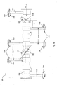
- Figs. 2a , 2b , 3a and 3b show apparatus 200 comprises two chambers 206 arranged parallel to each other to increase the throughput of the organic mass to be treated.
- the components present in apparatus 200 are similar to the components present in apparatus 100.
- the organic mass to be treated is introduced into the respective chambers 206 of apparatus 200 by conveyor belt 201.
- Conveyor belt 201 has two ends above inlets 203 of the respective chambers 206 for delivery the organic mass into chambers 206.
- Conveyor belt 201 has a T-shaped configuration. Other suitable shapes and means for transferring the organic mass into inlets 203 are possible.
- Each chamber 206 possesses agitation means 220. Similar to agitation means 120, agitation means 220 comprises rotatable shaft 214, agitator arms 216 and paddles 218. Rotatable shaft 214 is rotated about its longitudinal axis by motor 208 at one end of chamber 206 and is fixed at the other end of chamber 206 by bearing 217 (see Figs. 3a and 3b ).
- the mixture of organic mass and micro-organisms in chamber 206 is heated by heating oil encapsulating the entire or at least a portion of the perimeter of chamber 206.
- the heating oil is heated by a thermal oil tank (not shown).
- the treated organic mass is offloaded via outlet 215 and transported away by conveyor belt 211.
- Fig. 4a , 4b and 4c show different views of agitation means 320 in accordance with an embodiment of the present invention.
- Fig. 4a shows agitation means 320 comprises ten agitator arms 316 extending from rotatable shaft 314.
- Agitation means 320 may have any suitable numbers of agitator arms 316, depending on the capacity of the treatment chamber. For examples, a chamber of 22,000 L may have 10 to 14 agitator arms 316, and a chamber of 80,000 L may have 14 to 16 agitator arms 316.
- Paddle 318 is connected to each agitator arm 316.
- Each agitator arm 316 is substantially perpendicularly extends from the longitudinal axis of rotatable shaft 314.
- Flanges 324 connect two ends of rotatable shaft 314 to the external of treatment zone.
- the side end view of agitation means 320 is shown in Fig. 4b . It can be seen from Fig. 4b that agitator arms 316 are offset from each other at about 90°.
- the top view of agitation means 320 is shown in Fig. 4c .
- the distance ⁇ between two agitator arms 316 along the length of rotatable shaft 314 is depends on the capacity of the apparatus. For example, when the disclosed apparatus has a chamber of 4,000 L capacity, the distance ⁇ is about 252.5 mm. For another example, the distance ⁇ is about 415 mm when the apparatus has a chamber of 22,000 L or 80,000 L capacity.
- FIG. 4d Close-up diagrams of paddle 318 disposed at an end portion of agitator arm 316 are shown in Fig. 4d .
- Member 319 is connected to paddle 318 to form a T-shaped structure for directing the mixture.
- Member 319 may also be connected to an edge of paddle 318 to form a L-shaped structure.
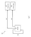
- FIG. 5 A schematic diagram of system 500 for recycling ammonia generated from the treatment of the organic mass by the apparatus as disclosed above is shown in Fig. 5 .
- Pipes 502, 504 and 506 connect chamber 106 (or 206) of apparatus 100 (or 200) to other areas.
- pipe 502 connects treatment zone 106 to testing means 400
- pipe 504 connects chamber 106 to the finished fertilizer product 300
- pipe 506 recycles the generated ammonia back to chamber 106.
- Pipe 502 directs the ammonia to testing means 400 so that the amount of ammonia recovered can be monitored.
- Pipe 504 directs the ammonia to the finished fertilizer product 300 to boost the NPK value of product 300.
- Pipe 506 recycles the ammonia back to chamber 106 as a source of nutrients for the treatment of organic mass.
Priority Applications (2)
| Application Number | Priority Date | Filing Date | Title |
|---|---|---|---|
| PL13863573T PL2931411T3 (pl) | 2012-12-14 | 2013-12-10 | Urządzenie do obróbki masy organicznej |
| HRP20200909TT HRP20200909T1 (hr) | 2012-12-14 | 2020-06-08 | Uređaj za obradu organske mase |
Applications Claiming Priority (2)
| Application Number | Priority Date | Filing Date | Title |
|---|---|---|---|
| GB201222641A GB201222641D0 (en) | 2012-12-14 | 2012-12-14 | Apparatus and system for treating organic mass |
| PCT/SG2013/000524 WO2014092648A1 (en) | 2012-12-14 | 2013-12-10 | Apparatus and system for treating organic mass |
Publications (3)
| Publication Number | Publication Date |
|---|---|
| EP2931411A1 EP2931411A1 (en) | 2015-10-21 |
| EP2931411A4 EP2931411A4 (en) | 2016-12-28 |
| EP2931411B1 true EP2931411B1 (en) | 2020-03-25 |
Family
ID=47630791
Family Applications (1)
| Application Number | Title | Priority Date | Filing Date |
|---|---|---|---|
| EP13863573.5A Active EP2931411B1 (en) | 2012-12-14 | 2013-12-10 | Apparatus for treating organic mass |
Country Status (24)
| Country | Link |
|---|---|
| US (1) | US10155699B2 (es) |
| EP (1) | EP2931411B1 (es) |
| JP (1) | JP6362221B2 (es) |
| KR (1) | KR102224761B1 (es) |
| CN (1) | CN104023835B (es) |
| AU (1) | AU2013344337B2 (es) |
| BR (1) | BR112015012910A2 (es) |
| CA (1) | CA2893742C (es) |
| CY (1) | CY1123323T1 (es) |
| DK (1) | DK2931411T3 (es) |
| ES (1) | ES2800448T3 (es) |
| GB (1) | GB201222641D0 (es) |
| HK (1) | HK1201490A1 (es) |
| HR (1) | HRP20200909T1 (es) |
| HU (1) | HUE050799T2 (es) |
| MY (1) | MY180029A (es) |
| NZ (1) | NZ625033A (es) |
| PH (1) | PH12015501287A1 (es) |
| PL (1) | PL2931411T3 (es) |
| PT (1) | PT2931411T (es) |
| SG (1) | SG11201503339PA (es) |
| UA (1) | UA110416C2 (es) |
| WO (1) | WO2014092648A1 (es) |
| ZA (1) | ZA201504746B (es) |
Families Citing this family (10)
| Publication number | Priority date | Publication date | Assignee | Title |
|---|---|---|---|---|
| CN104387140B (zh) * | 2014-12-01 | 2016-10-26 | 四川凯尔丰农业科技有限公司 | 一种翻料板及其有机生物肥生产发酵料翻料机构 |
| JP5865539B1 (ja) * | 2015-05-21 | 2016-02-17 | 株式会社三和商会 | 微細分散複合化装置及び微細分散複合化方法 |
| CN106395394B (zh) * | 2016-08-30 | 2018-07-27 | 安徽安特食品股份有限公司 | 一种制酒用曲块自动码放平台 |
| CN106395398B (zh) * | 2016-08-30 | 2018-11-27 | 安徽安特食品股份有限公司 | 一种酒曲曲块入库码放设备 |
| US10676907B2 (en) * | 2017-06-19 | 2020-06-09 | David Jay MAST | Organic waste treatment process and device |
| CN107486071A (zh) * | 2017-07-10 | 2017-12-19 | 云南云天化农业科技股份有限公司 | 一种配肥设备 |
| WO2019136544A1 (en) * | 2018-01-11 | 2019-07-18 | Tri-Form Poly, Inc. | Rotary composter with control system and method of composting |
| CN111774398B (zh) * | 2020-06-11 | 2023-11-24 | 广西力源宝科技有限公司 | 厨余垃圾生态处理终端及处理方法 |
| KR102636663B1 (ko) | 2021-09-30 | 2024-02-14 | 이태건 | 유기물 처리 장치 |
| CN113897400A (zh) * | 2021-11-26 | 2022-01-07 | 西北农林科技大学 | 一种香菇菌糠好氧发酵生产腐殖酸的方法 |
Family Cites Families (30)
| Publication number | Priority date | Publication date | Assignee | Title |
|---|---|---|---|---|
| FR2360E (fr) | 1904-03-09 | Giovanni Ceschina | Transformation de la machine à empater, à palettes hélicoidales tournant dans la machine, pour empater et pétrir en meme temps | |
| GB1237630A (en) | 1968-05-07 | 1971-06-30 | Ceskoslovenska Akademie Ved | Apparatus for bringing a melt or solid substances into co-current contact with hot gaseous media |
| US4483625A (en) * | 1981-02-10 | 1984-11-20 | Technovators, Inc. | Continuous solid particulate mixer conveyor having variable capacity |
| JPH0710337B2 (ja) | 1988-07-04 | 1995-02-08 | 三洋化成工業株式会社 | 撹拌装置 |
| JPH04130078A (ja) | 1990-09-20 | 1992-05-01 | Etoro:Kk | 有機性廃棄物の高速発酵処理機 |
| US5427947A (en) * | 1993-03-25 | 1995-06-27 | Dalos; David E. | Environmental chamber and method for composting solid waste |
| JPH07124538A (ja) * | 1993-11-01 | 1995-05-16 | Hitachi Ltd | 固形有機廃棄物の処理装置 |
| JPH091112A (ja) | 1995-06-16 | 1997-01-07 | Aikawa Iron Works Co Ltd | 有機廃棄物処理装置及び有機廃棄物の処理方法 |
| JPH0977581A (ja) * | 1995-09-14 | 1997-03-25 | Hitachi Ltd | 有機系廃棄物のコンポスト化装置 |
| US5981269A (en) * | 1997-08-20 | 1999-11-09 | Park; Joon | Apparatus for fermenting and composting food waste |
| US6139793A (en) * | 1997-09-05 | 2000-10-31 | Hydroclave Systems Corporation | Waste treatment control system |
| DE29906703U1 (de) | 1999-04-15 | 1999-08-12 | Unibautech Grossenhainer Masch | Mischer zur Herstellung von Suspensionen |
| JP2001072483A (ja) * | 1999-09-02 | 2001-03-21 | Ishigaki Co Ltd | コンポストのph調整方法 |
| JP2001347245A (ja) * | 2000-06-07 | 2001-12-18 | Kazuo Kikuchi | 生ごみ消滅装置と消滅方法 |
| DE10029668A1 (de) * | 2000-06-23 | 2002-01-03 | Biosal Anlagenbau Gmbh | Bioreaktor zur mikrobiellen Konvertierung stückiger und/oder pastöser Stoffe |
| WO2002024860A1 (en) | 2000-09-23 | 2002-03-28 | Mcnelly James J | Recirculating composting system |
| JP2002331275A (ja) * | 2001-05-09 | 2002-11-19 | Kazu Kumagai | 生ゴミ処理装置 |
| JP3644911B2 (ja) * | 2001-07-10 | 2005-05-11 | 株式会社湘南ぴゅあ | 食品残渣の処理方法 |
| JP2004057946A (ja) * | 2002-07-29 | 2004-02-26 | Gold Hakko Gijutsu Kenkyusho:Kk | 発酵処理槽及び発酵処理装置 |
| JP2004130181A (ja) | 2002-10-09 | 2004-04-30 | Asahi Recycle Support Kk | 有機廃棄物の処理装置における攪拌装置 |
| CN1274919C (zh) * | 2003-01-13 | 2006-09-13 | 童铭棻 | 一种排泄物的处理方法以及使用该方法的环保马桶 |
| DE102004014163A1 (de) * | 2003-03-17 | 2004-12-09 | Behrendt, Gerhard, Prof.Dr. | Verfahren und Vorrichtung zur Herstellung von Recyclat-Polyolen aus Polyestern |
| DE602004020686D1 (de) * | 2004-05-25 | 2009-05-28 | Koai Industry Co Ltd | Abfallbehandlungsvorrichtung |
| DE102008017045B9 (de) * | 2008-04-03 | 2012-07-05 | Umicore Ag & Co. Kg | Rührsystem und Verfahren zum Homogenisieren von Glasschmelzen |
| US20100034050A1 (en) * | 2008-08-11 | 2010-02-11 | Gary Erb | Apparatus and Method for Cultivating Algae |
| KR100898750B1 (ko) | 2008-09-22 | 2009-05-25 | 박충길 | 유기성폐기물 처리기 |
| JP5646491B2 (ja) * | 2009-09-04 | 2014-12-24 | 株式会社ツカサ | 粉粒体攪拌装置 |
| GB2478929B (en) * | 2010-03-23 | 2013-08-14 | Biomax Technologies Pte Ltd | Treatment of organic waste |
| CN201776104U (zh) * | 2010-08-20 | 2011-03-30 | 江苏隆昌化工有限公司 | 一种搅拌釜 |
| US20120252107A1 (en) * | 2011-03-31 | 2012-10-04 | Tom Self | Bio-Reactor System and Method for Composting Food Waste |
-
2012
- 2012-12-14 GB GB201222641A patent/GB201222641D0/en not_active Ceased
-
2013
- 2013-10-12 UA UAA201405447A patent/UA110416C2/ru unknown
- 2013-12-10 AU AU2013344337A patent/AU2013344337B2/en active Active
- 2013-12-10 PT PT138635735T patent/PT2931411T/pt unknown
- 2013-12-10 MY MYPI2014701247A patent/MY180029A/en unknown
- 2013-12-10 PL PL13863573T patent/PL2931411T3/pl unknown
- 2013-12-10 DK DK13863573.5T patent/DK2931411T3/da active
- 2013-12-10 CA CA2893742A patent/CA2893742C/en active Active
- 2013-12-10 EP EP13863573.5A patent/EP2931411B1/en active Active
- 2013-12-10 SG SG11201503339PA patent/SG11201503339PA/en unknown
- 2013-12-10 KR KR1020157017553A patent/KR102224761B1/ko active IP Right Grant
- 2013-12-10 US US14/358,466 patent/US10155699B2/en active Active
- 2013-12-10 JP JP2015547895A patent/JP6362221B2/ja active Active
- 2013-12-10 BR BR112015012910A patent/BR112015012910A2/pt active Search and Examination
- 2013-12-10 HU HUE13863573A patent/HUE050799T2/hu unknown
- 2013-12-10 CN CN201380003906.2A patent/CN104023835B/zh active Active
- 2013-12-10 WO PCT/SG2013/000524 patent/WO2014092648A1/en active Application Filing
- 2013-12-10 ES ES13863573T patent/ES2800448T3/es active Active
- 2013-12-10 NZ NZ625033A patent/NZ625033A/en unknown
-
2015
- 2015-02-27 HK HK15101971.4A patent/HK1201490A1/xx unknown
- 2015-06-05 PH PH12015501287A patent/PH12015501287A1/en unknown
- 2015-07-01 ZA ZA2015/04746A patent/ZA201504746B/en unknown
-
2020
- 2020-06-08 HR HRP20200909TT patent/HRP20200909T1/hr unknown
- 2020-06-23 CY CY20201100574T patent/CY1123323T1/el unknown
Non-Patent Citations (1)
| Title |
|---|
| None * |
Also Published As
| Publication number | Publication date |
|---|---|
| NZ625033A (en) | 2016-10-28 |
| CA2893742C (en) | 2021-03-23 |
| PH12015501287B1 (en) | 2015-08-24 |
| BR112015012910A2 (pt) | 2017-07-11 |
| HUE050799T2 (hu) | 2021-01-28 |
| ES2800448T3 (es) | 2020-12-30 |
| EP2931411A4 (en) | 2016-12-28 |
| CY1123323T1 (el) | 2021-12-31 |
| ZA201504746B (en) | 2016-06-29 |
| CN104023835A (zh) | 2014-09-03 |
| PT2931411T (pt) | 2020-06-25 |
| HK1201490A1 (en) | 2015-09-04 |
| PH12015501287A1 (en) | 2015-08-24 |
| WO2014092648A1 (en) | 2014-06-19 |
| JP2016506295A (ja) | 2016-03-03 |
| US10155699B2 (en) | 2018-12-18 |
| AU2013344337B2 (en) | 2017-12-21 |
| SG11201503339PA (en) | 2015-05-28 |
| KR20150094662A (ko) | 2015-08-19 |
| CA2893742A1 (en) | 2014-06-19 |
| JP6362221B2 (ja) | 2018-07-25 |
| KR102224761B1 (ko) | 2021-03-08 |
| EP2931411A1 (en) | 2015-10-21 |
| GB201222641D0 (en) | 2013-01-30 |
| HRP20200909T1 (hr) | 2020-09-04 |
| UA110416C2 (en) | 2015-12-25 |
| CN104023835B (zh) | 2018-01-23 |
| DK2931411T3 (da) | 2020-06-29 |
| AU2013344337A1 (en) | 2014-07-03 |
| MY180029A (en) | 2020-11-20 |
| PL2931411T3 (pl) | 2020-09-07 |
| US20160347676A1 (en) | 2016-12-01 |
Similar Documents
| Publication | Publication Date | Title |
|---|---|---|
| EP2931411B1 (en) | Apparatus for treating organic mass | |
| CA2793923C (en) | Treatment of organic waste | |
| KR101359897B1 (ko) | 분뇨를 이용한 유기질 비료의 제조방법 | |
| KR102063120B1 (ko) | 유기성 폐기물을 속성 건조 발효한 퇴비화 장치 및 그 방법 | |
| KR20020086743A (ko) | 유기 폐기물의 처리 방법 및 그 장치 | |
| CN109020664A (zh) | 一种有机废弃物仓式腐熟发酵设备 | |
| CN109134023A (zh) | 一种有机废弃物仓式腐熟发酵方法 | |
| CN209113779U (zh) | 一种有机废弃物仓式腐熟发酵设备 | |
| KR0185256B1 (ko) | 열 절약형 회전식 퇴비 건조발효장치 | |
| KR200438385Y1 (ko) | 유기성 고형물의 자원화를 위한 다단 적재식 입상형 원통퇴비발효조 | |
| TWI668200B (zh) | 有機廢棄物倉式腐熟發酵方法 | |
| JP2006111479A (ja) | 有機性廃棄物処理システム | |
| CN215209178U (zh) | 一种禽粪无害化自动处理装置 | |
| KR20010071614A (ko) | 유기성 폐기물의 처리방법 및 처리설비 | |
| Malovanyy et al. | Analysis of poultry manure utilisation methods to produce organic fertiliser | |
| Griineklee | Comparing open versus in-vessel composting | |
| WO2020109661A1 (en) | Method for producing bioactive organic products from food and feed productions side streams | |
| CN113896585A (zh) | 一种生物酶快速制备畜禽粪便有机肥工艺系统 | |
| TR2021018111A2 (tr) | Komposttan gübre elde etme tesi̇s ve yöntemi̇ |
Legal Events
| Date | Code | Title | Description |
|---|---|---|---|
| PUAI | Public reference made under article 153(3) epc to a published international application that has entered the european phase |
Free format text: ORIGINAL CODE: 0009012 |
|
| 17P | Request for examination filed |
Effective date: 20150701 |
|
| AK | Designated contracting states |
Kind code of ref document: A1 Designated state(s): AL AT BE BG CH CY CZ DE DK EE ES FI FR GB GR HR HU IE IS IT LI LT LU LV MC MK MT NL NO PL PT RO RS SE SI SK SM TR |
|
| AX | Request for extension of the european patent |
Extension state: BA ME |
|
| DAX | Request for extension of the european patent (deleted) | ||
| REG | Reference to a national code |
Ref country code: DE Ref legal event code: R079 Ref document number: 602013067288 Country of ref document: DE Free format text: PREVIOUS MAIN CLASS: B01F0007040000 Ipc: B01F0007000000 |
|
| A4 | Supplementary search report drawn up and despatched |
Effective date: 20161124 |
|
| RIC1 | Information provided on ipc code assigned before grant |
Ipc: B01F 7/04 20060101ALI20161118BHEP Ipc: B01F 7/00 20060101AFI20161118BHEP Ipc: C05F 17/00 20060101ALI20161118BHEP Ipc: C05F 17/02 20060101ALI20161118BHEP |
|
| GRAP | Despatch of communication of intention to grant a patent |
Free format text: ORIGINAL CODE: EPIDOSNIGR1 |
|
| STAA | Information on the status of an ep patent application or granted ep patent |
Free format text: STATUS: GRANT OF PATENT IS INTENDED |
|
| INTG | Intention to grant announced |
Effective date: 20191011 |
|
| GRAS | Grant fee paid |
Free format text: ORIGINAL CODE: EPIDOSNIGR3 |
|
| GRAA | (expected) grant |
Free format text: ORIGINAL CODE: 0009210 |
|
| STAA | Information on the status of an ep patent application or granted ep patent |
Free format text: STATUS: THE PATENT HAS BEEN GRANTED |
|
| AK | Designated contracting states |
Kind code of ref document: B1 Designated state(s): AL AT BE BG CH CY CZ DE DK EE ES FI FR GB GR HR HU IE IS IT LI LT LU LV MC MK MT NL NO PL PT RO RS SE SI SK SM TR |
|
| REG | Reference to a national code |
Ref country code: GB Ref legal event code: FG4D |
|
| REG | Reference to a national code |
Ref country code: DE Ref legal event code: R096 Ref document number: 602013067288 Country of ref document: DE |
|
| REG | Reference to a national code |
Ref country code: AT Ref legal event code: REF Ref document number: 1247929 Country of ref document: AT Kind code of ref document: T Effective date: 20200415 Ref country code: IE Ref legal event code: FG4D |
|
| REG | Reference to a national code |
Ref country code: HR Ref legal event code: TUEP Ref document number: P20200909T Country of ref document: HR |
|
| REG | Reference to a national code |
Ref country code: CH Ref legal event code: NV Representative=s name: SERVOPATENT GMBH, CH |
|
| REG | Reference to a national code |
Ref country code: FI Ref legal event code: FGE |
|
| REG | Reference to a national code |
Ref country code: PT Ref legal event code: SC4A Ref document number: 2931411 Country of ref document: PT Date of ref document: 20200625 Kind code of ref document: T Free format text: AVAILABILITY OF NATIONAL TRANSLATION Effective date: 20200618 |
|
| REG | Reference to a national code |
Ref country code: DK Ref legal event code: T3 Effective date: 20200623 |
|
| REG | Reference to a national code |
Ref country code: NL Ref legal event code: FP |
|
| REG | Reference to a national code |
Ref country code: SE Ref legal event code: TRGR |
|
| REG | Reference to a national code |
Ref country code: GR Ref legal event code: EP Ref document number: 20200401654 Country of ref document: GR Effective date: 20200716 |
|
| PG25 | Lapsed in a contracting state [announced via postgrant information from national office to epo] |
Ref country code: RS Free format text: LAPSE BECAUSE OF FAILURE TO SUBMIT A TRANSLATION OF THE DESCRIPTION OR TO PAY THE FEE WITHIN THE PRESCRIBED TIME-LIMIT Effective date: 20200325 |
|
| REG | Reference to a national code |
Ref country code: NO Ref legal event code: T2 Effective date: 20200325 |
|
| PG25 | Lapsed in a contracting state [announced via postgrant information from national office to epo] |
Ref country code: LV Free format text: LAPSE BECAUSE OF FAILURE TO SUBMIT A TRANSLATION OF THE DESCRIPTION OR TO PAY THE FEE WITHIN THE PRESCRIBED TIME-LIMIT Effective date: 20200325 Ref country code: BG Free format text: LAPSE BECAUSE OF FAILURE TO SUBMIT A TRANSLATION OF THE DESCRIPTION OR TO PAY THE FEE WITHIN THE PRESCRIBED TIME-LIMIT Effective date: 20200625 |
|
| REG | Reference to a national code |
Ref country code: HR Ref legal event code: T1PR Ref document number: P20200909 Country of ref document: HR |
|
| REG | Reference to a national code |
Ref country code: LT Ref legal event code: MG4D |
|
| PG25 | Lapsed in a contracting state [announced via postgrant information from national office to epo] |
Ref country code: EE Free format text: LAPSE BECAUSE OF FAILURE TO SUBMIT A TRANSLATION OF THE DESCRIPTION OR TO PAY THE FEE WITHIN THE PRESCRIBED TIME-LIMIT Effective date: 20200325 Ref country code: LT Free format text: LAPSE BECAUSE OF FAILURE TO SUBMIT A TRANSLATION OF THE DESCRIPTION OR TO PAY THE FEE WITHIN THE PRESCRIBED TIME-LIMIT Effective date: 20200325 Ref country code: SM Free format text: LAPSE BECAUSE OF FAILURE TO SUBMIT A TRANSLATION OF THE DESCRIPTION OR TO PAY THE FEE WITHIN THE PRESCRIBED TIME-LIMIT Effective date: 20200325 Ref country code: CZ Free format text: LAPSE BECAUSE OF FAILURE TO SUBMIT A TRANSLATION OF THE DESCRIPTION OR TO PAY THE FEE WITHIN THE PRESCRIBED TIME-LIMIT Effective date: 20200325 Ref country code: SK Free format text: LAPSE BECAUSE OF FAILURE TO SUBMIT A TRANSLATION OF THE DESCRIPTION OR TO PAY THE FEE WITHIN THE PRESCRIBED TIME-LIMIT Effective date: 20200325 Ref country code: IS Free format text: LAPSE BECAUSE OF FAILURE TO SUBMIT A TRANSLATION OF THE DESCRIPTION OR TO PAY THE FEE WITHIN THE PRESCRIBED TIME-LIMIT Effective date: 20200725 |
|
| REG | Reference to a national code |
Ref country code: HR Ref legal event code: ODRP Ref document number: P20200909 Country of ref document: HR Payment date: 20201204 Year of fee payment: 8 |
|
| REG | Reference to a national code |
Ref country code: DE Ref legal event code: R097 Ref document number: 602013067288 Country of ref document: DE |
|
| REG | Reference to a national code |
Ref country code: HU Ref legal event code: AG4A Ref document number: E050799 Country of ref document: HU |
|
| PGFP | Annual fee paid to national office [announced via postgrant information from national office to epo] |
Ref country code: DK Payment date: 20201216 Year of fee payment: 8 Ref country code: GR Payment date: 20201216 Year of fee payment: 8 Ref country code: IE Payment date: 20201222 Year of fee payment: 8 Ref country code: PT Payment date: 20201204 Year of fee payment: 8 Ref country code: SE Payment date: 20201216 Year of fee payment: 8 Ref country code: HR Payment date: 20201204 Year of fee payment: 8 Ref country code: MC Payment date: 20201217 Year of fee payment: 8 Ref country code: FI Payment date: 20201216 Year of fee payment: 8 Ref country code: AT Payment date: 20201228 Year of fee payment: 8 Ref country code: NO Payment date: 20201217 Year of fee payment: 8 Ref country code: HU Payment date: 20201219 Year of fee payment: 8 |
|
| PLBE | No opposition filed within time limit |
Free format text: ORIGINAL CODE: 0009261 |
|
| STAA | Information on the status of an ep patent application or granted ep patent |
Free format text: STATUS: NO OPPOSITION FILED WITHIN TIME LIMIT |
|
| REG | Reference to a national code |
Ref country code: AT Ref legal event code: UEP Ref document number: 1247929 Country of ref document: AT Kind code of ref document: T Effective date: 20200325 |
|
| PGFP | Annual fee paid to national office [announced via postgrant information from national office to epo] |
Ref country code: BE Payment date: 20201222 Year of fee payment: 8 |
|
| 26N | No opposition filed |
Effective date: 20210112 |
|
| PGFP | Annual fee paid to national office [announced via postgrant information from national office to epo] |
Ref country code: CY Payment date: 20201208 Year of fee payment: 8 Ref country code: IT Payment date: 20201218 Year of fee payment: 8 |
|
| PG25 | Lapsed in a contracting state [announced via postgrant information from national office to epo] |
Ref country code: SI Free format text: LAPSE BECAUSE OF FAILURE TO SUBMIT A TRANSLATION OF THE DESCRIPTION OR TO PAY THE FEE WITHIN THE PRESCRIBED TIME-LIMIT Effective date: 20200325 |
|
| PG25 | Lapsed in a contracting state [announced via postgrant information from national office to epo] |
Ref country code: LU Free format text: LAPSE BECAUSE OF NON-PAYMENT OF DUE FEES Effective date: 20201210 |
|
| REG | Reference to a national code |
Ref country code: DE Ref legal event code: R079 Ref document number: 602013067288 Country of ref document: DE Free format text: PREVIOUS MAIN CLASS: B01F0007000000 Ipc: B01F0027000000 |
|
| PG25 | Lapsed in a contracting state [announced via postgrant information from national office to epo] |
Ref country code: MT Free format text: LAPSE BECAUSE OF FAILURE TO SUBMIT A TRANSLATION OF THE DESCRIPTION OR TO PAY THE FEE WITHIN THE PRESCRIBED TIME-LIMIT Effective date: 20200325 |
|
| PG25 | Lapsed in a contracting state [announced via postgrant information from national office to epo] |
Ref country code: MK Free format text: LAPSE BECAUSE OF FAILURE TO SUBMIT A TRANSLATION OF THE DESCRIPTION OR TO PAY THE FEE WITHIN THE PRESCRIBED TIME-LIMIT Effective date: 20200325 Ref country code: AL Free format text: LAPSE BECAUSE OF FAILURE TO SUBMIT A TRANSLATION OF THE DESCRIPTION OR TO PAY THE FEE WITHIN THE PRESCRIBED TIME-LIMIT Effective date: 20200325 |
|
| REG | Reference to a national code |
Ref country code: HR Ref legal event code: PBON Ref document number: P20200909 Country of ref document: HR Effective date: 20211210 |
|
| REG | Reference to a national code |
Ref country code: FI Ref legal event code: MAE |
|
| REG | Reference to a national code |
Ref country code: NO Ref legal event code: MMEP Ref country code: DK Ref legal event code: EBP Effective date: 20211231 |
|
| PG25 | Lapsed in a contracting state [announced via postgrant information from national office to epo] |
Ref country code: PT Free format text: LAPSE BECAUSE OF NON-PAYMENT OF DUE FEES Effective date: 20220613 Ref country code: MC Free format text: LAPSE BECAUSE OF NON-PAYMENT OF DUE FEES Effective date: 20211231 Ref country code: CY Free format text: LAPSE BECAUSE OF NON-PAYMENT OF DUE FEES Effective date: 20211210 |
|
| REG | Reference to a national code |
Ref country code: SE Ref legal event code: EUG |
|
| REG | Reference to a national code |
Ref country code: AT Ref legal event code: MM01 Ref document number: 1247929 Country of ref document: AT Kind code of ref document: T Effective date: 20211210 |
|
| PG25 | Lapsed in a contracting state [announced via postgrant information from national office to epo] |
Ref country code: FI Free format text: LAPSE BECAUSE OF NON-PAYMENT OF DUE FEES Effective date: 20211210 |
|
| REG | Reference to a national code |
Ref country code: BE Ref legal event code: MM Effective date: 20211231 |
|
| PG25 | Lapsed in a contracting state [announced via postgrant information from national office to epo] |
Ref country code: SE Free format text: LAPSE BECAUSE OF NON-PAYMENT OF DUE FEES Effective date: 20211211 Ref country code: NO Free format text: LAPSE BECAUSE OF NON-PAYMENT OF DUE FEES Effective date: 20211231 Ref country code: IE Free format text: LAPSE BECAUSE OF NON-PAYMENT OF DUE FEES Effective date: 20211210 Ref country code: HR Free format text: LAPSE BECAUSE OF NON-PAYMENT OF DUE FEES Effective date: 20211210 Ref country code: GR Free format text: LAPSE BECAUSE OF NON-PAYMENT OF DUE FEES Effective date: 20220706 Ref country code: AT Free format text: LAPSE BECAUSE OF NON-PAYMENT OF DUE FEES Effective date: 20211210 |
|
| PG25 | Lapsed in a contracting state [announced via postgrant information from national office to epo] |
Ref country code: HU Free format text: LAPSE BECAUSE OF NON-PAYMENT OF DUE FEES Effective date: 20211211 Ref country code: BE Free format text: LAPSE BECAUSE OF NON-PAYMENT OF DUE FEES Effective date: 20211231 |
|
| PG25 | Lapsed in a contracting state [announced via postgrant information from national office to epo] |
Ref country code: IT Free format text: LAPSE BECAUSE OF NON-PAYMENT OF DUE FEES Effective date: 20211210 Ref country code: DK Free format text: LAPSE BECAUSE OF NON-PAYMENT OF DUE FEES Effective date: 20211231 |
|
| PGFP | Annual fee paid to national office [announced via postgrant information from national office to epo] |
Ref country code: PL Payment date: 20221207 Year of fee payment: 10 |
|
| PGFP | Annual fee paid to national office [announced via postgrant information from national office to epo] |
Ref country code: ES Payment date: 20230102 Year of fee payment: 10 Ref country code: CH Payment date: 20221228 Year of fee payment: 10 |
|
| PGFP | Annual fee paid to national office [announced via postgrant information from national office to epo] |
Ref country code: GB Payment date: 20231220 Year of fee payment: 11 |
|
| PGFP | Annual fee paid to national office [announced via postgrant information from national office to epo] |
Ref country code: TR Payment date: 20231130 Year of fee payment: 11 Ref country code: RO Payment date: 20231205 Year of fee payment: 11 Ref country code: NL Payment date: 20231218 Year of fee payment: 11 Ref country code: FR Payment date: 20231222 Year of fee payment: 11 Ref country code: DE Payment date: 20231220 Year of fee payment: 11 |
|
| PGFP | Annual fee paid to national office [announced via postgrant information from national office to epo] |
Ref country code: PL Payment date: 20231201 Year of fee payment: 11 |
|
| PGFP | Annual fee paid to national office [announced via postgrant information from national office to epo] |
Ref country code: ES Payment date: 20240105 Year of fee payment: 11 |