EP2923979B1 - Method and device for holding down a sheet on the feed table of a sheet processing machine - Google Patents
Method and device for holding down a sheet on the feed table of a sheet processing machine Download PDFInfo
- Publication number
- EP2923979B1 EP2923979B1 EP15153162.1A EP15153162A EP2923979B1 EP 2923979 B1 EP2923979 B1 EP 2923979B1 EP 15153162 A EP15153162 A EP 15153162A EP 2923979 B1 EP2923979 B1 EP 2923979B1
- Authority
- EP
- European Patent Office
- Prior art keywords
- bar
- smoothing bar
- machine
- sheet
- feed table
- Prior art date
- Legal status (The legal status is an assumption and is not a legal conclusion. Google has not performed a legal analysis and makes no representation as to the accuracy of the status listed.)
- Active
Links
Images


Classifications
-
- B—PERFORMING OPERATIONS; TRANSPORTING
- B65—CONVEYING; PACKING; STORING; HANDLING THIN OR FILAMENTARY MATERIAL
- B65H—HANDLING THIN OR FILAMENTARY MATERIAL, e.g. SHEETS, WEBS, CABLES
- B65H11/00—Feed tables
-
- B—PERFORMING OPERATIONS; TRANSPORTING
- B65—CONVEYING; PACKING; STORING; HANDLING THIN OR FILAMENTARY MATERIAL
- B65H—HANDLING THIN OR FILAMENTARY MATERIAL, e.g. SHEETS, WEBS, CABLES
- B65H5/00—Feeding articles separated from piles; Feeding articles to machines
- B65H5/36—Article guides or smoothers, e.g. movable in operation
-
- B—PERFORMING OPERATIONS; TRANSPORTING
- B65—CONVEYING; PACKING; STORING; HANDLING THIN OR FILAMENTARY MATERIAL
- B65H—HANDLING THIN OR FILAMENTARY MATERIAL, e.g. SHEETS, WEBS, CABLES
- B65H11/00—Feed tables
- B65H11/007—Feed tables with front stop arrangements
-
- B—PERFORMING OPERATIONS; TRANSPORTING
- B65—CONVEYING; PACKING; STORING; HANDLING THIN OR FILAMENTARY MATERIAL
- B65H—HANDLING THIN OR FILAMENTARY MATERIAL, e.g. SHEETS, WEBS, CABLES
- B65H3/00—Separating articles from piles
- B65H3/08—Separating articles from piles using pneumatic force
- B65H3/12—Suction bands, belts, or tables moving relatively to the pile
- B65H3/122—Suction tables
-
- B—PERFORMING OPERATIONS; TRANSPORTING
- B65—CONVEYING; PACKING; STORING; HANDLING THIN OR FILAMENTARY MATERIAL
- B65H—HANDLING THIN OR FILAMENTARY MATERIAL, e.g. SHEETS, WEBS, CABLES
- B65H3/00—Separating articles from piles
- B65H3/66—Article guides or smoothers, e.g. movable in operation
-
- G—PHYSICS
- G05—CONTROLLING; REGULATING
- G05B—CONTROL OR REGULATING SYSTEMS IN GENERAL; FUNCTIONAL ELEMENTS OF SUCH SYSTEMS; MONITORING OR TESTING ARRANGEMENTS FOR SUCH SYSTEMS OR ELEMENTS
- G05B19/00—Programme-control systems
- G05B19/02—Programme-control systems electric
- G05B19/418—Total factory control, i.e. centrally controlling a plurality of machines, e.g. direct or distributed numerical control [DNC], flexible manufacturing systems [FMS], integrated manufacturing systems [IMS], computer integrated manufacturing [CIM]
- G05B19/41865—Total factory control, i.e. centrally controlling a plurality of machines, e.g. direct or distributed numerical control [DNC], flexible manufacturing systems [FMS], integrated manufacturing systems [IMS], computer integrated manufacturing [CIM] characterised by job scheduling, process planning, material flow
-
- B—PERFORMING OPERATIONS; TRANSPORTING
- B65—CONVEYING; PACKING; STORING; HANDLING THIN OR FILAMENTARY MATERIAL
- B65H—HANDLING THIN OR FILAMENTARY MATERIAL, e.g. SHEETS, WEBS, CABLES
- B65H2301/00—Handling processes for sheets or webs
- B65H2301/50—Auxiliary process performed during handling process
- B65H2301/51—Modifying a characteristic of handled material
- B65H2301/512—Changing form of handled material
- B65H2301/5125—Restoring form
- B65H2301/51256—Removing waviness or curl, smoothing
-
- B—PERFORMING OPERATIONS; TRANSPORTING
- B65—CONVEYING; PACKING; STORING; HANDLING THIN OR FILAMENTARY MATERIAL
- B65H—HANDLING THIN OR FILAMENTARY MATERIAL, e.g. SHEETS, WEBS, CABLES
- B65H2403/00—Power transmission; Driving means
- B65H2403/50—Driving mechanisms
- B65H2403/51—Cam mechanisms
- B65H2403/514—Cam mechanisms involving eccentric
-
- B—PERFORMING OPERATIONS; TRANSPORTING
- B65—CONVEYING; PACKING; STORING; HANDLING THIN OR FILAMENTARY MATERIAL
- B65H—HANDLING THIN OR FILAMENTARY MATERIAL, e.g. SHEETS, WEBS, CABLES
- B65H2403/00—Power transmission; Driving means
- B65H2403/50—Driving mechanisms
- B65H2403/53—Articulated mechanisms
- B65H2403/531—Planar mechanisms
- B65H2403/5311—Parallelogram mechanisms
-
- B—PERFORMING OPERATIONS; TRANSPORTING
- B65—CONVEYING; PACKING; STORING; HANDLING THIN OR FILAMENTARY MATERIAL
- B65H—HANDLING THIN OR FILAMENTARY MATERIAL, e.g. SHEETS, WEBS, CABLES
- B65H2403/00—Power transmission; Driving means
- B65H2403/50—Driving mechanisms
- B65H2403/53—Articulated mechanisms
- B65H2403/532—Crank-and-rocker mechanism
- B65H2403/5321—Crank-and-rocker mechanism with oscillating crank, i.e. angular movement of crank inferior to 360
-
- B—PERFORMING OPERATIONS; TRANSPORTING
- B65—CONVEYING; PACKING; STORING; HANDLING THIN OR FILAMENTARY MATERIAL
- B65H—HANDLING THIN OR FILAMENTARY MATERIAL, e.g. SHEETS, WEBS, CABLES
- B65H2406/00—Means using fluid
- B65H2406/30—Suction means
- B65H2406/35—Other elements with suction surface, e.g. plate or wall
- B65H2406/351—Other elements with suction surface, e.g. plate or wall facing the surface of the handled material
-
- B—PERFORMING OPERATIONS; TRANSPORTING
- B65—CONVEYING; PACKING; STORING; HANDLING THIN OR FILAMENTARY MATERIAL
- B65H—HANDLING THIN OR FILAMENTARY MATERIAL, e.g. SHEETS, WEBS, CABLES
- B65H2515/00—Physical entities not provided for in groups B65H2511/00 or B65H2513/00
- B65H2515/50—Vibrations; Oscillations
-
- B—PERFORMING OPERATIONS; TRANSPORTING
- B65—CONVEYING; PACKING; STORING; HANDLING THIN OR FILAMENTARY MATERIAL
- B65H—HANDLING THIN OR FILAMENTARY MATERIAL, e.g. SHEETS, WEBS, CABLES
- B65H2515/00—Physical entities not provided for in groups B65H2511/00 or B65H2513/00
- B65H2515/81—Rigidity; Stiffness; Elasticity
-
- B—PERFORMING OPERATIONS; TRANSPORTING
- B65—CONVEYING; PACKING; STORING; HANDLING THIN OR FILAMENTARY MATERIAL
- B65H—HANDLING THIN OR FILAMENTARY MATERIAL, e.g. SHEETS, WEBS, CABLES
- B65H2557/00—Means for control not provided for in groups B65H2551/00 - B65H2555/00
- B65H2557/20—Calculating means; Controlling methods
- B65H2557/24—Calculating methods; Mathematic models
- B65H2557/242—Calculating methods; Mathematic models involving a particular data profile or curve
-
- B—PERFORMING OPERATIONS; TRANSPORTING
- B65—CONVEYING; PACKING; STORING; HANDLING THIN OR FILAMENTARY MATERIAL
- B65H—HANDLING THIN OR FILAMENTARY MATERIAL, e.g. SHEETS, WEBS, CABLES
- B65H2801/00—Application field
- B65H2801/42—Die-cutting
-
- G—PHYSICS
- G05—CONTROLLING; REGULATING
- G05B—CONTROL OR REGULATING SYSTEMS IN GENERAL; FUNCTIONAL ELEMENTS OF SUCH SYSTEMS; MONITORING OR TESTING ARRANGEMENTS FOR SUCH SYSTEMS OR ELEMENTS
- G05B2219/00—Program-control systems
- G05B2219/30—Nc systems
- G05B2219/40—Robotics, robotics mapping to robotics vision
- G05B2219/40054—Supply sheet to bending machine
Definitions
- the invention relates to a method and a device for holding down a sheet on the feed table of a sheet-processing machine, in particular punching or printing press.
- the invention is based on the problem that sheets, in particular thin sheets, tend to form warping or waves on their leading edges, which can lead to tension or creasing of the sheet at its leading edge during further transport of the sheet by subordinate gripper systems.
- DE 102 46 297 A1 and DE 103 44 402 A1 each show a screed bar in the region of the feed table of a sheet-processing machine.
- different drive mechanisms are disclosed to move the screed vertically to an arc to smooth the bow.
- the invention has for its object to provide an alternative method and apparatus in which the sheet is not clamped.
- a machine which can be driven in the cycle of the sheet and is provided with characteristic curves, especially an electric motor, is provided.
- An intended four-bar linkage connects the drive to the screed bar.
- the smoothing bar according to the invention all grammages can be safely processed without leaving marks on the sheet, so that it can be gripped wrinkle-free gripping devices.
- FIG. 1 is the basic structure of a sheet punching and embossing machine 100 for punching, breaking, depaneling and storing sheets of paper, cardboard, Plastic and the like shown.
- the punching and embossing machine 100 has a feeder 1, a punching station 2, a breaking station 3 and a boom 4 with storage and depaneling station, which are supported and enclosed by a common machine housing 5 and driven by a main drive 17. From one side, the so-called operator side, the processing stations 2, 3, 4 are accessible; on the opposite side, the so-called drive side, there is the drive train of the sheet punching and embossing machine 100.
- a machine control 15 controls the processes within the punching machine 100.
- the sheets 6 are separated by a feeder 1 from a stack, fed to the sheet transport system 7 and gripped by gripper bars of a gripper carriage 8 grippers at its front edge and intermittently in the sheet transport direction B through the various stations 2, 3 and 4 of the punching and embossing machine 100th pulled.
- the sheet transport system 7 has a plurality of gripper carriages 8, so that a plurality of sheets 6 can be processed simultaneously in the various stations 2, 3 and 4.
- the gripper carriage 8 can be driven by a chain drive or in an alternative embodiment by an electromagnetic linear drive with traveling wave motors, such as in the DE 20 2007 012 349 U1 described.
- the punching station 2 consists of a lower crucible, a so-called. Under table 9, and an upper crucible, a so-called. Obertisch 10.
- the upper table 10 is vertically reciprocally mounted and provided with an upper tool 22 with punching and Rillmessern.
- the lower table 9 is fixedly mounted in the machine frame and provided with a counter-plate 18 to the punching and Rillmessern. Alternatively, the upper table 10 fixed and the lower table 9 may be moved.
- embossing tools in particular in the form of so-called embossing dies, are used instead of the punching and scoring tools.
- the gripper carriage 8 transports the sheet 6 from the punching and embossing station 2 in the subsequent Ausbrechstation 3, which is equipped with breakout tools 19, 21.
- breakout 3 are using the stripping tools 19, 21 not required pieces of waste 11 pushed out of the sheet 6 down, causing the waste pieces 11 fall into an inserted under the station carriage-like container 12.
- the boom 4 may also include a pallet 13, on which the individual sheets 6 or benefits are stacked in the form of a stack 14, so that after reaching a certain stack height, the pallet 13 with the Sheet stack 14 can be moved away from the area of the punching and embossing machine 100. In order not to have to stop the machine 100 during the stack exchange, auxiliary stacking devices can be used.
- a sheet hold-down 23 is arranged.
- the hold-down 23 has substantially a transversely to the sheet transport direction over the feed table 16 arranged screed 24, which in time with the sheet processing machine z.
- the screed bar 24 is attached to the side of the feed table 16 arranged coupling 26, 27, which are each part of a four-bar linkage 28, 29.
- Each four-bar linkage 28, 29 moreover has two bearing levers 31, 32 arranged horizontally parallel to each other; 33, 34 on. These are arranged with a first end stationary on a side frame of the feed table 16 pivotally and with a second end respectively to the coupling 26; 27th
- the coupling 26 has a third lever 36, which is pivotally mounted with its first end to the coupling 26 and is connected at its second end with an eccentric 37 which is rotatably driven by a motor 38.
- the engine 38 is in Clock of sheet processing machine, z. B. punch 100 driven by an adjustable speed profile 39.
- the speed profile 39 is designed such that the center of the screed bar 24 just before reaching the end position of the lowering H 2 overshoots (overshoot) that the center of the screed bar 24 reaches its final position before the ends of the screed bar 24 reach their final position.
- the vibration of the screed 24 sounds after the one-time overshoot of the beam center or is extinguished, so that when taking the end position of the ends of the screed bar 24, the vibration of the screed 24 is almost completely extinguished.
- the smoothing bar 24 performs exactly one oscillation of the first natural frequency.
- the screed bar 24 may perform multiple periods of oscillation of the first natural frequency.
- the screed bar 24 is preferably excited from a rest position or during the lowering movement by means of harmonic excitation to the oscillation of the first natural frequency, which decays through material damping or targeted damping via the drive, while the screed bar 24 is moved to its end position H 2 .
- a superposition of the excitation of a plurality of natural frequencies of the screed bar 24 is achieved by deviating from the first natural frequency geometry of the screed bar 24 at a first contact of the screed bar 24 with the bow.
- the feed table 16 has, below the screed bar 24, a number of suction openings 41 for fixing a sheet 6.
- the suction openings 41 are acted upon in the cycle of the sheet-processing machine with suction air of a vacuum generator 42 and adjustable by means of a throttle 43.
- a conveyed over the feed table 16 sheet 6 is aligned with front marks 44 and stopped.
- the screed bar 24 is moved down. Time with the downward movement of the screed 24, preferably at its low point H 2 , the suction air is turned on.
- the screed 24 thus ensures that an air gap under the sheet 6 is small enough that the suction openings 41 can safely suck the sheet 6.
- the stroke and thus the minimum distance of the gap between the dead center H 2 of the screed 24 and the feed table 16 are adjustable so that different thickness sheets 6 can be safely sucked.
- the screed bar 24 has a vibratory structure, ie this bends noticeably in the downward movement.
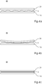
- the drive 38 of the screed bar 24 is selectively stimulated to a vibration which is superimposed on a kinematic movement in time with the sheet processing machine and causes the beam center first reaches the lowest point H 2 above the sheet 6 and shortly thereafter the ends of the screed 26 also occupy this position ( Figure 4a-c ).
- the timing is coordinated so that the first jump t 0 according to FIG. 5 a half period of the first natural frequency of the screed 24 takes place before the onset of the suction effect t 1 of the suction openings 41, so that the screed center reaches the bottom dead center H 2 of its oscillation in time with the onset of suction.
- the second jump then takes place, which also completely lowers the ends of the screed bar 24 and at the same time extinguishes the periodic natural vibration resulting from the first jump, so that the screed bar 24 remains at rest in the lower position H 2 at time t 2 means the screed reaches its dead center.
Description
Die Erfindung betrifft ein Verfahren und eine Vorrichtung zum Niederhalten eines Bogens auf dem Anlegetisch einer Bogen verarbeitenden Maschine, insbesondere Stanze oder Druckmaschine.The invention relates to a method and a device for holding down a sheet on the feed table of a sheet-processing machine, in particular punching or printing press.
Der Erfindung liegt das Problem zugrunde, dass Bogen, insbesondere dünne Bogen, dazu neigen, an ihrer Vorderkanten Verwölbungen oder Wellen auszubilden, die beim Weitertransport des Bogens durch nachgeordnete Greifersysteme zu Verspannungen oder Knitterbildung des Bogens an seiner Vorderkante führen können.The invention is based on the problem that sheets, in particular thin sheets, tend to form warping or waves on their leading edges, which can lead to tension or creasing of the sheet at its leading edge during further transport of the sheet by subordinate gripper systems.
Durch die
Die
Der Erfindung liegt die Aufgabe zugrunde ein alternatives Verfahren und eine Vorrichtung zu schaffen, bei welcher der Bogen nicht eingeklemmt wird.The invention has for its object to provide an alternative method and apparatus in which the sheet is not clamped.
Die Aufgabe wird erfindungsgemäß durch die Merkmale der Ansprüche 1 und 9 gelöst. Es ist ein besonderer Vorteil der Erfindung, dass ein vorgesehener Glättbalken den Bogen glättet ohne diesen zu klemmen. Durch diese Maßnahme wird sichergestellt, dass eine Oberfläche des Bogens nicht beschädigt wird. Durch eine spezielle Glättbewegung des Glättbalkens, nämlich von der Mitte zu den Seiten des Bogens wird der Bogen gleichmäßig zu den Seiten hin geglättet und somit eine Faltenbildung vermieden.The object is achieved by the features of
Zur Erzeugung der Glättbewegung des Glättbalkens ist ein im Takt der Bogen verarbeitenden Maschine antreibbarer, Kennlinien gesteuerter Antrieb, insbesondere ein Elektromotor vorgesehen.To generate the smoothing movement of the smoothing bar, a machine which can be driven in the cycle of the sheet and is provided with characteristic curves, especially an electric motor, is provided.
Ein vorgesehenes Viergelenkgetriebe verbindet den Antrieb mit dem Glättbalken.An intended four-bar linkage connects the drive to the screed bar.
Durch den erfindungsgemäßen Glättbalken können alle Grammaturen sicher verarbeitet werden ohne Markierungen auf dem Bogen zu hinterlassen, damit dieser faltenfrei von Greifeinrichtungen ergriffen werden kann.The smoothing bar according to the invention, all grammages can be safely processed without leaving marks on the sheet, so that it can be gripped wrinkle-free gripping devices.
Es ist ein besonderer Vorteil der Erfindung, dass alle Grammaturen sicher verarbeitet werden können ohne dass Markierungen auf dem Bogen entstehen. Unverspannte Bögen sichern in Druckmaschinen ein dublierfreies Druckergebnis und hohe PassergenauigkeitIt is a particular advantage of the invention that all grammages can be processed safely without causing marks on the sheet. Unstrained sheets ensure a duplication-free printing result and high register accuracy in printing presses
Ein Ausführungsbeispiel der Erfindung ist in den Zeichnungen dargestellt und wird im Folgenden beschrieben. Es zeigen
Figur 1- eine Stanze für bogenförmiges Material im Schnitt in schematischer Darstellung,
Figur 2- den erfindungsgemäßen Bogenniederhalter in einer Seitenansicht,
Figur 3- eine Vorderansicht des Niederhalters entgegen der Bogentransportrichtung gesehen,
- Figur 4a-c
- den Niederhalter in verschiedenen Positionen beim Glättvorgang,
Figur 5- ein Diagramm zur Ansteuerung des Elektromotors.
- FIG. 1
- a punch for sheet material in section in a schematic representation,
- FIG. 2
- the sheet metal blank according to the invention in a side view,
- FIG. 3
- seen a front view of the hold-down against the sheet transport direction,
- Figure 4a-c
- the hold-down in different positions during the smoothing process,
- FIG. 5
- a diagram for controlling the electric motor.
In
Die Bogen 6 werden durch einen Anleger 1 von einem Stapel vereinzelt, dem Bogentransportsystem 7 zugeführt und von an Greiferbrücken eines Greiferwagens 8 befestigten Greifern an ihrer Vorderkante ergriffen und in Bogentransportrichtung B intermittierend durch die verschiedenen Stationen 2, 3 und 4 der Stanz- und Prägemaschine 100 hindurchgezogen.
Das Bogentransportsystem 7 besitzt mehrere Greiferwagen 8, sodass mehrere Bogen 6 gleichzeitig in den verschiedenen Stationen 2, 3 und 4 bearbeitet werden können. Die Greiferwagen 8 können von einem Kettenantrieb oder in einer alternativen Ausführungsform durch einen elektromagnetischen Linearantrieb mit Wanderfeldmotoren angetrieben werden, wie beispielsweise in der
The
Die Stanzstation 2 besteht aus einem unteren Tiegel, einem sog. Untertisch 9, und einem oberen Tiegel, einem sog. Obertisch 10. Der Obertisch 10 ist vertikal hin- und herbewegbar gelagert und mit einem Oberwerkzeug 22 mit Stanz- und Rillmessern versehen. Der Untertisch 9 ist fest im Maschinengestell gelagert und mit einer Gegenplatte 18 zu den Stanz- und Rillmessern versehen. Alternativ kann auch der Obertisch 10 feststehend und der Untertisch 9 bewegt sein. Beim Prägen kommen an Stelle der Stanz- und Rillwerkzeuge Prägewerkzeuge, insbesondere in Form sogenannter Prägeklischees, zum Einsatz.The
Der Greiferwagen 8 transportiert den Bogen 6 von der Stanz- und Prägestation 2 in die nachfolgende Ausbrechstation 3, die mit Ausbrechwerkzeugen 19, 21 ausgestattet ist. In der Ausbrechstation 3 werden mit Hilfe der Ausbrechwerkzeuge 19, 21 die nicht benötigten Abfallstücke 11 aus dem Bogen 6 nach unten herausgestoßen, wodurch die Abfallstücke 11 in einen unter der Station eingeschobenen wagenartigen Behälter 12 fallen.The
Von der Ausbrechstation 3 gelangt der Bogen 6 in den Ausleger 4, wo der Bogen 6 entweder nur einfach abgelegt wird, oder aber gleichzeitig eine Trennung der einzelnen Nutzen eines jeweiligen Bogens 6 erfolgt. Dazu besitzt der Ausleger 4 ein Nutzentrennwerkzeug 19, 21. Der Ausleger 4 kann auch eine Palette 13 enthalten, auf der die einzelnen Bogen 6 bzw. Nutzen in Form eines Stapels 14 aufgestapelt werden, so dass nach Erreichen einer bestimmten Stapelhöhe die Palette 13 mit dem Bogenstapel 14 aus dem Bereich der Stanz- und Prägemaschine 100 weggefahren werden kann. Um die Maschine 100 während des Stapeltausches nicht anhalten zu müssen können Hilfsstapeleinrichtungen zum Einsatz kommen.From the
An einem den Stanz- und/oder prägestationen 2 bis 4 zugewandten Ende des Zuführtisches 16 ist ein Bogenniederhalter 23 angeordnet.At a the punching and / or embossing 2 to 4 facing the end of the feed table 16, a sheet hold-down 23 is arranged.
Der Niederhalter 23 weist im Wesentlichen einen quer zur Bogentransportrichtung über dem Zuführtisch 16 angeordneten Glättbalken 24 auf, welcher im Takt der Bogen verarbeitenden Maschine z. B. Bogendruckmaschine insbesondere Stanze aus einer Position H0 über dem Zuführtisch 16 in Richtung auf den Zuführtisch 16 in eine Position H2 absenkbar ist. Der Glättbalken 24 ist an seitlich des Zuführtisches 16 angeordneten Koppeln 26, 27 befestigt, welche jeweils Teil eines Viergelenkes 28, 29 sind. Jedes Viergelenk 28, 29 weist darüber hinaus zwei horizontal parallel zueinander angeordnete Lagerhebel 31, 32; 33, 34 auf. Diese sind mit einem ersten Ende stationär an einem Seitengestell des Zuführtisches 16 schwenkbar angeordnet und mit einem zweiten Ende jeweils an der Koppel 26; 27.The hold-
Die Koppel 26 weist einen dritten Hebel 36 auf, welcher mit seinem ersten Ende gelenkig an der Koppel 26 gelagert ist und mit seinem zweiten Ende mit einem Exzenter 37 verbunden ist, welcher von einem Motor 38 rotierend antreibbar ist. Der Motor 38 wird im Takt der Bogen verarbeitenden Maschine, z. B. Stanze 100 nach einem einstellbaren Geschwindigkeitsprofil 39 angetrieben.The
Das Geschwindigkeitsprofil 39 ist derart gestaltet, dass die Mitte des Glättbalkens 24 unmittelbar vor einem Erreichen der Endlage der Absenkbewegung H2 gerade so viel überschwingt (Überschwinger) dass die Mitte des Glättbalkens 24 ihre Endlage erreicht, bevor die Enden des Glättbalkens 24 ihre Endlage erreichen. Die Schwingung des Glättbalkens 24 klingt nach dem einmaligen Überschwingen der Balkenmitte ab oder wird ausgelöscht, so dass beim Einnehmen der Endposition der Enden des Glättbalkens 24 die Schwingung des Glättbalkens 24 nahezu vollständig ausgelöscht ist.The
Der Glättbalken 24 vollführt genau eine Schwingung des ersten Eigenfrequenz. Alternativ kann der Glättbalken 24 mehrere Perioden der Schwingung der ersten Eigenfrequenz vollführen.The smoothing
Der Glättbalken 24 wird vorzugsweise aus einer Ruhelage oder bei der Absenkbewegung mittels harmonischer Anregung zu der Schwingung der ersten Eigenfrequenz angeregt, welche durch Materialdämpfung oder gezielte Dämpfung über den Antrieb abklingt, während der Glättbalken 24 in seine Endlage H2 bewegt wird.The
Eine Überlagerung der Anregung mehrerer Eigenfrequenzen des Glättbalkens 24 wird durch eine von der ersten Eigenfrequenz abweichende Geometrie des Glättbalkens 24 bei einem ersten Kontakt des Glättbalkens 24 mit dem Bogen erreicht.A superposition of the excitation of a plurality of natural frequencies of the
Der Zuführtisch 16 weist unterhalb des Glättbalkens 24 eine Anzahl von Saugöffnungen 41 zur Fixierung eines Bogens 6 auf. Die Saugöffnungen 41 sind im Takt der Bogen verarbeitenden Maschine mit Saugluft eines Unterdruckerzeugers 42 beaufschlagbar und mittels einer Drossel 43 einstellbar.The feed table 16 has, below the
Ein über dem Zuführtisch 16 geförderter Bogen 6 wird an Vordermarken 44 ausgerichtet und angehalten. Sobald der Bogen 6 stoppt, wird der Glättbalken 24 nach unten bewegt. Zeitlich mit der Abwärtsbewegung des Glättbalkens 24, vorzugsweise an seinem Tiefpunkt H2 wird die Saugluft angeschaltet. Der Glättbalken 24 stellt somit sicher, dass ein Luftspalt unter dem Bogen 6 klein genug ist, dass die Saugöffnungen 41 den Bogen 6 sicher ansaugen können. Der Hub und somit der Mindestabstand des Spaltes zwischen der Totpunktlage H2 des Glättbalkens 24 und dem Zuführtisch 16 sind einstellbar, so dass unterschiedlich dicke Bögen 6 sicher angesaugt werden können.A conveyed over the feed table 16
Damit die Bogenansaugung faltenfrei erfolgt, weist der Glättbalken 24 eine schwingungsfähige Struktur auf, d. h. dieser biegt sich bei der Abwärtsbewegung merklich durch. Durch den Antrieb 38 wird der Glättbalken 24 gezielt zu einer Schwingung angeregt, die einer kinematischen Bewegung im Takt der Bogen verarbeitenden Maschine überlagert wird und die bewirkt, dass die Balkenmitte zuerst den tiefsten Punkt H2 über dem Bogen 6 erreicht und kurz darauf auch die Enden des Glättbalkens 26 ebenfalls diese Lage einnehmen (
Der zeitliche Ablauf ist so koordiniert, dass der erste Sprung t0 gemäß
Ergänzend wird vorgeschlagen, die Saugöffnungen 41 von der Mitte startend zu den Seiten mit Saugluft zu beaufschlagen, um einen Glattstreicheffekt zur Seite hin zu verbessern.In addition, it is proposed to apply the
- 11
- Anlegerinvestor
- 22
- Stanz- und/oder PrägestationPunching and / or embossing station
- 33
- Ausbrechstationstripping
- 44
- Ausleger, ggfs. mit NutzentrennstationOutrigger, if necessary with Nutzentrennstation
- 55
- Maschinengehäusemachine housing
- 66
- Bogenbow
- 77
- BogentransportsystemSheet transport system
- 88th
- Greiferwagen mit GreifernGripper carriage with grippers
- 99
- Untertisch / unterer TiegelLower table / lower crucible
- 1010
- Obertisch / oberer TiegelUpper table / upper crucible
- 1111
- Abfallstücketrimmings
- 1212
- Behältercontainer
- 1313
- Palettepalette
- 1414
- Auslagestapeldelivery pile
- 1515
- Steuerung mit Interface und EingabegerätenControl with interface and input devices
- 1616
- Zuführtisch mit einer Einheit zum Ausrichten der BogenFeed table with a unit for aligning the bow
- 1717
- Hauptantriebmain drive
- 1818
- Unterwerkzeuglower tool
- 1919
- Oberwerkzeug mit StempelnUpper tool with punches
- 2020
- ./../.
- 2121
- Nutzentrenngitter oder Ausbrechbrett (Unterwerkzeug)Dividing grille or stripping board (lower tool)
- 2222
- Oberwerkzeug (Stanzwerkzeug)Upper tool (punching tool)
- 2323
- NiederhalterStripper plate
- 2424
- Glättbalkenscreed
- 2525
- ./../.
- 2626
- Koppelpaddock
- 2727
- Koppelpaddock
- 2828
- Viergelenkfour joint
- 2929
- Viergelenkfour joint
- 3030
- ./../.
- 3131
- Lagerhebelbearing lever
- 3232
- Lagerhebelbearing lever
- 3333
- Lagerhebelbearing lever
- 3434
- Lagerhebelbearing lever
- 3535
- ./../.
- 3636
- Hebellever
- 3737
- Exzentereccentric
- 3838
- Motorengine
- 3939
- Geschwindigkeitsprofilvelocity profile
- 4040
- ./../.
- 4141
- Saugöffnungsuction opening
- 4242
- UnterdruckerzeugerVacuum generator
- 4343
- Drosselthrottle
- 4444
- Vordermarkenfront lays
- 4545
- ./../.
- 100100
- Flachbett-Bogenstanz- und/oder -prägemaschine (Stanzmaschine)Flatbed sheet punching and / or embossing machine (punching machine)
- BB
- BogentransportrichtungSheet transport direction
- Ee
- BogentransportebeneSheet transport plane
- toto
- Zeitpunkttime
- t1 t 1
- Zeitpunkttime
- t2 t 2
- Zeitpunkttime
- H0 H 0
- Höhe über ZuführtischHeight above feed table
- H1 H 1
- Höhe über ZuführtischHeight above feed table
- H2 H 2
- Höhe über ZuführtischHeight above feed table
Claims (12)
- Method for holding down a sheet on the feed table of a machine for processing sheets, the machine comprising a smoothing bar disposed above the feed table and lowerable in the direction of the feed table,
wherein the lowering movement of the smoothing bar (24) occurs in accordance with a predefinable velocity profile (39),
and wherein the smoothing bar (24) is caused to vibrate, said vibration superimposed to a kinematic movement in accordance with the cycle of the machine for processing sheets,
characterized in that
the velocity profile (39) is such that immediately before reaching the end position of the lowering movement (H2), the centre of the smoothing bar (24) overshoots just enough for the centre of the smoothing bar (24) to reach the end position before the ends of the smoothing bar reach their end positions. - Method according to claim 3,
characterized in
that the velocity profile (29) is such that after the overshooting of the centre of the bar, the vibration of the smoothing bar (24) fades or is eliminated so that when the end position of the bar ends is reached, the vibration of the smoothing bar is almost completely eliminated. - Method according to claim 2,
characterized in
that the smoothing bar (24) carries out precisely one vibration of the first natural frequency. - Method according to claim 2,
characterized in
that the smoothing bar (24) carries out multiple periods of the vibration of the first natural frequency. - Method according to claim 3,
characterized in
that the velocity profile (39) includes an actuation in which the smoothing bar (24) is accelerated from a rest position (H0) to a constant speed and is later decelerated to a speed equal to zero for the duration of an entire period of the first natural frequency of the smoothing bar (24). - Method according to claim 5,
characterized in
that a suction effect created by suction openings (41) that are provided is switched on as soon as the centre of the smoothing bar (24) has reached the height (H2). - Method according to claim 4,
characterized in
that in its rest position or on its downward path, the smoothing bar (24) is caused to vibrate in the first natural frequency by means of harmonic excitation, said vibration fading due to material damping or intentional damping by the drive while the smoothing bar (24) moves to its end position. - Method according to any one of the preceding claims,
characterized in
that a superimposition of the excitation of multiple natural frequencies of the smoothing bar (24) is achieved by a smoothing bar (24) geometry that deviates from the first natural mode when the smoothing bar (24) first contacts the sheet. - Device for holding down a sheet on the feed table of a machine for processing sheets, the machine comprising a smoothing bar disposed above the feed table and lowerable in the direction of the feed table,
wherein on both sides of the feed table (16), the smoothing bar (24) is supported for vertical movement in accordance with the cycle of the machine for processing sheets, and wherein a respective four bar linkage (26, 31, 32; 27, 33, 34) is provided to receive the smoothing bar (24),
characterized in
that an eccentric (37) is provided to drive the four bar linkage and a motor (38) controllable in accordance with characteristic lines is provided to drive the eccentric (37). - Device according to claim 9,
characterized in
that the feed table (16) has suction openings (41). - Device according to claim 10,
characterized in
that an adjustable vacuum is applicable to the suction openings (41) in accordance with the cycle of the machine for processing sheets. - Device according to any one of the preceding claims 9 to 11,
characterized in
that the machine for processing sheets is a diecutting machine or a printing machine.
Applications Claiming Priority (1)
| Application Number | Priority Date | Filing Date | Title |
|---|---|---|---|
| DE102014002468 | 2014-02-21 |
Publications (2)
| Publication Number | Publication Date |
|---|---|
| EP2923979A1 EP2923979A1 (en) | 2015-09-30 |
| EP2923979B1 true EP2923979B1 (en) | 2017-11-01 |
Family
ID=52464169
Family Applications (1)
| Application Number | Title | Priority Date | Filing Date |
|---|---|---|---|
| EP15153162.1A Active EP2923979B1 (en) | 2014-02-21 | 2015-01-30 | Method and device for holding down a sheet on the feed table of a sheet processing machine |
Country Status (5)
| Country | Link |
|---|---|
| US (1) | US9758331B2 (en) |
| EP (1) | EP2923979B1 (en) |
| JP (1) | JP6497963B2 (en) |
| CN (1) | CN104860092B (en) |
| DE (1) | DE102015201325A1 (en) |
Families Citing this family (4)
| Publication number | Priority date | Publication date | Assignee | Title |
|---|---|---|---|---|
| CN106696452B (en) * | 2017-01-03 | 2022-09-27 | 深圳市裕同包装科技股份有限公司 | Die cutting and coloring integrated equipment and processing method for die cutting and coloring paper |
| EP3461606B1 (en) * | 2017-10-02 | 2021-04-28 | Kama GmbH | Punch or embossing and sheet processing method |
| HRP20231738T1 (en) * | 2020-09-14 | 2024-03-15 | Gerhard Rauch Ges.m.b.H. | Device for embossing films |
| DE102021120371A1 (en) * | 2021-08-05 | 2023-02-09 | Multivac Sepp Haggenmüller Se & Co. Kg | PACKAGING MACHINE WITH FILM TRANSPORT DEVICE AND PROCESS |
Family Cites Families (18)
| Publication number | Priority date | Publication date | Assignee | Title |
|---|---|---|---|---|
| US4335954A (en) * | 1981-03-04 | 1982-06-22 | Xerox Corporation | Copier registration method and apparatus |
| DE3613969A1 (en) * | 1986-04-24 | 1987-10-29 | Heidelberger Druckmasch Ag | MONITORING DEVICE FOR THE SCORED SHEET FEEDER FOR PRINTING MACHINES |
| US4831419A (en) * | 1988-02-12 | 1989-05-16 | Xerox Corporation | Document handler vacuum belt platen transport clamping system |
| JPH04105969A (en) * | 1990-08-24 | 1992-04-07 | Canon Inc | Apparatus feeding sheet material |
| DE4028426C2 (en) | 1990-09-07 | 1998-04-16 | Kba Planeta Ag | Method and device for taking over a sheet aligned on a feed table of a sheet processing machine |
| JPH0790509B2 (en) * | 1990-11-07 | 1995-10-04 | 北越化成株式会社 | Continuous sheet striking device |
| US5202737A (en) * | 1992-06-12 | 1993-04-13 | Xerox Corporation | Method and apparatus for decurling sheets in a copying device |
| JPH0680271A (en) * | 1992-09-01 | 1994-03-22 | Eastman Kodak Japan Kk | Paper conveying device |
| JPH06191708A (en) * | 1992-12-25 | 1994-07-12 | Ricoh Co Ltd | Discharged-paper stacking apparatus for image recording device |
| US20030038420A1 (en) * | 2000-10-30 | 2003-02-27 | Vutek, Inc. | Printing system with vacuum table |
| DE10344402B4 (en) * | 2002-10-02 | 2007-09-20 | Man Roland Druckmaschinen Ag | Guide for sheet feeding on a printing machine |
| DE10246297B4 (en) * | 2002-10-02 | 2007-01-25 | Man Roland Druckmaschinen Ag | Hold-down device in the sheet system |
| DE102005001375A1 (en) * | 2005-01-12 | 2006-07-20 | Man Roland Druckmaschinen Ag | guide |
| DE202007012349U1 (en) | 2006-07-26 | 2007-12-13 | Heidelberger Druckmaschinen Ag | Sheet punching and embossing machine with register alignment |
| US7530567B2 (en) * | 2007-03-08 | 2009-05-12 | Xerox Corporation | Finisher compiler tray |
| EP2184165B1 (en) * | 2007-08-31 | 2012-12-05 | Komori Corporation | Sheet-fed printing press |
| JP2010131867A (en) * | 2008-12-04 | 2010-06-17 | Mitsubishi Heavy Ind Ltd | Device for holding down recording sheet and sheet printing machine |
| JP6304485B2 (en) * | 2014-02-25 | 2018-04-04 | セイコーエプソン株式会社 | Liquid ejection apparatus and medium flattening method |
-
2015
- 2015-01-27 DE DE102015201325.1A patent/DE102015201325A1/en not_active Withdrawn
- 2015-01-30 EP EP15153162.1A patent/EP2923979B1/en active Active
- 2015-02-16 CN CN201510086765.6A patent/CN104860092B/en active Active
- 2015-02-19 JP JP2015030580A patent/JP6497963B2/en active Active
- 2015-02-23 US US14/628,638 patent/US9758331B2/en active Active
Non-Patent Citations (1)
| Title |
|---|
| None * |
Also Published As
| Publication number | Publication date |
|---|---|
| JP6497963B2 (en) | 2019-04-10 |
| CN104860092A (en) | 2015-08-26 |
| US20150241875A1 (en) | 2015-08-27 |
| CN104860092B (en) | 2018-01-16 |
| DE102015201325A1 (en) | 2015-08-27 |
| EP2923979A1 (en) | 2015-09-30 |
| US9758331B2 (en) | 2017-09-12 |
| JP2015157354A (en) | 2015-09-03 |
Similar Documents
| Publication | Publication Date | Title |
|---|---|---|
| EP1882566B1 (en) | Sheet cutting and creasing press with registration alignment and method for operating such a press | |
| EP1944256B1 (en) | Device for aligning piles of sheets | |
| EP2452790B1 (en) | Processing station for a stamping machine and method for removing a test blank | |
| EP2407402B1 (en) | Method and device for positioning sheets | |
| EP2399715B1 (en) | Depositing and use separation station for a sheet blanking press | |
| DE102007020496A1 (en) | Sheet punching and embossing machine | |
| EP2923979B1 (en) | Method and device for holding down a sheet on the feed table of a sheet processing machine | |
| EP2397285B1 (en) | Stamping and/or embossing station of a sheet stamping machine | |
| EP2754541A2 (en) | Method for adjusting the pressing force a punching machine | |
| EP1970173A1 (en) | Sheet-fed punching and embossing press | |
| EP2087972B1 (en) | Device for punching | |
| DE102008011051A1 (en) | Sheet e.g. paper sheet, punching and embossing machine, has cam gear comprising cam disks, cam rollers and shafts, where driven cam disks roll on cam rollers that are fastened to movable platen | |
| EP2165954B1 (en) | Machine for processing sheets and method for delivering sheets | |
| EP2653420B1 (en) | Method for sheet transfer and punching machine with gripper transport system | |
| EP1935820A2 (en) | Sheet processing machine with sheet brake device and method for cleaning a sheet brake device | |
| DE102012019051A1 (en) | Transport apparatus i.e. feed table, for transporting sheet-shaped element e.g. paper, in sheet conveying plane, for feeding sheet to be processed in e.g. sheet printing machine, has actuator connected with blowing air chamber via gear box | |
| EP2762432B1 (en) | Monitoring method for preventing collisions of a stamping machine with brake brush | |
| EP2554345B1 (en) | Sheet stamping and/or embossing station with closing frame that is operated using compressed air | |
| EP2572843B1 (en) | Method for adjusting a stamping tool and sheet stamping station with covering panel that can be held using suction | |
| EP1882565A2 (en) | Method for punching and sheet cutting and creasing press | |
| EP1882659A2 (en) | Sheet-fed punching and embossing machine and method for sheet alignment | |
| DE102009058591A1 (en) | Sheet pressing and/or punching machine for punching of e.g. paper sheet utilized for packing product, has guide webs differentiated in curvature characteristics in area of punching station, pulling station and cantilever arm | |
| DE102011116220A1 (en) | Method for operating sheet punching machine for punching sheets used for packing e.g. cosmetics, involves controlling linear electromagnetic actuators during sheet transport process such that sheet is greatly accelerated | |
| EP2216278A2 (en) | Method for transferring sheets | |
| DE102013006348A1 (en) | Upper tool, processing station and method for breaking out |
Legal Events
| Date | Code | Title | Description |
|---|---|---|---|
| PUAI | Public reference made under article 153(3) epc to a published international application that has entered the european phase |
Free format text: ORIGINAL CODE: 0009012 |
|
| AK | Designated contracting states |
Kind code of ref document: A1 Designated state(s): AL AT BE BG CH CY CZ DE DK EE ES FI FR GB GR HR HU IE IS IT LI LT LU LV MC MK MT NL NO PL PT RO RS SE SI SK SM TR |
|
| AX | Request for extension of the european patent |
Extension state: BA ME |
|
| 17P | Request for examination filed |
Effective date: 20160330 |
|
| RBV | Designated contracting states (corrected) |
Designated state(s): AL AT BE BG CH CY CZ DE DK EE ES FI FR GB GR HR HU IE IS IT LI LT LU LV MC MK MT NL NO PL PT RO RS SE SI SK SM TR |
|
| GRAP | Despatch of communication of intention to grant a patent |
Free format text: ORIGINAL CODE: EPIDOSNIGR1 |
|
| INTG | Intention to grant announced |
Effective date: 20170601 |
|
| GRAS | Grant fee paid |
Free format text: ORIGINAL CODE: EPIDOSNIGR3 |
|
| GRAA | (expected) grant |
Free format text: ORIGINAL CODE: 0009210 |
|
| AK | Designated contracting states |
Kind code of ref document: B1 Designated state(s): AL AT BE BG CH CY CZ DE DK EE ES FI FR GB GR HR HU IE IS IT LI LT LU LV MC MK MT NL NO PL PT RO RS SE SI SK SM TR |
|
| REG | Reference to a national code |
Ref country code: GB Ref legal event code: FG4D Free format text: NOT ENGLISH |
|
| REG | Reference to a national code |
Ref country code: CH Ref legal event code: EP Ref country code: AT Ref legal event code: REF Ref document number: 941800 Country of ref document: AT Kind code of ref document: T Effective date: 20171115 |
|
| REG | Reference to a national code |
Ref country code: IE Ref legal event code: FG4D Free format text: LANGUAGE OF EP DOCUMENT: GERMAN |
|
| REG | Reference to a national code |
Ref country code: DE Ref legal event code: R096 Ref document number: 502015002214 Country of ref document: DE |
|
| REG | Reference to a national code |
Ref country code: NL Ref legal event code: MP Effective date: 20171101 |
|
| REG | Reference to a national code |
Ref country code: LT Ref legal event code: MG4D |
|
| PG25 | Lapsed in a contracting state [announced via postgrant information from national office to epo] |
Ref country code: NL Free format text: LAPSE BECAUSE OF FAILURE TO SUBMIT A TRANSLATION OF THE DESCRIPTION OR TO PAY THE FEE WITHIN THE PRESCRIBED TIME-LIMIT Effective date: 20171101 Ref country code: NO Free format text: LAPSE BECAUSE OF FAILURE TO SUBMIT A TRANSLATION OF THE DESCRIPTION OR TO PAY THE FEE WITHIN THE PRESCRIBED TIME-LIMIT Effective date: 20180201 Ref country code: SE Free format text: LAPSE BECAUSE OF FAILURE TO SUBMIT A TRANSLATION OF THE DESCRIPTION OR TO PAY THE FEE WITHIN THE PRESCRIBED TIME-LIMIT Effective date: 20171101 Ref country code: ES Free format text: LAPSE BECAUSE OF FAILURE TO SUBMIT A TRANSLATION OF THE DESCRIPTION OR TO PAY THE FEE WITHIN THE PRESCRIBED TIME-LIMIT Effective date: 20171101 Ref country code: LT Free format text: LAPSE BECAUSE OF FAILURE TO SUBMIT A TRANSLATION OF THE DESCRIPTION OR TO PAY THE FEE WITHIN THE PRESCRIBED TIME-LIMIT Effective date: 20171101 Ref country code: FI Free format text: LAPSE BECAUSE OF FAILURE TO SUBMIT A TRANSLATION OF THE DESCRIPTION OR TO PAY THE FEE WITHIN THE PRESCRIBED TIME-LIMIT Effective date: 20171101 |
|
| PG25 | Lapsed in a contracting state [announced via postgrant information from national office to epo] |
Ref country code: LV Free format text: LAPSE BECAUSE OF FAILURE TO SUBMIT A TRANSLATION OF THE DESCRIPTION OR TO PAY THE FEE WITHIN THE PRESCRIBED TIME-LIMIT Effective date: 20171101 Ref country code: HR Free format text: LAPSE BECAUSE OF FAILURE TO SUBMIT A TRANSLATION OF THE DESCRIPTION OR TO PAY THE FEE WITHIN THE PRESCRIBED TIME-LIMIT Effective date: 20171101 Ref country code: RS Free format text: LAPSE BECAUSE OF FAILURE TO SUBMIT A TRANSLATION OF THE DESCRIPTION OR TO PAY THE FEE WITHIN THE PRESCRIBED TIME-LIMIT Effective date: 20171101 Ref country code: IS Free format text: LAPSE BECAUSE OF FAILURE TO SUBMIT A TRANSLATION OF THE DESCRIPTION OR TO PAY THE FEE WITHIN THE PRESCRIBED TIME-LIMIT Effective date: 20180301 Ref country code: BG Free format text: LAPSE BECAUSE OF FAILURE TO SUBMIT A TRANSLATION OF THE DESCRIPTION OR TO PAY THE FEE WITHIN THE PRESCRIBED TIME-LIMIT Effective date: 20180201 Ref country code: GR Free format text: LAPSE BECAUSE OF FAILURE TO SUBMIT A TRANSLATION OF THE DESCRIPTION OR TO PAY THE FEE WITHIN THE PRESCRIBED TIME-LIMIT Effective date: 20180202 |
|
| PG25 | Lapsed in a contracting state [announced via postgrant information from national office to epo] |
Ref country code: DK Free format text: LAPSE BECAUSE OF FAILURE TO SUBMIT A TRANSLATION OF THE DESCRIPTION OR TO PAY THE FEE WITHIN THE PRESCRIBED TIME-LIMIT Effective date: 20171101 Ref country code: SK Free format text: LAPSE BECAUSE OF FAILURE TO SUBMIT A TRANSLATION OF THE DESCRIPTION OR TO PAY THE FEE WITHIN THE PRESCRIBED TIME-LIMIT Effective date: 20171101 Ref country code: CZ Free format text: LAPSE BECAUSE OF FAILURE TO SUBMIT A TRANSLATION OF THE DESCRIPTION OR TO PAY THE FEE WITHIN THE PRESCRIBED TIME-LIMIT Effective date: 20171101 Ref country code: CY Free format text: LAPSE BECAUSE OF FAILURE TO SUBMIT A TRANSLATION OF THE DESCRIPTION OR TO PAY THE FEE WITHIN THE PRESCRIBED TIME-LIMIT Effective date: 20171101 Ref country code: EE Free format text: LAPSE BECAUSE OF FAILURE TO SUBMIT A TRANSLATION OF THE DESCRIPTION OR TO PAY THE FEE WITHIN THE PRESCRIBED TIME-LIMIT Effective date: 20171101 |
|
| REG | Reference to a national code |
Ref country code: DE Ref legal event code: R097 Ref document number: 502015002214 Country of ref document: DE |
|
| PG25 | Lapsed in a contracting state [announced via postgrant information from national office to epo] |
Ref country code: PL Free format text: LAPSE BECAUSE OF FAILURE TO SUBMIT A TRANSLATION OF THE DESCRIPTION OR TO PAY THE FEE WITHIN THE PRESCRIBED TIME-LIMIT Effective date: 20171101 Ref country code: IT Free format text: LAPSE BECAUSE OF FAILURE TO SUBMIT A TRANSLATION OF THE DESCRIPTION OR TO PAY THE FEE WITHIN THE PRESCRIBED TIME-LIMIT Effective date: 20171101 Ref country code: RO Free format text: LAPSE BECAUSE OF FAILURE TO SUBMIT A TRANSLATION OF THE DESCRIPTION OR TO PAY THE FEE WITHIN THE PRESCRIBED TIME-LIMIT Effective date: 20171101 Ref country code: SM Free format text: LAPSE BECAUSE OF FAILURE TO SUBMIT A TRANSLATION OF THE DESCRIPTION OR TO PAY THE FEE WITHIN THE PRESCRIBED TIME-LIMIT Effective date: 20171101 |
|
| REG | Reference to a national code |
Ref country code: CH Ref legal event code: PL |
|
| PLBE | No opposition filed within time limit |
Free format text: ORIGINAL CODE: 0009261 |
|
| STAA | Information on the status of an ep patent application or granted ep patent |
Free format text: STATUS: NO OPPOSITION FILED WITHIN TIME LIMIT |
|
| PG25 | Lapsed in a contracting state [announced via postgrant information from national office to epo] |
Ref country code: MT Free format text: LAPSE BECAUSE OF FAILURE TO SUBMIT A TRANSLATION OF THE DESCRIPTION OR TO PAY THE FEE WITHIN THE PRESCRIBED TIME-LIMIT Effective date: 20171101 |
|
| 26N | No opposition filed |
Effective date: 20180802 |
|
| PG25 | Lapsed in a contracting state [announced via postgrant information from national office to epo] |
Ref country code: FR Free format text: LAPSE BECAUSE OF NON-PAYMENT OF DUE FEES Effective date: 20180131 Ref country code: LU Free format text: LAPSE BECAUSE OF NON-PAYMENT OF DUE FEES Effective date: 20180130 |
|
| REG | Reference to a national code |
Ref country code: IE Ref legal event code: MM4A |
|
| REG | Reference to a national code |
Ref country code: FR Ref legal event code: ST Effective date: 20180928 |
|
| REG | Reference to a national code |
Ref country code: BE Ref legal event code: MM Effective date: 20180131 |
|
| PG25 | Lapsed in a contracting state [announced via postgrant information from national office to epo] |
Ref country code: BE Free format text: LAPSE BECAUSE OF NON-PAYMENT OF DUE FEES Effective date: 20180131 Ref country code: SI Free format text: LAPSE BECAUSE OF FAILURE TO SUBMIT A TRANSLATION OF THE DESCRIPTION OR TO PAY THE FEE WITHIN THE PRESCRIBED TIME-LIMIT Effective date: 20171101 Ref country code: LI Free format text: LAPSE BECAUSE OF NON-PAYMENT OF DUE FEES Effective date: 20180131 Ref country code: CH Free format text: LAPSE BECAUSE OF NON-PAYMENT OF DUE FEES Effective date: 20180131 |
|
| PG25 | Lapsed in a contracting state [announced via postgrant information from national office to epo] |
Ref country code: IE Free format text: LAPSE BECAUSE OF NON-PAYMENT OF DUE FEES Effective date: 20180130 |
|
| PG25 | Lapsed in a contracting state [announced via postgrant information from national office to epo] |
Ref country code: MC Free format text: LAPSE BECAUSE OF FAILURE TO SUBMIT A TRANSLATION OF THE DESCRIPTION OR TO PAY THE FEE WITHIN THE PRESCRIBED TIME-LIMIT Effective date: 20171101 |
|
| GBPC | Gb: european patent ceased through non-payment of renewal fee |
Effective date: 20190130 |
|
| PG25 | Lapsed in a contracting state [announced via postgrant information from national office to epo] |
Ref country code: GB Free format text: LAPSE BECAUSE OF NON-PAYMENT OF DUE FEES Effective date: 20190130 |
|
| PG25 | Lapsed in a contracting state [announced via postgrant information from national office to epo] |
Ref country code: TR Free format text: LAPSE BECAUSE OF FAILURE TO SUBMIT A TRANSLATION OF THE DESCRIPTION OR TO PAY THE FEE WITHIN THE PRESCRIBED TIME-LIMIT Effective date: 20171101 |
|
| PG25 | Lapsed in a contracting state [announced via postgrant information from national office to epo] |
Ref country code: PT Free format text: LAPSE BECAUSE OF FAILURE TO SUBMIT A TRANSLATION OF THE DESCRIPTION OR TO PAY THE FEE WITHIN THE PRESCRIBED TIME-LIMIT Effective date: 20171101 |
|
| PG25 | Lapsed in a contracting state [announced via postgrant information from national office to epo] |
Ref country code: MK Free format text: LAPSE BECAUSE OF NON-PAYMENT OF DUE FEES Effective date: 20171101 Ref country code: HU Free format text: LAPSE BECAUSE OF FAILURE TO SUBMIT A TRANSLATION OF THE DESCRIPTION OR TO PAY THE FEE WITHIN THE PRESCRIBED TIME-LIMIT; INVALID AB INITIO Effective date: 20150130 |
|
| PG25 | Lapsed in a contracting state [announced via postgrant information from national office to epo] |
Ref country code: AL Free format text: LAPSE BECAUSE OF FAILURE TO SUBMIT A TRANSLATION OF THE DESCRIPTION OR TO PAY THE FEE WITHIN THE PRESCRIBED TIME-LIMIT Effective date: 20171101 |
|
| REG | Reference to a national code |
Ref country code: AT Ref legal event code: MM01 Ref document number: 941800 Country of ref document: AT Kind code of ref document: T Effective date: 20200130 |
|
| PG25 | Lapsed in a contracting state [announced via postgrant information from national office to epo] |
Ref country code: AT Free format text: LAPSE BECAUSE OF NON-PAYMENT OF DUE FEES Effective date: 20200130 |
|
| PGFP | Annual fee paid to national office [announced via postgrant information from national office to epo] |
Ref country code: DE Payment date: 20230131 Year of fee payment: 9 |
|
| P01 | Opt-out of the competence of the unified patent court (upc) registered |
Effective date: 20230427 |