EP2921101A1 - Endgerätevorrichtung und telemetriesystem - Google Patents
Endgerätevorrichtung und telemetriesystem Download PDFInfo
- Publication number
- EP2921101A1 EP2921101A1 EP15158954.6A EP15158954A EP2921101A1 EP 2921101 A1 EP2921101 A1 EP 2921101A1 EP 15158954 A EP15158954 A EP 15158954A EP 2921101 A1 EP2921101 A1 EP 2921101A1
- Authority
- EP
- European Patent Office
- Prior art keywords
- battery
- shutdown
- state
- terminal device
- information
- Prior art date
- Legal status (The legal status is an assumption and is not a legal conclusion. Google has not performed a legal analysis and makes no representation as to the accuracy of the status listed.)
- Granted
Links
Images


Classifications
-
- H—ELECTRICITY
- H04—ELECTRIC COMMUNICATION TECHNIQUE
- H04Q—SELECTING
- H04Q9/00—Arrangements in telecontrol or telemetry systems for selectively calling a substation from a main station, in which substation desired apparatus is selected for applying a control signal thereto or for obtaining measured values therefrom
-
- A—HUMAN NECESSITIES
- A61—MEDICAL OR VETERINARY SCIENCE; HYGIENE
- A61B—DIAGNOSIS; SURGERY; IDENTIFICATION
- A61B5/00—Measuring for diagnostic purposes; Identification of persons
- A61B5/0002—Remote monitoring of patients using telemetry, e.g. transmission of vital signals via a communication network
- A61B5/0015—Remote monitoring of patients using telemetry, e.g. transmission of vital signals via a communication network characterised by features of the telemetry system
-
- G—PHYSICS
- G06—COMPUTING OR CALCULATING; COUNTING
- G06F—ELECTRIC DIGITAL DATA PROCESSING
- G06F1/00—Details not covered by groups G06F3/00 - G06F13/00 and G06F21/00
- G06F1/26—Power supply means, e.g. regulation thereof
- G06F1/28—Supervision thereof, e.g. detecting power-supply failure by out of limits supervision
-
- A—HUMAN NECESSITIES
- A61—MEDICAL OR VETERINARY SCIENCE; HYGIENE
- A61B—DIAGNOSIS; SURGERY; IDENTIFICATION
- A61B2560/00—Constructional details of operational features of apparatus; Accessories for medical measuring apparatus
- A61B2560/02—Operational features
- A61B2560/0204—Operational features of power management
-
- A—HUMAN NECESSITIES
- A61—MEDICAL OR VETERINARY SCIENCE; HYGIENE
- A61B—DIAGNOSIS; SURGERY; IDENTIFICATION
- A61B5/00—Measuring for diagnostic purposes; Identification of persons
- A61B5/0002—Remote monitoring of patients using telemetry, e.g. transmission of vital signals via a communication network
Definitions
- the present invention relates to a terminal device and a telemetry system.
- JP-A-5-192304 discloses a telemetry system in which a biological information display device on the receiving side monitors the radio wave state of a terminal device performing transmission, and an alarm generates based on a result of the monitoring.
- JP-A-5-192304 discloses also that, in the case where a nurse turns off a power switch of a transmitter, a prediction signal is transmitted to a receiver. When the radio wave is stopped at the receiver after the arrival of the prediction signal, it is determined that the shutdown of the transmitter is caused by regular operation, and the alarm is stopped.
- JP-A-2001-188497 discloses that notifications of battery exhaustion, battery detachment, and recovery to the normal voltage when a battery is reattached are performed by using a display device having a memory property.
- An object of the invention is to provide a terminal device and telemetry system in which a situation where a shutdown state of a battery occurs in the terminal device can be surely determined in a biological information display device that is on the reception side.
- a terminal device in which a transmitter transmits biological information and battery state information to a biological information display device includes a shutdown detection unit that detects a shutdown state of a battery and a transmission control unit that, when the shutdown detection unit detects the battery shutdown state, causes the transmitter to transmit the battery state information indicative of shutdown.
- the biological information display device that is on the reception side can determine a situation where a battery shutdown state occurs in the terminal device. Since at least one of turn off due to operation of the power switch, and detachment of the battery is detected, it is possible to identify whether the battery shutdown state is caused by at least one of turn off due to operation of the power switch and detachment of the battery.
- Fig. 1 is a diagram of an embodiment of the telemetry system of the invention.
- the telemetry system can include a plurality of terminal devices 301 to 30n which collect and transmit biological information, such as telemeters, and a biological information display device 10 which receives and displays the biological information transmitted from the terminal devices 301 to 30n, such as central monitors.
- a plurality of biological information display devices 10 may be disposed.
- each of the terminal devices 301 to 30n may be configured as shown in Fig. 2 .
- a controller 20 configured by, for example, a computer controls components of each device.
- a plurality of sensors 21 to 23 are connected to the controller 20.
- the sensors 21 to 23 measure biological signals such as an electrocardiogram, the blood pressure, brain waves, and the body temperature.
- the numbers of the sensors in the respective terminal devices 301 to 30n may be different from or equal to one another.
- a transmitter 24 is connected to the controller 20.
- the biological signals obtained from the sensors 21 to 23 are transmitted from the transmitter 24.
- a display section 25 for displaying the operation status of the device and the like is connected to the controller 20.
- Each of the terminal devices 301 to 30n operates by power of a battery 26.
- a remaining charge amount detection unit 27 is disposed in order to detect the remaining charge amount of the battery 26. Information of the remaining charge amount obtained by the remaining charge amount detection unit 27 is fetched by the controller 20, and then transmitted from the transmitter 24.
- a power switch 28 is disposed in each of the terminal devices 301 to 30n. On/off operations of the power switch 28 are detected by a switch operation detection unit 29. On/off information of the power switch 28 detected by the switch operation detection unit 29 is sent to the controller 20.
- the controller 20 includes a power supply control unit 51.
- the power supply control unit 51 receives the on/off information of the power switch 28, and performs controls related to a power supply.
- the power supply control unit 51 Upon reception of the on information of the power switch 28, the power supply control unit 51 immediately starts a power supply from the battery 26 to the components. By contrast, when the power supply control unit 51 receives the off information of the power switch 28, the power supply control unit 51 stops supplying the power supply from the battery 26 to the components after elapse of a predetermined time period.
- the controller 20 which is the transmission control unit transmits power off information from the transmitter 24 during the predetermined time period.
- a battery detection unit 52 is disposed in each of the terminal devices 301 to 30n.
- the battery detection unit 52 can be realized by a configuration where a switch or sensor for detecting a battery is disposed in a battery box.
- the unit detects a state where the battery 26 is detached from the battery box (hereinafter, the state is referred to as the battery detachment state), and notifies the controller 20 of the state.
- the controller 20 which is the transmission control unit transmits the battery detachment information from the transmitter 24.
- Each of the terminal devices 301 to 30n may include an another battery for detecting a state of the switch or sensor and transmitting the battery detachment state.
- the on/off information of the power switch 28 and the battery detachment state indicate the battery shutdown state
- the switch operation detection unit 29 and the battery detection unit 52 constitute the shutdown detection unit for detecting the shutdown state of the battery.
- the switch operation detection unit 29 and the battery detection unit 52 are disposed in the embodiment, only one of these units may be disposed.
- the biological information display device 10 can include a central controller 11 configured by, for example, a computer.
- a display section 12, a receiver 13, and an input section 14 are connected to the central controller 11.
- the display section 12 displays biological information and the like.
- the receiver 13 is used for receiving the biological information transmitted from the terminal devices 301 to 30n, and the like.
- the input section 14 can include a touch panel, a keyboard, a mouse, or the like, and is used for inputting a command and an operation on the screen.
- the central controller 11 can include a radio wave state detection unit 41 and a display control unit 42.
- the radio wave state detection unit 41 detects the states (for example, electric field strengths) of radio waves transmitted from the terminal devices 301 to 30n.
- the display control unit 42 can perform a display indicating shutdown of the battery.
- the display control unit 42 may divide the screen of the display section 12 into a plurality of display regions, and display sets of biological information transmitted from the terminal devices 301 to 30n in the respective corresponding display regions.
- a unit for generating an alarm sound may be disposed in the biological information display device 10.
- Fig. 3 illustrates an example of a display screen in which one screen is divided into regions in accordance with the plurality of terminal devices, and displays respectively relating to sets of information of the terminal devices are performed on the divided display regions.
- the whole screen is divided into eight regions in accordance with eight terminal devices to form eight display regions.
- a sub display region 83 a patient ID or a bed number is displayed in the upper portion, and a channel number is displayed in the lower portion.
- a battery remaining charge amount icon 85 is displayed in a sub display region on the right side of the sub display region 83.
- As the battery remaining charge amount icon 85 three rectangular segments having a trapezoidal or parallelogram shape are displayed at the maximum in the longitudinal direction in a frame having a shape of a dry cell. The lower the remaining charge amount, the smaller number of segments is displayed.
- An antenna icon 84 indicating the reception condition is displayed in a region on the right side of the region where the battery remaining charge amount icon 85 is displayed.
- an antenna bar display of the antenna icon 84 is displayed while changing to one of four states in accordance with the reception condition. As the reception condition becomes worse, the number of bars which are displayed in proximity to the right side of the antenna figure display at the leftmost position is further reduced.
- An alarm battery remaining charge amount icon 87 in which a battery icon indicating that the battery has no remaining charge amount and empty is enlargedly shown is displayed in a sub display region 86 below the region on the left side of the sub display region 83.
- a sub display region 88 is a display region for displaying biological information, and a signal waveform or the like is displayed in the region.
- a sub display region 89 is a display region for displaying message characters, and "Battery replacement" which are message characters for prompting battery replacement, "Radio wave interruption” which are message characters indicating interruption of the radio wave, and like are displayed in the region.
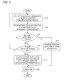
- the terminal devices 301 to 30n operate in accordance with the program shown in Fig. 4 .
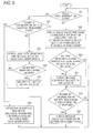
- the central controller 11 of the biological information display device 10 executes a program corresponding to the flowchart shown in Fig. 5 , for example, the controller 11 functions as the radio wave state detection unit 41 and the display control unit 42.
- the operation will be described with reference to the flowchart.
- the flowchart of Fig. 5 illustrates the operation corresponding to one terminal device.
- the power switch 28 is turned on, and the operation is started to collect biological information and detect the battery remaining charge amount (S11). Then, the collected biological information and the information of the battery remaining charge amount are transmitted to the biological information display device 10 (S12). Moreover, it is detected whether the device is in the battery detachment state or not (S13). If the device is in the battery detachment state, battery detachment state information is transmitted to the biological information display device 10 (S17), and the device is powered off by detachment of the battery (S16).
- step S13 If in step S13 the process branches to NO, it is detected whether the power switch 28 is turned off or not (S14). If the power switch 28 is turned off, the power supply is maintained for the predetermined time period, the turn off information of the power switch 28 is transmitted (S15), and the device is powered off after elapse of the predetermined time period (S16).
- the power is turned on, and the controller is started to operate as the radio wave state detection unit 41 and detect whether the radio wave interruption state exists or not (S21). If the process branches to NO, signal waveforms and the like are displayed based on the biological information sent from the terminal devices 301 to 30n, and the display of the remaining charge amount is output based on the information of the battery remaining charge amount (S22).
- Fig. 6 illustrates an example of the display.
- step S23 it is detected whether the battery remaining charge amount is at a level where the battery must be replaced or not, based on the battery remaining charge amount information (S23). If the amount is at the level where the battery must be replaced, a message for prompting battery replacement is displayed in the sub display region 89 (S24). After step S24, or if in step S23 the process branches to NO, it is detected whether the power off information or the battery detachment state information is received or not (S25). If in step S25 the process branches to YES, a message indicating the power off or the battery detachment state is displayed in the sub display region 89, based on information sent from the terminal devices 301 to 30n (S26). Fig.
- FIG. 7A illustrates an example in which a message indicating the power off is displayed in the sub display region 89
- Fig. 7B illustrates an example in which a message indicating the battery detachment state is displayed in the sub display region 89.
- step S25 If in step S25 the process branches to NO, by contrast, the process returns to step S21 to be continued. If in step S21 the process branches to YES, it is detected whether the power is turned off or the device is in the battery detachment state (S27). If in step S27 the process branches to YES, the display in the sub display region for biological information is not performed, and a message indicating the radio wave interruption is displayed as shown in Fig. 8 (S28).
- step S27 If in step S27 the process branches to NO, a saw-tooth waveform and a message indicating the radio wave interruption are displayed as shown in Fig. 9 (S29).
- step S29 an audible alarm may be generated.
- step S30 it is determined whether a state where the battery has no remaining charge amount is produced or not (S30). If it is determined that the battery has no remaining charge amount, a no-battery icon is enlargedly displayed in the sub display region 86 as shown in Fig. 10 (S31). In step S31, an escalation alarm in which the volume of the audible alarm is increased may be generated. If in step S30 the process branches to NO, the display of the saw-tooth waveform and message indicating the radio wave interruption which have been displayed in step S29 is maintained.
- the cause of the shutdown or the like is displayed before the radio wave interruption occurs ( Fig. 7 ), and, after the radio wave interruption, the display ( Fig. 8 ) is performed which is different from displays ( Fig. 9 ) performed in the case where the terminal devices 301 to 30n leave the communication range, and where the reception condition is deteriorated.
- the radio wave interruption is caused by the power off due to an operation performed by the medical person, or the battery detachment state, and hence it is not required to take unnecessary countermeasures such as that a patient who may leave the communication range is searched, and that the terminal devices 301 to 30n are checked for abnormalities.
- the display In a case such as that it is forgotten to turn on the power or attach a battery, the display is different from displays performed in the case of out of communication range and deterioration of the reception condition, and it is possible to check also forgetting of turning on of the power and attachment of a battery.
- a shutdown state of a battery is detected based on the power off information or the battery detachment state information.
- the biological information display device 10 may further include a determination unit which obtains information of the remaining charge amount of the battery from the terminal devices 301 to 30n, and which, in combination of the information and the radio wave state, determines shutdown of the battery. In the case where the remaining charge amount of the battery is sufficient, when the radio wave interruption suddenly occurs, for example, it is determined that a battery shutdown state occurs, and the display which is different from displays performed in the case of out of communication range and deterioration of the reception condition can be performed.
Landscapes
- Engineering & Computer Science (AREA)
- Health & Medical Sciences (AREA)
- Life Sciences & Earth Sciences (AREA)
- Computer Networks & Wireless Communication (AREA)
- Physics & Mathematics (AREA)
- Theoretical Computer Science (AREA)
- Molecular Biology (AREA)
- General Health & Medical Sciences (AREA)
- Heart & Thoracic Surgery (AREA)
- Medical Informatics (AREA)
- Pathology (AREA)
- Surgery (AREA)
- Animal Behavior & Ethology (AREA)
- Biomedical Technology (AREA)
- Public Health (AREA)
- Veterinary Medicine (AREA)
- Biophysics (AREA)
- General Physics & Mathematics (AREA)
- General Engineering & Computer Science (AREA)
- Measuring And Recording Apparatus For Diagnosis (AREA)
- Arrangements For Transmission Of Measured Signals (AREA)
Applications Claiming Priority (2)
| Application Number | Priority Date | Filing Date | Title |
|---|---|---|---|
| JP2014058551 | 2014-03-20 | ||
| JP2014071640A JP6457188B2 (ja) | 2014-03-20 | 2014-03-31 | 端末装置及びテレメトリーシステム |
Publications (2)
| Publication Number | Publication Date |
|---|---|
| EP2921101A1 true EP2921101A1 (de) | 2015-09-23 |
| EP2921101B1 EP2921101B1 (de) | 2019-07-31 |
Family
ID=52784902
Family Applications (1)
| Application Number | Title | Priority Date | Filing Date |
|---|---|---|---|
| EP15158954.6A Active EP2921101B1 (de) | 2014-03-20 | 2015-03-13 | Endgerätevorrichtung und telemetriesystem |
Country Status (4)
| Country | Link |
|---|---|
| US (1) | US9762977B2 (de) |
| EP (1) | EP2921101B1 (de) |
| JP (1) | JP6457188B2 (de) |
| CN (1) | CN104933844B (de) |
Families Citing this family (4)
| Publication number | Priority date | Publication date | Assignee | Title |
|---|---|---|---|---|
| JP6708195B2 (ja) * | 2017-10-26 | 2020-06-10 | 株式会社デンソー | 通信装置 |
| JP7211016B2 (ja) * | 2018-11-02 | 2023-01-24 | 株式会社デンソー | 通報表示装置および車両管理システム |
| CN112540262A (zh) * | 2020-11-18 | 2021-03-23 | 广西电网有限责任公司电力科学研究院 | 电压时间型馈线自动化测试系统及其测试方法 |
| US20230301640A1 (en) * | 2022-03-23 | 2023-09-28 | Insurgical, Inc. | Mechanism to wake a battery in a surgical device |
Citations (5)
| Publication number | Priority date | Publication date | Assignee | Title |
|---|---|---|---|---|
| DE1805444A1 (de) * | 1968-10-26 | 1970-05-14 | Bosch Elektronik Gmbh | Einrichtung zur drahtgebundenen oder drahtlosen UEbertragung von elektrischen Messwerten |
| JPH05192304A (ja) | 1992-01-23 | 1993-08-03 | Nippon Koden Corp | 医用テレメータ |
| JP2001188497A (ja) | 1999-12-27 | 2001-07-10 | Fuji Xerox Co Ltd | 表示装置 |
| US6376931B1 (en) * | 1998-11-30 | 2002-04-23 | Samsung Electronics Co., Ltd. | Portable computer having power supply system performed by detachment of battery pack |
| GB2425180A (en) * | 2005-04-14 | 2006-10-18 | Justin Pisani | Wearable physiological monitor with wireless transmitter |
Family Cites Families (12)
| Publication number | Priority date | Publication date | Assignee | Title |
|---|---|---|---|---|
| JPH05192300A (ja) * | 1992-01-22 | 1993-08-03 | Terumo Corp | 携帯型医療装置 |
| JP3668923B2 (ja) * | 1998-03-02 | 2005-07-06 | 日本光電工業株式会社 | 医用テレメータシステム |
| US20010027384A1 (en) * | 2000-03-01 | 2001-10-04 | Schulze Arthur E. | Wireless internet bio-telemetry monitoring system and method |
| EP3539463A1 (de) | 2005-04-14 | 2019-09-18 | Hidalgo Limited | Überwachungsvorrichtung und -system |
| JP2008194358A (ja) * | 2007-02-15 | 2008-08-28 | Matsushita Electric Ind Co Ltd | 健康診断ネットワークシステム、制御方法、及びプログラム |
| CN201139561Y (zh) * | 2007-11-16 | 2008-10-29 | 陆尧胜 | 无线宫压监护装置 |
| RU2499550C2 (ru) * | 2008-03-10 | 2013-11-27 | Конинклейке Филипс Электроникс Н.В. | Система контроля экг с конфигурируемыми пределами включения сигналов тревоги |
| TW201106301A (en) * | 2009-08-13 | 2011-02-16 | Singli Technology Inc | Anti-error monitoring method of care system for bedridden persons |
| JP5432817B2 (ja) * | 2010-05-20 | 2014-03-05 | パナソニック株式会社 | 車両盗難警報音駆動回路 |
| JP5587810B2 (ja) | 2010-06-01 | 2014-09-10 | 日本光電工業株式会社 | 患者位置表示システム |
| JP5661563B2 (ja) * | 2010-09-21 | 2015-01-28 | 日本光電工業株式会社 | 医用テレメータシステムおよび医用テレメータ |
| CN102499662A (zh) * | 2011-10-12 | 2012-06-20 | 深圳市赢时通电子有限公司 | 婴幼儿远程监测的方法、系统、传感器及监测器 |
-
2014
- 2014-03-31 JP JP2014071640A patent/JP6457188B2/ja active Active
-
2015
- 2015-03-11 US US14/644,890 patent/US9762977B2/en active Active
- 2015-03-13 EP EP15158954.6A patent/EP2921101B1/de active Active
- 2015-03-13 CN CN201510112442.XA patent/CN104933844B/zh active Active
Patent Citations (5)
| Publication number | Priority date | Publication date | Assignee | Title |
|---|---|---|---|---|
| DE1805444A1 (de) * | 1968-10-26 | 1970-05-14 | Bosch Elektronik Gmbh | Einrichtung zur drahtgebundenen oder drahtlosen UEbertragung von elektrischen Messwerten |
| JPH05192304A (ja) | 1992-01-23 | 1993-08-03 | Nippon Koden Corp | 医用テレメータ |
| US6376931B1 (en) * | 1998-11-30 | 2002-04-23 | Samsung Electronics Co., Ltd. | Portable computer having power supply system performed by detachment of battery pack |
| JP2001188497A (ja) | 1999-12-27 | 2001-07-10 | Fuji Xerox Co Ltd | 表示装置 |
| GB2425180A (en) * | 2005-04-14 | 2006-10-18 | Justin Pisani | Wearable physiological monitor with wireless transmitter |
Also Published As
| Publication number | Publication date |
|---|---|
| JP6457188B2 (ja) | 2019-01-23 |
| US20150271574A1 (en) | 2015-09-24 |
| EP2921101B1 (de) | 2019-07-31 |
| JP2015192720A (ja) | 2015-11-05 |
| CN104933844B (zh) | 2019-10-15 |
| CN104933844A (zh) | 2015-09-23 |
| US9762977B2 (en) | 2017-09-12 |
Similar Documents
| Publication | Publication Date | Title |
|---|---|---|
| US9019098B2 (en) | Wireless communication system | |
| EP2921101B1 (de) | Endgerätevorrichtung und telemetriesystem | |
| US8843072B2 (en) | Sensing wireless terminal | |
| JP2011098189A (ja) | 生体情報モニタ装置 | |
| EP2627103B1 (de) | Drahtlose kommunikationsvorrichtung und drahtloses kommunikationssystem | |
| GB2604808A (en) | Apparatus and method for controlling a system of resources | |
| KR20070064980A (ko) | 디스플레이 장치 | |
| US12523704B2 (en) | Lead-acid battery monitoring apparatus and lead-acid battery monitoring method | |
| JP2012130692A (ja) | 表示された情報の遅延を回避しながら送信機の電力消費を減らすための方法およびシステム | |
| US10133340B2 (en) | Biological information monitoring system | |
| JP2012095042A (ja) | 電子制御装置 | |
| CN108120496B (zh) | 移动式操作板 | |
| US10839668B2 (en) | Alarm information processing apparatus and control program for alarm information processing apparatus | |
| US10485519B2 (en) | Ultrasonic diagnostic apparatus, biological signal acquisition apparatus and method for controlling ultrasonic diagnostic apparatus | |
| JP7045832B2 (ja) | 生体情報測定装置 | |
| CN103040442A (zh) | 腕式无线监护装置 | |
| KR101505122B1 (ko) | 원격 관리형 자동제세동기 및 그 제어방법 | |
| JP6069131B2 (ja) | 受信装置及び生体情報収集システム | |
| JP7387252B2 (ja) | 信号中継装置、および生体情報モニタリングシステム | |
| US12518616B2 (en) | Physiological alarm control system and method | |
| JP6258413B2 (ja) | 脳波監視システム | |
| JP7222616B2 (ja) | センサ、および生体情報監視システム | |
| JP2010005127A (ja) | 生体情報測定システム及び生体情報受信装置 | |
| JPH04186450A (ja) | 情報処理装置 | |
| CN101859471A (zh) | 便携式病人看护报警器 |
Legal Events
| Date | Code | Title | Description |
|---|---|---|---|
| PUAI | Public reference made under article 153(3) epc to a published international application that has entered the european phase |
Free format text: ORIGINAL CODE: 0009012 |
|
| AK | Designated contracting states |
Kind code of ref document: A1 Designated state(s): AL AT BE BG CH CY CZ DE DK EE ES FI FR GB GR HR HU IE IS IT LI LT LU LV MC MK MT NL NO PL PT RO RS SE SI SK SM TR |
|
| AX | Request for extension of the european patent |
Extension state: BA ME |
|
| 17P | Request for examination filed |
Effective date: 20160323 |
|
| RBV | Designated contracting states (corrected) |
Designated state(s): AL AT BE BG CH CY CZ DE DK EE ES FI FR GB GR HR HU IE IS IT LI LT LU LV MC MK MT NL NO PL PT RO RS SE SI SK SM TR |
|
| GRAP | Despatch of communication of intention to grant a patent |
Free format text: ORIGINAL CODE: EPIDOSNIGR1 |
|
| STAA | Information on the status of an ep patent application or granted ep patent |
Free format text: STATUS: GRANT OF PATENT IS INTENDED |
|
| INTG | Intention to grant announced |
Effective date: 20181207 |
|
| RAP1 | Party data changed (applicant data changed or rights of an application transferred) |
Owner name: NIHON KOHDEN CORPORATION |
|
| GRAJ | Information related to disapproval of communication of intention to grant by the applicant or resumption of examination proceedings by the epo deleted |
Free format text: ORIGINAL CODE: EPIDOSDIGR1 |
|
| STAA | Information on the status of an ep patent application or granted ep patent |
Free format text: STATUS: REQUEST FOR EXAMINATION WAS MADE |
|
| GRAP | Despatch of communication of intention to grant a patent |
Free format text: ORIGINAL CODE: EPIDOSNIGR1 |
|
| STAA | Information on the status of an ep patent application or granted ep patent |
Free format text: STATUS: GRANT OF PATENT IS INTENDED |
|
| INTC | Intention to grant announced (deleted) | ||
| INTG | Intention to grant announced |
Effective date: 20190409 |
|
| GRAS | Grant fee paid |
Free format text: ORIGINAL CODE: EPIDOSNIGR3 |
|
| GRAA | (expected) grant |
Free format text: ORIGINAL CODE: 0009210 |
|
| STAA | Information on the status of an ep patent application or granted ep patent |
Free format text: STATUS: THE PATENT HAS BEEN GRANTED |
|
| AK | Designated contracting states |
Kind code of ref document: B1 Designated state(s): AL AT BE BG CH CY CZ DE DK EE ES FI FR GB GR HR HU IE IS IT LI LT LU LV MC MK MT NL NO PL PT RO RS SE SI SK SM TR |
|
| REG | Reference to a national code |
Ref country code: CH Ref legal event code: EP Ref country code: GB Ref legal event code: FG4D |
|
| REG | Reference to a national code |
Ref country code: AT Ref legal event code: REF Ref document number: 1160044 Country of ref document: AT Kind code of ref document: T Effective date: 20190815 |
|
| REG | Reference to a national code |
Ref country code: IE Ref legal event code: FG4D |
|
| REG | Reference to a national code |
Ref country code: DE Ref legal event code: R096 Ref document number: 602015034641 Country of ref document: DE |
|
| REG | Reference to a national code |
Ref country code: NL Ref legal event code: MP Effective date: 20190731 |
|
| REG | Reference to a national code |
Ref country code: LT Ref legal event code: MG4D |
|
| REG | Reference to a national code |
Ref country code: AT Ref legal event code: MK05 Ref document number: 1160044 Country of ref document: AT Kind code of ref document: T Effective date: 20190731 |
|
| PG25 | Lapsed in a contracting state [announced via postgrant information from national office to epo] |
Ref country code: FI Free format text: LAPSE BECAUSE OF FAILURE TO SUBMIT A TRANSLATION OF THE DESCRIPTION OR TO PAY THE FEE WITHIN THE PRESCRIBED TIME-LIMIT Effective date: 20190731 Ref country code: NO Free format text: LAPSE BECAUSE OF FAILURE TO SUBMIT A TRANSLATION OF THE DESCRIPTION OR TO PAY THE FEE WITHIN THE PRESCRIBED TIME-LIMIT Effective date: 20191031 Ref country code: PT Free format text: LAPSE BECAUSE OF FAILURE TO SUBMIT A TRANSLATION OF THE DESCRIPTION OR TO PAY THE FEE WITHIN THE PRESCRIBED TIME-LIMIT Effective date: 20191202 Ref country code: AT Free format text: LAPSE BECAUSE OF FAILURE TO SUBMIT A TRANSLATION OF THE DESCRIPTION OR TO PAY THE FEE WITHIN THE PRESCRIBED TIME-LIMIT Effective date: 20190731 Ref country code: NL Free format text: LAPSE BECAUSE OF FAILURE TO SUBMIT A TRANSLATION OF THE DESCRIPTION OR TO PAY THE FEE WITHIN THE PRESCRIBED TIME-LIMIT Effective date: 20190731 Ref country code: SE Free format text: LAPSE BECAUSE OF FAILURE TO SUBMIT A TRANSLATION OF THE DESCRIPTION OR TO PAY THE FEE WITHIN THE PRESCRIBED TIME-LIMIT Effective date: 20190731 Ref country code: BG Free format text: LAPSE BECAUSE OF FAILURE TO SUBMIT A TRANSLATION OF THE DESCRIPTION OR TO PAY THE FEE WITHIN THE PRESCRIBED TIME-LIMIT Effective date: 20191031 Ref country code: LT Free format text: LAPSE BECAUSE OF FAILURE TO SUBMIT A TRANSLATION OF THE DESCRIPTION OR TO PAY THE FEE WITHIN THE PRESCRIBED TIME-LIMIT Effective date: 20190731 Ref country code: HR Free format text: LAPSE BECAUSE OF FAILURE TO SUBMIT A TRANSLATION OF THE DESCRIPTION OR TO PAY THE FEE WITHIN THE PRESCRIBED TIME-LIMIT Effective date: 20190731 |
|
| PG25 | Lapsed in a contracting state [announced via postgrant information from national office to epo] |
Ref country code: IS Free format text: LAPSE BECAUSE OF FAILURE TO SUBMIT A TRANSLATION OF THE DESCRIPTION OR TO PAY THE FEE WITHIN THE PRESCRIBED TIME-LIMIT Effective date: 20191130 Ref country code: AL Free format text: LAPSE BECAUSE OF FAILURE TO SUBMIT A TRANSLATION OF THE DESCRIPTION OR TO PAY THE FEE WITHIN THE PRESCRIBED TIME-LIMIT Effective date: 20190731 Ref country code: RS Free format text: LAPSE BECAUSE OF FAILURE TO SUBMIT A TRANSLATION OF THE DESCRIPTION OR TO PAY THE FEE WITHIN THE PRESCRIBED TIME-LIMIT Effective date: 20190731 Ref country code: LV Free format text: LAPSE BECAUSE OF FAILURE TO SUBMIT A TRANSLATION OF THE DESCRIPTION OR TO PAY THE FEE WITHIN THE PRESCRIBED TIME-LIMIT Effective date: 20190731 Ref country code: GR Free format text: LAPSE BECAUSE OF FAILURE TO SUBMIT A TRANSLATION OF THE DESCRIPTION OR TO PAY THE FEE WITHIN THE PRESCRIBED TIME-LIMIT Effective date: 20191101 Ref country code: ES Free format text: LAPSE BECAUSE OF FAILURE TO SUBMIT A TRANSLATION OF THE DESCRIPTION OR TO PAY THE FEE WITHIN THE PRESCRIBED TIME-LIMIT Effective date: 20190731 |
|
| PG25 | Lapsed in a contracting state [announced via postgrant information from national office to epo] |
Ref country code: TR Free format text: LAPSE BECAUSE OF FAILURE TO SUBMIT A TRANSLATION OF THE DESCRIPTION OR TO PAY THE FEE WITHIN THE PRESCRIBED TIME-LIMIT Effective date: 20190731 |
|
| PG25 | Lapsed in a contracting state [announced via postgrant information from national office to epo] |
Ref country code: IT Free format text: LAPSE BECAUSE OF FAILURE TO SUBMIT A TRANSLATION OF THE DESCRIPTION OR TO PAY THE FEE WITHIN THE PRESCRIBED TIME-LIMIT Effective date: 20190731 Ref country code: DK Free format text: LAPSE BECAUSE OF FAILURE TO SUBMIT A TRANSLATION OF THE DESCRIPTION OR TO PAY THE FEE WITHIN THE PRESCRIBED TIME-LIMIT Effective date: 20190731 Ref country code: PL Free format text: LAPSE BECAUSE OF FAILURE TO SUBMIT A TRANSLATION OF THE DESCRIPTION OR TO PAY THE FEE WITHIN THE PRESCRIBED TIME-LIMIT Effective date: 20190731 Ref country code: EE Free format text: LAPSE BECAUSE OF FAILURE TO SUBMIT A TRANSLATION OF THE DESCRIPTION OR TO PAY THE FEE WITHIN THE PRESCRIBED TIME-LIMIT Effective date: 20190731 Ref country code: RO Free format text: LAPSE BECAUSE OF FAILURE TO SUBMIT A TRANSLATION OF THE DESCRIPTION OR TO PAY THE FEE WITHIN THE PRESCRIBED TIME-LIMIT Effective date: 20190731 |
|
| PG25 | Lapsed in a contracting state [announced via postgrant information from national office to epo] |
Ref country code: CZ Free format text: LAPSE BECAUSE OF FAILURE TO SUBMIT A TRANSLATION OF THE DESCRIPTION OR TO PAY THE FEE WITHIN THE PRESCRIBED TIME-LIMIT Effective date: 20190731 Ref country code: SK Free format text: LAPSE BECAUSE OF FAILURE TO SUBMIT A TRANSLATION OF THE DESCRIPTION OR TO PAY THE FEE WITHIN THE PRESCRIBED TIME-LIMIT Effective date: 20190731 Ref country code: IS Free format text: LAPSE BECAUSE OF FAILURE TO SUBMIT A TRANSLATION OF THE DESCRIPTION OR TO PAY THE FEE WITHIN THE PRESCRIBED TIME-LIMIT Effective date: 20200224 Ref country code: SM Free format text: LAPSE BECAUSE OF FAILURE TO SUBMIT A TRANSLATION OF THE DESCRIPTION OR TO PAY THE FEE WITHIN THE PRESCRIBED TIME-LIMIT Effective date: 20190731 |
|
| REG | Reference to a national code |
Ref country code: DE Ref legal event code: R097 Ref document number: 602015034641 Country of ref document: DE |
|
| PLBE | No opposition filed within time limit |
Free format text: ORIGINAL CODE: 0009261 |
|
| STAA | Information on the status of an ep patent application or granted ep patent |
Free format text: STATUS: NO OPPOSITION FILED WITHIN TIME LIMIT |
|
| PG2D | Information on lapse in contracting state deleted |
Ref country code: IS |
|
| PG25 | Lapsed in a contracting state [announced via postgrant information from national office to epo] |
Ref country code: IS Free format text: LAPSE BECAUSE OF FAILURE TO SUBMIT A TRANSLATION OF THE DESCRIPTION OR TO PAY THE FEE WITHIN THE PRESCRIBED TIME-LIMIT Effective date: 20191030 |
|
| 26N | No opposition filed |
Effective date: 20200603 |
|
| PG25 | Lapsed in a contracting state [announced via postgrant information from national office to epo] |
Ref country code: SI Free format text: LAPSE BECAUSE OF FAILURE TO SUBMIT A TRANSLATION OF THE DESCRIPTION OR TO PAY THE FEE WITHIN THE PRESCRIBED TIME-LIMIT Effective date: 20190731 |
|
| PG25 | Lapsed in a contracting state [announced via postgrant information from national office to epo] |
Ref country code: MC Free format text: LAPSE BECAUSE OF FAILURE TO SUBMIT A TRANSLATION OF THE DESCRIPTION OR TO PAY THE FEE WITHIN THE PRESCRIBED TIME-LIMIT Effective date: 20190731 |
|
| REG | Reference to a national code |
Ref country code: CH Ref legal event code: PL |
|
| REG | Reference to a national code |
Ref country code: BE Ref legal event code: MM Effective date: 20200331 |
|
| PG25 | Lapsed in a contracting state [announced via postgrant information from national office to epo] |
Ref country code: LU Free format text: LAPSE BECAUSE OF NON-PAYMENT OF DUE FEES Effective date: 20200313 |
|
| PG25 | Lapsed in a contracting state [announced via postgrant information from national office to epo] |
Ref country code: FR Free format text: LAPSE BECAUSE OF NON-PAYMENT OF DUE FEES Effective date: 20200331 Ref country code: LI Free format text: LAPSE BECAUSE OF NON-PAYMENT OF DUE FEES Effective date: 20200331 Ref country code: CH Free format text: LAPSE BECAUSE OF NON-PAYMENT OF DUE FEES Effective date: 20200331 Ref country code: IE Free format text: LAPSE BECAUSE OF NON-PAYMENT OF DUE FEES Effective date: 20200313 |
|
| PG25 | Lapsed in a contracting state [announced via postgrant information from national office to epo] |
Ref country code: BE Free format text: LAPSE BECAUSE OF NON-PAYMENT OF DUE FEES Effective date: 20200331 |
|
| GBPC | Gb: european patent ceased through non-payment of renewal fee |
Effective date: 20200313 |
|
| PG25 | Lapsed in a contracting state [announced via postgrant information from national office to epo] |
Ref country code: GB Free format text: LAPSE BECAUSE OF NON-PAYMENT OF DUE FEES Effective date: 20200313 |
|
| PG25 | Lapsed in a contracting state [announced via postgrant information from national office to epo] |
Ref country code: MT Free format text: LAPSE BECAUSE OF FAILURE TO SUBMIT A TRANSLATION OF THE DESCRIPTION OR TO PAY THE FEE WITHIN THE PRESCRIBED TIME-LIMIT Effective date: 20190731 Ref country code: CY Free format text: LAPSE BECAUSE OF FAILURE TO SUBMIT A TRANSLATION OF THE DESCRIPTION OR TO PAY THE FEE WITHIN THE PRESCRIBED TIME-LIMIT Effective date: 20190731 |
|
| PG25 | Lapsed in a contracting state [announced via postgrant information from national office to epo] |
Ref country code: MK Free format text: LAPSE BECAUSE OF FAILURE TO SUBMIT A TRANSLATION OF THE DESCRIPTION OR TO PAY THE FEE WITHIN THE PRESCRIBED TIME-LIMIT Effective date: 20190731 |
|
| PGFP | Annual fee paid to national office [announced via postgrant information from national office to epo] |
Ref country code: DE Payment date: 20260128 Year of fee payment: 12 |