EP2919253A1 - Elektromagnetisches Relais - Google Patents
Elektromagnetisches Relais Download PDFInfo
- Publication number
- EP2919253A1 EP2919253A1 EP15155194.2A EP15155194A EP2919253A1 EP 2919253 A1 EP2919253 A1 EP 2919253A1 EP 15155194 A EP15155194 A EP 15155194A EP 2919253 A1 EP2919253 A1 EP 2919253A1
- Authority
- EP
- European Patent Office
- Prior art keywords
- slide lever
- stopper
- electromagnetic relay
- cover
- contact
- Prior art date
- Legal status (The legal status is an assumption and is not a legal conclusion. Google has not performed a legal analysis and makes no representation as to the accuracy of the status listed.)
- Granted
Links
- 230000007246 mechanism Effects 0.000 claims abstract description 39
- 210000000078 claw Anatomy 0.000 description 18
- 229910000831 Steel Inorganic materials 0.000 description 16
- 239000010959 steel Substances 0.000 description 16
- 238000003825 pressing Methods 0.000 description 9
- 230000002265 prevention Effects 0.000 description 6
- XEEYBQQBJWHFJM-UHFFFAOYSA-N Iron Chemical group [Fe] XEEYBQQBJWHFJM-UHFFFAOYSA-N 0.000 description 5
- 238000002788 crimping Methods 0.000 description 5
- 239000012212 insulator Substances 0.000 description 3
- 238000000465 moulding Methods 0.000 description 3
- 239000011347 resin Substances 0.000 description 2
- 229920005989 resin Polymers 0.000 description 2
- 238000012795 verification Methods 0.000 description 2
- 241001236644 Lavinia Species 0.000 description 1
- 239000003086 colorant Substances 0.000 description 1
- 239000000428 dust Substances 0.000 description 1
- 230000002349 favourable effect Effects 0.000 description 1
- 230000007257 malfunction Effects 0.000 description 1
- 238000000034 method Methods 0.000 description 1
- 230000001360 synchronised effect Effects 0.000 description 1
Images


Classifications
-
- H—ELECTRICITY
- H01—ELECTRIC ELEMENTS
- H01H—ELECTRIC SWITCHES; RELAYS; SELECTORS; EMERGENCY PROTECTIVE DEVICES
- H01H50/00—Details of electromagnetic relays
- H01H50/16—Magnetic circuit arrangements
- H01H50/18—Movable parts of magnetic circuits, e.g. armature
- H01H50/32—Latching movable parts mechanically
- H01H50/326—Latching movable parts mechanically with manual intervention, e.g. for testing, resetting or mode selection
-
- H—ELECTRICITY
- H01—ELECTRIC ELEMENTS
- H01H—ELECTRIC SWITCHES; RELAYS; SELECTORS; EMERGENCY PROTECTIVE DEVICES
- H01H15/00—Switches having rectilinearly-movable operating part or parts adapted for actuation in opposite directions, e.g. slide switch
- H01H15/02—Details
- H01H15/06—Movable parts; Contacts mounted thereon
- H01H15/10—Operating parts
- H01H15/102—Operating parts comprising cam devices
-
- H—ELECTRICITY
- H01—ELECTRIC ELEMENTS
- H01H—ELECTRIC SWITCHES; RELAYS; SELECTORS; EMERGENCY PROTECTIVE DEVICES
- H01H50/00—Details of electromagnetic relays
- H01H50/16—Magnetic circuit arrangements
- H01H50/18—Movable parts of magnetic circuits, e.g. armature
- H01H50/32—Latching movable parts mechanically
- H01H50/326—Latching movable parts mechanically with manual intervention, e.g. for testing, resetting or mode selection
- H01H2050/328—Latching movable parts mechanically with manual intervention, e.g. for testing, resetting or mode selection with manual locking means having three positions, e.g. on-off-automatic
-
- H—ELECTRICITY
- H01—ELECTRIC ELEMENTS
- H01H—ELECTRIC SWITCHES; RELAYS; SELECTORS; EMERGENCY PROTECTIVE DEVICES
- H01H2300/00—Orthogonal indexing scheme relating to electric switches, relays, selectors or emergency protective devices covered by H01H
- H01H2300/024—Avoid unwanted operation
-
- H—ELECTRICITY
- H01—ELECTRIC ELEMENTS
- H01H—ELECTRIC SWITCHES; RELAYS; SELECTORS; EMERGENCY PROTECTIVE DEVICES
- H01H9/00—Details of switching devices, not covered by groups H01H1/00 - H01H7/00
- H01H9/20—Interlocking, locking, or latching mechanisms
- H01H9/28—Interlocking, locking, or latching mechanisms for locking switch parts by a key or equivalent removable member
- H01H9/287—Interlocking, locking, or latching mechanisms for locking switch parts by a key or equivalent removable member wherein the operating part is made inaccessible or more difficult to access by a lid, cover or guard, e.g. lockable covers
Definitions
- the disclosure relates to an electromagnetic relay including a slide switch for use in, for example, verification of actuation.
- JP 11-96875 A discloses a conventional electromagnetic relay including a switch for use in verification of actuation.
- the electromagnetic relay includes a turn lever disposed on a top surface of a casing, and a lever arm disposed inside the casing.
- the turn lever and the lever arm are formed by integral molding. Turning the turn lever in a direction perpendicular to the top surface of the casing allows the lever arm to open and close a contact.
- the open or close state of the contact may be unintentionally changed if the turn lever is erroneously turned due to the touch of a user's hand or the like.
- the electromagnetic relay malfunctions, which may result in failure of a device due to, for example, a short circuit.
- One or more embodiments of the disclosure provide an electromagnetic relay including a slide switch capable of preventing an unintentional change in open and close states of a contact.
- An electromagnetic relay is an electromagnetic relay including a case and a contact mechanism housed in the case.
- the electromagnetic relay is characterized by including a slide switch that includes a cover, a slide lever, an elastic test button, and a stopper.
- the cover is mounted on one surface of the case.
- the slide lever is housed in the cover and is configured to be slidable via an operation hole formed in the cover.
- the elastic test button is housed in the cover and is actuated in a direction crossing one surface of the case in accordance with the sliding operation of the slide lever.
- the stopper is mounted on the cover and is disposed to restrict a position of the slide lever.
- the slide switch is configured to open and close a contact of the contact mechanism in conjunction with the actuation of the elastic test button according to the sliding operation of the slide lever.
- the stopper is capable of restricting the slide lever to a return position to maintain the contact mechanism at a return state.
- the stopper can restrict the slide lever to the return position to maintain the contact mechanism at the return state. This configuration allows prevention of erroneous operation of the slide lever, and also allows prevention of an unintentional change in open and close states of the contact.
- the return state of the contact mechanism refers to a state in which the contact of the contact mechanism is located at a return position thereof.
- the return position of the contact refers to a position of the contact of the contact mechanism in the electromagnetic relay that generates no electromagnetic force.
- the electromagnetic relay according to one or more embodiments of the disclosure may have the following configuration. That is, the stopper is settable at a restriction position for restricting the slide lever to the return position and a release position indicating that the restriction of the slide lever to the return position is released.
- the stopper can be set at the restriction position and the release position. Therefore, a user can clearly determine whether or not the slide lever is located at the return position. This configuration allows prevention of erroneous operation of the slide lever, and also allows prevention of an unintentional change in open and close states of the contact.
- the electromagnetic relay according to one or more embodiments of the disclosure may have the following configuration. That is, the stopper is mounted on the cover in a turnable manner so as to block a part of the operation hole and restrict the slide lever to the return position.
- the stopper can partly block the operation hole and also can restrict the slide lever to the return position. Therefore, the electromagnetic relay can securely regulate the sliding operation of the slide lever. Moreover, the stopper can partly block the operation hole, and therefore can prevent dust and the like from entering the slide switch through the operation hole.
- the electromagnetic relay according to one or more embodiments of the disclosure may have the following configuration. That is, a sliding direction of the slide lever from the return position to an actuation position for bringing the contact mechanism into an actuation state agrees with a turning direction of the stopper from the restriction position to the release position. Moreover, a sliding direction of the slide lever from the actuation position to the return position agrees with a turning direction of the stopper from the release position to the restriction position.
- the sliding direction of the slide lever is in synchronization with the turning direction of the stopper. Therefore, the user can easily determine whether or not the slide lever is restricted to at least the return position.
- This configuration allows prevention of erroneous operation of the slide lever, and also allows prevention of an unintentional change in open and close states of the contact.
- the actuation state of the contact mechanism refers to a state in which the contact of the contact mechanism is located at an actuation position thereof.
- the actuation position of the contact refers to a position of the contact of the contact mechanism in the electromagnetic relay that generates electromagnetic force.
- the electromagnetic relay according to one or more embodiments of the disclosure may have the following configuration. That is, the cover has an erroneous operation preventing wall protruding from at least one of edges of the operation hole to prevent erroneous operation of the slide lever.
- the erroneous operation preventing wall can prevent unintentional contact with the slide lever, and also can prevent erroneous operation of the slide switch.
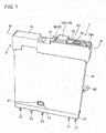
- an electromagnetic relay 1 includes a slide switch 2, a base plate 10, a coil block 20, a contact mechanism 30, and a case 40.
- the coil block 20, the contact mechanism 30, and the case 40 are mounted on the base plate 10.
- the slide switch 2 is mounted on the case 40.
- the coil block 20 and the contact mechanism 30 are housed in the case 40.
- the base plate 10 is formed into a rectangular shape as seen in plan view, and is made of an insulative resin.
- the base plate 10 includes an insulating wall 13 for dividing the base plate 10 into a first area 11 where the coil block 20 is mounted and a second area 12 where the contact mechanism 30 is mounted.
- the insulating wall 13 has case mounting projections 14 and 14 formed on both side surfaces thereof ( Figs. 6 and 7 illustrate only one of the case mounting projections 14 and 14).
- the insulating wall 13 also has card mounting holes 18 and 18 formed above the case mounting projections 14 and 14. The card mounting holes 18 and 18 serve to mount a card 50 to be described later.
- the base plate 10 has terminal holes 15a and 15a formed in a bottom surface of the first area 11.
- the terminal holes 15a and 15a serve to receive a pair of coil terminals 21 and 21 of the coil block 20.
- the base plate 10 also has terminal holes 17a, 17b, and 17c, and insulators 16 and 16 formed in and on a bottom surface of the second area 12.
- the terminal holes 17a, 17b, and 17c serve to receive a first fixed contact terminal 32, a movable contact terminal 31, and a second fixed contact terminal 33 (each of which will be described later) of the contact mechanism 30.
- the insulators 16 and 16 serve to fix the first fixed contact terminal 32 and the second fixed contact terminal 33 of the contact mechanism 30.
- the movable contact terminal 31 is located between the insulators 16 and 16.
- the coil block 20 includes the pair of coil terminals 21 and 21, a spool 22, a coil 23, an iron core 25, and a yoke 26.
- the spool 22 has a through hole 24 formed therein.
- the coil 23 is wound around the spool 22.
- the iron core 25 is inserted into the through hole 24.
- the yoke 26 is formed into a substantially "L" shape and is fixed by crimping to a lower end of the iron core 25.
- Each of the coil terminals 21 and 21 protrudes from the bottom surface of the base plate 10, and is fixed to a flange 22a formed on a lower end of the spool 22.
- the yoke 26 includes a horizontal part 26a and a vertical surface part 26b.
- the horizontal part 26a is fixed by crimping to the lower end of the iron core 25.
- the vertical surface part 26b extends upward along the coil 23.
- a hinge spring 27 is fixed by crimping to an upper end of a side surface of the vertical surface part 26b.
- the contact mechanism 30 includes a movable contact strip 31 a, a first fixed contact strip 32a, and a second fixed contact strip 33a.
- the movable contact strip 31 a is located between the first fixed contact strip 32a and the second fixed contact strip 33a.
- the movable contact strip 31 a has a movable contact 31 b formed on an upper end thereof, and the movable contact terminal 31 formed on a lower end thereof and bent in a crank shape.
- the movable contact 31 b is integrated with the movable contact strip 31 a such that the movable contact strip 31 a is located at a center of the movable contact strip 31 a.
- the first fixed contact strip 32a has a normally-opened first fixed contact 32b fixed by crimping to an upper end thereof, and the first fixed contact terminal 32 formed on a lower end thereof.
- the second fixed contact strip 33a is formed of a plate having an opening 33c formed therein.
- the second fixed contact strip 33a has a normally-closed second fixed contact 33b fixed by crimping to an upper end thereof, and the second fixed contact terminal 33 formed on a lower end thereof and bent in a crank shape.
- the movable contact terminal 31, the first fixed contact terminal 32, and the second fixed contact terminal 33 protrude from the bottom surface of the base plate 10.
- the card 50 and a movable steel piece 60 are disposed between the coil block 20 and the contact mechanism 30.
- the card 50 includes a card main body 51, and a pushing protrusion 52 formed at a center of one surface of the card main body 51. A distal end of the pushing protrusion 52 passes through the opening 33c in the second fixed contact strip 33a.
- the card 50 also includes a press receiver 53 formed on the other surface of the card main body 51, that is, an opposite surface to the surface where the pushing protrusion 52 is formed. The press receiver 53 serves to join the card 50 and the movable steel piece 60 together.
- the card main body 51 has a pair of elastic pieces 54 and 54 formed on one end thereof with a predetermined clearance created between the elastic pieces 54 and 54.
- the elastic pieces 54 and 54 have columnar card mounting projections 55 and 55 formed on side surfaces thereof at free end sides.
- the card mounting projections 55 and 55 are fitted into the card mounting holes 18 and 18 of the base plate 10, so that the card 50 is mounted on the base plate 10 in a turnable manner.
- the movable steel piece 60 is formed into a substantially "L" shape, and includes a press receiving part 61 and a joint arm part 62.
- the press receiving part 61 is pressed by an elastic test button 90 of the slide switch 2, and the joint arm part 62 is narrower in width than the press receiving part 61.
- the movable steel piece 60 is disposed to be rotatable about the upper end of the vertical surface part 26b of the yoke 26.
- the movable steel piece 60 is also disposed such that the joint arm part 62 comes into contact with the press receiver 53 of the card 50.
- the movable steel piece 60 is supported by the hinge spring 27, which is attached to the vertical surface part 26b of the yoke 26, such that a center of rotation thereof is not displaced.
- the case 40 is formed into a box shape, has an opening formed in one surface thereof, and is made of a translucent resin.
- the case 40 has case mounting holes 41 and 41 formed at centers of two edges of the opening.
- the case mounting projections 14 and 14 of the base plate 10 are fitted into the case mounting holes 41 and 41, so that the case 40 is mounted on the base plate 10.
- the case 40 also has a claw 42 formed on a side end surface thereof facing the coil block 20. In a state in which the electromagnetic relay 1 is mounted on a panel (not illustrated), a user hitches his/her finger on the claw 42, thereby removing the electromagnetic relay 1 from the panel.
- the case 40 also has mounting grooves 43 and 43 formed on side end surfaces of an upper end thereof.
- the mounting grooves 43 and 43 serve to mount the slide switch 2.
- the case 40 also has a hollow bump 44 and an actuation hole 45 each formed on a top surface thereof.
- the elastic test button 90 is disposed in the actuation hole 45.
- the hollow bump 44 receives an upper end of the card 50.
- the actuation hole 45 is located on the press receiving part 61 of the movable steel piece 60.
- the case 40 also has a supporting wall 46 formed on one of outer edges of the actuation hole 45. The supporting wall 46 serves to support the elastic test button 90.
- the slide switch 2 includes a cover 70, a slide lever 80, the elastic test button 90, and a stopper 100.
- the cover 70 is mounted on the top surface of the case 40.
- the slide lever 80 and the elastic test button 90 are housed in the cover 70.
- the stopper 100 is mounted on a top surface of the cover 70 so as to be turnable by 180°.
- the elastic test button 90 is inserted into the actuation hole 45 in the case 40.
- the slide lever 80 is disposed on the elastic test button 90 in a slidable manner.
- the cover 70 has an operation hole 71 formed in the top surface thereof.
- the operation hole 71 allows the sliding operation of the slide lever 80.
- the cover 70 also has a set of erroneous operation preventing walls 72 and 72 formed on edges of the operation hole 71.
- the erroneous operation preventing walls 72 and 72 extend along a sliding direction D of the slide lever 80 to prevent erroneous operation of the slide lever 80.
- the cover 70 also has bearings 77 and 77, positioning holes 79a and 79a, and positioning holes 79b and 79b formed on and in inner side surfaces of the erroneous operation preventing walls 72 and 72.
- the bearings 77 and 77 serve to support the stopper 100 in a turnable manner.
- the positioning holes 79a and 79a and the positioning holes 79b and 79b serve to set the position of the stopper 100.
- the cover 70 also has a supporting bump 76 formed on an end thereof so as to protrude from the top surface thereof.
- the supporting bump 76 serves to support the stopper 100.
- the supporting bump 76 has a recess 78 formed in one side surface thereof.
- the recess 78 serves to support, together with the bearings 77 and 77, the stopper 100 in a turnable manner.
- the recess 78 is formed to face one of the bearings 77 and 77.
- the cover 70 also has mounting claws 73 and 73 formed on both end surfaces thereof in the longitudinal direction.
- the mounting claws 73 and 73 are fitted into the mounting grooves 43 and 43 of the case 40 such that the cover 70 is mounted on the case 40.
- the cover 70 also has a pair of grooves, that is, a first groove 74 and a second groove 75 formed in an inner surface, that is, an inner side surface 70a thereof.
- the first groove 74 serves to maintain the slide lever 80 at a return position
- the second groove 75 serves to maintain the slide lever 80 at an actuation position.
- the first groove 74, the second groove 75, and an elastic locking claw 82 (which will be described later) of the slide lever 80 constitute a locking mechanism.
- the slide lever 80 includes a main body 81, the elastic locking claw 82, a slide support 84, and a pressing projection 85 which are integrally formed.
- the main body 81 is formed into a plate shape, and is larger than the operation hole 71 of the cover 70.
- the main body 81 has a planar shape to block the operation hole 71 irrespective of the position of the slide lever 80.
- the elastic locking claw 82 is formed into an "R" shape as seen in plan view (see Figs. 6 and 7 ), and extends from the main body 81 along the sliding direction D of the slide lever 80.
- the "R"-shaped elastic locking claw 82 can secure elastic force and prolong the lifetime of the slide lever 80 by spreading force to be applied to a joint portion between the main body 81 and the elastic locking claw 82.
- the slide lever 80 has an operating projection 83 formed on a top surface of the main body 81.
- the operating projection 83 has a groove formed at a center thereof, and is formed into a substantially cubic shape.
- the operating projection 83 facilitates the sliding operation of the slide lever 80.
- the center groove allows the user to handle the electromagnetic relay 1 with a screwdriver or the like.
- the slide lever 80 does not necessarily have such a groove.
- the slide support 84 is formed into a substantially rectangular column shape, and protrudes from a substantially center of a bottom surface of the main body 81.
- the slide support 84 has a length substantially equal to a distance from the bottom surface of the main body 81 to the top surface of the case 40 in the state in which the slide lever 80 is in press contact with a ceiling surface 70b of the cover 70.
- the pressing projection 85 is formed into a trapezoid shape as seen in side view, and protrudes from the bottom surface of the main body 81 at an end where the elastic locking claw 82 is formed.
- the pressing projection 85 has an inclined side surface which faces the elastic locking claw 82.
- the return position of the slide lever 80 corresponds to the position of the slide lever 80 in the state in which the movable contact 31 b and the normally-closed second fixed contact 33b are in contact with each other in the contact mechanism 30 (i.e., the contact mechanism 30 is in the return state).
- the actuation position of the slide lever 80 corresponds to the position of the slide lever 80 in the state in which the movable contact 31 b and the normally-opened first fixed contact 32b are in contact with each other in the contact mechanism 30 (i.e., the contact mechanism 30 is in the actuation state).
- the elastic test button 90 is formed into a substantially " ⁇ " shape as seen in sectional view, and includes a flat plate part 91, elastic arm parts 92 and 92, and a protruding part 93 which are formed by integral molding.
- the flat plate part 91 is formed into a square shape as seen in plan view.
- the elastic arm parts 92 and 92 are formed on opposite corners of the flat plate part 91.
- the protruding part 93 protrudes from the flat plate part 91 at a position between the elastic arm parts 92 and 92.
- the elastic arm parts 92 and 92 linearly extend from two corners on one side of the flat plate part 91 along an orthogonal side to the side so as to be angled with respect to the flat plate part 91.
- the protruding part 93 has two elastic pieces 93a and 93a with a clearance created between the elastic pieces 93a and 93a.
- the protruding part 93 also has claws 93b and 93b formed on distal ends of outward surfaces of the elastic pieces 93a and 93a. The claws 93b and 93b are caught on an inner edge of the actuation hole 45 in the case 40 to prevent disconnection of the elastic test button 90.
- the protruding part 93 also has extruding protuberances 93c and 93c formed on inward surfaces of the elastic pieces 93a and 93a at positions where the protuberances 93c and 93c do not face each other.
- the extruding protuberances 93c and 93c are used for extruding the elastic test button 90 from a molding die.
- the stopper 100 includes a stopper main body 101 and an operating flat plate 102 formed on the stopper main body 101.
- the stopper main body 101 has a pair of arms 103 and 104 formed to protrude from one end thereof so as to face each other.
- the arms 103 and 104 have column-shaped first and second shafts 105 and 106 formed on distal ends thereof, respectively.
- the first and second shafts 105 and 106 extend in a widthwise direction W of the stopper main body 101, and have shaft projections 105a and 106a formed on outward ends thereof, respectively.
- the first shaft 105 has both ends protruding from the arm 103.
- the outward end can be attached to the bearing 77 of the erroneous operation preventing wall 72, and the inward end can be fitted into the recess 78 of the supporting bump 76.
- the second shaft 106 has an outward end protruding from the arm 104, and this outward end can be attached to the bearing 77 of the erroneous operation preventing wall 72.
- the first shaft 105 and the second shaft 106 each serve as an axis of turn of the stopper 100, and are arranged coaxially.
- the stopper main body 101 also has positioning projections 107 and 107 formed on both side surfaces thereof, respectively.
- the positioning projections 107 and 107 can be fitted into the positioning holes 79a and 79b in the erroneous operation preventing wall 72 of the cover 70.
- the operating flat plate 102 is formed into a rectangular shape as seen in plan view, and is integrally formed on the stopper main body 101.
- the size of the operating flat plate 102 in the widthwise direction W is substantially equal to the width of the cover 70.
- the operating flat plate 102 facilitates the operation of the stopper 100.
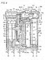
- the electromagnetic relay 1 is assembled in the return state illustrated in Fig. 4 (the state in which the slide lever 80 is located at the return position and the contact mechanism 30 is in the return state).
- the coil block 20 is assembled in advance.
- the coil terminals 21 and 21 are press fitted into the flange 22a of the spool 22. Both the ends of the coil 23 are wound around the coil terminals 21 and 21, respectively.
- the movable contact terminal 31 of the movable contact strip 31 a, the first fixed contact terminal 32 of the first fixed contact strip 32a, and the second fixed contact terminal 33 of the second fixed contact strip 33a are press fitted into the base plate 10 so as to protrude from the bottom surface of the base plate 10, respectively.
- the movable contact 31 b and the normally-closed second fixed contact 33b are in contact with each other.
- the movable contact 31 b and the normally-opened first fixed contact 32b face each other in a contactable and separatable manner.
- the card 50 is mounted on the base plate 10 such that the distal end of the pushing protrusion 52 of the card 50 passes through the opening 33c of the second fixed contact strip 33a.
- the coil block 20 is mounted on the base plate 10 such that the coil terminals 21 and 21 protrude from the bottom surface of the base plate 10.
- the movable steel piece 60 is disposed to be rotatable about the upper end of the vertical surface part 26b of the yoke 26.
- the movable steel piece 60 is disposed such that the joint arm part 62 comes into contact with the press receiver 53 of the card 50.
- the movable steel piece 60 is in contact with the press receiver 53 of the card 50, but does not press the card 50 toward the contact mechanism 30.
- the case 40 is mounted on the base plate 10. Subsequently, the elastic test button 90 is inserted into the actuation hole 45 in the case 40. Moreover, the slide lever 80 is disposed on the case 40. Further, the cover 70 is mounted on the case 40 such that the elastic locking claw 82 of the slide lever 80 is located at the first groove 74 of the cover 70.
- the elastic test button 90 presses the slide lever 80 so as to bring the elastic locking claw 82 into press contact with the ceiling surface 70b of the cover 70 with the elastic force of the elastic arm part 92.
- the slide support 84 and the elastic test button 90 support the slide lever 80 such that the slide lever 80 can be always maintained at a state substantially parallel with the ceiling surface 70b of the cover 70. Therefore, the clearance between the slide lever 80 and the operation hole 71 in the cover 70 can be securely blocked in the state in which the slide lever 80 is located at the return position.
- the stopper 100 is mounted on the cover 70.
- the stopper 100 is mounted so as to be turnable about the first and second shafts 105 and 106 in the sliding direction of the slide lever 80.
- the operating direction of the slide lever 80 and the operating direction of the stopper 100 can be synchronized with each other, so that the user can easily determine whether or not the slide lever 80 is restricted to the return position.
- the top surface and bottom surface of the stopper 100 are colored with different colors, respectively, the user can more easily determine whether or not the slide lever 80 is restricted to the return position.
- the stopper 100 may be mounted on the cover 70 in advance.
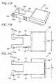
- the stopper 100 In the state in which the slide lever 80 is located at the return position, the stopper 100 is disposed at the position illustrated in Fig. 1 (the restriction position). As illustrated in Fig. 4 , the stopper main body 101 blocks the operation hole 71 except a portion where the operating projection 83 protrudes, to thereby securely restrict the slide lever 80 to the return position. Moreover, the positioning projection 107 of the stopper main body 101 is fitted into the positioning hole 79a in the erroneous operation preventing wall 72. Thus, the stopper 100 is set at the restriction position.
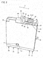
- the stopper 100 In order to move the slide lever 80 to the actuation position, the stopper 100 is turned to the position illustrated in Fig. 2 (release position) to open the operation hole 71. Thus, the stopper 100 releases the restriction to the sliding operation of the slide lever 80.
- the positioning projection 107 of the stopper main body 101 is fitted into the positioning hole 79b in the erroneous operation preventing wall 72. Thus, the stopper 100 is set at the release position. The stopper 100 does not disturb the sliding operation of the slide lever 80, and therefore can ensure the favorable sliding operation of the slide lever 80.
- the elastic arm parts 92 and 92 of the elastic test button 90 press the slide lever 80 with the elastic force. Therefore, the slide lever 80 is in press contact with the ceiling surface 70b of the cover 70.
- the supporting wall 46 of the case 40 supports the force to be applied to the elastic test button 90 by the pressing projection 85 in the sliding direction D.
- the elastic test button 90 can be prevented from dropping out of the actuation hole 45 because of the sliding operation of the slide lever 80. Further, the elastic test button 90 can securely move in an orthogonal direction to the top surface of the case 40.
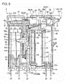
- the slide lever 80 moves to the actuation position to push the elastic test button 90 into the case 40, so that the elastic test button 90 presses the press receiving part 61 of the movable steel piece 60 against the coil block 20.
- the press receiving part 61 of the movable steel piece 60 comes into press contact with a magnetic plate 25a of the iron core 25.
- the joint arm part 62 pushes the card 50 toward the contact mechanism 30.
- the pushing protrusion 52 of the card 50 pushes the movable contact strip 31 a toward the first fixed contact strip 32a to elastically deform the movable contact strip 31a.
- the movable contact 31 b comes into contact with the normally-opened first fixed contact 32b.
- the actuation state illustrated in Fig. 5 is established.
- the locking mechanism constituted of the elastic locking claw 82 of the slide lever 80, the first groove 74, and the second groove 75 is capable of ensuring the pressing force applied to the slide lever 80 by the elastic test button 90, and is also capable of maintaining the slide lever 80 at the actuation position and the return position.
- the card 50 returns together with the movable contact 31 b to the return state with the elastic force of the movable contact strip 31 a.
- the electromagnetic relay 1 opens and closes the contact of the contact mechanism 30 in conjunction with the actuation of the elastic test button 90 according to the sliding operation of the slide lever 80.
- the electromagnetic relay 1 includes the stopper 100 capable of restricting the slide lever 80 to the return position for bringing the contact mechanism 30 into the return state.
- the stopper 100 can prevent erroneous operation of the slide lever 80, and also can prevent an unintentional change in open and close states of the movable contact 31 b.
- the stopper 100 can be set at the restriction position and the release position. Therefore, the user can clearly determine whether or not the slide lever 80 is located at the return position. Thus, the stopper 100 can prevent the user from erroneously operating the slide lever 80.
- the electromagnetic relay 1 may employ any other contact mechanisms in addition to the contact mechanism 30.
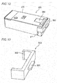
- the electromagnetic relay 1 is not limited to the configuration employing the slide switch 2, but may include a slide switch 202 illustrated in Fig. 12 .
- the slide switch 202 includes a cover 270, a slide lever 280, and a stopper 300.
- the slide lever 280 is disposed to be slidable via an operation hole formed in one of longitudinal ends of the cover 270.
- the stopper 300 is formed into a substantially lateral "U" shape, and includes a holding part 301 and fitting projections 302 and 302.
- the slide lever can be restricted to an arbitrary position in such a manner that the shapes of the slide lever and stopper are changed in accordance with the design and the like of the slide switch.
- the cover 70 has the set of erroneous operation preventing walls 72 and 72 protruding from the two edges of the operation hole 71 along the sliding direction D of the slide lever 80; however, the disclosure is not limited thereto.
- the erroneous operation preventing wall 72 may be formed on at least one of the two edges of the operation hole 71.
- the return position of the slide lever 80 corresponds to position of the slide lever 80 in the state in which the normally-closed second fixed contact 33b and the movable contact 31 b are in contact with each other in the contact mechanism 30; however, the disclosure is not limited thereto.
- the electromagnetic relay 1 does not necessarily include the second fixed contact (normally-closed fixed contact).
- the return position of the slide lever may be a position of the slide lever in a state in which the movable contact and the first fixed contact (normally-opened fixed contact) are not in contact with each other.
- the electromagnetic relay 1 including the slide switch 2 is not particularly limited to the foregoing embodiment of the disclosure so long as to have the following configuration. That is, the electromagnetic relay includes a slide lever which is slidable via an operation hole, and a stopper which is disposed to restrict the position of the slide lever.
Landscapes
- Physics & Mathematics (AREA)
- Electromagnetism (AREA)
- Switch Cases, Indication, And Locking (AREA)
- Push-Button Switches (AREA)
Applications Claiming Priority (1)
| Application Number | Priority Date | Filing Date | Title |
|---|---|---|---|
| JP2014047808A JP6287378B2 (ja) | 2014-03-11 | 2014-03-11 | 電磁継電器 |
Publications (2)
| Publication Number | Publication Date |
|---|---|
| EP2919253A1 true EP2919253A1 (de) | 2015-09-16 |
| EP2919253B1 EP2919253B1 (de) | 2017-08-02 |
Family
ID=52595066
Family Applications (1)
| Application Number | Title | Priority Date | Filing Date |
|---|---|---|---|
| EP15155194.2A Active EP2919253B1 (de) | 2014-03-11 | 2015-02-16 | Elektromagnetisches Relais |
Country Status (2)
| Country | Link |
|---|---|
| EP (1) | EP2919253B1 (de) |
| JP (1) | JP6287378B2 (de) |
Cited By (1)
| Publication number | Priority date | Publication date | Assignee | Title |
|---|---|---|---|---|
| CN107845542A (zh) * | 2017-11-23 | 2018-03-27 | 国网山东省电力公司烟台供电公司 | 一种便于拆装的继电器模组 |
Citations (8)
| Publication number | Priority date | Publication date | Assignee | Title |
|---|---|---|---|---|
| JPS5349682U (de) * | 1976-09-30 | 1978-04-26 | ||
| JPS5568222U (de) * | 1978-11-01 | 1980-05-10 | ||
| JPS638542U (de) * | 1986-07-01 | 1988-01-20 | ||
| GB2230384A (en) * | 1989-04-13 | 1990-10-17 | Telemecanique | Electromagnetic switch with lockable forced operation |
| JPH1196875A (ja) | 1997-07-01 | 1999-04-09 | Eh Schrack Components Ag | 手操作機構を備えた電磁リレー |
| EP1487001A1 (de) * | 2003-04-24 | 2004-12-15 | Omron Corporation | Elektromagnetisches Relais |
| US20060278504A1 (en) * | 2005-05-27 | 2006-12-14 | Michael Brojanac | Mountable lockout device |
| US20090218202A1 (en) * | 2008-02-28 | 2009-09-03 | Fujitsu Siemens Computers Gmbh | Housing with a sliding switch |
Family Cites Families (2)
| Publication number | Priority date | Publication date | Assignee | Title |
|---|---|---|---|---|
| JPS59103326U (ja) * | 1982-12-27 | 1984-07-11 | パイオニア株式会社 | スイツチ機構 |
| JP4168819B2 (ja) * | 2003-04-24 | 2008-10-22 | オムロン株式会社 | 電磁継電器 |
-
2014
- 2014-03-11 JP JP2014047808A patent/JP6287378B2/ja active Active
-
2015
- 2015-02-16 EP EP15155194.2A patent/EP2919253B1/de active Active
Patent Citations (8)
| Publication number | Priority date | Publication date | Assignee | Title |
|---|---|---|---|---|
| JPS5349682U (de) * | 1976-09-30 | 1978-04-26 | ||
| JPS5568222U (de) * | 1978-11-01 | 1980-05-10 | ||
| JPS638542U (de) * | 1986-07-01 | 1988-01-20 | ||
| GB2230384A (en) * | 1989-04-13 | 1990-10-17 | Telemecanique | Electromagnetic switch with lockable forced operation |
| JPH1196875A (ja) | 1997-07-01 | 1999-04-09 | Eh Schrack Components Ag | 手操作機構を備えた電磁リレー |
| EP1487001A1 (de) * | 2003-04-24 | 2004-12-15 | Omron Corporation | Elektromagnetisches Relais |
| US20060278504A1 (en) * | 2005-05-27 | 2006-12-14 | Michael Brojanac | Mountable lockout device |
| US20090218202A1 (en) * | 2008-02-28 | 2009-09-03 | Fujitsu Siemens Computers Gmbh | Housing with a sliding switch |
Cited By (1)
| Publication number | Priority date | Publication date | Assignee | Title |
|---|---|---|---|---|
| CN107845542A (zh) * | 2017-11-23 | 2018-03-27 | 国网山东省电力公司烟台供电公司 | 一种便于拆装的继电器模组 |
Also Published As
| Publication number | Publication date |
|---|---|
| EP2919253B1 (de) | 2017-08-02 |
| JP6287378B2 (ja) | 2018-03-07 |
| JP2015173020A (ja) | 2015-10-01 |
Similar Documents
| Publication | Publication Date | Title |
|---|---|---|
| EP2637184B1 (de) | Schalter | |
| EP2889886B1 (de) | Elektromagnetisches Relais | |
| JP2016115550A (ja) | 押しボタンスイッチ | |
| JPS6285402A (ja) | 引き金操作式携帯電気工具用スイツチ | |
| JPH05217464A (ja) | プッシュ機構付きスライドスイッチ | |
| KR101408132B1 (ko) | 콘센트 안전장치 | |
| EP2919253B1 (de) | Elektromagnetisches Relais | |
| US8664555B2 (en) | Trip button mechanism of external handle for circuit breaker | |
| WO2012090521A1 (ja) | スイッチ | |
| EP2413339B1 (de) | Schalter und elektronische Vorrichtung | |
| US7922505B2 (en) | Card connector | |
| JP6535599B2 (ja) | 端子装置 | |
| EP2757567B1 (de) | Schalter mit Druckknopf | |
| JP4256708B2 (ja) | スイッチ装置 | |
| JPS6336921Y2 (de) | ||
| TW420812B (en) | Pushbutton switch | |
| JP2858871B2 (ja) | ピアノハンドル式スイッチ | |
| JP2007317515A (ja) | 接続器具 | |
| JPH0637547Y2 (ja) | スイツチ操作装置 | |
| KR200205038Y1 (ko) | 푸쉬버튼 스위치의 작동캠 장치 | |
| JPH0228571Y2 (de) | ||
| JPH0741065Y2 (ja) | 自動復帰型スライドスイッチ | |
| JP3878392B2 (ja) | スイッチ装置 | |
| JPH0143786Y2 (de) | ||
| JP2513245B2 (ja) | 小型スイッチ |
Legal Events
| Date | Code | Title | Description |
|---|---|---|---|
| PUAI | Public reference made under article 153(3) epc to a published international application that has entered the european phase |
Free format text: ORIGINAL CODE: 0009012 |
|
| AK | Designated contracting states |
Kind code of ref document: A1 Designated state(s): AL AT BE BG CH CY CZ DE DK EE ES FI FR GB GR HR HU IE IS IT LI LT LU LV MC MK MT NL NO PL PT RO RS SE SI SK SM TR |
|
| AX | Request for extension of the european patent |
Extension state: BA ME |
|
| 17P | Request for examination filed |
Effective date: 20160315 |
|
| RBV | Designated contracting states (corrected) |
Designated state(s): AL AT BE BG CH CY CZ DE DK EE ES FI FR GB GR HR HU IE IS IT LI LT LU LV MC MK MT NL NO PL PT RO RS SE SI SK SM TR |
|
| GRAP | Despatch of communication of intention to grant a patent |
Free format text: ORIGINAL CODE: EPIDOSNIGR1 |
|
| STAA | Information on the status of an ep patent application or granted ep patent |
Free format text: STATUS: GRANT OF PATENT IS INTENDED |
|
| RIC1 | Information provided on ipc code assigned before grant |
Ipc: H01H 15/10 20060101ALN20170127BHEP Ipc: H01H 50/32 20060101AFI20170127BHEP Ipc: H01H 9/28 20060101ALN20170127BHEP |
|
| INTG | Intention to grant announced |
Effective date: 20170217 |
|
| GRAS | Grant fee paid |
Free format text: ORIGINAL CODE: EPIDOSNIGR3 |
|
| GRAA | (expected) grant |
Free format text: ORIGINAL CODE: 0009210 |
|
| STAA | Information on the status of an ep patent application or granted ep patent |
Free format text: STATUS: THE PATENT HAS BEEN GRANTED |
|
| AK | Designated contracting states |
Kind code of ref document: B1 Designated state(s): AL AT BE BG CH CY CZ DE DK EE ES FI FR GB GR HR HU IE IS IT LI LT LU LV MC MK MT NL NO PL PT RO RS SE SI SK SM TR |
|
| REG | Reference to a national code |
Ref country code: CH Ref legal event code: EP Ref country code: AT Ref legal event code: REF Ref document number: 915317 Country of ref document: AT Kind code of ref document: T Effective date: 20170815 |
|
| REG | Reference to a national code |
Ref country code: IE Ref legal event code: FG4D |
|
| REG | Reference to a national code |
Ref country code: DE Ref legal event code: R096 Ref document number: 602015003798 Country of ref document: DE |
|
| REG | Reference to a national code |
Ref country code: NL Ref legal event code: MP Effective date: 20170802 |
|
| REG | Reference to a national code |
Ref country code: AT Ref legal event code: MK05 Ref document number: 915317 Country of ref document: AT Kind code of ref document: T Effective date: 20170802 |
|
| REG | Reference to a national code |
Ref country code: LT Ref legal event code: MG4D |
|
| PG25 | Lapsed in a contracting state [announced via postgrant information from national office to epo] |
Ref country code: NO Free format text: LAPSE BECAUSE OF FAILURE TO SUBMIT A TRANSLATION OF THE DESCRIPTION OR TO PAY THE FEE WITHIN THE PRESCRIBED TIME-LIMIT Effective date: 20171102 Ref country code: NL Free format text: LAPSE BECAUSE OF FAILURE TO SUBMIT A TRANSLATION OF THE DESCRIPTION OR TO PAY THE FEE WITHIN THE PRESCRIBED TIME-LIMIT Effective date: 20170802 Ref country code: SE Free format text: LAPSE BECAUSE OF FAILURE TO SUBMIT A TRANSLATION OF THE DESCRIPTION OR TO PAY THE FEE WITHIN THE PRESCRIBED TIME-LIMIT Effective date: 20170802 Ref country code: AT Free format text: LAPSE BECAUSE OF FAILURE TO SUBMIT A TRANSLATION OF THE DESCRIPTION OR TO PAY THE FEE WITHIN THE PRESCRIBED TIME-LIMIT Effective date: 20170802 Ref country code: LT Free format text: LAPSE BECAUSE OF FAILURE TO SUBMIT A TRANSLATION OF THE DESCRIPTION OR TO PAY THE FEE WITHIN THE PRESCRIBED TIME-LIMIT Effective date: 20170802 Ref country code: HR Free format text: LAPSE BECAUSE OF FAILURE TO SUBMIT A TRANSLATION OF THE DESCRIPTION OR TO PAY THE FEE WITHIN THE PRESCRIBED TIME-LIMIT Effective date: 20170802 Ref country code: FI Free format text: LAPSE BECAUSE OF FAILURE TO SUBMIT A TRANSLATION OF THE DESCRIPTION OR TO PAY THE FEE WITHIN THE PRESCRIBED TIME-LIMIT Effective date: 20170802 |
|
| PG25 | Lapsed in a contracting state [announced via postgrant information from national office to epo] |
Ref country code: RS Free format text: LAPSE BECAUSE OF FAILURE TO SUBMIT A TRANSLATION OF THE DESCRIPTION OR TO PAY THE FEE WITHIN THE PRESCRIBED TIME-LIMIT Effective date: 20170802 Ref country code: ES Free format text: LAPSE BECAUSE OF FAILURE TO SUBMIT A TRANSLATION OF THE DESCRIPTION OR TO PAY THE FEE WITHIN THE PRESCRIBED TIME-LIMIT Effective date: 20170802 Ref country code: LV Free format text: LAPSE BECAUSE OF FAILURE TO SUBMIT A TRANSLATION OF THE DESCRIPTION OR TO PAY THE FEE WITHIN THE PRESCRIBED TIME-LIMIT Effective date: 20170802 Ref country code: IS Free format text: LAPSE BECAUSE OF FAILURE TO SUBMIT A TRANSLATION OF THE DESCRIPTION OR TO PAY THE FEE WITHIN THE PRESCRIBED TIME-LIMIT Effective date: 20171202 Ref country code: BG Free format text: LAPSE BECAUSE OF FAILURE TO SUBMIT A TRANSLATION OF THE DESCRIPTION OR TO PAY THE FEE WITHIN THE PRESCRIBED TIME-LIMIT Effective date: 20171102 Ref country code: PL Free format text: LAPSE BECAUSE OF FAILURE TO SUBMIT A TRANSLATION OF THE DESCRIPTION OR TO PAY THE FEE WITHIN THE PRESCRIBED TIME-LIMIT Effective date: 20170802 Ref country code: GR Free format text: LAPSE BECAUSE OF FAILURE TO SUBMIT A TRANSLATION OF THE DESCRIPTION OR TO PAY THE FEE WITHIN THE PRESCRIBED TIME-LIMIT Effective date: 20171103 |
|
| PG25 | Lapsed in a contracting state [announced via postgrant information from national office to epo] |
Ref country code: CZ Free format text: LAPSE BECAUSE OF FAILURE TO SUBMIT A TRANSLATION OF THE DESCRIPTION OR TO PAY THE FEE WITHIN THE PRESCRIBED TIME-LIMIT Effective date: 20170802 Ref country code: DK Free format text: LAPSE BECAUSE OF FAILURE TO SUBMIT A TRANSLATION OF THE DESCRIPTION OR TO PAY THE FEE WITHIN THE PRESCRIBED TIME-LIMIT Effective date: 20170802 Ref country code: RO Free format text: LAPSE BECAUSE OF FAILURE TO SUBMIT A TRANSLATION OF THE DESCRIPTION OR TO PAY THE FEE WITHIN THE PRESCRIBED TIME-LIMIT Effective date: 20170802 |
|
| REG | Reference to a national code |
Ref country code: DE Ref legal event code: R097 Ref document number: 602015003798 Country of ref document: DE |
|
| PG25 | Lapsed in a contracting state [announced via postgrant information from national office to epo] |
Ref country code: SM Free format text: LAPSE BECAUSE OF FAILURE TO SUBMIT A TRANSLATION OF THE DESCRIPTION OR TO PAY THE FEE WITHIN THE PRESCRIBED TIME-LIMIT Effective date: 20170802 Ref country code: SK Free format text: LAPSE BECAUSE OF FAILURE TO SUBMIT A TRANSLATION OF THE DESCRIPTION OR TO PAY THE FEE WITHIN THE PRESCRIBED TIME-LIMIT Effective date: 20170802 Ref country code: IT Free format text: LAPSE BECAUSE OF FAILURE TO SUBMIT A TRANSLATION OF THE DESCRIPTION OR TO PAY THE FEE WITHIN THE PRESCRIBED TIME-LIMIT Effective date: 20170802 Ref country code: EE Free format text: LAPSE BECAUSE OF FAILURE TO SUBMIT A TRANSLATION OF THE DESCRIPTION OR TO PAY THE FEE WITHIN THE PRESCRIBED TIME-LIMIT Effective date: 20170802 |
|
| PLBE | No opposition filed within time limit |
Free format text: ORIGINAL CODE: 0009261 |
|
| STAA | Information on the status of an ep patent application or granted ep patent |
Free format text: STATUS: NO OPPOSITION FILED WITHIN TIME LIMIT |
|
| 26N | No opposition filed |
Effective date: 20180503 |
|
| PG25 | Lapsed in a contracting state [announced via postgrant information from national office to epo] |
Ref country code: SI Free format text: LAPSE BECAUSE OF FAILURE TO SUBMIT A TRANSLATION OF THE DESCRIPTION OR TO PAY THE FEE WITHIN THE PRESCRIBED TIME-LIMIT Effective date: 20170802 |
|
| REG | Reference to a national code |
Ref country code: CH Ref legal event code: PL |
|
| PG25 | Lapsed in a contracting state [announced via postgrant information from national office to epo] |
Ref country code: MC Free format text: LAPSE BECAUSE OF FAILURE TO SUBMIT A TRANSLATION OF THE DESCRIPTION OR TO PAY THE FEE WITHIN THE PRESCRIBED TIME-LIMIT Effective date: 20170802 |
|
| REG | Reference to a national code |
Ref country code: IE Ref legal event code: MM4A |
|
| REG | Reference to a national code |
Ref country code: BE Ref legal event code: MM Effective date: 20180228 |
|
| PG25 | Lapsed in a contracting state [announced via postgrant information from national office to epo] |
Ref country code: CH Free format text: LAPSE BECAUSE OF NON-PAYMENT OF DUE FEES Effective date: 20180228 Ref country code: LU Free format text: LAPSE BECAUSE OF NON-PAYMENT OF DUE FEES Effective date: 20180216 Ref country code: LI Free format text: LAPSE BECAUSE OF NON-PAYMENT OF DUE FEES Effective date: 20180228 |
|
| REG | Reference to a national code |
Ref country code: FR Ref legal event code: ST Effective date: 20181031 |
|
| PG25 | Lapsed in a contracting state [announced via postgrant information from national office to epo] |
Ref country code: IE Free format text: LAPSE BECAUSE OF NON-PAYMENT OF DUE FEES Effective date: 20180216 |
|
| PG25 | Lapsed in a contracting state [announced via postgrant information from national office to epo] |
Ref country code: BE Free format text: LAPSE BECAUSE OF NON-PAYMENT OF DUE FEES Effective date: 20180228 Ref country code: FR Free format text: LAPSE BECAUSE OF NON-PAYMENT OF DUE FEES Effective date: 20180228 |
|
| GBPC | Gb: european patent ceased through non-payment of renewal fee |
Effective date: 20190216 |
|
| PG25 | Lapsed in a contracting state [announced via postgrant information from national office to epo] |
Ref country code: MT Free format text: LAPSE BECAUSE OF NON-PAYMENT OF DUE FEES Effective date: 20180216 Ref country code: GB Free format text: LAPSE BECAUSE OF NON-PAYMENT OF DUE FEES Effective date: 20190216 |
|
| PG25 | Lapsed in a contracting state [announced via postgrant information from national office to epo] |
Ref country code: TR Free format text: LAPSE BECAUSE OF FAILURE TO SUBMIT A TRANSLATION OF THE DESCRIPTION OR TO PAY THE FEE WITHIN THE PRESCRIBED TIME-LIMIT Effective date: 20170802 |
|
| PG25 | Lapsed in a contracting state [announced via postgrant information from national office to epo] |
Ref country code: PT Free format text: LAPSE BECAUSE OF FAILURE TO SUBMIT A TRANSLATION OF THE DESCRIPTION OR TO PAY THE FEE WITHIN THE PRESCRIBED TIME-LIMIT Effective date: 20170802 |
|
| PG25 | Lapsed in a contracting state [announced via postgrant information from national office to epo] |
Ref country code: MK Free format text: LAPSE BECAUSE OF NON-PAYMENT OF DUE FEES Effective date: 20170802 Ref country code: CY Free format text: LAPSE BECAUSE OF FAILURE TO SUBMIT A TRANSLATION OF THE DESCRIPTION OR TO PAY THE FEE WITHIN THE PRESCRIBED TIME-LIMIT Effective date: 20170802 Ref country code: HU Free format text: LAPSE BECAUSE OF FAILURE TO SUBMIT A TRANSLATION OF THE DESCRIPTION OR TO PAY THE FEE WITHIN THE PRESCRIBED TIME-LIMIT; INVALID AB INITIO Effective date: 20150216 |
|
| PG25 | Lapsed in a contracting state [announced via postgrant information from national office to epo] |
Ref country code: AL Free format text: LAPSE BECAUSE OF FAILURE TO SUBMIT A TRANSLATION OF THE DESCRIPTION OR TO PAY THE FEE WITHIN THE PRESCRIBED TIME-LIMIT Effective date: 20170802 |
|
| PGFP | Annual fee paid to national office [announced via postgrant information from national office to epo] |
Ref country code: DE Payment date: 20240216 Year of fee payment: 10 |