EP2916733B1 - Längenmessgerät - Google Patents
Längenmessgerät Download PDFInfo
- Publication number
- EP2916733B1 EP2916733B1 EP13750048.4A EP13750048A EP2916733B1 EP 2916733 B1 EP2916733 B1 EP 2916733B1 EP 13750048 A EP13750048 A EP 13750048A EP 2916733 B1 EP2916733 B1 EP 2916733B1
- Authority
- EP
- European Patent Office
- Prior art keywords
- hollow profile
- length
- measuring device
- acoustic resonator
- inner slide
- Prior art date
- Legal status (The legal status is an assumption and is not a legal conclusion. Google has not performed a legal analysis and makes no representation as to the accuracy of the status listed.)
- Active
Links
Images
Classifications
-
- A—HUMAN NECESSITIES
- A61—MEDICAL OR VETERINARY SCIENCE; HYGIENE
- A61B—DIAGNOSIS; SURGERY; IDENTIFICATION
- A61B5/00—Measuring for diagnostic purposes; Identification of persons
- A61B5/103—Measuring devices for testing the shape, pattern, colour, size or movement of the body or parts thereof, for diagnostic purposes
- A61B5/107—Measuring physical dimensions, e.g. size of the entire body or parts thereof
- A61B5/1072—Measuring physical dimensions, e.g. size of the entire body or parts thereof measuring distances on the body, e.g. measuring length, height or thickness
-
- A—HUMAN NECESSITIES
- A61—MEDICAL OR VETERINARY SCIENCE; HYGIENE
- A61B—DIAGNOSIS; SURGERY; IDENTIFICATION
- A61B5/00—Measuring for diagnostic purposes; Identification of persons
- A61B5/72—Signal processing specially adapted for physiological signals or for diagnostic purposes
- A61B5/7235—Details of waveform analysis
- A61B5/7253—Details of waveform analysis characterised by using transforms
- A61B5/7257—Details of waveform analysis characterised by using transforms using Fourier transforms
-
- G—PHYSICS
- G01—MEASURING; TESTING
- G01B—MEASURING LENGTH, THICKNESS OR SIMILAR LINEAR DIMENSIONS; MEASURING ANGLES; MEASURING AREAS; MEASURING IRREGULARITIES OF SURFACES OR CONTOURS
- G01B17/00—Measuring arrangements characterised by the use of infrasonic, sonic or ultrasonic vibrations
-
- G—PHYSICS
- G01—MEASURING; TESTING
- G01B—MEASURING LENGTH, THICKNESS OR SIMILAR LINEAR DIMENSIONS; MEASURING ANGLES; MEASURING AREAS; MEASURING IRREGULARITIES OF SURFACES OR CONTOURS
- G01B5/00—Measuring arrangements characterised by the use of mechanical techniques
- G01B5/02—Measuring arrangements characterised by the use of mechanical techniques for measuring length, width or thickness
- G01B5/06—Measuring arrangements characterised by the use of mechanical techniques for measuring length, width or thickness for measuring thickness
- G01B5/061—Measuring arrangements characterised by the use of mechanical techniques for measuring length, width or thickness for measuring thickness height gauges
-
- A—HUMAN NECESSITIES
- A61—MEDICAL OR VETERINARY SCIENCE; HYGIENE
- A61B—DIAGNOSIS; SURGERY; IDENTIFICATION
- A61B2560/00—Constructional details of operational features of apparatus; Accessories for medical measuring apparatus
- A61B2560/02—Operational features
- A61B2560/0223—Operational features of calibration, e.g. protocols for calibrating sensors
-
- A—HUMAN NECESSITIES
- A61—MEDICAL OR VETERINARY SCIENCE; HYGIENE
- A61B—DIAGNOSIS; SURGERY; IDENTIFICATION
- A61B2562/00—Details of sensors; Constructional details of sensor housings or probes; Accessories for sensors
- A61B2562/02—Details of sensors specially adapted for in-vivo measurements
- A61B2562/0204—Acoustic sensors
Definitions
- the present invention relates to a length measuring device with a caliper, a linear guide in the form of a hollow profile on which the caliper is mounted on the outside displaceable in order to bring him into contact with an object to be measured with respect to its length, an internal slider inside the hollow profile is slidably mounted, a magnet assembly, the caliper and inner slide magnetically coupled, so that the inner slide follows each movement of the caliper along the hollow profile, a measuring device for measuring the position of the inner slider along the hollow profile and visible in the outer space of the hollow profile Display of the determined by the measuring device length in accordance with the measured position of the inner slider.
- the hollow profile is provided at least one end with an end wall. Further, the inner slider substantially covers the cross section of the hollow profile, so that a closed cavity is formed in the interior of the hollow profile between the end wall and the inner slider, which can serve as an acoustic resonator.
- the invention is particularly directed to length measuring devices for measuring the height of persons.
- Such length measuring devices are also referred to as Stadiometer.
- a typical such length measuring device has a measuring rod, which is designed as a vertical linear guide for a caliper (head slider).
- the dipstick is vertically aligned and mounted on a wall or attached to a platform.
- To measure the height of the person steps in front of the dipstick after which the head slider is pushed down on the dipstick until it comes in contact with the head of the person to be measured.
- a measuring scale with scale graduation lines is provided on the dipstick.
- a reading unit is present in the caliper, which registers the graduation graduation marks when the caliper is moved on the dipstick and thus detects the incremental change in the position of the caliper.
- the scale graduation lines may also encode the absolute height of a graduation scale, so that the height of the head slider is determined by the reading unit can be determined, which is then displayed on a gauge on the calliper.
- Another type of body length meter includes an elbow held by a person measuring the body length.
- One leg of the elbow is held in contact with the head of the person to be measured.
- a second leg is perpendicular from, wherein the elbow is held so that the second leg is directed vertically to the ground.
- a distance measuring device is provided with an ultrasonic transducer, which runs back from the running time of a transmitted ultrasonic signal, which is reflected at the bottom and the ultrasonic transducer, the height of the resting on the head of the person to be measured first leg above the ground and thus the body size determines and displays.
- a disadvantage of this type of length measuring device is that measurement inaccuracies can occur because the person conducting the measurement does not keep the angle piece exactly aligned so that the second leg is directed exactly vertically on the ground. Furthermore, it is disadvantageous that changing environmental conditions (for example dust or other impurities in the air) or objects lying on the floor can falsify the measurement.
- Another type of length measuring device has a platform on which the person to be measured occurs, and a horizontal support suspended vertically above the persons to be measured.
- a distance measuring device based on ultrasonic wave time is attached, which is directed to the head of standing on the platform to be measured person.
- the person to be measured wears a cap to ensure a well-defined reflection of the ultrasonic waves from the top of the head. From the distance of the top From the head of the person to the vertically above the person to be measured distance measuring device can be derived from the difference of the suspension height of the distance measuring device and the measured distance to the top of the head, the body length of the person to be measured.
- This length measuring device is prone to errors, since the measurement can be falsified by changing environmental conditions and disturbing influences in the open measuring path between the ultrasonic transducer and the top of the head of the person to be measured.
- a length measuring device with the features of the preamble of claim 1 is known.
- This length measuring device is not designed as a length measuring device for persons. Rather, the position of a caliper should be tracked.
- the length measuring device has a linear guide in the form of a hollow housing, on which the caliper is mounted on the outside displaceable. Inside the housing, an inner slider is slidably mounted therein.
- a magnet assembly magnetically couples the caliper and the inner slider so that the inner slider follows any movement of the caliper along the guide.
- the inner slider is in sliding contact with a linear potentiometer to provide a voltage signal that is proportional to a position of the inner slider.
- the position of the inner slider and thus the associated caliper is derived along the linear guide.
- certain interference factors such as smoke or dust, that do not penetrate the inside of the case are reduced in their impact on the measurement accuracy.
- the potentiometer has sliding contacts that generate abrasion and wear out over time. To counteract this, high-quality materials must be used, which of course increases the production costs. But even under these conditions Wear can lead to a deterioration of the measuring accuracy.
- a length measuring device in such a way that it offers a high accuracy of measurement regardless of changing environmental conditions and shows no wear-related impairment of measurement accuracy.
- a length measuring device with the features of claim 1.
- the measuring device has a loudspeaker and a microphone in the interior of the acoustic resonator between the end wall and the inner slider.
- a control and evaluation unit connected to the microphone and the loudspeaker is arranged to cause the loudspeaker to emit an acoustic impulse and then to record with the microphone the impulse response of the acoustic resonator.
- the control and evaluation unit is further adapted to determine from the impulse response of the acoustic resonator whose fundamental frequency and to determine from the fundamental frequency, the length of the resonator and thus the position of the inner slide along the hollow profile.
- Base frequency is understood here as the lowest natural frequency, corresponding to a standing wave whose wave length is twice as long as the acoustic resonator.
- the inner slider substantially covers the cross section to effectively reflect incident sound waves, but may also have a small aperture, e.g. to let air through while moving.
- control and evaluation unit is adapted to transform the recorded impulse response of the acoustic resonator by a Fourier transform into a frequency spectrum and to determine the fundamental frequency in the frequency spectrum.
- the Fourier transformation is preferably carried out in the form of a discrete Fourier transformation (DFT) or a fast Fourier transformation (FFT).
- control and evaluation unit is set up to determine the distance of two consecutive maxima when determining the fundamental frequency in the frequency spectrum.
- the distance can be used to determine to each maximum in the frequency spectrum how many harmonics it is.
- a fundamental frequency can then be determined from each maximum, and these are then averaged to a fundamental frequency. It is also possible to average a number of intervals of successive maxima in order to determine the fundamental frequency.
- the control and evaluation unit is preferably set up to select the bandwidth of the acoustic pulse generated via the microphone in such a way that the smallest contained wavelength is greater than twice the diameter of the hollow profile.
- the hollow profile is also provided at the other end with a second end wall to form a second acoustic resonator in the interior of the hollow profile between the second end wall and the inner slider.
- a second loudspeaker and a second microphone are arranged in this second acoustic resonator.
- the control and evaluation unit is further configured to cause the second loudspeaker to emit an acoustic pulse to record with the second microphone, the impulse response of the second acoustic resonator, to determine therefrom the fundamental frequency of the second acoustic resonator and from the fundamental frequency, the length of the second Resonator and thus to determine the position of the inner slider along the hollow profile.
- control and evaluation unit may then advantageously be further set up using the determined lengths of the acoustic resonator, the second acoustic resonator, the known length of the hollow profile between the end wall and the second end wall and the known axial length of the inner slider to carry out a calibration of the length determinations.
- the magnet assembly has at least one permanent magnet on the caliper and a permanent magnet on the inner slider which are arranged are that opposite poles of the two permanent magnets facing each other are aligned with each other.
- the magnet assembly has only one permanent magnet on one of the caliper and the inner slider, in which case the other component of the caliper and inner slider contains ferro- or paramagnetic material, so that the caliper and inner slider are magnetically coupled.
- the outer dimensions of the inner slider are preferably adapted to the inner dimensions of the hollow profile, so that the inner slide sitting as possible without play, but slidably in the hollow profile. Accordingly, the internal dimensions of the caliper are adapted to the outer dimensions of the hollow profile, that the caliper is mounted with the least possible play, but slidably outside of the hollow profile.
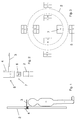
- Fig. 1 shows a side view of a length measuring device, which may be attached to a wall, for example.
- the length measuring device has a hollow profile 2 as a linear guide, on the outside slidably a caliper 4 is mounted, which carries a top plate 3. The caliper 4 is lowered so far until the top plate 3 rests on top of the head of the person to be measured.
- an inner slider 6 is slidably mounted (see Fig.2 ).
- the inner slide 6 is disc-shaped in cross section or, as shown here, provided with a closed lower end wall, so that the inner slide 6 covers the cross section of the hollow profile 2.
- the outer dimensions of the inner slider 6 are at the inner Adjusted dimensions of the hollow section 2, so that the inner slider 6 with the least possible play, but slidably seated in the interior of the hollow section 2.
- the inner dimensions of the caliper 4 are adapted to the outer dimensions of the hollow section 2, so that the caliper 4 is mounted with the least possible play, but slidably on the outer circumference of the hollow section 2.
- Fig. 3 shows a cross section through the hollow profile 2 in the range of the caliper and the inner slider, wherein the caliper and the inner slider component itself are not shown, but only the magnet assembly of a plurality of permanent magnets, which are incorporated in the inner slide and caliper.
- the inner slide 6 four permanent magnets 7 are distributed around the circumference introduced, which are distributed at a distance of 90 ° to each other around the circumference.
- four permanent magnets 5 are also placed in the caliper 4, which are arranged distributed at appropriate intervals of 90 ° to the outer caliper.
- the arrangement of the permanent magnets is such that opposing permanent magnets 5 and 7 of the caliper 4 and the inner slider 6 are aligned with opposite poles to each other.
- this is achieved in that the permanent magnets 7 of the inner slider are aligned with a magnetic pole, in this example with the north pole, to the outside, while the permanent magnets 5 are also arranged with this magnetic pole, here the north pole, directed outwards are, so that each face a pair of permanent magnets 5 and 7 with opposite poles facing each other.
- the caliper 4 and the inner slider 6 are magnetically coupled together.
- the inner slider 6 follows every movement of the caliper 4 along the hollow profile 2 Fig. 2 only one of the permanent magnets 5 and 7 is shown in each case.
- more or fewer than four permanent magnets per slider component may be provided, e.g. only one permanent magnet in the caliper 4 and the inner slider 6. It is even possible that even only one magnet is provided either in the inner slider 6 or in the caliper 4 and the other slider component without its own magnet contains ferro- or paramagnetic material so that a magnetic attraction between the inner slider 6 and the caliper 4 is effected.
- the one or more magnets of the magnet assembly are preferably permanent magnets, but in principle also electromagnets can be used.
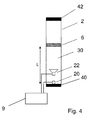
- Fig. 4 shows a schematic longitudinal sectional view of a hollow section 2 of a length measuring device.
- the inner slider 6 is simply disk-shaped and covers the cross section of the hollow section 2 from.
- the hollow profile 2 is provided at the lower end with a closed end wall 40, so that between the end wall 40 and the inner slide 6, a closed space is formed in the hollow profile, which can be considered as an acoustic resonator.
- the measuring device for determining the position of the inner slide 6 along the longitudinal direction of the hollow profile 2 includes a loudspeaker 22 and a microphone 20, which are arranged in the interior of the acoustic resonator 30.
- the speaker 22 and the microphone 20 are connected to a control and evaluation unit 9, which is shown here arranged in the outer space of the hollow profile, but which can also be accommodated in the interior of the hollow profile.
- the control and evaluation unit 9 is a programmable data processing device which is adapted to excite the loudspeaker 22 for emitting an acoustic impulse and to record the resulting impulse response of the acoustic resonator 30 by recording the signal of the microphone 20.
- the control and evaluation unit 9 is further adapted to determine the fundamental frequency f 0 of the resonator from the acoustic impulse response.
- This fundamental frequency f 0 has a wavelength ⁇ 0 equal to twice the length of the acoustic resonator (the simplest standing wave in the acoustic resonator 30 is a half-wave each having a velocity node on the end wall 40 and on the reflective wall of the inner slider 6).
- a wideband excitation by an acoustic pulse higher modes are excited in the acoustic resonator 30 in addition to the fundamental frequency, whose wavelengths are integer multiples of ⁇ 0/2. These modes, as will be shown later, may be additional to the measurement process.
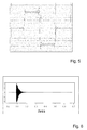
- Fig. 5 shows the time dependence of an excitation signal generated by the control and evaluation unit 9 for the speaker 22 for emitting an acoustic pulse.
- This signal preferably consists of a positive and negative half-wave with a substantially rectangular shape.
- the excitation signal does not have an ideal rectangular shape (which in principle would have an unlimited frequency spectrum) because the bandwidth of the pulse is limited.
- the bandwidth of the pulse should be chosen so that the smallest included wavelength is greater than twice the diameter of the hollow profile. This ensures, as already mentioned above, that the sound propagates in the hollow profile as a plane wave.
- the time length of a half-wave of the excitation signal should be greater as the period of the signal with the lowest frequency to be evaluated.
- Fig. 6 shows the time course of the recorded with the microphone 20 impulse response of the acoustic resonator.
- the acoustic impulse response Fig. 6 into a frequency spectrum to determine the fundamental frequency f 0 in the frequency spectrum.
- the transformation into a frequency spectrum is carried out by a Fourier transformation. Possible methods of digital signal processing for Fourier transformation are, for example, the discrete Fourier transformation (DFT) or the fast Fourier transformation (FFT), for the execution of which the control and evaluation unit 9 can be set up.
- DFT discrete Fourier transformation
- FFT fast Fourier transformation
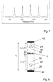
- Fig. 7 now shows a section of the frequency spectrum of the impulse response.
- local maxima which arise from the excited eigenmodes, can be clearly recognized. These occur at integer multiples of the fundamental frequency f 0 .
- the fundamental frequency can thus also be determined via the distances of adjacent modes in the frequency spectrum.
- This procedure has the advantage that the lower limit frequency of the loudspeaker used can be selected to be greater than the actual fundamental frequency f 0 of the acoustic resonator to be determined.
- the lower limit frequency of a loudspeaker is determined inter alia by the size of its membrane. The larger this is, the lower the cutoff frequency can be. Since the speaker is placed inside the hollow profile, the smallest possible membrane diameter is sought.
- the simplest standing wave in the acoustic resonator can not be easily observed with the present method, since the loudspeaker can not adequately generate the large wavelength required for this purpose.
- This effect is also in Fig. 7 to recognize, from which results the fundamental frequency is slightly more than 300 Hz (intervals of successive maxima). At slightly more than 300 Hz is in the in Fig. 7 However, for the reason given at the fundamental frequency of slightly more than 300 Hz, no usable maximum can be recognized.
Landscapes
- Health & Medical Sciences (AREA)
- Life Sciences & Earth Sciences (AREA)
- Physics & Mathematics (AREA)
- Engineering & Computer Science (AREA)
- Animal Behavior & Ethology (AREA)
- Public Health (AREA)
- Veterinary Medicine (AREA)
- General Health & Medical Sciences (AREA)
- General Physics & Mathematics (AREA)
- Surgery (AREA)
- Molecular Biology (AREA)
- Biophysics (AREA)
- Pathology (AREA)
- Biomedical Technology (AREA)
- Heart & Thoracic Surgery (AREA)
- Medical Informatics (AREA)
- Dentistry (AREA)
- Oral & Maxillofacial Surgery (AREA)
- Mathematical Physics (AREA)
- Signal Processing (AREA)
- Psychiatry (AREA)
- Physiology (AREA)
- Artificial Intelligence (AREA)
- Computer Vision & Pattern Recognition (AREA)
- Length Measuring Devices Characterised By Use Of Acoustic Means (AREA)
- Measurement Of Mechanical Vibrations Or Ultrasonic Waves (AREA)
- Length Measuring Devices With Unspecified Measuring Means (AREA)
Applications Claiming Priority (2)
| Application Number | Priority Date | Filing Date | Title |
|---|---|---|---|
| DE102012220468.7A DE102012220468B3 (de) | 2012-11-09 | 2012-11-09 | Längenmessgerät |
| PCT/EP2013/067022 WO2014072089A1 (de) | 2012-11-09 | 2013-08-14 | Längenmessgerät |
Publications (2)
| Publication Number | Publication Date |
|---|---|
| EP2916733A1 EP2916733A1 (de) | 2015-09-16 |
| EP2916733B1 true EP2916733B1 (de) | 2016-10-26 |
Family
ID=48986130
Family Applications (1)
| Application Number | Title | Priority Date | Filing Date |
|---|---|---|---|
| EP13750048.4A Active EP2916733B1 (de) | 2012-11-09 | 2013-08-14 | Längenmessgerät |
Country Status (8)
| Country | Link |
|---|---|
| US (1) | US10143402B2 (enExample) |
| EP (1) | EP2916733B1 (enExample) |
| JP (1) | JP6139692B2 (enExample) |
| CN (1) | CN104755028B (enExample) |
| BR (1) | BR112015010615A2 (enExample) |
| DE (1) | DE102012220468B3 (enExample) |
| ES (1) | ES2610403T3 (enExample) |
| WO (1) | WO2014072089A1 (enExample) |
Families Citing this family (6)
| Publication number | Priority date | Publication date | Assignee | Title |
|---|---|---|---|---|
| DE102012220412B3 (de) * | 2012-11-28 | 2014-03-27 | Seca Ag | Längenmessgerät |
| JP7475621B2 (ja) * | 2018-08-31 | 2024-04-30 | 株式会社タニタ | 長さ測定装置、長さ測定方法、プログラム、及び身長計 |
| US11946797B2 (en) * | 2022-08-02 | 2024-04-02 | Arnold Chase | Visual sonic conduit locator |
| US11722227B1 (en) * | 2022-08-02 | 2023-08-08 | Arnold Chase | Sonic conduit tracer system |
| US20240361278A1 (en) * | 2023-04-27 | 2024-10-31 | X-wave Innovations, Inc. | Ultrasonic waveguide sensor and apparatus for distributed physical parameter measurements |
| WO2025034815A1 (en) * | 2023-08-07 | 2025-02-13 | Chase Arnold | Visual sonic conduit locator |
Family Cites Families (24)
| Publication number | Priority date | Publication date | Assignee | Title |
|---|---|---|---|---|
| JPS5972013A (ja) * | 1982-10-18 | 1984-04-23 | Asahi Kosan Kk | 埋設配管測長方法 |
| JPS5882110A (ja) * | 1982-10-25 | 1983-05-17 | Yokogawa Hokushin Electric Corp | 身長測定装置 |
| US4543649A (en) * | 1983-10-17 | 1985-09-24 | Teknar, Inc. | System for ultrasonically detecting the relative position of a moveable device |
| DE3428132A1 (de) * | 1984-07-31 | 1985-06-13 | TC Technologie Consulting Institut für angewandte Forschung GmbH, 8000 München | Verfahren zur messung von fluessigkeitshoehen in behaeltern |
| DE3513848A1 (de) | 1985-04-17 | 1986-10-23 | Quante Fernmeldetechnik GmbH, 5600 Wuppertal | Schaltung zur ueberwachung der isolationswiderstaende einer schar von baugruppen einer elektrischen anlage mit gemeinsamer erdfreier stromversorgung, insbesondere einer fernmelde- oder signaltechnischen einrichtung |
| US4913157A (en) * | 1986-06-03 | 1990-04-03 | Analog Devices, Inc. | Ultrasound method and apparatus for evaluating, in vivo, bone conditions |
| GB8823391D0 (en) * | 1988-10-05 | 1988-11-09 | Geotechnical Instr Uk Ltd | Measuring liquid level |
| AT397430B (de) * | 1989-10-16 | 1994-04-25 | Hrdlicka Armin W Ing | Vorrichtung zur längenbestimmung |
| JPH02239843A (ja) | 1989-03-13 | 1990-09-21 | Omron Tateisi Electron Co | 身長計測装置 |
| JPH05332757A (ja) * | 1992-06-01 | 1993-12-14 | Nippon Telegr & Teleph Corp <Ntt> | 管路長計測装置 |
| CN2171850Y (zh) * | 1992-09-09 | 1994-07-13 | 陈献聪 | 身高体重测量器 |
| AT401109B (de) | 1993-07-01 | 1996-06-25 | Forschungsgesellschaft Joanneu | Verfahren zur tastlosen längenmessung |
| CA2169307C (en) * | 1994-12-12 | 2003-10-14 | David A. Hutchins | Non-contact characterization and inspection of materials using wideband air coupled ultrasound |
| WO1998017974A1 (en) * | 1996-10-18 | 1998-04-30 | Data Instruments, Inc. | Position sensor with magnetic coupling |
| RU2127873C1 (ru) | 1997-09-15 | 1999-03-20 | Николай Иванович Балин | Ультразвуковой датчик уровня жидкости |
| US6982929B2 (en) * | 2001-12-04 | 2006-01-03 | Disney Enterprises, Inc. | Height measurement method and apparatus |
| JP2004061473A (ja) * | 2002-06-03 | 2004-02-26 | Shogo Tanaka | 地下水位測定方法及びその装置 |
| JP2004061362A (ja) | 2002-07-30 | 2004-02-26 | Mitsutoyo Corp | 測長用ハンドツール |
| JP4256309B2 (ja) * | 2003-09-29 | 2009-04-22 | 株式会社東芝 | 超音波プローブおよび超音波診断装置 |
| CN1883396A (zh) * | 2006-06-26 | 2006-12-27 | 王秀丽 | 超声波二维人体测量仪及其测量方法 |
| CN100434043C (zh) * | 2007-01-10 | 2008-11-19 | 陈菊萍 | 超声波身高测量装置 |
| JP5080166B2 (ja) | 2007-08-10 | 2012-11-21 | 日立情報通信エンジニアリング株式会社 | 管長測定システム及びその測定方法 |
| DE102010001886A1 (de) * | 2010-02-12 | 2011-08-18 | Technische Universität Graz | Messung der Länge eines Hohlraums, insbesondere Rohres |
| US9592345B2 (en) * | 2012-07-11 | 2017-03-14 | Sanofi-Aventis Deutschland Gmbh | Arrangement and method for determining a stopper position |
-
2012
- 2012-11-09 DE DE102012220468.7A patent/DE102012220468B3/de not_active Expired - Fee Related
-
2013
- 2013-08-14 ES ES13750048.4T patent/ES2610403T3/es active Active
- 2013-08-14 CN CN201380057386.3A patent/CN104755028B/zh active Active
- 2013-08-14 EP EP13750048.4A patent/EP2916733B1/de active Active
- 2013-08-14 JP JP2015541041A patent/JP6139692B2/ja active Active
- 2013-08-14 US US14/441,802 patent/US10143402B2/en active Active
- 2013-08-14 WO PCT/EP2013/067022 patent/WO2014072089A1/de not_active Ceased
- 2013-08-14 BR BR112015010615A patent/BR112015010615A2/pt not_active IP Right Cessation
Non-Patent Citations (1)
| Title |
|---|
| None * |
Also Published As
| Publication number | Publication date |
|---|---|
| US20160242676A1 (en) | 2016-08-25 |
| ES2610403T3 (es) | 2017-04-27 |
| JP6139692B2 (ja) | 2017-05-31 |
| US10143402B2 (en) | 2018-12-04 |
| DE102012220468B3 (de) | 2014-03-27 |
| BR112015010615A2 (pt) | 2017-08-22 |
| CN104755028A (zh) | 2015-07-01 |
| CN104755028B (zh) | 2017-03-08 |
| EP2916733A1 (de) | 2015-09-16 |
| JP2015535594A (ja) | 2015-12-14 |
| WO2014072089A1 (de) | 2014-05-15 |
Similar Documents
| Publication | Publication Date | Title |
|---|---|---|
| EP2925225B1 (de) | Längenmessgerät | |
| EP2916733B1 (de) | Längenmessgerät | |
| EP0271670A1 (de) | Verfahren zur Detektion von Korrosion oder dergleichen | |
| EP3563117A1 (de) | Sensoreinrichtung | |
| DE102011012601A1 (de) | Kraftmesssystem, Verfahren zum Erfassen von Kräften und Momenten an einem rotierenden Körper und Windkanal mit einem darin angeordneten und zumindest einen Propeller aufweisenden Modell mit einem Kraftmesssystem | |
| WO2006007807A1 (de) | Verfahren und vorrichtung zur zerstörungsfreien prüfung von rohren | |
| EP1728102B1 (de) | Ortungsgerät mit ausgabeeinheit zur wiedergabe einer ausgabegrösse | |
| DE2421675A1 (de) | Stroemungsmesser fuer fluida mit raeumlich zufaellig verteilten, mitgefuehrten markierungen | |
| WO2011135063A2 (de) | Magnetisches längenmesssystem, längenmessverfahren sowie herstellungsverfahren eines magnetischen längenmesssystems | |
| DE102014213972B4 (de) | Vorrichtung und Verfahren zur Bestimmung von Rissparametern | |
| EP0100009A1 (de) | Vorrichtung zum zerstörungsfreien Messen der Einhärtetiefe von Werkstoffen | |
| DE4113952C2 (de) | Verfahren und Vorrichtung zum Vorhersagen von Erdbeben | |
| DE4004171A1 (de) | Vorrichtung zur beruehrungslosen erfassung eines rissstarts bei einer bruchmechanikprobe | |
| DE1303674C2 (de) | Magnetischer schichtdickenmesser | |
| DE102011001746A1 (de) | Prüfkörper sowie Verfahren zum Einmessen eines Koordinatenmessgerätes | |
| DE102013103445A1 (de) | Magnetischer Linear- oder Drehgeber | |
| EP3002583A1 (de) | Wirbelstromprüfung mit impulsmagnetisierung | |
| DE102012002127B3 (de) | Verfahren und Vorrichtung zur Erkennung von Oberflächenrissen | |
| DE102004023313A1 (de) | Magnetischer Impulsgeber aus Gummi | |
| DE2839566A1 (de) | Verfahren und vorrichtung zum bestimmen von eigenschaften von erdformationen | |
| DE1248956B (enExample) | ||
| DE102004025387B4 (de) | Magnetostriktive Wegaufnehmervorrichtung | |
| DE102008020765A1 (de) | Messanordnung und Verfahren zum berührungslosen Ermitteln physikalischer Eigenschaften | |
| DE202014104374U1 (de) | Mehrkanalprüfkopf und Prüfanlage zur magnetischen Streuflussmessung | |
| DE3818875C2 (de) | Vorrichtung zum Bestimmen der Masse bei vorbestimmter Geschwindigkeit, der Geschwindigkeit bei vorbestimmter Masse sowie der Anzahl von Partikeln in einem Fluid |
Legal Events
| Date | Code | Title | Description |
|---|---|---|---|
| PUAI | Public reference made under article 153(3) epc to a published international application that has entered the european phase |
Free format text: ORIGINAL CODE: 0009012 |
|
| 17P | Request for examination filed |
Effective date: 20150226 |
|
| AK | Designated contracting states |
Kind code of ref document: A1 Designated state(s): AL AT BE BG CH CY CZ DE DK EE ES FI FR GB GR HR HU IE IS IT LI LT LU LV MC MK MT NL NO PL PT RO RS SE SI SK SM TR |
|
| AX | Request for extension of the european patent |
Extension state: BA ME |
|
| DAX | Request for extension of the european patent (deleted) | ||
| GRAP | Despatch of communication of intention to grant a patent |
Free format text: ORIGINAL CODE: EPIDOSNIGR1 |
|
| INTG | Intention to grant announced |
Effective date: 20160725 |
|
| GRAS | Grant fee paid |
Free format text: ORIGINAL CODE: EPIDOSNIGR3 |
|
| GRAA | (expected) grant |
Free format text: ORIGINAL CODE: 0009210 |
|
| AK | Designated contracting states |
Kind code of ref document: B1 Designated state(s): AL AT BE BG CH CY CZ DE DK EE ES FI FR GB GR HR HU IE IS IT LI LT LU LV MC MK MT NL NO PL PT RO RS SE SI SK SM TR |
|
| REG | Reference to a national code |
Ref country code: GB Ref legal event code: FG4D Free format text: NOT ENGLISH |
|
| REG | Reference to a national code |
Ref country code: CH Ref legal event code: EP |
|
| REG | Reference to a national code |
Ref country code: AT Ref legal event code: REF Ref document number: 839391 Country of ref document: AT Kind code of ref document: T Effective date: 20161115 |
|
| REG | Reference to a national code |
Ref country code: IE Ref legal event code: FG4D Free format text: LANGUAGE OF EP DOCUMENT: GERMAN |
|
| REG | Reference to a national code |
Ref country code: DE Ref legal event code: R096 Ref document number: 502013005121 Country of ref document: DE |
|
| REG | Reference to a national code |
Ref country code: LT Ref legal event code: MG4D |
|
| PG25 | Lapsed in a contracting state [announced via postgrant information from national office to epo] |
Ref country code: LV Free format text: LAPSE BECAUSE OF FAILURE TO SUBMIT A TRANSLATION OF THE DESCRIPTION OR TO PAY THE FEE WITHIN THE PRESCRIBED TIME-LIMIT Effective date: 20161026 |
|
| REG | Reference to a national code |
Ref country code: NL Ref legal event code: MP Effective date: 20161026 |
|
| REG | Reference to a national code |
Ref country code: ES Ref legal event code: FG2A Ref document number: 2610403 Country of ref document: ES Kind code of ref document: T3 Effective date: 20170427 |
|
| PG25 | Lapsed in a contracting state [announced via postgrant information from national office to epo] |
Ref country code: LT Free format text: LAPSE BECAUSE OF FAILURE TO SUBMIT A TRANSLATION OF THE DESCRIPTION OR TO PAY THE FEE WITHIN THE PRESCRIBED TIME-LIMIT Effective date: 20161026 Ref country code: NO Free format text: LAPSE BECAUSE OF FAILURE TO SUBMIT A TRANSLATION OF THE DESCRIPTION OR TO PAY THE FEE WITHIN THE PRESCRIBED TIME-LIMIT Effective date: 20170126 Ref country code: GR Free format text: LAPSE BECAUSE OF FAILURE TO SUBMIT A TRANSLATION OF THE DESCRIPTION OR TO PAY THE FEE WITHIN THE PRESCRIBED TIME-LIMIT Effective date: 20170127 Ref country code: SE Free format text: LAPSE BECAUSE OF FAILURE TO SUBMIT A TRANSLATION OF THE DESCRIPTION OR TO PAY THE FEE WITHIN THE PRESCRIBED TIME-LIMIT Effective date: 20161026 |
|
| PG25 | Lapsed in a contracting state [announced via postgrant information from national office to epo] |
Ref country code: IS Free format text: LAPSE BECAUSE OF FAILURE TO SUBMIT A TRANSLATION OF THE DESCRIPTION OR TO PAY THE FEE WITHIN THE PRESCRIBED TIME-LIMIT Effective date: 20170226 Ref country code: NL Free format text: LAPSE BECAUSE OF FAILURE TO SUBMIT A TRANSLATION OF THE DESCRIPTION OR TO PAY THE FEE WITHIN THE PRESCRIBED TIME-LIMIT Effective date: 20161026 Ref country code: HR Free format text: LAPSE BECAUSE OF FAILURE TO SUBMIT A TRANSLATION OF THE DESCRIPTION OR TO PAY THE FEE WITHIN THE PRESCRIBED TIME-LIMIT Effective date: 20161026 Ref country code: PL Free format text: LAPSE BECAUSE OF FAILURE TO SUBMIT A TRANSLATION OF THE DESCRIPTION OR TO PAY THE FEE WITHIN THE PRESCRIBED TIME-LIMIT Effective date: 20161026 Ref country code: FI Free format text: LAPSE BECAUSE OF FAILURE TO SUBMIT A TRANSLATION OF THE DESCRIPTION OR TO PAY THE FEE WITHIN THE PRESCRIBED TIME-LIMIT Effective date: 20161026 Ref country code: PT Free format text: LAPSE BECAUSE OF FAILURE TO SUBMIT A TRANSLATION OF THE DESCRIPTION OR TO PAY THE FEE WITHIN THE PRESCRIBED TIME-LIMIT Effective date: 20170227 Ref country code: RS Free format text: LAPSE BECAUSE OF FAILURE TO SUBMIT A TRANSLATION OF THE DESCRIPTION OR TO PAY THE FEE WITHIN THE PRESCRIBED TIME-LIMIT Effective date: 20161026 |
|
| REG | Reference to a national code |
Ref country code: FR Ref legal event code: PLFP Year of fee payment: 5 |
|
| REG | Reference to a national code |
Ref country code: DE Ref legal event code: R097 Ref document number: 502013005121 Country of ref document: DE |
|
| PG25 | Lapsed in a contracting state [announced via postgrant information from national office to epo] |
Ref country code: RO Free format text: LAPSE BECAUSE OF FAILURE TO SUBMIT A TRANSLATION OF THE DESCRIPTION OR TO PAY THE FEE WITHIN THE PRESCRIBED TIME-LIMIT Effective date: 20161026 Ref country code: SK Free format text: LAPSE BECAUSE OF FAILURE TO SUBMIT A TRANSLATION OF THE DESCRIPTION OR TO PAY THE FEE WITHIN THE PRESCRIBED TIME-LIMIT Effective date: 20161026 Ref country code: CZ Free format text: LAPSE BECAUSE OF FAILURE TO SUBMIT A TRANSLATION OF THE DESCRIPTION OR TO PAY THE FEE WITHIN THE PRESCRIBED TIME-LIMIT Effective date: 20161026 Ref country code: EE Free format text: LAPSE BECAUSE OF FAILURE TO SUBMIT A TRANSLATION OF THE DESCRIPTION OR TO PAY THE FEE WITHIN THE PRESCRIBED TIME-LIMIT Effective date: 20161026 Ref country code: DK Free format text: LAPSE BECAUSE OF FAILURE TO SUBMIT A TRANSLATION OF THE DESCRIPTION OR TO PAY THE FEE WITHIN THE PRESCRIBED TIME-LIMIT Effective date: 20161026 |
|
| PG25 | Lapsed in a contracting state [announced via postgrant information from national office to epo] |
Ref country code: BG Free format text: LAPSE BECAUSE OF FAILURE TO SUBMIT A TRANSLATION OF THE DESCRIPTION OR TO PAY THE FEE WITHIN THE PRESCRIBED TIME-LIMIT Effective date: 20170126 Ref country code: SM Free format text: LAPSE BECAUSE OF FAILURE TO SUBMIT A TRANSLATION OF THE DESCRIPTION OR TO PAY THE FEE WITHIN THE PRESCRIBED TIME-LIMIT Effective date: 20161026 |
|
| PLBE | No opposition filed within time limit |
Free format text: ORIGINAL CODE: 0009261 |
|
| STAA | Information on the status of an ep patent application or granted ep patent |
Free format text: STATUS: NO OPPOSITION FILED WITHIN TIME LIMIT |
|
| 26N | No opposition filed |
Effective date: 20170727 |
|
| PG25 | Lapsed in a contracting state [announced via postgrant information from national office to epo] |
Ref country code: SI Free format text: LAPSE BECAUSE OF FAILURE TO SUBMIT A TRANSLATION OF THE DESCRIPTION OR TO PAY THE FEE WITHIN THE PRESCRIBED TIME-LIMIT Effective date: 20161026 |
|
| REG | Reference to a national code |
Ref country code: CH Ref legal event code: PL |
|
| PG25 | Lapsed in a contracting state [announced via postgrant information from national office to epo] |
Ref country code: MC Free format text: LAPSE BECAUSE OF FAILURE TO SUBMIT A TRANSLATION OF THE DESCRIPTION OR TO PAY THE FEE WITHIN THE PRESCRIBED TIME-LIMIT Effective date: 20161026 |
|
| PG25 | Lapsed in a contracting state [announced via postgrant information from national office to epo] |
Ref country code: CH Free format text: LAPSE BECAUSE OF NON-PAYMENT OF DUE FEES Effective date: 20170831 Ref country code: LI Free format text: LAPSE BECAUSE OF NON-PAYMENT OF DUE FEES Effective date: 20170831 |
|
| REG | Reference to a national code |
Ref country code: IE Ref legal event code: MM4A |
|
| REG | Reference to a national code |
Ref country code: BE Ref legal event code: MM Effective date: 20170831 |
|
| PG25 | Lapsed in a contracting state [announced via postgrant information from national office to epo] |
Ref country code: LU Free format text: LAPSE BECAUSE OF NON-PAYMENT OF DUE FEES Effective date: 20170814 |
|
| REG | Reference to a national code |
Ref country code: FR Ref legal event code: PLFP Year of fee payment: 6 |
|
| PG25 | Lapsed in a contracting state [announced via postgrant information from national office to epo] |
Ref country code: IE Free format text: LAPSE BECAUSE OF NON-PAYMENT OF DUE FEES Effective date: 20170814 |
|
| PG25 | Lapsed in a contracting state [announced via postgrant information from national office to epo] |
Ref country code: BE Free format text: LAPSE BECAUSE OF NON-PAYMENT OF DUE FEES Effective date: 20170831 |
|
| PG25 | Lapsed in a contracting state [announced via postgrant information from national office to epo] |
Ref country code: MT Free format text: LAPSE BECAUSE OF FAILURE TO SUBMIT A TRANSLATION OF THE DESCRIPTION OR TO PAY THE FEE WITHIN THE PRESCRIBED TIME-LIMIT Effective date: 20161026 |
|
| PG25 | Lapsed in a contracting state [announced via postgrant information from national office to epo] |
Ref country code: HU Free format text: LAPSE BECAUSE OF FAILURE TO SUBMIT A TRANSLATION OF THE DESCRIPTION OR TO PAY THE FEE WITHIN THE PRESCRIBED TIME-LIMIT; INVALID AB INITIO Effective date: 20130814 |
|
| REG | Reference to a national code |
Ref country code: AT Ref legal event code: MM01 Ref document number: 839391 Country of ref document: AT Kind code of ref document: T Effective date: 20180814 |
|
| PG25 | Lapsed in a contracting state [announced via postgrant information from national office to epo] |
Ref country code: CY Free format text: LAPSE BECAUSE OF FAILURE TO SUBMIT A TRANSLATION OF THE DESCRIPTION OR TO PAY THE FEE WITHIN THE PRESCRIBED TIME-LIMIT Effective date: 20161026 |
|
| PG25 | Lapsed in a contracting state [announced via postgrant information from national office to epo] |
Ref country code: MK Free format text: LAPSE BECAUSE OF FAILURE TO SUBMIT A TRANSLATION OF THE DESCRIPTION OR TO PAY THE FEE WITHIN THE PRESCRIBED TIME-LIMIT Effective date: 20161026 |
|
| PG25 | Lapsed in a contracting state [announced via postgrant information from national office to epo] |
Ref country code: AT Free format text: LAPSE BECAUSE OF NON-PAYMENT OF DUE FEES Effective date: 20180814 |
|
| PG25 | Lapsed in a contracting state [announced via postgrant information from national office to epo] |
Ref country code: TR Free format text: LAPSE BECAUSE OF FAILURE TO SUBMIT A TRANSLATION OF THE DESCRIPTION OR TO PAY THE FEE WITHIN THE PRESCRIBED TIME-LIMIT Effective date: 20161026 |
|
| PG25 | Lapsed in a contracting state [announced via postgrant information from national office to epo] |
Ref country code: AL Free format text: LAPSE BECAUSE OF FAILURE TO SUBMIT A TRANSLATION OF THE DESCRIPTION OR TO PAY THE FEE WITHIN THE PRESCRIBED TIME-LIMIT Effective date: 20161026 |
|
| PGFP | Annual fee paid to national office [announced via postgrant information from national office to epo] |
Ref country code: FR Payment date: 20240814 Year of fee payment: 12 |
|
| PGFP | Annual fee paid to national office [announced via postgrant information from national office to epo] |
Ref country code: ES Payment date: 20240918 Year of fee payment: 12 |
|
| PGFP | Annual fee paid to national office [announced via postgrant information from national office to epo] |
Ref country code: IT Payment date: 20240830 Year of fee payment: 12 |
|
| PGFP | Annual fee paid to national office [announced via postgrant information from national office to epo] |
Ref country code: DE Payment date: 20250819 Year of fee payment: 13 |
|
| PGFP | Annual fee paid to national office [announced via postgrant information from national office to epo] |
Ref country code: GB Payment date: 20250822 Year of fee payment: 13 |