EP2915591B1 - Sauerstoffsensor mit poröser keramikbeschichtung darauf und verfahren zur herstellung einern porösen keramikbeschichtung - Google Patents
Sauerstoffsensor mit poröser keramikbeschichtung darauf und verfahren zur herstellung einern porösen keramikbeschichtung Download PDFInfo
- Publication number
- EP2915591B1 EP2915591B1 EP13851491.4A EP13851491A EP2915591B1 EP 2915591 B1 EP2915591 B1 EP 2915591B1 EP 13851491 A EP13851491 A EP 13851491A EP 2915591 B1 EP2915591 B1 EP 2915591B1
- Authority
- EP
- European Patent Office
- Prior art keywords
- coating layer
- ceramic coating
- porous ceramic
- oxygen sensor
- forming
- Prior art date
- Legal status (The legal status is an assumption and is not a legal conclusion. Google has not performed a legal analysis and makes no representation as to the accuracy of the status listed.)
- Not-in-force
Links
Images


Classifications
-
- G—PHYSICS
- G01—MEASURING; TESTING
- G01N—INVESTIGATING OR ANALYSING MATERIALS BY DETERMINING THEIR CHEMICAL OR PHYSICAL PROPERTIES
- G01N33/00—Investigating or analysing materials by specific methods not covered by groups G01N1/00 - G01N31/00
- G01N33/0004—Gaseous mixtures, e.g. polluted air
- G01N33/0009—General constructional details of gas analysers, e.g. portable test equipment
- G01N33/0027—General constructional details of gas analysers, e.g. portable test equipment concerning the detector
- G01N33/0036—General constructional details of gas analysers, e.g. portable test equipment concerning the detector specially adapted to detect a particular component
-
- B—PERFORMING OPERATIONS; TRANSPORTING
- B05—SPRAYING OR ATOMISING IN GENERAL; APPLYING FLUENT MATERIALS TO SURFACES, IN GENERAL
- B05B—SPRAYING APPARATUS; ATOMISING APPARATUS; NOZZLES
- B05B17/00—Apparatus for spraying or atomising liquids or other fluent materials, not covered by the preceding groups
- B05B17/04—Apparatus for spraying or atomising liquids or other fluent materials, not covered by the preceding groups operating with special methods
-
- B—PERFORMING OPERATIONS; TRANSPORTING
- B05—SPRAYING OR ATOMISING IN GENERAL; APPLYING FLUENT MATERIALS TO SURFACES, IN GENERAL
- B05B—SPRAYING APPARATUS; ATOMISING APPARATUS; NOZZLES
- B05B7/00—Spraying apparatus for discharge of liquids or other fluent materials from two or more sources, e.g. of liquid and air, of powder and gas
- B05B7/16—Spraying apparatus for discharge of liquids or other fluent materials from two or more sources, e.g. of liquid and air, of powder and gas incorporating means for heating or cooling the material to be sprayed
- B05B7/22—Spraying apparatus for discharge of liquids or other fluent materials from two or more sources, e.g. of liquid and air, of powder and gas incorporating means for heating or cooling the material to be sprayed electrically, magnetically or electromagnetically, e.g. by arc
- B05B7/222—Spraying apparatus for discharge of liquids or other fluent materials from two or more sources, e.g. of liquid and air, of powder and gas incorporating means for heating or cooling the material to be sprayed electrically, magnetically or electromagnetically, e.g. by arc using an arc
-
- C—CHEMISTRY; METALLURGY
- C23—COATING METALLIC MATERIAL; COATING MATERIAL WITH METALLIC MATERIAL; CHEMICAL SURFACE TREATMENT; DIFFUSION TREATMENT OF METALLIC MATERIAL; COATING BY VACUUM EVAPORATION, BY SPUTTERING, BY ION IMPLANTATION OR BY CHEMICAL VAPOUR DEPOSITION, IN GENERAL; INHIBITING CORROSION OF METALLIC MATERIAL OR INCRUSTATION IN GENERAL
- C23C—COATING METALLIC MATERIAL; COATING MATERIAL WITH METALLIC MATERIAL; SURFACE TREATMENT OF METALLIC MATERIAL BY DIFFUSION INTO THE SURFACE, BY CHEMICAL CONVERSION OR SUBSTITUTION; COATING BY VACUUM EVAPORATION, BY SPUTTERING, BY ION IMPLANTATION OR BY CHEMICAL VAPOUR DEPOSITION, IN GENERAL
- C23C16/00—Chemical coating by decomposition of gaseous compounds, without leaving reaction products of surface material in the coating, i.e. chemical vapour deposition [CVD] processes
- C23C16/44—Chemical coating by decomposition of gaseous compounds, without leaving reaction products of surface material in the coating, i.e. chemical vapour deposition [CVD] processes characterised by the method of coating
- C23C16/50—Chemical coating by decomposition of gaseous compounds, without leaving reaction products of surface material in the coating, i.e. chemical vapour deposition [CVD] processes characterised by the method of coating using electric discharges
-
- C—CHEMISTRY; METALLURGY
- C23—COATING METALLIC MATERIAL; COATING MATERIAL WITH METALLIC MATERIAL; CHEMICAL SURFACE TREATMENT; DIFFUSION TREATMENT OF METALLIC MATERIAL; COATING BY VACUUM EVAPORATION, BY SPUTTERING, BY ION IMPLANTATION OR BY CHEMICAL VAPOUR DEPOSITION, IN GENERAL; INHIBITING CORROSION OF METALLIC MATERIAL OR INCRUSTATION IN GENERAL
- C23C—COATING METALLIC MATERIAL; COATING MATERIAL WITH METALLIC MATERIAL; SURFACE TREATMENT OF METALLIC MATERIAL BY DIFFUSION INTO THE SURFACE, BY CHEMICAL CONVERSION OR SUBSTITUTION; COATING BY VACUUM EVAPORATION, BY SPUTTERING, BY ION IMPLANTATION OR BY CHEMICAL VAPOUR DEPOSITION, IN GENERAL
- C23C4/00—Coating by spraying the coating material in the molten state, e.g. by flame, plasma or electric discharge
- C23C4/02—Pretreatment of the material to be coated, e.g. for coating on selected surface areas
-
- C—CHEMISTRY; METALLURGY
- C23—COATING METALLIC MATERIAL; COATING MATERIAL WITH METALLIC MATERIAL; CHEMICAL SURFACE TREATMENT; DIFFUSION TREATMENT OF METALLIC MATERIAL; COATING BY VACUUM EVAPORATION, BY SPUTTERING, BY ION IMPLANTATION OR BY CHEMICAL VAPOUR DEPOSITION, IN GENERAL; INHIBITING CORROSION OF METALLIC MATERIAL OR INCRUSTATION IN GENERAL
- C23C—COATING METALLIC MATERIAL; COATING MATERIAL WITH METALLIC MATERIAL; SURFACE TREATMENT OF METALLIC MATERIAL BY DIFFUSION INTO THE SURFACE, BY CHEMICAL CONVERSION OR SUBSTITUTION; COATING BY VACUUM EVAPORATION, BY SPUTTERING, BY ION IMPLANTATION OR BY CHEMICAL VAPOUR DEPOSITION, IN GENERAL
- C23C4/00—Coating by spraying the coating material in the molten state, e.g. by flame, plasma or electric discharge
- C23C4/04—Coating by spraying the coating material in the molten state, e.g. by flame, plasma or electric discharge characterised by the coating material
- C23C4/10—Oxides, borides, carbides, nitrides or silicides; Mixtures thereof
-
- C—CHEMISTRY; METALLURGY
- C23—COATING METALLIC MATERIAL; COATING MATERIAL WITH METALLIC MATERIAL; CHEMICAL SURFACE TREATMENT; DIFFUSION TREATMENT OF METALLIC MATERIAL; COATING BY VACUUM EVAPORATION, BY SPUTTERING, BY ION IMPLANTATION OR BY CHEMICAL VAPOUR DEPOSITION, IN GENERAL; INHIBITING CORROSION OF METALLIC MATERIAL OR INCRUSTATION IN GENERAL
- C23C—COATING METALLIC MATERIAL; COATING MATERIAL WITH METALLIC MATERIAL; SURFACE TREATMENT OF METALLIC MATERIAL BY DIFFUSION INTO THE SURFACE, BY CHEMICAL CONVERSION OR SUBSTITUTION; COATING BY VACUUM EVAPORATION, BY SPUTTERING, BY ION IMPLANTATION OR BY CHEMICAL VAPOUR DEPOSITION, IN GENERAL
- C23C4/00—Coating by spraying the coating material in the molten state, e.g. by flame, plasma or electric discharge
- C23C4/04—Coating by spraying the coating material in the molten state, e.g. by flame, plasma or electric discharge characterised by the coating material
- C23C4/10—Oxides, borides, carbides, nitrides or silicides; Mixtures thereof
- C23C4/11—Oxides
-
- C—CHEMISTRY; METALLURGY
- C23—COATING METALLIC MATERIAL; COATING MATERIAL WITH METALLIC MATERIAL; CHEMICAL SURFACE TREATMENT; DIFFUSION TREATMENT OF METALLIC MATERIAL; COATING BY VACUUM EVAPORATION, BY SPUTTERING, BY ION IMPLANTATION OR BY CHEMICAL VAPOUR DEPOSITION, IN GENERAL; INHIBITING CORROSION OF METALLIC MATERIAL OR INCRUSTATION IN GENERAL
- C23C—COATING METALLIC MATERIAL; COATING MATERIAL WITH METALLIC MATERIAL; SURFACE TREATMENT OF METALLIC MATERIAL BY DIFFUSION INTO THE SURFACE, BY CHEMICAL CONVERSION OR SUBSTITUTION; COATING BY VACUUM EVAPORATION, BY SPUTTERING, BY ION IMPLANTATION OR BY CHEMICAL VAPOUR DEPOSITION, IN GENERAL
- C23C4/00—Coating by spraying the coating material in the molten state, e.g. by flame, plasma or electric discharge
- C23C4/12—Coating by spraying the coating material in the molten state, e.g. by flame, plasma or electric discharge characterised by the method of spraying
- C23C4/134—Plasma spraying
-
- G—PHYSICS
- G01—MEASURING; TESTING
- G01N—INVESTIGATING OR ANALYSING MATERIALS BY DETERMINING THEIR CHEMICAL OR PHYSICAL PROPERTIES
- G01N27/00—Investigating or analysing materials by the use of electric, electrochemical, or magnetic means
- G01N27/26—Investigating or analysing materials by the use of electric, electrochemical, or magnetic means by investigating electrochemical variables; by using electrolysis or electrophoresis
- G01N27/403—Cells and electrode assemblies
- G01N27/406—Cells and probes with solid electrolytes
- G01N27/407—Cells and probes with solid electrolytes for investigating or analysing gases
-
- H—ELECTRICITY
- H05—ELECTRIC TECHNIQUES NOT OTHERWISE PROVIDED FOR
- H05H—PLASMA TECHNIQUE; PRODUCTION OF ACCELERATED ELECTRICALLY-CHARGED PARTICLES OR OF NEUTRONS; PRODUCTION OR ACCELERATION OF NEUTRAL MOLECULAR OR ATOMIC BEAMS
- H05H1/00—Generating plasma; Handling plasma
- H05H1/24—Generating plasma
Definitions
- an oxygen sensor is mounted at a predetermined position of an exhaust manifold and detects the concentration of oxygen included in exhaust gas to allow an engine control unit (ECU) to perform feedback for air-fuel ratio control (lambda value) using the detected oxygen concentration.
- ECU engine control unit
- Such an oxygen sensor is manufactured in consideration of temperature limit with respect to each part thereof. That is, the temperature limit for a header part thereof is set to about 650°C, the temperature limit for a grommet part thereof is set to about 200 °C, and the temperature limit for a tip part thereof is set to about 900 °C.
- the header part of the oxygen sensor Since the header part of the oxygen sensor is directly in contact with an exhaust manifold, it is closely related to the temperature of the surface of the exhaust manifold.
- the grommet part of the oxygen sensor is closely related to the temperature of the periphery of the exhaust manifold, the periphery being provided with the oxygen sensor.
- thermally-damaged parts include a main harness, a plastic head cover, a head cover gasket, etc., which are located near an exhaust manifold, in addition to an oxygen sensor.
- this method is problematic in that the heat protector inhibits air from smoothly flowing around the oxygen sensor, and thus the radiation heat of the exhaust manifold stays in the heat protector, thereby increasing the thermal damage of the oxygen sensor.
- Still another object of the present invention is to provide an oxygen sensor, wherein it is possible to prevent the sensing part of the oxygen sensor from being poisoned by harmful materials in exhaust gas, thus allowing the feedback of ECU to be smoothly performed by the oxygen sensor.
- an oxygen sensor coating apparatus which includes: a linear guide provided over the ground; a plasma gun connected to the guide and spraying a coating material containing ceramic powder onto an oxygen sensor as an object material using a plasma flame while moving straight along the guide; a reaction gas injector injecting reaction gas onto the object material while moving straight along the guide together with the plasma gun; and an object material fixing module provided opposite to the plasma gun and fixing the object material.
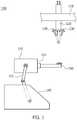
- the object material fixing module may include: a base frame which is supported on the ground; a connecting arm, one end of which is connected to the base frame; and a jig provided with a fixing bracket for fixing the object material and connected to the other end of the connecting arm to be rotated by driving the connecting arm.
- the coating material may be ceramic powder.
- the plurality of fixing brackets may be provided along one side of the jig.
- the fixing bracket may be rotatably provided on one side of the jig.
- the connecting arm may rotate the jig at predetermined angle intervals based on the end (serving as a rotation axis) of the object material fixed in the fixing bracket, and simultaneously plasma coating may be performed.
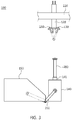
- the fixing bracket When the jig rotates at predetermined angle intervals to allow the fixing bracket to be flush with the plasma gun, the fixing bracket may not rotate, and the plasma gun may perform plasma coating once.
- the present invention provides a method of forming a porous ceramic coating layer on an oxygen sensor, including the steps of: fixing an oxygen sensor in any one of a plurality of fixing brackets provided along one side of a jig; spraying metal powder onto a sensing part of the oxygen sensor using a plasma gun and simultaneously injecting reaction gas onto the sensing part through a reaction gas injector to form an adhesion layer; injecting gas into the plasma gun provided with a positive electrode and a negative electrode through a gas inlet and then applying high voltage to the positive electrode and the negative electrode to generate a plasma flame; and spraying ceramic powder into the plasma flame through a powder inlet provided at the plasma gun to form a porous ceramic coating layer on the adhesion layer.
- the step of forming the porous ceramic coating layer may include the steps of: a) forming the porous ceramic coating layer on the adhesion layer while moving the plasma gun straight to the sensing part of the oxygen sensor fixed in the fixing bracket along one side of the jig; and b) repeatedly performing step a) while rotating the fixing bracket at predetermined angle intervals after step a).
- the adhesion layer may have a thickness of 0.1 to 10 ⁇ m.
- the porous ceramic coating layer may have a thickness of 200 to 500 ⁇ m.
- the ceramic coating layer may be immersed in a platinum (Pt) solution.
- the platinum (Pt) may be uniformly distributed in the ceramic coating layer in an amount of 0.3 to 5.0%.
- its sensing part is provided with a porous ceramic coating layer, thus preventing the sensing part from being damaged by the thermal shock from exhaust gas.
- the plasma gun 120 is provided therein with a positive electrode and a negative electrode, and high voltage is applied to the positive electrode and the negative electrode. Further, the plasma gun 120 is provided therein with a reaction gas injector 130 for injecting reaction gas. The plasma gun generates a plasma flame using the high voltage applied to the positive electrode and the negative electrode.
- Metal powder or ceramic powder, as a coating material is supplied to the plasma flame to perform plasma spray coating.
- the connecting arm 151 may consist of a plurality of joint links or an extensible or retractable cylinder, and may be operated to rotate the jig 140.
- a pair of connecting arms 151 be proved at both sides of the jig 140.
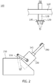
- a plurality of fixing brackets 141 are provided on one side of the jig 140 in the length direction of the jig 140. As shown in FIG. 2 , the fixing bracket 141 is rotatably provided.
- the ceramic coating layer 230 is immersed in a platinum (Pt) solution such that platinum is uniformly distributed in the ceramic coating layer 230 in an amount of 0.5 to 5.0%.
- the method of forming a porous ceramic coating layer 230 on an oxygen sensor 200 includes the steps of: fixing an oxygen sensor 200 in any one of a plurality of fixing brackets 141 provided along one side of a jig 140 (S100); spraying metal powder onto a sensing part 210 of the oxygen sensor 200 using a plasma gun 120 and simultaneously injecting reaction gas onto the sensing part 210 through a reaction gas injector 130 to form an adhesion layer 220 (S200); injecting gas into the plasma gun 120 provided with a positive electrode and a negative electrode through a gas inlet and then applying high voltage to the positive electrode and the negative electrode to generate a plasma flame (S300); and spraying ceramic powder into the plasma flame through a powder inlet provided at the plasma gun 120 to form a porous ceramic coating layer 230 on the adhesion layer 220 (S400).
- reaction gas a combination of oxide gas, nitride gas and carbide gas, more specifically, a combination of O 2 , O 3 , N 2 , H 2 and Ar
- reaction gas reacts with the sprayed metal powder, thus forming the adhesion layer 220 on the surface of the sensing part 210 of the oxygen sensor 200.
- the fixing bracket 141 rotates at 90° intervals to perform the plasma coating even on another side thereof (S320).
- the fixing bracket 141 rotates at 90° intervals to finally rotate to an angle of 360°, the fixing bracket 141 is further rotated or inclined at an angle of 45°, so the jig 140 is rotated to an angle of 90° based on the initial position thereof, and thus the rotation axis of the fixing bracket 141 is flush with the plasma gun 120 to allow the upper end of the oxygen sensor 200 to face the plasma gun 120.
Landscapes
- Chemical & Material Sciences (AREA)
- Engineering & Computer Science (AREA)
- Physics & Mathematics (AREA)
- Plasma & Fusion (AREA)
- Chemical Kinetics & Catalysis (AREA)
- Materials Engineering (AREA)
- Mechanical Engineering (AREA)
- Metallurgy (AREA)
- Organic Chemistry (AREA)
- Life Sciences & Earth Sciences (AREA)
- Health & Medical Sciences (AREA)
- Immunology (AREA)
- General Physics & Mathematics (AREA)
- Pathology (AREA)
- Analytical Chemistry (AREA)
- Biochemistry (AREA)
- General Health & Medical Sciences (AREA)
- Electromagnetism (AREA)
- Molecular Biology (AREA)
- Electrochemistry (AREA)
- Combustion & Propulsion (AREA)
- Food Science & Technology (AREA)
- Medicinal Chemistry (AREA)
- Spectroscopy & Molecular Physics (AREA)
- General Chemical & Material Sciences (AREA)
- Measuring Oxygen Concentration In Cells (AREA)
- Coating By Spraying Or Casting (AREA)
Claims (7)
- Verfahren zur Bildung einer porösen Keramikbeschichtung auf einem Sauerstoffsensor, dadurch gekennzeichnet, dass er die folgenden Schritte umfasst:(S100) Befestigung eines Sauerstoffsensors (200) in irgendeinem von mehreren Befestigungswinkeln (141), die entlang einer Seite einer Vorrichtung (140) angebracht sind;(S200) Aufsprühen von Metallpulver auf das Sensorteil des Sauerstoffsensors (200), unter Verwendung einer Plasma- Spritzpistole (120) und gleichzeitigem Einspeisen von Reaktionsgas durch einen Reaktionsgas - Injektor (130) auf das Sensorteil, um eine haftvermittelnde Schicht (220) zu bilden;(S300) Einspeisen von Gas in die Plasma- Spritzpistole (120), die mit einer positiven und einer negativen Elektrode versehen ist, durch einen Gaseinlass und dann Anlegen einer hohen Spannung an der positiven Elektrode und der negativen Elektrode, um eine Plasmaflamme zu erzeugen; und(S400) Sprühen von Keramikpulver durch einen Pulvereinlass, der an der Plasma-Spritzpistole (120) vorgesehen ist, in die Plasmaflamme, um eine poröse Keramikbeschichtung auf der haftvermittelnden Schicht (220) zu bilden.
- Verfahren nach Anspruch 1, worin der Schritt (S400) der Bildung der porösen Keramikbeschichtung die folgenden Schritte umfasst:a) Bildung des porösen Keramiküberzugs auf der haftvermittelnden Schicht (220), unter Bewegung der Plasma- Spritzpistole (120) gerade zum Sensorteil des Sauerstoffsensors (200), der in dem Befestigungswinkel (141) entlang einer Seite der Vorrichtung (140) angebracht ist; undb) wiederholtes Ausführen von Schritt a) unter Drehen des Befestigungswinkels (141) mit vorher festgelegten Winkelintervallen nach Schritt a).
- Verfahren nach Anspruch 2, worin der Schritt (S400) der Bildung der porösen Keramikbeschichtung weiterhin die folgenden Schritte umfasst:c) Drehen der Vorrichtung (140) mit vorher festgelegten Winkelintervallen, basierend auf dem Sensorteil (Drehachse) des Sauerstoffsensors (200), der im Befestigungswinkel (141) befestigt ist, wenn sich der Befestigungswinkel (141) in Schritt b) bis zu einem Winkel von 360° dreht.d) wiederholte Ausführung der Schritte a) und b) nach Schritt c); unde) zulassen, dass der Befestigungswinkel (141) sich nicht dreht, während wiederholt Schritt a) ausgeführt wird und dann Beendigung des Schritts der Bildung der porösen Keramikbeschichtung, wenn die Drehachse des Befestigungswinkels (141) der Vorrichtung (140) mit der Plasma- Spritzpistole (120) behandelt wird, nach Schritt d).
- Verfahren nach Anspruch 1,
wobei im Schritt (S200) zur Bildung der haftvermittelnden Schicht (220), das Reaktionsgas aus O2, O3, N2, H2, Ar und Kombinationen daraus ausgewählt wird und
wobei im Schritt (S400) zur Bildung der porösen Keramikbeschichtung, das Keramikpulver aus Oxidpulver, einschließlich Y2O3, Al2O3, ZrO2, TiO2 und Si02; Nitrid - Pulver einschließlich AlN, Ti und BN; Karbid- Pulver einschließlich SiC und AlC; und Kombinationen daraus ausgewählt wird, - Verfahren nach Anspruch 1, wobei im Schritt (S200) zur Bildung der haftvermittelnden Schicht, die haftvermittelnde Schicht (220) eine Dicke von 0,1 bis 10 µm hat.
- Verfahren nach Anspruch 1, wobei im Schritt (S400) zur Bildung der porösen Keramikbeschichtung, die porösie Keramikbeschichtung (120) eine Dicke von 20 bis 150 µm hat.
- Verfahren nach Anspruch 1, wobei im Schritt (S400) zur Bildung der porösen Keramikbeschichtung, die poröse Keramikbeschichtung (120) eine Dicke von 200 bis 500 µm hat
Applications Claiming Priority (2)
| Application Number | Priority Date | Filing Date | Title |
|---|---|---|---|
| KR1020120122600A KR101328777B1 (ko) | 2012-10-31 | 2012-10-31 | 다공성의 세라믹 코팅층이 형성된 산소센서 및 다공성의 세라믹 코팅층을 형성하는 방법 |
| PCT/KR2013/009792 WO2014069915A1 (ko) | 2012-10-31 | 2013-10-31 | 다공성의 세라믹 코팅층이 형성된 산소센서 및 다공성의 세라믹 코팅층을 형성하는 방법 |
Publications (3)
| Publication Number | Publication Date |
|---|---|
| EP2915591A1 EP2915591A1 (de) | 2015-09-09 |
| EP2915591A4 EP2915591A4 (de) | 2016-05-11 |
| EP2915591B1 true EP2915591B1 (de) | 2017-02-01 |
Family
ID=49857631
Family Applications (1)
| Application Number | Title | Priority Date | Filing Date |
|---|---|---|---|
| EP13851491.4A Not-in-force EP2915591B1 (de) | 2012-10-31 | 2013-10-31 | Sauerstoffsensor mit poröser keramikbeschichtung darauf und verfahren zur herstellung einern porösen keramikbeschichtung |
Country Status (4)
| Country | Link |
|---|---|
| US (1) | US20150159258A1 (de) |
| EP (1) | EP2915591B1 (de) |
| KR (1) | KR101328777B1 (de) |
| WO (1) | WO2014069915A1 (de) |
Families Citing this family (3)
| Publication number | Priority date | Publication date | Assignee | Title |
|---|---|---|---|---|
| CN110172661B (zh) * | 2019-05-15 | 2021-06-08 | 昆明理工大学 | 一种热喷涂高温传感器测温涂层及制备方法 |
| CN113893980B (zh) * | 2021-09-23 | 2022-07-26 | 中国科学院金属研究所 | 一种等离子内孔喷枪的固定锁紧装置 |
| KR20230071439A (ko) | 2021-11-16 | 2023-05-23 | 현대자동차주식회사 | 응축수 제거를 위한 산소센서의 코팅 방법 및 그 산소센서 |
Family Cites Families (17)
| Publication number | Priority date | Publication date | Assignee | Title |
|---|---|---|---|---|
| JPS51145390A (en) * | 1975-06-10 | 1976-12-14 | Nissan Motor Co Ltd | Manufacturing method of a coated layer of oxygen senser |
| US4334495A (en) * | 1978-07-11 | 1982-06-15 | Trw Inc. | Method and apparatus for use in making an object |
| JPS5557145A (en) * | 1978-10-23 | 1980-04-26 | Toyota Motor Corp | Manufacture of oxygen sensor element |
| DE4004172C2 (de) * | 1989-02-14 | 1998-06-04 | Ngk Spark Plug Co | Sauerstoffsensor zur Luft-Brennstoffgemisch-Kontrolle mit einer Schutzschicht, die eine Sauerstoff einschließende Substanz umfaßt, und Verfahren zur Herstellung des Sensors |
| JPH1019836A (ja) * | 1996-06-28 | 1998-01-23 | Toyota Motor Corp | 酸素センサおよびその製造方法 |
| KR19980038809A (ko) | 1996-11-26 | 1998-08-17 | 배순훈 | 산소센서의 열화 점검장치 및 그 동작 제어방법 |
| JP3766572B2 (ja) * | 1999-09-28 | 2006-04-12 | 日本特殊陶業株式会社 | 酸素センサ素子の製造方法 |
| JP4141074B2 (ja) * | 1999-12-17 | 2008-08-27 | 日本特殊陶業株式会社 | ガスセンサ及びその製造方法 |
| JP2002323473A (ja) * | 2001-04-24 | 2002-11-08 | Denso Corp | ガスセンサ素子の製造方法及び溶射装置 |
| JP4014513B2 (ja) * | 2002-02-28 | 2007-11-28 | 日本特殊陶業株式会社 | セラミックヒータ、積層型ガスセンサ素子及びその製造方法、並びに積層型ガスセンサ素子を備えるガスセンサ |
| JP2004066104A (ja) * | 2002-08-06 | 2004-03-04 | Ngk Spark Plug Co Ltd | 加工装置 |
| JP4096692B2 (ja) * | 2002-10-16 | 2008-06-04 | 株式会社デンソー | ガスセンサ素子の製造方法 |
| EP1942387A1 (de) * | 2007-01-04 | 2008-07-09 | Siemens Aktiengesellschaft | Beschichtungskonzept für eine APS/HVOF Anlage mit 2 Robotern |
| WO2008151054A2 (en) * | 2007-06-01 | 2008-12-11 | Robert Bosch Gmbh | Thermal shock resistant gas sensor element |
| KR20100063216A (ko) * | 2008-12-03 | 2010-06-11 | 주식회사 디에프텍 | 플라즈마 용사법에 의한 세라믹 코팅막 형성방법 |
| JP5416757B2 (ja) * | 2011-02-22 | 2014-02-12 | 日本特殊陶業株式会社 | ガスセンサ素子及びガスセンサ |
| SG184626A1 (en) * | 2011-03-17 | 2012-10-30 | Sulzer Metco Ag | Component manipulator for the dynamic positioning of a substrate, coating method, as well as use of a component manipulator |
-
2012
- 2012-10-31 KR KR1020120122600A patent/KR101328777B1/ko not_active Expired - Fee Related
-
2013
- 2013-10-31 EP EP13851491.4A patent/EP2915591B1/de not_active Not-in-force
- 2013-10-31 US US14/399,501 patent/US20150159258A1/en not_active Abandoned
- 2013-10-31 WO PCT/KR2013/009792 patent/WO2014069915A1/ko not_active Ceased
Non-Patent Citations (1)
| Title |
|---|
| None * |
Also Published As
| Publication number | Publication date |
|---|---|
| US20150159258A1 (en) | 2015-06-11 |
| WO2014069915A1 (ko) | 2014-05-08 |
| EP2915591A1 (de) | 2015-09-09 |
| EP2915591A4 (de) | 2016-05-11 |
| KR101328777B1 (ko) | 2013-11-13 |
Similar Documents
| Publication | Publication Date | Title |
|---|---|---|
| EP2224221B1 (de) | Temperatursensor | |
| US8088264B2 (en) | Gas sensor element and gas sensor | |
| CN101784765B (zh) | 内燃机的排气净化装置 | |
| EP2278316B1 (de) | Sensor zur Erkennung der Ammoniakkonzentration | |
| US8834693B2 (en) | Gas sensor element and gas sensor including the same | |
| EP2915591A1 (de) | Sauerstoffsensor mit poröser keramikbeschichtung darauf und verfahren zur herstellung einern porösen keramikbeschichtung | |
| US20090255812A1 (en) | Laminated gas sensor element and gas sensor | |
| JP2010525367A (ja) | 粒状物質センサー | |
| US20080209984A1 (en) | Supporting member for gas sensor | |
| US20090020425A1 (en) | Gas sensor | |
| JP3800068B2 (ja) | ガス濃度センサのヒータ制御装置 | |
| EP1109013A2 (de) | Gassensor | |
| JP5565390B2 (ja) | ガスセンサ素子の製造方法 | |
| WO2008040678A1 (en) | Method for making heat barrier coatings, coatings and structure obtained thereby as well as components coated therewith | |
| JP5929345B2 (ja) | ガスセンサ素子の製造方法 | |
| JP5783424B2 (ja) | ガスセンサ制御装置 | |
| CN108981958B (zh) | 用于感测元件的氧化铝扩散阻挡体 | |
| JP7349944B2 (ja) | センサ素子及びガスセンサ | |
| US20010040092A1 (en) | Gas sensor | |
| US20130260047A1 (en) | Coating and methods thereof | |
| JPH10253575A (ja) | 酸素センサ | |
| US20150104610A1 (en) | Structure and paint for forming surface coat layer | |
| JP2021085665A (ja) | ガスセンサ及びクラック検出方法 | |
| US20220074888A1 (en) | Gas sensor | |
| JP5333527B2 (ja) | 酸素センサの製造方法 |
Legal Events
| Date | Code | Title | Description |
|---|---|---|---|
| PUAI | Public reference made under article 153(3) epc to a published international application that has entered the european phase |
Free format text: ORIGINAL CODE: 0009012 |
|
| 17P | Request for examination filed |
Effective date: 20141222 |
|
| AK | Designated contracting states |
Kind code of ref document: A1 Designated state(s): AL AT BE BG CH CY CZ DE DK EE ES FI FR GB GR HR HU IE IS IT LI LT LU LV MC MK MT NL NO PL PT RO RS SE SI SK SM TR |
|
| AX | Request for extension of the european patent |
Extension state: BA ME |
|
| DAX | Request for extension of the european patent (deleted) | ||
| RA4 | Supplementary search report drawn up and despatched (corrected) |
Effective date: 20160413 |
|
| RIC1 | Information provided on ipc code assigned before grant |
Ipc: H05H 1/24 20060101ALI20160407BHEP Ipc: C23C 16/50 20060101ALI20160407BHEP Ipc: B05B 17/04 20060101AFI20160407BHEP Ipc: C23C 4/02 20060101ALI20160407BHEP |
|
| GRAP | Despatch of communication of intention to grant a patent |
Free format text: ORIGINAL CODE: EPIDOSNIGR1 |
|
| RIC1 | Information provided on ipc code assigned before grant |
Ipc: C23C 4/134 20160101ALI20160729BHEP Ipc: C23C 4/11 20160101ALI20160729BHEP Ipc: C23C 4/10 20060101ALI20160729BHEP Ipc: B05B 17/04 20060101AFI20160729BHEP Ipc: B05B 7/22 20060101ALI20160729BHEP Ipc: C23C 4/02 20060101ALI20160729BHEP Ipc: G01N 33/00 20060101ALI20160729BHEP |
|
| INTG | Intention to grant announced |
Effective date: 20160901 |
|
| STAA | Information on the status of an ep patent application or granted ep patent |
Free format text: STATUS: GRANT OF PATENT IS INTENDED |
|
| GRAS | Grant fee paid |
Free format text: ORIGINAL CODE: EPIDOSNIGR3 |
|
| GRAA | (expected) grant |
Free format text: ORIGINAL CODE: 0009210 |
|
| STAA | Information on the status of an ep patent application or granted ep patent |
Free format text: STATUS: THE PATENT HAS BEEN GRANTED |
|
| AK | Designated contracting states |
Kind code of ref document: B1 Designated state(s): AL AT BE BG CH CY CZ DE DK EE ES FI FR GB GR HR HU IE IS IT LI LT LU LV MC MK MT NL NO PL PT RO RS SE SI SK SM TR |
|
| REG | Reference to a national code |
Ref country code: GB Ref legal event code: FG4D |
|
| REG | Reference to a national code |
Ref country code: CH Ref legal event code: EP Ref country code: AT Ref legal event code: REF Ref document number: 865099 Country of ref document: AT Kind code of ref document: T Effective date: 20170215 |
|
| REG | Reference to a national code |
Ref country code: IE Ref legal event code: FG4D |
|
| REG | Reference to a national code |
Ref country code: DE Ref legal event code: R096 Ref document number: 602013017229 Country of ref document: DE |
|
| REG | Reference to a national code |
Ref country code: NL Ref legal event code: MP Effective date: 20170201 |
|
| REG | Reference to a national code |
Ref country code: LT Ref legal event code: MG4D |
|
| REG | Reference to a national code |
Ref country code: AT Ref legal event code: MK05 Ref document number: 865099 Country of ref document: AT Kind code of ref document: T Effective date: 20170201 |
|
| PG25 | Lapsed in a contracting state [announced via postgrant information from national office to epo] |
Ref country code: NO Free format text: LAPSE BECAUSE OF FAILURE TO SUBMIT A TRANSLATION OF THE DESCRIPTION OR TO PAY THE FEE WITHIN THE PRESCRIBED TIME-LIMIT Effective date: 20170501 Ref country code: IS Free format text: LAPSE BECAUSE OF FAILURE TO SUBMIT A TRANSLATION OF THE DESCRIPTION OR TO PAY THE FEE WITHIN THE PRESCRIBED TIME-LIMIT Effective date: 20170601 Ref country code: LT Free format text: LAPSE BECAUSE OF FAILURE TO SUBMIT A TRANSLATION OF THE DESCRIPTION OR TO PAY THE FEE WITHIN THE PRESCRIBED TIME-LIMIT Effective date: 20170201 Ref country code: HR Free format text: LAPSE BECAUSE OF FAILURE TO SUBMIT A TRANSLATION OF THE DESCRIPTION OR TO PAY THE FEE WITHIN THE PRESCRIBED TIME-LIMIT Effective date: 20170201 Ref country code: GR Free format text: LAPSE BECAUSE OF FAILURE TO SUBMIT A TRANSLATION OF THE DESCRIPTION OR TO PAY THE FEE WITHIN THE PRESCRIBED TIME-LIMIT Effective date: 20170502 Ref country code: FI Free format text: LAPSE BECAUSE OF FAILURE TO SUBMIT A TRANSLATION OF THE DESCRIPTION OR TO PAY THE FEE WITHIN THE PRESCRIBED TIME-LIMIT Effective date: 20170201 |
|
| PG25 | Lapsed in a contracting state [announced via postgrant information from national office to epo] |
Ref country code: LV Free format text: LAPSE BECAUSE OF FAILURE TO SUBMIT A TRANSLATION OF THE DESCRIPTION OR TO PAY THE FEE WITHIN THE PRESCRIBED TIME-LIMIT Effective date: 20170201 Ref country code: SE Free format text: LAPSE BECAUSE OF FAILURE TO SUBMIT A TRANSLATION OF THE DESCRIPTION OR TO PAY THE FEE WITHIN THE PRESCRIBED TIME-LIMIT Effective date: 20170201 Ref country code: NL Free format text: LAPSE BECAUSE OF FAILURE TO SUBMIT A TRANSLATION OF THE DESCRIPTION OR TO PAY THE FEE WITHIN THE PRESCRIBED TIME-LIMIT Effective date: 20170201 Ref country code: PT Free format text: LAPSE BECAUSE OF FAILURE TO SUBMIT A TRANSLATION OF THE DESCRIPTION OR TO PAY THE FEE WITHIN THE PRESCRIBED TIME-LIMIT Effective date: 20170601 Ref country code: AT Free format text: LAPSE BECAUSE OF FAILURE TO SUBMIT A TRANSLATION OF THE DESCRIPTION OR TO PAY THE FEE WITHIN THE PRESCRIBED TIME-LIMIT Effective date: 20170201 Ref country code: PL Free format text: LAPSE BECAUSE OF FAILURE TO SUBMIT A TRANSLATION OF THE DESCRIPTION OR TO PAY THE FEE WITHIN THE PRESCRIBED TIME-LIMIT Effective date: 20170201 Ref country code: BG Free format text: LAPSE BECAUSE OF FAILURE TO SUBMIT A TRANSLATION OF THE DESCRIPTION OR TO PAY THE FEE WITHIN THE PRESCRIBED TIME-LIMIT Effective date: 20170501 Ref country code: RS Free format text: LAPSE BECAUSE OF FAILURE TO SUBMIT A TRANSLATION OF THE DESCRIPTION OR TO PAY THE FEE WITHIN THE PRESCRIBED TIME-LIMIT Effective date: 20170201 Ref country code: ES Free format text: LAPSE BECAUSE OF FAILURE TO SUBMIT A TRANSLATION OF THE DESCRIPTION OR TO PAY THE FEE WITHIN THE PRESCRIBED TIME-LIMIT Effective date: 20170201 |
|
| PG25 | Lapsed in a contracting state [announced via postgrant information from national office to epo] |
Ref country code: EE Free format text: LAPSE BECAUSE OF FAILURE TO SUBMIT A TRANSLATION OF THE DESCRIPTION OR TO PAY THE FEE WITHIN THE PRESCRIBED TIME-LIMIT Effective date: 20170201 Ref country code: SK Free format text: LAPSE BECAUSE OF FAILURE TO SUBMIT A TRANSLATION OF THE DESCRIPTION OR TO PAY THE FEE WITHIN THE PRESCRIBED TIME-LIMIT Effective date: 20170201 Ref country code: IT Free format text: LAPSE BECAUSE OF FAILURE TO SUBMIT A TRANSLATION OF THE DESCRIPTION OR TO PAY THE FEE WITHIN THE PRESCRIBED TIME-LIMIT Effective date: 20170201 Ref country code: RO Free format text: LAPSE BECAUSE OF FAILURE TO SUBMIT A TRANSLATION OF THE DESCRIPTION OR TO PAY THE FEE WITHIN THE PRESCRIBED TIME-LIMIT Effective date: 20170201 Ref country code: CZ Free format text: LAPSE BECAUSE OF FAILURE TO SUBMIT A TRANSLATION OF THE DESCRIPTION OR TO PAY THE FEE WITHIN THE PRESCRIBED TIME-LIMIT Effective date: 20170201 |
|
| REG | Reference to a national code |
Ref country code: DE Ref legal event code: R097 Ref document number: 602013017229 Country of ref document: DE |
|
| PG25 | Lapsed in a contracting state [announced via postgrant information from national office to epo] |
Ref country code: DK Free format text: LAPSE BECAUSE OF FAILURE TO SUBMIT A TRANSLATION OF THE DESCRIPTION OR TO PAY THE FEE WITHIN THE PRESCRIBED TIME-LIMIT Effective date: 20170201 Ref country code: SM Free format text: LAPSE BECAUSE OF FAILURE TO SUBMIT A TRANSLATION OF THE DESCRIPTION OR TO PAY THE FEE WITHIN THE PRESCRIBED TIME-LIMIT Effective date: 20170201 |
|
| PLBE | No opposition filed within time limit |
Free format text: ORIGINAL CODE: 0009261 |
|
| STAA | Information on the status of an ep patent application or granted ep patent |
Free format text: STATUS: NO OPPOSITION FILED WITHIN TIME LIMIT |
|
| 26N | No opposition filed |
Effective date: 20171103 |
|
| PG25 | Lapsed in a contracting state [announced via postgrant information from national office to epo] |
Ref country code: SI Free format text: LAPSE BECAUSE OF FAILURE TO SUBMIT A TRANSLATION OF THE DESCRIPTION OR TO PAY THE FEE WITHIN THE PRESCRIBED TIME-LIMIT Effective date: 20170201 |
|
| REG | Reference to a national code |
Ref country code: FR Ref legal event code: PLFP Year of fee payment: 5 |
|
| PG25 | Lapsed in a contracting state [announced via postgrant information from national office to epo] |
Ref country code: MC Free format text: LAPSE BECAUSE OF FAILURE TO SUBMIT A TRANSLATION OF THE DESCRIPTION OR TO PAY THE FEE WITHIN THE PRESCRIBED TIME-LIMIT Effective date: 20170201 |
|
| REG | Reference to a national code |
Ref country code: CH Ref legal event code: PL |
|
| GBPC | Gb: european patent ceased through non-payment of renewal fee |
Effective date: 20171031 |
|
| REG | Reference to a national code |
Ref country code: IE Ref legal event code: MM4A |
|
| PG25 | Lapsed in a contracting state [announced via postgrant information from national office to epo] |
Ref country code: LU Free format text: LAPSE BECAUSE OF NON-PAYMENT OF DUE FEES Effective date: 20171031 Ref country code: LI Free format text: LAPSE BECAUSE OF NON-PAYMENT OF DUE FEES Effective date: 20171031 Ref country code: CH Free format text: LAPSE BECAUSE OF NON-PAYMENT OF DUE FEES Effective date: 20171031 Ref country code: GB Free format text: LAPSE BECAUSE OF NON-PAYMENT OF DUE FEES Effective date: 20171031 |
|
| REG | Reference to a national code |
Ref country code: BE Ref legal event code: MM Effective date: 20171031 |
|
| PG25 | Lapsed in a contracting state [announced via postgrant information from national office to epo] |
Ref country code: BE Free format text: LAPSE BECAUSE OF NON-PAYMENT OF DUE FEES Effective date: 20171031 |
|
| PG25 | Lapsed in a contracting state [announced via postgrant information from national office to epo] |
Ref country code: MT Free format text: LAPSE BECAUSE OF NON-PAYMENT OF DUE FEES Effective date: 20171031 |
|
| REG | Reference to a national code |
Ref country code: FR Ref legal event code: PLFP Year of fee payment: 6 |
|
| PG25 | Lapsed in a contracting state [announced via postgrant information from national office to epo] |
Ref country code: IE Free format text: LAPSE BECAUSE OF NON-PAYMENT OF DUE FEES Effective date: 20171031 |
|
| PG25 | Lapsed in a contracting state [announced via postgrant information from national office to epo] |
Ref country code: HU Free format text: LAPSE BECAUSE OF FAILURE TO SUBMIT A TRANSLATION OF THE DESCRIPTION OR TO PAY THE FEE WITHIN THE PRESCRIBED TIME-LIMIT; INVALID AB INITIO Effective date: 20131031 |
|
| PG25 | Lapsed in a contracting state [announced via postgrant information from national office to epo] |
Ref country code: CY Free format text: LAPSE BECAUSE OF FAILURE TO SUBMIT A TRANSLATION OF THE DESCRIPTION OR TO PAY THE FEE WITHIN THE PRESCRIBED TIME-LIMIT Effective date: 20170201 |
|
| PG25 | Lapsed in a contracting state [announced via postgrant information from national office to epo] |
Ref country code: MK Free format text: LAPSE BECAUSE OF FAILURE TO SUBMIT A TRANSLATION OF THE DESCRIPTION OR TO PAY THE FEE WITHIN THE PRESCRIBED TIME-LIMIT Effective date: 20170201 |
|
| PG25 | Lapsed in a contracting state [announced via postgrant information from national office to epo] |
Ref country code: TR Free format text: LAPSE BECAUSE OF FAILURE TO SUBMIT A TRANSLATION OF THE DESCRIPTION OR TO PAY THE FEE WITHIN THE PRESCRIBED TIME-LIMIT Effective date: 20170201 |
|
| PG25 | Lapsed in a contracting state [announced via postgrant information from national office to epo] |
Ref country code: AL Free format text: LAPSE BECAUSE OF FAILURE TO SUBMIT A TRANSLATION OF THE DESCRIPTION OR TO PAY THE FEE WITHIN THE PRESCRIBED TIME-LIMIT Effective date: 20170201 |
|
| PGFP | Annual fee paid to national office [announced via postgrant information from national office to epo] |
Ref country code: FR Payment date: 20210927 Year of fee payment: 9 |
|
| PGFP | Annual fee paid to national office [announced via postgrant information from national office to epo] |
Ref country code: DE Payment date: 20210916 Year of fee payment: 9 |
|
| REG | Reference to a national code |
Ref country code: DE Ref legal event code: R119 Ref document number: 602013017229 Country of ref document: DE |
|
| PG25 | Lapsed in a contracting state [announced via postgrant information from national office to epo] |
Ref country code: FR Free format text: LAPSE BECAUSE OF NON-PAYMENT OF DUE FEES Effective date: 20221031 Ref country code: DE Free format text: LAPSE BECAUSE OF NON-PAYMENT OF DUE FEES Effective date: 20230503 |