EP2913488B1 - Anordnung eines variablen ventilbetriebssystems und eines ölregelventils - Google Patents
Anordnung eines variablen ventilbetriebssystems und eines ölregelventils Download PDFInfo
- Publication number
- EP2913488B1 EP2913488B1 EP13848528.9A EP13848528A EP2913488B1 EP 2913488 B1 EP2913488 B1 EP 2913488B1 EP 13848528 A EP13848528 A EP 13848528A EP 2913488 B1 EP2913488 B1 EP 2913488B1
- Authority
- EP
- European Patent Office
- Prior art keywords
- oil
- phase
- area
- spool valve
- valve
- Prior art date
- Legal status (The legal status is an assumption and is not a legal conclusion. Google has not performed a legal analysis and makes no representation as to the accuracy of the status listed.)
- Not-in-force
Links
- 230000007246 mechanism Effects 0.000 title claims description 179
- 230000003247 decreasing effect Effects 0.000 claims description 7
- 239000012530 fluid Substances 0.000 description 12
- 230000008859 change Effects 0.000 description 8
- 230000007423 decrease Effects 0.000 description 8
- 230000004044 response Effects 0.000 description 5
- 238000002485 combustion reaction Methods 0.000 description 4
- 238000007599 discharging Methods 0.000 description 3
- 230000000979 retarding effect Effects 0.000 description 2
- 230000015572 biosynthetic process Effects 0.000 description 1
- 239000000446 fuel Substances 0.000 description 1
Images




Classifications
-
- F—MECHANICAL ENGINEERING; LIGHTING; HEATING; WEAPONS; BLASTING
- F01—MACHINES OR ENGINES IN GENERAL; ENGINE PLANTS IN GENERAL; STEAM ENGINES
- F01L—CYCLICALLY OPERATING VALVES FOR MACHINES OR ENGINES
- F01L1/00—Valve-gear or valve arrangements, e.g. lift-valve gear
- F01L1/34—Valve-gear or valve arrangements, e.g. lift-valve gear characterised by the provision of means for changing the timing of the valves without changing the duration of opening and without affecting the magnitude of the valve lift
-
- F—MECHANICAL ENGINEERING; LIGHTING; HEATING; WEAPONS; BLASTING
- F01—MACHINES OR ENGINES IN GENERAL; ENGINE PLANTS IN GENERAL; STEAM ENGINES
- F01L—CYCLICALLY OPERATING VALVES FOR MACHINES OR ENGINES
- F01L1/00—Valve-gear or valve arrangements, e.g. lift-valve gear
- F01L1/34—Valve-gear or valve arrangements, e.g. lift-valve gear characterised by the provision of means for changing the timing of the valves without changing the duration of opening and without affecting the magnitude of the valve lift
- F01L1/344—Valve-gear or valve arrangements, e.g. lift-valve gear characterised by the provision of means for changing the timing of the valves without changing the duration of opening and without affecting the magnitude of the valve lift changing the angular relationship between crankshaft and camshaft, e.g. using helicoidal gear
- F01L1/3442—Valve-gear or valve arrangements, e.g. lift-valve gear characterised by the provision of means for changing the timing of the valves without changing the duration of opening and without affecting the magnitude of the valve lift changing the angular relationship between crankshaft and camshaft, e.g. using helicoidal gear using hydraulic chambers with variable volume to transmit the rotating force
-
- F—MECHANICAL ENGINEERING; LIGHTING; HEATING; WEAPONS; BLASTING
- F01—MACHINES OR ENGINES IN GENERAL; ENGINE PLANTS IN GENERAL; STEAM ENGINES
- F01L—CYCLICALLY OPERATING VALVES FOR MACHINES OR ENGINES
- F01L1/00—Valve-gear or valve arrangements, e.g. lift-valve gear
- F01L1/34—Valve-gear or valve arrangements, e.g. lift-valve gear characterised by the provision of means for changing the timing of the valves without changing the duration of opening and without affecting the magnitude of the valve lift
- F01L1/344—Valve-gear or valve arrangements, e.g. lift-valve gear characterised by the provision of means for changing the timing of the valves without changing the duration of opening and without affecting the magnitude of the valve lift changing the angular relationship between crankshaft and camshaft, e.g. using helicoidal gear
- F01L1/356—Valve-gear or valve arrangements, e.g. lift-valve gear characterised by the provision of means for changing the timing of the valves without changing the duration of opening and without affecting the magnitude of the valve lift changing the angular relationship between crankshaft and camshaft, e.g. using helicoidal gear making the angular relationship oscillate, e.g. non-homokinetic drive
-
- F—MECHANICAL ENGINEERING; LIGHTING; HEATING; WEAPONS; BLASTING
- F16—ENGINEERING ELEMENTS AND UNITS; GENERAL MEASURES FOR PRODUCING AND MAINTAINING EFFECTIVE FUNCTIONING OF MACHINES OR INSTALLATIONS; THERMAL INSULATION IN GENERAL
- F16K—VALVES; TAPS; COCKS; ACTUATING-FLOATS; DEVICES FOR VENTING OR AERATING
- F16K11/00—Multiple-way valves, e.g. mixing valves; Pipe fittings incorporating such valves
- F16K11/02—Multiple-way valves, e.g. mixing valves; Pipe fittings incorporating such valves with all movable sealing faces moving as one unit
- F16K11/06—Multiple-way valves, e.g. mixing valves; Pipe fittings incorporating such valves with all movable sealing faces moving as one unit comprising only sliding valves, i.e. sliding closure elements
- F16K11/065—Multiple-way valves, e.g. mixing valves; Pipe fittings incorporating such valves with all movable sealing faces moving as one unit comprising only sliding valves, i.e. sliding closure elements with linearly sliding closure members
- F16K11/07—Multiple-way valves, e.g. mixing valves; Pipe fittings incorporating such valves with all movable sealing faces moving as one unit comprising only sliding valves, i.e. sliding closure elements with linearly sliding closure members with cylindrical slides
- F16K11/0716—Multiple-way valves, e.g. mixing valves; Pipe fittings incorporating such valves with all movable sealing faces moving as one unit comprising only sliding valves, i.e. sliding closure elements with linearly sliding closure members with cylindrical slides with fluid passages through the valve member
-
- F—MECHANICAL ENGINEERING; LIGHTING; HEATING; WEAPONS; BLASTING
- F01—MACHINES OR ENGINES IN GENERAL; ENGINE PLANTS IN GENERAL; STEAM ENGINES
- F01L—CYCLICALLY OPERATING VALVES FOR MACHINES OR ENGINES
- F01L1/00—Valve-gear or valve arrangements, e.g. lift-valve gear
- F01L1/34—Valve-gear or valve arrangements, e.g. lift-valve gear characterised by the provision of means for changing the timing of the valves without changing the duration of opening and without affecting the magnitude of the valve lift
- F01L1/344—Valve-gear or valve arrangements, e.g. lift-valve gear characterised by the provision of means for changing the timing of the valves without changing the duration of opening and without affecting the magnitude of the valve lift changing the angular relationship between crankshaft and camshaft, e.g. using helicoidal gear
- F01L1/3442—Valve-gear or valve arrangements, e.g. lift-valve gear characterised by the provision of means for changing the timing of the valves without changing the duration of opening and without affecting the magnitude of the valve lift changing the angular relationship between crankshaft and camshaft, e.g. using helicoidal gear using hydraulic chambers with variable volume to transmit the rotating force
- F01L2001/34423—Details relating to the hydraulic feeding circuit
- F01L2001/34426—Oil control valves
- F01L2001/3443—Solenoid driven oil control valves
-
- F—MECHANICAL ENGINEERING; LIGHTING; HEATING; WEAPONS; BLASTING
- F01—MACHINES OR ENGINES IN GENERAL; ENGINE PLANTS IN GENERAL; STEAM ENGINES
- F01L—CYCLICALLY OPERATING VALVES FOR MACHINES OR ENGINES
- F01L1/00—Valve-gear or valve arrangements, e.g. lift-valve gear
- F01L1/34—Valve-gear or valve arrangements, e.g. lift-valve gear characterised by the provision of means for changing the timing of the valves without changing the duration of opening and without affecting the magnitude of the valve lift
- F01L1/344—Valve-gear or valve arrangements, e.g. lift-valve gear characterised by the provision of means for changing the timing of the valves without changing the duration of opening and without affecting the magnitude of the valve lift changing the angular relationship between crankshaft and camshaft, e.g. using helicoidal gear
- F01L1/3442—Valve-gear or valve arrangements, e.g. lift-valve gear characterised by the provision of means for changing the timing of the valves without changing the duration of opening and without affecting the magnitude of the valve lift changing the angular relationship between crankshaft and camshaft, e.g. using helicoidal gear using hydraulic chambers with variable volume to transmit the rotating force
- F01L2001/3445—Details relating to the hydraulic means for changing the angular relationship
- F01L2001/34453—Locking means between driving and driven members
- F01L2001/34456—Locking in only one position
-
- F—MECHANICAL ENGINEERING; LIGHTING; HEATING; WEAPONS; BLASTING
- F01—MACHINES OR ENGINES IN GENERAL; ENGINE PLANTS IN GENERAL; STEAM ENGINES
- F01L—CYCLICALLY OPERATING VALVES FOR MACHINES OR ENGINES
- F01L1/00—Valve-gear or valve arrangements, e.g. lift-valve gear
- F01L1/34—Valve-gear or valve arrangements, e.g. lift-valve gear characterised by the provision of means for changing the timing of the valves without changing the duration of opening and without affecting the magnitude of the valve lift
- F01L1/344—Valve-gear or valve arrangements, e.g. lift-valve gear characterised by the provision of means for changing the timing of the valves without changing the duration of opening and without affecting the magnitude of the valve lift changing the angular relationship between crankshaft and camshaft, e.g. using helicoidal gear
- F01L1/3442—Valve-gear or valve arrangements, e.g. lift-valve gear characterised by the provision of means for changing the timing of the valves without changing the duration of opening and without affecting the magnitude of the valve lift changing the angular relationship between crankshaft and camshaft, e.g. using helicoidal gear using hydraulic chambers with variable volume to transmit the rotating force
- F01L2001/3445—Details relating to the hydraulic means for changing the angular relationship
- F01L2001/34453—Locking means between driving and driven members
- F01L2001/34463—Locking position intermediate between most retarded and most advanced positions
-
- Y—GENERAL TAGGING OF NEW TECHNOLOGICAL DEVELOPMENTS; GENERAL TAGGING OF CROSS-SECTIONAL TECHNOLOGIES SPANNING OVER SEVERAL SECTIONS OF THE IPC; TECHNICAL SUBJECTS COVERED BY FORMER USPC CROSS-REFERENCE ART COLLECTIONS [XRACs] AND DIGESTS
- Y10—TECHNICAL SUBJECTS COVERED BY FORMER USPC
- Y10T—TECHNICAL SUBJECTS COVERED BY FORMER US CLASSIFICATION
- Y10T137/00—Fluid handling
- Y10T137/8593—Systems
- Y10T137/86493—Multi-way valve unit
- Y10T137/86574—Supply and exhaust
- Y10T137/8667—Reciprocating valve
- Y10T137/86694—Piston valve
- Y10T137/8671—With annular passage [e.g., spool]
Definitions
- the present invention relates to an arrangement of a variable valve mechanism and an oil control valve.
- variable valve timing mechanism to selectively supply and drain oil to and from the variable valve timing mechanism, a movable member of the mechanism fixed to an end portion of a camshaft is operated to change the rotational phase of the camshaft relative to the crankshaft. This varies the valve timing in the engines.
- the variable valve timing mechanism includes a lock mechanism for selectively prohibiting and permitting operation of the movable member.
- the lock mechanism performs prohibiting operation for prohibiting the operation of the movable member of the variable valve timing mechanism or permitting operation for permitting the operation of the movable member.
- Oil is selectively supplied to and drained from the variable valve timing mechanism and the lock mechanism through a plurality of oil lines, which configure hydraulic circuits connecting the respective mechanisms to an oil pump.
- An oil control valve is arranged in each of the oil lines of the hydraulic circuits to change the supply/drainage modes of oil through the oil line for the variable valve timing mechanism and the lock mechanism.
- the oil control valve includes a cylindrical housing and a spool valve as described in, for example, Patent Document 1.
- the housing has a plurality of ports connected to the variable valve timing mechanism and the lock mechanism.
- the spool valve is arranged in the housing and movable in the axial direction. The position of the spool valve is adjusted in the axial direction to selectively open and close the ports by means of a valve body of the spool valve. This changes the oil supply/drainage modes for the variable valve timing mechanism and the lock mechanism.
- a passage through which oil flows into the spool valve extends in the axial direction of the spool valve. Oil is selectively supplied to and drained from the variable valve timing mechanism via the passage.
- Patent Document 2 relates to a valve timing control device, which has an advantageous point of locking a relative rotation phase at an intermediate phase based on an engine halt signal.
- the valve opening-closing timing control device has a relative rotation control mechanism including the first path for supplying or discharging oil to or from the retard angle chamber and the advance angle chamber and for moving a relative rotation phase between the retard angle chamber and the advance angle chamber in the range between the most retarded angle phase and the most advanced angle phase.
- the relative rotation control mechanism has a lock oil passage for actuating lock portions for locking the relative rotation phase at the intermediate phase between the most retarded angle phase and the most advanced angle phase.
- the second path is provided separately from the first path. The second path supplies oil to and discharges oil from a lock oil passage.
- ECU outputs, based on an engine halt signal, a command for discharging oil of the retard angle chamber and the advance angle chamber through the first path and for performing a main drain operation for discharging oil of a lock oil passage through the second path.
- the movement range of the spool valve includes an area (hereinafter, referred to as a first area) for causing the lock mechanism to perform the aforementioned prohibiting operation by draining oil from the lock mechanism and an area (hereinafter, referred to as a second area) for selectively supplying and draining oil to and from the variable valve timing mechanism via the passage formed in the spool valve.
- a portion of the first area and a portion of the second area are overlapped with each other in the oil control valve.
- oil is selectively supplied to and drained from the variable valve timing mechanism via the passage formed in the spool valve.
- This causes the oil flowing in the passage to apply force (hereinafter, referred to as fluid force) to the spool valve in the axial direction of the spool valve.
- the fluid force is selectively increased and decreased through variation in the flow rate and flow amount of the oil flowing in the aforementioned passage. Such increase and decrease in the fluid force vibrates the spool valve in the axial direction and thus may move the spool valve from the second area to the first area.
- Such movement of the spool valve to the first area may cause the oil to be drained from the lock mechanism, thus causing the lock mechanism to perform unnecessary prohibiting operation.
- the prohibiting operation may hamper proper operation of the movable member of the variable valve timing mechanism.
- variable valve mechanism and an oil control valve that restrains a case from occurring in which operation of a lock mechanism is unnecessarily prohibited due to vibration of a spool valve caused by oil flowing in a passage formed in a spool valve, and the prohibition hampers proper operation of the variable valve timing mechanism.
- a variable valve timing mechanism 1 has a movable member 3 fixed to a camshaft 2 (for example, an intake camshaft) of an internal combustion engine using a bolt and a case 4 arranged coaxially with the camshaft 2 in a manner surrounding the movable member 3. Rotation of the crankshaft of the engine is transmitted to the case 4.
- a plurality of projections 5, which project toward the axis of the camshaft 2 are projected from the inner circumferential surface of the case 4 and spaced apart at predetermined intervals in the circumferential direction of the case 4.
- the movable member 3 By supplying oil to the phase-advancing hydraulic chambers 7 and draining oil from the phase-retarding hydraulic chambers 8, the movable member 3 is rotated relative to the case 4 in the rightward direction as viewed in Fig. 1 . This advances the rotational phase of the camshaft 2 relative to the crankshaft, thus advancing the valve timing of engine valves (the intake valves in this example) of the engine.
- the movable member 3 is rotated relative to the case 4 in the leftward direction as viewed in Fig. 1 . This retards the rotational phase of the camshaft 2 relative to the crankshaft, thus retarding the valve timing of the engine valve of the engine.
- the variable valve timing mechanism 1 includes a lock mechanism 22, which performs prohibiting operation for prohibiting rotation of the movable member 3 relative to the case 4 and permitting operation for permitting such relative rotation of the movable member 3.
- the lock mechanism 22 raises the hydraulic pressure in an unlock chamber 22a of the lock mechanism 22 by supplying oil to the unlock chamber 22a.
- the lock mechanism 22 lowers the hydraulic pressure in the unlock chamber 22a by draining the oil from the unlock chamber 22a.
- the rotational position of the movable member 3 relative to the case 4 is fixed at a middle position in the range of the relative rotation of the movable member 3.
- the valve timing of the engine which is the rotational phase of the camshaft 2 relative to the crankshaft, at the time of the prohibiting operation by the lock mechanism 22, is set to a relative rotational phase ensuring a state suitable for engine starting or idling. Therefore, at the time of engine starting or idling, the lock mechanism 22 is capable of fixing the valve timing of the engine in the state suitable for the engine starting or idling. Through such fixation, the engine starting or idling is accomplished in a desired state.
- the lock mechanism 22 has a pin 26, which receives force produced by hydraulic pressure in the unlock chamber 22a and urging force of a spring 24 and is thus selectively inserted into and retracted from a hole 25 formed in the case 4.
- the lock mechanism 22 drains oil from the unlock chamber 22a with the pin 26 and the hole 25 aligned with each other. This decreases the force produced by the hydraulic pressure in the unlock chamber 22a, thus causing the pin 26 to be inserted into the hole 25 through the urging force of the spring 24.
- the lock mechanism 22 supplies oil to the unlock chamber 22a with the pin 26 inserted in the hole 25. This increases the force produced by the hydraulic pressure in the unlock chamber 22a, thus causing the pin 26 to be retracted from the hole 25 against the urging force of the spring 24.
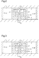
- a communication line 27 is formed in the movable member 3 to cause the corresponding one of the phase-advancing hydraulic chambers 7 of the variable valve timing mechanism 1 to communicate with the associated one of the phase-retarding hydraulic chambers 8 when the prohibiting operation of the lock mechanism 22 is performed.
- the communication line 27 is blocked by the pin 26 when the permitting operation of the lock mechanism 22 is complete.
- the movable member 3 is allowed to operate, that is, the pin 26 moves as illustrated in Fig. 3 , for example, to open a portion of the communication line 27. This causes the corresponding phase-advancing hydraulic chamber 7 of the variable valve timing mechanism 1 to communicate with the associated phase-retarding hydraulic chamber 8.
- oil is selectively supplied to and drained from the phase-advancing hydraulic chambers 7 and the phase-retarding hydraulic chambers 8 of the variable valve timing mechanism 1 via a plurality of oil lines forming a hydraulic circuit connecting the variable valve timing mechanism 1 to an oil pump 9. Also, oil is selectively supplied to and drained from the unlock chamber 22a of the lock mechanism 22 via a plurality of oil lines forming a hydraulic circuit connecting the lock mechanism 22 to the oil pump 9.
- An oil control valve 10 is arranged in the oil lines of these hydraulic circuits to change the oil supply-drainage modes of the oil lines for the variable valve timing mechanism 1 and the lock mechanism 22.
- variable valve timing mechanism 1 By changing the oil supply-drainage modes for the variable valve timing mechanism 1 and the lock mechanism 22 through the oil control valve 10, the movable member 3 of the variable valve timing mechanism 1 is operated. This changes the rotational phase of the camshaft 2 relative to the crankshaft and causes the lock mechanism 22 to perform the prohibiting operation or the permitting operation, as has been described.
- the oil control valve 10 is connected to the oil pump 9 via a supply line 11 and to an oil pan 12, which retains oil that has been drawn by the oil pump 9, via a drain line 13.
- the supply line 11 branches at a position downstream of the oil pump 9 and is thus connected to the oil control valve 10 at corresponding two positions.
- the oil control valve 10 is connected to each of the phase-advancing hydraulic chambers 7 of the variable valve timing mechanism 1 via a phase-advancing line 14 and to each of the phase-retarding hydraulic chambers 8 of the variable valve timing mechanism 1 via a phase-retarding line 15. Further, the oil control valve 10 is connected to the unlock chamber 22a of the lock mechanism 22, which is arranged in the variable valve timing mechanism 1, via an unlock oil line 23.
- the oil control valve 10 operates in any one of a plurality of operating modes.
- the operating modes of the oil control valve 10 include, for example, a lock mode, an oil filling mode, a phase-advancing mode, a maintaining mode, and a phase-retarding mode, which will be described below.
- the lock mode maintains a state in which the prohibiting operation by the lock mechanism 22 is complete, which is a state in which the pin 26 is inserted in the hole 25.
- the oil control valve 10 operates such that, in the state in which the prohibiting operation by the lock mechanism 22 is complete, the drain line 13 is connected to the unlock oil line 23 and the phase-advancing line 14 and the phase-retarding line 15 are each blocked from the supply line 11 and the drain line 13.
- the state in which the prohibiting operation by the lock mechanism 22 is complete which is, in other words, a state in which rotation of the movable member 3 relative to the case 4 in the variable valve timing mechanism 1 is prohibited, is maintained.
- the oil filling mode fills the variable valve timing mechanism 1 with oil to cause the variable valve timing mechanism 1 to start hydraulic operation in a state in which the variable valve timing mechanism 1 is without oil, or, for example, the engine is starting, and, at the same time, in the state in which the prohibiting operation by the lock mechanism 22 is complete (the state in which the pin 26 is inserted in the hole 25).
- the oil control valve 10 operates such that the supply line 11 is connected to the phase-advancing line 14, the unlock oil line 23 of the lock mechanism 22 is connected to the drain line 13, and the phase-retarding line 15 is blocked from the supply line 11 and the drain line 13.
- the phase-advancing mode advances the valve timing of the engine by advancing the rotational phase of the camshaft 2 ( Fig. 1 ) relative to the crankshaft.
- the oil control valve 10 operates such that the supply line 11 is connected to the phase-advancing line 14 and the unlock oil line 23 and the phase-retarding line 15 is connected to the drain line 13.
- This supplies oil to each phase-advancing hydraulic chamber 7 of the variable valve timing mechanism 1, and the unlock chamber 22a of the lock mechanism 22 and drains oil from each phase-retarding hydraulic chamber 8 of the variable valve timing mechanism 1.
- the lock mechanism 22 is switched to a permitting operation state and the movable member 3 of the variable valve timing mechanism 1 is rotated relative to the case 4 in the rightward direction as viewed in the drawing to advance the valve timing of the engine.
- the maintaining mode maintains the valve timing of the engine constant by maintaining the rotational phase of the camshaft 2 relative to the crankshaft constant.
- the oil control valve 10 operates such that the supply line 11 is connected to the unlock oil line 23 and the phase-advancing line 14 and the phase-retarding line 15 are both blocked from the supply line 11 and the drain line 13.
- This supplies oil to the unlock chamber 22a of the lock mechanism 22 and prohibits the oil supply/drainage to and from the phase-advancing hydraulic chambers 7 and the phase-retarding hydraulic chambers 8 of the variable valve timing mechanism 1.
- rotation of the movable member 3 relative to the case 4 in the variable valve timing mechanism 1 is stopped and the valve timing of the engine is maintained constant.
- the phase-retarding mode retards the valve timing of the engine by retarding the rotational phase of the camshaft 2 relative to the crankshaft.
- the oil control valve 10 operates such that the supply line 11 is connected to the phase-retarding line 15 and the unlock oil line 23, and the phase-advancing line 14 is connected to the drain line 13.
- This supplies oil to each phase-retarding hydraulic chamber 8 of the variable valve timing mechanism 1 and the unlock chamber 22a of the lock mechanism 22 and drains the oil from each phase-advancing hydraulic chamber 7 of the variable valve timing mechanism 1.
- the lock mechanism 22 is switched to the permitting operation state and the movable member 3 of the variable valve timing mechanism 1 is rotated relative to the case 4 in the leftward direction as viewed in the drawing. The valve timing of the engine is thus advanced.
- variable valve timing mechanism 1 are demanded to improve response by which the variable valve timing mechanism 1 is actuated and decrease oil leakage from the portions of the oil lines of the hydraulic circuits (the phase-advancing line 14, the phase-retarding line 15, and the unlock oil line 23) between the variable valve timing mechanism 1 and the oil control valve 10.
- the oil control valve 10 for example, may function as a bolt for fixing the movable member 3 of the variable valve timing mechanism 1 to the camshaft 2.
- the oil control valve 10 should be arranged in the camshaft 2.
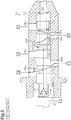
- Figs. 4 to 8 are cross-sectional views showing the oil control valve 10 in the above-described operating modes, which are the lock mode, the oil filling mode, the phase-advancing mode, the maintaining mode, and the phase-retarding mode.
- a spool valve 17 is arranged in a cylindrical housing 16.
- the spool valve 17 is movable along its axis.
- the urging force of a spring 20 provided in the housing 16 urges the spool valve 17 toward an end in the axial direction (to the left side as viewed in the drawings, hereinafter referred to as a reference end).
- An actuator 21, which presses the spool valve 17 against the urging force of the spring 20, and the spring 20 enable the spool valve 17 to move in the axial direction.
- the spool valve 17 is moved in the axial direction such that the pressing force and the urging force of the spring 20 equilibrate with each other. Through such movement of the spool valve 17, the position of the spool valve 17 in the axial direction is adjusted.
- a plurality of valve bodies 18a, 18b, 18c, 18d, and 18e are formed in the spool valve 17 sequentially in this order from an end portion of the spool valve 17 close to the actuator 21 and spaced apart at predetermined intervals.
- a plurality of holes 16a, 16b, 16c, 16d, and 16e are formed in the housing 16, into which the spool valve 17 is inserted, such that the holes 16a to 16e connect the corresponding oil lines of the hydraulic circuits (the supply line 11, the phase-advancing line 14, the phase-retarding line 15, and the unlock oil line 23) to the inner circumferential surface of the housing 16 and each extend linearly in a radial direction of the housing 16.
- a recess 16f is formed in the inner circumferential surface of the housing 16.
- the hole 16a is connected to the phase-advancing line 14, and the hole 16b is connected to the phase-retarding line 15.
- the hole 16c and the hole 16d are connected to the supply line 11, and the hole 16e is connected to the unlock oil line 23.
- the opening end of the housing 16 at the side close to the actuator 21 (the left side as viewed in the drawing) is connected to the drain line 13, out of the multiple oil lines of the hydraulic circuits, and communicates with a drainage passage 17a formed in the spool valve 17.
- An opening of the drainage passage 17a is formed at the end portion of the spool valve 17 at the side close to the actuator 21 (the left side as viewed in the drawing).
- the drainage passage 17a extends in the axial direction of the spool valve 17 with other openings of the drainage passage 17a formed in an axial middle portion of the spool valve 17, which is, more specifically, the outer circumferential surface of the portion of the spool valve 17 between the valve body 18c and the valve body 18d.
- the holes 16a, 16b, 16e and the recess 16f of the housing 16 each function as a port connected to the variable valve timing mechanism 1 and the lock mechanism 22. More specifically, the hole 16a functions as a port connected to the phase-advancing hydraulic chamber 7. The hole 16b and the recess 16f each function as a port connected to the phase-retarding hydraulic chamber 8. The hole 16e and the recess 16f each function as a port connected to the unlock chamber 22a.
- the ports are selectively opened and closed by the corresponding valve bodies 18a to 18e of the spool valve 17.
- This switches the operating mode of the oil control valve 10 to the corresponding one of the multiple operating modes, which are the lock mode, the oil filling mode, the phase-advancing mode, the maintaining mode, and the phase-retarding mode.
- the oil supply/drainage mode for the variable valve timing mechanism 1 ( Fig. 1 ) is changed.
- Such change of the oil supply/drainage mode for the variable valve timing mechanism 1 operates the movable member 3 of the variable valve timing mechanism 1 to change the rotational phase of the camshaft 2 relative to the crankshaft and operate the lock mechanism 22 of the variable valve timing mechanism 1.
- Fig. 9 is a graph representing changes in the open areas of the corresponding portions of the oil lines of the above-described hydraulic circuits in the oil control valve 10 at the time of movement of the spool valve 17 in the axial direction.
- the operating mode of the oil control valve 10 changes sequentially from the lock mode to the oil filling mode, the phase-advancing mode, the maintaining mode, and the phase-retarding mode.
- the solid line L1 represents changes in the open area of the oil line for draining oil from the unlock chamber 22a of the lock mechanism 22.
- the long dashed double-short dashed lines L2 represent changes in the open area of the oil line for supplying oil to each phase-advancing hydraulic chamber 7 of the variable valve timing mechanism 1.
- the broken lines L3 represent changes in the open area of the oil line for draining oil from each phase-retarding hydraulic chamber 8 of the variable valve timing mechanism 1.
- the solid lines L4 represent changes in the open area of the oil line for supplying oil to the unlock chamber 22a of the lock mechanism 22.
- the long dashed double-short dashed line L5 represents changes in the open area of the oil line for supplying oil to each phase-retarding hydraulic chamber 8 of the variable valve timing mechanism 1.
- the broken line L6 represents changes in the open area of the oil line for draining oil from each phase-advancing hydraulic chamber 7 of the variable valve timing mechanism 1. That is, the valve bodies 18a to 18e of the spool valve 17 and the holes 16a to 16e and the recess 16f of the housing 16 are formed such that the open areas of the above-described oil lines change in correspondence with movement of the spool valve 17 in the manners represented by the graph.
- the open area of the oil line for draining oil from the unlock chamber 22a of the lock mechanism 22 is greater than "0".
- the port connected to the unlock chamber 22a is held in an open state to cause the lock mechanism 22 to perform the prohibiting operation by the drainage of oil.
- the oil drained from the unlock chamber 22a passes through the oil control valve 10 in the manners represented in Figs. 4 and 5 .
- the open area of the oil line for draining oil from each phase-retarding hydraulic chamber 8 of the variable valve timing mechanism 1 is greater than 0.
- the oil in the phase-retarding hydraulic chamber 8 is drained via the drainage passage 17a, which is formed in the spool valve 17.
- the open area (represented by the long dashed double-short dashed lines L2) of the oil line for supplying the oil to each phase-advancing hydraulic chamber 7 of the variable valve timing mechanism 1 is greater than 0. In other words, in the second area, the oil is supplied to the phase-advancing hydraulic chamber 7.
- the oil drained from the phase-retarding hydraulic chamber 8 (the phase-retarding line 15) and the oil that should be supplied to the phase-advancing hydraulic chamber 7 (the phase-advancing line 14) pass through the oil control valve 10 in the manner represented in Fig. 6 .
- the aforementioned first and second areas are spaced from each other. More specifically, the second area is adjacent to the first area and located on the opposite side of the first area from the reference end (the left end of the axis of abscissas of Fig. 9 ) of the movement range with respect to the first area. That is, the first area is arranged between the reference end and the second area in the movement range. The first area and the second area are spaced apart at a predetermined distance.
- the operating mode of the oil control valve 10 is switched, for example, from the phase-retarding mode ( Fig. 8 ) to the phase-advancing mode ( Fig. 6 ).
- the position of the spool valve 17 may be adjusted to move the spool valve 17 toward the reference end such that the spool valve 17 is located in the second area. If the position of the spool valve 17 is adjusted in this manner, the oil drained from each phase-retarding hydraulic chamber 8 of the variable valve timing mechanism 1 is caused to flow in the drainage passage 17a, which is formed in the spool valve 17.
- Such flow of the oil in the drainage passage 17a applies force (hereinafter, fluid force) to the spool valve 17 in the axial direction of the spool valve 17.
- the fluid force is selectively increased and decreased through variation in the flow rate or flow amount of the oil flowing in the drainage passage 17a.
- Such increase/decrease of the fluid force and the urging force of the spring 20 acting on the spool valve 17 cause the spool valve 17 to resonate.
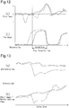
- the spool valve 17 vibrates greatly in the axial direction and thus moves in the manner represented in Fig. 1(a) , for example.
- the long dashed double-short dashed line in Fig. 11(a) represents the position (the target position) to which the spool valve 17 must be moved.
- the second area is adjacent to the first area and located on the opposite side of the first area from the reference end (the left end of the axis of abscissas of the graph) of the movement range of the spool valve 17. That is, the first area is arranged between the reference end and the second area in the movement range. Also, the first area and the second area are spaced apart at the predetermined distance. Therefore, even if the spool valve 17 vibrates and moves from a position in the second area toward the first area as has been described, the spool valve 17 does not enter the first area.
- section (a) represents changes in the intensity of the fluid force acting on the spool valve 17 in correspondence with movement of the spool valve 17.
- Section (b) represents changes in the flow amount of the oil drained via the drainage passage 17a in correspondence with the movement of the spool valve 17.
- the solid lines correspond to the oil control valve 10 of the illustrated embodiment, which has the characteristics of changes in the open areas represented in Fig. 9 with respect to the movement of the spool valve 17.
- the long dashed double-short dashed lines correspond to the oil control valve having the characteristics of changes in the open areas represented in Fig. 10 with respect to the movement of the spool valve.
- the flow amount of the oil drained via the drainage passage 17a increases in the second area, as represented by the solid line in Fig. 12(b) .
- the oil control valve having the characteristics of changes in the open areas represented in Fig. 10 has a second area enlarged toward the reference end (the left end of the axis of abscissas of the graph), compared to the oil control valve 10 of the illustrated embodiment.
- the area in which the flow amount of the oil drained via the drainage passage increases is also enlarged toward the reference end, compared to the second area represented by the solid line.
- section (a) represents movement of the spool valve 17 at the time of the aforementioned vibration of the spool valve 17 in the second area for values of the engine speed.
- Section (b) represents the rate of change of the rotational phase of the camshaft 2 relative to the crankshaft (the operating speed of the variable valve timing mechanism 1) at the time of the vibration for the respective values of the engine speed.
- the solid lines correspond to the oil control valve 10 of the illustrated embodiment, which has the characteristics of changes in the open areas represented in Fig. 9 with respect to the movement of the spool valve 17.
- the long dashed double-short dashed lines correspond to the oil control valve having the characteristics of changes in the open areas represented in Fig. 10 with respect to the movement of the spool valve.
- the oil control valve having the characteristics of changes in the open areas represented in Fig. 10 exhibits increased movement toward the reference end at the time of the aforementioned vibration of the spool valve, compared to the oil control valve 10 of the illustrated embodiment. Specifically, if, as represented by the long dashed double-short dashed line in Fig. 13(a) , the spool valve moves toward the reference end with respect to the long dashed short dashed line in the graph, the spool valve enters the first area and causes the lock mechanism 22 to perform unnecessary prohibiting operation. As represented by the long dashed double-short dashed line in Fig.
- the oil control valve 10 does not necessarily have to function as a bolt for fixing the movable member 3 of the variable valve timing mechanism 1 to the camshaft 2.
- An oil control valve 10 without such a function can be arranged at a position other than in the camshaft 2.
- the oil control valve 10 operating in the oil filling mode may supply oil to each phase-retarding hydraulic chamber 8 instead of each phase-advancing hydraulic chamber 7.
- the oil supplied to the phase-retarding hydraulic chamber 8 flows into the phase-advancing hydraulic chamber 7 via the communication line 27 of the lock mechanism 22. In this manner, the variable valve timing mechanism 1 is rapidly filled with the oil.
- the lock mechanism 22 does not necessarily have to include the communication line 27.
- the communication line 27 may thus be omitted.
- the lock mechanism 22 may fix the rotational position of the movable member 3 relative to the case 4 at a position other than the middle position in the relative rotation range of the movable member 3, which is, for example, a maximally retarded position or a maximally advanced position.
- the spring 20 may be omitted and the spool valve 17 may be fixed to the actuator 21, and the spool valve 17 may be moved solely by the actuator 21.
- the relationship between the positions of the first area and the second area with respect to the reference end of the movement range of the spool valve 17 may be reversed from that in the above illustrated embodiment.
- the drainage passage 17a is illustrated as an example of the passage formed in the spool valve 17.
- the passage formed in the spool valve 17 may be a passage through which oil is supplied to the variable valve timing mechanism 1 and the lock mechanism 22 or a passage through which oil is both supplied to and drained from the variable valve timing mechanism 1 and the lock mechanism 22.
- the second area is a movement area of the spool valve 17 that ensures such an operating mode of the oil control valve 10 that oil passes through the aforementioned passage.
- variable valve timing mechanism 1 may vary the valve timing of exhaust valves, or, in other words, the rotational phase of the exhaust camshaft relative to the crankshaft.
Landscapes
- Engineering & Computer Science (AREA)
- General Engineering & Computer Science (AREA)
- Mechanical Engineering (AREA)
- Valve Device For Special Equipments (AREA)
- Multiple-Way Valves (AREA)
- Sliding Valves (AREA)
Claims (3)
- Anordnung eines variablen Ventilmechanismus und eines Ölsteuerventils (10), wobei das Ölsteuerventil (10) Folgendes aufweist:ein Gehäuse (16) und ein Schieberventil (17), das in dem Gehäuse (16) angeordnet und in einer axialen Richtung des Schieberventils (17) beweglich ist, wobei das Ventil dadurch gekennzeichnet ist, dasseine Vielzahl von Anschlüssen, die mit dem variablen Ventilzeitmechanismus (1) und einem Sperrmechanismus (22) verbunden sind, in dem Gehäuse (16) ausgebildet sind,das Ölsteuerventil (10) angepasst ist, um Folgendes durchzuführen:Zufuhr/Abgabe von Öl zu und von dem variablen Ventilzeitmechanismus (1), um den variablen Ventilzeitmechanismus (1) durch ein Einstellen einer Position des Schieberventils (17) in der axialen Richtung hydraulisch zu betätigen, um wahlweise die Anschlüsse mit einem Ventilkörper (18c, 18d) des Schieberventils (17) zu öffnen und zu schließen; undZufuhr/Abgabe von Öl zu und von dem Sperrmechanismus (22), um eine verhindernde Betätigung eines Verhinderns einer Betätigung des variablen Ventilzeitmechanismus (1) und eine erlaubende Betätigung eines Erlaubens der Betätigung des variablen Ventilzeitmechanismus (1) auszuführen,wobei der variable Ventilzeitmechanismus (1) ein bewegliches Bauteil (3) hat, das ein Inneres eines Gehäuses (4) in eine Phasenvorversatzhydraulikkammer (7) und eine Phasenverzögerungshydraulikkammer (8) aufteilt,der variable Ventilzeitmechanismus (1) angepasst ist, um das bewegliche Bauteil (3) durch ein Zuführen von Öl zu einer von der Phasenvorversatz- und Phasenverzögerungshydraulikkammer (7, 8) und ein Abgeben von Öl von der anderen von der Phasenvorversatz- und Phasenverzögerungshydraulikkammer (7, 8) zu betätigen, wodurch eine Drehphase einer Nockenwelle (2) relativ zu einer Kurbelwelle geändert wird,ein Durchgang (17a), in den das Öl strömt, in dem Schieberventil (17) ausgebildet ist, undder Ventilkörper (18c, 18d) des Schieberventils (17) und die Anschlüsse des Gehäuses (16) derart ausgebildet sind, dass:ein Bewegungsbereich des Schieberventils (17) einen ersten Bereich (L1), in dem das Schieberventil (17) jene von den Anschlüssen öffnet, die mit dem Sperrmechanismus (22) verbunden sind, um die verhindernde Betätigung durch ein Abgeben von Öl von dem Sperrmechanismus (22) durchzuführen, und einen zweiten Bereich (L3) aufweist, in dem das Schieberventil (17) die Zufuhr/Abgabe von Öl zu und von dem variablen Ventilzeitmechanismus (1) durch den Durchgang (17a) durchführt;in dem zweiten Bereich (L3) das Öl zu der Phasenvorversatzhydraulikkammer (7) zugeführt wird und das Öl in der Phasenverzögerungshydraulikkammer (8) abgegeben wird;sich der erste Bereich (L1) an einer Position beabstandet von dem zweiten Bereich (L3) in dem Bewegungsbereich befindet, wobei der erste Bereich (L1) und der zweite Bereich (L3) mit einem vorbestimmten Abstand voneinander beabstandet sind; undin dem gesamten vorbestimmten Abstand das Öl zu der Phasenvorversatzhydraulikkammer (7) zugeführt wird und das Öl in der Phasenverzögerungshydraulikkammer (8) nicht abgegeben wird.
- Anordnung nach Anspruch 1, dadurch gekennzeichnet, dass
das Schieberventil (17) durch eine Feder (20) zu einem Referenzende des Bewegungsbereichs des Schieberventils (17) gedrängt wird,
der erste Bereich (L1) zwischen dem Referenzende und dem zweiten Bereich (L3) in dem Bewegungsbereich angeordnet ist, und
in dem zweiten Bereich (L3) das Öl, das von dem variablen Ventilzeitmechanismus (1) abgegeben wird, in den Durchgang (17a) strömt, der in dem Schieberventil (17) ausgebildet ist. - Anordnung nach Anspruch 2, dadurch gekennzeichnet, dass
der Sperrmechanismus (22) wahlweise einen Stift (26) einsetzt und zurückzieht, der in dem beweglichen Bauteil (3) angeordnet ist hinsichtlich eines Lochs (25), das in dem Gehäuse (4) ausgebildet ist, unter Verwendung einer Kraft, die durch einen Hydraulikdruck und eine Drängkraft der Feder (20) erzeugt wird,
der Sperrmechanismus (22) angepasst ist, um die verhindernde Betätigung durchzuführen, in der der Stift (26) in das Loch (25) unter Verwendung der Drängkraft durch ein Abgeben des Öls und ein dementsprechendes Verringern der Kraft, die durch den Hydraulikdruck erzeugt wird, eingesetzt wird,
der Sperrmechanismus (22) angepasst ist, um die erlaubende Betätigung durchzuführen, in der der Stift (26) aus dem Loch (25) entgegen der Drängkraft durch ein Aufnehmen der Zufuhr von Öl und ein dementsprechendes Erhöhen der Kraft, die durch den Hydraulikdruck erzeugt wird, zurückgezogen wird,
der Sperrmechanismus (22) eine Verbindungsleitung aufweist, die eine Verbindung zwischen der Phasenvorversatzhydraulikkammer (7) und der Phasenrückversatzhydraulikkammer (8) veranlasst, wenn der verhindernde Betrieb durchgeführt wird, und
in dem zweiten Bereich (L3) Öl zu der Phasenvorversatzhydraulikkammer (7) zugeführt wird und Öl von der Phasenrückversatzhydraulikkammer (8) des variablen Ventilzeitmechanismus (1) derart abgegeben wird, dass das Öl in den Durchgang strömt, der in dem Schieberventil (17) ausgebildet ist.
Applications Claiming Priority (2)
| Application Number | Priority Date | Filing Date | Title |
|---|---|---|---|
| JP2012233687A JP5772786B2 (ja) | 2012-10-23 | 2012-10-23 | オイルコントロールバルブ |
| PCT/JP2013/077638 WO2014065132A1 (ja) | 2012-10-23 | 2013-10-10 | オイルコントロールバルブ |
Publications (3)
| Publication Number | Publication Date |
|---|---|
| EP2913488A1 EP2913488A1 (de) | 2015-09-02 |
| EP2913488A4 EP2913488A4 (de) | 2016-01-20 |
| EP2913488B1 true EP2913488B1 (de) | 2018-06-06 |
Family
ID=50544512
Family Applications (1)
| Application Number | Title | Priority Date | Filing Date |
|---|---|---|---|
| EP13848528.9A Not-in-force EP2913488B1 (de) | 2012-10-23 | 2013-10-10 | Anordnung eines variablen ventilbetriebssystems und eines ölregelventils |
Country Status (5)
| Country | Link |
|---|---|
| US (1) | US9587523B2 (de) |
| EP (1) | EP2913488B1 (de) |
| JP (1) | JP5772786B2 (de) |
| CN (1) | CN104755710B (de) |
| WO (1) | WO2014065132A1 (de) |
Families Citing this family (4)
| Publication number | Priority date | Publication date | Assignee | Title |
|---|---|---|---|---|
| US10151222B2 (en) * | 2016-09-28 | 2018-12-11 | Schaeffler Technologies AG & Co. KG | Electric cam phasing system including an activatable lock |
| US11913559B2 (en) * | 2019-09-24 | 2024-02-27 | Eagle Industry Co., Ltd. | Spool valve |
| CN115087827B (zh) | 2020-02-19 | 2025-09-26 | 伊格尔工业股份有限公司 | 滑阀 |
| US12005044B1 (en) | 2022-11-29 | 2024-06-11 | Autism Therapeutics Inc. | Treatment of autism spectrum disorders with ergothioneine, selenoneine, or combinations thereof |
Family Cites Families (7)
| Publication number | Priority date | Publication date | Assignee | Title |
|---|---|---|---|---|
| JP3867897B2 (ja) * | 2001-12-05 | 2007-01-17 | アイシン精機株式会社 | 弁開閉時期制御装置 |
| JP4147490B2 (ja) | 2004-07-28 | 2008-09-10 | アイシン精機株式会社 | 弁開閉時期制御装置 |
| JP4888513B2 (ja) * | 2009-04-01 | 2012-02-29 | トヨタ自動車株式会社 | 内燃機関の可変動弁装置 |
| JP5126157B2 (ja) * | 2009-04-23 | 2013-01-23 | 株式会社デンソー | 内燃機関の可変バルブタイミング制御装置 |
| JP4752953B2 (ja) | 2009-06-10 | 2011-08-17 | 株式会社デンソー | バルブタイミング調整装置 |
| JP5375671B2 (ja) * | 2010-02-26 | 2013-12-25 | トヨタ自動車株式会社 | 流量制御弁及びこれを具備する内燃機関のバルブタイミング制御装置 |
| JP2012002099A (ja) * | 2010-06-15 | 2012-01-05 | Toyota Motor Corp | 内燃機関のバルブタイミング制御装置 |
-
2012
- 2012-10-23 JP JP2012233687A patent/JP5772786B2/ja active Active
-
2013
- 2013-10-10 EP EP13848528.9A patent/EP2913488B1/de not_active Not-in-force
- 2013-10-10 US US14/436,259 patent/US9587523B2/en not_active Expired - Fee Related
- 2013-10-10 CN CN201380054392.3A patent/CN104755710B/zh not_active Expired - Fee Related
- 2013-10-10 WO PCT/JP2013/077638 patent/WO2014065132A1/ja not_active Ceased
Non-Patent Citations (1)
| Title |
|---|
| None * |
Also Published As
| Publication number | Publication date |
|---|---|
| CN104755710B (zh) | 2017-06-09 |
| US20150285105A1 (en) | 2015-10-08 |
| CN104755710A (zh) | 2015-07-01 |
| JP2014084778A (ja) | 2014-05-12 |
| US9587523B2 (en) | 2017-03-07 |
| WO2014065132A1 (ja) | 2014-05-01 |
| EP2913488A4 (de) | 2016-01-20 |
| JP5772786B2 (ja) | 2015-09-02 |
| EP2913488A1 (de) | 2015-09-02 |
Similar Documents
| Publication | Publication Date | Title |
|---|---|---|
| US8662040B2 (en) | Oscillating-motor camshaft adjuster having a hydraulic valve | |
| JP6295317B2 (ja) | 2方向性油圧バイアス回路を有するカムトルク作動式可変カムシャフトタイミング装置 | |
| JP5582363B2 (ja) | 弁開閉時期制御装置 | |
| US6997150B2 (en) | CTA phaser with proportional oil pressure for actuation at engine condition with low cam torsionals | |
| EP2913488B1 (de) | Anordnung eines variablen ventilbetriebssystems und eines ölregelventils | |
| JP5471675B2 (ja) | オイル圧制御装置 | |
| JP2003172109A (ja) | 弁開閉時期制御装置 | |
| US20140261263A1 (en) | Dual lock pin phaser | |
| JP2013545013A (ja) | 中間位置ロックを備えたカムトルク駆動型位相器 | |
| JP2006177344A (ja) | 可変カムタイミングシステム | |
| US9341090B2 (en) | Oscillating-motor camshaft adjuster having a hydraulic valve | |
| JP6217240B2 (ja) | 制御弁及び制御弁の取付構造 | |
| JP2010209780A (ja) | 内燃機関の可変動弁機構 | |
| EP3321479B1 (de) | Vorrichtung zur steuerung der ventilöffnungs-/ventilschliesszeit | |
| CN109209548B (zh) | 具有两个锁定位置的可变凸轮轴正时装置 | |
| JP6255777B2 (ja) | 弁開閉時期制御装置 | |
| JP2017008791A (ja) | 弁開閉時期制御装置 | |
| JP6171731B2 (ja) | 制御弁 | |
| US9410454B2 (en) | Valve opening/closing timing control device | |
| US12098662B2 (en) | Camshaft adjuster | |
| JP5382428B2 (ja) | 弁開閉時期制御装置 | |
| JP5780415B2 (ja) | 油圧制御装置 | |
| KR102173098B1 (ko) | 고빈도 전환 가변 캠 타이밍 페이저 | |
| US9909464B2 (en) | Intermediate phase adjustment apparatus of CVVT | |
| JP2013142348A (ja) | バルブ特性制御装置 |
Legal Events
| Date | Code | Title | Description |
|---|---|---|---|
| PUAI | Public reference made under article 153(3) epc to a published international application that has entered the european phase |
Free format text: ORIGINAL CODE: 0009012 |
|
| 17P | Request for examination filed |
Effective date: 20150429 |
|
| AK | Designated contracting states |
Kind code of ref document: A1 Designated state(s): AL AT BE BG CH CY CZ DE DK EE ES FI FR GB GR HR HU IE IS IT LI LT LU LV MC MK MT NL NO PL PT RO RS SE SI SK SM TR |
|
| AX | Request for extension of the european patent |
Extension state: BA ME |
|
| RA4 | Supplementary search report drawn up and despatched (corrected) |
Effective date: 20151217 |
|
| RIC1 | Information provided on ipc code assigned before grant |
Ipc: F16K 3/24 20060101ALI20151211BHEP Ipc: F01L 1/356 20060101AFI20151211BHEP Ipc: F01L 1/344 20060101ALI20151211BHEP Ipc: F01L 1/34 20060101ALI20151211BHEP Ipc: F16K 11/07 20060101ALI20151211BHEP |
|
| DAX | Request for extension of the european patent (deleted) | ||
| 17Q | First examination report despatched |
Effective date: 20170227 |
|
| GRAP | Despatch of communication of intention to grant a patent |
Free format text: ORIGINAL CODE: EPIDOSNIGR1 |
|
| INTG | Intention to grant announced |
Effective date: 20171219 |
|
| GRAS | Grant fee paid |
Free format text: ORIGINAL CODE: EPIDOSNIGR3 |
|
| GRAA | (expected) grant |
Free format text: ORIGINAL CODE: 0009210 |
|
| AK | Designated contracting states |
Kind code of ref document: B1 Designated state(s): AL AT BE BG CH CY CZ DE DK EE ES FI FR GB GR HR HU IE IS IT LI LT LU LV MC MK MT NL NO PL PT RO RS SE SI SK SM TR |
|
| REG | Reference to a national code |
Ref country code: GB Ref legal event code: FG4D |
|
| REG | Reference to a national code |
Ref country code: CH Ref legal event code: EP Ref country code: AT Ref legal event code: REF Ref document number: 1006325 Country of ref document: AT Kind code of ref document: T Effective date: 20180615 |
|
| REG | Reference to a national code |
Ref country code: IE Ref legal event code: FG4D |
|
| REG | Reference to a national code |
Ref country code: DE Ref legal event code: R096 Ref document number: 602013038685 Country of ref document: DE |
|
| REG | Reference to a national code |
Ref country code: DE Ref legal event code: R084 Ref document number: 602013038685 Country of ref document: DE |
|
| REG | Reference to a national code |
Ref country code: NL Ref legal event code: MP Effective date: 20180606 |
|
| REG | Reference to a national code |
Ref country code: LT Ref legal event code: MG4D |
|
| PG25 | Lapsed in a contracting state [announced via postgrant information from national office to epo] |
Ref country code: SE Free format text: LAPSE BECAUSE OF FAILURE TO SUBMIT A TRANSLATION OF THE DESCRIPTION OR TO PAY THE FEE WITHIN THE PRESCRIBED TIME-LIMIT Effective date: 20180606 Ref country code: CY Free format text: LAPSE BECAUSE OF FAILURE TO SUBMIT A TRANSLATION OF THE DESCRIPTION OR TO PAY THE FEE WITHIN THE PRESCRIBED TIME-LIMIT Effective date: 20180606 Ref country code: BG Free format text: LAPSE BECAUSE OF FAILURE TO SUBMIT A TRANSLATION OF THE DESCRIPTION OR TO PAY THE FEE WITHIN THE PRESCRIBED TIME-LIMIT Effective date: 20180906 Ref country code: FI Free format text: LAPSE BECAUSE OF FAILURE TO SUBMIT A TRANSLATION OF THE DESCRIPTION OR TO PAY THE FEE WITHIN THE PRESCRIBED TIME-LIMIT Effective date: 20180606 Ref country code: NO Free format text: LAPSE BECAUSE OF FAILURE TO SUBMIT A TRANSLATION OF THE DESCRIPTION OR TO PAY THE FEE WITHIN THE PRESCRIBED TIME-LIMIT Effective date: 20180906 Ref country code: LT Free format text: LAPSE BECAUSE OF FAILURE TO SUBMIT A TRANSLATION OF THE DESCRIPTION OR TO PAY THE FEE WITHIN THE PRESCRIBED TIME-LIMIT Effective date: 20180606 Ref country code: ES Free format text: LAPSE BECAUSE OF FAILURE TO SUBMIT A TRANSLATION OF THE DESCRIPTION OR TO PAY THE FEE WITHIN THE PRESCRIBED TIME-LIMIT Effective date: 20180606 |
|
| PG25 | Lapsed in a contracting state [announced via postgrant information from national office to epo] |
Ref country code: GR Free format text: LAPSE BECAUSE OF FAILURE TO SUBMIT A TRANSLATION OF THE DESCRIPTION OR TO PAY THE FEE WITHIN THE PRESCRIBED TIME-LIMIT Effective date: 20180907 Ref country code: RS Free format text: LAPSE BECAUSE OF FAILURE TO SUBMIT A TRANSLATION OF THE DESCRIPTION OR TO PAY THE FEE WITHIN THE PRESCRIBED TIME-LIMIT Effective date: 20180606 Ref country code: HR Free format text: LAPSE BECAUSE OF FAILURE TO SUBMIT A TRANSLATION OF THE DESCRIPTION OR TO PAY THE FEE WITHIN THE PRESCRIBED TIME-LIMIT Effective date: 20180606 Ref country code: LV Free format text: LAPSE BECAUSE OF FAILURE TO SUBMIT A TRANSLATION OF THE DESCRIPTION OR TO PAY THE FEE WITHIN THE PRESCRIBED TIME-LIMIT Effective date: 20180606 |
|
| REG | Reference to a national code |
Ref country code: AT Ref legal event code: MK05 Ref document number: 1006325 Country of ref document: AT Kind code of ref document: T Effective date: 20180606 |
|
| PG25 | Lapsed in a contracting state [announced via postgrant information from national office to epo] |
Ref country code: NL Free format text: LAPSE BECAUSE OF FAILURE TO SUBMIT A TRANSLATION OF THE DESCRIPTION OR TO PAY THE FEE WITHIN THE PRESCRIBED TIME-LIMIT Effective date: 20180606 |
|
| PG25 | Lapsed in a contracting state [announced via postgrant information from national office to epo] |
Ref country code: AT Free format text: LAPSE BECAUSE OF FAILURE TO SUBMIT A TRANSLATION OF THE DESCRIPTION OR TO PAY THE FEE WITHIN THE PRESCRIBED TIME-LIMIT Effective date: 20180606 Ref country code: CZ Free format text: LAPSE BECAUSE OF FAILURE TO SUBMIT A TRANSLATION OF THE DESCRIPTION OR TO PAY THE FEE WITHIN THE PRESCRIBED TIME-LIMIT Effective date: 20180606 Ref country code: IS Free format text: LAPSE BECAUSE OF FAILURE TO SUBMIT A TRANSLATION OF THE DESCRIPTION OR TO PAY THE FEE WITHIN THE PRESCRIBED TIME-LIMIT Effective date: 20181006 Ref country code: RO Free format text: LAPSE BECAUSE OF FAILURE TO SUBMIT A TRANSLATION OF THE DESCRIPTION OR TO PAY THE FEE WITHIN THE PRESCRIBED TIME-LIMIT Effective date: 20180606 Ref country code: EE Free format text: LAPSE BECAUSE OF FAILURE TO SUBMIT A TRANSLATION OF THE DESCRIPTION OR TO PAY THE FEE WITHIN THE PRESCRIBED TIME-LIMIT Effective date: 20180606 Ref country code: PL Free format text: LAPSE BECAUSE OF FAILURE TO SUBMIT A TRANSLATION OF THE DESCRIPTION OR TO PAY THE FEE WITHIN THE PRESCRIBED TIME-LIMIT Effective date: 20180606 Ref country code: SK Free format text: LAPSE BECAUSE OF FAILURE TO SUBMIT A TRANSLATION OF THE DESCRIPTION OR TO PAY THE FEE WITHIN THE PRESCRIBED TIME-LIMIT Effective date: 20180606 |
|
| PGFP | Annual fee paid to national office [announced via postgrant information from national office to epo] |
Ref country code: DE Payment date: 20180925 Year of fee payment: 6 |
|
| PG25 | Lapsed in a contracting state [announced via postgrant information from national office to epo] |
Ref country code: IT Free format text: LAPSE BECAUSE OF FAILURE TO SUBMIT A TRANSLATION OF THE DESCRIPTION OR TO PAY THE FEE WITHIN THE PRESCRIBED TIME-LIMIT Effective date: 20180606 Ref country code: SM Free format text: LAPSE BECAUSE OF FAILURE TO SUBMIT A TRANSLATION OF THE DESCRIPTION OR TO PAY THE FEE WITHIN THE PRESCRIBED TIME-LIMIT Effective date: 20180606 |
|
| REG | Reference to a national code |
Ref country code: DE Ref legal event code: R097 Ref document number: 602013038685 Country of ref document: DE |
|
| PLBE | No opposition filed within time limit |
Free format text: ORIGINAL CODE: 0009261 |
|
| STAA | Information on the status of an ep patent application or granted ep patent |
Free format text: STATUS: NO OPPOSITION FILED WITHIN TIME LIMIT |
|
| 26N | No opposition filed |
Effective date: 20190307 |
|
| PG25 | Lapsed in a contracting state [announced via postgrant information from national office to epo] |
Ref country code: SI Free format text: LAPSE BECAUSE OF FAILURE TO SUBMIT A TRANSLATION OF THE DESCRIPTION OR TO PAY THE FEE WITHIN THE PRESCRIBED TIME-LIMIT Effective date: 20180606 Ref country code: DK Free format text: LAPSE BECAUSE OF FAILURE TO SUBMIT A TRANSLATION OF THE DESCRIPTION OR TO PAY THE FEE WITHIN THE PRESCRIBED TIME-LIMIT Effective date: 20180606 |
|
| REG | Reference to a national code |
Ref country code: CH Ref legal event code: PL |
|
| GBPC | Gb: european patent ceased through non-payment of renewal fee |
Effective date: 20181010 |
|
| REG | Reference to a national code |
Ref country code: BE Ref legal event code: MM Effective date: 20181031 |
|
| PG25 | Lapsed in a contracting state [announced via postgrant information from national office to epo] |
Ref country code: LU Free format text: LAPSE BECAUSE OF NON-PAYMENT OF DUE FEES Effective date: 20181010 Ref country code: MC Free format text: LAPSE BECAUSE OF FAILURE TO SUBMIT A TRANSLATION OF THE DESCRIPTION OR TO PAY THE FEE WITHIN THE PRESCRIBED TIME-LIMIT Effective date: 20180606 |
|
| REG | Reference to a national code |
Ref country code: IE Ref legal event code: MM4A |
|
| PG25 | Lapsed in a contracting state [announced via postgrant information from national office to epo] |
Ref country code: LI Free format text: LAPSE BECAUSE OF NON-PAYMENT OF DUE FEES Effective date: 20181031 Ref country code: FR Free format text: LAPSE BECAUSE OF NON-PAYMENT OF DUE FEES Effective date: 20181031 Ref country code: BE Free format text: LAPSE BECAUSE OF NON-PAYMENT OF DUE FEES Effective date: 20181031 Ref country code: CH Free format text: LAPSE BECAUSE OF NON-PAYMENT OF DUE FEES Effective date: 20181031 |
|
| PG25 | Lapsed in a contracting state [announced via postgrant information from national office to epo] |
Ref country code: IE Free format text: LAPSE BECAUSE OF NON-PAYMENT OF DUE FEES Effective date: 20181010 Ref country code: GB Free format text: LAPSE BECAUSE OF NON-PAYMENT OF DUE FEES Effective date: 20181010 |
|
| PG25 | Lapsed in a contracting state [announced via postgrant information from national office to epo] |
Ref country code: AL Free format text: LAPSE BECAUSE OF FAILURE TO SUBMIT A TRANSLATION OF THE DESCRIPTION OR TO PAY THE FEE WITHIN THE PRESCRIBED TIME-LIMIT Effective date: 20180606 |
|
| PG25 | Lapsed in a contracting state [announced via postgrant information from national office to epo] |
Ref country code: MT Free format text: LAPSE BECAUSE OF NON-PAYMENT OF DUE FEES Effective date: 20181010 |
|
| PG25 | Lapsed in a contracting state [announced via postgrant information from national office to epo] |
Ref country code: TR Free format text: LAPSE BECAUSE OF FAILURE TO SUBMIT A TRANSLATION OF THE DESCRIPTION OR TO PAY THE FEE WITHIN THE PRESCRIBED TIME-LIMIT Effective date: 20180606 |
|
| REG | Reference to a national code |
Ref country code: DE Ref legal event code: R119 Ref document number: 602013038685 Country of ref document: DE |
|
| PG25 | Lapsed in a contracting state [announced via postgrant information from national office to epo] |
Ref country code: PT Free format text: LAPSE BECAUSE OF FAILURE TO SUBMIT A TRANSLATION OF THE DESCRIPTION OR TO PAY THE FEE WITHIN THE PRESCRIBED TIME-LIMIT Effective date: 20180606 |
|
| PG25 | Lapsed in a contracting state [announced via postgrant information from national office to epo] |
Ref country code: HU Free format text: LAPSE BECAUSE OF FAILURE TO SUBMIT A TRANSLATION OF THE DESCRIPTION OR TO PAY THE FEE WITHIN THE PRESCRIBED TIME-LIMIT; INVALID AB INITIO Effective date: 20131010 Ref country code: MK Free format text: LAPSE BECAUSE OF NON-PAYMENT OF DUE FEES Effective date: 20180606 |
|
| PG25 | Lapsed in a contracting state [announced via postgrant information from national office to epo] |
Ref country code: DE Free format text: LAPSE BECAUSE OF NON-PAYMENT OF DUE FEES Effective date: 20200501 |