EP2912299B1 - Vorrichtung zum fördern von kraftstoff - Google Patents
Vorrichtung zum fördern von kraftstoff Download PDFInfo
- Publication number
- EP2912299B1 EP2912299B1 EP13762453.2A EP13762453A EP2912299B1 EP 2912299 B1 EP2912299 B1 EP 2912299B1 EP 13762453 A EP13762453 A EP 13762453A EP 2912299 B1 EP2912299 B1 EP 2912299B1
- Authority
- EP
- European Patent Office
- Prior art keywords
- latching
- filter housing
- filter
- coupling element
- case
- Prior art date
- Legal status (The legal status is an assumption and is not a legal conclusion. Google has not performed a legal analysis and makes no representation as to the accuracy of the status listed.)
- Active
Links
- 239000000446 fuel Substances 0.000 title claims description 33
- 230000008878 coupling Effects 0.000 claims description 47
- 238000010168 coupling process Methods 0.000 claims description 47
- 238000005859 coupling reaction Methods 0.000 claims description 47
- 239000002828 fuel tank Substances 0.000 description 9
- 238000005452 bending Methods 0.000 description 3
- 238000002485 combustion reaction Methods 0.000 description 3
- 238000010276 construction Methods 0.000 description 2
- 238000003780 insertion Methods 0.000 description 2
- 230000037431 insertion Effects 0.000 description 2
- 230000000295 complement effect Effects 0.000 description 1
- 230000001419 dependent effect Effects 0.000 description 1
- 238000009434 installation Methods 0.000 description 1
- 238000005086 pumping Methods 0.000 description 1
- 230000001105 regulatory effect Effects 0.000 description 1
Images


Classifications
-
- B—PERFORMING OPERATIONS; TRANSPORTING
- B01—PHYSICAL OR CHEMICAL PROCESSES OR APPARATUS IN GENERAL
- B01D—SEPARATION
- B01D35/00—Filtering devices having features not specifically covered by groups B01D24/00 - B01D33/00, or for applications not specifically covered by groups B01D24/00 - B01D33/00; Auxiliary devices for filtration; Filter housing constructions
- B01D35/02—Filters adapted for location in special places, e.g. pipe-lines, pumps, stop-cocks
- B01D35/027—Filters adapted for location in special places, e.g. pipe-lines, pumps, stop-cocks rigidly mounted in or on tanks or reservoirs
- B01D35/0276—Filtering elements with a vertical rotation or symmetry axis mounted on tanks or reservoirs
-
- B—PERFORMING OPERATIONS; TRANSPORTING
- B01—PHYSICAL OR CHEMICAL PROCESSES OR APPARATUS IN GENERAL
- B01D—SEPARATION
- B01D35/00—Filtering devices having features not specifically covered by groups B01D24/00 - B01D33/00, or for applications not specifically covered by groups B01D24/00 - B01D33/00; Auxiliary devices for filtration; Filter housing constructions
- B01D35/30—Filter housing constructions
-
- F—MECHANICAL ENGINEERING; LIGHTING; HEATING; WEAPONS; BLASTING
- F02—COMBUSTION ENGINES; HOT-GAS OR COMBUSTION-PRODUCT ENGINE PLANTS
- F02M—SUPPLYING COMBUSTION ENGINES IN GENERAL WITH COMBUSTIBLE MIXTURES OR CONSTITUENTS THEREOF
- F02M37/00—Apparatus or systems for feeding liquid fuel from storage containers to carburettors or fuel-injection apparatus; Arrangements for purifying liquid fuel specially adapted for, or arranged on, internal-combustion engines
- F02M37/0076—Details of the fuel feeding system related to the fuel tank
-
- F—MECHANICAL ENGINEERING; LIGHTING; HEATING; WEAPONS; BLASTING
- F02—COMBUSTION ENGINES; HOT-GAS OR COMBUSTION-PRODUCT ENGINE PLANTS
- F02M—SUPPLYING COMBUSTION ENGINES IN GENERAL WITH COMBUSTIBLE MIXTURES OR CONSTITUENTS THEREOF
- F02M37/00—Apparatus or systems for feeding liquid fuel from storage containers to carburettors or fuel-injection apparatus; Arrangements for purifying liquid fuel specially adapted for, or arranged on, internal-combustion engines
- F02M37/04—Feeding by means of driven pumps
- F02M37/08—Feeding by means of driven pumps electrically driven
- F02M37/10—Feeding by means of driven pumps electrically driven submerged in fuel, e.g. in reservoir
-
- F—MECHANICAL ENGINEERING; LIGHTING; HEATING; WEAPONS; BLASTING
- F02—COMBUSTION ENGINES; HOT-GAS OR COMBUSTION-PRODUCT ENGINE PLANTS
- F02M—SUPPLYING COMBUSTION ENGINES IN GENERAL WITH COMBUSTIBLE MIXTURES OR CONSTITUENTS THEREOF
- F02M37/00—Apparatus or systems for feeding liquid fuel from storage containers to carburettors or fuel-injection apparatus; Arrangements for purifying liquid fuel specially adapted for, or arranged on, internal-combustion engines
- F02M37/22—Arrangements for purifying liquid fuel specially adapted for, or arranged on, internal-combustion engines, e.g. arrangements in the feeding system
- F02M37/32—Arrangements for purifying liquid fuel specially adapted for, or arranged on, internal-combustion engines, e.g. arrangements in the feeding system characterised by filters or filter arrangements
- F02M37/50—Filters arranged in or on fuel tanks
-
- B—PERFORMING OPERATIONS; TRANSPORTING
- B01—PHYSICAL OR CHEMICAL PROCESSES OR APPARATUS IN GENERAL
- B01D—SEPARATION
- B01D2201/00—Details relating to filtering apparatus
- B01D2201/30—Filter housing constructions
- B01D2201/301—Details of removable closures, lids, caps, filter heads
- B01D2201/302—Details of removable closures, lids, caps, filter heads having inlet or outlet ports
-
- B—PERFORMING OPERATIONS; TRANSPORTING
- B01—PHYSICAL OR CHEMICAL PROCESSES OR APPARATUS IN GENERAL
- B01D—SEPARATION
- B01D2201/00—Details relating to filtering apparatus
- B01D2201/34—Seals or gaskets for filtering elements
- B01D2201/347—Radial sealings
Definitions
- the invention relates to a device for conveying fuel according to the preamble of the main claim.
- a device for pumping fuel out of the EP 2 094 965 B1 known, with a filter housing having at least two juxtaposed filter ports and is arranged interchangeably in a receptacle of a lid which is provided for closing an opening of a fuel tank.
- the filter ports are connected by the insertion of the filter housing into the receptacle of the lid in each case with a fuel line of the device.
- the filter housing is held with retaining means in the receptacle.
- the disadvantage is that the hydraulic connections between the filter connections and the fuel lines after installation of the filter housing in the receptacle of the lid are not accessible and thus can not be visually checked. As a result, errors in the assembly of the filter housing, in particular when replacing the filter housing in the garages, and resulting technical problems such as leaks, are not recognized or not timely.
- the device according to the invention with the characterizing features of the main claim has the advantage that the hydraulic connections between the filter connections and the fuel lines are accessible during assembly and thereby verifiable by a coupling element is provided, to which the fuel lines are hydraulically connected and the fuel lines releasably connects to the filter ports of the filter housing.
- a coupling element is provided, to which the fuel lines are hydraulically connected and the fuel lines releasably connects to the filter ports of the filter housing.
- the coupling element connects the fuel lines with the filter ports of the filter housing in a non-interchangeable manner. Connecting the fuel lines to the wrong filter connections is thereby prevented according to the Poka Yoke principle.
- the filter ports of the filter housing in each case protrude into a connection channel of the coupling element or vice versa, since in this way a simple seal between the filter port of the filter housing and the connection channel of the coupling element is possible, for example by means of O-rings.
- the filter connections and the corresponding connection channels are designed to be different from one another in such a way that the coupling element can only be mounted in one position. In this way it is prevented that when replacing the filter housing, the connections are incorrectly interconnected.
- the coupling element can be fastened to the filter housing with at least two latching or screw connections, since in this way higher forces than in the case of only one latching or screw connection can be accommodated.
- the filter housing has two latching elements spaced apart from one another and the coupling element has two further latching elements, one latching element of the filter housing forming a latching connection with a latching element of the coupling element and the filter connections being arranged between the latching elements.
- a latching element of the latching connection has a recess into which engages the other latching element of the latching connection with a projection.
- the latching element of the filter housing is formed in each case by a filter housing on the protruding web, each protruding through a detent opening of the coupling element, wherein the recess is provided on the projecting web of the filter housing and the projection in the detent opening of the coupling element.
- the latching connection in each case comprises a centering element which protrudes from the filter housing and projects together with the latching element of the filter housing in the latching opening of the coupling element, wherein in each case a latching element and a centering face each other and wherein the centering each at least partially positively against the Wall of the latching opening of the coupling element is applied.
- the coupling element is attached to the filter housing with little play.
- the two locking elements of the filter housing are arranged on the side facing away from the filter connections and the two centering on the filter terminals facing side or vice versa, since the locking connections can be easily opened in this way by an inwardly directed bending of the web-shaped locking elements.
- the protrusions in the latching openings are each arranged such that they bend the latching elements of the filter housing when joining the latching connection elastically to each other.
- an opening of the locking connections is made possible by an inwardly directed bending of the web-shaped locking elements.
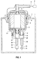
- Fig.1 shows a first sectional view of the device according to the invention.
- the device according to the invention serves to convey fuel from a fuel tank 1 to an internal combustion engine 2.
- the device has a filter housing 3, which has at least two adjacently arranged filter ports 4, 5 and is arranged interchangeably in a receptacle 6 of a cover 7.
- the lid 7 is provided, for example, to close an opening 8 in the fuel tank 1 tight.
- the filter connection 4 of the filter housing 3 is, for example, an input connection, through which the fuel passes into the filter housing 3.
- the filter connection 5 is, for example, an outlet connection, through which the fuel can flow back into the fuel tank 1.
- the filter housing 3 also has a further filter connection 9, which forms an outlet connection and allows the fuel to reach the internal combustion engine 1.
- the filter ports 4, 5 and the filter port 9 are arranged, for example, on opposite end faces of the filter housing 3, wherein the filter ports 4, 5 are arranged inside the fuel tank 1 and the filter port 9 outside the fuel tank 1.
- the Filter connections 4.5 arranged on a bottom 3.1 of the filter housing 3, which faces the interior of the fuel tank 1.
- the filter ports 4,5,9 are each connected to a fuel line 10,11,12, wherein the fuel line 10 of the filter port 4 is connected to a delivery unit 15 which sucks the fuel from the fuel tank 1 and the fuel line 10, the filter housing. 3 , the filter port 9 and the fuel line 11 to the internal combustion engine 1 promotes.
- the fuel line 11 is provided.
- the fuel line 12 of the filter connection 5 leads to a pressure regulating valve 16, which allows fuel to flow above a predetermined pressure in the filter housing 3 back into the fuel tank 1.
- a coupling element 19 is provided, to which the fuel lines 10, 12 are hydraulically connected in the correct way and which connects the fuel lines 10, 12 in a non-exchangeable manner to the filter connections 4, 5 of the filter housing 3 in a detachable manner. In this way it is prevented that the filter housing 3 is mounted in a replacement of the filter housing 3 in the wrong way.
- the filter connections 4, 5 of the filter housing 3 each project into a connection channel 20, 21 of the coupling element 19.
- the coupling element 19 has two coupling ports 22, 23 to which the fuel lines 10, 12 are connected.
- the filter connections 4, 5 and the corresponding connection channels 20, 21 are designed to be different from one another such that the coupling element 19 can only be mounted in one position.
- the filter ports 4, 5 have a different diameter and / or a different cantilevered height. Incorrect attachment of the coupling element 19 is thereby prevented.
- Fig.2 shows a second sectional view of the device according to the invention after Fig.1 ,
- the coupling element 19 is fastened to the filter housing 3 with two latching connections.
- the filter housing 3 has for this purpose two spaced-apart locking elements 25,26, for example, at the bottom 3.1 of the filter housing 3.
- two further locking elements 27,28 are provided, wherein each locking element 25,26 of the filter housing 3 with a latching element 27,28 the coupling element forms a latching connection.
- the filter ports 4.5 of the filter housing 3 lie between the locking elements 25-28.
- the filter housing 3 When replacing the filter housing 3, the filter housing 3 is removed from the receptacle 6 with the hydraulic system closed, ie with the connected coupling element 19 and the associated fuel lines 10,12.
- the fuel lines 10,12 are designed to be correspondingly long.
- the coupling element 19 is released by pressing the locking elements 25,26, the old filter housing 3 is removed and clipped a new filter housing 3 to the coupling element 19. An incorrect connection of the coupling element 19 is prevented by the inventive design.
- the new filter housing 3 is used with the connected coupling element and the fuel lines again in the receptacle 6 of the lid 7 and fixed.
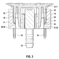
- Figure 3 shows a section of the device according to Fig.1 and Fig.2 with the coupling element according to the invention.
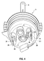
- Figure 4 shows a view from below of the filter housing according to the invention Fig.1 and Fig.2 ,
- the one latching element 25-28 a latching connection has a recess 31 into which the other latching element 25-28 of the latching connection engages with a projection 32, for example, engages positively.
- a projection 32 for example, engages positively.
- the shape of the projection 32 and the shape of the recess 31 are formed complementary to each other.
- the projection 32 has on the filter bottom 3.1 side facing a joining bevel 34 to facilitate the insertion of the web 25,26 in the latching opening 30.
- the latching elements 25,26 of the filter housing 3 are formed, for example, each by a filter housing 3 projecting web, each protruding through a latching opening 30 of the coupling element 19, wherein the recess 31 on the projecting web of the filter housing 3 and the projection 32 in the latching opening 30th the coupling element 19 is provided.
- the web 25,26 has a constriction 33 between the bottom 3.1 of the filter housing 3 and the recess 31 in order to place the bend of the web 25,26 in the region of the constriction ( Figure 4 ).
- the web 25,26 for example, roughened at its end facing away from the filter bottom 3.1, for example by a ripple or a knurl, so that slipping of the webs 25,26 is avoided.
- the latching connection comprises in each case, for example, also a centering element 35 which protrudes from the filter housing 3 and projects together with the latching element 25, 26 of the filter housing 3 into the latching opening 30 of the coupling element 19, wherein the latching element 25, 26 and the centering element 35 lie opposite one another ( Figure 3 and Figure 4 ).
- the centering element 35 is in each case at least partially positively against the wall of the latching opening 30 of the coupling element 19.
- the centering elements 35 are each arranged on the side facing the filter connections 4, 2, and the two latching elements 25, 26 of the filter housing 3 are arranged on the side facing away from the filter connections 4, 5 (FIG. Figure 4 )
- the protrusions 32 in the latching openings 30 are each arranged such that they bend the latching elements 25,26 of the filter housing 3 when joining the latching connection elastically to each other.
- Figure 5 shows a view from below of the filter housing according to the invention Fig.1 . Fig.2 and Figure 4 with the coupling element according to the invention.
Landscapes
- Engineering & Computer Science (AREA)
- Chemical & Material Sciences (AREA)
- Combustion & Propulsion (AREA)
- Mechanical Engineering (AREA)
- General Engineering & Computer Science (AREA)
- Chemical Kinetics & Catalysis (AREA)
- Filtration Of Liquid (AREA)
- Filtering Materials (AREA)
Applications Claiming Priority (2)
| Application Number | Priority Date | Filing Date | Title |
|---|---|---|---|
| DE102012219399.5A DE102012219399A1 (de) | 2012-10-24 | 2012-10-24 | Vorrichtung zum Fördern von Kraftstoff |
| PCT/EP2013/068782 WO2014063860A1 (de) | 2012-10-24 | 2013-09-11 | Vorrichtung zum fördern von kraftstoff |
Publications (2)
| Publication Number | Publication Date |
|---|---|
| EP2912299A1 EP2912299A1 (de) | 2015-09-02 |
| EP2912299B1 true EP2912299B1 (de) | 2016-11-30 |
Family
ID=49170682
Family Applications (1)
| Application Number | Title | Priority Date | Filing Date |
|---|---|---|---|
| EP13762453.2A Active EP2912299B1 (de) | 2012-10-24 | 2013-09-11 | Vorrichtung zum fördern von kraftstoff |
Country Status (7)
| Country | Link |
|---|---|
| EP (1) | EP2912299B1 (zh) |
| KR (1) | KR101979485B1 (zh) |
| CN (1) | CN104755741B (zh) |
| BR (1) | BR112015008091A2 (zh) |
| DE (1) | DE102012219399A1 (zh) |
| IN (1) | IN2015DN03193A (zh) |
| WO (1) | WO2014063860A1 (zh) |
Families Citing this family (2)
| Publication number | Priority date | Publication date | Assignee | Title |
|---|---|---|---|---|
| DE102015207137A1 (de) * | 2015-04-20 | 2016-10-20 | Robert Bosch Gmbh | Vorrichtung zum Fördern von Kraftstoff |
| WO2020146208A1 (en) * | 2019-01-11 | 2020-07-16 | Cummins Filtration Ip, Inc. | Multiple threaded connector for filter |
Family Cites Families (6)
| Publication number | Priority date | Publication date | Assignee | Title |
|---|---|---|---|---|
| DE10119554B4 (de) * | 2001-04-21 | 2005-12-08 | Siemens Ag | Kraftstoffbehälter |
| US7007678B2 (en) * | 2003-07-21 | 2006-03-07 | Visteon Global Technologies, Inc. | In-tank fuel filter |
| ITRE20040099A1 (it) * | 2004-08-03 | 2004-11-03 | Ufi Filters Spa | Filtro per carburante con dispositivo anticongelamento |
| CN2900839Y (zh) * | 2006-03-03 | 2007-05-16 | 十堰宏超工贸有限公司 | 一种可拆卸、重复使用的燃油滤清器 |
| DE102006054699A1 (de) * | 2006-11-21 | 2008-05-29 | Robert Bosch Gmbh | Tankflansch |
| KR101021516B1 (ko) * | 2009-10-26 | 2011-03-17 | 주식회사 코아비스 | 인탱크 필터의 탈착이 가능한 연료펌프모듈 |
-
2012
- 2012-10-24 DE DE102012219399.5A patent/DE102012219399A1/de not_active Withdrawn
-
2013
- 2013-09-11 WO PCT/EP2013/068782 patent/WO2014063860A1/de active Application Filing
- 2013-09-11 IN IN3193DEN2015 patent/IN2015DN03193A/en unknown
- 2013-09-11 CN CN201380054976.0A patent/CN104755741B/zh active Active
- 2013-09-11 EP EP13762453.2A patent/EP2912299B1/de active Active
- 2013-09-11 KR KR1020157012955A patent/KR101979485B1/ko active IP Right Grant
- 2013-09-11 BR BR112015008091A patent/BR112015008091A2/pt not_active Application Discontinuation
Non-Patent Citations (1)
| Title |
|---|
| None * |
Also Published As
| Publication number | Publication date |
|---|---|
| CN104755741A (zh) | 2015-07-01 |
| EP2912299A1 (de) | 2015-09-02 |
| WO2014063860A1 (de) | 2014-05-01 |
| KR20150074087A (ko) | 2015-07-01 |
| CN104755741B (zh) | 2017-10-03 |
| BR112015008091A2 (pt) | 2017-07-04 |
| KR101979485B1 (ko) | 2019-05-16 |
| IN2015DN03193A (zh) | 2015-10-02 |
| DE102012219399A1 (de) | 2014-04-24 |
Similar Documents
| Publication | Publication Date | Title |
|---|---|---|
| DE102004032572B4 (de) | Verbindungsanordnung mit Kontaktstift | |
| DE202008017031U1 (de) | Durchflussmengenregler | |
| DE102020115516A1 (de) | Wegeventil und Ventilkäfig für ein Wegeventil | |
| DE10115322A1 (de) | Kraftstoff-Einspritzvorrichtung für Brennkraftmaschinen, insbesondere Common-Rail-Injektor | |
| EP2912299B1 (de) | Vorrichtung zum fördern von kraftstoff | |
| WO2022073788A1 (de) | Verteilerbaugruppe, insbesondere für eine separationseinheit einer modularen prozess-vorrichtungsanordnung | |
| EP3601867A1 (de) | Anschlussvorrichtung für medienleitungen | |
| DE102007058238A1 (de) | Filteranordnung für einen Kraftstoffinjektor | |
| EP3803180A1 (de) | Anschlussvorrichtung für eine schlauchanordnung | |
| DE102010043438A1 (de) | Schutzkappe für einen flüssigkeitsführenden Verbindungsanschluss eines hydraulischen Systems | |
| DE102011088857A1 (de) | Schnellkupplung | |
| EP4264107A1 (de) | Steckverbinder mit verifizierungselement | |
| DE202012003702U1 (de) | Ventileinsatz für die Armatur eines Kompaktheizkörpers | |
| DE102019213522A1 (de) | Getriebeölmodul für eine Getriebeeinrichtung | |
| EP2855918A1 (de) | Vorrichtung zum zumessen von kraftstoff | |
| DE102004058624A1 (de) | Baukastensystem für Fluidpumpenvorrichtungen | |
| DE202009011004U1 (de) | Schnell de- und montierbarer Verbinder für ein Druckanzeigegerät | |
| EP2489799A1 (de) | Abwasserhebeanlage | |
| DE102013104597A1 (de) | Fluidstecker | |
| DE102008045154A1 (de) | Anordnung aus Kraftstoffrohr und Geberkopf sowie Verfahren zum Bereitstellen einer solchen | |
| DE102016015216A1 (de) | Elektromechanischer Aktor | |
| EP1953437B1 (de) | Verbindungsanordnung eines Systems an einer Endplatte | |
| EP2603738B1 (de) | Mischvorrichtung zur mischung von verbrennungsluft und gas sowie feuerungseinrichtung | |
| WO2015149774A1 (de) | Kupplungsgehäuseanordnung | |
| DE102018214597A1 (de) | Kraftstoff-Hochdruckpumpe |
Legal Events
| Date | Code | Title | Description |
|---|---|---|---|
| PUAI | Public reference made under article 153(3) epc to a published international application that has entered the european phase |
Free format text: ORIGINAL CODE: 0009012 |
|
| 17P | Request for examination filed |
Effective date: 20150526 |
|
| AK | Designated contracting states |
Kind code of ref document: A1 Designated state(s): AL AT BE BG CH CY CZ DE DK EE ES FI FR GB GR HR HU IE IS IT LI LT LU LV MC MK MT NL NO PL PT RO RS SE SI SK SM TR |
|
| AX | Request for extension of the european patent |
Extension state: BA ME |
|
| DAX | Request for extension of the european patent (deleted) | ||
| GRAP | Despatch of communication of intention to grant a patent |
Free format text: ORIGINAL CODE: EPIDOSNIGR1 |
|
| INTG | Intention to grant announced |
Effective date: 20160901 |
|
| GRAS | Grant fee paid |
Free format text: ORIGINAL CODE: EPIDOSNIGR3 |
|
| GRAA | (expected) grant |
Free format text: ORIGINAL CODE: 0009210 |
|
| AK | Designated contracting states |
Kind code of ref document: B1 Designated state(s): AL AT BE BG CH CY CZ DE DK EE ES FI FR GB GR HR HU IE IS IT LI LT LU LV MC MK MT NL NO PL PT RO RS SE SI SK SM TR |
|
| REG | Reference to a national code |
Ref country code: CH Ref legal event code: EP Ref country code: GB Ref legal event code: FG4D Free format text: NOT ENGLISH |
|
| REG | Reference to a national code |
Ref country code: AT Ref legal event code: REF Ref document number: 850038 Country of ref document: AT Kind code of ref document: T Effective date: 20161215 |
|
| REG | Reference to a national code |
Ref country code: IE Ref legal event code: FG4D Free format text: LANGUAGE OF EP DOCUMENT: GERMAN |
|
| REG | Reference to a national code |
Ref country code: DE Ref legal event code: R096 Ref document number: 502013005587 Country of ref document: DE |
|
| PG25 | Lapsed in a contracting state [announced via postgrant information from national office to epo] |
Ref country code: LV Free format text: LAPSE BECAUSE OF FAILURE TO SUBMIT A TRANSLATION OF THE DESCRIPTION OR TO PAY THE FEE WITHIN THE PRESCRIBED TIME-LIMIT Effective date: 20161130 |
|
| REG | Reference to a national code |
Ref country code: LT Ref legal event code: MG4D |
|
| REG | Reference to a national code |
Ref country code: NL Ref legal event code: MP Effective date: 20161130 |
|
| PG25 | Lapsed in a contracting state [announced via postgrant information from national office to epo] |
Ref country code: GR Free format text: LAPSE BECAUSE OF FAILURE TO SUBMIT A TRANSLATION OF THE DESCRIPTION OR TO PAY THE FEE WITHIN THE PRESCRIBED TIME-LIMIT Effective date: 20170301 Ref country code: SE Free format text: LAPSE BECAUSE OF FAILURE TO SUBMIT A TRANSLATION OF THE DESCRIPTION OR TO PAY THE FEE WITHIN THE PRESCRIBED TIME-LIMIT Effective date: 20161130 Ref country code: LT Free format text: LAPSE BECAUSE OF FAILURE TO SUBMIT A TRANSLATION OF THE DESCRIPTION OR TO PAY THE FEE WITHIN THE PRESCRIBED TIME-LIMIT Effective date: 20161130 Ref country code: NO Free format text: LAPSE BECAUSE OF FAILURE TO SUBMIT A TRANSLATION OF THE DESCRIPTION OR TO PAY THE FEE WITHIN THE PRESCRIBED TIME-LIMIT Effective date: 20170228 |
|
| PG25 | Lapsed in a contracting state [announced via postgrant information from national office to epo] |
Ref country code: RS Free format text: LAPSE BECAUSE OF FAILURE TO SUBMIT A TRANSLATION OF THE DESCRIPTION OR TO PAY THE FEE WITHIN THE PRESCRIBED TIME-LIMIT Effective date: 20161130 Ref country code: ES Free format text: LAPSE BECAUSE OF FAILURE TO SUBMIT A TRANSLATION OF THE DESCRIPTION OR TO PAY THE FEE WITHIN THE PRESCRIBED TIME-LIMIT Effective date: 20161130 Ref country code: HR Free format text: LAPSE BECAUSE OF FAILURE TO SUBMIT A TRANSLATION OF THE DESCRIPTION OR TO PAY THE FEE WITHIN THE PRESCRIBED TIME-LIMIT Effective date: 20161130 Ref country code: PT Free format text: LAPSE BECAUSE OF FAILURE TO SUBMIT A TRANSLATION OF THE DESCRIPTION OR TO PAY THE FEE WITHIN THE PRESCRIBED TIME-LIMIT Effective date: 20170330 Ref country code: FI Free format text: LAPSE BECAUSE OF FAILURE TO SUBMIT A TRANSLATION OF THE DESCRIPTION OR TO PAY THE FEE WITHIN THE PRESCRIBED TIME-LIMIT Effective date: 20161130 Ref country code: PL Free format text: LAPSE BECAUSE OF FAILURE TO SUBMIT A TRANSLATION OF THE DESCRIPTION OR TO PAY THE FEE WITHIN THE PRESCRIBED TIME-LIMIT Effective date: 20161130 |
|
| PG25 | Lapsed in a contracting state [announced via postgrant information from national office to epo] |
Ref country code: NL Free format text: LAPSE BECAUSE OF FAILURE TO SUBMIT A TRANSLATION OF THE DESCRIPTION OR TO PAY THE FEE WITHIN THE PRESCRIBED TIME-LIMIT Effective date: 20161130 |
|
| PG25 | Lapsed in a contracting state [announced via postgrant information from national office to epo] |
Ref country code: SK Free format text: LAPSE BECAUSE OF FAILURE TO SUBMIT A TRANSLATION OF THE DESCRIPTION OR TO PAY THE FEE WITHIN THE PRESCRIBED TIME-LIMIT Effective date: 20161130 Ref country code: EE Free format text: LAPSE BECAUSE OF FAILURE TO SUBMIT A TRANSLATION OF THE DESCRIPTION OR TO PAY THE FEE WITHIN THE PRESCRIBED TIME-LIMIT Effective date: 20161130 Ref country code: DK Free format text: LAPSE BECAUSE OF FAILURE TO SUBMIT A TRANSLATION OF THE DESCRIPTION OR TO PAY THE FEE WITHIN THE PRESCRIBED TIME-LIMIT Effective date: 20161130 Ref country code: CZ Free format text: LAPSE BECAUSE OF FAILURE TO SUBMIT A TRANSLATION OF THE DESCRIPTION OR TO PAY THE FEE WITHIN THE PRESCRIBED TIME-LIMIT Effective date: 20161130 Ref country code: RO Free format text: LAPSE BECAUSE OF FAILURE TO SUBMIT A TRANSLATION OF THE DESCRIPTION OR TO PAY THE FEE WITHIN THE PRESCRIBED TIME-LIMIT Effective date: 20161130 |
|
| PG25 | Lapsed in a contracting state [announced via postgrant information from national office to epo] |
Ref country code: SM Free format text: LAPSE BECAUSE OF FAILURE TO SUBMIT A TRANSLATION OF THE DESCRIPTION OR TO PAY THE FEE WITHIN THE PRESCRIBED TIME-LIMIT Effective date: 20161130 Ref country code: BG Free format text: LAPSE BECAUSE OF FAILURE TO SUBMIT A TRANSLATION OF THE DESCRIPTION OR TO PAY THE FEE WITHIN THE PRESCRIBED TIME-LIMIT Effective date: 20170228 |
|
| REG | Reference to a national code |
Ref country code: DE Ref legal event code: R097 Ref document number: 502013005587 Country of ref document: DE |
|
| REG | Reference to a national code |
Ref country code: FR Ref legal event code: PLFP Year of fee payment: 5 |
|
| PLBE | No opposition filed within time limit |
Free format text: ORIGINAL CODE: 0009261 |
|
| STAA | Information on the status of an ep patent application or granted ep patent |
Free format text: STATUS: NO OPPOSITION FILED WITHIN TIME LIMIT |
|
| 26N | No opposition filed |
Effective date: 20170831 |
|
| PG25 | Lapsed in a contracting state [announced via postgrant information from national office to epo] |
Ref country code: SI Free format text: LAPSE BECAUSE OF FAILURE TO SUBMIT A TRANSLATION OF THE DESCRIPTION OR TO PAY THE FEE WITHIN THE PRESCRIBED TIME-LIMIT Effective date: 20161130 |
|
| REG | Reference to a national code |
Ref country code: CH Ref legal event code: PL |
|
| GBPC | Gb: european patent ceased through non-payment of renewal fee |
Effective date: 20170911 |
|
| PG25 | Lapsed in a contracting state [announced via postgrant information from national office to epo] |
Ref country code: MC Free format text: LAPSE BECAUSE OF FAILURE TO SUBMIT A TRANSLATION OF THE DESCRIPTION OR TO PAY THE FEE WITHIN THE PRESCRIBED TIME-LIMIT Effective date: 20161130 |
|
| REG | Reference to a national code |
Ref country code: IE Ref legal event code: MM4A |
|
| REG | Reference to a national code |
Ref country code: BE Ref legal event code: MM Effective date: 20170930 |
|
| PG25 | Lapsed in a contracting state [announced via postgrant information from national office to epo] |
Ref country code: LU Free format text: LAPSE BECAUSE OF NON-PAYMENT OF DUE FEES Effective date: 20170911 |
|
| PG25 | Lapsed in a contracting state [announced via postgrant information from national office to epo] |
Ref country code: GB Free format text: LAPSE BECAUSE OF NON-PAYMENT OF DUE FEES Effective date: 20170911 Ref country code: LI Free format text: LAPSE BECAUSE OF NON-PAYMENT OF DUE FEES Effective date: 20170930 Ref country code: CH Free format text: LAPSE BECAUSE OF NON-PAYMENT OF DUE FEES Effective date: 20170930 Ref country code: IE Free format text: LAPSE BECAUSE OF NON-PAYMENT OF DUE FEES Effective date: 20170911 |
|
| PG25 | Lapsed in a contracting state [announced via postgrant information from national office to epo] |
Ref country code: BE Free format text: LAPSE BECAUSE OF NON-PAYMENT OF DUE FEES Effective date: 20170930 |
|
| REG | Reference to a national code |
Ref country code: FR Ref legal event code: PLFP Year of fee payment: 6 |
|
| PG25 | Lapsed in a contracting state [announced via postgrant information from national office to epo] |
Ref country code: MT Free format text: LAPSE BECAUSE OF FAILURE TO SUBMIT A TRANSLATION OF THE DESCRIPTION OR TO PAY THE FEE WITHIN THE PRESCRIBED TIME-LIMIT Effective date: 20161130 |
|
| PGFP | Annual fee paid to national office [announced via postgrant information from national office to epo] |
Ref country code: IT Payment date: 20180921 Year of fee payment: 6 Ref country code: FR Payment date: 20180921 Year of fee payment: 6 |
|
| PG25 | Lapsed in a contracting state [announced via postgrant information from national office to epo] |
Ref country code: HU Free format text: LAPSE BECAUSE OF FAILURE TO SUBMIT A TRANSLATION OF THE DESCRIPTION OR TO PAY THE FEE WITHIN THE PRESCRIBED TIME-LIMIT; INVALID AB INITIO Effective date: 20130911 |
|
| PG25 | Lapsed in a contracting state [announced via postgrant information from national office to epo] |
Ref country code: CY Free format text: LAPSE BECAUSE OF FAILURE TO SUBMIT A TRANSLATION OF THE DESCRIPTION OR TO PAY THE FEE WITHIN THE PRESCRIBED TIME-LIMIT Effective date: 20161130 |
|
| REG | Reference to a national code |
Ref country code: AT Ref legal event code: MM01 Ref document number: 850038 Country of ref document: AT Kind code of ref document: T Effective date: 20180911 |
|
| PG25 | Lapsed in a contracting state [announced via postgrant information from national office to epo] |
Ref country code: MK Free format text: LAPSE BECAUSE OF FAILURE TO SUBMIT A TRANSLATION OF THE DESCRIPTION OR TO PAY THE FEE WITHIN THE PRESCRIBED TIME-LIMIT Effective date: 20161130 |
|
| PG25 | Lapsed in a contracting state [announced via postgrant information from national office to epo] |
Ref country code: AT Free format text: LAPSE BECAUSE OF NON-PAYMENT OF DUE FEES Effective date: 20180911 |
|
| PG25 | Lapsed in a contracting state [announced via postgrant information from national office to epo] |
Ref country code: TR Free format text: LAPSE BECAUSE OF FAILURE TO SUBMIT A TRANSLATION OF THE DESCRIPTION OR TO PAY THE FEE WITHIN THE PRESCRIBED TIME-LIMIT Effective date: 20161130 |
|
| PG25 | Lapsed in a contracting state [announced via postgrant information from national office to epo] |
Ref country code: AL Free format text: LAPSE BECAUSE OF FAILURE TO SUBMIT A TRANSLATION OF THE DESCRIPTION OR TO PAY THE FEE WITHIN THE PRESCRIBED TIME-LIMIT Effective date: 20161130 Ref country code: IS Free format text: LAPSE BECAUSE OF FAILURE TO SUBMIT A TRANSLATION OF THE DESCRIPTION OR TO PAY THE FEE WITHIN THE PRESCRIBED TIME-LIMIT Effective date: 20170330 |
|
| PG25 | Lapsed in a contracting state [announced via postgrant information from national office to epo] |
Ref country code: IT Free format text: LAPSE BECAUSE OF NON-PAYMENT OF DUE FEES Effective date: 20190911 |
|
| PG25 | Lapsed in a contracting state [announced via postgrant information from national office to epo] |
Ref country code: FR Free format text: LAPSE BECAUSE OF NON-PAYMENT OF DUE FEES Effective date: 20190930 |
|
| PGFP | Annual fee paid to national office [announced via postgrant information from national office to epo] |
Ref country code: DE Payment date: 20231124 Year of fee payment: 11 |