EP2907698A1 - Dispositif de commande de feu stop - Google Patents
Dispositif de commande de feu stop Download PDFInfo
- Publication number
- EP2907698A1 EP2907698A1 EP13844855.0A EP13844855A EP2907698A1 EP 2907698 A1 EP2907698 A1 EP 2907698A1 EP 13844855 A EP13844855 A EP 13844855A EP 2907698 A1 EP2907698 A1 EP 2907698A1
- Authority
- EP
- European Patent Office
- Prior art keywords
- regenerative torque
- vehicle
- torque value
- lamp control
- status information
- Prior art date
- Legal status (The legal status is an assumption and is not a legal conclusion. Google has not performed a legal analysis and makes no representation as to the accuracy of the status listed.)
- Withdrawn
Links
Images


Classifications
-
- B—PERFORMING OPERATIONS; TRANSPORTING
- B60—VEHICLES IN GENERAL
- B60L—PROPULSION OF ELECTRICALLY-PROPELLED VEHICLES; SUPPLYING ELECTRIC POWER FOR AUXILIARY EQUIPMENT OF ELECTRICALLY-PROPELLED VEHICLES; ELECTRODYNAMIC BRAKE SYSTEMS FOR VEHICLES IN GENERAL; MAGNETIC SUSPENSION OR LEVITATION FOR VEHICLES; MONITORING OPERATING VARIABLES OF ELECTRICALLY-PROPELLED VEHICLES; ELECTRIC SAFETY DEVICES FOR ELECTRICALLY-PROPELLED VEHICLES
- B60L7/00—Electrodynamic brake systems for vehicles in general
- B60L7/10—Dynamic electric regenerative braking
-
- B—PERFORMING OPERATIONS; TRANSPORTING
- B60—VEHICLES IN GENERAL
- B60L—PROPULSION OF ELECTRICALLY-PROPELLED VEHICLES; SUPPLYING ELECTRIC POWER FOR AUXILIARY EQUIPMENT OF ELECTRICALLY-PROPELLED VEHICLES; ELECTRODYNAMIC BRAKE SYSTEMS FOR VEHICLES IN GENERAL; MAGNETIC SUSPENSION OR LEVITATION FOR VEHICLES; MONITORING OPERATING VARIABLES OF ELECTRICALLY-PROPELLED VEHICLES; ELECTRIC SAFETY DEVICES FOR ELECTRICALLY-PROPELLED VEHICLES
- B60L3/00—Electric devices on electrically-propelled vehicles for safety purposes; Monitoring operating variables, e.g. speed, deceleration or energy consumption
-
- B—PERFORMING OPERATIONS; TRANSPORTING
- B60—VEHICLES IN GENERAL
- B60Q—ARRANGEMENT OF SIGNALLING OR LIGHTING DEVICES, THE MOUNTING OR SUPPORTING THEREOF OR CIRCUITS THEREFOR, FOR VEHICLES IN GENERAL
- B60Q1/00—Arrangement of optical signalling or lighting devices, the mounting or supporting thereof or circuits therefor
- B60Q1/26—Arrangement of optical signalling or lighting devices, the mounting or supporting thereof or circuits therefor the devices being primarily intended to indicate the vehicle, or parts thereof, or to give signals, to other traffic
- B60Q1/44—Arrangement of optical signalling or lighting devices, the mounting or supporting thereof or circuits therefor the devices being primarily intended to indicate the vehicle, or parts thereof, or to give signals, to other traffic for indicating braking action or preparation for braking, e.g. by detection of the foot approaching the brake pedal
- B60Q1/444—Arrangement of optical signalling or lighting devices, the mounting or supporting thereof or circuits therefor the devices being primarily intended to indicate the vehicle, or parts thereof, or to give signals, to other traffic for indicating braking action or preparation for braking, e.g. by detection of the foot approaching the brake pedal with indication of the braking strength or speed changes, e.g. by changing shape or intensity of the indication
-
- B—PERFORMING OPERATIONS; TRANSPORTING
- B60—VEHICLES IN GENERAL
- B60L—PROPULSION OF ELECTRICALLY-PROPELLED VEHICLES; SUPPLYING ELECTRIC POWER FOR AUXILIARY EQUIPMENT OF ELECTRICALLY-PROPELLED VEHICLES; ELECTRODYNAMIC BRAKE SYSTEMS FOR VEHICLES IN GENERAL; MAGNETIC SUSPENSION OR LEVITATION FOR VEHICLES; MONITORING OPERATING VARIABLES OF ELECTRICALLY-PROPELLED VEHICLES; ELECTRIC SAFETY DEVICES FOR ELECTRICALLY-PROPELLED VEHICLES
- B60L2250/00—Driver interactions
- B60L2250/10—Driver interactions by alarm
Definitions
- the present invention relates to a brake lamp control device for controlling brake lamps which serve to notify nearby persons of deceleration of a vehicle.
- Patent document 1 a reference deceleration rate is set so as to vary depending on the vehicle speed and the brake lamps are turned on upon occurrence of a vehicle deceleration rate that exceeds the reference deceleration rate.
- Patent document 1 JP-A-4-358935
- Patent document 1 has a problem that since an actual vehicle speed (deceleration rate) is compared with a reference deceleration rate, the brake lamps can be turned on only after occurrence of a deceleration rate that is higher than a prescribed rate irrespective of a running road surface situation (e.g., a downhill road).
- a vehicle to be controlled is an electric vehicle which can be accelerated and decelerated by controlling the output torque of a motor
- strong deceleration-side torque can be used more easily than in gasoline vehicles. Therefore, when it is expected that an intense deceleration operation will be caused by an event other than a manipulation of the brake pedal, it is desirable to notify nearby persons of the deceleration as early as possible.
- the brake lamps are controlled on the basis of a deceleration rate as in the above-described Patent document 1, the brake lamps are turned on after actual decrease of the vehicle speed, which results in a problem that the drivers of nearby vehicles would feel uncomfortable.
- nearby vehicles can be notified of deceleration by a sound that is associated with engine braking.
- a problem arises that the drivers of nearby vehicles unlikely realize the deceleration.
- the present invention has been made in view of the above-described problems in the prior art, and an object of the present invention is therefore to notify nearby persons properly of a deceleration operation that is caused by an event other than a manipulation of a brake pedal.
- the present invention provides a brake lamp control device for controlling turn-on/off of a brake lamp of a vehicle in which braking power is obtained by increase of regenerative torque produced by a motor, characterized by comprising: running status information acquiring means which acquires running status information of the vehicle; manipulation status information acquiring means which acquires manipulation status information of the vehicle; regenerative torque calculating means which calculates a regenerative torque value of the motor based on the running status information and the manipulation status information; and regeneration lamp control means which turns on the brake lamp if the regenerative torque value calculated by the regenerative torque calculating means is on the regeneration side of and larger than the a predetermined reference regenerative torque value.
- a turn-on control is performed on the brake lamp if a regenerative torque value for the motor is on the regeneration side of and larger than the predetermined reference regenerative torque value.
- the running status information acquiring means may comprise a vehicle speed sensor which detects a vehicle speed of the vehicle, and the reference regenerative torque value may be varied based on the vehicle speed.
- the regenerative torque value can be varied based on the vehicle speed, it can be changed properly in accordance with the running status of the vehicle.
- the manipulation status information acquiring means may comprise a pedal sensor which detects a status of an accelerator pedal or a brake pedal of the vehicle, and the regenerative torque calculating means may calculate the regenerative torque from the vehicle speed and the status of the accelerator pedal or the brake pedal.
- a regenerative torque value is calculated from a vehicle speed and a status of the accelerator pedal or the brake pedal, a regenerative torque value can be calculated correctly on the basis of a vehicle running status and manipulation status.
- the vehicle may further comprise downhill road judging means which judges whether or not a road on which the vehicle runs is a downhill road. If it is judged that the road on which the vehicle runs is the downhill road, the regeneration lamp control means may turn off the brake lamp even if the calculated regenerative torque value is on the regeneration side of and larger than the reference regenerative torque value.
- the brake lamp in the case where the road on which the vehicle is running is a downhill road, the brake lamp is turned off or kept off even if a calculated regenerative torque value is larger than the reference regenerative torque value. This makes it possible to turn off the brake lamp in the case where the necessity of announcement using the brake lamp is low as exemplified by a case of running on a long downhill road in which a deceleration state continues or deceleration does not occur though regenerative torque is being produced.
- the reference regenerative torque value may be a preset regenerative torque value that is obtained by cancellation of an accelerator manipulation on the vehicle.
- the reference regenerative torque value is set approximately equal to a regenerative torque value corresponding to what is called engine braking.
- the brake lamp can be turned on in the case where deceleration that is higher than would occur during engine braking may occur and hence it is necessary to notify nearby vehicles etc. of the deceleration.
- the vehicle is of such a type that selection can be made between multiple regeneration modes.
- the regenerative torque calculating means may calculate the regenerative torque value of the motor based on a vehicle speed of the vehicle and a selected regeneration mode.
- the invention makes it possible to notify nearby persons properly of a deceleration operation that is caused by an event other than a manipulation of a brake pedal.
- Fig. 1 is a block diagram showing the configuration of a brake lamp control device 10 according to the embodiment.
- the brake lamp control device 10 according to the embodiment is a device for controlling the turning-on/off of brake lamps 202 of a vehicle in which strong braking power is obtained by increase of regenerative torque that is produced by amotor.
- the embodiment is directed to an electric vehicle that runs on drive torque produced by a motor (an example vehicle incorporating the brake lamp control device 10).
- the brake lamp control device 10 is implemented in such a manner that an ECU (not shown) runs a control program using a CPU, the ECU being configured so as to include, for example, the CPU, a ROM which is stored with the control program etc., a RAM which serves as a working area of the control program, an EEPROM which holds various kinds of data in a rewritable manner, an interface unit for interfacing with peripheral circuits etc., and other units.
- the brake lamp control device 10 is composed of a running status information acquiring means 102, a manipulation status information acquiring means 104, a control torque calculating means 106 (which corresponds to the term "regenerative torque calculatingmeans" used in the claims), a regeneration lamp control means 108, and a downhill road judging means 110.
- the running status information acquiring means 102 acquires running status information of the vehicle. Examples of running status information are vehicle speed information and acceleration information.
- the running status information acquiring means 102 acquires speed information and acceleration information from, for example, a vehicle speed sensor 204 and an acceleration sensor 206 which are provided in the vehicle.
- the running status information acquiring means 102 acquires crank shaft rotation speed information and propeller shaft rotation speed information from shaft rotation sensors 205.
- the running status information acquiring means 102 may also acquire, as running status information, vehicle current position information, current position inclination information, or the like.
- the manipulation status information acquiring means 104 acquires manipulation status information of the vehicle.
- manipulation status information are such kinds of information as step-on amounts of the accelerator pedal and the brake pedal of the vehicle, a setting status of a running mode such as an economical mode or a sport mode, a setting status of a cruise control function, and a setting status of an ASL (auto speed limiter) function.
- the manipulation status information acquiring means 104 acquires above kinds of information from such things provided in the vehicle as the accelerator pedal (more specifically, an accelerator pedal sensor) 208, the brake pedal (more specifically, a brake pedal sensor) 210, a mode switch 212 for switching between the runningmodes, a CC switch 214 for setting the cruise control function, and an ASL switch 216 for setting the ASL function.
- the control torque calculating means 106 calculates a regenerative torque value for the motor on the basis of the running status information acquired by the running status information acquiring means 102 and the manipulation status information acquired by the manipulation status information acquiring means 104.
- the control torque calculating means 106 acquires a request torque value that is requested by a drive manipulation (stepping on the accelerator pedal or the brake pedal) of the driver, the cruise control function (more specifically, a cruise control system that realizes the cruise control function), the ASL function (more specifically, an ASL system that realizes the ASL function), etc.
- the control torque calculating means 106 calculates a control torque value (regenerative torque value) to be used for an actual drive power control on the motor on the basis of the request torque value.
- the request torque value changes instantaneously from 0 to -100.
- the control torque calculating means 106 changes the control torque value stepwise from 0 to -100 in accordance with the power producing ability of the motor, which allows the motor to operate smoothly.
- the request torque value changes instantaneously from 0 to 100.
- the control torque calculating means 106 changes the control torque value stepwise from 0 to 100 in accordance with the power producing ability of the motor.
- the regeneration lamp control means 108 turns on the brake lamps 202 if the regenerative torque value calculated by the control torque calculatingmeans 106 is larger than a predetermined reference regenerative torque value.
- the reference regenerative torque value is set equal to a regenerative torque value that would be obtained during engine braking.
- regenerative torque corresponding to engine braking There are two kinds of regenerative torque: regenerative torque corresponding to engine braking and regenerative torque that is produced according to a brake manipulation amount.
- Regenerative torque corresponding to engine braking is produced in the following manner.
- the information to that effect is sent to the control torque calculating means 106 via the manipulation status information acquiring means 104 and the control torque calculating means 106 controls the motor so that it functions as a generator.
- An electric power generation load of the motor that is functioning as a generator acts on the drive wheels, whereby regenerative torque corresponding to engine braking is produced.
- Regenerative torque that is produced according to a brake manipulation amount is produced in the following manner.
- a brake manipulation e.g., stepping on the brake pedal
- regenerative torque corresponding to the brake manipulation amount is produced so as to be added to the above-described regenerative torque corresponding to engine braking.
- Fig. 2 is an explanatory graph for description of a lamp lighting control that is performed by the regeneration lamp control means 108.
- the vertical axis represents the control torque value for the motor and the horizontal axis represents the vehicle speed.
- a positive control torque value on the vertical axis means torque in the motor driving direction: the vehicle is accelerated or runs at a constant speed if it is running on a flat road.
- a negative control torque value on the vertical axis means regenerative torque: the vehicle is decelerated if it is running on a flat road.
- the thick solid line in Fig. 2 represents torque that is produced when the vehicle runs with the accelerator pedal stepped on fully and has a constant value over the entire speed range.
- the thick broken line in Fig. 2 represents torque equivalent to engine braking which is negative over the entire speed range and whose absolute value increases in proportion to the speed.
- the thick chain line in Fig. 2 represents a reference regenerative torque value curve which is approximately the same as the curve of the torque equivalent to engine braking.
- the regeneration lamp control means 108 performs a turn-on control on the brake lamps 202 if the control torque value is on the regeneration side (negative side) of and larger than the reference regenerative torque value. This is because it is desirable to notify vehicles etc. around the self vehicle in a high-level regenerative operation state which is equivalent to a retarder-active operation state.
- a control torque value is determined from a speed and a regeneration mode that is selected currently.
- Symbols B1-B3 shown in Fig. 2 represent example curves of multiple regeneration modes. If curve B1 is selected, a relatively small regenerative torque value is produced for the same speed. If curve B3 is selected, a relatively large regenerative torque value is produced for the same speed.
- the downhill road judging means 110 judges whether or not the road on which the vehicle is running is a downhill road. For example, the downhill road judging means 110 judges whether or not the vehicle is running on a downhill road on the basis of a control torque value calculated by the control torque calculating means 106, a vehicle speed acquired from the vehicle speed sensor 204, a vehicle acceleration rate acquired from the acceleration sensor 206, and rotation speeds of the respective shafts acquired from the shaft rotation sensors 205. More specifically, the downhill road judging means 110 judges whether or not a state that the regenerative torque value is kept constant and the deceleration rate is within a prescribed range has lasted for a prescribed time.
- the downhill road judging means 110 may judge whether or not the vehicle is running on a downhill road on the basis of, for example, current position inclination information that is acquired as running status information. As a further alternative, the downhill road judging means 110 may make this judgment using, for example, electric power (regenerative electric power) generated by regenerative torque, instead of a regenerative torque value.
- the regeneration lamp control means 108 turns off the brake lamps 202 even if the calculated regenerative torque value is larger than the reference regenerative torque value. This is because of the following reasons among others. On a downhill road, it is expected that a deceleration state with regenerative torque will continue for a certain time. And the necessity to keep the brake lamps 202 on during that period is low. Furthermore, it is not necessary to keep the brake lamps 202 on if the vehicle is not being decelerated by regenerative torque.
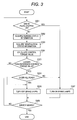
- Fig. 3 is a flowchart of a process that is executed by the brake lamp control device 10.
- the flowchart of Fig. 3 shows a process that is executed while the vehicle incorporating the brake lamp control device 10 is running.
- the brake lamp control device 10 judges whether or not the driver has stepped on the brake pedal (step S301). If judging that the driver has stepped on the brake pedal (step S301: yes), the brake lamp control device 10 moves to step S307, where it turns on the brake lamps 202. That is, the brake lamp control device 10 turns on the brake lamps 202 ordinarily.
- step S301 If judging that the driver has not stepped on the brake pedal (step S301: no), the brake lamp control device 10 causes the running status information acquiring means 102 to acquire vehicle running status information (step S302). Then the brake lamp control device 10 causes the manipulation status information acquiring means 104 to acquire vehicle manipulation status information (step S303).
- the brake lamp control device 10 causes the control torque calculating means 106 to calculate a control torque value for the motor (step S304). Calculation of a control torque value may be performed all the time while the vehicle is running.
- the regeneration lamp control means 108 judges whether or not the control torque calculated at step S304 is larger than the reference regenerative torque value (step S305). If it is judged that the control torque value is not larger than the reference regenerative torque value (step S305: no), the brake lamp control device 10 moves to step S308, where it has the turn-off state of the brake lamps 202 continued (step S308).
- step S306 the brake lamp control device 10 causes the downhill road judging means 110 to judge whether or not the road on which the vehicle is running is a downhill road (step S306). If it is judged that the road is not a downhill road (step S306: no), the regeneration lamp control means 108 turns on the brake lamps 202 (step S307). If it is judged that the road is a downhill road (step S306: yes), the regeneration lamp control means 108 has the turn-off state of the brake lamps 202 continued (step S308).
- the brake lamp control device 10 returns to step S301 to execute the following steps again until the running of the vehicle is finished (step S309: no). If it is judged that the running of the vehicle is finished (step S309: yes), the execution of the process of the flowchart is finished.
- control may be performed in such a manner that the brake lamps 202 are not turned on if deceleration that is caused by a factor (e.g., cancellation of an accelerator manipulation) other than a brake pedal manipulation is lower than or equal to X m/s 2 and that the brake lamps 202 are necessarily turned on if it is higher than Y m/s 2 (Y > X) . That is, control may be performed in such a manner that the above-described control-torque-based lighting control is performed on the brake lamps 202 only if the deceleration rate is higher than X m/s 2 and Y m/s 2 (i.e., it is in a prescribed deceleration rate range).
- a factor e.g., cancellation of an accelerator manipulation
- a step of calculating a deceleration rate is added on the "no" branch of step S301 in the flowchart of Fig. 3 .
- the brake lamps 202 are not turned on if the deceleration rate is lower than or equal to X m/s 2 , and are turned on if it is higher than Y m/s 2 .
- the process moves to step S304 if the deceleration rate is higher than X m/s 2 and lower than or equal to Y m/s 2 .
- a turn-on control is performed on the brake lamps 202 if a control torque value for the motor is on the regeneration side of and larger than the predetermined reference regenerative torque value.
- the brake lamps 202 can be turned on quickly even in the case where deceleration due to occurrence of regenerative torque is expected but an actual deceleration rate is low, whereby the deceleration can be announced with proper timing by means of the brake lamps 202, that is, nearby vehicles can be notified of the fact that the self vehicle is decelerating.
- the reference regenerative torque can be varied based on the vehicle speed, it can be changed properly in accordance with the running status of the vehicle. Furthermore, in the brake lamp control device 10, since a regenerative torque value is calculated from a vehicle speed and a status of the accelerator pedal 208 or the brake pedal 210, a regenerative torque value can be calculated correctly on the basis of a vehicle running status and manipulation status.
- the brake lamps 202 are turned off or kept off even if a calculated regenerative torque value is larger than the reference regenerative torque value. This makes it possible to turn off the brake lamps 202 in the case where the necessity of announcement using the brake lamps 202 is low as exemplified by a case of running on a long downhill road in which a deceleration state continues or deceleration does not occur though regenerative torque is being produced.
- the reference regenerative torque value is set approximately equal to a regenerative torque value corresponding to what is called engine braking.
- the brake lamps 202 can be turned on in the case where deceleration that is higher than would occur during engine braking may occur and hence it is necessary to notify nearby vehicles etc. of the deceleration.
- 10 Brake lamp control device; 102 ⁇ Running status information acquiring means; 104 ⁇ Manipulation status information acquiring means; 106 ⁇ Control torque calculating means; 108 ⁇ Lamp control means; 110 ⁇ Slope judging means; 202 ⁇ Brake lamps; 204 ⁇ Vehicle speed sensor; 205 ⁇ Shaft rotation sensors; 206 ⁇ Acceleration sensor; 212 ⁇ Mode switch; 214 ⁇ CC switch; 216 ⁇ ASL switch.
Landscapes
- Engineering & Computer Science (AREA)
- Mechanical Engineering (AREA)
- Power Engineering (AREA)
- Transportation (AREA)
- Life Sciences & Earth Sciences (AREA)
- Sustainable Development (AREA)
- Sustainable Energy (AREA)
- Lighting Device Outwards From Vehicle And Optical Signal (AREA)
- Electric Propulsion And Braking For Vehicles (AREA)
Applications Claiming Priority (2)
| Application Number | Priority Date | Filing Date | Title |
|---|---|---|---|
| JP2012224972A JP2014076715A (ja) | 2012-10-10 | 2012-10-10 | ブレーキランプ制御装置 |
| PCT/JP2013/077257 WO2014057911A1 (fr) | 2012-10-10 | 2013-10-07 | Dispositif de commande de feu stop |
Publications (2)
| Publication Number | Publication Date |
|---|---|
| EP2907698A1 true EP2907698A1 (fr) | 2015-08-19 |
| EP2907698A4 EP2907698A4 (fr) | 2016-06-29 |
Family
ID=50477378
Family Applications (1)
| Application Number | Title | Priority Date | Filing Date |
|---|---|---|---|
| EP13844855.0A Withdrawn EP2907698A4 (fr) | 2012-10-10 | 2013-10-07 | Dispositif de commande de feu stop |
Country Status (5)
| Country | Link |
|---|---|
| US (1) | US20150266415A1 (fr) |
| EP (1) | EP2907698A4 (fr) |
| JP (1) | JP2014076715A (fr) |
| CN (1) | CN104755324A (fr) |
| WO (1) | WO2014057911A1 (fr) |
Cited By (2)
| Publication number | Priority date | Publication date | Assignee | Title |
|---|---|---|---|---|
| US9266466B2 (en) | 2013-12-25 | 2016-02-23 | Mitsubishi Jidosha Kogyo Kabushiki Kaisha | Stop lamp lighting control device for electric vehicle |
| US9266467B2 (en) | 2013-12-25 | 2016-02-23 | Mitsubishi Jidosha Kogyo Kabushiki Kaisha | Stop lamp lighting control device for electric vehicle |
Families Citing this family (8)
| Publication number | Priority date | Publication date | Assignee | Title |
|---|---|---|---|---|
| JP6281483B2 (ja) * | 2014-04-17 | 2018-02-21 | 株式会社デンソー | 故障検出システム、情報処理装置、及び車両搭載装置 |
| JP6424614B2 (ja) * | 2014-12-22 | 2018-11-21 | 三菱自動車工業株式会社 | ストップランプの制御装置 |
| JP6428250B2 (ja) * | 2014-12-22 | 2018-11-28 | 三菱自動車工業株式会社 | ストップランプの制御装置 |
| CN105946700B (zh) * | 2016-05-18 | 2018-08-21 | 江苏大学 | 一种车辆制动灯辅助控制实验装置及方法 |
| US11764416B2 (en) | 2019-08-02 | 2023-09-19 | Iowa State Univerity Research Foundation, Inc. | Chemical dismantling of permanent magnet material and battery material |
| US11712972B2 (en) | 2020-09-28 | 2023-08-01 | Ford Global Technologies, Llc | Electrified vehicle one pedal drive transition control |
| JP7509043B2 (ja) | 2021-01-14 | 2024-07-02 | スズキ株式会社 | 車両の制御装置 |
| CN113147632B (zh) * | 2021-05-17 | 2023-03-07 | 中国第一汽车股份有限公司 | 一种车辆控制方法、装置、车辆及存储介质 |
Family Cites Families (17)
| Publication number | Priority date | Publication date | Assignee | Title |
|---|---|---|---|---|
| JPS63149104U (fr) * | 1987-03-18 | 1988-09-30 | ||
| JPH04358935A (ja) | 1991-06-03 | 1992-12-11 | Honda Motor Co Ltd | 減速ランプ駆動制御回路 |
| US5253929A (en) * | 1991-12-20 | 1993-10-19 | Toyota Jidosha Kabushiki Kaisha | Brake control system of electric vehicle |
| EP0770511B1 (fr) * | 1994-11-29 | 2000-03-15 | Mitsubishi Jidosha Kogyo Kabushiki Kaisha | Commande de frein pour vehicule electrique |
| JPH0937407A (ja) * | 1995-07-18 | 1997-02-07 | Toyota Motor Corp | 回生制動制御装置 |
| JPH09323585A (ja) * | 1996-06-07 | 1997-12-16 | Toyota Motor Corp | 車両用減速警告装置 |
| JP4007631B2 (ja) * | 1996-07-05 | 2007-11-14 | 日産自動車株式会社 | 制動報知灯の点灯装置 |
| US6325470B1 (en) * | 1997-10-01 | 2001-12-04 | Visteon Global Technologies, Inc. | Method and apparatus for proportioning regenerative braking |
| JP4122639B2 (ja) * | 1999-07-19 | 2008-07-23 | マツダ株式会社 | 車両の走行制御装置 |
| JP3879650B2 (ja) * | 2002-10-15 | 2007-02-14 | 日産自動車株式会社 | 車両の制御装置 |
| JP2004328991A (ja) * | 2003-04-09 | 2004-11-18 | Nissan Motor Co Ltd | 車両の左右輪駆動装置 |
| DE102008055898A1 (de) * | 2008-11-05 | 2010-05-06 | Bayerische Motoren Werke Aktiengesellschaft | Verfahren zur Ansteuerung von zumindest einer Bremsleuchte eines Fahrzeugs |
| JP4920054B2 (ja) * | 2009-03-30 | 2012-04-18 | 株式会社日立製作所 | 車両運動制御装置 |
| JP2011255795A (ja) * | 2010-06-09 | 2011-12-22 | Chugoku Electric Power Co Inc:The | 車両追突警告装置及び方法 |
| CN201745490U (zh) * | 2010-08-19 | 2011-02-16 | 奇瑞汽车股份有限公司 | 一种制动灯控制装置 |
| JP2012153294A (ja) * | 2011-01-27 | 2012-08-16 | Mitsubishi Motors Corp | 車両の制動灯制御装置 |
| JP5747804B2 (ja) * | 2011-12-09 | 2015-07-15 | トヨタ自動車株式会社 | 車両の制御装置 |
-
2012
- 2012-10-10 JP JP2012224972A patent/JP2014076715A/ja active Pending
-
2013
- 2013-10-07 EP EP13844855.0A patent/EP2907698A4/fr not_active Withdrawn
- 2013-10-07 US US14/435,089 patent/US20150266415A1/en not_active Abandoned
- 2013-10-07 WO PCT/JP2013/077257 patent/WO2014057911A1/fr active Application Filing
- 2013-10-07 CN CN201380053072.6A patent/CN104755324A/zh active Pending
Cited By (2)
| Publication number | Priority date | Publication date | Assignee | Title |
|---|---|---|---|---|
| US9266466B2 (en) | 2013-12-25 | 2016-02-23 | Mitsubishi Jidosha Kogyo Kabushiki Kaisha | Stop lamp lighting control device for electric vehicle |
| US9266467B2 (en) | 2013-12-25 | 2016-02-23 | Mitsubishi Jidosha Kogyo Kabushiki Kaisha | Stop lamp lighting control device for electric vehicle |
Also Published As
| Publication number | Publication date |
|---|---|
| EP2907698A4 (fr) | 2016-06-29 |
| WO2014057911A1 (fr) | 2014-04-17 |
| US20150266415A1 (en) | 2015-09-24 |
| CN104755324A (zh) | 2015-07-01 |
| JP2014076715A (ja) | 2014-05-01 |
Similar Documents
| Publication | Publication Date | Title |
|---|---|---|
| EP2907698A1 (fr) | Dispositif de commande de feu stop | |
| RU2634516C2 (ru) | Способ и устройство автоматического регулирования скорости транспортного средства | |
| CN107264335B (zh) | 用于控制电动车辆的转矩的系统和方法 | |
| EP3521594B1 (fr) | Dispositif de commande de véhicule | |
| CN108025750B (zh) | 车辆控制装置 | |
| CN111989247B (zh) | 用于控制机动车辆的方法 | |
| JP2022518472A (ja) | ワンペダルフィーリング機能及び/又はクリープ機能を提供する制御ユニット | |
| CN111565991B (zh) | 车辆控制方法及车辆控制系统 | |
| WO2011152128A1 (fr) | Appareil de commande de réponse de couple pour moteur électrique de véhicule | |
| KR101618453B1 (ko) | 전기동력자동차의 원-페달 운전제어방법 | |
| JP2012214181A (ja) | 車両制御システム | |
| CN110217221B (zh) | 巡航控制方法、装置、整车控制器、车辆及可读存储介质 | |
| KR20200084894A (ko) | 회생 브레이크 제어 방법 및 회생 브레이크 제어 장치 | |
| US20200377091A1 (en) | Vehicle control system | |
| JP6304082B2 (ja) | 車両の制御装置 | |
| JP2015182555A (ja) | 自動車 | |
| JP2008179232A (ja) | ハイブリッド自動車 | |
| JP2006175941A (ja) | 加減速度制御装置 | |
| JP6337664B2 (ja) | 車両の自動走行制御装置及び車両の自動走行制御方法 | |
| JP6170348B2 (ja) | 車両の回生制動制御装置 | |
| JP2007076469A (ja) | 車両の制御装置 | |
| JP2012244751A (ja) | 駆動制御装置 | |
| JPH0998509A (ja) | 電気自動車用回生制動制御装置 | |
| JP2010241245A (ja) | 車両用駆動力制御装置 | |
| JP6253646B2 (ja) | 車両制御装置 |
Legal Events
| Date | Code | Title | Description |
|---|---|---|---|
| PUAI | Public reference made under article 153(3) epc to a published international application that has entered the european phase |
Free format text: ORIGINAL CODE: 0009012 |
|
| 17P | Request for examination filed |
Effective date: 20150511 |
|
| AK | Designated contracting states |
Kind code of ref document: A1 Designated state(s): AL AT BE BG CH CY CZ DE DK EE ES FI FR GB GR HR HU IE IS IT LI LT LU LV MC MK MT NL NO PL PT RO RS SE SI SK SM TR |
|
| AX | Request for extension of the european patent |
Extension state: BA ME |
|
| DAX | Request for extension of the european patent (deleted) | ||
| RA4 | Supplementary search report drawn up and despatched (corrected) |
Effective date: 20160531 |
|
| RIC1 | Information provided on ipc code assigned before grant |
Ipc: B60Q 1/44 20060101AFI20160523BHEP Ipc: B60L 7/10 20060101ALI20160523BHEP Ipc: B60L 3/00 20060101ALI20160523BHEP |
|
| STAA | Information on the status of an ep patent application or granted ep patent |
Free format text: STATUS: THE APPLICATION IS DEEMED TO BE WITHDRAWN |
|
| 18D | Application deemed to be withdrawn |
Effective date: 20170103 |