EP2906813B1 - Dispositif d'alimentation de combustible - Google Patents
Dispositif d'alimentation de combustible Download PDFInfo
- Publication number
- EP2906813B1 EP2906813B1 EP13776477.5A EP13776477A EP2906813B1 EP 2906813 B1 EP2906813 B1 EP 2906813B1 EP 13776477 A EP13776477 A EP 13776477A EP 2906813 B1 EP2906813 B1 EP 2906813B1
- Authority
- EP
- European Patent Office
- Prior art keywords
- fuel
- volume
- tank
- return
- pot
- Prior art date
- Legal status (The legal status is an assumption and is not a legal conclusion. Google has not performed a legal analysis and makes no representation as to the accuracy of the status listed.)
- Not-in-force
Links
Images


Classifications
-
- F—MECHANICAL ENGINEERING; LIGHTING; HEATING; WEAPONS; BLASTING
- F02—COMBUSTION ENGINES; HOT-GAS OR COMBUSTION-PRODUCT ENGINE PLANTS
- F02M—SUPPLYING COMBUSTION ENGINES IN GENERAL WITH COMBUSTIBLE MIXTURES OR CONSTITUENTS THEREOF
- F02M37/00—Apparatus or systems for feeding liquid fuel from storage containers to carburettors or fuel-injection apparatus; Arrangements for purifying liquid fuel specially adapted for, or arranged on, internal-combustion engines
- F02M37/02—Feeding by means of suction apparatus, e.g. by air flow through carburettors
- F02M37/025—Feeding by means of a liquid fuel-driven jet pump
-
- F—MECHANICAL ENGINEERING; LIGHTING; HEATING; WEAPONS; BLASTING
- F02—COMBUSTION ENGINES; HOT-GAS OR COMBUSTION-PRODUCT ENGINE PLANTS
- F02M—SUPPLYING COMBUSTION ENGINES IN GENERAL WITH COMBUSTIBLE MIXTURES OR CONSTITUENTS THEREOF
- F02M37/00—Apparatus or systems for feeding liquid fuel from storage containers to carburettors or fuel-injection apparatus; Arrangements for purifying liquid fuel specially adapted for, or arranged on, internal-combustion engines
- F02M37/04—Feeding by means of driven pumps
- F02M37/08—Feeding by means of driven pumps electrically driven
- F02M37/10—Feeding by means of driven pumps electrically driven submerged in fuel, e.g. in reservoir
- F02M37/106—Feeding by means of driven pumps electrically driven submerged in fuel, e.g. in reservoir the pump being installed in a sub-tank
Definitions
- the invention relates to a fuel supply device for an internal combustion engine, in particular of a vehicle, comprising a fuel tank with a tank volume, a feed line for directing the fuel from the fuel tank to the internal combustion engine, a return line for the delivery of unused fuel from the internal combustion engine to the fuel tank, a fuel pump, which is arranged in the flow, inside the fuel tank, a flow line of the flow and / or a return line of the return and arranged in the fuel tank surge pot whose pot volume is separated from the tank volume of the fuel tank, wherein the surge chamber is connected to the suction side of the fuel pump.
- the invention relates to a fuel supply device for an internal combustion engine, in particular of a vehicle, comprising a fuel tank with a tank volume, a lead for directing the fuel from the fuel tank to the internal combustion engine, a return line for conducting unused fuel from the internal combustion engine to the fuel tank, a fuel pump , which is arranged in the flow, arranged in the fuel tank baffle whose pot volume is separated from the tank volume of the fuel tank and which is connected to the suction side of the fuel pump, and a suction jet pump and / or a check valve, which are arranged in the fuel tank and the Fill the swirl pot to connect the tank volume with the pot volume, the suction jet pump is connected to supply a driving current via a feed line to the flow, in particular with the flow line.
- a fuel supply device with a flow, a return, a swirl pot and a suction jet pump for filling the swirl pot is from the document DE 44 26 685 A1 known.
- the disclosed swirl pot consists of two spatially separate chambers, wherein in the first chamber, the suction jet pump is arranged and the second chamber is associated with the suction side of a fuel pump arranged in the flow.
- the suction jet pump fills the second chamber, wherein both chambers are also connected via an overflow line.
- the document also shows an open connection of the return line with the swirl pot.
- DE 195 41 723 A1 and WO 2009/062805 A1 show a fuel supply device with a flow, a return and a swirl pot, in which the return ends open in the swirl pot.
- Fuel supply devices with a pressure-limiting valve arranged in the supply line are known from the documents DE 10 2008 044 904 A1 and DE 10 2004 061 874 A1 known. These documents further disclose a fuel tank in which a swirl pot is arranged and in which the suction side of the fuel pump is associated with the swirl pot.
- a fuel supply device in which no swirl pot, but a fuel accumulator associated with the pump inlet is provided, is in the document DE 196 25 629 A1 disclosed. This fuel accumulator is arranged at a filter positioned between the pump inlet and the tank volume.
- the extraction line is expediently arranged at the bottom of the fuel tank, which allows a nearly complete emptying of the fuel tank.
- the problem arises that due to cornering of the vehicle and bumps the mouth of the extraction line is at least temporarily not surrounded by fuel. The result is that in such a case, air or an air-fuel vapor mixture is sucked.
- a baffle pot also called jam pot and to ensure that there is always a certain storage volume in this. A few liters of fuel are enough.
- the decisive factor is the filling level of the fuel.
- the pot volume of the swirl pot is maintained by a pump.
- a pump As a rule, it is an ejector pump, ie a pump operating on the Venturi principle.
- Such pumps are usually driven by the flow or the return flow of the fuel.
- a fuel filter is provided in the flow between the fuel tank and the internal combustion engine.
- the fuel filter frees the fuel from solid particles.
- Unfiltered fuel may contain various types of contaminants, such as pieces of paint or debris that have entered the tank when filled, as well as rust formed by moisture in the steel tanks or paraffins crystallized in the cold fuel. If these substances are not removed before the fuel enters the engine, premature wear and defects in the fuel pump and injection system are likely to be caused by both blockage of nozzles and wear-promoting action of the particles.
- the fuel heated in the internal combustion engine is returned to the fuel tank and / or the fuel filter.
- the fuel heated in the internal combustion engine is returned to the fuel tank and / or the fuel filter.
- the invention has the object of providing an optimized fuel supply device.
- the starting point of the invention is a fuel supply device for an internal combustion engine, comprising a fuel tank with a tank volume, a feed line for the fuel from the fuel tank to the internal combustion engine, a return line for the delivery of unused fuel from the internal combustion engine to the fuel tank, a fuel pump, which in the Forward flow is arranged inside the fuel tank, a supply line of the flow and / or return line of the return, a pot arranged in the fuel tank, whose pot volume is separated from the tank volume of the fuel tank, wherein the surge chamber is connected to the suction side of the fuel pump, wherein a suction jet pump is arranged in the swirl pot, which includes a check valve for connecting the swirl pot with the pot volume.
- the return is associated with the line of unused fuel from the engine to the fuel tank of the suction side of the fuel pump and the suction jet pump is connected to supply a driving current via a feed line to the flow and / or the return , wherein the feed line is connected by means of a controllable depending on the volume flow ratio between flow and return control valve with the flow and / or the return.
- the invention thus consists, in particular, in that the feed line of the suction jet pump is connected to the supply by means of a control valve controllable in dependence on the volume flow ratio between supply and return and / or the suction jet pump is oriented with its conveying direction parallel to the vertical, in particular to the vertical vehicle axis.
- a control valve controllable in dependence on the volume flow ratio between supply and return and / or the suction jet pump is oriented with its conveying direction parallel to the vertical, in particular to the vertical vehicle axis.
- the use of the fuel from the supply and / or the return means that the used propellant flow is replaced by unfiltered fuel and increases the proportion of paraffins and particles in the flow.
- the targeted control of the suction jet pump as a function of the volume flow ratio between flow and return it is possible at least temporarily to reduce the delivery capacity of the suction jet pump or shut off the suction jet pump at a high return rate.
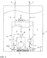
- the suction jet pump is oriented in the aforementioned embodiment with its conveying direction parallel to the vertical, in particular to the vertical axis of the vehicle. ( Figure 5 )
- the suction jet pump is oriented horizontally, whereby the conveying direction of the suction jet pump is oriented parallel to the bottom of the swirl pot.
- the vertical arrangement of the suction jet pump in particular by the vertical arrangement of mixing tube and diffuser, it is possible to achieve a radially symmetric promotion. Since the intake and delivery of a vertically oriented suction jet pump from the gravity field is unaffected, the flow through the mixing tube and especially the diffuser is uniform and free of one-sided turbulence. In the fuel tank, in particular within the swirl pot, the horizontal space is limited. Therefore, in contrast to the horizontally arranged suction jet pumps known from the prior art, the vertical orientation of the suction jet pump makes it possible to design the mixing tube and above all the diffuser almost as long as desired. The length of the suction jet pump and the avoidance of turbulence in the suction jet pump improve their efficiency. A suction jet pump with better efficiency requires less drive current to convey a given fill volume. The reduction of the driving volume requirement also reduces the proportion of paraffins and particles in the forerun, especially at low ambient temperatures.
- the suction jet pump is arranged in the surge pot, in particular at the bottom of the surge pot. This makes it possible to perform the ejector with the surge pot as an assembly, which reduces the number of parts to be assembled. Furthermore, so the entire height of the swirl pot can be used for the formation of the suction jet pump. Moreover, it is possible to arrange the suction jet pump directly above a check valve positioned in the bottom of the swirl pot and connecting the swirl pot to the tank volume. According to a further embodiment, the check valve in the suction jet pump is arranged. The check valve is designed as a an opening in the bottom of the swirl pot occlusive mushroom valve.
- the supply valve may for example be designed as a solenoid valve, which closes when the electric motor of the fuel pump.
- the supply valve is a simple mechanical mushroom valve.
- the invention for achieving the object is that a fuel supply device is provided, in which the return of the suction side of the fuel pump is associated.
- the inventive arrangement of the return since the fuel returned by the internal combustion engine has already passed through the fuel filter and thus no paraffin particles even at low fuel temperature, it is possible by the inventive arrangement of the return, to dispense with a heater for heating the fuel.
- the recirculated and freed from particles and paraffins fuel is no further burden for the fuel filter.
- the fuel pump is for example a centrifugal pump and preferably driven by an electric motor. The fuel pump delivers about 60 liters of fuel per hour while the engine consumes about 5 liters of fuel over the same period.
- the return in particular the return line, opens close to the inlet of the fuel pump in the surge chamber and / or is connected to the suction side of the fuel pump.
- the return is connected to the suction side of the fuel pump, no open connection between the return and swirl pot, as for example in the in the document DE 44 26 685 A1 the solution explained is the case.
- the fuel pump comprises a suction line, which is connected on the one hand with the pump chamber of the fuel pump and on the other hand with a arranged in the swirl pot filter.
- the return in particular the return line, connected to the filter of the fuel pump and / or to the suction line of the fuel pump.
- the filter screen has a mesh size of 100 to 300, preferably 200 micrometers. With a high content of paraffin particles in the unfiltered fuel, it is possible that the pores of the filter screen are narrowed.
- the pressure of the return directly into the Filter filter flowing filtered fuel penetrates just as little unfiltered fuel through the filter, as was consumed by the internal combustion engine. This means that on the one hand, the particle load remains low and on the other hand, the fuel heats up faster in the flow. Due to the increased fuel temperature in the flow, the paraffin particles can be dissolved on the fuel filter.
- the suction line is as short as possible. This is achieved by arranging the fuel pump in the fuel tank, preferably in the swirl pot.
- the fuel supply device also includes a pressure relief valve for controlling the pressure in the flow. It is advantageous that the pressure relief valve is connected on the one hand with the flow and on the other hand with the return, in particular with the return line. If the pressure in the flow exceeds a limit value, a pressure reduction in the flow is required for operational safety. This pressure reduction is usually carried out by a pressure relief valve, which opens the flow to the tank volume and / or the pot volume. The flow contains a very high proportion of filtered fuel through the connection of the return to the suction side of the fuel pump. By connecting the pressure limiting valve on the one hand to the flow and on the other hand to the return, it is possible to minimize a loss of the filtered fuel.
- a further development of the fuel supply device comprises a buffer store arranged downstream of the pressure relief valve in the return line. This serves to receive the fuel from the opening pressure relief valve with a full return.
- the fuel supply device comprises a temperature limiting valve.
- This temperature limiting valve serves, in particular at high heat output of the internal combustion engine and / or at high ambient temperature, to limit the fuel temperature in particular in the flow.
- the temperature limiting valve in the return in particular in the return line, is arranged.
- the temperature limiting valve is preferably designed as a mechanical and / or hydraulic and / or electrical, self-regulating and / or controllable three-way valve.
- the control of the temperature limiting valve by means of a bimetal, also called crackling frog, or by means of a Wachsdehnelements. It is both a partial as also a complete interruption of the connection of the return to the suction side of the fuel pump possible.
- the temperature limiting valve connects the return line, in particular the return line, as a function of the temperature of the fuel in the return to the tank volume and / or the pot volume and / or the suction side of the fuel pump. If the fuel temperature at the temperature limiting valve exceeds a limit value, for example 303 degrees Kelvin, then at least a partial flow of the fuel returned by the internal combustion engine is released freely into the swirl pot. Here, the warm fuel from the recirculation mixes with the unfiltered fuel and cools down. Since this control is only at high temperatures, where the unfiltered fuel contains little or no paraffin particles, the proportion of filtered fuel in the flow can be lower or completely eliminated.
- a limit value for example 303 degrees Kelvin
- the temperature limiting valve is preferably arranged in the return flow in the flow direction of the fuel behind the pressure relief valve.
- An increase in the fuel temperature in the flow is also possible by the fuel pump is specifically placed in an energetically unfavorable state.
- an electric centrifugal pump is operated speed-controlled with maximum energization of the stator coils. This is possible when using an electronically commutated motor (EC motor), since in such an engine, the speed and the torque can be controlled independently.
- EC motor electronically commutated motor
- the excess electrical power is converted directly into heat in the coils and taken up in the pump room of the fuel, for example.
- the fuel supply device shown so far supplies an internal combustion engine.
- a heater is installed in the manner of a heater.
- the invention thus also relates to a fuel supply device for supplying an internal combustion engine and a heating device.
- the known solutions of fuel supply devices are characterized by a fuel tank that includes a tank volume, a conduit connecting the fuel tank to the heater and including an intake pipe disposed in the fuel tank, and a sump, which is provided for receiving the suction line, wherein the sump is disposed in the fuel tank and / or in a surge pot of the fuel tank.
- the publication DE 10 2005 061 604 A1 discloses a fuel supply device for removing fuel from the fuel tank of a motor vehicle for an auxiliary heater of the motor vehicle, in particular for a parking heater.
- the fuel supply device has a collecting container which is accommodated in the fuel tank, in particular in the surge tank of the fuel tank, and is assigned exclusively to the auxiliary heater.
- pamphlets DE 10 2005 000 729 A1 and DE 10 2005 059 457 A1 show fuel supply devices with a collecting vessel arranged in the swirl pot.
- a fuel supply device in which for the removal of fuel from the fuel tank of a motor vehicle for a heater a suction in a arranged on the swirl pot guide is used.
- the fuel for the combustion type heater has been taken out with a pipe from a fuel tank of a motor vehicle.
- this has the disadvantage that, especially with a low filling level of the fuel in the fuel tank, the fuel can slosh away from an intake pipe.
- bubbles or foams contained in the fuel which are predominantly located on the fuel surface, are sucked into the intake manifold.
- the fuel is removed from the fuel tank by means of a built-in swirl pot.
- baffles are arranged on the fuel tank bottom and are filled, for example, by overflowing the fuel through the top of the baffle through a valved orifice in the bottom of the baffle and through a suction jet pump.
- the swirl pot stores fuel even if the fuel spills in the tank. This ensures that fuel is present at the intake pipe for the fuel supply of the internal combustion engine in all driving situations.
- a significant improvement in the operation of the heater was achieved in that the fuel is removed from the swirl pot, since the fuel spills away less.
- the pot volume of the swirl pot is sufficiently sized for a short-term operation of the internal combustion engine. So it is possible, for example, to go to another gas station.
- a swirl pot emptied by a heater can lead to the fuel no longer being available for the start of the internal combustion engine, or the internal combustion engine sucking in air.
- An optimized fuel supply device which makes it possible for the heating device and the internal combustion engine to be supplied with fuel from a common fuel tank independently of one another.
- the fuel supply device comprises a heating device for supplying the internal combustion engine, in particular a parking heater of a motor vehicle.
- a conduit connecting the fuel tank to the heater and including an intake passage disposed in the fuel tank, and a sump provided for receiving the intake passage, the sump being disposed in the surge tank of the fuel tank.
- the collecting container also has a valve device, which is set up to connect the collecting volume of the collecting container to the tank volume of the fuel tank. This makes it possible to fill the sump from the tank volume without emptying the swirl pot thereby. This is made possible in particular by the fact that the collecting container is assigned exclusively to the heating device.
- the collecting container includes a collecting volume, which is separated from the pot volume of the swirl pot and / or from the tank volume of the fuel tank.
- the valve device is preferably designed as a pressure relief valve which opens to the collecting volume of the collecting container, for example as a mushroom valve. In a control operation of the internal combustion engine, in which the continuous filling of the surge chamber is ensured, the collecting container can also be connected to the pot volume.
- the valve device is designed, for example, as a three-way valve.
- the swirl pot is arranged in the fuel tank and the pot volume of the swirl pot is separated from the tank volume of the fuel tank. This makes it possible to independently supply the heating device and the internal combustion engine with fuel from a common fuel tank.
- the collecting container is connected to the bottom of the swirl pot. This makes it possible to arrange the valve device directly in the common bottom of swirl pot and reservoir. For a simple manufacture of the collecting container and a small number of parts to be assembled, it is dispensable that the collecting container with the swirl pot is produced as an assembly. Preferably the collecting container with the swirl pot is in one piece urgeformt.
- the direct connection of the collecting container to the tank volume shortens the supply line to the collecting container and thus the number and complexity of the parts to be installed. In addition, so the volume of the sump can be maximized. It is favorable that the container bottom of the collecting container is executed at least in sections konturb réelle with the bottom of the swirl pot.
- the collection volume is at least 0.03 liters.
- the largest possible collecting volume is also available in that the inlet opening of the suction line is arranged on the container bottom of the collecting container. This arrangement is possible only by the inventive separation of the collection volume of the pot volume and the connection of the collection volume with the tank volume.
- the sump has an opening positioned at one end remote from the bottom of the baffle and / or at an end remote from the bottom of the fuel tank.
- This opening is therefore in the gravitational field at the top of the collection container.
- the collecting container is filled by an overflow of the fuel from the tank volume and / or pot volume in the collecting volume.
- the opening is connected to the pot volume of the swirl pot and / or the tank volume of the fuel tank.
- the collecting volume is filled from the tank volume at standstill of the internal combustion engine via the valve device and during operation of the internal combustion engine and / or during operation of the surge pump via the pot volume.
- a favorable embodiment is that the collecting container is extended over at least two thirds of the height of the swirl pot. On the one hand, this makes it possible to obtain a large collecting volume; on the other hand, if there is a lack of further filling of the collecting container and simultaneous operation of the heating device, sufficient fuel remains in the collecting container for a restart of the internal combustion engine.
- connection of the pot volume with the tank volume is independent of the connection of the collecting volume with the tank volume. It is favorable that the removal point provided for filling the pot volume in the tank volume in the gravitational field further down, that is closer to the bottom of the fuel tank, is arranged as the connection of the collecting volume with the tank volume.
- FIG. 1 shows a schematic representation of a fuel supply device 1 for an internal combustion engine 2.
- the fuel supply device 1 comprises a fuel tank 3 with a tank volume 4, a flow 5 for directing the fuel from the fuel tank 3 to the internal combustion engine 2, a return line 6 for conducting unused fuel from the Internal combustion engine 2 to the fuel tank 3 and a fuel pump 7, which is arranged in the flow 5.
- the supply line 5 has a supply line 8 and the return line 6 has a return line 9.
- the fuel supply device 1 further comprises a surge pot 10, which is arranged in the fuel tank 3.
- the swirl pot 10 includes a pot volume 11 which is separate from the tank volume 4 of the fuel tank 3.
- the suction side of the fuel pump 7 is connected to the pot volume 11, the return 6 of the suction side is assigned to the fuel pump 7.
- a fuel filter 13 is arranged between the fuel pump 7 and the internal combustion engine 2.
- the further embodiment of the fuel supply device 1, in particular of the fuel tank 3, the FIGS. 2 to 6 be removed.
- a supply valve 31 is provided in this.
- the supply valve 31 is a mechanical mushroom valve,
- the Figures 2 and 3 show an enlarged section of the fuel tank 3 in FIG. 1 shown fuel supply device 1.
- the fuel pump 7 is arranged.
- the fuel pump 7 has a suction line 14, which is connected on the one hand with the pump chamber of the fuel pump 7 and on the other hand with the filter screen 12.
- the fuel supply device 1 comprises a pressure limiting valve 15 for regulating the pressure in the supply line 5.
- the pressure limiting valve 15 is connected on the one hand to the supply line 5 and on the other hand to the return line 6.
- the pressure relief valve 15 is connected to the flow line 8 and the return line 9.
- the pressure relief valve 15 is a spring-loaded check valve in the preferred embodiment shown.
- the fuel supply device 1 comprises a temperature limiting valve 16.
- the temperature limiting valve 16 is arranged in the return line 6, in particular in the return line 9.
- the temperature limiting valve 16 is preferably designed as a two-way three-way valve.
- the temperature limiting valve 16 connects the return line 6 in dependence of the fuel temperature in the return line 6 via an outlet 17 with the pot volume 11 or with the suction side of the fuel pump 7.
- the temperature limiting valve 16 is arranged in the return line 9 in the flow direction of the fuel after the pressure relief valve 15.
- FIG. 2 shows a first embodiment of the fuel supply device 1.
- the return line 9 of the return line 6 with the filter screen 12 of the fuel pump 7 is connected.
- the return line 9 ends at or in the filter screen 12.
- the temperature limiting valve 16 connects the return line 6 with the filter screen 12 in at least one switching state.
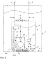
- FIG. 3 shows a second embodiment of the fuel supply device 1.
- the return line 9 is connected to the suction line 14 of the fuel pump 7.
- the return line 9 ends at its mouth in the suction line 14.
- the temperature limiting valve 16 connects depending on the fuel temperature in the return line 6, the return line 6 with the suction line 14 of the fuel pump. 7
- FIGS. 4 to 6 show a suction jet pump 18 a in FIG. 1
- a fuel jet pump, 18 is used to deliver fuel from the tank volume 4 in the swirl pot 10.
- the suction jet pump 18 is driven by a partial flow of the flow 5.
- the feed line 19 connects the suction jet pump, 18 with the supply line 8.
- the drive current is in the suction jet pump 18 by a in FIG. 6 shown nozzle 20 pressed and thereby greatly accelerated.
- the motive flow passes through a mixing tube 21 and then passes into a diffuser 22. In the diffuser 22, the motive flow expands again, thus creating a negative pressure in the mixing tube 21.
- a feed 23 is connected. Due to the negative pressure in the mixing tube 21, fuel is supplied from the inlet 23 through the mixing tube 21 and the diffuser 22.
- the inlet 23 is associated with the bottom 24 of the swirl pot 10.
- an opening 25 is introduced, which connects the pot volume 11 with the tank volume 4.
- the opening 25 is associated with a designed as a mushroom check valve 28.
- a further check valve designated as a supply valve 31 is provided in the surge chamber 10.
- the supply valve 31 is a mechanical mushroom valve.
- FIG. 4 shows in an enlarged section of the fuel tank 3, a third embodiment of the in FIG. 1 shown fuel supply device 1.
- a suction jet pump 18 is arranged in the swirl pot 10 of the fuel tank 3.
- the suction jet pump, 18 is connected via the feed line 19 and arranged in the flow line 8 control valve 29 to the flow 5.
- the size of the drive current is adjusted and thus affects the performance of the ejector 18.
- the suction jet pump 18 is horizontally aligned in the swirl pot 10.
- the conveying direction of the suction jet pump 18 is oriented parallel to the bottom 24 of the swirl pot 10.
- FIG. 5 shows in an enlarged section of the fuel tank 3, a fourth embodiment of the in FIG. 1 shown fuel supply device 1.
- the suction jet pump 18 vertically aligned in the swirl pot 10.
- the conveying direction of the suction jet pump 18 is oriented perpendicular to the bottom 24 of the swirl pot 10.
- the control valve 29 is disposed in a housing 30 of the fuel pump 7.
- FIG. 7 shows a fuel supply device 1 for supplying an internal combustion engine 2 and a heater 300, in particular a parking heater of a motor vehicle, with fuel from a fuel tank 3.
- the fuel supply device 1 comprises at least the fuel tank 3, which includes a tank volume 4, and a fuel tank 3 with the heater 300 connecting line 60, which includes a arranged in the fuel tank 3 intake 70.
- the fuel supply device 1 further comprises a collecting container 80, which is provided for receiving the intake line 70, wherein the collecting container 80 is arranged in a surge pot 10 of the fuel tank 3.
- a fuel pump 7 is arranged in the surge pot 10, which conveys fuel to the internal combustion engine 2 via a supply line 5.
- the swirl pot 10 includes a pot volume 11 a.
- the pot volume 11 is separated from the tank volume 4.
- the surge pot 10 has at least one inlet device 31.
- the feed device 31 is, for example, a check valve arranged in the boundary surface 150 of the swirl pot 10 and designed as a mushroom valve.
- the collecting container 80 has a valve device 160. This valve device 160 is designed as a check valve, preferably in the design of a mushroom valve. By means of the valve device 160, a collecting volume 170 of the collecting container 80 can be connected to the tank volume 4 of the fuel tank 3.
- the valve device 160 for connecting the collecting volume 170 with the tank volume 4 is arranged in the gravity field at the same height or higher than the inlet device 31 for connecting the pot volume 11 with the tank volume 4.
- the collecting volume 170 of the collecting container 80 is assigned exclusively to the heating device 300.
- the heater 300 has a pumping device 180.
- the heater 300 further includes a combustion apparatus 190 in which the fuel is burned.
- the collection container 80 has a in the FIG. 2 shown bottom 24 of the swirl pot 10 or on a bottom 27 of the fuel tank 3 side facing away from a particular permanent opening 230th
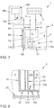
- FIG. 8 shows a sectional and enlarged view of a section of the in FIG. 1
- the fuel tank 80 is connected to the bottom 24 of the swirl pot 10, wherein the container bottom 210 of the collecting container 80 is executed at least partially konturbmony with the bottom 24 of the swirl pot 10.
- the valve device 160 is arranged in an opening of the container bottom 210.
- the bottom 24 or the container bottom 210 is at a distance from the base 27 of the fuel tank 3. This distance serves to ensure the inflow of fuel to the valve device 160.
- the suction line 70 arranged in the collecting container 80 has an inlet opening 230. This inlet opening 230 is assigned to the container floor 210, wherein the distance of the inlet opening 230 from the container floor 210 is smaller than five times the diameter of the suction line 70.
- the invention also relates to a fuel supply device 1, whose features in the description of the FIGS. 1 to 6 and the description of the FIGS. 7 and 8 are formed in combination.
- a fuel supply device 1 is formed for an internal combustion engine 2, the fuel tank 3 with a tank volume 4, and a flow 5 for guiding the fuel from the fuel tank 3 to the internal combustion engine 2, and the one Return line 6 for conducting unused fuel from the internal combustion engine 2 to the fuel tank 3, and the one fuel pump 7, which is arranged in the flow 5, and the inside of the fuel tank 3, a flow line 8 of the flow 5 and / or a return line 9 of the Return passage 6, and which comprises a arranged in the fuel tank 3 swirl pot 10 whose pot volume 11 is separated from the tank volume 4 of the fuel tank 3, wherein the swirl pot 10 is connected to the suction side of the fuel pump 7.
- the fuel supply device 1 for supplying the internal combustion engine 2 and the heating device 300 further comprises a suction jet pump 18 and / or a check valve 28 which are arranged in the fuel tank 3 and to fill the surge tank 10, the tank volume 4 with the pot volume 11 connect, wherein the suction jet pump 18th for supplying a drive current via a feed line 19 to the flow 5 and / or the return line 6 is connected, wherein the feed line 19 by means of a controllable function of the volume flow ratio between flow 5 and return 6 control valve 29 with the flow 5 and / or the return 6 is connected and / or the suction jet pump 18 is oriented with its conveying direction parallel to the vertical, in particular to the vertical vehicle axis.
Landscapes
- Engineering & Computer Science (AREA)
- Chemical & Material Sciences (AREA)
- Combustion & Propulsion (AREA)
- Mechanical Engineering (AREA)
- General Engineering & Computer Science (AREA)
- Cooling, Air Intake And Gas Exhaust, And Fuel Tank Arrangements In Propulsion Units (AREA)
Claims (15)
- Dispositif d'alimentation en carburant (1) pour un moteur à combustion interne (2), comprenant un réservoir de carburant (3) avec un volume de réservoir (4), une conduite d'arrivée (5) pour conduire le carburant du réservoir de carburant (3) au moteur à combustion interne (2), une conduite de renvoi (6) pour conduire le carburant inutilisé du moteur à combustion interne (2) au réservoir de carburant (3), une pompe à carburant (7), qui est disposée dans la conduite d'arrivée (5), à l'intérieur du réservoir de carburant (3) une conduite de départ (8) de la conduite d'arrivée (5) et/ou une conduite de retour (9) de la conduite de renvoi (6), un réservoir interne (10) disposé dans le réservoir de carburant (3), dont le volume interne (11) est séparé du volume de réservoir (4) du réservoir de carburant (3), dans lequel le réservoir interne (10) est raccordé au côté d'aspiration de la pompe à carburant (7), et une pompe à éjecteur (18) est disposée dans le réservoir interne (10), qui comprend un clapet antiretour (28) pour la communication du réservoir interne (10) avec le volume interne (11), caractérisé en ce que la conduite de renvoi (6) pour conduire le carburant inutilisé du moteur à combustion interne (2) au réservoir de carburant (3) est associée au côté d'aspiration de la pompe à carburant (7) et la pompe à éjecteur (18) pour l'alimentation avec un courant de propulsion est raccordée par une conduite d'alimentation (19) à la conduite d'arrivée (5) et/ou à la conduite de renvoi (6), dans lequel la conduite d'alimentation (19) est raccordée à la conduite d'arrivée (5) et/ou à la conduite de renvoi (6) au moyen d'une soupape de régulation (29) pouvant être commandée en fonction du rapport des flux volumétriques entre la conduite d'arrivée (5) et la conduite de renvoi (6).
- Dispositif d'alimentation en carburant (1) selon la revendication 1, caractérisé en ce que la pompe à éjecteur (18) est disposée dans le réservoir interne (10), en particulier sur le fond (24) du réservoir interne (10).
- Dispositif d'alimentatian en carburant (1) selon la revendication 1 ou 2, caractérisé en ce que la pompe à éjecteur (18) est orientée avec sa direction de transport parallèle à la verticale, en particulier à l'axe vertical du véhicule, ou est orientée horizontalement, la direction de transport de la pompe à éjecteur (18) étant ainsi orientée parallèlement au fond (24) du réservoir interne (10).
- Dispositif d'alimentation en carburant (1) selon la revendication 1, caractérisé en ce que le clapet antiretour (28) est disposé dans le fond (24) du réservoir interne (10) et/ou dans la pompe à éjecteur (18).
- Dispositif d'alimentation en carburant (1) selon la revendication 1, caractérisé en ce que la conduite de renvoi (6), en particulier la conduite de retour (9), débouche dans le réservoir interne (10) à proximité de l'entrée de la pompe à carburant (7) et/ou est raccordée au côté d'aspiration de la pompe à carburant (7).
- Dispositif d'alimentation en carburant (1) selon la revendication 5, caractérisé en ce que la pompe à carburant (7) présente une conduite d'aspiration (14), qui est raccordée d'une part à la chambre de pompe de la pompe à carburant (7) et d'autre part à un tamis de filtre (12) disposé dans le réservoir interne (10), dans lequel la conduite de renvoi (6), en particulier la conduite de retour (9), est raccordée au tamis de filtre (12) de la pompe à carburant (7) et/ou à la conduite d'aspiration (14) de la pompe à carburant (7).
- Dispositif d'alimentation en carburant (1) selon la revendication 1, caractérisé en ce que le dispositif d'alimentation en carburant (1) comprend une soupape de limitation de pression (15) pour la régulation de la pression dans la conduite d'arrivée (5), qui est raccordée d'une part à la conduite d'arrivée (5) et d'autre part à la conduite de renvoi (6), en particulier à la conduite de départ (8) et/ou à la conduite de retour (9).
- Dispositif d'alimentation en carburant (1) selon la revendication 1, caractérisé en ce que le dispositif d'alimentation en carburant (1) comprend une soupape de limitation de la température (16), qui est disposée dans la conduite de renvoi (6), en particulier dans la conduite de retour (9).
- Dispositif d'alimentation en carburant (1) selon la revendication 8, caractérisé en ce que la soupape de limitation de la température (16) relie la conduite de renvoi (6), en particulier la conduite de retour (9), en fonction de la température du carburant dans la conduite de renvoi (6), au volume de réservoir (4) et/ou au volume interne (11) et/ou au côté d'aspiration de la pompe à carburant (7).
- Dispositif d'alimentation en carburant (1) selon la revendication 8, caractérisé en ce que la soupape de limitation de la température (16) est disposée dans la conduite de renvoi (6), après la soupape de limitation de la pression (15) dans la direction d'écoulement du carburant.
- Dispositif d'alimentation en carburant (1) selon la revendication 1, caractérisé par un dispositif de chauffage (300) et une conduite (60) reliant le réservoir de carburant (3) au dispositif de chauffage (300), qui comprend une conduite d'aspiration (70) disposée dans le réservoir de carburant (3), et un réservoir de collecte (80) associé exclusivement au dispositif de chauffage (300), qui est disposé dans le réservoir interne (10) du réservoir à carburant (3), et dont le volume de collecte (170) est séparé du volume interne (11) du réservoir interne (10) et/ou du volume de réservoir (4) du réservoir de carburant (3), et qui est prévu pour contenir la conduite d'aspiration (70).
- Dispositif d'alimentation en carburant (1) selon la revendication 11, caractérisé en ce que le réservoir de collecte (80) présente un dispositif de soupape (160), qui est conçu pour le raccordement du volume de collecte (170) du réservoir de collecte (80) au volume de réservoir (4) du réservoir de carburant (3), dans lequel le dispositif de soupape (160) pour le raccordement du volume de collecte (170) au volume de réservoir (4) est disposé dans le champ de gravitation à la même hauteur ou plus haut que le dispositif d'arrivée (31) pour le raccordement du volume interne (11) au volume de réservoir (4).
- Dispositif d'alimentation en carburant (1) selon la revendication 11, caractérisé en ce que le réservoir de collecte (80) est raccordé à un fond (24) du réservoir interne (10) et un fond de réservoir (210) du réservoir de collecte (80) est configuré de façon à épouser au moins en partie le contour du fond (24) du réservoir interne (10).
- Dispositif d'alimentation en carburant (1) selon la revendication 13, caractérisé en ce que le réservoir de collecte (80) présente sur un côté situé à l'opposé du fond (24) du réservoir interne (10) et/ou d'un fond (27) du réservoir de carburant (3) une ouverture permanente (23), de telle manière que le volume de collecte (170) du réservoir de collecte (80) soit raccordé par l'ouverture (23) au volume interne (11) du réservoir interne (10) et/ou au volume de réservoir (4) du réservoir de carburant (3).
- Dispositif d'alimentation en carburant (1) selon la revendication 11, caractérisé en ce que le réservoir de collecte (80) s'étend sur au moins deux tiers de la hauteur du réservoir interne (10).
Applications Claiming Priority (3)
| Application Number | Priority Date | Filing Date | Title |
|---|---|---|---|
| DE201210020321 DE102012020321A1 (de) | 2012-10-13 | 2012-10-13 | Kraftstoffversorgungseinrichtung |
| DE201210020396 DE102012020396A1 (de) | 2012-10-18 | 2012-10-18 | Kraftstoffversorgungseinrichtung |
| PCT/EP2013/071296 WO2014057093A1 (fr) | 2012-10-13 | 2013-10-11 | Système d'alimentation en carburant |
Publications (2)
| Publication Number | Publication Date |
|---|---|
| EP2906813A1 EP2906813A1 (fr) | 2015-08-19 |
| EP2906813B1 true EP2906813B1 (fr) | 2018-04-18 |
Family
ID=49354661
Family Applications (1)
| Application Number | Title | Priority Date | Filing Date |
|---|---|---|---|
| EP13776477.5A Not-in-force EP2906813B1 (fr) | 2012-10-13 | 2013-10-11 | Dispositif d'alimentation de combustible |
Country Status (3)
| Country | Link |
|---|---|
| EP (1) | EP2906813B1 (fr) |
| CN (1) | CN104838128B (fr) |
| WO (1) | WO2014057093A1 (fr) |
Families Citing this family (6)
| Publication number | Priority date | Publication date | Assignee | Title |
|---|---|---|---|---|
| SE537848C2 (sv) * | 2013-04-29 | 2015-11-03 | Scania Cv Ab | Bränslesystem för förbränningsmotor, förbränningsmotor med ett sådant bränslesystem, fordon med ett sådant bränslesystemoch ett förfarande för att reglera ett bränslesystem |
| DE102014016190B4 (de) | 2014-11-03 | 2018-09-20 | Audi Ag | Verfahren zum Betreiben einer Kraftstofftankeinrichtung für ein Kraftfahrzeug sowie entsprechende Kraftstofftankeinrichtung |
| DE102016014881A1 (de) | 2016-12-14 | 2017-07-06 | Daimler Ag | Kraftstofftanksystem |
| CN112984368B (zh) * | 2019-12-16 | 2025-03-14 | 中集安瑞科工程科技有限公司 | 一种利用泵柱实现低液位物料抽提功能的低温全容罐 |
| FR3110195B1 (fr) * | 2020-05-18 | 2022-08-19 | Safran Aerosystems | Aéronefs comprenant dans son réservoir de carburant une chambre dotée d'un capteur |
| CN115139781A (zh) * | 2021-03-30 | 2022-10-04 | 广州汽车集团股份有限公司 | 燃油箱和汽车 |
Family Cites Families (16)
| Publication number | Priority date | Publication date | Assignee | Title |
|---|---|---|---|---|
| DE4426685B4 (de) | 1993-08-25 | 2004-03-11 | Volkswagen Ag | Kraftstoffversorgung für eine Brennkraftmaschine mit einem zumindest zwei Teilbehälter bildenden Kraftstoffbehälter |
| DE19541723C2 (de) | 1994-11-09 | 1999-02-18 | Alfmeier Walter Gmbh & Co | Tankentnahmevorrichtung |
| DE19625629A1 (de) | 1995-06-30 | 1997-01-02 | Walbro Corp | Im Tank angeordnete Kraftstoffpumpe und Speicher |
| DE19540892A1 (de) * | 1995-11-02 | 1997-05-07 | Bayerische Motoren Werke Ag | Kraftstoffanlage |
| DE19547243A1 (de) | 1995-12-18 | 1997-06-19 | Bayerische Motoren Werke Ag | Kraftstoff-Fördersystem |
| DE19750036C2 (de) | 1997-11-12 | 1999-09-02 | Mannesmann Vdo Ag | Kraftstoffördereinrichtung |
| DE19961923A1 (de) * | 1999-12-22 | 2001-07-05 | Bosch Gmbh Robert | Kraftstofffördermodul für Kraftfahrzeuge |
| DE10303390A1 (de) * | 2003-01-29 | 2004-08-05 | Robert Bosch Gmbh | Vorrichtung zum Fördern von Kraftstoff aus einem Vorratsbehälter zur Brennkraftmaschine eines Kraftfahrzeugs |
| DE102004061874B4 (de) | 2003-12-22 | 2017-05-24 | Ti Automotive Fuel Systems Sas | Kraftstoffpumpenmodul |
| DE102005000729A1 (de) | 2005-01-04 | 2006-07-13 | Siemens Ag | Ansaugeinrichtung für eine Standheizung eines Kraftfahrzeuges |
| DE102005059457B4 (de) | 2005-12-13 | 2021-02-18 | Volkswagen Ag | Standheizung sowie ein hierfür bestimmtes Saugrohr |
| DE102005061604B4 (de) | 2005-12-22 | 2013-09-19 | Webasto Ag | Kraftstoffentnahmesystem für ein Zusatzheizgerät, Zusatzheizgerät und Kraftfahrzeug mit einem solchen Kraftstoffentnahmesystem |
| DE102006017471B4 (de) | 2006-04-13 | 2021-05-20 | Vitesco Technologies GmbH | Ansaugeinheit für eine Standheizung eines Kraftfahrzeuges |
| DE102008001240A1 (de) | 2007-11-13 | 2009-05-14 | Robert Bosch Gmbh | Verfahren und Vorrichtung zur Steuerung eines Kraftstoffversorgungssystems |
| DE102008044904A1 (de) | 2008-08-29 | 2010-03-04 | Continental Automotive Gmbh | Kraftstoffversorgungsanlage für ein Kraftfahrzeug |
| US20110041931A1 (en) | 2009-08-21 | 2011-02-24 | Gmglobal Technology Operations, Inc. | Diesel Fuel Pump Module with Fuel Wax By-Pass |
-
2013
- 2013-10-11 WO PCT/EP2013/071296 patent/WO2014057093A1/fr not_active Ceased
- 2013-10-11 EP EP13776477.5A patent/EP2906813B1/fr not_active Not-in-force
- 2013-10-11 CN CN201380053457.2A patent/CN104838128B/zh active Active
Non-Patent Citations (1)
| Title |
|---|
| None * |
Also Published As
| Publication number | Publication date |
|---|---|
| EP2906813A1 (fr) | 2015-08-19 |
| CN104838128A (zh) | 2015-08-12 |
| WO2014057093A1 (fr) | 2014-04-17 |
| CN104838128B (zh) | 2017-09-12 |
Similar Documents
| Publication | Publication Date | Title |
|---|---|---|
| EP2906813B1 (fr) | Dispositif d'alimentation de combustible | |
| DE102005027218B4 (de) | Kraftstoffversorgungsvorrichtung für rückflussfreies Kraftstoff-Versorgungssystem | |
| DE102008060090A1 (de) | Kraftstofffördereinrichtung | |
| EP1254311B1 (fr) | Systeme d'alimentation en carburant pour moteurs a combustion interne, permettant une meilleur remplissage de la conduite de carburant | |
| EP3014099B1 (fr) | Système d'alimentation de carburant avec vanne de décharge partielle de pression dans la ligne de propulsion d'une pompe à jet | |
| WO2012150059A1 (fr) | Pompe à jet pour l'alimentation en carburant | |
| DE102018110661B4 (de) | Konkaver Ausstoßablauf für Brennstoffzellen | |
| DE102012020321A1 (de) | Kraftstoffversorgungseinrichtung | |
| DE112014001070B4 (de) | Kraftstoffsystem für einen Verbrennungsmotor, Verbrennungsmotor und Fahrzeug mit einem solchen Kraftstoffsystem und Verfahren zum Austausch eines Filterelements in einem Kraftstoffsystem | |
| DE112013004304B4 (de) | Kraftstoffversorgungssystem | |
| WO2003052262A1 (fr) | Circuit basse pression pour systeme d'injection a accumulateur | |
| DE69806282T2 (de) | Brennstofffördereinheit insbesondere für Kraftfahrzeuge | |
| DE112014001066B4 (de) | Kraftstoffanlage für einen Verbrennungsmotor | |
| EP0608499B1 (fr) | Système de réservoir de carburant liquide, notamment pour moteur à combustion pour véhicules à moteur | |
| DE112010001133T5 (de) | Schmiervorrichtung | |
| EP2397698A1 (fr) | Dispositif d'acheminement | |
| EP1433949B1 (fr) | Système d'alimentation de carburant pour l'alimentation de carburant et pompe à jet correspondante | |
| DE102013222407A1 (de) | Kraftstoffreinigung durch Bedarfsregelung einer Kraftstofffördervorrichtung | |
| DE102012020396A1 (de) | Kraftstoffversorgungseinrichtung | |
| DE102012004881A1 (de) | Verfahren und Vorrichtung zur Abtrennung von Gas aus einem strömungsfähigen Medium | |
| DE102016014881A1 (de) | Kraftstofftanksystem | |
| DE102004045441A1 (de) | Vorrichtung und Verfahren zur Versorgung eines Antriebs mit flüssigem Schmiermittel | |
| EP2769076A1 (fr) | Dispositif de refoulement de carburant à éjecteur incliné | |
| DE102005059457B4 (de) | Standheizung sowie ein hierfür bestimmtes Saugrohr | |
| DE3323031A1 (de) | Schiff |
Legal Events
| Date | Code | Title | Description |
|---|---|---|---|
| PUAI | Public reference made under article 153(3) epc to a published international application that has entered the european phase |
Free format text: ORIGINAL CODE: 0009012 |
|
| 17P | Request for examination filed |
Effective date: 20150506 |
|
| AK | Designated contracting states |
Kind code of ref document: A1 Designated state(s): AL AT BE BG CH CY CZ DE DK EE ES FI FR GB GR HR HU IE IS IT LI LT LU LV MC MK MT NL NO PL PT RO RS SE SI SK SM TR |
|
| AX | Request for extension of the european patent |
Extension state: BA ME |
|
| DAX | Request for extension of the european patent (deleted) | ||
| GRAP | Despatch of communication of intention to grant a patent |
Free format text: ORIGINAL CODE: EPIDOSNIGR1 |
|
| STAA | Information on the status of an ep patent application or granted ep patent |
Free format text: STATUS: GRANT OF PATENT IS INTENDED |
|
| INTG | Intention to grant announced |
Effective date: 20170727 |
|
| GRAJ | Information related to disapproval of communication of intention to grant by the applicant or resumption of examination proceedings by the epo deleted |
Free format text: ORIGINAL CODE: EPIDOSDIGR1 |
|
| STAA | Information on the status of an ep patent application or granted ep patent |
Free format text: STATUS: GRANT OF PATENT IS INTENDED |
|
| GRAJ | Information related to disapproval of communication of intention to grant by the applicant or resumption of examination proceedings by the epo deleted |
Free format text: ORIGINAL CODE: EPIDOSDIGR1 |
|
| STAA | Information on the status of an ep patent application or granted ep patent |
Free format text: STATUS: REQUEST FOR EXAMINATION WAS MADE |
|
| RIN1 | Information on inventor provided before grant (corrected) |
Inventor name: KRABUS, OLAF Inventor name: HELMS, INGO Inventor name: POTT, RONALD |
|
| GRAP | Despatch of communication of intention to grant a patent |
Free format text: ORIGINAL CODE: EPIDOSNIGR1 |
|
| STAA | Information on the status of an ep patent application or granted ep patent |
Free format text: STATUS: GRANT OF PATENT IS INTENDED |
|
| INTC | Intention to grant announced (deleted) | ||
| INTG | Intention to grant announced |
Effective date: 20170727 |
|
| INTC | Intention to grant announced (deleted) | ||
| INTG | Intention to grant announced |
Effective date: 20171219 |
|
| GRAJ | Information related to disapproval of communication of intention to grant by the applicant or resumption of examination proceedings by the epo deleted |
Free format text: ORIGINAL CODE: EPIDOSDIGR1 |
|
| STAA | Information on the status of an ep patent application or granted ep patent |
Free format text: STATUS: REQUEST FOR EXAMINATION WAS MADE |
|
| INTC | Intention to grant announced (deleted) | ||
| STAA | Information on the status of an ep patent application or granted ep patent |
Free format text: STATUS: GRANT OF PATENT IS INTENDED |
|
| GRAS | Grant fee paid |
Free format text: ORIGINAL CODE: EPIDOSNIGR3 |
|
| GRAA | (expected) grant |
Free format text: ORIGINAL CODE: 0009210 |
|
| STAA | Information on the status of an ep patent application or granted ep patent |
Free format text: STATUS: THE PATENT HAS BEEN GRANTED |
|
| AK | Designated contracting states |
Kind code of ref document: B1 Designated state(s): AL AT BE BG CH CY CZ DE DK EE ES FI FR GB GR HR HU IE IS IT LI LT LU LV MC MK MT NL NO PL PT RO RS SE SI SK SM TR |
|
| REG | Reference to a national code |
Ref country code: GB Ref legal event code: FG4D Free format text: NOT ENGLISH |
|
| REG | Reference to a national code |
Ref country code: CH Ref legal event code: EP |
|
| REG | Reference to a national code |
Ref country code: AT Ref legal event code: REF Ref document number: 990756 Country of ref document: AT Kind code of ref document: T Effective date: 20180515 |
|
| REG | Reference to a national code |
Ref country code: IE Ref legal event code: FG4D Free format text: LANGUAGE OF EP DOCUMENT: GERMAN |
|
| REG | Reference to a national code |
Ref country code: DE Ref legal event code: R096 Ref document number: 502013009964 Country of ref document: DE |
|
| REG | Reference to a national code |
Ref country code: NL Ref legal event code: MP Effective date: 20180418 |
|
| REG | Reference to a national code |
Ref country code: LT Ref legal event code: MG4D |
|
| PG25 | Lapsed in a contracting state [announced via postgrant information from national office to epo] |
Ref country code: NL Free format text: LAPSE BECAUSE OF FAILURE TO SUBMIT A TRANSLATION OF THE DESCRIPTION OR TO PAY THE FEE WITHIN THE PRESCRIBED TIME-LIMIT Effective date: 20180418 |
|
| PG25 | Lapsed in a contracting state [announced via postgrant information from national office to epo] |
Ref country code: SE Free format text: LAPSE BECAUSE OF FAILURE TO SUBMIT A TRANSLATION OF THE DESCRIPTION OR TO PAY THE FEE WITHIN THE PRESCRIBED TIME-LIMIT Effective date: 20180418 Ref country code: LT Free format text: LAPSE BECAUSE OF FAILURE TO SUBMIT A TRANSLATION OF THE DESCRIPTION OR TO PAY THE FEE WITHIN THE PRESCRIBED TIME-LIMIT Effective date: 20180418 Ref country code: ES Free format text: LAPSE BECAUSE OF FAILURE TO SUBMIT A TRANSLATION OF THE DESCRIPTION OR TO PAY THE FEE WITHIN THE PRESCRIBED TIME-LIMIT Effective date: 20180418 Ref country code: PL Free format text: LAPSE BECAUSE OF FAILURE TO SUBMIT A TRANSLATION OF THE DESCRIPTION OR TO PAY THE FEE WITHIN THE PRESCRIBED TIME-LIMIT Effective date: 20180418 Ref country code: AL Free format text: LAPSE BECAUSE OF FAILURE TO SUBMIT A TRANSLATION OF THE DESCRIPTION OR TO PAY THE FEE WITHIN THE PRESCRIBED TIME-LIMIT Effective date: 20180418 Ref country code: NO Free format text: LAPSE BECAUSE OF FAILURE TO SUBMIT A TRANSLATION OF THE DESCRIPTION OR TO PAY THE FEE WITHIN THE PRESCRIBED TIME-LIMIT Effective date: 20180718 Ref country code: BG Free format text: LAPSE BECAUSE OF FAILURE TO SUBMIT A TRANSLATION OF THE DESCRIPTION OR TO PAY THE FEE WITHIN THE PRESCRIBED TIME-LIMIT Effective date: 20180718 Ref country code: FI Free format text: LAPSE BECAUSE OF FAILURE TO SUBMIT A TRANSLATION OF THE DESCRIPTION OR TO PAY THE FEE WITHIN THE PRESCRIBED TIME-LIMIT Effective date: 20180418 |
|
| PG25 | Lapsed in a contracting state [announced via postgrant information from national office to epo] |
Ref country code: HR Free format text: LAPSE BECAUSE OF FAILURE TO SUBMIT A TRANSLATION OF THE DESCRIPTION OR TO PAY THE FEE WITHIN THE PRESCRIBED TIME-LIMIT Effective date: 20180418 Ref country code: RS Free format text: LAPSE BECAUSE OF FAILURE TO SUBMIT A TRANSLATION OF THE DESCRIPTION OR TO PAY THE FEE WITHIN THE PRESCRIBED TIME-LIMIT Effective date: 20180418 Ref country code: GR Free format text: LAPSE BECAUSE OF FAILURE TO SUBMIT A TRANSLATION OF THE DESCRIPTION OR TO PAY THE FEE WITHIN THE PRESCRIBED TIME-LIMIT Effective date: 20180719 Ref country code: LV Free format text: LAPSE BECAUSE OF FAILURE TO SUBMIT A TRANSLATION OF THE DESCRIPTION OR TO PAY THE FEE WITHIN THE PRESCRIBED TIME-LIMIT Effective date: 20180418 |
|
| PG25 | Lapsed in a contracting state [announced via postgrant information from national office to epo] |
Ref country code: PT Free format text: LAPSE BECAUSE OF FAILURE TO SUBMIT A TRANSLATION OF THE DESCRIPTION OR TO PAY THE FEE WITHIN THE PRESCRIBED TIME-LIMIT Effective date: 20180820 |
|
| REG | Reference to a national code |
Ref country code: DE Ref legal event code: R097 Ref document number: 502013009964 Country of ref document: DE |
|
| PG25 | Lapsed in a contracting state [announced via postgrant information from national office to epo] |
Ref country code: CZ Free format text: LAPSE BECAUSE OF FAILURE TO SUBMIT A TRANSLATION OF THE DESCRIPTION OR TO PAY THE FEE WITHIN THE PRESCRIBED TIME-LIMIT Effective date: 20180418 Ref country code: DK Free format text: LAPSE BECAUSE OF FAILURE TO SUBMIT A TRANSLATION OF THE DESCRIPTION OR TO PAY THE FEE WITHIN THE PRESCRIBED TIME-LIMIT Effective date: 20180418 Ref country code: EE Free format text: LAPSE BECAUSE OF FAILURE TO SUBMIT A TRANSLATION OF THE DESCRIPTION OR TO PAY THE FEE WITHIN THE PRESCRIBED TIME-LIMIT Effective date: 20180418 Ref country code: SK Free format text: LAPSE BECAUSE OF FAILURE TO SUBMIT A TRANSLATION OF THE DESCRIPTION OR TO PAY THE FEE WITHIN THE PRESCRIBED TIME-LIMIT Effective date: 20180418 Ref country code: RO Free format text: LAPSE BECAUSE OF FAILURE TO SUBMIT A TRANSLATION OF THE DESCRIPTION OR TO PAY THE FEE WITHIN THE PRESCRIBED TIME-LIMIT Effective date: 20180418 |
|
| PLBE | No opposition filed within time limit |
Free format text: ORIGINAL CODE: 0009261 |
|
| STAA | Information on the status of an ep patent application or granted ep patent |
Free format text: STATUS: NO OPPOSITION FILED WITHIN TIME LIMIT |
|
| PG25 | Lapsed in a contracting state [announced via postgrant information from national office to epo] |
Ref country code: IT Free format text: LAPSE BECAUSE OF FAILURE TO SUBMIT A TRANSLATION OF THE DESCRIPTION OR TO PAY THE FEE WITHIN THE PRESCRIBED TIME-LIMIT Effective date: 20180418 Ref country code: SM Free format text: LAPSE BECAUSE OF FAILURE TO SUBMIT A TRANSLATION OF THE DESCRIPTION OR TO PAY THE FEE WITHIN THE PRESCRIBED TIME-LIMIT Effective date: 20180418 |
|
| REG | Reference to a national code |
Ref country code: DE Ref legal event code: R082 Ref document number: 502013009964 Country of ref document: DE |
|
| 26N | No opposition filed |
Effective date: 20190121 |
|
| PG25 | Lapsed in a contracting state [announced via postgrant information from national office to epo] |
Ref country code: SI Free format text: LAPSE BECAUSE OF FAILURE TO SUBMIT A TRANSLATION OF THE DESCRIPTION OR TO PAY THE FEE WITHIN THE PRESCRIBED TIME-LIMIT Effective date: 20180418 |
|
| REG | Reference to a national code |
Ref country code: CH Ref legal event code: PL |
|
| GBPC | Gb: european patent ceased through non-payment of renewal fee |
Effective date: 20181011 |
|
| REG | Reference to a national code |
Ref country code: BE Ref legal event code: MM Effective date: 20181031 |
|
| PG25 | Lapsed in a contracting state [announced via postgrant information from national office to epo] |
Ref country code: MC Free format text: LAPSE BECAUSE OF FAILURE TO SUBMIT A TRANSLATION OF THE DESCRIPTION OR TO PAY THE FEE WITHIN THE PRESCRIBED TIME-LIMIT Effective date: 20180418 Ref country code: LU Free format text: LAPSE BECAUSE OF NON-PAYMENT OF DUE FEES Effective date: 20181011 |
|
| REG | Reference to a national code |
Ref country code: IE Ref legal event code: MM4A |
|
| PG25 | Lapsed in a contracting state [announced via postgrant information from national office to epo] |
Ref country code: CH Free format text: LAPSE BECAUSE OF NON-PAYMENT OF DUE FEES Effective date: 20181031 Ref country code: FR Free format text: LAPSE BECAUSE OF NON-PAYMENT OF DUE FEES Effective date: 20181031 Ref country code: LI Free format text: LAPSE BECAUSE OF NON-PAYMENT OF DUE FEES Effective date: 20181031 Ref country code: BE Free format text: LAPSE BECAUSE OF NON-PAYMENT OF DUE FEES Effective date: 20181031 |
|
| PG25 | Lapsed in a contracting state [announced via postgrant information from national office to epo] |
Ref country code: IE Free format text: LAPSE BECAUSE OF NON-PAYMENT OF DUE FEES Effective date: 20181011 Ref country code: GB Free format text: LAPSE BECAUSE OF NON-PAYMENT OF DUE FEES Effective date: 20181011 |
|
| REG | Reference to a national code |
Ref country code: AT Ref legal event code: MM01 Ref document number: 990756 Country of ref document: AT Kind code of ref document: T Effective date: 20181011 |
|
| PG25 | Lapsed in a contracting state [announced via postgrant information from national office to epo] |
Ref country code: MT Free format text: LAPSE BECAUSE OF FAILURE TO SUBMIT A TRANSLATION OF THE DESCRIPTION OR TO PAY THE FEE WITHIN THE PRESCRIBED TIME-LIMIT Effective date: 20180418 Ref country code: AT Free format text: LAPSE BECAUSE OF NON-PAYMENT OF DUE FEES Effective date: 20181011 |
|
| PG25 | Lapsed in a contracting state [announced via postgrant information from national office to epo] |
Ref country code: TR Free format text: LAPSE BECAUSE OF FAILURE TO SUBMIT A TRANSLATION OF THE DESCRIPTION OR TO PAY THE FEE WITHIN THE PRESCRIBED TIME-LIMIT Effective date: 20180418 |
|
| PG25 | Lapsed in a contracting state [announced via postgrant information from national office to epo] |
Ref country code: HU Free format text: LAPSE BECAUSE OF FAILURE TO SUBMIT A TRANSLATION OF THE DESCRIPTION OR TO PAY THE FEE WITHIN THE PRESCRIBED TIME-LIMIT; INVALID AB INITIO Effective date: 20131011 Ref country code: CY Free format text: LAPSE BECAUSE OF FAILURE TO SUBMIT A TRANSLATION OF THE DESCRIPTION OR TO PAY THE FEE WITHIN THE PRESCRIBED TIME-LIMIT Effective date: 20180418 Ref country code: MK Free format text: LAPSE BECAUSE OF NON-PAYMENT OF DUE FEES Effective date: 20180418 |
|
| PG25 | Lapsed in a contracting state [announced via postgrant information from national office to epo] |
Ref country code: IS Free format text: LAPSE BECAUSE OF FAILURE TO SUBMIT A TRANSLATION OF THE DESCRIPTION OR TO PAY THE FEE WITHIN THE PRESCRIBED TIME-LIMIT Effective date: 20180818 |
|
| P01 | Opt-out of the competence of the unified patent court (upc) registered |
Effective date: 20230523 |
|
| PGFP | Annual fee paid to national office [announced via postgrant information from national office to epo] |
Ref country code: DE Payment date: 20231031 Year of fee payment: 11 |
|
| REG | Reference to a national code |
Ref country code: DE Ref legal event code: R119 Ref document number: 502013009964 Country of ref document: DE |
|
| PG25 | Lapsed in a contracting state [announced via postgrant information from national office to epo] |
Ref country code: DE Free format text: LAPSE BECAUSE OF NON-PAYMENT OF DUE FEES Effective date: 20250501 |