EP2906813B1 - Fuel supply device - Google Patents
Fuel supply device Download PDFInfo
- Publication number
- EP2906813B1 EP2906813B1 EP13776477.5A EP13776477A EP2906813B1 EP 2906813 B1 EP2906813 B1 EP 2906813B1 EP 13776477 A EP13776477 A EP 13776477A EP 2906813 B1 EP2906813 B1 EP 2906813B1
- Authority
- EP
- European Patent Office
- Prior art keywords
- fuel
- volume
- tank
- return
- pot
- Prior art date
- Legal status (The legal status is an assumption and is not a legal conclusion. Google has not performed a legal analysis and makes no representation as to the accuracy of the status listed.)
- Not-in-force
Links
Images



Classifications
-
- F—MECHANICAL ENGINEERING; LIGHTING; HEATING; WEAPONS; BLASTING
- F02—COMBUSTION ENGINES; HOT-GAS OR COMBUSTION-PRODUCT ENGINE PLANTS
- F02M—SUPPLYING COMBUSTION ENGINES IN GENERAL WITH COMBUSTIBLE MIXTURES OR CONSTITUENTS THEREOF
- F02M37/00—Apparatus or systems for feeding liquid fuel from storage containers to carburettors or fuel-injection apparatus; Arrangements for purifying liquid fuel specially adapted for, or arranged on, internal-combustion engines
- F02M37/02—Feeding by means of suction apparatus, e.g. by air flow through carburettors
- F02M37/025—Feeding by means of a liquid fuel-driven jet pump
-
- F—MECHANICAL ENGINEERING; LIGHTING; HEATING; WEAPONS; BLASTING
- F02—COMBUSTION ENGINES; HOT-GAS OR COMBUSTION-PRODUCT ENGINE PLANTS
- F02M—SUPPLYING COMBUSTION ENGINES IN GENERAL WITH COMBUSTIBLE MIXTURES OR CONSTITUENTS THEREOF
- F02M37/00—Apparatus or systems for feeding liquid fuel from storage containers to carburettors or fuel-injection apparatus; Arrangements for purifying liquid fuel specially adapted for, or arranged on, internal-combustion engines
- F02M37/04—Feeding by means of driven pumps
- F02M37/08—Feeding by means of driven pumps electrically driven
- F02M37/10—Feeding by means of driven pumps electrically driven submerged in fuel, e.g. in reservoir
- F02M37/106—Feeding by means of driven pumps electrically driven submerged in fuel, e.g. in reservoir the pump being installed in a sub-tank
Definitions
- the invention relates to a fuel supply device for an internal combustion engine, in particular of a vehicle, comprising a fuel tank with a tank volume, a feed line for directing the fuel from the fuel tank to the internal combustion engine, a return line for the delivery of unused fuel from the internal combustion engine to the fuel tank, a fuel pump, which is arranged in the flow, inside the fuel tank, a flow line of the flow and / or a return line of the return and arranged in the fuel tank surge pot whose pot volume is separated from the tank volume of the fuel tank, wherein the surge chamber is connected to the suction side of the fuel pump.
- the invention relates to a fuel supply device for an internal combustion engine, in particular of a vehicle, comprising a fuel tank with a tank volume, a lead for directing the fuel from the fuel tank to the internal combustion engine, a return line for conducting unused fuel from the internal combustion engine to the fuel tank, a fuel pump , which is arranged in the flow, arranged in the fuel tank baffle whose pot volume is separated from the tank volume of the fuel tank and which is connected to the suction side of the fuel pump, and a suction jet pump and / or a check valve, which are arranged in the fuel tank and the Fill the swirl pot to connect the tank volume with the pot volume, the suction jet pump is connected to supply a driving current via a feed line to the flow, in particular with the flow line.
- a fuel supply device with a flow, a return, a swirl pot and a suction jet pump for filling the swirl pot is from the document DE 44 26 685 A1 known.
- the disclosed swirl pot consists of two spatially separate chambers, wherein in the first chamber, the suction jet pump is arranged and the second chamber is associated with the suction side of a fuel pump arranged in the flow.
- the suction jet pump fills the second chamber, wherein both chambers are also connected via an overflow line.
- the document also shows an open connection of the return line with the swirl pot.
- DE 195 41 723 A1 and WO 2009/062805 A1 show a fuel supply device with a flow, a return and a swirl pot, in which the return ends open in the swirl pot.
- Fuel supply devices with a pressure-limiting valve arranged in the supply line are known from the documents DE 10 2008 044 904 A1 and DE 10 2004 061 874 A1 known. These documents further disclose a fuel tank in which a swirl pot is arranged and in which the suction side of the fuel pump is associated with the swirl pot.
- a fuel supply device in which no swirl pot, but a fuel accumulator associated with the pump inlet is provided, is in the document DE 196 25 629 A1 disclosed. This fuel accumulator is arranged at a filter positioned between the pump inlet and the tank volume.
- the extraction line is expediently arranged at the bottom of the fuel tank, which allows a nearly complete emptying of the fuel tank.
- the problem arises that due to cornering of the vehicle and bumps the mouth of the extraction line is at least temporarily not surrounded by fuel. The result is that in such a case, air or an air-fuel vapor mixture is sucked.
- a baffle pot also called jam pot and to ensure that there is always a certain storage volume in this. A few liters of fuel are enough.
- the decisive factor is the filling level of the fuel.
- the pot volume of the swirl pot is maintained by a pump.
- a pump As a rule, it is an ejector pump, ie a pump operating on the Venturi principle.
- Such pumps are usually driven by the flow or the return flow of the fuel.
- a fuel filter is provided in the flow between the fuel tank and the internal combustion engine.
- the fuel filter frees the fuel from solid particles.
- Unfiltered fuel may contain various types of contaminants, such as pieces of paint or debris that have entered the tank when filled, as well as rust formed by moisture in the steel tanks or paraffins crystallized in the cold fuel. If these substances are not removed before the fuel enters the engine, premature wear and defects in the fuel pump and injection system are likely to be caused by both blockage of nozzles and wear-promoting action of the particles.
- the fuel heated in the internal combustion engine is returned to the fuel tank and / or the fuel filter.
- the fuel heated in the internal combustion engine is returned to the fuel tank and / or the fuel filter.
- the invention has the object of providing an optimized fuel supply device.
- the starting point of the invention is a fuel supply device for an internal combustion engine, comprising a fuel tank with a tank volume, a feed line for the fuel from the fuel tank to the internal combustion engine, a return line for the delivery of unused fuel from the internal combustion engine to the fuel tank, a fuel pump, which in the Forward flow is arranged inside the fuel tank, a supply line of the flow and / or return line of the return, a pot arranged in the fuel tank, whose pot volume is separated from the tank volume of the fuel tank, wherein the surge chamber is connected to the suction side of the fuel pump, wherein a suction jet pump is arranged in the swirl pot, which includes a check valve for connecting the swirl pot with the pot volume.
- the return is associated with the line of unused fuel from the engine to the fuel tank of the suction side of the fuel pump and the suction jet pump is connected to supply a driving current via a feed line to the flow and / or the return , wherein the feed line is connected by means of a controllable depending on the volume flow ratio between flow and return control valve with the flow and / or the return.
- the invention thus consists, in particular, in that the feed line of the suction jet pump is connected to the supply by means of a control valve controllable in dependence on the volume flow ratio between supply and return and / or the suction jet pump is oriented with its conveying direction parallel to the vertical, in particular to the vertical vehicle axis.
- a control valve controllable in dependence on the volume flow ratio between supply and return and / or the suction jet pump is oriented with its conveying direction parallel to the vertical, in particular to the vertical vehicle axis.
- the use of the fuel from the supply and / or the return means that the used propellant flow is replaced by unfiltered fuel and increases the proportion of paraffins and particles in the flow.
- the targeted control of the suction jet pump as a function of the volume flow ratio between flow and return it is possible at least temporarily to reduce the delivery capacity of the suction jet pump or shut off the suction jet pump at a high return rate.
- the suction jet pump is oriented in the aforementioned embodiment with its conveying direction parallel to the vertical, in particular to the vertical axis of the vehicle. ( Figure 5 )
- the suction jet pump is oriented horizontally, whereby the conveying direction of the suction jet pump is oriented parallel to the bottom of the swirl pot.
- the vertical arrangement of the suction jet pump in particular by the vertical arrangement of mixing tube and diffuser, it is possible to achieve a radially symmetric promotion. Since the intake and delivery of a vertically oriented suction jet pump from the gravity field is unaffected, the flow through the mixing tube and especially the diffuser is uniform and free of one-sided turbulence. In the fuel tank, in particular within the swirl pot, the horizontal space is limited. Therefore, in contrast to the horizontally arranged suction jet pumps known from the prior art, the vertical orientation of the suction jet pump makes it possible to design the mixing tube and above all the diffuser almost as long as desired. The length of the suction jet pump and the avoidance of turbulence in the suction jet pump improve their efficiency. A suction jet pump with better efficiency requires less drive current to convey a given fill volume. The reduction of the driving volume requirement also reduces the proportion of paraffins and particles in the forerun, especially at low ambient temperatures.
- the suction jet pump is arranged in the surge pot, in particular at the bottom of the surge pot. This makes it possible to perform the ejector with the surge pot as an assembly, which reduces the number of parts to be assembled. Furthermore, so the entire height of the swirl pot can be used for the formation of the suction jet pump. Moreover, it is possible to arrange the suction jet pump directly above a check valve positioned in the bottom of the swirl pot and connecting the swirl pot to the tank volume. According to a further embodiment, the check valve in the suction jet pump is arranged. The check valve is designed as a an opening in the bottom of the swirl pot occlusive mushroom valve.
- the supply valve may for example be designed as a solenoid valve, which closes when the electric motor of the fuel pump.
- the supply valve is a simple mechanical mushroom valve.
- the invention for achieving the object is that a fuel supply device is provided, in which the return of the suction side of the fuel pump is associated.
- the inventive arrangement of the return since the fuel returned by the internal combustion engine has already passed through the fuel filter and thus no paraffin particles even at low fuel temperature, it is possible by the inventive arrangement of the return, to dispense with a heater for heating the fuel.
- the recirculated and freed from particles and paraffins fuel is no further burden for the fuel filter.
- the fuel pump is for example a centrifugal pump and preferably driven by an electric motor. The fuel pump delivers about 60 liters of fuel per hour while the engine consumes about 5 liters of fuel over the same period.
- the return in particular the return line, opens close to the inlet of the fuel pump in the surge chamber and / or is connected to the suction side of the fuel pump.
- the return is connected to the suction side of the fuel pump, no open connection between the return and swirl pot, as for example in the in the document DE 44 26 685 A1 the solution explained is the case.
- the fuel pump comprises a suction line, which is connected on the one hand with the pump chamber of the fuel pump and on the other hand with a arranged in the swirl pot filter.
- the return in particular the return line, connected to the filter of the fuel pump and / or to the suction line of the fuel pump.
- the filter screen has a mesh size of 100 to 300, preferably 200 micrometers. With a high content of paraffin particles in the unfiltered fuel, it is possible that the pores of the filter screen are narrowed.
- the pressure of the return directly into the Filter filter flowing filtered fuel penetrates just as little unfiltered fuel through the filter, as was consumed by the internal combustion engine. This means that on the one hand, the particle load remains low and on the other hand, the fuel heats up faster in the flow. Due to the increased fuel temperature in the flow, the paraffin particles can be dissolved on the fuel filter.
- the suction line is as short as possible. This is achieved by arranging the fuel pump in the fuel tank, preferably in the swirl pot.
- the fuel supply device also includes a pressure relief valve for controlling the pressure in the flow. It is advantageous that the pressure relief valve is connected on the one hand with the flow and on the other hand with the return, in particular with the return line. If the pressure in the flow exceeds a limit value, a pressure reduction in the flow is required for operational safety. This pressure reduction is usually carried out by a pressure relief valve, which opens the flow to the tank volume and / or the pot volume. The flow contains a very high proportion of filtered fuel through the connection of the return to the suction side of the fuel pump. By connecting the pressure limiting valve on the one hand to the flow and on the other hand to the return, it is possible to minimize a loss of the filtered fuel.
- a further development of the fuel supply device comprises a buffer store arranged downstream of the pressure relief valve in the return line. This serves to receive the fuel from the opening pressure relief valve with a full return.
- the fuel supply device comprises a temperature limiting valve.
- This temperature limiting valve serves, in particular at high heat output of the internal combustion engine and / or at high ambient temperature, to limit the fuel temperature in particular in the flow.
- the temperature limiting valve in the return in particular in the return line, is arranged.
- the temperature limiting valve is preferably designed as a mechanical and / or hydraulic and / or electrical, self-regulating and / or controllable three-way valve.
- the control of the temperature limiting valve by means of a bimetal, also called crackling frog, or by means of a Wachsdehnelements. It is both a partial as also a complete interruption of the connection of the return to the suction side of the fuel pump possible.
- the temperature limiting valve connects the return line, in particular the return line, as a function of the temperature of the fuel in the return to the tank volume and / or the pot volume and / or the suction side of the fuel pump. If the fuel temperature at the temperature limiting valve exceeds a limit value, for example 303 degrees Kelvin, then at least a partial flow of the fuel returned by the internal combustion engine is released freely into the swirl pot. Here, the warm fuel from the recirculation mixes with the unfiltered fuel and cools down. Since this control is only at high temperatures, where the unfiltered fuel contains little or no paraffin particles, the proportion of filtered fuel in the flow can be lower or completely eliminated.
- a limit value for example 303 degrees Kelvin
- the temperature limiting valve is preferably arranged in the return flow in the flow direction of the fuel behind the pressure relief valve.
- An increase in the fuel temperature in the flow is also possible by the fuel pump is specifically placed in an energetically unfavorable state.
- an electric centrifugal pump is operated speed-controlled with maximum energization of the stator coils. This is possible when using an electronically commutated motor (EC motor), since in such an engine, the speed and the torque can be controlled independently.
- EC motor electronically commutated motor
- the excess electrical power is converted directly into heat in the coils and taken up in the pump room of the fuel, for example.
- the fuel supply device shown so far supplies an internal combustion engine.
- a heater is installed in the manner of a heater.
- the invention thus also relates to a fuel supply device for supplying an internal combustion engine and a heating device.
- the known solutions of fuel supply devices are characterized by a fuel tank that includes a tank volume, a conduit connecting the fuel tank to the heater and including an intake pipe disposed in the fuel tank, and a sump, which is provided for receiving the suction line, wherein the sump is disposed in the fuel tank and / or in a surge pot of the fuel tank.
- the publication DE 10 2005 061 604 A1 discloses a fuel supply device for removing fuel from the fuel tank of a motor vehicle for an auxiliary heater of the motor vehicle, in particular for a parking heater.
- the fuel supply device has a collecting container which is accommodated in the fuel tank, in particular in the surge tank of the fuel tank, and is assigned exclusively to the auxiliary heater.
- pamphlets DE 10 2005 000 729 A1 and DE 10 2005 059 457 A1 show fuel supply devices with a collecting vessel arranged in the swirl pot.
- a fuel supply device in which for the removal of fuel from the fuel tank of a motor vehicle for a heater a suction in a arranged on the swirl pot guide is used.
- the fuel for the combustion type heater has been taken out with a pipe from a fuel tank of a motor vehicle.
- this has the disadvantage that, especially with a low filling level of the fuel in the fuel tank, the fuel can slosh away from an intake pipe.
- bubbles or foams contained in the fuel which are predominantly located on the fuel surface, are sucked into the intake manifold.
- the fuel is removed from the fuel tank by means of a built-in swirl pot.
- baffles are arranged on the fuel tank bottom and are filled, for example, by overflowing the fuel through the top of the baffle through a valved orifice in the bottom of the baffle and through a suction jet pump.
- the swirl pot stores fuel even if the fuel spills in the tank. This ensures that fuel is present at the intake pipe for the fuel supply of the internal combustion engine in all driving situations.
- a significant improvement in the operation of the heater was achieved in that the fuel is removed from the swirl pot, since the fuel spills away less.
- the pot volume of the swirl pot is sufficiently sized for a short-term operation of the internal combustion engine. So it is possible, for example, to go to another gas station.
- a swirl pot emptied by a heater can lead to the fuel no longer being available for the start of the internal combustion engine, or the internal combustion engine sucking in air.
- An optimized fuel supply device which makes it possible for the heating device and the internal combustion engine to be supplied with fuel from a common fuel tank independently of one another.
- the fuel supply device comprises a heating device for supplying the internal combustion engine, in particular a parking heater of a motor vehicle.
- a conduit connecting the fuel tank to the heater and including an intake passage disposed in the fuel tank, and a sump provided for receiving the intake passage, the sump being disposed in the surge tank of the fuel tank.
- the collecting container also has a valve device, which is set up to connect the collecting volume of the collecting container to the tank volume of the fuel tank. This makes it possible to fill the sump from the tank volume without emptying the swirl pot thereby. This is made possible in particular by the fact that the collecting container is assigned exclusively to the heating device.
- the collecting container includes a collecting volume, which is separated from the pot volume of the swirl pot and / or from the tank volume of the fuel tank.
- the valve device is preferably designed as a pressure relief valve which opens to the collecting volume of the collecting container, for example as a mushroom valve. In a control operation of the internal combustion engine, in which the continuous filling of the surge chamber is ensured, the collecting container can also be connected to the pot volume.
- the valve device is designed, for example, as a three-way valve.
- the swirl pot is arranged in the fuel tank and the pot volume of the swirl pot is separated from the tank volume of the fuel tank. This makes it possible to independently supply the heating device and the internal combustion engine with fuel from a common fuel tank.
- the collecting container is connected to the bottom of the swirl pot. This makes it possible to arrange the valve device directly in the common bottom of swirl pot and reservoir. For a simple manufacture of the collecting container and a small number of parts to be assembled, it is dispensable that the collecting container with the swirl pot is produced as an assembly. Preferably the collecting container with the swirl pot is in one piece urgeformt.
- the direct connection of the collecting container to the tank volume shortens the supply line to the collecting container and thus the number and complexity of the parts to be installed. In addition, so the volume of the sump can be maximized. It is favorable that the container bottom of the collecting container is executed at least in sections konturb réelle with the bottom of the swirl pot.
- the collection volume is at least 0.03 liters.
- the largest possible collecting volume is also available in that the inlet opening of the suction line is arranged on the container bottom of the collecting container. This arrangement is possible only by the inventive separation of the collection volume of the pot volume and the connection of the collection volume with the tank volume.
- the sump has an opening positioned at one end remote from the bottom of the baffle and / or at an end remote from the bottom of the fuel tank.
- This opening is therefore in the gravitational field at the top of the collection container.
- the collecting container is filled by an overflow of the fuel from the tank volume and / or pot volume in the collecting volume.
- the opening is connected to the pot volume of the swirl pot and / or the tank volume of the fuel tank.
- the collecting volume is filled from the tank volume at standstill of the internal combustion engine via the valve device and during operation of the internal combustion engine and / or during operation of the surge pump via the pot volume.
- a favorable embodiment is that the collecting container is extended over at least two thirds of the height of the swirl pot. On the one hand, this makes it possible to obtain a large collecting volume; on the other hand, if there is a lack of further filling of the collecting container and simultaneous operation of the heating device, sufficient fuel remains in the collecting container for a restart of the internal combustion engine.
- connection of the pot volume with the tank volume is independent of the connection of the collecting volume with the tank volume. It is favorable that the removal point provided for filling the pot volume in the tank volume in the gravitational field further down, that is closer to the bottom of the fuel tank, is arranged as the connection of the collecting volume with the tank volume.
- FIG. 1 shows a schematic representation of a fuel supply device 1 for an internal combustion engine 2.
- the fuel supply device 1 comprises a fuel tank 3 with a tank volume 4, a flow 5 for directing the fuel from the fuel tank 3 to the internal combustion engine 2, a return line 6 for conducting unused fuel from the Internal combustion engine 2 to the fuel tank 3 and a fuel pump 7, which is arranged in the flow 5.
- the supply line 5 has a supply line 8 and the return line 6 has a return line 9.
- the fuel supply device 1 further comprises a surge pot 10, which is arranged in the fuel tank 3.
- the swirl pot 10 includes a pot volume 11 which is separate from the tank volume 4 of the fuel tank 3.
- the suction side of the fuel pump 7 is connected to the pot volume 11, the return 6 of the suction side is assigned to the fuel pump 7.
- a fuel filter 13 is arranged between the fuel pump 7 and the internal combustion engine 2.
- the further embodiment of the fuel supply device 1, in particular of the fuel tank 3, the FIGS. 2 to 6 be removed.
- a supply valve 31 is provided in this.
- the supply valve 31 is a mechanical mushroom valve,
- the Figures 2 and 3 show an enlarged section of the fuel tank 3 in FIG. 1 shown fuel supply device 1.
- the fuel pump 7 is arranged.
- the fuel pump 7 has a suction line 14, which is connected on the one hand with the pump chamber of the fuel pump 7 and on the other hand with the filter screen 12.
- the fuel supply device 1 comprises a pressure limiting valve 15 for regulating the pressure in the supply line 5.
- the pressure limiting valve 15 is connected on the one hand to the supply line 5 and on the other hand to the return line 6.
- the pressure relief valve 15 is connected to the flow line 8 and the return line 9.
- the pressure relief valve 15 is a spring-loaded check valve in the preferred embodiment shown.
- the fuel supply device 1 comprises a temperature limiting valve 16.
- the temperature limiting valve 16 is arranged in the return line 6, in particular in the return line 9.
- the temperature limiting valve 16 is preferably designed as a two-way three-way valve.
- the temperature limiting valve 16 connects the return line 6 in dependence of the fuel temperature in the return line 6 via an outlet 17 with the pot volume 11 or with the suction side of the fuel pump 7.
- the temperature limiting valve 16 is arranged in the return line 9 in the flow direction of the fuel after the pressure relief valve 15.
- FIG. 2 shows a first embodiment of the fuel supply device 1.
- the return line 9 of the return line 6 with the filter screen 12 of the fuel pump 7 is connected.
- the return line 9 ends at or in the filter screen 12.
- the temperature limiting valve 16 connects the return line 6 with the filter screen 12 in at least one switching state.
- FIG. 3 shows a second embodiment of the fuel supply device 1.
- the return line 9 is connected to the suction line 14 of the fuel pump 7.
- the return line 9 ends at its mouth in the suction line 14.
- the temperature limiting valve 16 connects depending on the fuel temperature in the return line 6, the return line 6 with the suction line 14 of the fuel pump. 7
- FIGS. 4 to 6 show a suction jet pump 18 a in FIG. 1
- a fuel jet pump, 18 is used to deliver fuel from the tank volume 4 in the swirl pot 10.
- the suction jet pump 18 is driven by a partial flow of the flow 5.
- the feed line 19 connects the suction jet pump, 18 with the supply line 8.
- the drive current is in the suction jet pump 18 by a in FIG. 6 shown nozzle 20 pressed and thereby greatly accelerated.
- the motive flow passes through a mixing tube 21 and then passes into a diffuser 22. In the diffuser 22, the motive flow expands again, thus creating a negative pressure in the mixing tube 21.
- a feed 23 is connected. Due to the negative pressure in the mixing tube 21, fuel is supplied from the inlet 23 through the mixing tube 21 and the diffuser 22.
- the inlet 23 is associated with the bottom 24 of the swirl pot 10.
- an opening 25 is introduced, which connects the pot volume 11 with the tank volume 4.
- the opening 25 is associated with a designed as a mushroom check valve 28.
- a further check valve designated as a supply valve 31 is provided in the surge chamber 10.
- the supply valve 31 is a mechanical mushroom valve.
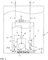
- FIG. 4 shows in an enlarged section of the fuel tank 3, a third embodiment of the in FIG. 1 shown fuel supply device 1.
- a suction jet pump 18 is arranged in the swirl pot 10 of the fuel tank 3.
- the suction jet pump, 18 is connected via the feed line 19 and arranged in the flow line 8 control valve 29 to the flow 5.
- the size of the drive current is adjusted and thus affects the performance of the ejector 18.
- the suction jet pump 18 is horizontally aligned in the swirl pot 10.
- the conveying direction of the suction jet pump 18 is oriented parallel to the bottom 24 of the swirl pot 10.
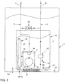
- FIG. 5 shows in an enlarged section of the fuel tank 3, a fourth embodiment of the in FIG. 1 shown fuel supply device 1.
- the suction jet pump 18 vertically aligned in the swirl pot 10.
- the conveying direction of the suction jet pump 18 is oriented perpendicular to the bottom 24 of the swirl pot 10.
- the control valve 29 is disposed in a housing 30 of the fuel pump 7.
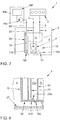
- FIG. 7 shows a fuel supply device 1 for supplying an internal combustion engine 2 and a heater 300, in particular a parking heater of a motor vehicle, with fuel from a fuel tank 3.
- the fuel supply device 1 comprises at least the fuel tank 3, which includes a tank volume 4, and a fuel tank 3 with the heater 300 connecting line 60, which includes a arranged in the fuel tank 3 intake 70.
- the fuel supply device 1 further comprises a collecting container 80, which is provided for receiving the intake line 70, wherein the collecting container 80 is arranged in a surge pot 10 of the fuel tank 3.
- a fuel pump 7 is arranged in the surge pot 10, which conveys fuel to the internal combustion engine 2 via a supply line 5.
- the swirl pot 10 includes a pot volume 11 a.
- the pot volume 11 is separated from the tank volume 4.
- the surge pot 10 has at least one inlet device 31.
- the feed device 31 is, for example, a check valve arranged in the boundary surface 150 of the swirl pot 10 and designed as a mushroom valve.
- the collecting container 80 has a valve device 160. This valve device 160 is designed as a check valve, preferably in the design of a mushroom valve. By means of the valve device 160, a collecting volume 170 of the collecting container 80 can be connected to the tank volume 4 of the fuel tank 3.
- the valve device 160 for connecting the collecting volume 170 with the tank volume 4 is arranged in the gravity field at the same height or higher than the inlet device 31 for connecting the pot volume 11 with the tank volume 4.
- the collecting volume 170 of the collecting container 80 is assigned exclusively to the heating device 300.
- the heater 300 has a pumping device 180.
- the heater 300 further includes a combustion apparatus 190 in which the fuel is burned.
- the collection container 80 has a in the FIG. 2 shown bottom 24 of the swirl pot 10 or on a bottom 27 of the fuel tank 3 side facing away from a particular permanent opening 230th
- FIG. 8 shows a sectional and enlarged view of a section of the in FIG. 1
- the fuel tank 80 is connected to the bottom 24 of the swirl pot 10, wherein the container bottom 210 of the collecting container 80 is executed at least partially konturbmony with the bottom 24 of the swirl pot 10.
- the valve device 160 is arranged in an opening of the container bottom 210.
- the bottom 24 or the container bottom 210 is at a distance from the base 27 of the fuel tank 3. This distance serves to ensure the inflow of fuel to the valve device 160.
- the suction line 70 arranged in the collecting container 80 has an inlet opening 230. This inlet opening 230 is assigned to the container floor 210, wherein the distance of the inlet opening 230 from the container floor 210 is smaller than five times the diameter of the suction line 70.
- the invention also relates to a fuel supply device 1, whose features in the description of the FIGS. 1 to 6 and the description of the FIGS. 7 and 8 are formed in combination.
- a fuel supply device 1 is formed for an internal combustion engine 2, the fuel tank 3 with a tank volume 4, and a flow 5 for guiding the fuel from the fuel tank 3 to the internal combustion engine 2, and the one Return line 6 for conducting unused fuel from the internal combustion engine 2 to the fuel tank 3, and the one fuel pump 7, which is arranged in the flow 5, and the inside of the fuel tank 3, a flow line 8 of the flow 5 and / or a return line 9 of the Return passage 6, and which comprises a arranged in the fuel tank 3 swirl pot 10 whose pot volume 11 is separated from the tank volume 4 of the fuel tank 3, wherein the swirl pot 10 is connected to the suction side of the fuel pump 7.
- the fuel supply device 1 for supplying the internal combustion engine 2 and the heating device 300 further comprises a suction jet pump 18 and / or a check valve 28 which are arranged in the fuel tank 3 and to fill the surge tank 10, the tank volume 4 with the pot volume 11 connect, wherein the suction jet pump 18th for supplying a drive current via a feed line 19 to the flow 5 and / or the return line 6 is connected, wherein the feed line 19 by means of a controllable function of the volume flow ratio between flow 5 and return 6 control valve 29 with the flow 5 and / or the return 6 is connected and / or the suction jet pump 18 is oriented with its conveying direction parallel to the vertical, in particular to the vertical vehicle axis.
Landscapes
- Engineering & Computer Science (AREA)
- Chemical & Material Sciences (AREA)
- Combustion & Propulsion (AREA)
- Mechanical Engineering (AREA)
- General Engineering & Computer Science (AREA)
- Cooling, Air Intake And Gas Exhaust, And Fuel Tank Arrangements In Propulsion Units (AREA)
Description
Die Erfindung betrifft eine Kraftstoffversorgungseinrichtung für eine Brennkraftmaschine, insbesondere eines Fahrzeugs, umfassend einen Kraftstofftank mit einem Tankvolumen, einen Vorlauf zur Leitung des Kraftstoffs aus dem Kraftstofftank zu der Brennkraftmaschine, einen Rücklauf zur Leitung von unverbrauchtem Kraftstoff von der Brennkraftmaschine zu dem Kraftstofftank, eine Kraftstoffpumpe, welche in dem Vorlauf angeordnet ist, im inneren des Kraftstofftanks eine Vorlaufleitung des Vorlaufs und/oder eine Rücklaufleitung des Rücklaufs sowie einen in dem Kraftstofftank angeordneten Schwalltopf, dessen Topfvolumen vom Tankvolumen des Kraftstofftanks getrennt ist, wobei der Schwalltopf mit der Saugseite der Kraftstoffpumpe verbunden ist.The invention relates to a fuel supply device for an internal combustion engine, in particular of a vehicle, comprising a fuel tank with a tank volume, a feed line for directing the fuel from the fuel tank to the internal combustion engine, a return line for the delivery of unused fuel from the internal combustion engine to the fuel tank, a fuel pump, which is arranged in the flow, inside the fuel tank, a flow line of the flow and / or a return line of the return and arranged in the fuel tank surge pot whose pot volume is separated from the tank volume of the fuel tank, wherein the surge chamber is connected to the suction side of the fuel pump.
Weiterhin betrifft die Erfindung eine Kraftstoffversorgungseinrichtung für eine Brennkraftmaschine, insbesondere eines Fahrzeugs, umfassend einen Kraftstofftank mit einem Tankvolumen, einen Vorlauf zur Leitung des Kraftstoffs aus dem Kraftstofftank zu der Brennkraftmaschine, einen Rücklauf zur Leitung von unverbrauchtem Kraftstoff von der Brennkraftmaschine zu dem Kraftstofftank, eine Kraftstoffpumpe, weiche in dem Vorlauf angeordnet ist, einen in dem Kraftstofftank angeordneten Schwalltopf, dessen Topfvolumen vom Tankvolumen des Kraftstofftanks getrennt ist und der mit der Saugseite der Kraftstoffpumpe verbunden ist, und eine Saugstrahlpumpe und/oder ein Rückschlagventil, weiche in dem Kraftstofftank angeordnet sind und zum Füllen des Schwalltopfs das Tankvolumen mit dem Topfvolumen verbinden, wobei die Saugstrahlpumpe zur Versorgung mit einem Treibstrom über eine Speisleitung mit dem Vorlauf, insbesondere mit der Vorlaufleitung, verbunden ist.Furthermore, the invention relates to a fuel supply device for an internal combustion engine, in particular of a vehicle, comprising a fuel tank with a tank volume, a lead for directing the fuel from the fuel tank to the internal combustion engine, a return line for conducting unused fuel from the internal combustion engine to the fuel tank, a fuel pump , which is arranged in the flow, arranged in the fuel tank baffle whose pot volume is separated from the tank volume of the fuel tank and which is connected to the suction side of the fuel pump, and a suction jet pump and / or a check valve, which are arranged in the fuel tank and the Fill the swirl pot to connect the tank volume with the pot volume, the suction jet pump is connected to supply a driving current via a feed line to the flow, in particular with the flow line.
Eine Kraftstoffversorgungseinrichtung mit einem Vorlauf, einem Rücklauf, einem Schwalltopf und einer Saugstrahlpumpe zum Füllen des Schwalltopfs ist aus der Druckschrift
Auch die Druckschriften
Kraftstoffversorgungseinrichtungen mit einem im Vorlauf angeordneten Druckbegrenzungsventil sind aus den Druckschriften
In der Druckschrift
Außerdem ist die Druckschrift
Eine Kraftstoffversorgungseinrichtung, bei der kein Schwalltopf, jedoch ein dem Pumpeneinlass zugeordneter Kraftstoffspeicher vorgesehen ist, ist in der Druckschrift
Bei den bekannten Kraftstoffversorgungseinrichtungen ist die Entnahmeleitung zweckmäßigerweise am Boden des Kraftstofftanks angeordnet, was eine nahezu restlose Entleerung des Kraftstofftanks ermöglicht. Bei einem nahezu geleerten Kraftstofftank tritt das Problem auf, dass bedingt durch Kurvenfahrten des Fahrzeugs und Straßenunebenheiten die Mündungsöffnung der Entnahmeleitung zumindest kurzzeitig nicht mehr von Kraftstoff umgeben ist. Die Folge ist, dass in einem solchen Fall Luft bzw. ein Luft-Kraftstoffdampf-Gemisch angesaugt wird. Um dies zu verhindern, ist es bekannt, am Boden des Kraftstofftanks einen auch Stautopf genannten Schwalltopf anzuordnen und dafür zu sorgen, dass in diesem stets ein gewisses Speichervolumen vorhanden ist. Einige wenige Liter Kraftstoff sind dabei schon ausreichend. Entscheidend ist dabei die Füllhöhe des Kraftstoffs. Bei einer Kurvenfahrt oder bei Unebenheiten des Straßenbelags kann die Kraftstoffflüssigkeit nicht seitlich aus dem Schwalltopf abfließen, so dass die am Boden des Staukopfs mündende Entnahmeleitung niemals frei liegt und entsprechend auch keine Luft angesaugt werden kann. Das Topfvolumen des Schwalltopfs wird durch eine Pumpe aufrechterhalten. In der Regel handelt es sich um eine Saugstrahlpumpe, also um eine nach dem Venturi-Prinzip arbeitende Pumpe. Angetrieben werden solche Pumpen in der Regel durch den Vorlaufstrom oder den Rücklaufstrom des Kraftstoffs.In the known fuel supply devices, the extraction line is expediently arranged at the bottom of the fuel tank, which allows a nearly complete emptying of the fuel tank. In a nearly empty fuel tank the problem arises that due to cornering of the vehicle and bumps the mouth of the extraction line is at least temporarily not surrounded by fuel. The result is that in such a case, air or an air-fuel vapor mixture is sucked. To prevent this, it is known to arrange at the bottom of the fuel tank and a baffle pot also called jam pot and to ensure that there is always a certain storage volume in this. A few liters of fuel are enough. The decisive factor is the filling level of the fuel. When cornering or when uneven the road surface, the fuel liquid can not flow off the side of the swirl pot, so that the opening at the bottom of the jam discharge line is never exposed and accordingly also no air can be sucked. The pot volume of the swirl pot is maintained by a pump. As a rule, it is an ejector pump, ie a pump operating on the Venturi principle. Such pumps are usually driven by the flow or the return flow of the fuel.
Üblicherweise ist in dem Vorlauf zwischen dem Kraftstofftank und der Brennkraftmaschine ein Kraftstofffilter vorgesehen. Der Kraftstofffilter befreit den Kraftstoff von Feststoffpartikeln. Unfiltrierter Kraftstoff kann verschiedene Arten von Verunreinigungen enthalten, beispielsweise Lackstücke oder Schmutz, die beim Befüllen in den Tank gelangt sind, aber auch Rost, welcher sich durch Feuchtigkeit in den Stahltanks gebildet hat, oder im kalten Kraftstoff auskristallisierte Paraffine. Werden diese Substanzen nicht entfernt, bevor der Kraftstoff in den Motor gelangt, sind ein vorzeitiger Verschleiß und Defekte in der Kraftstoffpumpe und dem Einspritzsystem wahrscheinüch - hervorgerufen sowohl durch Verstopfung von Düsen als auch durch eine den Verschleiß fördernde Wirkung der Partikel.Usually, a fuel filter is provided in the flow between the fuel tank and the internal combustion engine. The fuel filter frees the fuel from solid particles. Unfiltered fuel may contain various types of contaminants, such as pieces of paint or debris that have entered the tank when filled, as well as rust formed by moisture in the steel tanks or paraffins crystallized in the cold fuel. If these substances are not removed before the fuel enters the engine, premature wear and defects in the fuel pump and injection system are likely to be caused by both blockage of nozzles and wear-promoting action of the particles.
Da die Paraffinpartikel den Kraftstofffilter zusetzen können, sich jedoch bei einer Erwärmung über 288 Grad Kelvin wieder auflösen, wird der in der Brennkraftmaschine erwärmte Kraftstoff in den Kraftstofftank und/oder den Kraftstofffilter zurückgeführt. Jedoch ist es bei besonders niedrigen Umgebungstemperaturen, insbesondere unter 268 Grad Kelvin, und bei bestimmten Kraftstoffen, beispielsweise Diesel, erforderlich, schon vor und/oder bei einem Kaltstart den Kraftstoff zu erwärmen.Since the paraffin particles can clog the fuel filter, but re-dissolve when heated above 288 degrees Kelvin, the fuel heated in the internal combustion engine is returned to the fuel tank and / or the fuel filter. However, at particularly low ambient temperatures, in particular below 268 degrees Kelvin, and for certain fuels, for example diesel, it is necessary to heat the fuel before and / or during a cold start.
Schließlich ist noch die Druckschrift
Vor diesem Hintergrund liegt der Erfindung die Aufgabe zugrunde, eine optimierte Kraftstoffversorgungseinrichtung auszubilden.Against this background, the invention has the object of providing an optimized fuel supply device.
Insbesondere soll erreicht werden, dass ein Erwärmen des Kraftstoffs für den Kaltstart und/oder den Regelbetrieb, insbesondere bei geringen Umgebungstemperaturen, nicht erforderlich ist, wobei die Kraftstoffversorgungseinrichtung auch für Fahrzeuge einsetzbar sein soll, die eine Heizeinrichtung aufweisen.In particular, it is to be achieved that heating of the fuel for cold start and / or normal operation, in particular at low ambient temperatures, is not required, wherein the fuel supply device should also be usable for vehicles which have a heating device.
Die jeweiligen Unteransprüche betreffen besonders zweckmäßige Weiterbildungen der Erfindung.The respective subclaims relate to particularly expedient developments of the invention.
Die Aufgabe wird mit einer Kraftstoffversorgungseinrichtung gemäß den Merkmalen der Patentansprüche 1 oder 11 gelöst.The object is achieved with a fuel supply device according to the features of
Die Aufgabe wird ferner durch die Kombination der Patentansprüche 1 und 11 beziehungsweise der zugehörigen abhängigen Patentansprüche gelöst.The object is further achieved by the combination of
Ausgangspunkt der Erfindung ist eine Kraftstoffversorgungseinrichtung für eine Brennkraftmaschine, umfassend einen Kraftstofftank mit einem Tankvolumen, einen Vorlauf zur Leitung des Kraftstoffs aus dem Kraftstofftank zu der Brennkraftmaschine, einen Rücklauf zur Leitung von unverbrauchtem Kraftstoff von der Brennkraftmaschine zu dem Kraftstofftank, eine Kraftstoffpumpe, welche in dem Vorlauf angeordnet ist, im Inneren des Kraftstofftanks eine Vorlaufleitung des Vorlaufs und/oder eine Rücklaufleitung des Rücklaufs, einen in dem Kraftstofftank angeordneten Schwalltopf, dessen Topfvolumen vom Tankvolumen des Kraftstofftanks getrennt ist, wobei der Schwalltopf mit der Saugseite der Kraftstoffpumpe verbunden ist, wobei eine Saugstrahlpumpe im Schwalltopf angeordnet ist, der ein Rückschlagventil zur Verbindung des Schwalltopfs mit dem Topfvolumen umfasst.The starting point of the invention is a fuel supply device for an internal combustion engine, comprising a fuel tank with a tank volume, a feed line for the fuel from the fuel tank to the internal combustion engine, a return line for the delivery of unused fuel from the internal combustion engine to the fuel tank, a fuel pump, which in the Forward flow is arranged inside the fuel tank, a supply line of the flow and / or return line of the return, a pot arranged in the fuel tank, whose pot volume is separated from the tank volume of the fuel tank, wherein the surge chamber is connected to the suction side of the fuel pump, wherein a suction jet pump is arranged in the swirl pot, which includes a check valve for connecting the swirl pot with the pot volume.
Zur Lösung der Aufgabe ist es erfindungsgemäß vorgesehen, dass der Rücklauf zur Leitung von unverbrauchtem Kraftstoff von der Brennkraftmaschine zu dem Kraftstofftank der Saugseite der Kraftstoffpumpe zugeordnet ist und die Saugstrahlpumpe zur Versorgung mit einem Treibstrom über eine Speisleitung mit dem Vorlauf und/oder dem Rücklauf verbunden ist, wobei die Speisleitung mittels eines in Abhängigkeit des Volumenstromverhältnisses zwischen Vorlauf und Rücklauf steuerbaren Regelventils mit dem Vorlauf und/oder dem Rücklauf verbunden ist.To achieve the object, it is inventively provided that the return is associated with the line of unused fuel from the engine to the fuel tank of the suction side of the fuel pump and the suction jet pump is connected to supply a driving current via a feed line to the flow and / or the return , wherein the feed line is connected by means of a controllable depending on the volume flow ratio between flow and return control valve with the flow and / or the return.
Die Erfindung besteht somit insbesondere darin, dass die Speisleitung der Saugstrahlpumpe mittels eines in Abhängigkeit des Volumenstromverhältnisses zwischen Vorlauf und Rücklauf steuerbaren Regelventils mit dem Vorlauf verbunden ist und/oder die Saugstrahlpumpe mit ihrer Förderrichtung parallel zur Vertikalen, insbesondere zu der vertikalen Fahrzeugachse, orientiert ist. Als Treibstrom für die Saugstrahlpumpe wird Kraftstoff druckseitig der Kraftstoffpumpe aus dem Vorlauf entnommen. Bei einer Kraftstoffversorgungseinrichtung mit einer Rückführung kann der Anteil von Paraffinen und Partikeln im Vorlauf geringer sein als in dem Tankvolumen oder im Topfvolumen. Gerade bei einem Kaltstart sollte der Anteil von Paraffinen und Partikeln im Vorlauf möglichst gering sein. Die Verwendung des Kraftstoffs aus dem Vorlauf und/oder dem Rücklauf führt dazu, dass der verwendete Treibstrom durch ungefilterten Kraftstoff ersetzt wird und sich der Anteil von Paraffinen und Partikeln im Vorlauf erhöht. Durch die gezielte Ansteuerung der Saugstrahlpumpe in Abhängigkeit des Volumenstromverhältnisses zwischen Vorlauf und Rücklauf ist es möglich, bei einer hohen Rückführrate zumindest zeitweilig die Förderleistung der Saugstrahlpumpe zu mindern oder die Saugstrahlpumpe abzuschalten.The invention thus consists, in particular, in that the feed line of the suction jet pump is connected to the supply by means of a control valve controllable in dependence on the volume flow ratio between supply and return and / or the suction jet pump is oriented with its conveying direction parallel to the vertical, in particular to the vertical vehicle axis. As a drive current for the suction jet pump fuel pressure side of the fuel pump is removed from the flow. In a fuel supply device with a return, the proportion of paraffins and particles in the flow can be lower than in the tank volume or in the pot volume. Especially with a cold start, the proportion of paraffins and particles should be as low as possible in the flow. The use of the fuel from the supply and / or the return means that the used propellant flow is replaced by unfiltered fuel and increases the proportion of paraffins and particles in the flow. The targeted control of the suction jet pump as a function of the volume flow ratio between flow and return, it is possible at least temporarily to reduce the delivery capacity of the suction jet pump or shut off the suction jet pump at a high return rate.
Die Saugstrahlpumpe ist in der bereits genannten Ausgestaltung mit ihrer Förderrichtung parallel zur Vertikalen, insbesondere zu der vertikalen Fahrzeugachse orientiert. (
In einer anderen Ausgestaltung ist die Saugstrahlpumpe horizontal ausgerichtet ist, wodurch die Förderrichtung der Saugstrahlpumpe parallel zum Boden des Schwalltopfs orientiert ist. (
Durch die vertikale Anordnung der Saugstrahlpumpe, insbesondere durch die vertikale Anordnung von Mischrohr und Diffusor ist es möglich, eine radialsymmetrische Förderung zu erreichen. Da die Ansaugung und Förderung bei einer vertikal orientierten Saugstrahlpumpe vom Schwerefeld unbeeinflusst ist, erfolgt die Durchströmung des Mischrohrs und vor allem des Diffusors gleichmäßig und frei von einseitigen Verwirbelungen. In dem Kraftstofftank, insbesondere innerhalb des Schwalltopfs, ist der horizontale Bauraum begrenzt. Daher ermöglicht es die vertikale Orientierung der Saugstrahlpumpe, im Gegensatz zu den im Stand der Technik bekannten horizontal angeordneten Saugstrahlpumpen, das Mischrohr und vor allem den Diffusor nahezu beliebig lang zu gestalten. Die Länge der Saugstrahlpumpe und die Vermeidung von Verwirbelungen in der Saugstrahlpumpe verbessern deren Wirkungsgrad. Eine Saugstrahlpumpe mit besserem Wirkungsgrad benötigt zur Förderung eines bestimmten Auffüllvolumens weniger Treibstrom. Die Reduktion des Treibvolumenbedarfs reduziert insbesondere bei geringen Umgebungstemperaturen zugleich den Anteil von Paraffinen und Partikeln im Vorlauf.The vertical arrangement of the suction jet pump, in particular by the vertical arrangement of mixing tube and diffuser, it is possible to achieve a radially symmetric promotion. Since the intake and delivery of a vertically oriented suction jet pump from the gravity field is unaffected, the flow through the mixing tube and especially the diffuser is uniform and free of one-sided turbulence. In the fuel tank, in particular within the swirl pot, the horizontal space is limited. Therefore, in contrast to the horizontally arranged suction jet pumps known from the prior art, the vertical orientation of the suction jet pump makes it possible to design the mixing tube and above all the diffuser almost as long as desired. The length of the suction jet pump and the avoidance of turbulence in the suction jet pump improve their efficiency. A suction jet pump with better efficiency requires less drive current to convey a given fill volume. The reduction of the driving volume requirement also reduces the proportion of paraffins and particles in the forerun, especially at low ambient temperatures.
Es hat sich als günstig erwiesen, dass die Saugstrahlpumpe in dem Schwalltopf, insbesondere am Boden des Schwalltopfs, angeordnet ist. Hierdurch ist es möglich, die Saugstrahlpumpe mit dem Schwalltopf als eine Baugruppe auszuführen, was die Anzahl der zu montierenden Teile verringert. Weiterhin kann so die gesamte Höhe des Schwalltopfs für die Ausbildung der Saugstrahlpumpe genutzt werden. Darüber hinaus ist es möglich, die Saugstrahlpumpe direkt über einem in dem Boden des Schwalltopfs positionierten und den Schwalltopf mit dem Tankvolumen verbindenden Rückschlagventil anzuordnen. Gemäß einer weiterbildenden Ausführungsform ist das Rückschlagventil in der Saugstrahlpumpe, angeordnet. Das Rückschlagventil ist als ein eine Durchbrechung im Boden des Schwalltopfs verschließendes Pilzventil ausgeführt.It has proved to be favorable that the suction jet pump is arranged in the surge pot, in particular at the bottom of the surge pot. This makes it possible to perform the ejector with the surge pot as an assembly, which reduces the number of parts to be assembled. Furthermore, so the entire height of the swirl pot can be used for the formation of the suction jet pump. Moreover, it is possible to arrange the suction jet pump directly above a check valve positioned in the bottom of the swirl pot and connecting the swirl pot to the tank volume. According to a further embodiment, the check valve in the suction jet pump is arranged. The check valve is designed as a an opening in the bottom of the swirl pot occlusive mushroom valve.
Für eine Befüllung des Schwalltopfs bei abgeschalteter Kraftstoffpumpe und/oder abgeschalteter Saugstrahlpumpe ist in dem Schwalltopf ein weiteres Versorgungsventil vorgesehen. Das Versorgungsventil kann beispielsweise als Magnetventil ausgeführt sein, weiches bei eingeschaltetem Elektromotor der Kraftstoffpumpe schließt. Vorzugsweise ist das Versorgungsventil ein einfaches mechanisches Pilzventil.For a filling of the swirl pot when the fuel pump and / or switched off suction jet pump another supply valve is provided in the swirl pot. The supply valve may for example be designed as a solenoid valve, which closes when the electric motor of the fuel pump. Preferably, the supply valve is a simple mechanical mushroom valve.
Ferner besteht die Erfindung zur Lösung der Aufgabe darin, dass eine Kraftstoffversorgungseinrichtung vorgesehen ist, bei welcher der Rücklauf der Saugseite der Kraftstoffpumpe zugeordnet ist.Furthermore, the invention for achieving the object is that a fuel supply device is provided, in which the return of the suction side of the fuel pump is associated.
Da der von der Brennkraftmaschine zurückgeführte Kraftstoff bereits den Kraftstofffilter passiert hat und somit auch bei geringer Kraftstofftemperatur keine Paraffinpartikel mehr enthält, ist es durch die erfindungsgemäße Anordnung des Rücklaufs möglich, auf eine Heizeinrichtung zur Erwärmung des Kraftstoffs zu verzichten. Der umgewälzte und von Partikeln und Paraffinen befreite Kraftstoff stellt keine weitere Last für den Kraftstofffilter dar. Das gegenüber dem Umwälzvolumen verhältnismäßig geringe Verbrauchsvolumen wird zwar durch einen ungefilterfen Kraftstoff ersetzt, dessen Partikelfracht ist jedoch gering. Die Kraftstoffpumpe ist beispielsweise eine Kreiselpumpe und vorzugsweise angetrieben von einem Elektromotor. Die Kraftstoffpumpe fördert ungefähr 60 Liter Kraftstoff pro Stunde, während die Brennkraftmaschine im selben Zeitraum zirka 5 Liter Kraftstoff verbraucht.Since the fuel returned by the internal combustion engine has already passed through the fuel filter and thus no paraffin particles even at low fuel temperature, it is possible by the inventive arrangement of the return, to dispense with a heater for heating the fuel. The recirculated and freed from particles and paraffins fuel is no further burden for the fuel filter. Although the relatively small consumption volume compared to the circulation volume is replaced by an unfiltered fuel, whose particle load is low. The fuel pump is for example a centrifugal pump and preferably driven by an electric motor. The fuel pump delivers about 60 liters of fuel per hour while the engine consumes about 5 liters of fuel over the same period.
Als besonders günstige Ausgestaltung der Anordnung des Rücklaufs hat es sich erwiesen, dass der Rücklauf, insbesondere die Rücklaufleitung, nahe am Einlass der Kraftstoffpumpe in den Schwalltopf mündet und/oder mit der Saugseite der Kraftstoffpumpe verbunden ist. Es besteht somit, wenn der Rücklauf mit der Saugseite der Kraftstoffpumpe verbunden ist, keine offene Verbindung zwischen Rücklauf und Schwalltopf, wie es beispielsweise bei der in der Druckschrift
Zur Optimierung des Wirkungsgrads der Kraftstoffpumpe hat es sich als günstig erwiesen, dass die Saugleitung möglichst kurz ist. Dies wird erreicht, indem die Kraftstoffpumpe in dem Kraftstofftank, vorzugsweise in dem Schwalltopf angeordnet ist.To optimize the efficiency of the fuel pump, it has proven to be favorable that the suction line is as short as possible. This is achieved by arranging the fuel pump in the fuel tank, preferably in the swirl pot.
Die Kraftstoffversorgungseinrichtung umfasst auch ein Druckbegrenzungsventil zur Regelung des Drucks in dem Vorlauf. Hierbei ist es vorteilhaft, dass das Druckbegrenzungsventil einerseits mit dem Vorlauf und andererseits mit dem Rücklauf, insbesondere mit der Rücklaufleitung, verbunden ist. Überschreitet der Druck im Vorlauf einen Grenzwert, so ist für die Betriebssicherheit eine Druckminderung im Vorlauf erforderlich. Dieser Druckabbau erfolgt üblicherweise durch ein Druckbegrenzungsventil, welches den Vorlauf zum Tankvolumen und/oder zum Topfvolumen hin öffnet. Der Vorlauf enthält durch die Anbindung der Rückführung an die Saugseite der Kraftstoffpumpe einen sehr hohen Anteil gefilterten Kraftstoffs. Durch die Anbindung des Druckbegrenzungsventils einerseits an den Vorlauf und andererseits an den Rücklauf ist es möglich, einen Verlust des gefilterten Kraftstoffs zu minimieren. Eine Weiterbildung der Kraftstoffversorgungseinrichtung umfasst einen in dem Rücklauf stromabwärts nach dem Druckbegrenzungsventil angeordneten Pufferspeicher. Dieser dient dazu, den Kraftstoff aus dem öffnenden Druckbegrenzungsventil bei gefülltem Rücklauf aufzunehmen.The fuel supply device also includes a pressure relief valve for controlling the pressure in the flow. It is advantageous that the pressure relief valve is connected on the one hand with the flow and on the other hand with the return, in particular with the return line. If the pressure in the flow exceeds a limit value, a pressure reduction in the flow is required for operational safety. This pressure reduction is usually carried out by a pressure relief valve, which opens the flow to the tank volume and / or the pot volume. The flow contains a very high proportion of filtered fuel through the connection of the return to the suction side of the fuel pump. By connecting the pressure limiting valve on the one hand to the flow and on the other hand to the return, it is possible to minimize a loss of the filtered fuel. A further development of the fuel supply device comprises a buffer store arranged downstream of the pressure relief valve in the return line. This serves to receive the fuel from the opening pressure relief valve with a full return.
Gemäß einer anderen vorteilhaften Weiterbildung umfasst die Kraftstoffversorgungseinrichtung ein Temperaturbegrenzungsventil. Dieses Temperaturbegrenzungsventil dient dazu, insbesondere bei hoher Wärmeabgabe der Brennkraftmaschine und/oder bei hoher Umgebungstemperatur die Kraftstofftemperatur insbesondere im Vorlauf zu begrenzen. Dazu ist vorgesehen, dass das Temperaturbegrenzungsventil in dem Rücklauf, insbesondere in der Rücklaufleitung, angeordnet ist. Im Bereich des Kraftstofftanks ist die Kraftstofftemperatur im Rücklauf erfahrungsgemäß höher als im Vorlauf. So ist es möglich, rechtzeitig ein Überschreiten des Grenzwerts zu detektieren und die Kraftstofftemperatur entsprechend zu beeinflussen. Das Temperaturbegrenzungsventil ist vorzugsweise als ein mechanisches und/oder hydraulisches und/oder elektrisches, selbstregelndes und/oder ansteuerbares Dreiwegeventil ausgeführt. Vorzugsweise erfolgt die Steuerung des Temperaturbegrenzungsventils mittels eines Bimetalls, auch Knackfrosch genannt, oder mittels eines Wachsdehnelements. Dabei ist sowohl ein teilweises als auch ein vollständiges Unterbrechen der Anbindung des Rücklaufs an die Saugseite der Kraftstoffpumpe möglich.According to another advantageous development, the fuel supply device comprises a temperature limiting valve. This temperature limiting valve serves, in particular at high heat output of the internal combustion engine and / or at high ambient temperature, to limit the fuel temperature in particular in the flow. For this purpose, it is provided that the temperature limiting valve in the return, in particular in the return line, is arranged. In the area of the fuel tank, the temperature of the fuel in the return is, according to experience, higher than in the flow. It is thus possible to detect a timely exceeding of the limit value and to influence the fuel temperature accordingly. The temperature limiting valve is preferably designed as a mechanical and / or hydraulic and / or electrical, self-regulating and / or controllable three-way valve. Preferably, the control of the temperature limiting valve by means of a bimetal, also called crackling frog, or by means of a Wachsdehnelements. It is both a partial as also a complete interruption of the connection of the return to the suction side of the fuel pump possible.
Gemäß einer bevorzugten Ausführungsform verbindet das Temperaturbegrenzungsventil den Rücklauf, insbesondere die Rücklaufleitung, in Abhängigkeit der Temperatur des Kraftstoffs in dem Rücklauf mit dem Tankvolumen und/oder dem Topfvolumen und/oder der Saugseite der Kraftstoffpumpe. Überschreitet die Kraftstofftemperatur an dem Temperaturbegrenzungsventil einen Grenzwert, beispielsweise 303 Grad Kelvin, dann wird zumindest ein Teilstrom des von der Brennkraftmaschine zurückgeführten Kraftstoffs frei in den Schwalltopf abgegeben. Hier durchmischt sich der warme Kraftstoff aus der Rückführung mit dem ungefilterten Kraftstoff und kühlt ab. Da diese Regelung nur bei hohen Temperaturen erfolgt, bei denen der ungefilterte Kraftstoff wenige oder keine Paraffinpartikel enthält, kann der Anteil an gefiltertem Kraftstoff im Vorlauf geringer sein oder ganz wegfallen. Unterschreitet die Kraftstofftemperatur an dem Temperaturbegrenzungsventil einen Grenzwert, beispielsweise 288 Grad Kelvin, dann wird der von der Brennkraftmaschine zurückgeführte Kraftstoff wieder vollständig der Saugseite der Kraftstoffpumpe zugeführt. Das Temperaturbegrenzungsventil ist bevorzugt im Rücklauf in Strömungsrichtung des Kraftstoffs hinter dem Druckbegrenzungsventil angeordnet.According to a preferred embodiment, the temperature limiting valve connects the return line, in particular the return line, as a function of the temperature of the fuel in the return to the tank volume and / or the pot volume and / or the suction side of the fuel pump. If the fuel temperature at the temperature limiting valve exceeds a limit value, for example 303 degrees Kelvin, then at least a partial flow of the fuel returned by the internal combustion engine is released freely into the swirl pot. Here, the warm fuel from the recirculation mixes with the unfiltered fuel and cools down. Since this control is only at high temperatures, where the unfiltered fuel contains little or no paraffin particles, the proportion of filtered fuel in the flow can be lower or completely eliminated. If the fuel temperature at the temperature limiting valve falls below a limiting value, for example 288 degrees Kelvin, then the fuel recirculated by the internal combustion engine is again completely supplied to the suction side of the fuel pump. The temperature limiting valve is preferably arranged in the return flow in the flow direction of the fuel behind the pressure relief valve.
Eine Erhöhung der Kraftstofftemperatur im Vorlauf ist auch möglich, indem die Kraftstoffpumpe gezielt in einen energetisch ungünstigen Zustand versetzt wird. Beispielsweise wird dazu eine elektrische Kreiselpumpe drehzahlgesteuert mit maximaler Bestromung der Statorspulen betrieben. Dies ist beim Einsatz eines elektronisch kommutierten Motors (EC-Motor) möglich, da bei einem derartigen Motor die Drehzahl und das Drehmoment unabhängig voneinander geregelt werden können. Die überschüssige elektrische Leistung wird direkt in den Spulen in Wärme umgesetzt und zum Beispiel in dem Pumpenraum von dem Kraftstoff aufgenommen.An increase in the fuel temperature in the flow is also possible by the fuel pump is specifically placed in an energetically unfavorable state. For example, an electric centrifugal pump is operated speed-controlled with maximum energization of the stator coils. This is possible when using an electronically commutated motor (EC motor), since in such an engine, the speed and the torque can be controlled independently. The excess electrical power is converted directly into heat in the coils and taken up in the pump room of the fuel, for example.
Die bisher dargestellte Kraftstoffversorgungseinrichtung versorgt eine Brennkraftmaschine. In vielen Fahrzeugen wird jedoch auch eine Heizeinrichtung, in der Art einer Standheizung installiert.The fuel supply device shown so far supplies an internal combustion engine. In many vehicles, however, a heater is installed in the manner of a heater.
Die Erfindung betrifft somit auch eine Kraftstoffversorgungseinrichtung zur Versorgung einer Brennkraftmaschine und eine Heizeinrichtung.The invention thus also relates to a fuel supply device for supplying an internal combustion engine and a heating device.
Die bekannten Lösungen von Kraftstoffversorgungseinrichtungen zeichnen sich durch einen Kraftstofftank aus, der ein Tankvolumen einschließt, eine den Kraftstofftank mit der Heizeinrichtung verbindende Leitung, die eine im Kraftstofftank angeordnete Ansaugleitung umfasst, und einen Sammelbehälter, welcher zur Aufnahme der Ansaugleitung vorgesehen ist, wobei der Sammelbehälter in dem Kraftstofftank und/oder in einem Schwalltopf des Kraftstofftanks angeordnet ist.The known solutions of fuel supply devices are characterized by a fuel tank that includes a tank volume, a conduit connecting the fuel tank to the heater and including an intake pipe disposed in the fuel tank, and a sump, which is provided for receiving the suction line, wherein the sump is disposed in the fuel tank and / or in a surge pot of the fuel tank.
Die Druckschrift
Auch die Druckschriften
Es ist weiterhin durch die
In der Vergangenheit wurde der Kraftstoff für die Heizeinrichtung der Verbrennungsbauart mit einem Rohr aus einem Kraftstofftank eines Kraftfahrzeugs entnommen. Hierbei ergibt sich jedoch der Nachteil, dass besonders bei niedrigem Füllstand des Kraftstoffs im Kraftstofftank der Kraftstoff von einem Ansaugrohr wegschwappen kann. Darüber hinaus besteht die Gefahr, dass im Kraftstoff enthaltene Blasen oder Schäume, die sich vorwiegend an der Kraftstoffoberfläche befinden, in das Ansaugrohr gesaugt werden. Für die Kraftstoffversorgung des Verbrennungsmotors des Kraftfahrzeugs wird der Kraftstoff aus dem Kraftstofftank mittels eines eingebauten Schwalltopfs entnommen. Diese Schwalltöpfe sind am Kraftstofftankboden angeordnet und werden beispielsweise durch Überlaufen des Kraftstoffs über die Oberkante des Schwalltopfs durch eine mit einem Ventil versehene Öffnung im Boden des Schwalltopfs und durch eine Saugstrahlpumpe befüllt. Der Schwalltopf bevorratet Kraftstoff auch dann, wenn der Kraftstoff im Tank hin und her schwappt. Dadurch wird gewährleistet, dass am Ansaugrohr für die Kraftstoffversorgung des Verbrennungsmotors bei allen Fahrsituationen Kraftstoff ansteht. Eine deutliche Verbesserung des Betriebs der Heizeinrichtung wurde dadurch erreicht, dass der Kraftstoff aus dem Schwalltopf entnommen wird, da hier der Kraftstoff weniger wegschwappt. Bei einem nahezu leeren Tank ist das Topfvolumen des Schwalltopfs ausreichend für einen kurzzeitigen Betrieb der Brennkraftmaschine bemessen. So ist es beispielsweise möglich, noch eine Tankstelle anzufahren. Bei einem Fahrzeug kann der Betrieb der Heizeinrichtung, insbesondere bei abgeschalteter Saugstrahlpumpe oder einem nahezu leeren Tank, zur völligen Entleerung des Schwalltopfs führen. Ein von einer Heizeinrichtung entleerter Schwalltopf kann dazu führen, dass für den Start der Brennkraftmaschine kein Kraftstoff mehr zur Verfügung steht oder die Brennkraftmaschine Luft ansaugt.In the past, the fuel for the combustion type heater has been taken out with a pipe from a fuel tank of a motor vehicle. However, this has the disadvantage that, especially with a low filling level of the fuel in the fuel tank, the fuel can slosh away from an intake pipe. In addition, there is a risk that bubbles or foams contained in the fuel, which are predominantly located on the fuel surface, are sucked into the intake manifold. For the fuel supply of the internal combustion engine of the motor vehicle, the fuel is removed from the fuel tank by means of a built-in swirl pot. These baffles are arranged on the fuel tank bottom and are filled, for example, by overflowing the fuel through the top of the baffle through a valved orifice in the bottom of the baffle and through a suction jet pump. The swirl pot stores fuel even if the fuel spills in the tank. This ensures that fuel is present at the intake pipe for the fuel supply of the internal combustion engine in all driving situations. A significant improvement in the operation of the heater was achieved in that the fuel is removed from the swirl pot, since the fuel spills away less. In a nearly empty tank, the pot volume of the swirl pot is sufficiently sized for a short-term operation of the internal combustion engine. So it is possible, for example, to go to another gas station. In a vehicle, the operation of the heater, especially when the ejector pump or a nearly empty tank, to complete Empty the baffle. A swirl pot emptied by a heater can lead to the fuel no longer being available for the start of the internal combustion engine, or the internal combustion engine sucking in air.
Es wird eine optimierte Kraftstoffversorgungseinrichtung geschaffen, die es ermöglicht, dass die Heizeinrichtung und die Brennkraftmaschine unabhängig voneinander mit Kraftstoff aus einem gemeinsamen Kraftstofftank versorgt werden können.An optimized fuel supply device is provided, which makes it possible for the heating device and the internal combustion engine to be supplied with fuel from a common fuel tank independently of one another.
Die Kraftstoffversorgungseinrichtung umfasst zur Versorgung der Brennkraftmaschine in einer bevorzugten Ausgestaltung eine Heizeinrichtung, insbesondere eine Standheizung eines Kraftfahrzeugs. Es ist eine den Kraftstofftank mit der Heizeinrichtung verbindende Leitung vorgesehen, die eine im Kraftstofftank angeordnete Ansaugleitung umfasst, und einen Sammelbehälter, welcher zur Aufnahme der Ansaugleitung vorgesehen ist, wobei der Sammelbehälter in dem Schwalltopf des Kraftstofftanks angeordnet ist.In a preferred embodiment, the fuel supply device comprises a heating device for supplying the internal combustion engine, in particular a parking heater of a motor vehicle. There is provided a conduit connecting the fuel tank to the heater and including an intake passage disposed in the fuel tank, and a sump provided for receiving the intake passage, the sump being disposed in the surge tank of the fuel tank.
Der Sammelbehälter weist ferner eine Ventileinrichtung auf, weiche zur Verbindung des Sammelvolumens des Sammelbehälters mit dem Tankvolumen des Kraftstofftanks eingerichtet ist. Hierdurch ist es möglich, den Sammelbehälter aus dem Tankvolumen aufzufüllen, ohne den Schwalltopf dabei zu entleeren. Dies wird insbesondere dadurch ermöglicht, dass der Sammelbehälter ausschließlich der Heizeinrichtung zugeordnet ist. Dabei schließt der Sammelbehälter ein Sammelvolumen ein, welches von dem Topfvolumen des Schwalltopfs und/oder von dem Tankvolumen des Kraftstofftanks getrennt ist. Die Ventileinrichtung ist bevorzugt als ein zum Sammeivolumen des Sammelbehälters öffnendes Überdruckventil, beispielsweise als ein Pilzventil ausgeführt. Bei einem Regelbetrieb der Brennkraftmaschine, bei dem die kontinuierliche Füllung des Schwalltopfs sichergestellt ist, kann der Sammelbehälter auch mit dem Topfvolumen verbunden sein. Hierzu ist die Ventileinrichtung zum Beispiel als ein Dreiwegeventil ausgeführt. Dabei ist der Schwalltopf in dem Kraftstofftank angeordnet und das Topfvolumen des Schwalltopfs ist vom Tankvolumen des Kraftstofftanks getrennt. Hierdurch ist es möglich, die Heizeinrichtung und die Brennkraftmaschine unabhängig voneinander mit Kraftstoff aus einem gemeinsamen Kraftstofftank zu versorgen.The collecting container also has a valve device, which is set up to connect the collecting volume of the collecting container to the tank volume of the fuel tank. This makes it possible to fill the sump from the tank volume without emptying the swirl pot thereby. This is made possible in particular by the fact that the collecting container is assigned exclusively to the heating device. In this case, the collecting container includes a collecting volume, which is separated from the pot volume of the swirl pot and / or from the tank volume of the fuel tank. The valve device is preferably designed as a pressure relief valve which opens to the collecting volume of the collecting container, for example as a mushroom valve. In a control operation of the internal combustion engine, in which the continuous filling of the surge chamber is ensured, the collecting container can also be connected to the pot volume. For this purpose, the valve device is designed, for example, as a three-way valve. In this case, the swirl pot is arranged in the fuel tank and the pot volume of the swirl pot is separated from the tank volume of the fuel tank. This makes it possible to independently supply the heating device and the internal combustion engine with fuel from a common fuel tank.
Eine vorteilhafte Ausführungsform ist es, dass der Sammelbehälter mit dem Boden des Schwalltopfs verbunden ist. Hierdurch ist es möglich, die Ventileinrichtung direkt in dem gemeinsamen Boden von Schwalltopf und Sammelbehälter anzuordnen. Für eine einfache Herstellung des Sammelbehälters und eine geringe Anzahl zu montierender Teile ist es verteilhaft, dass der Sammelbehälter mit dem Schwalltopf als eine Baugruppe hergestellt ist. Vorzugsweise ist der Sammelbehälter mit dem Schwalltopf einteilig urgeformt. Die unmittelbare Anbindung des Sammelbehälters an das Tankvolumen verkürzt die Zuleitung zum Sammelbehälter und somit die Anzahl und die Komplexität der zu verbauenden Teile. Darüber hinaus kann so das Volumen des Sammelbehälters maximiert werden. Dabei ist es günstig, dass der Behälterboden des Sammelbehälters zumindest abschnittsweise konturbündig mit dem Boden des Schwalltopfs ausgeführt ist. Um einen sicheren Betrieb der Heizungseinrichtung über einen Zeitraum von 90 Sekunden aufrechtzuerhalten, umfasst das Sammelvolumen wenigstens 0,03 Liter. Ein möglichst großes Sammelvolumen steht auch dadurch zur Verfügung, dass die Einlassöffnung der Ansaugleitung am Behälterboden des Sammelbehälters angeordnet ist. Diese Anordnung wird erst durch die erfindungsgemäße Trennung des Sammelvolumens von dem Topfvolumen und die Verbindung des Sammelvolumens mit dem Tankvolumen möglich.An advantageous embodiment is that the collecting container is connected to the bottom of the swirl pot. This makes it possible to arrange the valve device directly in the common bottom of swirl pot and reservoir. For a simple manufacture of the collecting container and a small number of parts to be assembled, it is dispensable that the collecting container with the swirl pot is produced as an assembly. Preferably the collecting container with the swirl pot is in one piece urgeformt. The direct connection of the collecting container to the tank volume shortens the supply line to the collecting container and thus the number and complexity of the parts to be installed. In addition, so the volume of the sump can be maximized. It is favorable that the container bottom of the collecting container is executed at least in sections konturbündig with the bottom of the swirl pot. To maintain safe operation of the heater over a period of 90 seconds, the collection volume is at least 0.03 liters. The largest possible collecting volume is also available in that the inlet opening of the suction line is arranged on the container bottom of the collecting container. This arrangement is possible only by the inventive separation of the collection volume of the pot volume and the connection of the collection volume with the tank volume.
Vorzugsweise weist der Sammelbehälters eine Öffnung auf, welche an einem von dem Boden des Schwalltopfs und/oder an einem von dem Grund des Kraftstofftanks entfernten Ende beziehungsweise an einer gegenüberliegenden Seite positioniert ist. Diese Öffnung liegt also im Schwerefeld an dem obersten Abschnitt des Sammelbehälters. Bei einem vollen Schwalltopf und/oder einem vollen Kraftstofftank besteht so die Möglichkeit, dass der Sammelbehälter durch ein Überlaufen des Kraftstoffs aus dem Tankvolumen und/oder Topfvolumen in das Sammelvolumen gefüllt wird. Hierzu ist die Öffnung mit dem Topfvolumen des Schwalltopfs und/oder dem Tankvolumen des Kraftstofftanks verbunden. Das Sammelvolumen wird aus dem Tankvolumen bei Stillstand der Brennkraftmaschine über die Ventileinrichtung und bei Betrieb der Brennkraftmaschine und/oder bei Betrieb der Schwallpumpe über das Topfvolumen befüllt.Preferably, the sump has an opening positioned at one end remote from the bottom of the baffle and / or at an end remote from the bottom of the fuel tank. This opening is therefore in the gravitational field at the top of the collection container. With a full swirl pot and / or a full fuel tank, there is the possibility that the collecting container is filled by an overflow of the fuel from the tank volume and / or pot volume in the collecting volume. For this purpose, the opening is connected to the pot volume of the swirl pot and / or the tank volume of the fuel tank. The collecting volume is filled from the tank volume at standstill of the internal combustion engine via the valve device and during operation of the internal combustion engine and / or during operation of the surge pump via the pot volume.
Eine günstige Ausführungsform ist es, dass der Sammelbehälter über mindestens zwei Drittel der Höhe des Schwalltopfs erstreckt ist. Dies ermöglicht einerseits, ein großes Sammelvolumen zu erhalten, andererseits bleibt so bei einem Ausbleiben der weiteren Auffüllung des Sammelbehälters und gleichzeitigem Betrieb der Heizeinrichtung genügend Kraftstoff in dem Sammelbehälter für einen erneuten Start der Brennkraftmaschine.A favorable embodiment is that the collecting container is extended over at least two thirds of the height of the swirl pot. On the one hand, this makes it possible to obtain a large collecting volume; on the other hand, if there is a lack of further filling of the collecting container and simultaneous operation of the heating device, sufficient fuel remains in the collecting container for a restart of the internal combustion engine.
Vorzugsweise ist die Verbindung des Topfvolumens mit dem Tankvolumen unabhängig von der Verbindung des Sammelvolumens mit dem Tankvolumen. Dabei ist es günstig, dass die zum Auffüllen des Topfvolumens vorgesehene Entnahmestelle in dem Tankvolumen im Schwerefeld weiter unten, also näher am Grund des Kraftstofftanks, angeordnet ist als die Verbindung des Sammelvolumens mit dem Tankvolumen.Preferably, the connection of the pot volume with the tank volume is independent of the connection of the collecting volume with the tank volume. It is favorable that the removal point provided for filling the pot volume in the tank volume in the gravitational field further down, that is closer to the bottom of the fuel tank, is arranged as the connection of the collecting volume with the tank volume.
Die Erfindung lässt zahlreiche Ausführungsformen zu. Zur weiteren Verdeutlichung ihres Grundprinzips sind einige davon in den Zeichnungen dargestellt und werden nachfolgend beschrieben. Die Zeichnungen zeigen in
- Fig. 1
- eine schematische Darstellung einer Kraftstoffversorgungseinrichtung;
- Fig. 2
- eine schematische Darstellung der in
Figur 1 - Fig. 3
- eine schematische Darstellung der in
Figur 1 - Fig. 4
- eine schematische Darstellung der in
Figur 1 - Fig. 5
- eine schematische Darstellung der in
Figur 1 - Fig. 6
- eine schematische Darstellung der in
Figur 5 - Fig. 7
- eine schematische Darstellung einer Kraftstoffversorgungseinrichtung;
- Fig. 8
- eine geschnittene, vergrößerte Darstellung eines Ausschnitts eines Kraftstofftanks.
- Fig. 1
- a schematic representation of a fuel supply device;
- Fig. 2
- a schematic representation of in
FIG. 1 shown fuel supply device in a first embodiment; - Fig. 3
- a schematic representation of in
FIG. 1 shown fuel supply device in a second embodiment; - Fig. 4
- a schematic representation of in
FIG. 1 shown fuel supply device in a third embodiment; - Fig. 5
- a schematic representation of in
FIG. 1 shown fuel supply device in a fourth embodiment; - Fig. 6
- a schematic representation of in
FIG. 5 shown suction jet pump; - Fig. 7
- a schematic representation of a fuel supply device;
- Fig. 8
- a sectioned, enlarged view of a section of a fuel tank.
Die
Die
Die Erfindung betrifft auch eine Kraftstoffversorgungseinrichtung 1, deren Merkmale in der Beschreibung zu den
Insbesondere aus den
Das heißt, es wird eine Kraftstoffversorgungseinrichtung 1 vorgeschlagen, die sowohl mindestens die technischen Merkmale des Patentanspruchs 1 und gegebenenfalls deren Unteransprüche 2 bis 15 umfasst.That is, it is proposed a
Durch Kombination der technischen Merkmale der Patentansprüche 1 und 11 wird eine Kraftstoffversorgungseinrichtung 1 für eine Brennkraftmaschine 2 ausgebildet, die einen Kraftstofftank 3 mit einem Tankvolumen 4, und die einen Vorlauf 5 zur Leitung des Kraftstoffs aus dem Kraftstofftank 3 zu der Brennkraftmaschine 2, und die einen Rücklauf 6 zur Leitung von unverbrauchtem Kraftstoff von der Brennkraftmaschine 2 zu dem Kraftstofftank 3, und die eine Kraftstoffpumpe 7, welche in dem Vorlauf 5 angeordnet ist, und die im Inneren des Kraftstofftanks 3 eine Vorlaufleitung 8 des Vorlaufs 5 und/oder eine Rücklaufleitung 9 des Rücklaufs 6, und die einen in dem Kraftstofftank 3 angeordneten Schwalltopf 10 umfasst, dessen Topfvolumen 11 vom Tankvolumen 4 des Kraftstofftanks 3 getrennt ist, wobei der Schwalltopf 10 mit der Saugseite der Kraftstoffpumpe 7 verbunden ist.By combining the technical features of
Ferner ist in Kombination mit den soeben genannten Merkmalen vorgesehen, dass die Kraftstoffversorgungseinrichtung 1 zur Versorgung der Brennkraftmaschine 2 und der Heizeinrichtung 300, insbesondere einer Standheizung eines Kraftfahrzeugs, eine den Kraftstofftank 3 mit der Heizeinrichtung 300 verbindende Leitung 60, die eine im Kraftstofftank 3 angeordnete Ansaugleitung 70 umfasst, und einen Sammelbehälter 80, welcher zur Aufnahme der Ansaugleitung 70 vorgesehen ist, wobei der Sammelbehälter 80 in dem Schwalltopf 10 des Kraftstofftanks 3 angeordnet ist, wobei der Sammelbehälter 80 eine Ventileinrichtung 160 aufweist, welche zur Verbindung eines Sammelvolumens 170 des Sammelbehälters 80 mit dem Tankvolumen 4 des Kraftstofftanks 3 eingerichtet ist.Furthermore, it is provided in combination with the just mentioned features that the
Die Kraftstoffversorgungseinrichtung 1 zur Versorgung der Brennkraftmaschine 2 und der Heizeinrichtung 300 umfasst ferner eine Saugstrahlpumpe 18 und/oder ein Rückschlagventil 28, welche in dem Kraftstofftank 3 angeordnet sind und zum Füllen des Schwalltopfs 10 das Tankvolumen 4 mit dem Topfvolumen 11 verbinden, wobei die Saugstrahlpumpe 18 zur Versorgung mit einem Treibstrom über eine Speisleitung 19 mit dem Vorlauf 5 und/oder dem Rücklauf 6 verbunden ist, wobei die Speisleitung 19 mittels eines in Abhängigkeit des Volumenstromverhältnisses zwischen Vorlauf 5 und Rücklauf 6 steuerbaren Regelventils 29 mit dem Vorlauf 5 und/oder dem Rücklauf 6 verbunden ist und/oder die Saugstrahlpumpe 18 mit ihrer Förderrichtung parallel zur Vertikalen, insbesondere zu der vertikalen Fahrzeugachse, orientiert ist.The
Die in den abhängigen Patentansprüchen 2 bis 15 gelehrten technischen Merkmale mit den erläuterten Vorteilen schließen sich entsprechend an die durch Kombination der Patentansprüche 1 und 11 dargestellte Lehre zum Aufbau einer Kraftstoffversorgungseinrichtung 1 für eine Brennkraftmaschine 2 mit einer Heizeinrichtung 300 an.The technical features taught in the
- 11
- KraftstoffversorgungseinrichtungFuel supply
- 22
- BrennkraftmaschineInternal combustion engine
- 33
- KraftstofftankFuel tank
- 44
- Tankvolumentank capacity
- 55
- Vorlaufleader
- 66
- Rücklaufreturns
- 77
- KraftstoffpumpeFuel pump
- 88th
- Vorlaufleitungsupply line
- 99
- RücklaufleitungReturn line
- 1010
- Schwalltopfswirl pot
- 1111
- Topfvolumenpot volume
- 1212
- Filtersiebfilter screen
- 1313
- KraftstofffilterFuel filter
- 1414
- Saugleitungsuction
- 1515
- DruckbegrenzungsventilPressure relief valve
- 1616
- TemperaturbegrenzungsventilTemperature relief valve
- 1717
- Auslassoutlet
- 1818
- Saugstrahlpumpeeductor
- 1919
- Speisleitungfeeding line
- 2020
- Düsejet
- 2121
- Mischrohrmixing tube
- 2222
- Diffusordiffuser
- 2323
- ZulaufIntake
- 2424
- Bodenground
- 2525
- Durchbrechungperforation
- 2626
- Abstanddistance
- 2727
- Grundreason
- 2828
- Rückschlagventilcheck valve
- 2929
- Regelventilcontrol valve
- 3030
- Gehäuse der KraftstoffpumpeHousing of the fuel pump
- 3131
- Zulaufeinrichtung/VersorgungsventilInlet device / supply valve
- 6060
- Leitungmanagement
- 7070
- Ansaugleitungsuction
- 8080
- SammelbehälterClippings
- 150150
- Begrenzungsflächeboundary surface
- 160160
- Ventileinrichtungvalve means
- 170170
- Sammelvolumencollection volume
- 180180
- Pumpeneinrichtungpump means
- 190190
- Verbrennungsapparatincinerator
- 210210
- Behälterbodencontainer bottom
- 230230
- Öffnung/EinlassöffnungOpening / inlet port
- 300300
- Heizeinrichtungheater
Claims (15)
- Fuel supply device (1) for an internal combustion engine (2), comprising a fuel tank (3) with a tank volume (4), a feed (5) for conducting the fuel out of the fuel tank (3) to the internal combustion engine (2), a return (6) for conducting unused fuel from the internal combustion engine (2) to the fuel tank (3), a fuel pump (7) which is arranged in the feed (5), a feed line (8) of the feed (5) and/or a return line (9) of the return (6) in the interior of the fuel tank (3), a splash pot (10) which is arranged in the fuel tank (3) and the pot volume (11) of which is separated from the tank volume (4) of the fuel tank (3), the splash pot (10) being connected to the suction side of the fuel pump (7), and a suction jet pump (18) being arranged in the splash pot (10) which comprises a check valve (28) for connecting the splash pot (10) to the pot volume (11), characterized in that the return (6) for conducting unused fuel from the internal combustion engine (2) to the fuel tank (3) is assigned to the suction side of the fuel pump (7), and the suction jet pump (18) is connected to the feed (5) and/or the return (6) via a feeder line (19) for the supply with a drive flow, the feeder line (19) being connected to the feed (5) and/or the return (6) by means of a regulating valve (29) which can be controlled in a manner which is dependent on the volumetric flow ratio between the feed (5) and the return (6).
- Fuel supply device (1) according to Claim 1, characterized in that the suction jet pump (18) is arranged in the splash pot (10), in particular on the bottom (24) of the splash pot (10).
- Fuel supply device (1) according to Claim 1 or 2, characterized in that the suction jet pump (18) is oriented with its delivery direction parallel to the vertical, in particular to the vertical vehicle axis, or is aligned horizontally, as a result of which the delivery direction of the suction jet pump (18) is oriented parallel to the bottom (24) of the splash pot (10).
- Fuel supply device (1) according to Claim 1, characterized in that the check valve (28) is arranged in the bottom (24) of the splash pot (10) and/or in the suction jet pump (18).
- Fuel supply device (1) according to Claim 1, characterized in that the return (6), in particular the return line (9), opens into the splash pot (10) close to the inlet of the fuel pump (7) and/or is connected to the suction side of the fuel pump (7).
- Fuel supply device (1) according to Claim 5, characterized in that the fuel pump (7) comprises a suction line (14) which is connected firstly to the pump space of the fuel pump (7) and secondly to a filter screen (12) which is arranged in the splash pot (10), the return (6), in particular the return line (9), being connected to the filter screen (12) of the fuel pump (7) and/or to the suction line (14) of the fuel pump (7).
- Fuel supply device (1) according to Claim 1, characterized in that the fuel supply device (1) comprises a pressure limiting valve (15) for regulating the pressure in the feed (5), which pressure limiting valve (15) is connected firstly to the feed (5) and secondly to the return (6), in particular to the feed line (8) and/or to the return line (9).
- Fuel supply device (1) according to Claim 1, characterized in that the fuel supply device (1) comprises a temperature limiting valve (16) which is arranged in the return (6), in particular in the return line (9).
- Fuel supply device (1) according to Claim 8, characterized in that the temperature limiting valve (16) connects the return (6), in particular the return line (9), to the tank volume (4) and/or the pot volume (11) and/or the suction side of the fuel pump (7) in a manner which is dependent on the temperature of the fuel in the return (6).
- Fuel supply device (1) according to Claim 8, characterized in that the temperature limiting valve (16) is arranged in the return (6) downstream of the pressure limiting valve (15) in the flow direction of the fuel.
- Fuel supply device (1) according to Claim 1, characterized by a heating device (300) and a line (60) which connects the fuel tank (3) to the heating device (300) and comprises an intake line (70) which is arranged in the fuel tank (3), and a collecting vessel (80) which is assigned exclusively to the heating device (300) and is arranged in the splash pot (10) of the fuel tank (3), the collecting volume (170) of which collecting vessel (80) is separated from the pot volume (11) of the splash pot (10) and/or from the tank volume (4) of the fuel tank (3), and which collecting vessel (80) is provided for receiving the intake line (70).
- Fuel supply device (1) according to Claim 11, characterized in that the collecting vessel (80) has a valve device (160) which is set up to connect the collecting volume (170) of the collecting vessel (80) to the tank volume (4) of the fuel tank (3), the valve device (160) for connecting the collecting volume (170) to the tank volume (4) being arranged in the field of gravity at the same height as or higher up than the feeding device (31) for connecting the pot volume (11) to the tank volume (4).
- Fuel supply device (1) according to Claim 11, characterized in that the collecting vessel (80) is connected to a bottom (24) of the splash pot (10), and a vessel bottom (210) of the collecting vessel (80) is configured at least in sections with a flush contour with respect to the bottom (24) of the splash pot (10).
- Fuel supply device (1) according to Claim 13, characterized in that the collecting vessel (80) has a permanent opening (23) on a side which faces away from the bottom (24) of the splash pot (10) and/or from a base (27) of the fuel tank (3), with the result that the collecting volume (170) of the collecting vessel (80) is connected via the opening (23) to the pot volume (11) of the splash pot (10) and/or the tank volume (4) of the fuel tank (3).
- Fuel supply device (1) according to Claim 11, characterized in that the collecting vessel (80) extends over at least two thirds of the height of the splash pot (10).
Applications Claiming Priority (3)
| Application Number | Priority Date | Filing Date | Title |
|---|---|---|---|
| DE201210020321 DE102012020321A1 (en) | 2012-10-13 | 2012-10-13 | Fuel supply device for supplying fuel to engine-independent heater, in internal combustion engine of vehicle i.e. motor car, has ejector pump oriented with delivery direction parallel to vertical vehicle axis |
| DE201210020396 DE102012020396A1 (en) | 2012-10-18 | 2012-10-18 | Fuel supply device for supplying fuel to engine-independent heater, in internal combustion engine of vehicle i.e. motor car, has ejector pump oriented with delivery direction parallel to vertical vehicle axis |
| PCT/EP2013/071296 WO2014057093A1 (en) | 2012-10-13 | 2013-10-11 | Fuel supply device |
Publications (2)
| Publication Number | Publication Date |
|---|---|
| EP2906813A1 EP2906813A1 (en) | 2015-08-19 |
| EP2906813B1 true EP2906813B1 (en) | 2018-04-18 |
Family
ID=49354661
Family Applications (1)
| Application Number | Title | Priority Date | Filing Date |
|---|---|---|---|
| EP13776477.5A Not-in-force EP2906813B1 (en) | 2012-10-13 | 2013-10-11 | Fuel supply device |
Country Status (3)
| Country | Link |
|---|---|
| EP (1) | EP2906813B1 (en) |
| CN (1) | CN104838128B (en) |
| WO (1) | WO2014057093A1 (en) |
Families Citing this family (6)
| Publication number | Priority date | Publication date | Assignee | Title |
|---|---|---|---|---|
| SE537848C2 (en) * | 2013-04-29 | 2015-11-03 | Scania Cv Ab | Combustion engine fuel system, internal combustion engine with such a fuel system, vehicles with such a fuel system and a method for regulating a fuel system |
| DE102014016190B4 (en) | 2014-11-03 | 2018-09-20 | Audi Ag | Method for operating a fuel tank device for a motor vehicle and corresponding fuel tank device |
| DE102016014881A1 (en) | 2016-12-14 | 2017-07-06 | Daimler Ag | The fuel tank system |
| CN112984368B (en) | 2019-12-16 | 2025-03-14 | 中集安瑞科工程科技有限公司 | A low-temperature full-containment tank that uses a pump column to realize the extraction function of low-liquid-level materials |
| FR3110195B1 (en) * | 2020-05-18 | 2022-08-19 | Safran Aerosystems | Aircraft comprising in its fuel tank a chamber equipped with a sensor |
| CN115139781A (en) * | 2021-03-30 | 2022-10-04 | 广州汽车集团股份有限公司 | Fuel tank and automobile |
Family Cites Families (16)
| Publication number | Priority date | Publication date | Assignee | Title |
|---|---|---|---|---|
| DE4426685B4 (en) | 1993-08-25 | 2004-03-11 | Volkswagen Ag | Fuel supply for an internal combustion engine with a fuel tank forming at least two sub-tanks |
| DE19541723C2 (en) | 1994-11-09 | 1999-02-18 | Alfmeier Walter Gmbh & Co | Tank withdrawal device |
| DE19625629A1 (en) | 1995-06-30 | 1997-01-02 | Walbro Corp | Module unit with fuel pump and accumulator container arranged in tank |
| DE19540892A1 (en) * | 1995-11-02 | 1997-05-07 | Bayerische Motoren Werke Ag | Fuel system |
| DE19547243A1 (en) | 1995-12-18 | 1997-06-19 | Bayerische Motoren Werke Ag | Fuel delivery system |
| DE19750036C2 (en) | 1997-11-12 | 1999-09-02 | Mannesmann Vdo Ag | Fuel delivery device |
| DE19961923A1 (en) * | 1999-12-22 | 2001-07-05 | Bosch Gmbh Robert | Fuel delivery module for vehicle has jet pump that pumps fuel from fuel tank to storage container next to feed assembly, connected to flow channel by channel on storage container floor |
| DE10303390A1 (en) * | 2003-01-29 | 2004-08-05 | Robert Bosch Gmbh | Arrangement for transporting fuel from tank to vehicle combustion engine, has suction jet pump mixing channel perpendicular to supply tank top at least approximately coaxially above non-return valve |
| DE102004061874B4 (en) * | 2003-12-22 | 2017-05-24 | Ti Automotive Fuel Systems Sas | Fuel pump module |
| DE102005000729A1 (en) | 2005-01-04 | 2006-07-13 | Siemens Ag | Suction device for a parking heater of a motor vehicle |
| DE102005059457B4 (en) | 2005-12-13 | 2021-02-18 | Volkswagen Ag | Parking heater and a dedicated intake manifold |
| DE102005061604B4 (en) | 2005-12-22 | 2013-09-19 | Webasto Ag | Fuel extraction system for an auxiliary heater, auxiliary heater and motor vehicle with such a fuel extraction system |
| DE102006017471B4 (en) | 2006-04-13 | 2021-05-20 | Vitesco Technologies GmbH | Suction unit for an auxiliary heater of a motor vehicle |
| DE102008001240A1 (en) * | 2007-11-13 | 2009-05-14 | Robert Bosch Gmbh | Method and device for controlling a fuel supply system |
| DE102008044904A1 (en) | 2008-08-29 | 2010-03-04 | Continental Automotive Gmbh | Fuel supply system for a motor vehicle |
| US20110041931A1 (en) | 2009-08-21 | 2011-02-24 | Gmglobal Technology Operations, Inc. | Diesel Fuel Pump Module with Fuel Wax By-Pass |
-
2013
- 2013-10-11 EP EP13776477.5A patent/EP2906813B1/en not_active Not-in-force
- 2013-10-11 CN CN201380053457.2A patent/CN104838128B/en active Active
- 2013-10-11 WO PCT/EP2013/071296 patent/WO2014057093A1/en not_active Ceased
Non-Patent Citations (1)
| Title |
|---|
| None * |
Also Published As
| Publication number | Publication date |
|---|---|
| WO2014057093A1 (en) | 2014-04-17 |
| CN104838128B (en) | 2017-09-12 |
| CN104838128A (en) | 2015-08-12 |
| EP2906813A1 (en) | 2015-08-19 |
Similar Documents
| Publication | Publication Date | Title |
|---|---|---|
| EP2906813A1 (en) | Fuel supply device | |
| DE102005027218B4 (en) | Fuel supply device for non-return fuel supply system | |
| DE102008060090A1 (en) | Fuel conveyor | |
| EP3990318B1 (en) | Motor vehicle comprising a water provision unit and method for operating a motor vehicle | |
| EP1254311B1 (en) | Fuel supply system for internal combustion engines allowing for an improved filling of the fuel line | |
| EP3014099B1 (en) | Fuel delivery system with partial pressure reduction valve in supply line of jet pump | |
| WO2012150059A1 (en) | Jet pump for delivering fuel | |
| DE102018110661B4 (en) | Concave discharge outlet for fuel cells | |
| DE102012020321A1 (en) | Fuel supply device for supplying fuel to engine-independent heater, in internal combustion engine of vehicle i.e. motor car, has ejector pump oriented with delivery direction parallel to vertical vehicle axis | |
| DE112014001070B4 (en) | Fuel system for an internal combustion engine, internal combustion engine and vehicle with such a fuel system and method for replacing a filter element in a fuel system | |
| DE112013004304B4 (en) | fuel supply system | |
| WO2003052262A1 (en) | Low-pressure circuit for a reservoir injection system | |
| DE112014001066B4 (en) | Fuel system for an internal combustion engine | |
| EP0608499B1 (en) | Liquid fuel tank system, esp. for combustion engines in motor vehicles | |
| DE102012004881A1 (en) | Method and apparatus for separating gas from a flowable medium | |
| DE112010001133T5 (en) | lubricator | |
| EP2397698A1 (en) | Conveying device | |
| EP1433949B1 (en) | Fuel supply system for the supply of fuel and ejector pump therefor | |
| DE102013222407A1 (en) | Fuel cleaning by demand control of a fuel delivery device | |
| DE102012020396A1 (en) | Fuel supply device for supplying fuel to engine-independent heater, in internal combustion engine of vehicle i.e. motor car, has ejector pump oriented with delivery direction parallel to vertical vehicle axis | |
| DE102016014881A1 (en) | The fuel tank system | |
| WO2018114128A1 (en) | Fuel delivery device | |
| EP2769076A1 (en) | Fuel delivery device with inclined suction jet pump | |
| DE102005059457B4 (en) | Parking heater and a dedicated intake manifold | |
| DE3323031A1 (en) | Ship |
Legal Events
| Date | Code | Title | Description |
|---|---|---|---|
| PUAI | Public reference made under article 153(3) epc to a published international application that has entered the european phase |
Free format text: ORIGINAL CODE: 0009012 |
|
| 17P | Request for examination filed |
Effective date: 20150506 |
|
| AK | Designated contracting states |
Kind code of ref document: A1 Designated state(s): AL AT BE BG CH CY CZ DE DK EE ES FI FR GB GR HR HU IE IS IT LI LT LU LV MC MK MT NL NO PL PT RO RS SE SI SK SM TR |
|
| AX | Request for extension of the european patent |
Extension state: BA ME |
|
| DAX | Request for extension of the european patent (deleted) | ||
| GRAP | Despatch of communication of intention to grant a patent |
Free format text: ORIGINAL CODE: EPIDOSNIGR1 |
|
| STAA | Information on the status of an ep patent application or granted ep patent |
Free format text: STATUS: GRANT OF PATENT IS INTENDED |
|
| INTG | Intention to grant announced |
Effective date: 20170727 |
|
| GRAJ | Information related to disapproval of communication of intention to grant by the applicant or resumption of examination proceedings by the epo deleted |
Free format text: ORIGINAL CODE: EPIDOSDIGR1 |
|
| STAA | Information on the status of an ep patent application or granted ep patent |
Free format text: STATUS: GRANT OF PATENT IS INTENDED |
|
| GRAJ | Information related to disapproval of communication of intention to grant by the applicant or resumption of examination proceedings by the epo deleted |
Free format text: ORIGINAL CODE: EPIDOSDIGR1 |
|
| STAA | Information on the status of an ep patent application or granted ep patent |
Free format text: STATUS: REQUEST FOR EXAMINATION WAS MADE |
|
| RIN1 | Information on inventor provided before grant (corrected) |
Inventor name: KRABUS, OLAF Inventor name: HELMS, INGO Inventor name: POTT, RONALD |
|
| GRAP | Despatch of communication of intention to grant a patent |
Free format text: ORIGINAL CODE: EPIDOSNIGR1 |
|
| STAA | Information on the status of an ep patent application or granted ep patent |
Free format text: STATUS: GRANT OF PATENT IS INTENDED |
|
| INTC | Intention to grant announced (deleted) | ||
| INTG | Intention to grant announced |
Effective date: 20170727 |
|
| INTC | Intention to grant announced (deleted) | ||
| INTG | Intention to grant announced |
Effective date: 20171219 |
|
| GRAJ | Information related to disapproval of communication of intention to grant by the applicant or resumption of examination proceedings by the epo deleted |
Free format text: ORIGINAL CODE: EPIDOSDIGR1 |
|
| STAA | Information on the status of an ep patent application or granted ep patent |
Free format text: STATUS: REQUEST FOR EXAMINATION WAS MADE |
|
| INTC | Intention to grant announced (deleted) | ||
| STAA | Information on the status of an ep patent application or granted ep patent |
Free format text: STATUS: GRANT OF PATENT IS INTENDED |
|
| GRAS | Grant fee paid |
Free format text: ORIGINAL CODE: EPIDOSNIGR3 |
|
| GRAA | (expected) grant |
Free format text: ORIGINAL CODE: 0009210 |
|
| STAA | Information on the status of an ep patent application or granted ep patent |
Free format text: STATUS: THE PATENT HAS BEEN GRANTED |
|
| AK | Designated contracting states |
Kind code of ref document: B1 Designated state(s): AL AT BE BG CH CY CZ DE DK EE ES FI FR GB GR HR HU IE IS IT LI LT LU LV MC MK MT NL NO PL PT RO RS SE SI SK SM TR |
|
| REG | Reference to a national code |
Ref country code: GB Ref legal event code: FG4D Free format text: NOT ENGLISH |
|
| REG | Reference to a national code |
Ref country code: CH Ref legal event code: EP |
|
| REG | Reference to a national code |
Ref country code: AT Ref legal event code: REF Ref document number: 990756 Country of ref document: AT Kind code of ref document: T Effective date: 20180515 |
|
| REG | Reference to a national code |
Ref country code: IE Ref legal event code: FG4D Free format text: LANGUAGE OF EP DOCUMENT: GERMAN |
|
| REG | Reference to a national code |
Ref country code: DE Ref legal event code: R096 Ref document number: 502013009964 Country of ref document: DE |
|
| REG | Reference to a national code |
Ref country code: NL Ref legal event code: MP Effective date: 20180418 |
|
| REG | Reference to a national code |
Ref country code: LT Ref legal event code: MG4D |
|
| PG25 | Lapsed in a contracting state [announced via postgrant information from national office to epo] |
Ref country code: NL Free format text: LAPSE BECAUSE OF FAILURE TO SUBMIT A TRANSLATION OF THE DESCRIPTION OR TO PAY THE FEE WITHIN THE PRESCRIBED TIME-LIMIT Effective date: 20180418 |
|
| PG25 | Lapsed in a contracting state [announced via postgrant information from national office to epo] |
Ref country code: SE Free format text: LAPSE BECAUSE OF FAILURE TO SUBMIT A TRANSLATION OF THE DESCRIPTION OR TO PAY THE FEE WITHIN THE PRESCRIBED TIME-LIMIT Effective date: 20180418 Ref country code: LT Free format text: LAPSE BECAUSE OF FAILURE TO SUBMIT A TRANSLATION OF THE DESCRIPTION OR TO PAY THE FEE WITHIN THE PRESCRIBED TIME-LIMIT Effective date: 20180418 Ref country code: ES Free format text: LAPSE BECAUSE OF FAILURE TO SUBMIT A TRANSLATION OF THE DESCRIPTION OR TO PAY THE FEE WITHIN THE PRESCRIBED TIME-LIMIT Effective date: 20180418 Ref country code: PL Free format text: LAPSE BECAUSE OF FAILURE TO SUBMIT A TRANSLATION OF THE DESCRIPTION OR TO PAY THE FEE WITHIN THE PRESCRIBED TIME-LIMIT Effective date: 20180418 Ref country code: AL Free format text: LAPSE BECAUSE OF FAILURE TO SUBMIT A TRANSLATION OF THE DESCRIPTION OR TO PAY THE FEE WITHIN THE PRESCRIBED TIME-LIMIT Effective date: 20180418 Ref country code: NO Free format text: LAPSE BECAUSE OF FAILURE TO SUBMIT A TRANSLATION OF THE DESCRIPTION OR TO PAY THE FEE WITHIN THE PRESCRIBED TIME-LIMIT Effective date: 20180718 Ref country code: BG Free format text: LAPSE BECAUSE OF FAILURE TO SUBMIT A TRANSLATION OF THE DESCRIPTION OR TO PAY THE FEE WITHIN THE PRESCRIBED TIME-LIMIT Effective date: 20180718 Ref country code: FI Free format text: LAPSE BECAUSE OF FAILURE TO SUBMIT A TRANSLATION OF THE DESCRIPTION OR TO PAY THE FEE WITHIN THE PRESCRIBED TIME-LIMIT Effective date: 20180418 |
|
| PG25 | Lapsed in a contracting state [announced via postgrant information from national office to epo] |
Ref country code: HR Free format text: LAPSE BECAUSE OF FAILURE TO SUBMIT A TRANSLATION OF THE DESCRIPTION OR TO PAY THE FEE WITHIN THE PRESCRIBED TIME-LIMIT Effective date: 20180418 Ref country code: RS Free format text: LAPSE BECAUSE OF FAILURE TO SUBMIT A TRANSLATION OF THE DESCRIPTION OR TO PAY THE FEE WITHIN THE PRESCRIBED TIME-LIMIT Effective date: 20180418 Ref country code: GR Free format text: LAPSE BECAUSE OF FAILURE TO SUBMIT A TRANSLATION OF THE DESCRIPTION OR TO PAY THE FEE WITHIN THE PRESCRIBED TIME-LIMIT Effective date: 20180719 Ref country code: LV Free format text: LAPSE BECAUSE OF FAILURE TO SUBMIT A TRANSLATION OF THE DESCRIPTION OR TO PAY THE FEE WITHIN THE PRESCRIBED TIME-LIMIT Effective date: 20180418 |
|
| PG25 | Lapsed in a contracting state [announced via postgrant information from national office to epo] |
Ref country code: PT Free format text: LAPSE BECAUSE OF FAILURE TO SUBMIT A TRANSLATION OF THE DESCRIPTION OR TO PAY THE FEE WITHIN THE PRESCRIBED TIME-LIMIT Effective date: 20180820 |
|
| REG | Reference to a national code |
Ref country code: DE Ref legal event code: R097 Ref document number: 502013009964 Country of ref document: DE |
|
| PG25 | Lapsed in a contracting state [announced via postgrant information from national office to epo] |
Ref country code: CZ Free format text: LAPSE BECAUSE OF FAILURE TO SUBMIT A TRANSLATION OF THE DESCRIPTION OR TO PAY THE FEE WITHIN THE PRESCRIBED TIME-LIMIT Effective date: 20180418 Ref country code: DK Free format text: LAPSE BECAUSE OF FAILURE TO SUBMIT A TRANSLATION OF THE DESCRIPTION OR TO PAY THE FEE WITHIN THE PRESCRIBED TIME-LIMIT Effective date: 20180418 Ref country code: EE Free format text: LAPSE BECAUSE OF FAILURE TO SUBMIT A TRANSLATION OF THE DESCRIPTION OR TO PAY THE FEE WITHIN THE PRESCRIBED TIME-LIMIT Effective date: 20180418 Ref country code: SK Free format text: LAPSE BECAUSE OF FAILURE TO SUBMIT A TRANSLATION OF THE DESCRIPTION OR TO PAY THE FEE WITHIN THE PRESCRIBED TIME-LIMIT Effective date: 20180418 Ref country code: RO Free format text: LAPSE BECAUSE OF FAILURE TO SUBMIT A TRANSLATION OF THE DESCRIPTION OR TO PAY THE FEE WITHIN THE PRESCRIBED TIME-LIMIT Effective date: 20180418 |
|
| PLBE | No opposition filed within time limit |
Free format text: ORIGINAL CODE: 0009261 |
|
| STAA | Information on the status of an ep patent application or granted ep patent |
Free format text: STATUS: NO OPPOSITION FILED WITHIN TIME LIMIT |
|
| PG25 | Lapsed in a contracting state [announced via postgrant information from national office to epo] |
Ref country code: IT Free format text: LAPSE BECAUSE OF FAILURE TO SUBMIT A TRANSLATION OF THE DESCRIPTION OR TO PAY THE FEE WITHIN THE PRESCRIBED TIME-LIMIT Effective date: 20180418 Ref country code: SM Free format text: LAPSE BECAUSE OF FAILURE TO SUBMIT A TRANSLATION OF THE DESCRIPTION OR TO PAY THE FEE WITHIN THE PRESCRIBED TIME-LIMIT Effective date: 20180418 |
|
| REG | Reference to a national code |
Ref country code: DE Ref legal event code: R082 Ref document number: 502013009964 Country of ref document: DE |
|
| 26N | No opposition filed |
Effective date: 20190121 |
|
| PG25 | Lapsed in a contracting state [announced via postgrant information from national office to epo] |
Ref country code: SI Free format text: LAPSE BECAUSE OF FAILURE TO SUBMIT A TRANSLATION OF THE DESCRIPTION OR TO PAY THE FEE WITHIN THE PRESCRIBED TIME-LIMIT Effective date: 20180418 |
|
| REG | Reference to a national code |
Ref country code: CH Ref legal event code: PL |
|
| GBPC | Gb: european patent ceased through non-payment of renewal fee |
Effective date: 20181011 |
|
| REG | Reference to a national code |
Ref country code: BE Ref legal event code: MM Effective date: 20181031 |
|
| PG25 | Lapsed in a contracting state [announced via postgrant information from national office to epo] |
Ref country code: MC Free format text: LAPSE BECAUSE OF FAILURE TO SUBMIT A TRANSLATION OF THE DESCRIPTION OR TO PAY THE FEE WITHIN THE PRESCRIBED TIME-LIMIT Effective date: 20180418 Ref country code: LU Free format text: LAPSE BECAUSE OF NON-PAYMENT OF DUE FEES Effective date: 20181011 |
|
| REG | Reference to a national code |
Ref country code: IE Ref legal event code: MM4A |
|
| PG25 | Lapsed in a contracting state [announced via postgrant information from national office to epo] |
Ref country code: CH Free format text: LAPSE BECAUSE OF NON-PAYMENT OF DUE FEES Effective date: 20181031 Ref country code: FR Free format text: LAPSE BECAUSE OF NON-PAYMENT OF DUE FEES Effective date: 20181031 Ref country code: LI Free format text: LAPSE BECAUSE OF NON-PAYMENT OF DUE FEES Effective date: 20181031 Ref country code: BE Free format text: LAPSE BECAUSE OF NON-PAYMENT OF DUE FEES Effective date: 20181031 |
|
| PG25 | Lapsed in a contracting state [announced via postgrant information from national office to epo] |
Ref country code: IE Free format text: LAPSE BECAUSE OF NON-PAYMENT OF DUE FEES Effective date: 20181011 Ref country code: GB Free format text: LAPSE BECAUSE OF NON-PAYMENT OF DUE FEES Effective date: 20181011 |
|
| REG | Reference to a national code |
Ref country code: AT Ref legal event code: MM01 Ref document number: 990756 Country of ref document: AT Kind code of ref document: T Effective date: 20181011 |
|
| PG25 | Lapsed in a contracting state [announced via postgrant information from national office to epo] |
Ref country code: MT Free format text: LAPSE BECAUSE OF FAILURE TO SUBMIT A TRANSLATION OF THE DESCRIPTION OR TO PAY THE FEE WITHIN THE PRESCRIBED TIME-LIMIT Effective date: 20180418 Ref country code: AT Free format text: LAPSE BECAUSE OF NON-PAYMENT OF DUE FEES Effective date: 20181011 |
|
| PG25 | Lapsed in a contracting state [announced via postgrant information from national office to epo] |
Ref country code: TR Free format text: LAPSE BECAUSE OF FAILURE TO SUBMIT A TRANSLATION OF THE DESCRIPTION OR TO PAY THE FEE WITHIN THE PRESCRIBED TIME-LIMIT Effective date: 20180418 |
|
| PG25 | Lapsed in a contracting state [announced via postgrant information from national office to epo] |
Ref country code: HU Free format text: LAPSE BECAUSE OF FAILURE TO SUBMIT A TRANSLATION OF THE DESCRIPTION OR TO PAY THE FEE WITHIN THE PRESCRIBED TIME-LIMIT; INVALID AB INITIO Effective date: 20131011 Ref country code: CY Free format text: LAPSE BECAUSE OF FAILURE TO SUBMIT A TRANSLATION OF THE DESCRIPTION OR TO PAY THE FEE WITHIN THE PRESCRIBED TIME-LIMIT Effective date: 20180418 Ref country code: MK Free format text: LAPSE BECAUSE OF NON-PAYMENT OF DUE FEES Effective date: 20180418 |
|
| PG25 | Lapsed in a contracting state [announced via postgrant information from national office to epo] |
Ref country code: IS Free format text: LAPSE BECAUSE OF FAILURE TO SUBMIT A TRANSLATION OF THE DESCRIPTION OR TO PAY THE FEE WITHIN THE PRESCRIBED TIME-LIMIT Effective date: 20180818 |
|
| P01 | Opt-out of the competence of the unified patent court (upc) registered |
Effective date: 20230523 |
|
| PGFP | Annual fee paid to national office [announced via postgrant information from national office to epo] |
Ref country code: DE Payment date: 20231031 Year of fee payment: 11 |
|
| REG | Reference to a national code |
Ref country code: DE Ref legal event code: R119 Ref document number: 502013009964 Country of ref document: DE |
|
| PG25 | Lapsed in a contracting state [announced via postgrant information from national office to epo] |
Ref country code: DE Free format text: LAPSE BECAUSE OF NON-PAYMENT OF DUE FEES Effective date: 20250501 |