EP2906089B1 - Machine pour préparer des boissons - Google Patents
Machine pour préparer des boissons Download PDFInfo
- Publication number
- EP2906089B1 EP2906089B1 EP13733313.4A EP13733313A EP2906089B1 EP 2906089 B1 EP2906089 B1 EP 2906089B1 EP 13733313 A EP13733313 A EP 13733313A EP 2906089 B1 EP2906089 B1 EP 2906089B1
- Authority
- EP
- European Patent Office
- Prior art keywords
- capsule
- passage
- machine
- positioner
- processing module
- Prior art date
- Legal status (The legal status is an assumption and is not a legal conclusion. Google has not performed a legal analysis and makes no representation as to the accuracy of the status listed.)
- Active
Links
- 235000013361 beverage Nutrition 0.000 title claims description 62
- 239000002775 capsule Substances 0.000 claims description 393
- 238000012545 processing Methods 0.000 claims description 119
- 239000004615 ingredient Substances 0.000 claims description 81
- 230000000712 assembly Effects 0.000 claims description 34
- 238000000429 assembly Methods 0.000 claims description 34
- 238000003780 insertion Methods 0.000 claims description 28
- 230000037431 insertion Effects 0.000 claims description 28
- 238000012546 transfer Methods 0.000 claims description 19
- 238000000034 method Methods 0.000 claims description 9
- 230000005484 gravity Effects 0.000 claims description 7
- 239000007788 liquid Substances 0.000 description 27
- 238000002360 preparation method Methods 0.000 description 17
- XLYOFNOQVPJJNP-UHFFFAOYSA-N water Substances O XLYOFNOQVPJJNP-UHFFFAOYSA-N 0.000 description 12
- 240000007154 Coffea arabica Species 0.000 description 11
- 230000005540 biological transmission Effects 0.000 description 11
- 235000016213 coffee Nutrition 0.000 description 11
- 235000013353 coffee beverage Nutrition 0.000 description 11
- 230000033001 locomotion Effects 0.000 description 11
- 238000001514 detection method Methods 0.000 description 9
- 239000012530 fluid Substances 0.000 description 9
- 235000013616 tea Nutrition 0.000 description 9
- 244000269722 Thea sinensis Species 0.000 description 8
- 244000299461 Theobroma cacao Species 0.000 description 8
- 230000007246 mechanism Effects 0.000 description 6
- 230000000694 effects Effects 0.000 description 5
- 238000011144 upstream manufacturing Methods 0.000 description 5
- 238000000605 extraction Methods 0.000 description 4
- 230000001939 inductive effect Effects 0.000 description 4
- 235000013336 milk Nutrition 0.000 description 4
- 239000008267 milk Substances 0.000 description 4
- 210000004080 milk Anatomy 0.000 description 4
- 235000005764 Theobroma cacao ssp. cacao Nutrition 0.000 description 3
- 235000005767 Theobroma cacao ssp. sphaerocarpum Nutrition 0.000 description 3
- 235000001046 cacaotero Nutrition 0.000 description 3
- 235000019219 chocolate Nutrition 0.000 description 3
- 238000002156 mixing Methods 0.000 description 3
- 238000004806 packaging method and process Methods 0.000 description 3
- XAGFODPZIPBFFR-UHFFFAOYSA-N aluminium Chemical compound [Al] XAGFODPZIPBFFR-UHFFFAOYSA-N 0.000 description 2
- 229910052782 aluminium Inorganic materials 0.000 description 2
- 239000004411 aluminium Substances 0.000 description 2
- 235000020291 caffè lungo Nutrition 0.000 description 2
- 235000020140 chocolate milk drink Nutrition 0.000 description 2
- 235000015114 espresso Nutrition 0.000 description 2
- 238000010438 heat treatment Methods 0.000 description 2
- 238000001802 infusion Methods 0.000 description 2
- 238000007726 management method Methods 0.000 description 2
- 230000003287 optical effect Effects 0.000 description 2
- 239000000843 powder Substances 0.000 description 2
- 235000008476 powdered milk Nutrition 0.000 description 2
- 235000014347 soups Nutrition 0.000 description 2
- 239000002699 waste material Substances 0.000 description 2
- 238000009825 accumulation Methods 0.000 description 1
- 235000008452 baby food Nutrition 0.000 description 1
- 230000004888 barrier function Effects 0.000 description 1
- 235000015109 caffè americano Nutrition 0.000 description 1
- 235000015115 caffè latte Nutrition 0.000 description 1
- 235000015116 cappuccino Nutrition 0.000 description 1
- 238000004891 communication Methods 0.000 description 1
- 239000012141 concentrate Substances 0.000 description 1
- 230000001143 conditioned effect Effects 0.000 description 1
- 230000008878 coupling Effects 0.000 description 1
- 238000010168 coupling process Methods 0.000 description 1
- 238000005859 coupling reaction Methods 0.000 description 1
- 230000006378 damage Effects 0.000 description 1
- 239000000796 flavoring agent Substances 0.000 description 1
- 235000019634 flavors Nutrition 0.000 description 1
- 235000021554 flavoured beverage Nutrition 0.000 description 1
- 239000011521 glass Substances 0.000 description 1
- 239000003978 infusion fluid Substances 0.000 description 1
- 239000007924 injection Substances 0.000 description 1
- 238000002347 injection Methods 0.000 description 1
- 230000002452 interceptive effect Effects 0.000 description 1
- 239000000463 material Substances 0.000 description 1
- 239000000203 mixture Substances 0.000 description 1
- 230000008569 process Effects 0.000 description 1
- 238000005086 pumping Methods 0.000 description 1
- 235000020288 ristretto Nutrition 0.000 description 1
- 239000007787 solid Substances 0.000 description 1
- 230000003595 spectral effect Effects 0.000 description 1
- 239000000126 substance Substances 0.000 description 1
- 230000000007 visual effect Effects 0.000 description 1
Images
Classifications
-
- A—HUMAN NECESSITIES
- A47—FURNITURE; DOMESTIC ARTICLES OR APPLIANCES; COFFEE MILLS; SPICE MILLS; SUCTION CLEANERS IN GENERAL
- A47J—KITCHEN EQUIPMENT; COFFEE MILLS; SPICE MILLS; APPARATUS FOR MAKING BEVERAGES
- A47J31/00—Apparatus for making beverages
- A47J31/40—Beverage-making apparatus with dispensing means for adding a measured quantity of ingredients, e.g. coffee, water, sugar, cocoa, milk, tea
- A47J31/407—Beverage-making apparatus with dispensing means for adding a measured quantity of ingredients, e.g. coffee, water, sugar, cocoa, milk, tea with ingredient-containing cartridges; Cartridge-perforating means
-
- A—HUMAN NECESSITIES
- A47—FURNITURE; DOMESTIC ARTICLES OR APPLIANCES; COFFEE MILLS; SPICE MILLS; SUCTION CLEANERS IN GENERAL
- A47J—KITCHEN EQUIPMENT; COFFEE MILLS; SPICE MILLS; APPARATUS FOR MAKING BEVERAGES
- A47J31/00—Apparatus for making beverages
- A47J31/24—Coffee-making apparatus in which hot water is passed through the filter under pressure, i.e. in which the coffee grounds are extracted under pressure
- A47J31/34—Coffee-making apparatus in which hot water is passed through the filter under pressure, i.e. in which the coffee grounds are extracted under pressure with hot water under liquid pressure
- A47J31/36—Coffee-making apparatus in which hot water is passed through the filter under pressure, i.e. in which the coffee grounds are extracted under pressure with hot water under liquid pressure with mechanical pressure-producing means
- A47J31/3604—Coffee-making apparatus in which hot water is passed through the filter under pressure, i.e. in which the coffee grounds are extracted under pressure with hot water under liquid pressure with mechanical pressure-producing means with a mechanism arranged to move the brewing chamber between loading, infusing and ejecting stations
- A47J31/3623—Cartridges being employed
- A47J31/3633—Means to perform transfer from a loading position to an infusing position
-
- A—HUMAN NECESSITIES
- A23—FOODS OR FOODSTUFFS; TREATMENT THEREOF, NOT COVERED BY OTHER CLASSES
- A23L—FOODS, FOODSTUFFS, OR NON-ALCOHOLIC BEVERAGES, NOT COVERED BY SUBCLASSES A21D OR A23B-A23J; THEIR PREPARATION OR TREATMENT, e.g. COOKING, MODIFICATION OF NUTRITIVE QUALITIES, PHYSICAL TREATMENT; PRESERVATION OF FOODS OR FOODSTUFFS, IN GENERAL
- A23L2/00—Non-alcoholic beverages; Dry compositions or concentrates therefor; Their preparation
- A23L2/52—Adding ingredients
-
- A—HUMAN NECESSITIES
- A47—FURNITURE; DOMESTIC ARTICLES OR APPLIANCES; COFFEE MILLS; SPICE MILLS; SUCTION CLEANERS IN GENERAL
- A47J—KITCHEN EQUIPMENT; COFFEE MILLS; SPICE MILLS; APPARATUS FOR MAKING BEVERAGES
- A47J31/00—Apparatus for making beverages
- A47J31/44—Parts or details or accessories of beverage-making apparatus
- A47J31/4482—Details allowing to adapt the beverage-making apparatus to the size of the brewing vessel or the beverage container, e.g. with adjustable support for the beverage container or adjustable hot water outlet
-
- B—PERFORMING OPERATIONS; TRANSPORTING
- B65—CONVEYING; PACKING; STORING; HANDLING THIN OR FILAMENTARY MATERIAL
- B65G—TRANSPORT OR STORAGE DEVICES, e.g. CONVEYORS FOR LOADING OR TIPPING, SHOP CONVEYOR SYSTEMS OR PNEUMATIC TUBE CONVEYORS
- B65G65/00—Loading or unloading
-
- A—HUMAN NECESSITIES
- A23—FOODS OR FOODSTUFFS; TREATMENT THEREOF, NOT COVERED BY OTHER CLASSES
- A23V—INDEXING SCHEME RELATING TO FOODS, FOODSTUFFS OR NON-ALCOHOLIC BEVERAGES AND LACTIC OR PROPIONIC ACID BACTERIA USED IN FOODSTUFFS OR FOOD PREPARATION
- A23V2002/00—Food compositions, function of food ingredients or processes for food or foodstuffs
-
- B—PERFORMING OPERATIONS; TRANSPORTING
- B65—CONVEYING; PACKING; STORING; HANDLING THIN OR FILAMENTARY MATERIAL
- B65G—TRANSPORT OR STORAGE DEVICES, e.g. CONVEYORS FOR LOADING OR TIPPING, SHOP CONVEYOR SYSTEMS OR PNEUMATIC TUBE CONVEYORS
- B65G2201/00—Indexing codes relating to handling devices, e.g. conveyors, characterised by the type of product or load being conveyed or handled
- B65G2201/02—Articles
- B65G2201/0235—Containers
Definitions
- the field of the invention pertains to beverage preparation machines, in particular using capsules of an ingredient of the beverage to be prepared, such as beverage preparation machines having a passage for inserting a beverage ingredient into the machine, in particular an ingredient supplied in the form of a preportioned ingredient capsule, and a member for covering and uncovering the passage to allow insertion of a capsule into the passage, as desirable during normal use of the machine.
- a "beverage” is meant to include any human-consumable liquid substance, such as tea, coffee, hot or cold chocolate, milk, soup, baby food, etc.
- a "capsule” is meant to include any pre-portioned beverage ingredient, such as a flavouring ingredient, within an enclosing packaging of any material, in particular an airtight packaging, e.g. plastic, aluminium, recyclable and/or biodegradable packagings, and of any shape and structure, including soft pods or rigid cartridges containing the ingredient.
- Certain beverage preparation machines use capsules containing ingredients to be extracted or to be dissolved and/or ingredients that are stored and dosed automatically in the machine or else are added at the time of preparation of the drink.
- Some beverage machines possess filling means that include a pump for liquid, usually water, which pumps the liquid from a source of water that is cold or indeed heated through heating means, e.g. a thermoblock or the like.
- a capsule containing beverage ingredients is inserted in a brewing device.
- the brewing device is tightly closed about the capsule, water is injected at the first face of the capsule, the beverage is produced in the closed volume of the capsule and a brewed beverage can be drained from a second face of the capsule and collected into a receptacle such as a cup or glass.
- Brewing devices have been developed to facilitate insertion of a "fresh" capsule and removal of the capsule upon use.
- the brewing devices comprise two parts relatively movable from a configuration for inserting/removing a capsule to a configuration for brewing the ingredient in the capsule.
- the actuation of the movable part of the brewing device may be motorized.
- a system is for example disclosed in EP 1 767 129 .
- the user does not have to provide any manual effort to open or close the brewing device.
- the brewing device has a capsule insertion passage provided with a safety door assembled to the movable part of the brewing device via a switch for detecting an undesired presence of a finger in the passage during closure and prevent injuries by squeezing.
- Further motorized brewing devices are disclosed in WO 2012/025258 , WO 2012/025259 , WO 2012/093108 and in PCT/EP12/073324 .
- WO 2009/043630 discloses a beverage preparation machine including a brewing unit having a front part with a passage having a mouth for inserting a capsule into the brewing unit.
- the front part is arranged to telescope out of the machine's housing for uncovering the passage for inserting a capsule into the brewing unit and telescopes into the brewing unit for sliding the passage under the housing and thus covering the passage by the housing.
- a pivotable arched handle is configured for driving the front part manually.
- the telescoping front part is helicoidally movable about an axis perpendicular to the capsule insertion passage and parallel to the passage's mouth, the mouth of the passage being delimited by the telescoping front part and sliding with the front part under the machine's outermost housing by which it is covered in the closed position and uncovered in the open position.
- WO 2005/004683 and WO 2007/135136 disclose a device comprising a frame, a fixed holding part for the capsule, a movable holding part which is mounted relative to the frame in a sliding relationship, one or two knuckle joint mechanisms that provide a mechanical system which enables to close in a steady and fluid-tight manner the holding parts about the capsule while also resisting to the counter-force acting while re-opening and generated by the internal brewing pressure, and a handle for directly levering the knuckle joint mechanism.
- Such a device forms a simple assembly enabling insertion of the capsule by vertical fall through a passage in the frame and removal of the used capsule in the same direction as the insertion direction.
- the handle is in the form of a lever that is manually pivotable about an end thereof adjacent the machine's housing. In the closed position, the handle may be pivoted down against the machine's housing and over the capsule inlet passage to cover it. In the open position, the handle is pivoted up away from the capsule inlet passage to uncover this passage. Hence, in addition to moving the holding part, the handle serves to cover and uncover the passage for the capsule.
- the manual force required to move the movable parts varies during closure and opening of the machine and depends on the dimensional tolerances of the capsules used, the positioning of the capsule and the temperature of the brewing unit. Further covers for covering and uncovering such a passage for the capsule are disclosed WO 2012/093107 and PCT/EP13/054006 .
- WO 2012/126971 discloses yet another cover for covering and uncovering such a passage.
- the cover is pivotable about a pivoting axis that is generally parallel to the insertion direction and/or that is generally perpendicular to the mouth of the ingredient passage.
- the ingredient mouth and the ingredient passage can be configured to receive and guide an ingredient capsule, the passage and the mouth having a slide for guiding a guiding flange of the capsule to the ingredient processing module.
- the cover can have a planar portion that covers and uncovers the ingredient passage, the planar cover portion being arranged to pivot generally in its own plane.
- the cover may have a cover opening, such as a window, pivotable: over the passage to permit insertion of the ingredient through the opening into the ingredient processing module via the passage; and away from the passage to prevent insertion of said ingredient through the opening into the processing module.
- a cover opening such as a window
- the invention relates to a machine for preparing a beverage from at least one ingredient capsule and dispensing such prepared beverage.
- the machine is a coffee, tea, chocolate, cacao, milk or soup preparation machine.
- the machine is arranged for preparing within a processing module a beverage by passing hot or cold water or another liquid through a capsule containing an ingredient, such as a flavouring ingredient, of the beverage to be prepared, such as ground coffee or tea or chocolate or cacao or milk powder.
- Such beverage preparation typically includes the mixing of a plurality of beverage ingredients, e.g. water and milk powder, and/or the infusion of a beverage ingredient, such as an infusion of ground coffee or tea with water.
- a predetermined amount of beverage is formed and dispensed on user-request, which corresponds to a serving.
- the volume of such a serving may be in the range of 25 to 200 ml, e.g. the volume for filling a cup or mug, depending on the type of beverage.
- Formed and dispensed beverages may be selected from ristrettos, espressos, lungos, cappuccinos, cafe latte, americano coffees, teas, etc...
- a coffee machine may be configured for dispensing espressos, e.g. an adjustable volume of 20 to 60 ml per serving, and/or for dispensing lungos, e.g. a volume in the range of 70 to 150 ml per serving.
- the ingredient is contained in a capsule having an aluminium or plastic or paper enclosure and supplied within the capsule to the processing module of the machine.
- the machine comprises: an ingredient capsule processing module having a chamber for processing the capsule therein; a passage for a transfer of the capsule to the chamber; and a capsule positioner having at least one member which delimits a seat for receiving a capsule, the movable member(s) being movable from a position for receiving and holding the capsule to a position for releasing the capsule into the passage
- the capsule positioner has at least one member that is pivotable about a pivoting axis from a position for receiving and holding the capsule (the first position) to a position for releasing the capsule (the second position) into the passage.
- the passage can be generally upright so that the capsule is movable in the passage under the effect of gravity.
- the passage may comprise an insertion portion guiding the capsule to the chamber of the processing module and an evacuation portion guiding the capsule away from the chamber of the processing module.
- the capsule positioner is normally associated with the insertion portion.
- the passage is normally adjacent to capsule positioner.
- the beverage preparation machine comprises a stationary structure, such as a housing and/or a frame.
- the structure may be arranged to rest on a support surface such as a table.
- the passage may be stationary relative to the structure.
- the capsule positioner is typically located at a top part of the stationary structure.
- the passage extends from the processing module towards the capsule positioner at an outer face of the structure, e.g. outer housing.
- the processing module can be at a distance from the outside of the machine, in particular from a machine's outer housing surface.
- the passage may be any kind of arrangement for passing a capsule from the capsule positioner to the processing module.
- the passage can have a mouth for the insertion of the capsule which then passes from the mouth along the passage, along an insertion direction, to the processing module.
- the passage's mouth is formed by an end portion of the passage and can be adjacent the capsule positioner. Hence the passage is generally parallel to the insertion direction.
- the mouth of the passage i.e. the opening through which the ingredient is inserted into the passage, can have a notional or virtual mouth area or mouth plane (typically delimited by the boundaries of an end of the passage) through which the capsule is inserted.
- This notional mouth area or plane is usually generally perpendicular to the passage, i.e. perpendicular to the insertion direction, or it may be at a non-perpendicular angle thereto, usually of more than 45 deg, e.g. from 60 or 75 to less than 90 deg.
- the processing module can have a configuration for processing the ingredient capsule and a configuration of transfer of the ingredient capsule, e.g. insertion of the capsule into the processing module and/or removal of the capsule from the processing module, in particular into a waste ingredient collector.
- the machine can comprise a motor for driving the processing module: from a configuration for processing the ingredient capsule; to an open configuration for inserting such capsule into the processing module and/or removing said capsule therefrom; and/or vice versa.
- the processing module typically has a first assembly and a second assembly movable relative to the first assembly from a position for housing therein a capsule to a transfer position for inserting a capsule into the processing module and/or for evacuation thereof from the processing module.
- Examples of such processing modules are disclosed in EP 1 859 714 , EP 2 103 236 , EP 2 205 133 , WO 2012/025258 , PCT/EP12/073324 and in the references cited therein.
- the first and second relatively movable assemblies may be relatively movable manually, semi-automatically and/or automatically, in particular by an electric motor.
- "assembly" may refer to a single component assembling different functions, e.g.
- the second assembly of the processing module can be made movable relative to the first assembly and relative to the stationary structure.
- the first assembly may be stationary relative to the structure or movable thereto.
- the second assembly can be arranged to move in a direction, in particular an arched and/or linear direction.
- the first and second assemblies in their processing position delimit a chamber for housing the ingredient capsule, such as tea or coffee or chocolate or powder milk capsule.
- the ingredient processing module may include an upstream fluid circuit for delivering a carrier liquid, such as water, into the chamber and a downstream fluid circuit having a beverage outlet for delivering from the chamber the beverage formed by the carrier liquid that is flavoured by the beverage (flavouring) ingredient of the capsule.
- a carrier liquid such as water
- At least one of the first and second assemblies may be connected to the at least one movable member so that a relative movement of the first and second assemblies causes movement of the movable member(s), and/or vice-versa.
- the first and second assemblies can be connected to the movable member(s) by at least one of:
- Relative movement of the first and second assemblies into the closed position may cause movement of the movable member(s) into its receiving and holding position, and/or vice versa.
- Relative movement of the first and second assemblies into the open position can cause movement of the movable member (s) into its releasing position, and/or vice versa.
- the assemblies are moved into one position manually or by a powered actuator and then moved into another position by a return spring that is stressed by the movement into the first position.
- the movable member(s) may be moved manually, semi-automatically and/or automatically.
- the movable member(s) may be associated with an automatic return device for driving the member(s) into a stable position, in particular into the receiving and holding position and/or into the releasing position.
- the automatic return device may be a bistable device for driving the movable member(s) into two different positions, in particular into the receiving and holding position and into the releasing position.
- Manual or semi-manual/automatic actuation of the movable member(s) may be direct or indirect, i.e. a user may directly actuate the member(s), e.g. pushing or pulling the member(s), or actuate a distant part that is connected to the member(s), e.g. via a mechanical transfer mechanism such as a gear, belt or cam system.
- the member(s) may have a shape that allows a user, e.g. via the hand or one or more fingers, to manually seize it or push it for moving it between the receiving and holding position and the releasing position during normal use.
- the member(s) has/have a portion with a surface structure or composition, in particular an anti-skid surface that provides friction against a human hand to reduce the necessary gripping force needed to achieve a reliable user-control of the member(s).
- the movable member(s) may form a user-interface, in particular a user-interface for controlling the ingredient processing module.
- the movable member(s) is/are arranged to: hold the capsule generally vertically above the passage in the receiving and holding position; and drop the capsule generally vertically from the capsule positioner into the passage in the releasing position.
- the transfer of the capsule extends along a generally straight and generally vertical direction from a position of said capsule when held by the movable member(s) along the passage.
- a "generally straight" direction means a direction that is contained within a cylinder of a diameter of 5 or 10 mm or less;
- a generally vertical direction means a direction that is vertical or at an angle to the vertical direction of less than 15 or 25 deg.
- the capsule may be transferred via the passage to an intermediate position for being handled by the processing module into an extraction configuration in the processing module.
- the processing module may bring the capsule into a removal configuration from where the capsule is manually and/or automatically, e.g. under the effect of gravity or another force, ejected for instance to a used capsule collector.
- prior art covering handles e.g. as disclosed in WO 2007/135136 , which are pivotable between a position extending along the machine housing to cover the passage and a position angled away therefrom to uncover the passage
- the machine of the present invention does not need a significant volume of free space adjacent the machine's housing for the pivoting of the cover.
- prior art pivotable handles do not receive and hold ingredient capsules. Similar considerations apply to WO 2012/126971 wherein a capsule is moved around by a capsule positioner on top of the beverage machine before being released to the machine's processing module.
- the movable member(s) is/are pivotable about (a) pivoting axis that extend (s) through an area occupied by the capsule when held by the at least one member.
- Such an area can be delimited, at least in part, by a capsule reception and holding recess formed by the pivotable member(s).
- At least one movable member can be located: in its member position for receiving and holding the capsule, between the capsule-occupiable area and the passage; and in its member position for releasing the capsule into the passage, sideways this area and passage and/or above this area.
- a pivotable member can be in the shape and mounted like a swing, the recess being for instance delimited by the base (seat) and suspending arms of the swing and the pivoting axis being located on the suspending arms at a distance of the seat.
- the pivoting axis of the pivotable member(s) extend(s): generally perpendicularly to a transfer direction of the capsule along the passage; and/or generally parallelly to a machine housing at the capsule positioner.
- the pivoting axis may extend generally parallelly to the passage or generally perpendicularly to a machine housing.
- At least one movable member may form a shell, in particular a shell that is pivotally mounted at an extremity of the shell.
- At least one member can be pivotable between the receiving and holding position and the releasing position, in particular pivotable about a pivoting axis that is distant from the seat. At least one member may be pivotable from the receiving and holding position to the releasing position by an angle of less than 100 deg, in particular less than 75 deg, such as less than 45 deg, more particularly less than 30 deg, for example less than 15 or 10 deg.
- At least one member may be movable in a straight direction or pivotally, for instance sequentially move along a straight direction and then pivotally or vice versa.
- the machine can have a stationary outer envelope, such as a frame or a housing portion or virtual boundaries, at which the movable member(s) is/are located in the receiving and holding position, the movable member(s) being confined within the envelope in the releasing position.
- a stationary outer envelope such as a frame or a housing portion or virtual boundaries
- the machine typically has a mouth, in particular a mouth in an outer envelope of such machine, for an insertion of the capsule into the seat in the receiving and holding position, the movable member(s) being movable away from the mouth when moved from the receiving and holding position to the releasing position.
- the movable member(s) form(s) (a) trap door(s) adjacent to the mouth.
- a trap door may be pivotally and/or slidably mounted adjacent to the mouth.
- the movable member(s) When the movable member(s) is pivotally mounted, it may be arranged to pivot into the capsule transfer passage.
- the movable member(s) can be pivotable:
- the capsule positioner comprises two or more movable members that are movable together above the passage into the receiving and holding position and movable apart from above the passage into the releasing position.
- the capsule positioner comprises two movable members, in particular generally plate-shaped members, each having a pivoting axis (the two axis may be identical or separate), the movable members being in a general scissor configuration that can be closed into the receiving and holding position and opened into the releasing position.
- Two members may be pivotable in opposite directions about the pivoting axis and/or movable in opposite straight directions.
- the seat can have a shape configured to generally match a shape of the capsule.
- the shape of the seat may be configured to bring the capsule in the right orientation for the insertion and processing of the ingredient capsule, e.g. to discriminate the appropriate orientation of an asymmetric capsule at insertion.
- the capsule may have a guiding flange, e.g. a rim, and a body that is, symmetric or asymmetric, conical or frusto-conical or cylindrical or spherical or hemispherical or frusto-spherical, containing the ingredient, e.g. ground coffee, tea or cacao or another beverage ingredient.
- the guiding flange may be deformed during the guiding process, e.g. urged beyond reference members or stop members.
- Suitable examples of capsules and capsule handling mechanisms retrofittable inside the beverage machine of the invention are disclosed in EP 1 859 714 , EP 2 103 236 , EP 2 205 133 , WO 2012/025258 , PCT/EP12/073324 and in the references cited therein.
- the seat has a shape that is generally conical or cylindrical to match a correspondingly shaped capsule body.
- the seat may have guides arranged to match a correspondingly shaped capsule flange, in particular a rim of a lid closing a capsule body.
- the machine may include guiding means for guiding the capsule in the passage.
- the guiding means comprise guide members guiding a capsule flange and/or being associated with stop members for stopping said capsule, in particular stopping the capsule flange, in a position for being handled by the processing module.
- the capsule positioner may have a seat that has guides for guiding said capsule, in particular a capsule flange, into the guiding means in the passage.
- the capsule positioner and the passage and the processing module are adapted to handle a capsule of a first type and of a second type.
- the capsule positioner may include a first guide for guiding a flange of the first capsule type and a second guide for guiding a flange of the second capsule type.
- the processing module can include assemblies adapted for an insertion of a capsule of a first type and of a second type when the assemblies are in an open position, the processing module being arranged to adapt the configuration of the assemblies or of the brewing chamber according to a size of the capsule. Examples of such processing modules are disclosed in co-pending applications EP 2012187716.1 , EP 2012187717.9 , EP 2012187718.7 , EP 2012197961.1 and EP 2012189153.5 .
- the capsule positioner and the passage and the ingredient processing module can be adapted to handle a capsule of a first type and of a second type.
- a capsule of a first type and of a second type for example:
- the capsule positioner is usually located above the ingredient processing module and the passage.
- the capsule positioner, the ingredient processing module and the passage are configured so that said capsule can be driven by gravity from the capsule positioner to the processing module.
- the beverage preparation machine with the processing module may be adapted for processing capsules of a first type having a first size and capsules of a second type having a second size.
- the capsule positioner being adapted to hold a capsule of the first or the second type.
- the beverage preparation machine may further comprise a size sensing arrangement configured to:
- first and the second type of capsules have different dimensions and/or volumes for containing the ingredient.
- the machine may be adapted to handle more than two types of capsules.
- the user only needs to put a capsule of the first or the second type in the positioner for preparing a beverage and the machine can be configured to automatically handle the transfer of the capsule from the capsule positioner to the processing module and/or the processing parameters for the capsule.
- This simple, quick and intuitive gesture does not require the user to provide the information of the type of capsule he has chosen.
- the processing module knowing the type of capsule that the user has positioned into the positioner, can use this information for adapting/configuring itself for handling this kind of capsule, and/or to adapt the preparation process according to this information, for example by adjusting the volume of water used according to the type of capsule.
- the positioner can be placed outside the processing module, in particular outside a brewing unit of the ingredient processing module, and preferably in a position where it is visible and accessible to the user, so that the latter may have a visual feedback. Consequently, if an object is received by the positioner and is not detected as a capsule, the user can more easily remove it from the positioner. The level of safety of the machine is thus improved.
- the size sensing arrangement may be adapted to detect the presence of a capsule in the positionner by receiving or reading information from the capsule, and/or by measuring at least one of the following characteristic of the capsule: spectral property, colour, electrical property, resistivity, capacitance, electromagnetic property, magnetic induced field, mechanical property, geometry, weight, identifying information, code bar, emitted or reflected signal.
- the size sensing arrangement may be configured to detect a presence of a capsule in the positioner by detecting if a metallic object is present in the positioner.
- the size sensing arrangement may comprise an inductive detection arrangement configured to detect a presence of a capsule in the positioner by producing with a sensing element an electro-magnetical field in the positioner and by detecting variations of said electro-magnetical field induced by the presence of a capsule of the first or the second type.
- the size sensing arrangement may comprise a length-detection unit for determining the size information.
- the length-detection unit comprises a light-receiving device and a light-emitting device, both positioned in the capsule positioner so as that:
- the size sensing arrangement may comprise a size-detection arrangement configured to determine the size information by determining a profile and/or a curvature and/or a shape of a part of a capsule positioned in the positioner, using a geometrical size sensing element for identifying whether said profile and/or said curvature and/or said shape correspond(s) to a part of a capsule of the first type or to a part of a capsule of the second type.
- the size sensing arrangement may comprise an inductive size-detection arrangement configured to determine the size information by producing with a size sensing element an electro-magnetical field in the positioner and by detecting variations of said electro-magnetical field induced by the presence of a capsule of the first or the second type, and by identifying whether said variations are induced by a capsule of the first type or by a capsule of the second type.
- the inductive size-detection arrangement may comprise a field emitting element for producing an electro-magnetical field in the positioner, and a first field receiving element and a second field receiving element, the inductive size-detection arrangement being configured to determine the size information by producing with the field emitting element an electro-magnetical field in the positioner and by detecting variations of said electro-magnetical field observed on the first and the second field receiving element induced by the presence of a capsule of the first or the second type, and by identifying whether said variations are induced by a capsule of the first type or by a capsule of the second type.
- the processing module may be configured to prepare a beverage according to parameters adapted to, or depending of, the size information.
- the machine typically includes a control unit, in particular a unit for controlling the processing module.
- the movable, e.g. pivotable, member(s) may form or be part of a user-interface in data communication with the control unit, optionally the movable member(s) comprising or being associated with a sensor connected to the control unit for sensing a position of the member(s) such as a sensor selected from an electro-mechanical switch sensor, a magnetic sensor, an electromagnetic sensor and an optical sensor.
- the control unit may comprise a power management module arranged to power the control unit and optionally further electric components, such as a user-interface and/or a thermal conditioner in particular a heater, when the control unit is unpowered or in standby state and the cover moved, in particular into the uncovering position.
- the machine may have a control unit for controlling the processing module, the control unit being arranged to initiate automatically beverage preparation when the ingredient capsule is inserted into the processing module and the movable member(s) is/are moved into the releasing position. Insertion of the ingredient capsule into the module may be detected by any system, e.g. as known in the art such as an optical detection.
- the movable member(s) may also be used as a main switch to power the machine.
- the machine may comprise a lock for locking the movable member(s) when an ingredient capsule is being processed in the processing module or when a service cycle is being carried out.
- the lock may be a hard lock, e.g. a mechanical lock interfering with the motion of the movable member(s), and/or a soft lock, e.g. a program controlling an actuator connected to the movable member(s) to bring and/or maintain the movable member(s) in a desired position.
- the movable member(s) may be configured to interrupt ingredient processing in the module when the movable member(s) is actuated away from its position during ingredient processing, e.g. manually or (semi-) automatically.
- the movable member(s) can be arranged to confine fluid within the passage.
- the movable member(s) may form a safety barrier to prevent liquid or vapour projections outside the passage during or at the end of ingredient processing in the processing module.
- the movable member(s) may include one or more small through-openings for allowing the release of vapour and avoid accumulation of moisture under the member(s) during or at the end of ingredient processing in the processing module. Additionally or alternatively, a periphery of the member(s) may delimit part of openings through which such vapour may be released during or at the end of ingredient processing in the processing module.
- the processing module can be configured to circulate automatically a mixing and/or infusion liquid to the ingredient when the first and second assembly reach the processing position, e.g. the closed position.
- a beverage machine with a simple and space-saving capsule positioner for supplying a capsule to a processing module can be provided to:
- Another aspect of the invention concerns a method of inserting an ingredient capsule into the processing module of such a machine as well as a method for preparing a beverage from a capsule in such a machine.
- the capsule positioner may be arranged so that it is able to move back into its receiving and holding position and to receive properly an ingredient capsule for a subsequent beverage preparation.
- the proper and early prepositioning of the capsule may reduce the time needed to empty and refill the processing module between two beverage preparations.
- an ingredient feeder such as a reservoir, e.g. a cartridge of capsules, on the capsule positioner so that a series of successive beverage servings can be prepared, e.g. automatically or semi-automatically, without having to manually position individual capsules for their insertion into the processing module.
- a further aspect of the invention concerns a combination of a machine and a capsule.
- Yet another aspect of the invention concerns the use of a capsule for the above described machine, methods or combination.
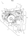
- Figures 1 , 2a to 2c illustrate an exemplary embodiment of part of a beverage preparation machine 1 in accordance with the invention.
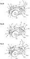
- Machine 1 has a capsule positioner 40 shown in its environment in Fig. 1 and in different configurations in Figs 2a to 2c .
- positioner 40 is ready to receive a capsule 20.
- positioner 40 has received capsule 20 and holds it.
- positioner 40 is shown in a configuration in which it has released capsule 20.
- Machine 1 includes: a capsule ingredient processing module 15 that can be mounted in a frame 15'.
- Processing module 15 is associated with a passage 2 for the transfer of a capsule 20 along a direction 2' from positioner 40 to processing module 15.
- Capsule positioner 40 can have at least one movable member 45a,45b which delimits a seat 44 for receiving capsule 20, member(s) 45a,45b being movable from (a) a position for receiving and holding said capsule to (b) a position for releasing said capsule into the passage and vice versa.
- Capsule 20 (shown in Fig. 2b ) is of the type described above under the header "field of the invention".
- Capsule 20 may have a container-body 21, e.g. a generally cup-shaped body, having a flange 23 at a rim of body 21 to which a lid 22 is attached, in particular sealed.
- Suitable capsules are for example disclosed in EP 0 512 468 und EP 0 512 470 .
- module 15 can have a chamber formed by a closure of assemblies 16,17 for receiving and housing therein capsule 20 supplied into machine 1 via passage 2.
- Processing module 15 may be configured to circulate a liquid into the chamber, typically for mixing with the ingredient in particular for brewing the capsule's ingredient.
- the chamber is delimited by a first assembly 16, e.g. an upstream assembly, and a second assembly 17, e.g. a downstream assembly.
- one assembly 16 is a water injection assembly and another assembly is a beverage dispensing assembly 17.
- assembly 16 forms a cage for receiving capsule 20 and assembly 17 forms a beverage delivery plate associated with a beverage outlet (not shown).
- assemblies 16,17 are shown in their spaced apart open position prior to enclosing or capturing capsule 20.
- the chamber 16,17 may be configured for holding and housing a capsule 20 containing a flavouring ingredient, such as tea or coffee or chocolate or powder milk. As mentioned above.
- a flavoured beverage may be prepared by circulating a carrier liquid, such as water, into the ingredient chamber to flavour the liquid by exposure to the flavouring ingredient held in chamber 16,17.
- a carrier liquid such as water
- First and second assemblies 16,17 can be relatively movable between a processing configuration for housing therein capsule 20 and a transfer configuration for inserting such capsule into processing module 15 and/or for evacuation thereof from processing module 15.
- An automatic ingredient recognition system may be used to parameterize and adjust the processing of the capsule automatically in line with the recognized capsule type.
- first and second assemblies 16,17 delimiting the ingredient chamber may include a capsule opener such as blades and/or a tearing tool, e.g. a plate with a tearing profile, for instance as known from NespressoTM machines. See for example EP 0 512 468 und EP 0 512 470 .
- Beverage machine 1 typically includes one or more of the following components:
- processing module 15 includes or is connected to an upstream fluid arrangement, e.g. incorporating a liquid driver, such as a pump 19, and a thermal conditioner, such as a heater 18, for circulating thermally conditioned liquid, such as water, from a source, e.g. a liquid reservoir, into the ingredient processing chamber.
- a liquid driver such as a pump 19
- a thermal conditioner such as a heater 18, for circulating thermally conditioned liquid, such as water, from a source, e.g. a liquid reservoir, into the ingredient processing chamber.
- upstream fluid arrangements are disclosed in WO 2009/074550 and in WO 2009/130099 .
- the heater may be a thermoblock or an on demand heater (ODH), for instance an ODH type disclosed in EP 1 253 844 , EP 1 380 243 and EP 1 809 151 .
- ODH on demand heater
- Suitable brewing units delimiting brewing chambers and suitable capsule management are for example disclosed in WO 2005/004683 , WO2007/135136 and WO 2009/043630 , which are hereby incorporated by way of reference.
- Suitable fluid circuits of processing modules are for instance disclosed in WO 2009/074550 and WO 2009/130099 , which are hereby incorporated by way of reference.
- Control unit configurations and connections are for example disclosed in WO 2009/043851 and WO 2009/043865 .
- processing module 15 typically includes a downstream fluid arrangement leading into an outlet for dispensing beverage to a user, e.g. to an area for placing a user-cup or a user-mug, the beverage formed in the brewing chamber containing the ingredient mixed with the circulating liquid.
- the dispensing area may be delimited at the bottom by a support surface for holding a user cup or mug.
- support surfaces are well known in the art, e.g. as disclosed in EP 1 867 260 and WO 2009/074557 .
- machine 1 (partly illustrated) has a housing 10, capsule positioner 40 being located at a top part of housing 10.
- Positioner 40 may be integral with or simply associated to housing 10, e.g. assembled or juxtaposed thereto.
- Movable member(s) 45a,45b may be manually or automatically or semi-automatically actuated from the receiving and holding position to the releasing position and/or vice versa.
- a movable member 45a,45b may be driven by an actuator 46, in particular by a motor 461 and a transmission arrangement 462,463.
- Such motor 461 can be controlled by a control unit ⁇ C, in particular a control unit that controls heater 18 and pump 19 and possibly other machine functions.
- Motor 461 may also be used to relatively move assemblies 16,17.
- Transmission arrangement 462,463 may include a gear transmission 462, such as a toothed gear transmission coupled to a lever transmission 463.
- a cam and/or belt transmission could also have be used.
- the gear transmission 462 includes cooperating toothed gears 462a-462c.
- the toothed gears can comprise a worm drive 462a mounted on the rotor of motor 461 which drives via at least one worm wheel 462b a toothed wheel 462c.
- Transmission arrangement 462,463 can include a lever transmission 463 that has a connecting rod 463a pivotally mounted to wheel 462c and driving a shaft 463b which in turn drives lever 463c pivotally mounted at an extremity 463c'.
- Lever 463c may be elastically constrained against driving shaft 463b.
- the lever may include an elongated guiding groove in which the shaft can slide.
- Another extremity of lever 463 can be connected to a connector 452 of movable member 45a,45b to drive it between the receiving and holding position and the releasing position.
- Connector 452 can form a protrusion extending and into a groove of the lever's extremity and sliding therein.
- Movable member 45a,45b may be supported by frame 15', e.g. via feet 453 of member 45a,45b.
- a spring element may be connected to at least one of feet 453 to urge member 45a,45b into the receiving and holding position or into the releasing position.
- Movable member 45a,45b may be pivotally mounted at pivoting location 451.
- Location 451 may be located between seat 44 and connector 452. Alternatively, the connector may be located between the pivoting location and the seat (not shown).
- Movable member(s) 45a,45b of capsule positioner 40 may be arranged to: hold capsule 20 generally vertically above passage 2 in the receiving and holding position ( Fig. 2b ) ; and drop capsule 20 generally vertically from capsule positioner 40 into passage 2 in the releasing position ( Fig. 2c ).
- Transfer direction 2' may be generally straight and generally vertical extending from the position of capsule 20 when held by movable member(s) 45a,45b.
- Capsule 20 may be transferred via passage 2 to an intermediate position for being handled by processing module 15, in particular by assemblies 16,17, into an extraction configuration in processing module 15, in particular inbetween assemblies 16,17.
- processing module 15, e.g. assemblies 16,17 may bring capsule 20 into a removal configuration from where capsule 20 is manually and/or preferably automatically, e.g. under the effect of gravity or another force, ejected for instance to a used capsule collector.
- Member(s) 45a,45b can be pivotable between (a) the receiving and holding position and (b) the releasing position, in particular pivotable about a pivoting axis A that is distant from seat 44.
- Member(s) 45a,45b may be pivotable from (a) the receiving and holding position to (b) the releasing position by an angle of less than 100 deg, in particular less than 75 deg, such as less than 45 deg, more particularly less than 30 deg, for example less than 15 or 10 deg. In the embodiment illustrated in Figs 2a to 2c , the angle is of the order of 10-15 deg.
- Machine 1 may have a stationary outer envelope 10, such a frame or a housing portion 10 or virtual boundaries, at which movable member(s) 45a,45b is/are located in the receiving and holding position, movable member(s) 45a,45b being confined within envelope 10 in the releasing position. As illustrated in Figs 1 to 2c , member(s) 45a,45b may be arranged to move inside and/or underneath housing portion 10.
- Machine 1 can have a mouth 11, in particular a mouth in outer envelope 10 or a virtual mouth (the latter being indicated in Figs 3a ), for an insertion of capsule 20 into seat 44 in the receiving and holding position, movable member(s) (45a,45b) being movable away from mouth 11 when moved from the receiving and holding position to the releasing position.
- movable member(s) 45a,45b form(s) (a) trap door(s) adjacent to the mouth.
- Movable member(s) 45a,45b may be pivotable:
- Capsule positioner 40 can comprise two or more movable members 45a,45b that are movable together above passage 2 into the receiving and holding position and movable apart from above passage 2 into the releasing position.
- capsule positioner 40 has two movable members 45a,45b, in particular generally plate-shaped members optionally delimiting a recess forming a bottom of seat 44, each having a pivoting axis A, movable members 45a,45b being in a general scissor configuration that can be closed into the receiving and holding position and opened into the releasing position.
- two members 45a,45b are shown to be pivotable in opposite directions, each being pivotable about a respective axis A.
- Seat 44 can have a shape configured to generally match a shape of capsule 20, in particular a shape that is generally conical or cylindrical to match a correspondingly shaped body 21 of capsule 20.
- Seat 44 may have guides 45c arranged to match a correspondingly shaped capsule flange 23, e.g. a rim 23 of a capsule body 21 which is joined to a lid 22 closing body 21.
- Machine 1 may include guiding means 30 for guiding capsule 20 in passage 2.
- the guiding means can have guide members 31 guiding a capsule flange 23 and/or being associated with stop members 32 for stopping capsule 20, e.g. stopping capsule flange 23, in a position for being handled by processing module 15.
- Capsule positioner 40 can have a seat 44 that has guides 45c for guiding capsule 20, in particular capsule flange 23, into guiding means 30 in passage 2.
- guide members 31 are part of or delimit part of passage 2.
- Guide members 31 may be associated with at least one of assemblies 16,17.
- guide members have a connecter, e.g. a receiving recess 33, for securing at least one of assemblies 16,17, for example a generally plate-shaped assembly 17, as shown in Figs 1 and 2a .
- capsule positioner 40 and passage 2 and processing module 15 are adapted to handle a capsule 20 of a first type and of a second type.
- they may be configured so that:
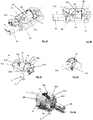
- FIGs 3a to 3e in which the same numeric references designate the generally same or similar elements, another exemplary embodiment of a capsule positioner 40 is illustrated.
- Machine 1 includes a capsule positioner 40 having at least one member 45a,45b that is pivotable about a pivoting axis A from a position for receiving capsule 20 and holding capsule 20 ( Figs 3a to 3d ) to a position for releasing capsule 20 (not shown) into passage 2 via an transitional position of capsule positioner 40 ( Fig. 3e ).
- Pivoting axis A extends through an area 44' occupied by capsule 20 when held by pivotable member(s) 45a,45b, as illustrated in Figs 3a and 3b .
- Pivoting axis A of pivotable member(s) may extend: generally perpendicularly to transfer direction 2' of capsule 20 along passage 2; and/or generally parallelly to a machine housing at the capsule positioner (the housing is not shown in Figs 3a to 3e but is analogous to the one shown in Fig. 1 ).
- pivoting axis A may extend generally parallelly to the passage or generally perpendicularly to the machine housing (not shown).
- Area 44' can be delimited, at least in part, by a capsule reception and holding recess 44 formed by the pivotable member(s) 45a,45b.
- pivotable member(s) 45a,45b can be in the shape of and mounted like a swing, recess 44 being for instance delimited by the base (seat) and suspending arms of the swing; and pivoting axis A being at a location 45a',45a'';45b',45b'' of the suspending arms at a distance of the seat.
- At least one pivotable member 45a,45b may delimit at least part of a seat 44 for receiving and holding capsule 20.
- Seat 44 can have a shape configured to generally match a shape of capsule 20.
- seat 44 has a shape that is generally conical or cylindrical to match a correspondingly shaped capsule body 21.
- seat 44 may have guides 45c arranged to match a correspondingly shaped capsule flange 23, in particular a rim 23 of a capsule body 21 which is joined to a lid 22 closing body 21.
- capsule positioner 40 comprises a pair of pivotable members 45a,45b delimiting at least part of seat 44.
- Members 45a,45b may be pivotable in opposite pivoting direction about pivoting axis A.
- Pivotable member(s) 45a,54b may form a shell, in particular a shell pivotally mounted at one or two extremities 45a',45a'';45b',45b'' of the shell.
- At least one pivotable member 45a,54b can be located: in its member position for receiving and holding capsule 20, between area 44' and passage 20; and in its position for releasing capsule 20 into passage 2, above area 44' and/or sideways said area 44' and passage 20.
- Movable member(s) 45a,45b of capsule positioner 40 may be arranged to: hold capsule 20 generally vertically above passage 2 in the receiving and holding position; and drop capsule 20 generally vertically from capsule positioner 40 into passage 2 in the releasing position.
- machine 1 can comprise guiding means for guiding capsule 20 in passage 2.
- Guiding means may comprise guide members that are dimensioned to guide capsule flange 23 and/or that are associated with stop members for stopping capsule 20, in particular stopping capsule flange 23, in a position for being handled by the processing module.
- Figs 3a to 3e illustrate how a small capsule 20 is received, held and released from capsule positioner 40, capsule flange 23 being received by guides 45c and capsule body 21 occupying only part of seat 44; the flange of a long capsule could be received in guides 45c and the long capsule body could extend over the entire seat 44.
- the processing module should then be so adapted that the assemblies and chamber are adjusted to the dimensions of the large or small capsule, for instance as taught in co-pending applications EP 2012187716.1 , EP 2012187717.9 , EP 2012187718.7 , EP 2012197961.1 and EP 2012189153.5 .
- capsule seat 44 formed by pivotable members 45a,45 can be mounted in a frame 42 that may be integral with or adjacent to the (not shown) envelope of beverage machine 1.
- Capsule positioner 40 has two movable pivotable members in the shape of shells 45a,45b forming the base of capsule seat 44 when capsule positioner 40 is in the position illustrated in Figs 3a to 3d .
- the two movable shells 45a,45b may be provided with notches 45c for guiding the introduction and the positioning of a capsule 2 into seat 44.
- the shells may be displaced by a motorized mechanism 46 to switch the position illustrated in Figs 3a to 3d , i.e.
- each shell may be rotated along a longitudinal axis A by motorized mechanism 46 to move each shell around capsule 20 from below capsule 20 to above capsule 20 so as to allow capsule 20 to be released from seat 44, for example by allowing capsule 20 to fall down into brewing unit formed of corresponding assemblies 16,17 through transfer passage 2.
- capsule positioner 40 is positioned at the upper part of housing 10 of beverage machine 1 to let a capsule fall into the passage 20 under the effect of gravity, when capsule positioner 40 is brought into its capsule releasing position.
- the shells may be mechanically linked by a mechanical coupling means with or associated with a movable part of the brewing unit so as to switch between the receiving and holding position and the releasing position depending on whether the brewing unit is open or closed or moving between these two states.
- Guides 45c formed in the shells and surrounding capsule seat 44 are disposed to ease the positioning of capsule 20 by a user when capsule positioner 40 is in the receiving and holding position, and/or to improve the holding of capsule 20 in seat 44.
- guides 45c may be arranged to guide the movement of capsule 20 when capsule positioner 40 is switched to its releasing position, and to prevent a capsule 20 inserted into seat 44 to be translated within capsule positioner 40, for example when capsule positioner 40 is switched from the receiving and holding position to the releasing position.
- Beverage machine 1 may comprise a capsule-length detector 47 and/or a sensor 48 for sensing the position of pivotable member 45a.
- Capsule detector 47 can be adapted to detect the presence on capsule seat 44 of capsule 20 and to identify whether the detected capsule is of a first or a second type different to the first type. More particularly, the capsule-length detector may be configured to determine the type of the capsule according to the length of the capsule.
- the capsule-length detector may be configured to detect the presence of a metallic capsule in the seat, and then, determine if the detected capsule is of the first type or the second type by checking if the maximum length of said capsule along its axis of symmetry is sensibly equal to a first length L1 or to a second length L2 corresponding respectively to the first capsule type and second capsule type.
- a detection is for example disclosed in co-pending application EP 2012187762.5 .
- capsule 20 may be inserted into processing module 15 of machine 1 in the following manner:
- Capsule 20 can be immobilized in guide 31 on stop members 32, for example flange 23 of capsule 20 may rest on stop members 32 to immobilize capsule 20. In this position, capsule 20 is in position to be handled by processing module 15.
- a beverage can be prepared after transferring the capsule 20 to the chamber 16,17 of processing module 15, for example by capturing or enclosing capsule 20 by assemblies 16,17 that are relatively moved from an open position to a closed position (not shown).
- Machine 1 may have a collector receptacle (not shown) for collecting used ingredient capsules, such as tea leaves or ground coffee within used capsules, and waste liquid.
- Collector receptacle may be insertable, e.g. slidable, into a cavity formed in machine 1 and removable therefrom for servicing, e.g. emptying the solids and/or liquids contained therein.
Landscapes
- Engineering & Computer Science (AREA)
- Food Science & Technology (AREA)
- Mechanical Engineering (AREA)
- Health & Medical Sciences (AREA)
- Nutrition Science (AREA)
- Life Sciences & Earth Sciences (AREA)
- Chemical & Material Sciences (AREA)
- Polymers & Plastics (AREA)
- Apparatus For Making Beverages (AREA)
Claims (18)
- Machine (1) pour la préparation d'une boisson à partir d'une capsule d'ingrédient (20), comprenant :- un module de traitement de capsules d'ingrédient (15) ayant une chambre (16, 17) pour traiter ladite capsule à l'intérieur de celle-ci ;- un passage (2) pour un transfert de ladite capsule à la chambre ; et- un dispositif de positionnement de capsule (40) ayant au moins un élément (45a, 45b) qui délimite un siège (44) pour recevoir une capsule, le ou les éléments mobiles étant mobiles d'une position pour recevoir et maintenir ladite capsule vers une position pour libérer ladite capsule dans le passage,le ou les éléments mobiles (45a, 45b) étant agencés pour :- maintenir ladite capsule généralement verticalement au-dessus du passage dans la position de réception et de maintien ; et- laisser tomber ladite capsule généralement verticalement depuis le dispositif de positionnement de capsule dans le passage dans la position de libération, facultativement, le transfert de ladite capsule s'étendant le long d'une direction (2') généralement droite et généralement verticale à partir d'une position de ladite capsule lorsqu'elle est maintenue par le ou les éléments mobiles le long du passage (2),caractérisée en ce que la machine comprend un moyen de guidage (30) pour guider la capsule (20) dans le passage (2), le moyen de guidage comprenant des éléments de guidage (31) pour guider une bride de capsule (23), le dispositif de positionnement de capsule (40) comportant un siège (44) qui a des guides (45c) pour guider ladite bride dans le moyen de guidage (30) dans le passage (2).
- Machine selon la revendication 1, dans laquelle ledit au moins un élément (45a, 45b) peut pivoter entre :- la position de réception et de maintien ; et- la position de libération,de préférence peut pivoter autour d'un axe de pivotement (A) qui est distant dudit siège.
- Machine selon la revendication 1 ou 2, dans laquelle ledit au moins un élément (45a, 45b) peut pivoter de la position de réception et de maintien à la position de libération d'un angle inférieur à 100 degrés, en particulier inférieur à 75 degrés, comme inférieur à 45 degrés, plus particulièrement inférieur à 30 degrés, par exemple inférieur à 15 ou 10 degrés.
- Machine selon une quelconque revendication précédente, qui comporte une enveloppe externe fixe (10), comme une partie de cadre ou de boîtier (10) ou des frontières virtuelles, au niveau de laquelle le ou les éléments mobiles (45a, 45b) sont situés dans la position de réception et de maintien, le ou les éléments mobiles dans la position de libération étant confinés à l'intérieur de l'enveloppe.
- Machine selon une quelconque revendication précédente, qui présente une embouchure (11), notamment une embouchure dans une enveloppe externe (10) d'une telle machine (1), pour une insertion de ladite capsule (20) dans le siège (44) dans la position de réception et de maintien, le ou les éléments mobiles (45a, 45b) étant mobiles à l'opposé de l'embouchure lorsqu'ils sont déplacés de la position de réception et de maintien vers la position de libération, le ou les éléments mobiles (45a, 45b) formant facultativement une ou plusieurs portes de trappe adjacentes à l'embouchure.
- Machine selon une quelconque revendication précédente 5, dans laquelle le ou les éléments mobiles (45a, 45b) peuvent pivoter :- à l'opposé d'une embouchure (11), en particulier une embouchure dans une enveloppe externe (10) d'une telle machine (1), autour d'un axe de pivotement (A) généralement perpendiculaire à l'embouchure, facultativement distant de l'embouchure ou généralement parallèle à l'embouchure ; et/ou- autour d'un axe (A) dudit au moins un élément pivotant, axe qui s'étend :- généralement parallèlement à une direction de transfert (2') de ladite capsule (20) le long du passage (2) ; et/ou- généralement perpendiculairement à un boîtier de machine (10) au niveau du dispositif de positionnement de capsule (40) et/ou généralement parallèlement au passage,
- Machine selon une quelconque revendication précédente, dans laquelle le dispositif de positionnement de capsule (40) comprend deux éléments mobiles ou plus (45a, 45b) qui sont mobiles ensemble au-dessus du passage (2) vers la position de réception et de maintien et sont mobiles séparément depuis le dessus du passage (2) vers la position de libération.
- Machine selon la revendication 7, dans laquelle le dispositif de positionnement de capsule (40) comprend deux éléments mobiles (45a, 45b), en particulier des éléments généralement en forme de plaque, chacun ayant un axe de pivotement (A), les éléments mobiles étant dans une configuration générale de ciseaux qui peuvent être fermés dans la position de réception et de maintien et ouverts dans la position de libération.
- Machine selon la revendication 7 ou 8, qui comprend deux éléments (45a, 45b) pouvant pivoter dans des directions opposées autour de l'axe de pivotement (A).
- Machine selon une quelconque revendication précédente, dans laquelle le siège (44) a une forme conçue pour correspondre généralement à une forme de ladite capsule (20), en particulier une forme généralement conique ou cylindrique pour correspondre à un corps (21) de forme correspondante de ladite capsule (20).
- Machine selon la revendication 10, dans laquelle le siège (44) présente des guides (45c) agencés pour correspondre à une bride de capsule (23) de forme correspondante, en particulier un rebord (23) d'un corps de capsule (21) qui est relié à un couvercle (22) fermant le corps (21).
- Machine selon une quelconque revendication précédente, dans laquelle les moyens de guidage (30) sont associés à des éléments de butée (32) pour arrêter ladite capsule, en particulier arrêter la bride de capsule, dans une position pour être manipulée par le module de traitement (15).
- Machine selon une quelconque revendication précédente, dans laquelle le dispositif de positionnement de capsule (40) et le passage (2) et le module de traitement (15) sont adaptés pour manipuler une capsule (20) d'un premier type et d'un second type, facultativement :- le dispositif de positionnement de capsule comprenant un premier guide pour guider une bride du premier type de capsule et un second guide pour guider une bride du second type de capsule ; et/ou- le module de traitement (15) comprenant des ensembles (16, 17) adaptés pour une insertion sélective d'une capsule (20) d'un premier type ou d'un second type lorsque les ensembles sont en position ouverte, le module de traitement (15) étant agencé pour adapter la configuration des ensembles (16, 17) et/ou de la chambre d'infusion (16, 17) en fonction du type de la capsule insérée (20).
- Machine selon une quelconque revendication précédente, dans laquelle le dispositif de positionnement de capsule (40) est situé au-dessus du module de traitement d'ingrédient (15) et du passage (2), le dispositif de positionnement de capsule (40), le module de traitement d'ingrédient (15) et le passage (2) étant facultativement conçus de sorte que ladite capsule (20) puisse être entraînée par gravité du dispositif de positionnement de capsule au module de traitement.
- Procédé d'insertion d'une capsule d'ingrédient (20) dans le module de traitement (15) de la machine (1) définie dans une quelconque revendication précédente, pour la préparation d'une boisson à partir de la capsule (20), comprenant les étapes consistant à :- recevoir et maintenir la capsule (20) par ledit au moins un élément mobile (45a, 45b) du dispositif de positionnement de capsule (40) dans la position de réception et de maintien, moyennant quoi la capsule est reçue et maintenue par l'élément mobile généralement verticalement au-dessus du passage dans la position de réception et de maintien ;- déplacer ledit au moins un élément (45a, 45b) vers la position de libération et libérer ladite capsule (20) dans le passage (2), moyennant quoi la capsule est amenée à tomber généralement verticalement depuis le dispositif de positionnement de capsule dans le passage ; et- transférer la capsule (20) par le passage (2) vers la chambre (16, 17) du module de traitement (15).caractérisé en ce que la machine comprend un moyen de guidage (30) pour guider la capsule (20) dans le passage (2), le moyen de guidage comprenant des éléments de guidage (31) pour guider une bride de capsule (23), le dispositif de positionnement de capsule (40) comportant un siège (44) qui présente des guides (45c) pour guider ladite bride dans le moyen de guidage (30) dans le passage (2),
moyennant quoi le procédé comprend en outre le guidage de la bride de la capsule depuis les guides (45c) vers les éléments de guidage (30). - Procédé selon la revendication 15, dans lequel une boisson est préparée après le transfert de la capsule (20) à la chambre (16, 17) du module de traitement (15).
- Combinaison d'une machine (1) et d'une capsule (20), dans laquelle la machine et la capsule sont agencées pour réaliser le procédé défini dans la revendication 15 ou 16 et/ou dans laquelle la machine est une machine selon l'une quelconque des revendications 1 à 14 et dans laquelle la capsule est : maintenue généralement verticalement au-dessus du passage dans la position de réception et de maintien ; et la capsule étant amenée à tomber généralement verticalement depuis le dispositif de positionnement de capsule dans le passage dans la position de libération.
- Utilisation d'une capsule (20) pour :- être insérée dans une machine telle que définie dans l'une quelconque des revendications 1 à 14- être insérée dans une machine selon un procédé tel que défini dans la revendication 15 ou 16, ou- produire une combinaison telle que définie dans la revendication 17.
Priority Applications (1)
| Application Number | Priority Date | Filing Date | Title |
|---|---|---|---|
| EP13733313.4A EP2906089B1 (fr) | 2012-10-09 | 2013-07-03 | Machine pour préparer des boissons |
Applications Claiming Priority (3)
| Application Number | Priority Date | Filing Date | Title |
|---|---|---|---|
| EP12187762 | 2012-10-09 | ||
| EP13733313.4A EP2906089B1 (fr) | 2012-10-09 | 2013-07-03 | Machine pour préparer des boissons |
| PCT/EP2013/064001 WO2014056641A1 (fr) | 2012-10-09 | 2013-07-03 | Machine pour la préparation de boissons |
Publications (2)
| Publication Number | Publication Date |
|---|---|
| EP2906089A1 EP2906089A1 (fr) | 2015-08-19 |
| EP2906089B1 true EP2906089B1 (fr) | 2018-11-07 |
Family
ID=47172306
Family Applications (3)
| Application Number | Title | Priority Date | Filing Date |
|---|---|---|---|
| EP13734059.2A Withdrawn EP2906090A1 (fr) | 2012-10-09 | 2013-07-03 | Distributeur automatique de boisson |
| EP13733313.4A Active EP2906089B1 (fr) | 2012-10-09 | 2013-07-03 | Machine pour préparer des boissons |
| EP13766558.4A Active EP2906091B1 (fr) | 2012-10-09 | 2013-09-27 | Machine pour préparer des boissons |
Family Applications Before (1)
| Application Number | Title | Priority Date | Filing Date |
|---|---|---|---|
| EP13734059.2A Withdrawn EP2906090A1 (fr) | 2012-10-09 | 2013-07-03 | Distributeur automatique de boisson |
Family Applications After (1)
| Application Number | Title | Priority Date | Filing Date |
|---|---|---|---|
| EP13766558.4A Active EP2906091B1 (fr) | 2012-10-09 | 2013-09-27 | Machine pour préparer des boissons |
Country Status (11)
| Country | Link |
|---|---|
| US (3) | US20150265091A1 (fr) |
| EP (3) | EP2906090A1 (fr) |
| JP (3) | JP2015534487A (fr) |
| CN (3) | CN104837384B (fr) |
| AR (1) | AR092963A1 (fr) |
| AU (3) | AU2013329853A1 (fr) |
| BR (3) | BR112015007596A2 (fr) |
| CA (3) | CA2887222A1 (fr) |
| IN (3) | IN2015DN02981A (fr) |
| RU (3) | RU2634679C2 (fr) |
| WO (3) | WO2014056641A1 (fr) |
Families Citing this family (61)
| Publication number | Priority date | Publication date | Assignee | Title |
|---|---|---|---|---|
| DE202011001661U1 (de) * | 2011-01-19 | 2011-06-09 | Mahlich, Gotthard, 61476 | Brüh- oder Zubereitungskammer für ein Getränkezubereitungsgerät |
| WO2015086371A1 (fr) * | 2013-12-11 | 2015-06-18 | Nestec S.A. | Machine à boisson avec butée de capsule pivotante |
| CN105813512B (zh) * | 2013-12-20 | 2020-06-16 | 皇家飞利浦有限公司 | 消耗品识别系统、消耗品集合和饮料分配器 |
| ES2875040T3 (es) | 2014-07-09 | 2021-11-08 | Nestle Sa | Acoplamiento de un dispositivo para conectar una máquina de bebidas a una red de distribución |
| EP3166455B1 (fr) | 2014-07-09 | 2020-09-30 | Société des Produits Nestlé S.A. | Dispositif de raccordement d'une machine à boisson à un réseau de distribution avec interruption de l'écoulement sécurisée |
| CA2949901C (fr) * | 2014-07-09 | 2021-11-23 | Nestec S.A. | Unite de traitement de capsules de machine de preparation de boissons |
| EP3166457B1 (fr) | 2014-07-09 | 2019-10-09 | Société des Produits Nestlé S.A. | Dispositif de raccordement d'une machine à boissons à un réseau de distribution avec surveillance sécurisée |
| WO2016005349A1 (fr) | 2014-07-09 | 2016-01-14 | Nestec S.A. | Accessoire permettant d'alimenter automatiquement une machine à boissons en liquide à partir d'un réseau de distribution |
| AU2015306120B2 (en) | 2014-08-21 | 2019-06-27 | Société des Produits Nestlé S.A. | Inter-operable capsule dispensing unit and beverage preparation machine |
| AU2015330350A1 (en) | 2014-10-08 | 2017-02-23 | Société des Produits Nestlé S.A. | Extraction unit of beverage preparation machine |
| BR112017006875A2 (pt) * | 2014-10-08 | 2017-12-12 | Nestec Sa | máquina para o preparo de bebidas reconfigurável |
| GB201418881D0 (en) * | 2014-10-23 | 2014-12-03 | Mars Inc | Beverage preparation with pressurized liquid |
| CN105982551B (zh) * | 2015-02-02 | 2019-11-12 | 深圳市西啡科技有限公司 | 兼容式胶囊咖啡机的酿造系统 |
| CA3001089A1 (fr) | 2015-11-11 | 2017-05-18 | Nestec S.A. | Raccordement facile d'un reservoir de liquide a une machine a boissons |
| EP3175745A1 (fr) * | 2015-12-01 | 2017-06-07 | Qbo Coffee GmbH | Module d'ebouillantage, module de detection de capsule et machine de preparation de boissons |
| DE102016101223A1 (de) * | 2016-01-25 | 2017-07-27 | Eugster/Frismag Ag | Getränkezubereitungsvorrichtung, System sowie Betriebsverfahren |
| WO2017191018A1 (fr) * | 2016-05-04 | 2017-11-09 | Nestec S.A. | Machine permettant la préparation d'une boisson |
| WO2018001750A1 (fr) | 2016-06-30 | 2018-01-04 | Nestec Sa | Machine de préparation de boissons à pompe commandée |
| NL2017281B1 (en) | 2016-08-03 | 2018-02-14 | Douwe Egberts Bv | System for preparing a beverage |
| NL2017278B1 (en) | 2016-08-03 | 2018-02-14 | Douwe Egberts Bv | System, apparatus, method, capsule and kit of capsules for preparing a beverage |
| NL2017282B1 (en) * | 2016-08-03 | 2018-02-14 | Douwe Egberts Bv | System for preparing a beverage |
| NL2017283B1 (en) * | 2016-08-03 | 2018-02-14 | Douwe Egberts Bv | System and apparatus for preparing a beverage |
| NL2017284B1 (en) | 2016-08-03 | 2018-02-14 | Douwe Egberts Bv | System and method for preparing a beverage field and background |
| NL2019218B1 (en) * | 2016-08-03 | 2018-07-06 | Douwe Egberts Bv | Capsule, system and use of the system for preparing double beverages like a double espresso, a double lungo and a double ristretto |
| WO2018026280A1 (fr) * | 2016-08-03 | 2018-02-08 | Koninklijke Douwe Egberts B.V. | Capsule, système et utilisation du système pour préparer des boissons doubles comme un double expresso, un double café allongé et un double café court |
| NL2017277B1 (en) | 2016-08-03 | 2018-02-14 | Douwe Egberts Bv | Apparatus and method for preparing a beverage and system comprising the apparatus and an exchangeable capsule |
| NL2017285B1 (en) | 2016-08-03 | 2018-02-14 | Douwe Egberts Bv | System, apparatus, method, capsule and kit of capsules for preparing a beverage |
| NL2017279B1 (en) | 2016-08-03 | 2018-02-14 | Douwe Egberts Bv | System for preparing a beverage |
| AU2017323398B2 (en) * | 2016-09-09 | 2022-12-08 | Société des Produits Nestlé S.A. | Beverage machine with ergonomic handling |
| US10786109B2 (en) * | 2016-09-28 | 2020-09-29 | Haier Us Appliance Solutions, Inc. | Single serve beverage dispenser for an appliance |
| RU2754461C1 (ru) | 2016-11-09 | 2021-09-02 | Пепсико, Инк. | Устройства, способы и системы для приготовления газированных напитков |
| WO2018219988A1 (fr) | 2017-06-01 | 2018-12-06 | Nestec Sa | Machine à boisson dotée d'un interrupteur ergonomique |
| WO2018219985A1 (fr) | 2017-06-01 | 2018-12-06 | Nestec Sa | Machine à boisson dotée d'une tête de distribution pouvant être rangée |
| CN110691538B (zh) | 2017-06-01 | 2023-03-28 | 雀巢产品有限公司 | 具有可收缩界面的饮料机器 |
| IT201700060684A1 (it) * | 2017-06-01 | 2018-12-01 | Caffitaly System Spa | Dispositivo di acquisizione di immagini e apparecchiatura per la preparazione di una bevanda, comprendente detto dispositivo di acquisizione di immagini |
| WO2018219989A1 (fr) | 2017-06-01 | 2018-12-06 | Nestec Sa | Machine à boisson dotée d'un pied de stabilisation |
| US20200100618A1 (en) | 2017-06-13 | 2020-04-02 | Societe Des Produits Nestle S.A | Beverage preparation machine with capsule recognition |
| EP3687346A1 (fr) | 2017-09-25 | 2020-08-05 | Société des Produits Nestlé S.A. | Machines à boissons à modularité |
| PT3687347T (pt) | 2017-09-25 | 2023-09-07 | Nestle Sa | Máquinas de bebidas com um módulo removível |
| PT3501346T (pt) | 2017-12-22 | 2020-10-29 | Nestle Sa | Distribuidor de porção para distribuir itens de bebidas em porções |
| CN108128613B (zh) * | 2018-01-19 | 2023-08-04 | 武汉大坦智能装备科技有限公司 | 球状胶囊高速顶出植料机 |
| CN111655093B (zh) | 2018-02-09 | 2023-01-10 | 雀巢产品有限公司 | 用于制备和分配饮料的机器 |
| WO2019175227A1 (fr) | 2018-03-14 | 2019-09-19 | Societe Des Produits Nestle S.A. | Machine à boissons dotée d'une configuration d'extraction d'ingrédient non homogène |
| US20210000288A1 (en) | 2018-03-14 | 2021-01-07 | Societe Des Produits Nestle S.A. | Beverage machine with a partly closed dispensing face |
| CN111801034B (zh) | 2018-03-14 | 2023-08-04 | 雀巢产品有限公司 | 具有受控流出孔的饮料机器 |
| WO2019175230A1 (fr) | 2018-03-14 | 2019-09-19 | Societe Des Produits Nestle S.A. | Machine à boisson avec perçage de capsule commandé |
| EP3831251B1 (fr) * | 2018-08-01 | 2023-02-01 | Novadelta-Comércio e Industria de Cafés, Lda. | Système de distribution de boissons avec récipients pour boisson à maintien ergonomique, et son procédé de fonctionnement |
| CA3114174A1 (fr) | 2018-09-27 | 2020-04-02 | Societe Des Produits Nestle Sa | Machine a boissons avec distribution d'actionnement |
| AU2019348522A1 (en) | 2018-09-27 | 2021-02-18 | Société des Produits Nestlé SA | Adaptive service unit of a beverage machine |
| EP3628195A1 (fr) | 2018-09-27 | 2020-04-01 | Société des Produits Nestlé S.A. | Machine de préparation de boissons avec détection de récipient |
| ES2939255T3 (es) * | 2018-10-30 | 2023-04-20 | Evoca Spa | Aparato para la restauración de la forma de una cápsula de preparación de bebida |
| NL2022190B1 (en) | 2018-12-12 | 2020-07-03 | Douwe Egberts Bv | Air purge groove |
| JP7475348B2 (ja) * | 2018-12-12 | 2024-04-26 | ソシエテ・デ・プロデュイ・ネスレ・エス・アー | カプセルを認識する飲料調製マシン |
| CN112021941B (zh) * | 2019-06-04 | 2022-04-15 | 广东美的生活电器制造有限公司 | 酿造装置和饮品机 |
| CN110367822B (zh) * | 2019-07-16 | 2024-01-12 | 深圳市西啡科技有限公司 | 一种冲泡装置及饮料机 |
| WO2021028472A1 (fr) | 2019-08-13 | 2021-02-18 | Eugster / Frismag Ag | Dispositif de préparation de boisson et procédé pour préparer une boisson au moyen d'une capsule portion d'un premier et d'un deuxième type, et système comprenant un dispositif de préparation de boisson et un ensemble capsule portion |
| WO2021156268A1 (fr) | 2020-02-05 | 2021-08-12 | Societe Des Produits Nestle S.A. | Machine de préparation de boisson à reconnaissance de capsule |
| BR112022013134A2 (pt) | 2020-02-05 | 2022-09-06 | Nestle Sa | Máquina para o preparo de bebidas com reconhecimento de cápsula |
| CN111449521A (zh) * | 2020-04-13 | 2020-07-28 | 长沙每日滋养健康科技有限公司 | 一种用于胶囊萃取机的废弃胶囊自动丢弃系统 |
| IT202100025913A1 (it) * | 2021-10-08 | 2023-04-08 | Caffitaly System Spa | Apparecchiatura per la preparazione di una bevanda tramite infusione di una sostanza alimentare |
| CN115191832A (zh) * | 2022-07-29 | 2022-10-18 | 广东亿龙电器科技有限公司 | 一种电动酿造装置 |
Citations (2)
| Publication number | Priority date | Publication date | Assignee | Title |
|---|---|---|---|---|
| WO2006013124A1 (fr) * | 2004-06-04 | 2006-02-09 | Sgl Italia S.R.L. | Percolateur pour faire une boisson |
| FR2907766A1 (fr) * | 2006-10-26 | 2008-05-02 | Seb Sa | Dispositif de stockage et de distribution de capsules pour preparation de boissons et machine a cafe comportant un tel dispositif |
Family Cites Families (105)
| Publication number | Priority date | Publication date | Assignee | Title |
|---|---|---|---|---|
| BE778159A (nl) * | 1972-01-18 | 1972-05-16 | Veken Germaine V D | Verpakking voor capsules voor het maken van aftreksels. |
| US4029003A (en) * | 1976-02-24 | 1977-06-14 | Adriana Manaresi | Device for the extemporary preparation of beverages |
| TW199884B (fr) | 1991-05-08 | 1993-02-11 | Sociere Des Produits Nestle S A | |
| AU1505192A (en) | 1991-05-10 | 1992-11-12 | Societe Des Produits Nestle S.A. | Sealed cartridge for the prepartion of a beverage |
| EP1000574A1 (fr) * | 1998-11-16 | 2000-05-17 | Societe Des Produits Nestle S.A. | Procédé et dispositif d'extraction d'une capsule fermée |
| ATE294522T1 (de) * | 1999-04-23 | 2005-05-15 | Fianara Int Bv | Einrichtung zum zuführen von abgepackten portionen gemahlenen kaffees in eine brüheinheit |
| US6459854B1 (en) | 2000-01-24 | 2002-10-01 | Nestec S.A. | Process and module for heating liquid |
| DK1208782T3 (da) * | 2000-11-28 | 2004-12-13 | Nestle Sa | Perkolationsindretning |
| ATE249777T1 (de) * | 2000-12-29 | 2003-10-15 | Sgl Italia Srl | Kaffeemaschine |
| CH694265A5 (fr) * | 2001-01-24 | 2004-10-29 | Monodor Sa | Dispositif d'injection d'eau pour un appareil pour la confection d'une boisson à partir d'une capsule contenant le produit à extraire. |
| US6832542B2 (en) * | 2001-03-23 | 2004-12-21 | Nestec S.A. | Method and device for preparing a hot beverage |
| US7063238B2 (en) * | 2001-06-29 | 2006-06-20 | Robert Hale | Cartridge ejector for a beverage dispensing machine |
| ITMI20011974A1 (it) * | 2001-09-21 | 2003-03-21 | Illycaffe Spa | Sistema per trasferire singole confezioni di caffe' da un contenitorealla camera di estrazione di una macchina per fare caffe' espresso |
| ITTO20010902A1 (it) * | 2001-09-21 | 2003-03-21 | Sgl Italia Srl | Macchina da caffe'. |
| ES2279783T3 (es) * | 2001-11-09 | 2007-09-01 | Societe Des Produits Nestle S.A. | Dispositivo y metodo para la seleccion y la extraccion de una capsula para la preparacion de una bebida. |
| US6729226B2 (en) | 2002-04-24 | 2004-05-04 | Joseph Mangiapane | Multiple beverage preparation device |
| ITTO20020481A1 (it) * | 2002-06-07 | 2003-12-09 | Sgl Italia Srl | Metodo e dispositivo di foratura di una capsula sigillata in una macchina da caffe'. |
| DK1380243T3 (da) | 2002-07-12 | 2008-08-25 | Nestec Sa | Indretning til opvarmning af en væske |
| EP1444932B1 (fr) * | 2003-02-07 | 2006-01-25 | Nestec S.A. | Module d'extraction à fermeture linéaire pour la préparation sous pression d'une boisson à partir d'une capsule |
| DE20302410U1 (de) * | 2003-02-13 | 2004-06-24 | Nestec S.A. | Kapselmagazineinheit mit Kapselmagazineinheitaufnahmeeinrichtung, insbesondere einer Espressomaschine |
| US7243597B2 (en) * | 2003-02-21 | 2007-07-17 | Nestec S.A. | Unit for the preparation of a foamy beverage from a capsule and an opening plunger |
| WO2004105564A1 (fr) * | 2003-05-27 | 2004-12-09 | Koninklijke Philips Electronics N.V. | Recipient a infusion, dispositif en mousse et appareil a fabriquer des boissons comprenant ledit recipient |
| US6955116B2 (en) * | 2003-06-13 | 2005-10-18 | Robert Hale | Beverage dispensing machine including cartridge ejector assembly |
| ATE367758T1 (de) * | 2003-06-25 | 2007-08-15 | Koninkl Philips Electronics Nv | Getränkezubereitungsvorrichtung mit verstellbarer brühkammer |
| EP1495702A1 (fr) * | 2003-07-10 | 2005-01-12 | Nestec S.A. | Dispositif pour l'extraction d'une capsule |
| US8327754B2 (en) * | 2003-07-22 | 2012-12-11 | The Coca-Cola Company | Coffee and tea pod |
| DK1500357T3 (da) * | 2003-07-23 | 2006-06-19 | Monodor Sa | Fremgangsmåde til tilberedning af en drik ud fra en kapsel og anordning til fremgangsmådens iværksættelse |
| EP1510158A1 (fr) * | 2003-08-25 | 2005-03-02 | Nestec S.A. | Dispositif et méthode pour la préparation d'une boisson à partir d'une substance alimentaire contenue dans une capsule |
| PT1510160E (pt) * | 2003-08-25 | 2011-11-02 | Nestec Sa | Método e dispositivo para preparar uma bebida a partir de cápsulas contendo uma substância |
| ITTO20030885A1 (it) * | 2003-11-07 | 2005-05-08 | Sgl Italia Srl | Metodo e dispositivo di infusione per la realizzazione di una bevanda a base di caffe'. |
| EP1557373A1 (fr) * | 2004-01-26 | 2005-07-27 | Tuttoespresso S.p.a. | Procédé, dispositif et capsule pour la préparation de boissons de produits solubles |
| US7651015B2 (en) * | 2004-02-13 | 2010-01-26 | Intelligent Coffee Company, Llc | Liquid concentrate/extract beverage dispenser with replaceable concentrate/extract cartridge |
| ATE366535T1 (de) * | 2004-03-26 | 2007-08-15 | Illycaffe Spa | Anordnung zur zubereitung eines getränkes aus einer in einer kartusche enthaltenen pulversubstanz |
| WO2005092160A1 (fr) * | 2004-03-26 | 2005-10-06 | Illycaffe's.P.A. | Cartouche integree d'extraction d'une boisson d'une substance particulaire |
| ITTO20040442A1 (it) * | 2004-06-29 | 2004-09-29 | Sgl Italia Srl | Macchina percolatrice per la preparazione di una bevanda tramite l'utilizzazione di una capsula sigillata contenente materiale anidro in polvere. |
| ITTO20040441A1 (it) * | 2004-06-29 | 2004-09-29 | Sgl Italia Srl | Metodo e dispositivo di infusione per la realizzazione selettiva di un caffe'di tipo "americano" e di tipo "espresso" a partire da una stessa capsula contenente polvere di caffe'. |
| ITTO20040476A1 (it) * | 2004-07-09 | 2004-10-09 | Sgl Italia Srl | Metodo per la preparazione di una bevanda a partire da materiale in polvere disposto in una capsula sigillata. |
| ITTO20040479A1 (it) * | 2004-07-13 | 2004-10-13 | Sgl Italia Srl | Macchina per la percolazione di una bevanda a partire da materiale in polvere disposto in un contenitore. |
| EP1634520A1 (fr) | 2004-09-13 | 2006-03-15 | Nestec S.A. | Dispositif de chauffage d'un liquide et procede pour chauffer un liquide |
| US7677158B2 (en) * | 2004-11-03 | 2010-03-16 | Sunbeam Products, Inc. | Beverage maker having brewing chamber adapted to receive coffee pods or loose coffee |
| DK1688072T3 (da) * | 2005-02-07 | 2008-07-07 | Nestec Sa | Indretning til fremstilling af en drik fra en kapsel ved indspröjtning af en fluid under tryk |
| ES2324238T3 (es) * | 2005-02-07 | 2009-08-03 | Nestec S.A. | Dispositivo para la preparacion de una bebida a partir de una capsula, por inyeccion de un liquido a presion y soporte de la capsula adaptado al mismo. |
| ITGE20050072A1 (it) * | 2005-09-14 | 2007-03-15 | Termozeta Spa | Macchina per caffe' espresso. |
| ES2317123T5 (es) | 2005-09-27 | 2017-05-05 | Nestec S.A. | Módulo de extracción para un dispositivo de producción de bebidas a partir de cápsulas |
| PT1774878E (pt) * | 2005-10-14 | 2008-02-19 | Nestec Sa | Método de preparação de uma bebida a partir de uma cápsula |
| PT1775234E (pt) * | 2005-10-14 | 2008-08-29 | Nestec Sa | Cápsula para a preparação de uma bebida |
| DE202006002678U1 (de) * | 2006-02-17 | 2006-04-20 | Eugster/Frismag Ag | Kaffeemaschine zur Zubereitung eines Kaffeegetränks mittels abgepackter, vorportionierter Kaffeepouches |
| ES2344464T3 (es) * | 2006-02-27 | 2010-08-27 | Nestec S.A. | Capsula con ingrediente de bebida con elemento para desviar la direccion del chorro. |
| FR2898028B1 (fr) * | 2006-03-01 | 2008-05-16 | Seb Sa | Machine a infuser comprenant un dispositif d'ejection du produit infuse |
| PT1849715E (pt) * | 2006-04-24 | 2009-08-06 | Nestec Sa | Cápsula para preparação de uma bebida com um elemento vedante aí ligado e método de produção da mesma |
| ES2322091T5 (es) | 2006-05-24 | 2015-09-11 | Nestec S.A. | Dispositivo de infusión y sistema de infusión de cápsulas con un soporte de cápsula para facilitar la introducción y extracción de las cápsulas |
| ES2332378T3 (es) | 2006-05-24 | 2010-02-03 | Nestec S.A. | Dispositivo de infusion para capsula con mecanismo de cierre de relacion de transmision variable. |
| ATE404465T1 (de) * | 2006-06-06 | 2008-08-15 | Nestec Sa | Kapsel mit reduziertem nachtropfen |
| PT1867260E (pt) | 2006-06-16 | 2010-06-28 | Nestec Sa | Dispositivo de distribuição de bebidas com sistema de suporte e de recuperação de gotas para recipientes de diferentes dimensões |
| ITFI20060194A1 (it) * | 2006-08-04 | 2008-02-05 | Saeco Ipr Ltd | Dispositivo di infusione per la preparazione di bevande da capsule monodose |
| ES2399098T3 (es) * | 2006-08-30 | 2013-03-25 | Nestec S.A. | Cápsula para la preparación de una bebida |
| ITMI20061989A1 (it) * | 2006-10-17 | 2008-04-18 | Maddalena Ricotti | Apparatio di infusione per macchina da caffe' e relativo metodo di azionamento |
| EP1932457A1 (fr) * | 2006-12-11 | 2008-06-18 | Nestec S.A. | Dispositif d'entrée de position et système informatique |
| ITFI20070028A1 (it) * | 2007-02-07 | 2008-08-08 | Saeco Ipr Ltd | Dispositivo di infusione per la preparazione di bevande da capsule monodose con un dispositivo di centraggio delle capsule. |
| ITMI20070571A1 (it) * | 2007-03-22 | 2008-09-23 | Ricerche E Sviluppo S A S | Apparecchiatura per la preparazione e l'erogazione di bevande a partire da una polvere contenuta in capsule |
| CN101641265B (zh) * | 2007-03-23 | 2011-05-11 | 雀巢产品技术援助有限公司 | 具有带压力释放开口的开口板的饮料配料胶囊 |
| FR2916336A1 (fr) * | 2007-05-21 | 2008-11-28 | Cie Mediterraneenne Des Cafes | Systeme de production de boissons par infusion |
| US7910145B2 (en) * | 2007-05-31 | 2011-03-22 | Marco Reati | Precharged ground coffee capsule, method for its production and apparatus for implementing said method |
| US8431175B2 (en) * | 2007-06-05 | 2013-04-30 | Nestec S.A. | Method for preparing a beverage or food liquid and system using brewing centrifugal force |
| AU2008258738B2 (en) * | 2007-06-05 | 2015-05-14 | Société des Produits Nestlé S.A. | Method for preparing a beverage or liquid food and system using brewing centrifugal force |
| US8322271B2 (en) * | 2007-07-02 | 2012-12-04 | Brewl Technologies, Inc. | Infusible material capsule for brewing a beverage |
| US8180204B2 (en) * | 2007-07-02 | 2012-05-15 | Brewl Technologies, Inc. | Hot beverage brewing apparatus |
| ITFI20070188A1 (it) * | 2007-08-10 | 2009-02-11 | Saeco Ipr Ltd | "gruppo di infusione per la preparazione di bevande e macchina comprendente detto gruppo di infusione" |
| CL2008002963A1 (es) * | 2007-10-04 | 2010-01-22 | Nestec Sa | Dispositivo calentador para una maquina para la preparacion de alimento liquido o bebida, que comprende una unidad termica con una masa metalica, a traves de la cual circula el liquido, y acumula calor y lo suministra al liquido, y tiene uno o mas componentes electricos asegurados en forma rigida a la unidad termica; y maquina. |
| AU2008306060C1 (en) | 2007-10-04 | 2015-08-27 | Société des Produits Nestlé S.A. | Beverage brewing unit |
| EP2218372B1 (fr) | 2007-10-04 | 2017-05-31 | Nestec S.A. | connecteur électrique d'unité de préparation de boisson |
| ITFI20070267A1 (it) * | 2007-11-28 | 2009-05-29 | Saeco Ipr Ltd | "gruppo di infusione per la preparazione di bevande da confezioni monodose e macchina comprendente detto gruppo" |
| EP2070454B1 (fr) | 2007-12-12 | 2015-07-15 | Nestec S.A. | Fabrication modulaire de machines de production de boissons |
| SI2071986T1 (sl) * | 2007-12-18 | 2012-04-30 | Nestec Sa | Sistem za pripravo napitka iz sestavin, podprt s kodiranim vloĹľkom |
| DE602008002045D1 (de) * | 2008-01-18 | 2010-09-16 | Nestec Sa | Getränkeautomat und Durchbohrungsteil für eine Öffnungsvorrichtung eines Getränkeautomaten |
| ES2615452T3 (es) * | 2008-03-14 | 2017-06-07 | Mocoffee Ag | Aparato y cápsula para la preparación de una bebida |
| CN103505057A (zh) * | 2008-04-22 | 2014-01-15 | 雀巢产品技术援助有限公司 | 饮料制备机的模块化组件 |
| EP2159167A1 (fr) * | 2008-08-27 | 2010-03-03 | Cense d'Almez S.A. | Capsule, dispositif, et procédé de préparation de boissons infusées |
| CA2720031A1 (fr) * | 2008-04-28 | 2009-11-05 | Tata Tea Limited | Appareil automatique de brassage et de transport de capsules monodose destine a produire une boisson chaude fraichement brassee |
| WO2010015427A1 (fr) * | 2008-08-08 | 2010-02-11 | Nestec S.A. | Machine à boisson avec poignée de transport et fonctions d'aspect et de côtés configurables |
| JP5425203B2 (ja) * | 2008-09-18 | 2014-02-26 | コーニンクレッカ フィリップス エヌ ヴェ | コーヒーマシン等のための浸出装置 |
| IT1392573B1 (it) * | 2008-12-30 | 2012-03-09 | Lavazza Luigi Spa | Gruppo di infusione per una macchina per la preparazione di bevande |
| SG172095A1 (en) * | 2009-01-13 | 2011-07-28 | Nestec Sa | Transportable compact machine for preparing a drink |
| IT1393007B1 (it) * | 2009-03-12 | 2012-04-11 | Emmebielle S R L | Macchina per la preparazione mediante infusione di bevande mediante capsule |
| RU2541273C2 (ru) * | 2009-04-15 | 2015-02-10 | Луна Текнолоджи Системс Лтс Гмбх | Капсула для экстрагируемого материала, способ ее изготовления и устройство для заваривания кофе |
| AU2009347077C1 (en) * | 2009-06-17 | 2017-03-23 | Koninklijke Douwe Egberts B.V. | System, capsule and method for preparing a beverage |
| ES2478843T3 (es) * | 2009-06-17 | 2014-07-23 | Koninklijke Douwe Egberts B.V. | Método, sistema y receptáculo para preparar una bebida |
| DK2263501T3 (en) * | 2009-06-17 | 2016-01-11 | Nestec Sa | Means for opening a capsule-based device for preparing a beverage |
| MX2012000260A (es) * | 2009-07-03 | 2012-03-07 | Nestec Sa | Capsula para la preparacion de una bebida que incrusta un elemento de identificacion. |
| IT1395966B1 (it) * | 2009-08-03 | 2012-11-02 | Torino Politecnico | Macchina per la preparazione di bevande mediante infusione di un prodotto contenuto in una capsula o simile |
| US8658232B2 (en) * | 2009-08-28 | 2014-02-25 | Nestec S.A. | Capsule system for the preparation of beverages by centrifugation |
| PT2470053E (pt) * | 2009-08-28 | 2013-11-04 | Nestec Sa | Sistema de cápsula para a preparação de bebidas por centrifugação |
| US8999421B2 (en) * | 2010-03-13 | 2015-04-07 | Bunn-O-Matic Corporation | Cartridge retaining device, brewer in combination with same, and method of using said device |
| US9161658B2 (en) * | 2010-03-13 | 2015-10-20 | Bunn-O-Matic Corporation | Single cup brewer |
| FR2960402B1 (fr) * | 2010-05-25 | 2013-01-11 | Cie Mediterraneenne Des Cafes | Systeme de production de boissons par infusion |
| PL2409608T3 (pl) * | 2010-07-19 | 2013-09-30 | Nestec Sa | Urządzenie do wyczuwania kapsułki w maszynie do wytwarzania napojów |
| US9833104B2 (en) * | 2010-08-13 | 2017-12-05 | Koninklijke Philips N.V. | Brewing device for preparing a food product |
| EP2608704B1 (fr) | 2010-08-27 | 2016-06-22 | Nestec S.A. | Unité d'infusion simple et motorisée |
| CA2819291A1 (fr) | 2010-12-01 | 2012-06-07 | Nestec S.A. | Machine de preparation de boisson ayant collecteur de gouttes |
| CA2823268A1 (fr) | 2011-01-03 | 2012-07-12 | Nestec S.A. | Machine motorisee de preparation de boissons ayant une transmission mecanique |
| ES2739825T3 (es) | 2011-01-03 | 2020-02-04 | Nestle Sa | Máquina de bebidas con una tapa para una entrada de ingrediente |
| RU2591768C2 (ru) * | 2011-03-14 | 2016-07-20 | Нестек С.А. | Автоматическое устройство для приготовления напитков |
| RU2013147192A (ru) | 2011-03-23 | 2015-04-27 | Нестек С.А. | Аппарат для приготовления напитков с крышкой для входа для ингредиента |
| CN202069464U (zh) * | 2011-04-12 | 2011-12-14 | 胡剑彧 | 一种咖啡机自动弹出咖啡胶囊机构 |
| CN102599816A (zh) * | 2012-04-11 | 2012-07-25 | 宁波亚特电器有限公司 | 一种胶囊咖啡机 |
-
2013
- 2013-07-03 BR BR112015007596A patent/BR112015007596A2/pt not_active IP Right Cessation
- 2013-07-03 CA CA 2887222 patent/CA2887222A1/fr not_active Abandoned
- 2013-07-03 CA CA 2887322 patent/CA2887322A1/fr not_active Abandoned
- 2013-07-03 US US14/433,910 patent/US20150265091A1/en not_active Abandoned
- 2013-07-03 EP EP13734059.2A patent/EP2906090A1/fr not_active Withdrawn
- 2013-07-03 US US14/433,888 patent/US20150272374A1/en not_active Abandoned
- 2013-07-03 AU AU2013329853A patent/AU2013329853A1/en not_active Abandoned
- 2013-07-03 BR BR112015007693A patent/BR112015007693A2/pt not_active IP Right Cessation
- 2013-07-03 IN IN2981DEN2015 patent/IN2015DN02981A/en unknown
- 2013-07-03 CN CN201380063974.8A patent/CN104837384B/zh not_active Expired - Fee Related
- 2013-07-03 AU AU2013329854A patent/AU2013329854B2/en not_active Ceased
- 2013-07-03 RU RU2015116517A patent/RU2634679C2/ru not_active IP Right Cessation
- 2013-07-03 WO PCT/EP2013/064001 patent/WO2014056641A1/fr active Application Filing
- 2013-07-03 CN CN201380063976.7A patent/CN104837385A/zh active Pending
- 2013-07-03 JP JP2015534939A patent/JP2015534487A/ja active Pending
- 2013-07-03 IN IN2983DEN2015 patent/IN2015DN02983A/en unknown
- 2013-07-03 EP EP13733313.4A patent/EP2906089B1/fr active Active
- 2013-07-03 JP JP2015534938A patent/JP2015534486A/ja active Pending
- 2013-07-03 RU RU2015116886A patent/RU2628716C2/ru not_active IP Right Cessation
- 2013-07-03 WO PCT/EP2013/064003 patent/WO2014056642A1/fr active Application Filing
- 2013-09-27 CA CA 2887020 patent/CA2887020A1/fr not_active Abandoned
- 2013-09-27 EP EP13766558.4A patent/EP2906091B1/fr active Active
- 2013-09-27 WO PCT/EP2013/070167 patent/WO2014056730A1/fr active Application Filing
- 2013-09-27 AU AU2013329759A patent/AU2013329759A1/en not_active Abandoned
- 2013-09-27 CN CN201380064001.6A patent/CN104837386A/zh active Pending
- 2013-09-27 BR BR112015007665A patent/BR112015007665A2/pt not_active IP Right Cessation
- 2013-09-27 RU RU2015116417A patent/RU2015116417A/ru not_active Application Discontinuation
- 2013-09-27 US US14/433,894 patent/US20150272380A1/en not_active Abandoned
- 2013-09-27 JP JP2015534966A patent/JP2015535717A/ja active Pending
- 2013-10-09 AR ARP130103670A patent/AR092963A1/es unknown
-
2015
- 2015-04-09 IN IN2982DEN2015 patent/IN2015DN02982A/en unknown
Patent Citations (2)
| Publication number | Priority date | Publication date | Assignee | Title |
|---|---|---|---|---|
| WO2006013124A1 (fr) * | 2004-06-04 | 2006-02-09 | Sgl Italia S.R.L. | Percolateur pour faire une boisson |
| FR2907766A1 (fr) * | 2006-10-26 | 2008-05-02 | Seb Sa | Dispositif de stockage et de distribution de capsules pour preparation de boissons et machine a cafe comportant un tel dispositif |
Also Published As
Similar Documents
| Publication | Publication Date | Title |
|---|---|---|
| EP2906089B1 (fr) | Machine pour préparer des boissons | |
| EP2688449B1 (fr) | Machine à boisson ayant un couvercle pour un dispositif d'admission des ingrédients | |
| EP2661199B1 (fr) | Distributeur de boissons possédant un couvercle destiné à une ouverture pour l'introduction d'ingrédients | |
| EP2819558B1 (fr) | Couvercle pour un passage d'introduction des ingrédients avec gestion d'humidité | |
| EP2645908B1 (fr) | Machine pour boisson ayant un passage de capsule comprenant une porte | |
| WO2016083484A1 (fr) | Système de poignée ergonomique |
Legal Events
| Date | Code | Title | Description |
|---|---|---|---|
| PUAI | Public reference made under article 153(3) epc to a published international application that has entered the european phase |
Free format text: ORIGINAL CODE: 0009012 |
|
| 17P | Request for examination filed |
Effective date: 20150511 |
|
| AK | Designated contracting states |
Kind code of ref document: A1 Designated state(s): AL AT BE BG CH CY CZ DE DK EE ES FI FR GB GR HR HU IE IS IT LI LT LU LV MC MK MT NL NO PL PT RO RS SE SI SK SM TR |
|
| AX | Request for extension of the european patent |
Extension state: BA ME |
|
| DAX | Request for extension of the european patent (deleted) | ||
| GRAP | Despatch of communication of intention to grant a patent |
Free format text: ORIGINAL CODE: EPIDOSNIGR1 |
|
| STAA | Information on the status of an ep patent application or granted ep patent |
Free format text: STATUS: GRANT OF PATENT IS INTENDED |
|
| INTG | Intention to grant announced |
Effective date: 20180801 |
|
| RIN1 | Information on inventor provided before grant (corrected) |
Inventor name: FLICK, JEAN-MARC Inventor name: KOLLEP, ALEXANDRE Inventor name: BONACCI, ENZO |
|
| GRAS | Grant fee paid |
Free format text: ORIGINAL CODE: EPIDOSNIGR3 |
|
| GRAA | (expected) grant |
Free format text: ORIGINAL CODE: 0009210 |
|
| STAA | Information on the status of an ep patent application or granted ep patent |
Free format text: STATUS: THE PATENT HAS BEEN GRANTED |
|
| AK | Designated contracting states |
Kind code of ref document: B1 Designated state(s): AL AT BE BG CH CY CZ DE DK EE ES FI FR GB GR HR HU IE IS IT LI LT LU LV MC MK MT NL NO PL PT RO RS SE SI SK SM TR |
|
| REG | Reference to a national code |
Ref country code: GB Ref legal event code: FG4D |
|
| REG | Reference to a national code |
Ref country code: CH Ref legal event code: EP Ref country code: AT Ref legal event code: REF Ref document number: 1061087 Country of ref document: AT Kind code of ref document: T Effective date: 20181115 |
|
| REG | Reference to a national code |
Ref country code: DE Ref legal event code: R096 Ref document number: 602013046288 Country of ref document: DE |
|
| REG | Reference to a national code |
Ref country code: IE Ref legal event code: FG4D |
|
| REG | Reference to a national code |
Ref country code: NL Ref legal event code: FP |
|
| REG | Reference to a national code |
Ref country code: LT Ref legal event code: MG4D |
|
| REG | Reference to a national code |
Ref country code: AT Ref legal event code: MK05 Ref document number: 1061087 Country of ref document: AT Kind code of ref document: T Effective date: 20181107 |
|
| PG25 | Lapsed in a contracting state [announced via postgrant information from national office to epo] |
Ref country code: FI Free format text: LAPSE BECAUSE OF FAILURE TO SUBMIT A TRANSLATION OF THE DESCRIPTION OR TO PAY THE FEE WITHIN THE PRESCRIBED TIME-LIMIT Effective date: 20181107 Ref country code: BG Free format text: LAPSE BECAUSE OF FAILURE TO SUBMIT A TRANSLATION OF THE DESCRIPTION OR TO PAY THE FEE WITHIN THE PRESCRIBED TIME-LIMIT Effective date: 20190207 Ref country code: LT Free format text: LAPSE BECAUSE OF FAILURE TO SUBMIT A TRANSLATION OF THE DESCRIPTION OR TO PAY THE FEE WITHIN THE PRESCRIBED TIME-LIMIT Effective date: 20181107 Ref country code: NO Free format text: LAPSE BECAUSE OF FAILURE TO SUBMIT A TRANSLATION OF THE DESCRIPTION OR TO PAY THE FEE WITHIN THE PRESCRIBED TIME-LIMIT Effective date: 20190207 Ref country code: IS Free format text: LAPSE BECAUSE OF FAILURE TO SUBMIT A TRANSLATION OF THE DESCRIPTION OR TO PAY THE FEE WITHIN THE PRESCRIBED TIME-LIMIT Effective date: 20190307 Ref country code: LV Free format text: LAPSE BECAUSE OF FAILURE TO SUBMIT A TRANSLATION OF THE DESCRIPTION OR TO PAY THE FEE WITHIN THE PRESCRIBED TIME-LIMIT Effective date: 20181107 Ref country code: AT Free format text: LAPSE BECAUSE OF FAILURE TO SUBMIT A TRANSLATION OF THE DESCRIPTION OR TO PAY THE FEE WITHIN THE PRESCRIBED TIME-LIMIT Effective date: 20181107 Ref country code: ES Free format text: LAPSE BECAUSE OF FAILURE TO SUBMIT A TRANSLATION OF THE DESCRIPTION OR TO PAY THE FEE WITHIN THE PRESCRIBED TIME-LIMIT Effective date: 20181107 Ref country code: HR Free format text: LAPSE BECAUSE OF FAILURE TO SUBMIT A TRANSLATION OF THE DESCRIPTION OR TO PAY THE FEE WITHIN THE PRESCRIBED TIME-LIMIT Effective date: 20181107 |
|
| PG25 | Lapsed in a contracting state [announced via postgrant information from national office to epo] |
Ref country code: PT Free format text: LAPSE BECAUSE OF FAILURE TO SUBMIT A TRANSLATION OF THE DESCRIPTION OR TO PAY THE FEE WITHIN THE PRESCRIBED TIME-LIMIT Effective date: 20190307 Ref country code: AL Free format text: LAPSE BECAUSE OF FAILURE TO SUBMIT A TRANSLATION OF THE DESCRIPTION OR TO PAY THE FEE WITHIN THE PRESCRIBED TIME-LIMIT Effective date: 20181107 Ref country code: SE Free format text: LAPSE BECAUSE OF FAILURE TO SUBMIT A TRANSLATION OF THE DESCRIPTION OR TO PAY THE FEE WITHIN THE PRESCRIBED TIME-LIMIT Effective date: 20181107 Ref country code: GR Free format text: LAPSE BECAUSE OF FAILURE TO SUBMIT A TRANSLATION OF THE DESCRIPTION OR TO PAY THE FEE WITHIN THE PRESCRIBED TIME-LIMIT Effective date: 20190208 Ref country code: RS Free format text: LAPSE BECAUSE OF FAILURE TO SUBMIT A TRANSLATION OF THE DESCRIPTION OR TO PAY THE FEE WITHIN THE PRESCRIBED TIME-LIMIT Effective date: 20181107 |
|
| REG | Reference to a national code |
Ref country code: NL Ref legal event code: PD Owner name: SOCIETE DES PRODUITS NESTLE S.A.; CH Free format text: DETAILS ASSIGNMENT: CHANGE OF OWNER(S), MERGE Effective date: 20190620 |
|
| RAP2 | Party data changed (patent owner data changed or rights of a patent transferred) |
Owner name: SOCIETE DES PRODUITS NESTLE S.A. |
|
| REG | Reference to a national code |
Ref country code: CH Ref legal event code: PCOW |
|
| PG25 | Lapsed in a contracting state [announced via postgrant information from national office to epo] |
Ref country code: CZ Free format text: LAPSE BECAUSE OF FAILURE TO SUBMIT A TRANSLATION OF THE DESCRIPTION OR TO PAY THE FEE WITHIN THE PRESCRIBED TIME-LIMIT Effective date: 20181107 Ref country code: PL Free format text: LAPSE BECAUSE OF FAILURE TO SUBMIT A TRANSLATION OF THE DESCRIPTION OR TO PAY THE FEE WITHIN THE PRESCRIBED TIME-LIMIT Effective date: 20181107 Ref country code: DK Free format text: LAPSE BECAUSE OF FAILURE TO SUBMIT A TRANSLATION OF THE DESCRIPTION OR TO PAY THE FEE WITHIN THE PRESCRIBED TIME-LIMIT Effective date: 20181107 |
|
| REG | Reference to a national code |
Ref country code: DE Ref legal event code: R097 Ref document number: 602013046288 Country of ref document: DE |
|
| PG25 | Lapsed in a contracting state [announced via postgrant information from national office to epo] |
Ref country code: EE Free format text: LAPSE BECAUSE OF FAILURE TO SUBMIT A TRANSLATION OF THE DESCRIPTION OR TO PAY THE FEE WITHIN THE PRESCRIBED TIME-LIMIT Effective date: 20181107 Ref country code: SM Free format text: LAPSE BECAUSE OF FAILURE TO SUBMIT A TRANSLATION OF THE DESCRIPTION OR TO PAY THE FEE WITHIN THE PRESCRIBED TIME-LIMIT Effective date: 20181107 Ref country code: RO Free format text: LAPSE BECAUSE OF FAILURE TO SUBMIT A TRANSLATION OF THE DESCRIPTION OR TO PAY THE FEE WITHIN THE PRESCRIBED TIME-LIMIT Effective date: 20181107 Ref country code: SK Free format text: LAPSE BECAUSE OF FAILURE TO SUBMIT A TRANSLATION OF THE DESCRIPTION OR TO PAY THE FEE WITHIN THE PRESCRIBED TIME-LIMIT Effective date: 20181107 |
|
| PLBE | No opposition filed within time limit |
Free format text: ORIGINAL CODE: 0009261 |
|
| STAA | Information on the status of an ep patent application or granted ep patent |
Free format text: STATUS: NO OPPOSITION FILED WITHIN TIME LIMIT |
|
| 26N | No opposition filed |
Effective date: 20190808 |
|
| PG25 | Lapsed in a contracting state [announced via postgrant information from national office to epo] |
Ref country code: SI Free format text: LAPSE BECAUSE OF FAILURE TO SUBMIT A TRANSLATION OF THE DESCRIPTION OR TO PAY THE FEE WITHIN THE PRESCRIBED TIME-LIMIT Effective date: 20181107 |
|
| REG | Reference to a national code |
Ref country code: DE Ref legal event code: R082 Ref document number: 602013046288 Country of ref document: DE Representative=s name: MITSCHERLICH, PATENT- UND RECHTSANWAELTE PARTM, DE Ref country code: DE Ref legal event code: R081 Ref document number: 602013046288 Country of ref document: DE Owner name: SOCIETE DES PRODUITS NESTLE S.A., CH Free format text: FORMER OWNER: NESTEC S.A., VEVEY, CH |
|
| PG25 | Lapsed in a contracting state [announced via postgrant information from national office to epo] |
Ref country code: MC Free format text: LAPSE BECAUSE OF FAILURE TO SUBMIT A TRANSLATION OF THE DESCRIPTION OR TO PAY THE FEE WITHIN THE PRESCRIBED TIME-LIMIT Effective date: 20181107 |
|
| GBPC | Gb: european patent ceased through non-payment of renewal fee |
Effective date: 20190703 |
|
| PG25 | Lapsed in a contracting state [announced via postgrant information from national office to epo] |
Ref country code: TR Free format text: LAPSE BECAUSE OF FAILURE TO SUBMIT A TRANSLATION OF THE DESCRIPTION OR TO PAY THE FEE WITHIN THE PRESCRIBED TIME-LIMIT Effective date: 20181107 |
|
| REG | Reference to a national code |
Ref country code: BE Ref legal event code: MM Effective date: 20190731 |
|
| PG25 | Lapsed in a contracting state [announced via postgrant information from national office to epo] |
Ref country code: GB Free format text: LAPSE BECAUSE OF NON-PAYMENT OF DUE FEES Effective date: 20190703 |
|
| PG25 | Lapsed in a contracting state [announced via postgrant information from national office to epo] |
Ref country code: BE Free format text: LAPSE BECAUSE OF NON-PAYMENT OF DUE FEES Effective date: 20190731 Ref country code: LU Free format text: LAPSE BECAUSE OF NON-PAYMENT OF DUE FEES Effective date: 20190703 |
|
| PG25 | Lapsed in a contracting state [announced via postgrant information from national office to epo] |
Ref country code: IE Free format text: LAPSE BECAUSE OF NON-PAYMENT OF DUE FEES Effective date: 20190703 |
|
| PG25 | Lapsed in a contracting state [announced via postgrant information from national office to epo] |
Ref country code: CY Free format text: LAPSE BECAUSE OF FAILURE TO SUBMIT A TRANSLATION OF THE DESCRIPTION OR TO PAY THE FEE WITHIN THE PRESCRIBED TIME-LIMIT Effective date: 20181107 |
|
| PG25 | Lapsed in a contracting state [announced via postgrant information from national office to epo] |
Ref country code: HU Free format text: LAPSE BECAUSE OF FAILURE TO SUBMIT A TRANSLATION OF THE DESCRIPTION OR TO PAY THE FEE WITHIN THE PRESCRIBED TIME-LIMIT; INVALID AB INITIO Effective date: 20130703 Ref country code: MT Free format text: LAPSE BECAUSE OF FAILURE TO SUBMIT A TRANSLATION OF THE DESCRIPTION OR TO PAY THE FEE WITHIN THE PRESCRIBED TIME-LIMIT Effective date: 20181107 |
|
| PG25 | Lapsed in a contracting state [announced via postgrant information from national office to epo] |
Ref country code: MK Free format text: LAPSE BECAUSE OF FAILURE TO SUBMIT A TRANSLATION OF THE DESCRIPTION OR TO PAY THE FEE WITHIN THE PRESCRIBED TIME-LIMIT Effective date: 20181107 |
|
| P01 | Opt-out of the competence of the unified patent court (upc) registered |
Effective date: 20230527 |
|
| PGFP | Annual fee paid to national office [announced via postgrant information from national office to epo] |
Ref country code: CH Payment date: 20230801 Year of fee payment: 11 |
|
| PGFP | Annual fee paid to national office [announced via postgrant information from national office to epo] |
Ref country code: NL Payment date: 20240613 Year of fee payment: 12 |
|
| PGFP | Annual fee paid to national office [announced via postgrant information from national office to epo] |
Ref country code: FR Payment date: 20240611 Year of fee payment: 12 |
|
| PGFP | Annual fee paid to national office [announced via postgrant information from national office to epo] |
Ref country code: IT Payment date: 20240612 Year of fee payment: 12 |
|
| PGFP | Annual fee paid to national office [announced via postgrant information from national office to epo] |
Ref country code: DE Payment date: 20240604 Year of fee payment: 12 |
|
| PGFP | Annual fee paid to national office [announced via postgrant information from national office to epo] |
Ref country code: CH Payment date: 20240801 Year of fee payment: 12 |