EP2903778B1 - Elektrode für eine schweisszange - Google Patents
Elektrode für eine schweisszange Download PDFInfo
- Publication number
- EP2903778B1 EP2903778B1 EP13802865.9A EP13802865A EP2903778B1 EP 2903778 B1 EP2903778 B1 EP 2903778B1 EP 13802865 A EP13802865 A EP 13802865A EP 2903778 B1 EP2903778 B1 EP 2903778B1
- Authority
- EP
- European Patent Office
- Prior art keywords
- cap
- electrode
- cap holder
- welding
- holder
- Prior art date
- Legal status (The legal status is an assumption and is not a legal conclusion. Google has not performed a legal analysis and makes no representation as to the accuracy of the status listed.)
- Active
Links
Images


Classifications
-
- B—PERFORMING OPERATIONS; TRANSPORTING
- B23—MACHINE TOOLS; METAL-WORKING NOT OTHERWISE PROVIDED FOR
- B23K—SOLDERING OR UNSOLDERING; WELDING; CLADDING OR PLATING BY SOLDERING OR WELDING; CUTTING BY APPLYING HEAT LOCALLY, e.g. FLAME CUTTING; WORKING BY LASER BEAM
- B23K11/00—Resistance welding; Severing by resistance heating
- B23K11/30—Features relating to electrodes
- B23K11/3009—Pressure electrodes
- B23K11/3018—Cooled pressure electrodes
-
- B—PERFORMING OPERATIONS; TRANSPORTING
- B23—MACHINE TOOLS; METAL-WORKING NOT OTHERWISE PROVIDED FOR
- B23K—SOLDERING OR UNSOLDERING; WELDING; CLADDING OR PLATING BY SOLDERING OR WELDING; CUTTING BY APPLYING HEAT LOCALLY, e.g. FLAME CUTTING; WORKING BY LASER BEAM
- B23K11/00—Resistance welding; Severing by resistance heating
- B23K11/30—Features relating to electrodes
- B23K11/3009—Pressure electrodes
-
- B—PERFORMING OPERATIONS; TRANSPORTING
- B23—MACHINE TOOLS; METAL-WORKING NOT OTHERWISE PROVIDED FOR
- B23K—SOLDERING OR UNSOLDERING; WELDING; CLADDING OR PLATING BY SOLDERING OR WELDING; CUTTING BY APPLYING HEAT LOCALLY, e.g. FLAME CUTTING; WORKING BY LASER BEAM
- B23K35/00—Rods, electrodes, materials, or media, for use in soldering, welding, or cutting
- B23K35/02—Rods, electrodes, materials, or media, for use in soldering, welding, or cutting characterised by mechanical features, e.g. shape
- B23K35/0205—Non-consumable electrodes; C-electrodes
-
- B—PERFORMING OPERATIONS; TRANSPORTING
- B23—MACHINE TOOLS; METAL-WORKING NOT OTHERWISE PROVIDED FOR
- B23K—SOLDERING OR UNSOLDERING; WELDING; CLADDING OR PLATING BY SOLDERING OR WELDING; CUTTING BY APPLYING HEAT LOCALLY, e.g. FLAME CUTTING; WORKING BY LASER BEAM
- B23K35/00—Rods, electrodes, materials, or media, for use in soldering, welding, or cutting
- B23K35/22—Rods, electrodes, materials, or media, for use in soldering, welding, or cutting characterised by the composition or nature of the material
- B23K35/222—Non-consumable electrodes
-
- C—CHEMISTRY; METALLURGY
- C22—METALLURGY; FERROUS OR NON-FERROUS ALLOYS; TREATMENT OF ALLOYS OR NON-FERROUS METALS
- C22C—ALLOYS
- C22C9/00—Alloys based on copper
-
- C—CHEMISTRY; METALLURGY
- C22—METALLURGY; FERROUS OR NON-FERROUS ALLOYS; TREATMENT OF ALLOYS OR NON-FERROUS METALS
- C22C—ALLOYS
- C22C9/00—Alloys based on copper
- C22C9/02—Alloys based on copper with tin as the next major constituent
-
- C—CHEMISTRY; METALLURGY
- C22—METALLURGY; FERROUS OR NON-FERROUS ALLOYS; TREATMENT OF ALLOYS OR NON-FERROUS METALS
- C22C—ALLOYS
- C22C9/00—Alloys based on copper
- C22C9/04—Alloys based on copper with zinc as the next major constituent
-
- C—CHEMISTRY; METALLURGY
- C22—METALLURGY; FERROUS OR NON-FERROUS ALLOYS; TREATMENT OF ALLOYS OR NON-FERROUS METALS
- C22C—ALLOYS
- C22C9/00—Alloys based on copper
- C22C9/06—Alloys based on copper with nickel or cobalt as the next major constituent
-
- C—CHEMISTRY; METALLURGY
- C22—METALLURGY; FERROUS OR NON-FERROUS ALLOYS; TREATMENT OF ALLOYS OR NON-FERROUS METALS
- C22C—ALLOYS
- C22C9/00—Alloys based on copper
- C22C9/10—Alloys based on copper with silicon as the next major constituent
-
- H—ELECTRICITY
- H01—ELECTRIC ELEMENTS
- H01B—CABLES; CONDUCTORS; INSULATORS; SELECTION OF MATERIALS FOR THEIR CONDUCTIVE, INSULATING OR DIELECTRIC PROPERTIES
- H01B1/00—Conductors or conductive bodies characterised by the conductive materials; Selection of materials as conductors
- H01B1/02—Conductors or conductive bodies characterised by the conductive materials; Selection of materials as conductors mainly consisting of metals or alloys
- H01B1/026—Alloys based on copper
Definitions
- the invention relates to an electrode for a welding gun comprising an electrode shaft with an end welding cap which is detachably attached to a cap holder of the electrode shaft.
- Welding guns have an at least two-part construction in the area of the electrodes.
- the so-called welding cap is the component that comes into contact with the components to be welded during the welding process.
- the welding caps are subject to thermal and mechanical stresses caused by the welding process. As a result of the resulting plastic deformation and softening, the welding caps are reworked at regular intervals and replaced when the wear limit is reached.
- the welding caps are usually placed on a conical spigot.
- the angle of the cone is chosen so that it self-locks so that the caps do not fall off.
- they are always loaded in the longitudinal direction of the cone during the welding process, so that the welding caps fit tightly and tightly.
- the tightness in the area of the cone is important because the welding cap is cooled with water from the inside. The water is supplied via the conical cap holder on the electrode shaft.
- the state of the art is based on the WO 2010/146702 A1 point out.
- the document discloses an electrode for a welding gun with an electrode shaft with an end welding cap which is detachably attached to a cap holder of the electrode shaft.
- the cap holder and the welding cap are made of a copper material, the copper material of the cap holder having a strength and a hardness, the respective values being greater than the strength and hardness of the copper material of the welding cap.
- JP H07 195180 A to point out which also discloses a welding gun.
- a beryllium copper alloy is proposed for the cap holder due to its great hardness and good machinability.
- the FR 2 682 626 A1 discloses another electrode for a welding gun.
- an alloy of copper and chrome is proposed for the electrode shaft and the electrode cap, while an electrode holder is to be made of brass.
- the cone which is designed as a snug fit, wears out when the welding caps are changed.
- the electrode caps have a hardness of 140 HBW2.5 / 62.5 to 170 HBW2.5 / 62.5
- the electrode shafts which usually consist of the alloy CuCr1Zr, generally have hardnesses between 130 HBW2, 5 / 62.5 to 160 HBW2.5 / 62.5.
- abrasive wear does not occur on the welding cap, but on the cap holder.
- the welding caps are also so tight that they have to be unscrewed with a device, which leads to signs of wear in the circumferential direction of the cone on the cap holder. If a new electrode cap is put on despite this wear, leaks can occur, with the result that the entire electrode shaft and therefore the entire electrode must be replaced.
- the invention has for its object to show an electrode for a welding gun, which is less susceptible to wear compared to known electrodes and has a longer service life.
- the electrode according to the invention for a welding gun comprises an electrode shaft with an end welding cap which is detachably fastened to a cap holder of the electrode shaft.
- the cap holder and the welding cap are made of a copper material, the copper material of the cap holder being stronger than the copper material of the welding cap.
- the different strengths of the copper materials mean that changing the welding cap does not damage the cap holder, but the welding cap. The strengths are therefore reversed as in the prior art.
- the invention also has the advantage that the entire electrode shaft does not have to have greater strength than the welding cap, but only the cap holder.
- the area that can wear out in the area of the electrode shaft, namely the cap holder, has sufficient resistance to mechanical influences within the scope of what is technically possible and in particular while maintaining the highest possible conductivity. This is possible by choosing a suitable copper material pairing
- the hardness of the welding cap is in a range from 160 HBW2.5 / 62.5 to 180 HBW2.5 / 62.5.
- the hardness of the cap holder should therefore be on average in a larger hardness range. It is 180 HBW2.5 / 62.5 to 220 HBW2.5 / 187.5.
- the hardness of the cap holder is over 190 HBW.
- a hardness difference of 10 HBW to 30 HBW ensures that when the wear cap is changed, the mechanical stress is largely on the side of the welding cap and does not damage the surface of the cap holder.
- Both highly conductive and high-strength copper materials are suitable for the material selection of the electrode shaft.
- a factor in the choice of material is whether the electrode shaft is subjected to pressure, such as a straight electrode shaft, or whether the electrode shaft is bent and is therefore subjected to bending.
- the welding cap is subject to high heat loads, so that the welding cap must consist of a hardenable and therefore heat-resistant copper alloy.
- the specific electrical conductivity is lower for the hardenable materials and thus the power consumption is higher than for pure copper grades.
- the specific conductivity for CuCrZr is 45 MS / m to 50 MS / m. With CuNiSiCr the specific electrical conductivity is approx. 25 MS / m to 30 MS / m.
- the mechanical stress in the rear part can be low to high, depending on the design.
- Typical contact forces during welding processes are in the order of 4.5 kN.
- the pressure load on straight electrode shafts is often only about 5 MPa, an outer diameter of a circular electrode shaft of 35 mm and an inner diameter of 12 mm being assumed.
- the electrode shaft consists of the high-strength copper material CuNiSi with 0.5 - 4.0% by weight nickel (Ni) and 0.1 - 2.0% by weight silicon (Si).
- the cap holder preferably consists of CuNiSi with 0.5 - 4.0% by weight nickel (Ni) and 0.1 - 2.0% by weight silicon (Si).
- the strength of the electrode shaft can also be achieved by pure cold working and / or by solid-solution strengthening and / or by hardening and a combination of the three methods.
- the invention provides an electrode shaft made of a wear-resistant copper material, which preferably has a high hardness.
- the cap holder which can be a one-piece component of the electrode shaft or is connected to the electrode shaft as a separate component.
- the cap holder consists of a wear-resistant material, in particular one with a higher strength and / or hardness than the electrode shaft itself.
- the aforementioned materials can additionally have one or more alloy components selected from the group below. If the alloy components contained in the group mentioned below are already part of the above-mentioned alloys, the originally mentioned alloy ranges apply.
- the alloy components in question are within the given limits: Phosphorus (P) 0.001 - 0.05% by weight Manganese (Mn) 0.01-0.8% by weight Chrome (Cr) 0.01-0.5% by weight Aluminum (Al) 0.01-0.5% by weight Magnesium (Mg) 0.01-0.5% by weight Iron 0.01-0.5% by weight Zinc (Zn) 0.01-2.5% by weight Zircon (Zr) 0.01-0.5% by weight Tin (Sn) 0.01-2.5% by weight Silver (Ag) 0.01-0.5% by weight
- phosphorus serves as a deoxidizer, which binds the free oxygen dissolved in the melt to itself and thus prevents gas bubbles (including hydrogen sickness) and oxidation of alloy components. Phosphorus is also added to improve the flow properties of the copper alloy during casting.
- Manganese refines the grain and, in combination with sulfur, improves machinability or prevents the sulfur from forming phases with the alloying elements of the corresponding alloy type. Manganese also serves as a deoxidizer.
- Aluminum increases hardness and yield strength without reducing toughness.
- Aluminum is an element that improves strength, machinability and wear resistance as well as oxidation resistance at high temperatures.
- Chromium and magnesium are used to improve oxidation resistance at high temperatures. Particularly good results are achieved here if these are mixed with aluminum in order to achieve a synergy effect.
- Iron increases the corrosion resistance and, together with phosphorus, forms iron phosphide phases to increase hardness.
- Silver increases the recrystallization temperature without significantly reducing the conductivity.
- the multiple parts of the electrode can be realized by a detachable connection between the cap holder and the electrode shaft.
- the welding cap itself remains an interchangeable part.
- the connection between the cap holder and the welding cap is therefore preferably always a detachable connection.
- detachable connections namely between the cap holder and the welding cap and between the cap holder and the electrode shaft, it is possible to replace the cap holder together with the welding cap if the welding cap does not move for certain reasons leaves or if the cap holder is worn out.
- connection between the cap holder and the electrode shaft is in particular a screw connection.
- Screw connections can be realized easily and inexpensively and, with the appropriate tightening torques, allow a sufficiently tight fit for the type of stress. Screw connections can also create the necessary tightness.
- a sealing washer preferably made of copper or a copper alloy, can be introduced into the screw connection in order to ensure the tightness of the connection.
- the sealing washer can consist of the copper materials or copper alloys listed above.
- the cap holder has at one end a threaded section for the screw connection with the electrode shaft and at its other end a cone as a plug-in receptacle for the welding cap.
- the threaded section and the cone are aligned.
- the longitudinal direction of the cap holder corresponds to the direction of force application during welding, so that the threaded section is not subjected to bending.
- the welding cap is pressed firmly against the cone and is thus held securely on the cone.
- the sealing washer can consist of a copper material.
- cap holder it is possible to permanently connect the cap holder to the electrode shaft.
- Possible joining methods are preferably those with low heat input. It can be a hard or soft soldering process. Beam welding processes, such as laser and electron beam welding, are also suitable. A combination of these processes with each other is also possible, as well as a combination using TIG welding.
- the interchangeability of the cap holder is made possible primarily by a detachable connection, so that this is the preferred embodiment.
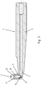
- FIG. 1 shows an electrode for a welding gun, not shown.
- the welding gun includes a further, possibly identical electrode, which is not shown in detail.
- the electrode shown is formed in one piece and comprises an elongated, cylindrical electrode shaft 2 which tapers at one end and has a so-called cap holder 3 in the form of a transversely projecting, conical hollow pin. In the representation of the Figure 1 this hollow pin protrudes upwards. Its diameter is smaller than that of the electrode shaft 2. It is used to hold a welding cap, not shown, which has a conical seat as a counterpart and is placed over the cap holder.
- the electrode shaft 2 has a coolant channel and is connected on the inside to a coolant channel in the cap holder 3, so that on the inside, a cooling fluid can be passed to the cap holder 3, which serves to cool the welding cap. This dissipates the heat generated during welding.
- the cap holder 3 is a one-piece component of the electrode shaft. If the cap holder 3 is worn in the area of its outer cone, the entire electrode shaft 2 and therefore the entire electrode 1 must be replaced.
- the configuration of the electrode according to the invention Figure 2 now provides a multi-part embodiment.
- the electrode 1 according to the invention in turn comprises an essentially cylindrical electrode shaft 2, which tapers at one end and in turn has a cap holder 3 protruding transversely to the longitudinal direction of the electrode shaft 2, onto which a welding cap 4 is placed. From the cap holder 3 is in Figure 2 only one tool contact surface 5 can be seen. A hexagon wrench can be attached here to screw the cap holder 3 into the electrode shaft 2. Details are in Figure 3 recognizable.
- FIG. 3 shows the components of the electrode 1 according to the invention consisting of different copper materials.
- the electrode shaft 2 consists of a highly conductive copper material, for example the material groups Cu-OF, Cu-OFE, Cu-ETP, Cu-HCP, Cu-PLP, Cu -PHC, DLPS-Cu or CuAg01P.
- the most wear-resistant component of the electrode must be the cap holder 3 in addition to the welding cap 4. It can be seen that the cap holder 3 is screwed into the electrode shaft 2 via a screw connection 6. Here, a tight connection is created between a coolant channel 7 in the interior of the electrode shaft 2 and a cooling channel 8 which passes through the entire cap holder 3.
- Figure 4 shows in an enlarged view the cap holder 3 with its threaded portion 9 in the foot area and the subsequent tool contact surface 5, in the form of an external hexagon.
- This is followed by an externally conical peg (cone 10) on which the welding cap, as shown in Figure 5 is shown, can be attached.
- the welding cap 4 shows in the Assembly position that it has a conical opening on its lower side, the taper of the opening mating with the cone 10 of the cap holder 3.
- a free space 11 between the end face of the cone 10 and the deepest part of the conical receptacle 12 prevents the welding cap 4 from sitting on the cap holder 3. In any case, it is a clamp connection.
- cooling fluid flows through the free space 11, so that a larger heat transfer surface is created between the cooling medium and the welding cap 4 in order to enable effective heat dissipation.
- the cone between the cap holder 3 and the welding cap 4 is preferably 1:10.
- the welding cap 4 in Figure 5 has, for example, a height of 22 mm and a diameter of 16 mm.
- the upper half of the welding cap is rounded in a spherical shape and flattened at the tip in a diameter range of approx. 5 mm.
- the lower part of the welding cap adjoins the rounded upper half in a cylindrical shape and serves on the inside to form the conical receptacle 12, as shown in FIG Figure 3 is shown.
Landscapes
- Chemical & Material Sciences (AREA)
- Engineering & Computer Science (AREA)
- Mechanical Engineering (AREA)
- Materials Engineering (AREA)
- Metallurgy (AREA)
- Organic Chemistry (AREA)
- Resistance Welding (AREA)
- Arc Welding In General (AREA)
Description
- Die Erfindung betrifft eine Elektrode für eine Schweißzange umfassend einen Elektrodenschaft mit einer endseitigen Schweißkappe, die lösbar an einem Kappenhalter des Elektrodenschafts befestigt ist.
- Schweißzangen besitzen im Bereich der Elektroden einen zumindest zweiteiligen Aufbau. Die so genannte Schweißkappe ist dasjenige Bauteil, das beim Schweißprozess mit den zu verschweißenden Bauteilen in Kontakt kommt. Die Schweißkappen unterliegen thermischen und mechanischen Beanspruchungen, die durch den Schweißprozess verursacht werden. Als Folge der dadurch auftretenden plastischen Verformung und Erweichung werden die Schweißkappen in regelmäßigen Abständen nachgearbeitet und nach Erreichen der Verschleißgrenze ausgetauscht.
- Die Schweißkappen werden üblicherweise auf einen konischen Zapfen gesteckt. Der Winkel des Konus ist so gewählt, dass es zu einer Selbsthemmung kommt, so dass die Kappen nicht herunter fallen. Zudem werden sie während des Schweißprozesses immer in Längsrichtung des Konus belastet, so dass die Schweißkappen fest und dicht aufsitzen. Die Dichtheit im Bereich des Konus ist wichtig, da die Schweißkappe von innen mit Wasser gekühlt wird. Das Wasser wird über den konischen Kappenhalter am Elektrodenschaft zugeführt.
- Zum Stand der Technik ist auf die
WO 2010/146702 A1 hinzuweisen. Die Druckschrift offenbart eine Elektrode für eine Schweißzange mit einem Elektrodenschaft mit einer endseitigen Schweißkappe, die lösbar an einem Kappenhalter des Elektrodenschafts befestigt ist. Der Kappenhalter und die Schweißkappe bestehen aus einem Kupferwerkstoff, wobei der Kupferwerkstoff des Kappenhalters eine Festigkeit und eine Härte besitzt, wobei die jeweiligen Werte größer sind als die Festigkeit und Härte des Kupferwerkstoffes der Schweißkappe. - Zum Stand der Technik ist ferner auf die
JP H07 195180 A - Die
FR 2 682 626 A1 - Ferner sind zum Stand der Technik die
US 7,022,934 B1 sowie dieWO 2010/143294 A1 zu nennen, die weitere Elektroden für Schweißzangen und deren konstruktiven Aufbau beschreiben. - Es hat sich gezeigt, dass der als Passsitz ausgebildete Konus bei einem Wechsel der Schweißkappen verschleißt. Dies ist darauf zurückzuführen, dass die Elektrodenkappen eine Härte von 140 HBW2,5/62,5 bis 170 HBW2,5/62,5 besitzen, während die Elektrodenschäfte, die in der Regel aus der Legierung CuCr1Zr besteht, grundsätzlich Härten zwischen 130 HBW2,5/62,5 bis 160 HBW2,5/62,5 haben. Dadurch tritt beim Wechsel der Elektrodenkappen abrasiver Verschleiß nicht an der Schweißkappe, sondern an dem Kappenhalter auf. Die Schweißkappen sitzen zudem so fest, dass sie mit einer Vorrichtung abgedreht werden müssen, was zu Verschleißspuren in Umfangsrichtung des Konus am Kappenhalter führt. Wenn trotz dieses Verschleißes eine neue Elektrodenkappe aufgesetzt wird, kann es zu Undichtigkeiten kommen mit der Folge, dass der gesamte Elektrodenschaft und mithin die gesamte Elektrode auszutauschen ist.
- Der Erfindung liegt die Aufgabe zugrunde, eine Elektrode für eine Schweißzange aufzuzeigen, welche gegenüber bekannten Elektroden weniger anfällig für Verschleiß ist und eine höhere Standzeit besitzt.
- Diese Aufgabe ist bei einer Elektrode mit den Merkmalen des Patentanspruchs 1 gelöst.
- Vorteilhafte Weiterbildungen der Erfindung sind Gegenstand der Unteransprüche.
- Die erfindungsgemäße Elektrode für eine Schweißzange umfasst einen Elektrodenschaft mit einer endseitigen Schweißkappe, die lösbar an einem Kappenhalter des Elektrodenschafts befestigt ist. Der Kappenhalter und die Schweißkappe bestehen aus einem Kupferwerkstoff, wobei der Kupferwerkstoff des Kappenhalters eine größere Festigkeit aufweist als der Kupferwerkstoff der Schweißkappe. Die unterschiedlichen Festigkeiten der Kupferwerkstoffe führen dazu, dass bei einem Wechsel der Schweißkappe nicht der Kappenhalter beschädigt wird, sondern die Schweißkappe. Die Festigkeiten verhalten sich mithin umgekehrt wie im Stand der Technik.
- Die Erfindung hat zudem den Vorteil, dass nicht der gesamte Elektrodenschaft eine größere Festigkeit aufweisen muss als die Schweißkappe, sondern lediglich der Kappenhalter.
- Wesentlich bei der Erfindung ist, dass derjenige Bereich, der im Bereich des Elektrodenschafts verschleißen kann, nämlich der Kappenhalter, im Rahmen des technisch Möglichen und insbesondere unter Beibehaltung einer möglichst hohen Leitfähigkeit einen hinreichenden Widerstand gegen mechanische Einflüsse besitzt. Dies ist durch die Wahl einer geeigneten Kupferwerkstoff-Paarung möglich
- Der Kupferwerkstoff des Kappenhalters weist nicht nur eine größere Festigkeit auf als der Kupferwerkstoff der Schweißkappe, sondern zudem auch noch eine größere Härte. Wenn F1 und H1 für die Festigkeit und Härte des Kupferwerkstoffes des Kappenhalters stehen und F2 und H2 für die Festigkeit und Härte des Kupferwerkstoffes der Schweißkappe sollen folgende Bedingungen erfüllt sein:
- F1 > F2
- und H1 > H2.
- Die Härte der Schweißkappe liegt in einem Bereich von 160 HBW2,5/62,5 bis 180 HBW2,5/62,5. Die Härte des Kappenhalters soll mithin im Mittel in einem größeren Härtebereich liegen. Sie beträgt 180 HBW2,5/62,5 bis 220 HBW2,5/187,5. Insbesondere liegt die Härte des Kappenhalters über 190 HBW. Durch einen Härteunterschied von 10 HBW bis 30 HBW wird sichergestellt, dass beim Wechsel der Verschleißkappe die mechanische Beanspruchung maßgeblich auf Seiten der Schweißkappe erfolgt und nicht zu Beschädigungen der Oberfläche des Kappenhalters führt.
- Für die Werkstoffauswahl des Elektrodenschafts kommen sowohl hochleitfähige als auch hochfeste Kupferwerkstoffe in Frage. Eine Rolle für die Werkstoffwahl spielt hierbei, ob der Elektrodenschaft auf Druck beansprucht wird, wie ein gerader Elektrodenschaft, oder ob der Elektrodenschaft gebogen ist und mithin auf Biegung beansprucht wird. Bei der Schweißkappe ist zu beachten, dass eine hohe Wärmebeanspruchung erfolgt, so dass die Schweißkappe aus einer aushärtbaren und damit warmfesten Kupferlegierung bestehen muss. Bei den aushärtbaren Werkstoffen ist allerdings die spezifische elektrische Leitfähigkeit niedriger und damit der Stromverbrauch höher als bei reinen Kupferqualitäten. Die spezifische Leitfähigkeit beträgt bei CuCrZr 45 MS/m bis 50 MS/m. Bei CuNiSiCr beträgt die spezifische elektrische Leitfähigkeit ca. 25 MS/m bis 30 MS/m.
- Eine Temperaturbeanspruchung liegt im hinteren Teil des Elektrodenschafts so gut wie nicht vor. Die mechanische Beanspruchung im hinteren Teil kann je nach konstruktiver Ausführung gering bis hoch sein. Typische Anpresskräfte bei Schweißvorgängen liegen in einer Größenordnung von 4,5 kN. Die Druckbeanspruchung bei geraden Elektrodenschäften beträgt oftmals nur ca. 5 MPa, wobei ein Außendurchmesser eines kreisrunden Elektrodenschafts von 35 mm und ein Innendurchmesser von 12 mm angenommen worden ist.
- Der Elektrodenschaft besteht aus dem hochfesten Kupferwerkstoff CuNiSi mit 0,5 - 4,0 Gew.-% Nickel (Ni) und 0,1 - 2,0 Gew.-% Silizium (Si).
- Der Kappenhalter besteht vorzugsweise aus CuNiSi mit 0,5 - 4,0 Gew.-% Nickel (Ni) und 0,1 - 2,0 Gew.-% Silizium (Si).
- Alle Angaben verstehen sich zuzüglich erschmelzungsbedingter Verunreinigungen im Rahmen der technisch üblichen Reinheiten.
- Bei einer Werkstoffkombination aus verschleißbeständigem Kappenhalter und einem Elektrodenschaft kann die Festigkeit des Elektrodenschafts auch durch reine Kaltverformung und/oder durch eine Mischkristallverfestigung und/oder durch eine Aushärtung sowie eine Kombination der drei Verfahren erzielt werden.
- Mit der Erfindung wird insbesondere ein Elektrodenschaft aus einem verschleißbeständigen Kupferwerkstoff bereitgestellt, der vorzugsweise eine hohe Härte besitzt. Dies gilt insbesondere für den Kappenhalter, der materialeinheitlich einstückiges Bestandteil des Elektrodenschafts sein kann oder als separates Bauteil mit dem Elektrodenschaft verbunden ist. Insbesondere besteht der Kappenhalter aus einem verschleißbeständigen Werkstoff, insbesondere einem solchen mit höherer Festigkeit und/oder Härte als der Elektrodenschaft selbst.
- Aus diesem Grund können die vorgenannten Werkstoffe je nach Anwendungsfall zusätzlich noch ein oder mehrere Legierungskomponenten aufweisen, ausgewählt aus der nachfolgenden Gruppe. Sofern die in der nachfolgend genannten Gruppe enthaltenen Legierungskomponenten bereits Bestandteil der oben genannten Legierungen sind, gelten die ursprünglich genannten Legierungsbereiche. Die in Frage kommenden Legierungskomponenten sind in den gegebenen Grenzen:
Phosphor (P) 0,001 - 0,05 Gew.-% Mangan (Mn) 0,01 - 0,8 Gew.-% Chrom (Cr) 0,01 - 0,5 Gew.-% Aluminium (Al) 0,01 - 0,5 Gew.-% Magnesium (Mg) 0,01 - 0,5 Gew.-% Eisen (Fe) 0,01 - 0,5 Gew.-% Zink (Zn) 0,01 - 2,5 Gew.-% Zirkon (Zr) 0,01 - 0,5 Gew.-% Zinn (Sn) 0,01 - 2,5 Gew.-% Silber (Ag) 0,01 - 0,5 Gew.-% - Zu den zusätzlichen Legierungsbestandteilen ist anzumerken, dass Phosphor als Desoxidationsmittel dient, das den in der Schmelze gelösten freien Sauerstoff an sich bindet und somit Gasblasen (auch Wasserstoffkrankheit) und Oxidation von Legierungsbestandteilen verhindert. Des Weiteren wird Phosphor zugegeben, um die Fließeigenschaften der Kupferlegierung beim Gießen zu verbessern.
- Mangan verfeinert das Korn und verbessert in der Kombination mit Schwefel die Zerspanbarkeit bzw. verhindert eine Phasenbildung des Schwefels mit den Legierungselementen des entsprechenden Legierungstyps. Mangan dient ebenfalls als Desoxidationsmittel.
- Aluminium erhöht die Härte und Dehngrenze ohne Verminderung der Zähigkeit. Aluminium ist ein Element, das die Festigkeit, Bearbeitbarkeit und Verschleißbeständigkeit sowie die Oxidationsresistenz bei hohen Temperaturen verbessert.
- Chrom und Magnesium dienen zur Verbesserung der Oxidationsresistenz bei hohen Temperaturen. Besonders gute Ergebnisse werden hierbei erzielt, wenn diese mit Aluminium gemischt werden, um einen Synergieeffekt zu erzielen.
- Eisen erhöht die Korrosionsbeständigkeit und bildet zusammen mit Phosphor Eisenphosphid-Phasen zur Härtesteigerung.
- Zirkon verbessert die Warmumformbarkeit.
- Zinn steigert die Mischkristallverfestigung.
- Silber erhöht die Rekristallisationstemperatur ohne die Leitfähigkeit nennswert zu erniedrigen.
- Die Mehrteiligkeit der Elektrode kann in konstruktiver Hinsicht durch eine lösbare Verbindung zwischen dem Kappenhalter und dem Elektrodenschaft realisiert werden. Die Schweißkappe selbst bleibt ein austauschbares Teil. Die Verbindung zwischen dem Kappenhalter und der Schweißkappe ist mithin vorzugsweise immer eine lösbare Verbindung. Da es jedoch zwei mögliche Schnittstellen für lösbare Verbindungen gibt, nämlich einmal zwischen dem Kappenhalter und der Schweißkappe sowie zwischen dem Kappenhalter und dem Elektrodenschaft, ist es möglich, bei Bedarf den Kappenhalter zusammen mit der Schweißkappe auszutauschen, falls sich die Schweißkappe aus bestimmten Gründen nicht entfernen lässt oder falls der Kappenhalter verschlissen sein sollte.
- Die Verbindung zwischen dem Kappenhalter und dem Elektrodenschaft ist insbesondere eine Schraubverbindung. Schraubverbindungen lassen sich einfach und kostengünstig realisieren und ermöglichen bei entsprechenden Anzugsmomenten einen ausreichend festen Sitz für die Beanspruchungsart. Zudem können Schraubverbindungen die notwendige Dichtigkeit herstellen.
- Zudem kann in der Schraubenverbindung eine Dichtscheibe, vorzugsweise aus Kupfer oder einer Kupferlegierung, eingebracht werden um die Dichtheit der Verbindung sicher zu gewährleisten. Die Dichtscheibe kann aus den vorher aufgeführten Kupferwerkstoffen bzw. Kupferlegierungen bestehen.
- Der Kappenhalter besitzt in bevorzugter Ausgestaltung an einem Ende einen Gewindeabschnitt für die Schraubverbindung mit dem Elektrodenschaft und an seinem anderen Ende einen Konus als Steckaufnahme für die Schweißkappe. Hierbei sind der Gewindeabschnitt und der Konus fluchtend angeordnet. Die Längsrichtung des Kappenhalters entspricht beim Schweißen der Richtung der Krafteinleitung, so dass der Gewindeabschnitt nicht auf Biegung beansprucht wird. Gleichzeitig wird die Schweißkappe fest gegen den Konus gedrückt und ist dadurch sicher am Konus gehalten.
- Im Kappenhalter befindet sich ein Kühlkanal, der sich in Längsrichtung des Kappenhalters erstreckt. Dadurch kann eine Kühlflüssigkeit an die Schweißkappe herangebracht werden, um die beim Schweißen entstehende Wärme abzuführen.
- Es kann zusätzlich eine Dichtscheibe zwischen dem Kappenhalter und der Schweißkappe und/oder zwischen dem Kappenhalter und dem Elektrodenschaft angeordnet sein, insbesondere wenn es sich um Schraubverbindungen handelt. Die Dichtscheibe kann aus einem Kupferwerkstoff bestehen.
- In alternativer Ausgestaltung ist es möglich, den Kappenhalter unlösbar mit dem Elektrodenschaft zu verbinden. Mögliche Fügeverfahren sind bevorzugt solche mit geringer Wärmeeinbringung. Es kann sich um Hart- oder Weichlötverfahren handeln. Ebenso kommen Strahlschweißverfahren, wie beispielsweise das Laser- und Elektronenstrahlschweißen, in Frage. Auch eine Kombination dieser Verfahren untereinander ist möglich, ebenso wie eine Kombination mittels WIG-Schweißen. Die Austauschbarkeit des Kappenhalters wird aber primär durch eine lösbare Verbindung ermöglicht, so dass hierin die bevorzugte Ausführungsform gesehen wird.
- Die Erfindung wird nachfolgend anhand eines in den Zeichnungen dargestellten Ausführungsbeispiels näher erläutert. Es zeigt:
- Figur 1
- eine Elektrode in konventioneller Bauweise (Stand der Technik);
- Figur 2
- eine erfindungsgemäße Elektrode;
- Figur 3
- einen Längsschnitt durch die Elektrode der
Figur 2 ; - Figur 4
- einen Kappenhalter in perspektivischer Darstellung und
- Figur 5
- eine Schweißkappe in perspektivischer Darstellung.
-
Figur 1 zeigt eine Elektrode für eine nicht näher dargestellte Schweißzange. Die Schweißzange umfasst eine weitere, gegebenenfalls baugleiche Elektrode, die nicht näher dargestellt ist. Die dargestellte Elektrode ist einstückig ausgebildet und umfasst einen langgestreckten, zylindrischen Elektrodenschaft 2, der an einem Ende spitz zuläuft und einen so genannten Kappenhalter 3 in Form eines quer abstehenden, konischen Hohlzapfens aufweist. In der Darstellung derFigur 1 ragt dieser Hohlzapfen nach oben. Sein Durchmesser ist geringer als der des Elektrodenschafts 2. Er dient zur Aufnahme einer nicht näher dargestellten Schweißkappe, die als Gegenstück eine konische Aufnahme besitzt und über den Kappenhalter gestülpt wird. Der Elektrodenschaft 2 besitzt einen Kühlmittelkanal und ist innenseitig mit einem Kühlmittelkanal im Kappenhalter 3 verbunden, so dass innenseitig ein Kühlfluid bis zum Kappenhalter 3 geleitet werden kann, das dazu dient, die Schweißkappe zu kühlen. Dadurch wird die beim Schweißen entstehende Wärme abgeführt. Der Kappenhalter 3 ist materialeinheitlich einstückiges Bestandteil des Elektrodenschafts. Wenn der Kappenhalter 3 im Bereich seines Außenkonus verschlissen ist, muss der gesamte Elektrodenschaft 2 und mithin die gesamte Elektrode 1 ausgetauscht werden. - Die erfindungsgemäße Ausgestaltung der Elektrode gemäß
Figur 2 sieht nunmehr eine mehrteilige Ausführungsform vor. Nachfolgend werden für im Wesentlichen identische Bauteile die bereits inFigur 1 eingeführten Bezugszeichen verwendet. Die erfindungsgemäße Elektrode 1 umfasst wiederum einen im Wesentlichen zylindrischen Elektrodenschaft 2, der sich an einem Ende verjüngt und wiederum einen quer zur Längsrichtung des Elektrodenschafts 2 abstehenden Kappenhalter 3 besitzt, auf den eine Schweißkappe 4 aufgesetzt ist. Von dem Kappenhalter 3 ist inFigur 2 nur eine Werkzeuganlagefläche 5 zu erkennen. Hier kann ein Sechskantschlüssel aufgesetzt werden, um den Kappenhalter 3 in den Elektrodenschaft 2 einzuschrauben. Einzelheiten hierzu sind inFigur 3 erkennbar. -
Figur 3 zeigt die aus unterschiedlichen Kupferwerkstoffen bestehenden Bestandteile der erfindungsgemäßen Elektrode 1. Der Elektrodenschaft 2 besteht bei diesem nicht erfindungsgemäßen Beispiel aus einem hochleitfähigen Kupferwerkstoff, beispielsweise der Werkstoffgruppen Cu-OF, Cu-OFE, Cu-ETP, Cu-HCP, Cu-PLP, Cu-PHC, DLPS-Cu oder CuAg01P. Der verschleißbeständigste Bestandteil der Elektrode muss neben der Schweißkappe 4 der Kappenhalter 3 sein. Es ist zu erkennen, dass der Kappenhalter 3 über eine Schraubverbindung 6 in den Elektrodenschaft 2 geschraubt ist. Hierbei wird eine dichte Verbindung zwischen einem Kühlmittelkanal 7 im Inneren des Elektrodenschafts 2 und einem Kühlkanal 8 geschaffen, der den gesamten Kappenhalter 3 durchsetzt. -
Figur 4 zeigt in vergrößerter Darstellung den Kappenhalter 3 mit seinem Gewindeabschnitt 9 im Fußbereich und die darauf folgende Werkzeuganlagefläche 5, in Form eines Außensechskants. Hierauf schließt sich dann ein außenseitig konischer Zapfen (Konus 10) an, auf den die Schweißkappe, wie sie inFigur 5 dargestellt ist, aufgesteckt werden kann. Die Schweißkappe 4 zeigt in der Zusammenbauposition, dass sie an ihrer unteren Seite eine konische Öffnung aufweist, wobei die Konizität der Öffnung mit dem Konus 10 des Kappenhalters 3 zusammenpasst. Ein Freiraum 11 zwischen der Stirnseite des Konus 10 und dem Tiefsten der konischen Aufnahme 12 verhindert, dass die Schweißkappe 4 auf dem Kappenhalter 3 aufsitzt. Es handelt sich in jedem Fall um eine Klemmverbindung. Zudem wird der Freiraum 11 von Kühlflüssigkeit durchströmt, so dass eine größere Wärmeübertragerfläche zwischen dem Kühlmedium und der Schweißkappe 4 geschaffen wird, um eine effektive Wärmeabfuhr zu ermöglichen. Der Kegel zwischen dem Kappenhalter 3 und der Schweißkappe 4 beträgt vorzugsweise 1 : 10. - Die Schweißkappe 4 in
Figur 5 besitzt beispielsweise eine Höhe von 22 mm und einen Durchmesser von 16 mm. Die Schweißkappe ist in ihrer oberen Hälfte halbkugelförmig gerundet und an der Spitze in einem Durchmesserbereich von ca. 5 mm abgeflacht. Der untere Teil der Schweißkappe schließt sich in zylindrischer Form an die gerundete obere Hälfte an und dient innenseitig zur Ausbildung der konischen Aufnahme 12, wie sie inFigur 3 dargestellt ist. -
- 1 -
- Elektrode
- 2 -
- Elektrodenschaft
- 3 -
- Kappenhalter
- 4 -
- Schweißkappe
- 5 -
- Werkzeugangrifffläche
- 6 -
- Schraubverbindung
- 7 -
- Kühlmittelkanal
- 8 -
- Kühlmittelkanal
- 9 -
- Gewindeabschnitt
- 10 -
- Konus
- 11 -
- Freiraum
- 12 -
- Aufnahme
Claims (8)
- Elektrode für eine Schweißzange umfassend einen Elektrodenschaft (2) mit einer endseitigen Schweißkappe (4), die lösbar an einem Kappenhalter (3) des Elektrodenschafts (1) befestigt ist, wobei der Kappenhalter (3) und die Schweißkappe (4) aus einem Kupferwerkstoff bestehen, wobei der Kupferwerkstoff des Kappenhalters (3) eine Festigkeit F1 und eine Härte H1 besitzt und wobei der Kupferwerkstoff der Schweißkappe (4) eine Festigkeit F2 und eine Härte H2 besitzt, wobei F1 größer F2 ist und wobei H1 größer H2 ist, dadurch gekennzeichnet, dass die Härte H2 der Schweißkappe (4) in einem Bereich von 160 HBW2,5/62,5 bis 180 HBW2,5/62,5 liegt und die Härte H1 des Kappenhalters (3) über 180 HBW2,5/62,5 liegt und bis 220 HBW2,5/187,5 beträgt, wobei der Elektrodenschaft (2) aus dem hochfesten Kupferwerkstoff CuNiSi mit 0,5 - 4,0 Gew.-% Ni und 0,1 - 2,0 Gew.-% Si besteht und wobei der Kappenhalter (3) aus CuNiSi mit 0,5 - 4,0 Gew.-% Ni und 0,1 - 2,0 Gew.-% Si besteht.
- Elektrode nach Anspruch 1, dadurch gekennzeichnet, dass der Werkstoff zusätzlich ein oder mehrere Legierungskomponenten ausgewählt aus der nachfolgenden Gruppe enthalten kann, sofern diese nachfolgend genannten Legierungskomponenten nicht bereits in den zu den vorstehend genannten Werkstoffen enthaltenen Grenzen enthalten sind:
Phosphor (P) 0,001 - 0,05 Gew.-% Mangan (Mn) 0,01 - 0,8 Gew.-% Chrom (Cr) 0,01 - 0,5 Gew.-% Aluminium (Al) 0,01 - 0,5 Gew.-% Magnesium (Mg) 0,01 - 0,5 Gew.-% Eisen (Fe) 0,01 - 0,5 Gew.-% Zink (Zn) 0,01 - 2,5 Gew.-% Zirkon (Zr) 0,01 - 0,5 Gew.-% Zinn (Sn) 0,01 - 2,5 Gew.-% Silber (Ag) 0,01 - 0,5 Gew.-% - Elektrode nach Anspruch 1 oder 2, dadurch gekennzeichnet, dass der Kappenhalter (3) lösbar mit dem Elektrodenschaft (1) verbunden ist.
- Elektrode nach einem der Ansprüche 1 bis 3, dadurch gekennzeichnet, dass der Kappenhalter (3) über eine Schraubverbindung (6) mit dem Elektrodenschaft (1) verbunden ist.
- Elektrode nach einem der Ansprüche 1 bis 4, dadurch gekennzeichnet, dass der Kappenhalter (3) an einem Ende einen Gewindeabschnitt (9) für die Schraubverbindung (6) mit dem Elektrodenschaft (1) aufweist und an seinem anderen Ende einen Konus (10) als Steckaufnahme für die Schweißkappe (4), wobei der Gewindeabschnitt (9) und der Konus (10) fluchtend angeordnet sind.
- Elektrode nach Anspruch 5, dadurch gekennzeichnet, dass im Kappenhalter (3) ein Kühlmittelkanal (8) angeordnet ist, der sich in Längsrichtung des Kappenhalters (3) erstreckt.
- Elektrode nach einem der Ansprüche 1 bis 6, dadurch gekennzeichnet, dass eine Dichtscheibe zwischen dem Kappenhalter (3) und der Schweißkappe (4) und/oder zwischen dem Kappenhalter (3) und dem Elektrodenschaft (1) angeordnet ist.
- Elektrode nach Anspruch 1 oder 2, dadurch gekennzeichnet, dass der Kappenhalter (3) unlösbar mit dem Elektrodenschaft (1) verbunden ist.
Applications Claiming Priority (2)
| Application Number | Priority Date | Filing Date | Title |
|---|---|---|---|
| DE102012019555.9A DE102012019555A1 (de) | 2012-10-05 | 2012-10-05 | Elektrode für eine Schweißzange |
| PCT/DE2013/000563 WO2014053117A2 (de) | 2012-10-05 | 2013-10-02 | Elektrode für eine schweisszange |
Publications (3)
| Publication Number | Publication Date |
|---|---|
| EP2903778A2 EP2903778A2 (de) | 2015-08-12 |
| EP2903778B1 true EP2903778B1 (de) | 2020-07-08 |
| EP2903778B8 EP2903778B8 (de) | 2020-08-19 |
Family
ID=49758954
Family Applications (1)
| Application Number | Title | Priority Date | Filing Date |
|---|---|---|---|
| EP13802865.9A Active EP2903778B8 (de) | 2012-10-05 | 2013-10-02 | Elektrode für eine schweisszange |
Country Status (5)
| Country | Link |
|---|---|
| US (1) | US20150251270A1 (de) |
| EP (1) | EP2903778B8 (de) |
| DE (1) | DE102012019555A1 (de) |
| ES (1) | ES2821834T3 (de) |
| WO (1) | WO2014053117A2 (de) |
Families Citing this family (7)
| Publication number | Priority date | Publication date | Assignee | Title |
|---|---|---|---|---|
| DE102015220970A1 (de) * | 2015-10-27 | 2017-04-27 | Volkswagen Aktiengesellschaft | Schweißelektrode, Widerstandsschweißnietanlage, Widerstandsschweißnietsystem und Widerstandsschweißnietverfahren |
| DE102016208026A1 (de) * | 2016-05-10 | 2017-11-16 | Volkswagen Aktiengesellschaft | Schweißelektrode, Verfahren zum Widerstandspunktschweißen und Kraftfahrzeug |
| KR101921594B1 (ko) * | 2017-03-30 | 2018-11-26 | 광명산업(주) | 스폿 가압력 측정장치 |
| KR102192145B1 (ko) * | 2019-01-11 | 2020-12-16 | 변지상 | 크롬을 함유하지 않는 스포트 캡 팁 전극용 동합금조성물 및 이를 이용하여 제조된 스포트 캡 팁 전극 |
| CN110218903B (zh) * | 2019-07-02 | 2020-07-14 | 西峡龙成特种材料有限公司 | 一种esp连铸结晶器窄面铜板母材及其加工方法、esp连铸结晶器窄面铜板 |
| WO2021165983A1 (en) * | 2020-02-21 | 2021-08-26 | Sumit Dhody | Electrode holder |
| CN111778427B (zh) * | 2020-06-16 | 2021-09-07 | 陕西斯瑞新材料股份有限公司 | 一种电连接器用CuNiSi系合金丝材的制备方法 |
Family Cites Families (9)
| Publication number | Priority date | Publication date | Assignee | Title |
|---|---|---|---|---|
| FR2682626A1 (fr) * | 1991-10-18 | 1993-04-23 | Damien France Production Sarl | Electrode pour soudage par points. |
| JPH07195180A (ja) * | 1993-12-31 | 1995-08-01 | Kiyokutoo:Kk | 抵抗溶接ガンにおける電極チップ嵌合部の構造 |
| DE10156925A1 (de) * | 2001-11-21 | 2003-05-28 | Km Europa Metal Ag | Aushärtbare Kupferlegierung als Werkstoff zur Herstellung von Giessformen |
| US7022934B1 (en) * | 2003-06-10 | 2006-04-04 | Honda Giken Kogyo Kabushiki Kaisha | Connecting adapter for weld electrode |
| JP3867982B2 (ja) * | 2004-04-22 | 2007-01-17 | 株式会社エスエムケイ | 溶接用曲り電極 |
| US20100252536A1 (en) * | 2009-04-06 | 2010-10-07 | Ascend Enterprises, Inc. | Contact tip for an electrode of a resistance welder |
| WO2010143294A1 (ja) * | 2009-06-12 | 2010-12-16 | 新光機器株式会社 | スポット溶接機の電極部 |
| WO2010146702A1 (ja) * | 2009-06-19 | 2010-12-23 | P&C株式会社 | スポット溶接機の電極部 |
| US8785807B2 (en) * | 2011-03-17 | 2014-07-22 | GM Global Technology Operations LLC | Welding electrode and method of forming a resistance spot weld joint |
-
2012
- 2012-10-05 DE DE102012019555.9A patent/DE102012019555A1/de not_active Withdrawn
-
2013
- 2013-10-02 EP EP13802865.9A patent/EP2903778B8/de active Active
- 2013-10-02 WO PCT/DE2013/000563 patent/WO2014053117A2/de not_active Ceased
- 2013-10-02 ES ES13802865T patent/ES2821834T3/es active Active
- 2013-10-02 US US14/433,559 patent/US20150251270A1/en not_active Abandoned
Non-Patent Citations (1)
| Title |
|---|
| None * |
Also Published As
| Publication number | Publication date |
|---|---|
| EP2903778A2 (de) | 2015-08-12 |
| EP2903778B8 (de) | 2020-08-19 |
| US20150251270A1 (en) | 2015-09-10 |
| ES2821834T3 (es) | 2021-04-27 |
| WO2014053117A3 (de) | 2014-05-30 |
| DE102012019555A1 (de) | 2014-04-10 |
| WO2014053117A2 (de) | 2014-04-10 |
Similar Documents
| Publication | Publication Date | Title |
|---|---|---|
| DE102012019555A1 (de) | Elektrode für eine Schweißzange | |
| EP2700727A1 (de) | Al-Gusslegierung | |
| EP2409862B2 (de) | Querlenker | |
| EP3004413B1 (de) | Mine für kugelschreiber und verwendung | |
| EP2662168A1 (de) | Sägeblatt mit einem pulvermetallurgisch hergestellten Schneidteil | |
| EP3088084A1 (de) | Hartkörper als rasterpanzerung für eine rollenpresse, verfahren zu dessen herstellung, und rolle für eine rollenpresse | |
| DE112018007461T5 (de) | Punktschweisselektrodenkappe | |
| DE112008002853B4 (de) | Gerippte Widerstandspunktschweißelektrode | |
| DE102009025197B4 (de) | Verfahren zur Herstellung von Verbundmetall-Halbzeugen | |
| DE1967005B2 (de) | Verfahren zum herstellen eines nickel-chrom-kobalt-werkstoffs | |
| DE10206597A1 (de) | Aushärtbare Kupferlegierung | |
| DE602005001743T2 (de) | Zündkerze | |
| DE202015102269U1 (de) | Hochleistungs-Aluminium-Punktschweisselektrode | |
| DE102013014502A1 (de) | Kupferlegierung | |
| EP2431112B1 (de) | Druckgusskolben | |
| DE3605763C2 (de) | ||
| WO2013144043A1 (de) | Werkstück und ein verfahren zur herstellung eines werkstückes | |
| EP4452550A1 (de) | PUNKTSCHWEIß-ELEKTRODENKAPPE | |
| WO2013139484A1 (de) | Plasmaelektrode für einen plasma-lichtbogenbrenner mit auswechselbarer elektrodenspitze | |
| DE2808392A1 (de) | Elektrode bzw. elektrodenkappe fuer die elektrische widerstandsschweissung | |
| DE102016006249A1 (de) | Schweißelektrode zum Widerstandspunktschweißen | |
| DE102014202435A1 (de) | Modular ausgebildeter Schweißelektrodenhalter | |
| WO2015027976A2 (de) | Kupferlegierung | |
| DE3834186A1 (de) | Legierung, insbesondere zur verwendung zur herstellung von brillengestellen | |
| DE102007005536A1 (de) | Verfahren zur Herstellung einer Elektrode, insbesondere einer Elektrodenkappe zum Widerstandspunktschweißen |
Legal Events
| Date | Code | Title | Description |
|---|---|---|---|
| PUAI | Public reference made under article 153(3) epc to a published international application that has entered the european phase |
Free format text: ORIGINAL CODE: 0009012 |
|
| 17P | Request for examination filed |
Effective date: 20150430 |
|
| AK | Designated contracting states |
Kind code of ref document: A2 Designated state(s): AL AT BE BG CH CY CZ DE DK EE ES FI FR GB GR HR HU IE IS IT LI LT LU LV MC MK MT NL NO PL PT RO RS SE SI SK SM TR |
|
| AX | Request for extension of the european patent |
Extension state: BA ME |
|
| DAX | Request for extension of the european patent (deleted) | ||
| STAA | Information on the status of an ep patent application or granted ep patent |
Free format text: STATUS: EXAMINATION IS IN PROGRESS |
|
| 17Q | First examination report despatched |
Effective date: 20181203 |
|
| GRAP | Despatch of communication of intention to grant a patent |
Free format text: ORIGINAL CODE: EPIDOSNIGR1 |
|
| STAA | Information on the status of an ep patent application or granted ep patent |
Free format text: STATUS: GRANT OF PATENT IS INTENDED |
|
| INTG | Intention to grant announced |
Effective date: 20200325 |
|
| GRAS | Grant fee paid |
Free format text: ORIGINAL CODE: EPIDOSNIGR3 |
|
| GRAJ | Information related to disapproval of communication of intention to grant by the applicant or resumption of examination proceedings by the epo deleted |
Free format text: ORIGINAL CODE: EPIDOSDIGR1 |
|
| GRAL | Information related to payment of fee for publishing/printing deleted |
Free format text: ORIGINAL CODE: EPIDOSDIGR3 |
|
| STAA | Information on the status of an ep patent application or granted ep patent |
Free format text: STATUS: EXAMINATION IS IN PROGRESS |
|
| STAA | Information on the status of an ep patent application or granted ep patent |
Free format text: STATUS: GRANT OF PATENT IS INTENDED |
|
| GRAA | (expected) grant |
Free format text: ORIGINAL CODE: 0009210 |
|
| STAA | Information on the status of an ep patent application or granted ep patent |
Free format text: STATUS: THE PATENT HAS BEEN GRANTED |
|
| INTC | Intention to grant announced (deleted) | ||
| AK | Designated contracting states |
Kind code of ref document: B1 Designated state(s): AL AT BE BG CH CY CZ DE DK EE ES FI FR GB GR HR HU IE IS IT LI LT LU LV MC MK MT NL NO PL PT RO RS SE SI SK SM TR |
|
| REG | Reference to a national code |
Ref country code: GB Ref legal event code: FG4D Free format text: NOT ENGLISH |
|
| REG | Reference to a national code |
Ref country code: CH Ref legal event code: EP Ref country code: AT Ref legal event code: REF Ref document number: 1287929 Country of ref document: AT Kind code of ref document: T Effective date: 20200715 |
|
| REG | Reference to a national code |
Ref country code: DE Ref legal event code: R096 Ref document number: 502013014902 Country of ref document: DE |
|
| REG | Reference to a national code |
Ref country code: CH Ref legal event code: PK Free format text: BERICHTIGUNG B8 |
|
| RAP2 | Party data changed (patent owner data changed or rights of a patent transferred) |
Owner name: KME GERMANY GMBH |
|
| REG | Reference to a national code |
Ref country code: IE Ref legal event code: FG4D Free format text: LANGUAGE OF EP DOCUMENT: GERMAN |
|
| REG | Reference to a national code |
Ref country code: DE Ref legal event code: R081 Ref document number: 502013014902 Country of ref document: DE Owner name: CUNOVA GMBH, DE Free format text: FORMER OWNER: KME GERMANY GMBH & CO. KG, 49074 OSNABRUECK, DE Ref country code: DE Ref legal event code: R081 Ref document number: 502013014902 Country of ref document: DE Owner name: KME SPECIAL PRODUCTS & SOLUTIONS GMBH, DE Free format text: FORMER OWNER: KME GERMANY GMBH & CO. KG, 49074 OSNABRUECK, DE Ref country code: DE Ref legal event code: R081 Ref document number: 502013014902 Country of ref document: DE Owner name: KME SPECIAL PRODUCTS GMBH & CO. KG, DE Free format text: FORMER OWNER: KME GERMANY GMBH & CO. KG, 49074 OSNABRUECK, DE |
|
| RAP2 | Party data changed (patent owner data changed or rights of a patent transferred) |
Owner name: KME SPECIAL PRODUCTS GMBH |
|
| REG | Reference to a national code |
Ref country code: LT Ref legal event code: MG4D |
|
| REG | Reference to a national code |
Ref country code: NL Ref legal event code: MP Effective date: 20200708 |
|
| REG | Reference to a national code |
Ref country code: SK Ref legal event code: T3 Ref document number: E 35618 Country of ref document: SK |
|
| PG25 | Lapsed in a contracting state [announced via postgrant information from national office to epo] |
Ref country code: PT Free format text: LAPSE BECAUSE OF FAILURE TO SUBMIT A TRANSLATION OF THE DESCRIPTION OR TO PAY THE FEE WITHIN THE PRESCRIBED TIME-LIMIT Effective date: 20201109 Ref country code: HR Free format text: LAPSE BECAUSE OF FAILURE TO SUBMIT A TRANSLATION OF THE DESCRIPTION OR TO PAY THE FEE WITHIN THE PRESCRIBED TIME-LIMIT Effective date: 20200708 Ref country code: BG Free format text: LAPSE BECAUSE OF FAILURE TO SUBMIT A TRANSLATION OF THE DESCRIPTION OR TO PAY THE FEE WITHIN THE PRESCRIBED TIME-LIMIT Effective date: 20201008 Ref country code: GR Free format text: LAPSE BECAUSE OF FAILURE TO SUBMIT A TRANSLATION OF THE DESCRIPTION OR TO PAY THE FEE WITHIN THE PRESCRIBED TIME-LIMIT Effective date: 20201009 Ref country code: LT Free format text: LAPSE BECAUSE OF FAILURE TO SUBMIT A TRANSLATION OF THE DESCRIPTION OR TO PAY THE FEE WITHIN THE PRESCRIBED TIME-LIMIT Effective date: 20200708 Ref country code: FI Free format text: LAPSE BECAUSE OF FAILURE TO SUBMIT A TRANSLATION OF THE DESCRIPTION OR TO PAY THE FEE WITHIN THE PRESCRIBED TIME-LIMIT Effective date: 20200708 Ref country code: SE Free format text: LAPSE BECAUSE OF FAILURE TO SUBMIT A TRANSLATION OF THE DESCRIPTION OR TO PAY THE FEE WITHIN THE PRESCRIBED TIME-LIMIT Effective date: 20200708 Ref country code: NO Free format text: LAPSE BECAUSE OF FAILURE TO SUBMIT A TRANSLATION OF THE DESCRIPTION OR TO PAY THE FEE WITHIN THE PRESCRIBED TIME-LIMIT Effective date: 20201008 |
|
| PG25 | Lapsed in a contracting state [announced via postgrant information from national office to epo] |
Ref country code: RS Free format text: LAPSE BECAUSE OF FAILURE TO SUBMIT A TRANSLATION OF THE DESCRIPTION OR TO PAY THE FEE WITHIN THE PRESCRIBED TIME-LIMIT Effective date: 20200708 Ref country code: LV Free format text: LAPSE BECAUSE OF FAILURE TO SUBMIT A TRANSLATION OF THE DESCRIPTION OR TO PAY THE FEE WITHIN THE PRESCRIBED TIME-LIMIT Effective date: 20200708 Ref country code: IS Free format text: LAPSE BECAUSE OF FAILURE TO SUBMIT A TRANSLATION OF THE DESCRIPTION OR TO PAY THE FEE WITHIN THE PRESCRIBED TIME-LIMIT Effective date: 20201108 |
|
| PG25 | Lapsed in a contracting state [announced via postgrant information from national office to epo] |
Ref country code: NL Free format text: LAPSE BECAUSE OF FAILURE TO SUBMIT A TRANSLATION OF THE DESCRIPTION OR TO PAY THE FEE WITHIN THE PRESCRIBED TIME-LIMIT Effective date: 20200708 |
|
| REG | Reference to a national code |
Ref country code: DE Ref legal event code: R097 Ref document number: 502013014902 Country of ref document: DE |
|
| REG | Reference to a national code |
Ref country code: ES Ref legal event code: FG2A Ref document number: 2821834 Country of ref document: ES Kind code of ref document: T3 Effective date: 20210427 |
|
| PG25 | Lapsed in a contracting state [announced via postgrant information from national office to epo] |
Ref country code: RO Free format text: LAPSE BECAUSE OF FAILURE TO SUBMIT A TRANSLATION OF THE DESCRIPTION OR TO PAY THE FEE WITHIN THE PRESCRIBED TIME-LIMIT Effective date: 20200708 Ref country code: SM Free format text: LAPSE BECAUSE OF FAILURE TO SUBMIT A TRANSLATION OF THE DESCRIPTION OR TO PAY THE FEE WITHIN THE PRESCRIBED TIME-LIMIT Effective date: 20200708 Ref country code: DK Free format text: LAPSE BECAUSE OF FAILURE TO SUBMIT A TRANSLATION OF THE DESCRIPTION OR TO PAY THE FEE WITHIN THE PRESCRIBED TIME-LIMIT Effective date: 20200708 Ref country code: EE Free format text: LAPSE BECAUSE OF FAILURE TO SUBMIT A TRANSLATION OF THE DESCRIPTION OR TO PAY THE FEE WITHIN THE PRESCRIBED TIME-LIMIT Effective date: 20200708 |
|
| PLBE | No opposition filed within time limit |
Free format text: ORIGINAL CODE: 0009261 |
|
| STAA | Information on the status of an ep patent application or granted ep patent |
Free format text: STATUS: NO OPPOSITION FILED WITHIN TIME LIMIT |
|
| PG25 | Lapsed in a contracting state [announced via postgrant information from national office to epo] |
Ref country code: AL Free format text: LAPSE BECAUSE OF FAILURE TO SUBMIT A TRANSLATION OF THE DESCRIPTION OR TO PAY THE FEE WITHIN THE PRESCRIBED TIME-LIMIT Effective date: 20200708 |
|
| REG | Reference to a national code |
Ref country code: CH Ref legal event code: PL |
|
| 26N | No opposition filed |
Effective date: 20210409 |
|
| PG25 | Lapsed in a contracting state [announced via postgrant information from national office to epo] |
Ref country code: LU Free format text: LAPSE BECAUSE OF NON-PAYMENT OF DUE FEES Effective date: 20201002 Ref country code: MC Free format text: LAPSE BECAUSE OF FAILURE TO SUBMIT A TRANSLATION OF THE DESCRIPTION OR TO PAY THE FEE WITHIN THE PRESCRIBED TIME-LIMIT Effective date: 20200708 |
|
| REG | Reference to a national code |
Ref country code: BE Ref legal event code: MM Effective date: 20201031 |
|
| PG25 | Lapsed in a contracting state [announced via postgrant information from national office to epo] |
Ref country code: LI Free format text: LAPSE BECAUSE OF NON-PAYMENT OF DUE FEES Effective date: 20201031 Ref country code: SI Free format text: LAPSE BECAUSE OF FAILURE TO SUBMIT A TRANSLATION OF THE DESCRIPTION OR TO PAY THE FEE WITHIN THE PRESCRIBED TIME-LIMIT Effective date: 20200708 Ref country code: BE Free format text: LAPSE BECAUSE OF NON-PAYMENT OF DUE FEES Effective date: 20201031 Ref country code: CH Free format text: LAPSE BECAUSE OF NON-PAYMENT OF DUE FEES Effective date: 20201031 |
|
| PG25 | Lapsed in a contracting state [announced via postgrant information from national office to epo] |
Ref country code: IE Free format text: LAPSE BECAUSE OF NON-PAYMENT OF DUE FEES Effective date: 20201002 |
|
| REG | Reference to a national code |
Ref country code: DE Ref legal event code: R081 Ref document number: 502013014902 Country of ref document: DE Owner name: CUNOVA GMBH, DE Free format text: FORMER OWNER: KME SPECIAL PRODUCTS GMBH, 49074 OSNABRUECK, DE Ref country code: DE Ref legal event code: R081 Ref document number: 502013014902 Country of ref document: DE Owner name: KME SPECIAL PRODUCTS & SOLUTIONS GMBH, DE Free format text: FORMER OWNER: KME SPECIAL PRODUCTS GMBH, 49074 OSNABRUECK, DE Ref country code: DE Ref legal event code: R081 Ref document number: 502013014902 Country of ref document: DE Owner name: KME SPECIAL PRODUCTS GMBH & CO. KG, DE Free format text: FORMER OWNER: KME SPECIAL PRODUCTS GMBH, 49074 OSNABRUECK, DE |
|
| REG | Reference to a national code |
Ref country code: AT Ref legal event code: MM01 Ref document number: 1287929 Country of ref document: AT Kind code of ref document: T Effective date: 20201002 |
|
| PG25 | Lapsed in a contracting state [announced via postgrant information from national office to epo] |
Ref country code: AT Free format text: LAPSE BECAUSE OF NON-PAYMENT OF DUE FEES Effective date: 20201002 |
|
| REG | Reference to a national code |
Ref country code: GB Ref legal event code: 732E Free format text: REGISTERED BETWEEN 20220203 AND 20220209 |
|
| PG25 | Lapsed in a contracting state [announced via postgrant information from national office to epo] |
Ref country code: TR Free format text: LAPSE BECAUSE OF FAILURE TO SUBMIT A TRANSLATION OF THE DESCRIPTION OR TO PAY THE FEE WITHIN THE PRESCRIBED TIME-LIMIT Effective date: 20200708 Ref country code: MT Free format text: LAPSE BECAUSE OF FAILURE TO SUBMIT A TRANSLATION OF THE DESCRIPTION OR TO PAY THE FEE WITHIN THE PRESCRIBED TIME-LIMIT Effective date: 20200708 Ref country code: CY Free format text: LAPSE BECAUSE OF FAILURE TO SUBMIT A TRANSLATION OF THE DESCRIPTION OR TO PAY THE FEE WITHIN THE PRESCRIBED TIME-LIMIT Effective date: 20200708 |
|
| PG25 | Lapsed in a contracting state [announced via postgrant information from national office to epo] |
Ref country code: MK Free format text: LAPSE BECAUSE OF FAILURE TO SUBMIT A TRANSLATION OF THE DESCRIPTION OR TO PAY THE FEE WITHIN THE PRESCRIBED TIME-LIMIT Effective date: 20200708 |
|
| REG | Reference to a national code |
Ref country code: DE Ref legal event code: R081 Ref document number: 502013014902 Country of ref document: DE Owner name: CUNOVA GMBH, DE Free format text: FORMER OWNER: KME SPECIAL PRODUCTS GMBH & CO. KG, 49074 OSNABRUECK, DE Ref country code: DE Ref legal event code: R081 Ref document number: 502013014902 Country of ref document: DE Owner name: KME SPECIAL PRODUCTS & SOLUTIONS GMBH, DE Free format text: FORMER OWNER: KME SPECIAL PRODUCTS GMBH & CO. KG, 49074 OSNABRUECK, DE |
|
| REG | Reference to a national code |
Ref country code: DE Ref legal event code: R081 Ref document number: 502013014902 Country of ref document: DE Owner name: CUNOVA GMBH, DE Free format text: FORMER OWNER: KME SPECIAL PRODUCTS & SOLUTIONS GMBH, 49074 OSNABRUECK, DE |
|
| REG | Reference to a national code |
Ref country code: SK Ref legal event code: TC4A Ref document number: E 35618 Country of ref document: SK Owner name: KME SPECIAL PRODUCTS GMBH & CO. KG, OSNABRUECK, DE Effective date: 20241122 Ref country code: SK Ref legal event code: PC4A Ref document number: E 35618 Country of ref document: SK Owner name: CUNOVA GMBH, OSNABRUECK, DE Free format text: FORMER OWNER: KME SPECIAL PRODUCTS GMBH & CO. KG, OSNABRUECK, DE Effective date: 20241122 Ref country code: SK Ref legal event code: PC4A Ref document number: E 35618 Country of ref document: SK Owner name: BLITZ F19-906 GMBH & CO. KG, FRANKFURT AM MAIN, DE Free format text: FORMER OWNER: KME SPECIAL PRODUCTS GMBH, OSNABRUECK, DE Effective date: 20241122 |
|
| PGFP | Annual fee paid to national office [announced via postgrant information from national office to epo] |
Ref country code: PL Payment date: 20250922 Year of fee payment: 13 |
|
| PGFP | Annual fee paid to national office [announced via postgrant information from national office to epo] |
Ref country code: CZ Payment date: 20250926 Year of fee payment: 13 |
|
| PGFP | Annual fee paid to national office [announced via postgrant information from national office to epo] |
Ref country code: SK Payment date: 20250919 Year of fee payment: 13 |
|
| PGFP | Annual fee paid to national office [announced via postgrant information from national office to epo] |
Ref country code: DE Payment date: 20251028 Year of fee payment: 13 |
|
| PGFP | Annual fee paid to national office [announced via postgrant information from national office to epo] |
Ref country code: GB Payment date: 20251023 Year of fee payment: 13 |
|
| PGFP | Annual fee paid to national office [announced via postgrant information from national office to epo] |
Ref country code: IT Payment date: 20251022 Year of fee payment: 13 |
|
| PGFP | Annual fee paid to national office [announced via postgrant information from national office to epo] |
Ref country code: FR Payment date: 20251027 Year of fee payment: 13 |
|
| PGFP | Annual fee paid to national office [announced via postgrant information from national office to epo] |
Ref country code: ES Payment date: 20251118 Year of fee payment: 13 |