EP2902894B1 - Anzeigesteuerungsverfahren, computerprogramm, anzeigesteuerungsvorrichtung und bildanzeigesystem - Google Patents
Anzeigesteuerungsverfahren, computerprogramm, anzeigesteuerungsvorrichtung und bildanzeigesystem Download PDFInfo
- Publication number
- EP2902894B1 EP2902894B1 EP13833901.5A EP13833901A EP2902894B1 EP 2902894 B1 EP2902894 B1 EP 2902894B1 EP 13833901 A EP13833901 A EP 13833901A EP 2902894 B1 EP2902894 B1 EP 2902894B1
- Authority
- EP
- European Patent Office
- Prior art keywords
- area
- display
- pointer
- display area
- screen
- Prior art date
- Legal status (The legal status is an assumption and is not a legal conclusion. Google has not performed a legal analysis and makes no representation as to the accuracy of the status listed.)
- Active
Links
- 238000000034 method Methods 0.000 title claims description 35
- 238000004590 computer program Methods 0.000 title claims description 11
- 238000010586 diagram Methods 0.000 description 39
- 238000004364 calculation method Methods 0.000 description 5
- 238000012544 monitoring process Methods 0.000 description 4
- 239000003086 colorant Substances 0.000 description 2
- 238000002591 computed tomography Methods 0.000 description 2
- 238000005516 engineering process Methods 0.000 description 2
- 238000009434 installation Methods 0.000 description 2
- 238000013341 scale-up Methods 0.000 description 2
- 238000004458 analytical method Methods 0.000 description 1
- 230000001419 dependent effect Effects 0.000 description 1
- 230000000694 effects Effects 0.000 description 1
- 238000012423 maintenance Methods 0.000 description 1
- 238000003908 quality control method Methods 0.000 description 1
Images


Classifications
-
- G—PHYSICS
- G06—COMPUTING; CALCULATING OR COUNTING
- G06F—ELECTRIC DIGITAL DATA PROCESSING
- G06F3/00—Input arrangements for transferring data to be processed into a form capable of being handled by the computer; Output arrangements for transferring data from processing unit to output unit, e.g. interface arrangements
- G06F3/01—Input arrangements or combined input and output arrangements for interaction between user and computer
- G06F3/048—Interaction techniques based on graphical user interfaces [GUI]
- G06F3/0481—Interaction techniques based on graphical user interfaces [GUI] based on specific properties of the displayed interaction object or a metaphor-based environment, e.g. interaction with desktop elements like windows or icons, or assisted by a cursor's changing behaviour or appearance
- G06F3/04812—Interaction techniques based on cursor appearance or behaviour, e.g. being affected by the presence of displayed objects
-
- G—PHYSICS
- G06—COMPUTING; CALCULATING OR COUNTING
- G06F—ELECTRIC DIGITAL DATA PROCESSING
- G06F3/00—Input arrangements for transferring data to be processed into a form capable of being handled by the computer; Output arrangements for transferring data from processing unit to output unit, e.g. interface arrangements
- G06F3/01—Input arrangements or combined input and output arrangements for interaction between user and computer
- G06F3/048—Interaction techniques based on graphical user interfaces [GUI]
- G06F3/0481—Interaction techniques based on graphical user interfaces [GUI] based on specific properties of the displayed interaction object or a metaphor-based environment, e.g. interaction with desktop elements like windows or icons, or assisted by a cursor's changing behaviour or appearance
-
- H—ELECTRICITY
- H04—ELECTRIC COMMUNICATION TECHNIQUE
- H04N—PICTORIAL COMMUNICATION, e.g. TELEVISION
- H04N5/00—Details of television systems
- H04N5/44—Receiver circuitry for the reception of television signals according to analogue transmission standards
- H04N5/445—Receiver circuitry for the reception of television signals according to analogue transmission standards for displaying additional information
- H04N5/45—Picture in picture, e.g. displaying simultaneously another television channel in a region of the screen
-
- G—PHYSICS
- G06—COMPUTING; CALCULATING OR COUNTING
- G06F—ELECTRIC DIGITAL DATA PROCESSING
- G06F2203/00—Indexing scheme relating to G06F3/00 - G06F3/048
- G06F2203/048—Indexing scheme relating to G06F3/048
- G06F2203/04803—Split screen, i.e. subdividing the display area or the window area into separate subareas
-
- G—PHYSICS
- G06—COMPUTING; CALCULATING OR COUNTING
- G06F—ELECTRIC DIGITAL DATA PROCESSING
- G06F3/00—Input arrangements for transferring data to be processed into a form capable of being handled by the computer; Output arrangements for transferring data from processing unit to output unit, e.g. interface arrangements
- G06F3/01—Input arrangements or combined input and output arrangements for interaction between user and computer
- G06F3/048—Interaction techniques based on graphical user interfaces [GUI]
- G06F3/0484—Interaction techniques based on graphical user interfaces [GUI] for the control of specific functions or operations, e.g. selecting or manipulating an object, an image or a displayed text element, setting a parameter value or selecting a range
- G06F3/04847—Interaction techniques to control parameter settings, e.g. interaction with sliders or dials
-
- G—PHYSICS
- G06—COMPUTING; CALCULATING OR COUNTING
- G06F—ELECTRIC DIGITAL DATA PROCESSING
- G06F3/00—Input arrangements for transferring data to be processed into a form capable of being handled by the computer; Output arrangements for transferring data from processing unit to output unit, e.g. interface arrangements
- G06F3/01—Input arrangements or combined input and output arrangements for interaction between user and computer
- G06F3/048—Interaction techniques based on graphical user interfaces [GUI]
- G06F3/0487—Interaction techniques based on graphical user interfaces [GUI] using specific features provided by the input device, e.g. functions controlled by the rotation of a mouse with dual sensing arrangements, or of the nature of the input device, e.g. tap gestures based on pressure sensed by a digitiser
- G06F3/0488—Interaction techniques based on graphical user interfaces [GUI] using specific features provided by the input device, e.g. functions controlled by the rotation of a mouse with dual sensing arrangements, or of the nature of the input device, e.g. tap gestures based on pressure sensed by a digitiser using a touch-screen or digitiser, e.g. input of commands through traced gestures
- G06F3/04886—Interaction techniques based on graphical user interfaces [GUI] using specific features provided by the input device, e.g. functions controlled by the rotation of a mouse with dual sensing arrangements, or of the nature of the input device, e.g. tap gestures based on pressure sensed by a digitiser using a touch-screen or digitiser, e.g. input of commands through traced gestures by partitioning the display area of the touch-screen or the surface of the digitising tablet into independently controllable areas, e.g. virtual keyboards or menus
Definitions
- the present invention relates to a display control method of positioning a plurality of areas in a working area in which a pointer can move and displaying, on a display screen, at least one of a plurality of display areas corresponding to the plurality of areas in accordance with a movement of the pointer and a computer program, display control device, and image display system for performing the display control method.
- Patent Literature 1 discloses an over-scroll operation using a mouse for navigating in a remote desktop.
- Patent Literature 1 displays only one screen on a display device and therefore the user cannot see both screens simultaneously.
- a first aspect of the present invention provides a display control method of positioning a plurality of areas in a working area in which a pointer can move and displaying, on a display screen, at least one of a plurality of display areas corresponding to the plurality of areas in accordance with a movement of the pointer.
- the method comprises:
- the display control method of the first aspect further comprises:
- the display control method of the second aspect further comprises displaying, on the display screen, a boundary between the one area and the other area.
- displaying the boundary comprises displaying the boundary on the one display area when the other display area is not displayed.
- the display control method of any one of the first to fifth aspects further comprises:
- the display control method of any one of the first to sixth aspects further comprises:
- a ninth aspect of the present invention provides a computer program for causing a computer to position a plurality of areas in a working area in which a pointer can move and to display, on a display screen, at least one of a plurality of display areas corresponding to the plurality of areas in accordance with a movement of the pointer.
- the computer program causes the computer to:
- the function of simultaneously displaying multiple display areas for example, a display area A (parent screen) and a display area B (child screen) on the display screen (PinP function) is previously provided.
- An area in the working area corresponding to the display area A is defined as an area a
- an area in the working area corresponding to the display area B is defined as an area b.
- the areas a and b are positioned in the working area, for example, in such a manner to be adjacent to each other.
- the pointer refers to, for example, a figure, character, or symbol for pointing to the target object on the display screen. The user moves the pointer on the display screen using a pointing device such as a mouse or touchpad.
- the pointer also refers to the pointer in the working area (hereafter also referred to as the "pointer position").
- the boundary is displayed on the one display area, A. That is, when the PinP function is disabled and only the display area A (parent screen) is displayed on the display screen, the user only moves the pointer to the adjacent range and then moves it out of the display area A to enable the PinP function and display the display area B (child screen). That is, the user can operate the display device with enhanced ease of use.
- the boundary is displayed on the display area B. That is, when the PinP function is enabled and the display area A (parent screen) and display area B (child screen) are simultaneously displayed on the display screen, the user only moves the pointer on the display area B to the adjacent range and then to the display area A to disable the PinP function and hide the display area B. That is, the user can operate the display device with enhanced ease of use.
- the positional relationship between the one area, a, and the other area, b, is set, and the display position of the other display area, B, with respect to the one display area, A, is determined based on the set positional relationship.
- the area b is positioned adjacent to the upper, lower, left, or right side of the area a in the working area.
- the positioning of the areas in the working area can be performed, for example, using a function (e.g., Display Properties/Settings) of a program (e.g., operating system) supporting a multi-display (multi-monitor) having the PinP function.
- the display position of the display area B with respect to the display area A is determined in accordance with the position of the area b with respect to the area a in the working area.
- the display area B is displayed on an upper, lower, left, or right portion of the display area A.
- the pointer position moves to the left on the area a.
- the display area B is displayed on a left portion of the display area A, and the pointer is displayed on the display area B.
- the user can easily recognize the movement of the pointer without losing sight of the pointer on the display screen. The same goes for when the area b is positioned adjacent to the upper or lower side of the area a.
- the moving distance of the pointer position from the one area, a, to the other area, b is calculated.
- the moving distance may be the distance from the boundary between the areas a and b to the pointer position in the area b.
- the range of the other display area, B, (child screen) displayed on the display screen is adjusted in accordance with the calculated moving distance.
- the display area B is displayed in such a manner to gradually expand from the boundary of the display area A in accordance with the calculated moving distance.
- the pointer stays in approximately the same position on the display screen regardless of the moving distance of the pointer position. Accordingly, the user is prevented from losing sight of the pointer and can perform an intuitive operation.
- the image quality of at least one of the one display area, A, and the other display area, B is controlled.
- the display areas are clearly distinguished from each other when the display areas are simultaneously displayed (PinP function is enabled).
- the user can operate the display device without being puzzled by the simultaneous display.
- the image quality of the display areas in accordance with the display images thereon the images can always be optimally displayed on the display areas.
- the user can operate the display device with enhanced ease of use.
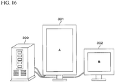
- Fig. 1 is a block diagram showing an example configuration of an image display system 100 of the present embodiment.
- the image display system 100 includes an image generation device 10 serving as a display control device and a display device 50 serving as an image display device.
- the display device 50 displays images when the image generation device 10 outputs, to the display device 50, image data generated thereby or image data captured from an external device.
- the image generation device 10 includes a control unit 11 configured to control the entire device, an input unit 12, a working area generation unit 13, a display properties setting unit 14, a pointer position monitoring unit 15, an interface unit 16, a simultaneous display command generation unit 17, a pointer movable range display unit 18, and a pointer moving distance calculation unit 19.
- the display device 50 includes a control unit 51 configured to control the entire device, an interface unit 52, a PinP circuit 53, and a display screen 54.
- the interface unit 52 sends or receives information, such as image data or command, to or from the interface unit 16 of the image generation device 10.
- the interface unit 52 includes USB/video cables and transceivers for sending or receiving sets of information, such as image data or commands, corresponding to multiple display areas.
- the PinP circuit 53 performs the function of simultaneously displaying multiple display areas (e.g., a parent screen, a child screen) on the display screen 54, that is, the picture-in-picture (PinP) function.
- the PinP circuit 53 switches between enable and disable of the PinP function in accordance with a command (PinP function enable command, PinP function disable command, or the like) outputted from the image generation device 10 (simultaneous display command generation unit 17).
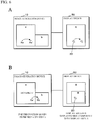
- Fig. 2 is a schematic diagram showing an example of the display screen 54 when the PinP function is enabled.
- another display area (child screen), B, is superimposed on one display area (parent screen), A, on the display screen 54 of the display device 50.
- high-resolution images such as X-ray images or CT-scan images may be displayed on the display area A
- relatively-low-resolution operation images (console images) may be displayed on the display area B.
- the position of the display area B with respect to the display area A shown in Fig. 2 is illustrative only and is not limiting.
- the single display area B is superimposed in the example of Fig. 2
- two or more display areas may be superimposed.
- the input unit 12 includes, for example, a pointing device such as a mouse or touchpad and has a function of, when the user moves the pointer to the target object on the display screen 54, receiving the movement.
- the pointer refers to, for example, a figure, character, symbol, pattern, or the like for pointing to the target object on the display screen 54.
- the working area generation unit 13 generates multiple areas corresponding to multiple display areas displayed on the display screen 54 and positions the areas in a single working area. Note that the working area generation unit 13 generates multiple areas, whether the PinP function is enabled or disabled. For example, when the multiple display areas are display areas A and B as shown in Fig. 2 , the working area generation unit 13 defines an area in the working area corresponding to the display area A as an area a, defines an area in the working area corresponding to the display area B as an area b, and positions the areas a and b in the working area. The areas a and b are positioned in the working area, for example, in such a manner to be adjacent to each other.
- the pointer In the working area, the pointer can be moved in accordance with an operation of the pointing device. That is, in the present embodiment, the "pointer” refers to the pointer displayed on the display screen, as well as the pointer in the working area. The pointer in the working area is also referred to as the "pointer position”.
- the display properties setting unit 14 sets the positions of the areas in the working area. For example, the display properties setting unit 14 defines the display area A as a parent screen (a screen displayed when the PinP function is disabled) and defines the display area B as a child screen (a screen displayed simultaneously with the parent screen when the PinP function is enabled). The display properties setting unit 14 also defines areas in the working area corresponding to the display areas A and B as areas a and b, respectively. The display properties setting unit 14 then makes settings so that the area b corresponding to the child screen is positioned adjacent to the upper, lower, left, or right side of the area a corresponding to the parent screen.
- the function of the display properties setting unit 14, that is, the positioning of the areas in the working area can be performed, for example, using a function of a program (e.g., operating system) supporting a multi-display (multi-monitor) having the PinP function.
- a program e.g., operating system
- multi-display multi-monitor
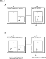
- Fig. 3 is a schematic diagram showing an example of a Display Properties/Settings window.
- the user can display the Display Properties/Settings window shown in Fig. 3 on the display screen 54 and position the area b in a desired position via the input unit 12.
- the display properties setting unit 14 sets the positions of the areas a and b, and generates position information of the display areas A and B corresponding to the areas a and b.
- Fig. 4 is a diagram showing an example of the position information.
- the position information indicates where the origin of the display area B is positioned with respect to the origin of the display area A (e.g., the upper-left corner of the display area A) or coordinates (0, 0) and can be represented, for example, by coordinates (Xs, Ys).
- the origin of the display area B may be the upper-right, lower-right, or lower-left corner thereof in place of the upper-left corner thereof in accordance with the position of the display area B in the display area A.
- the PinP circuit of the display device 50 analyzes the position information to determine the display position of the child screen.
- the image generation device 10 may analyze the position information and output the analysis result (the display position of the child screen) to the display device 50.
- the display device 50 may acquire the positions of the areas a and b from the image generation device 10 and then generate position information. If any of the parent screen and child screen is scaled up or down in the display device 50, position information is generated considering the scale-up or scale-down rate.
- Yet another alternative may be to previously determine display position options (e.g., four positions: upper-right, lower-right, upper-left, and lower-left positions) of the child screen and to select one from the display position options on the basis of the positions of the areas a and b. In this case, there is no need to generate position information.
- the pointer position monitoring unit 15 determines whether the pointer position has moved from the area a to the area b and outputs the determination to the simultaneous display command generation unit 17.
- the pointer position monitoring unit 15 determines whether the pointer position has moved from the area b to the area a and outputs the determination to the simultaneous display command generation unit 17.
- the simultaneous display command generation unit 17 When the determination is that the pointer position has moved from the area a to the area b, the simultaneous display command generation unit 17 outputs a PinP function enable command to the display device 50.
- the simultaneous display command generation unit 17 outputs a PinP function disable command to the display device 50.
- Figs. 6A and 6B are diagrams showing an example of the manner in which the PinP function is enabled based on a movement of the pointer.
- Fig. 6A shows when the PinP function is disabled
- Fig. 6B shows when the PinP function is enabled.
- the PinP function is disabled, only the display area A (parent screen) is displayed, and the pointer position in the working area moves, for example, from Xa to Xa' in the area a, which corresponds to the display area A, in accordance with a movement of a pointer 20.
- the display area B (child screen) is hidden and the pointer is displayed on the display area A. That is, only by moving the pointer on the display screen, for example, by operating the pointing device, the user can disable the PinP function and seamlessly switch between the display areas (screens) on which the pointer is displayed. In other words, the user can operate the display device with enhanced ease of use.
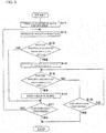
- Fig. 8 is a flowchart showing an example of a process performed by the image generation device 10 of the present embodiment.
- the process shown in Fig. 8 can be performed by recording, in a recording medium, a computer program for executing the process, loading the recorded computer program into the RAM of a computer using the recording medium reader of the computer, and causing the CPU of the computer to execute the computer program.
- the control unit 11 performs the process, for the sake of convenience.
- the control unit 11 displays the parent screen (display area A) and the pointer on the display screen 54 (S11) and monitors the pointer position in the working area (S12). The control unit 11 then determines whether the pointer position has moved from the area a to the area b (S13) and, if so determined (YES in S13), enables the PinP function to display the child screen (display area B) simultaneously with the parent screen (S14).
- control unit 11 repeats steps S12 and later; if so determined (YES in S17), it ends the process.
- step S17 If the pointer position has not moved from the area a to the area b (NO in S13), the control unit 11 performs step S17.
- control unit 11 determines whether an end operation has been performed (S18). If not so determined (NO in S18), the control unit 11 repeats steps S15 and later; if so determined (YES in S18), it ends the process.
- the areas a and b are positioned in such a manner that the area b is positioned adjacent to the right side of the area a. More specifically, the areas a and b are positioned in such a manner that a lower portion of the right side of the area a and the left side of the area b are adjacent to each other.
- the display area A parent screen
- display area B child screen
- the positions of the areas and the positional relationship between the parent screen and child screen are not limited to those described above. Other example positions will be described below.
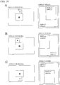
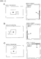
- Figs. 9A to 10C are diagrams each showing the positions of the areas and the positional relationship between the display areas.
- the left diagrams of Figs. 9A to 10C show the aspect of the display properties, that is, example positions of the areas a and b set on the Display Properties/Settings window shown in Fig. 3 (i.e., example positions of the areas in the working area).
- the rights diagrams thereof show the display positions of the display areas A and B when the PinP function is enabled.
- Fig. 9A is similar to the above example and shows a case where the areas a and b are positioned in such a manner that a lower portion of the right side of the area a and the left side of the area b are adjacent to each other.
- the display areas A (parent screen) and B (child screen) are displayed in such a manner that the display area B is superimposed on a lower-right portion of the display area A.
- the areas a and b are positioned in such a manner that the lower sides thereof are aligned with each other.
- Fig. 9B shows a case where the areas a and b are positioned in such a manner that an upper portion of the right side of the area a and the left side of the area b are adjacent to each other.
- the display areas A (parent screen) and B (child screen) are displayed in such a manner that the display area B is superimposed on an upper-right portion of the display area A.
- the areas a and b are positioned in such a manner that the upper sides thereof are aligned with each other.
- the display area B is displayed on the lower or upper-right portion of the display area A. That is, the display area B (child screen) is displayed around the position (area) which the pointer, whose movement has been kept sight of by the user, has reached.
- the user can easily continue to recognize the pointer without losing sight of it, that is, the user can operate the display device with enhanced ease of use.
- Fig. 9C shows a case where the areas a and b are positioned in such a manner that a lower portion of the left side of the area a and the right side of the area b are adjacent to each other.
- the display area A parent screen
- display area B child screen
- the areas a and b are positioned in such a manner that the lower sides thereof are aligned with each other.
- the display area B is displayed on the lower-left portion of the display area A. That is, the display area B (child screen) is displayed around the position (area) which the pointer, whose movement has been kept sight of by the user, has reached.
- the user can easily continue to recognize the pointer without losing sight of it, that is, the user can operate the display device with enhanced ease of use.
- Fig. 10A shows a case where the areas a and b are displayed in such a manner that a right portion of the upper side of the area a and the lower side of the area b are adjacent to each other.
- the display area A parent screen
- display area B child screen
- the areas a and b are positioned in such a manner that the upper side of the area a and the lower side of the area b are aligned with each other.
- Fig. 10B shows a case where the areas a and b are displayed in such a manner that a left portion of the upper side of the area a and the lower side of the area b are adjacent to each other.
- the display area A parent screen
- display area B child screen
- the areas a and b are positioned in such a manner that the upper side of the area a and the lower side of the area b are aligned with each other.
- the display area B is displayed on the upper-left or right portion of the display area A. That is, the display area B (child screen) is displayed around the position (area) which the pointer, whose movement has been kept sight of by the user, has reached.
- the user can easily continue to recognize the pointer without losing sight of it, that is, the user can operate the display device with enhanced ease of use.
- Fig. 10C shows a case where the areas a and b are displayed in such a manner that the central portion of the lower side of the area a and the upper side of the area b are adjacent to each other.
- the display area A parent screen
- display area B child screen
- the areas a and b are positioned in such a manner that the lower side of the area a and the upper side of the area b are aligned with each other.
- the pointer movable range display unit 18 displays the boundary between the area a and the area b on the display screen.
- the length of this boundary represents the adjacent range in which the areas a and b are adjacent to each other.
- the adjacent range (boundary) in which the area a and the area b are adjacent to each other is displayed on the display screen.
- the pointer position can move between the areas a and b in the adjacent range and cannot move from the area a to the area b in the non-adjacent range.
- the display of the adjacent range allows the user to easily understand in what range on the display screen he or she can move the pointer to enable or disable the PinP function. That is, the user can operate the display device with enhanced ease of use.
- the user may be forced to do the work of memorizing or searching for the position of an area which is invisible to the user, unlike in traditional multi-monitor environments, in which multiple display devices are arranged physically. According to the present configuration, such troublesome work can be eliminated.
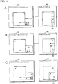
- Figs. 12A to 12C are diagrams each showing a display example of the adjacent range when the PinP function is disabled.
- the left diagrams of Figs. 12A to 12C each show the aspect of the display properties, that is, examples of the positions of the areas a and b set on the Display Properties/Settings window shown in Fig. 3 ; the right diagrams thereof each show the aspect of the display screen.
- the areas a and b are positioned in such a manner that a part of the right side of the area a and the left side of the area b are adjacent to each other. Since the pointer position can move between the areas a and b by passing through the adjacent range in which the areas a and b are adjacent to each other, the adjacent range M is displayed on a right edge of the display area A (parent screen).
- the adjacent range M can be, for example, a belt-shaped mark having a relatively outstanding color, such as red, but it may have any colors, patterns, or shapes as long as it can be recognized by the user.
- the areas a and b are positioned in such a manner that a part of the left side of the area a and the right side of the area b are adjacent to each other. Since the pointer position can move between the areas a and b by passing through the adjacent range in which the areas a and b are adjacent to each other, the adjacent range M is displayed on a left edge of the display area A (parent screen).
- the areas a and b are positioned in such a manner that a part of the upper side of the area a and the lower side of the area b are adjacent to each other. Since the pointer position can move between the areas a and b by passing through the adjacent range in which the areas a and b are adjacent to each other, the adjacent range M is displayed on an upper edge of the display area A (parent screen).
- the display area B (child screen) is displayed in such a manner to be superimposed on the display area A (parent screen). That is, when the user wants to display the child screen, he or she only has to move the pointer to the adjacent range M.
- the PinP function can be enabled to display the child screen simultaneously with the parent screen. As seen above, the user can enable the PinP function with an intuitive and simple operation.
- the boundary As described above, when another display area, B, is not displayed, the boundary (adjacent range M) is displayed on one display area, A. That is, when the PinP function is disabled and only the display area A (parent screen) is displayed on the display screen, the user only moves the pointer to the adjacent range M and moves it out of the display area A to enable the PinP function and display the display area B (child screen). That is, the user can operate the display device with enhanced ease of use.
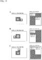
- the areas a and b are positioned in such a manner that a part of the left side of the area a and the right side of the area b are adjacent to each other. Since the pointer position can move between the areas a and b by passing through the adjacent range in which the areas a and b are adjacent to each other, the adjacent range M is displayed on the right edge of the display area B (child screen).
- the areas a and b are positioned in such a manner that a part of the upper side of the area a and the lower side of the area b are adjacent to each other. Since the pointer position can move between the areas a and b by passing through the adjacent range in which the areas a and b are adjacent to each other, the adjacent range M is displayed on the lower edge of the display area B (child screen).
- the display area B (child screen) is hidden. That is, when the user wants to hide the display area B, he or she only has to move the pointer to the adjacent range M. By doing so, the PinP function can be disabled to hide the child screen. As seen above, the user can disable the PinP function with an intuitive and simple operation.
- the boundary As described above, when another display area, B, is displayed, the boundary (adjacent range M) is displayed on the other display area, B. That is, when the PinP function is enabled and the display area A (parent screen) and display area B (child screen) are displayed on the display screen, the user only moves the pointer on the display area B to the adjacent range M and then to the display area A to disable the PinP function and hide the display area B (child screen). That is, the user can operate the display device with enhanced ease of use.
- an area a corresponding to a parent screen and areas b and c corresponding to child screens are adjacent to each other in two adjacent ranges, one between the areas a and b and another between the areas a and c.
- the adjacent ranges may have different colors, patterns, shapes, or the like so as to be distinguished from each other.
- the pointer movable range display unit 18 may be included in the display device 50.
- While the entire child screen is displayed on the parent screen at once when the PinP function is enabled in the above example, other configurations may be used.
- the child screen may be gradually displayed.
- the pointer moving distance calculation unit 19 calculates the moving distance of the pointer position. More specifically, when the pointer position moves from the area a to the area b, the pointer moving distance calculation unit 19 calculates the distance from the boundary between the areas a and b to the pointer position in the area b.
- the simultaneous display command generation unit 17 determines the expansion length with which the display area B (child screen) expands in the display area A (parent screen), in accordance with the moving distance calculated by the pointer moving distance calculation unit 19 and then outputs a PinP function enable command along with the determined expansion length to the display device 50.
- the child screen displayed based on the movement of the pointer and the parent screen are clearly distinguished from each other, allowing the user to perform an operation without being puzzled by the sudden display of the child screen.
- the child screen may be displayed with luminance which is suitable for display images on the child screen. For example, images mainly including text place a smaller burden on the eyes of the user when displayed at low luminance; images mainly including photographs or moving images look better when displayed at high luminance.
- Setting of luminance may be performed manually by the user or may be to automatically determine the contents of display images and then to set luminance which is suitable for the determined contents.
- Luminance control may be performed in the display device 50 or may be performed by hardware (graphic card) or software in the image generation device 10. Further, not only luminance but also any kind of display-related image quality, such as gradation characteristics, chromaticity, or sharpness, may be controlled. In addition to the image quality of the child screen, that of the parent screen may also be controlled, for example, using display or non-display of the child screen as a trigger.
- the user can enable or disable the PinP function. That is, the user can operate the display device simply and intuitively, in other words, with significantly enhanced ease of use.
- a virtual desktop including multiple desktops may be used as a working area using software (application, operating system, or the like).
- the image generation device 10 outputs only a desktop image (a virtual desktop image) to the display device 50 and therefore it has to be provided with a function equivalent to the PinP circuit 53.
- the child screen is displayed.
- other configurations may be used. For example, there may be used a configuration where when the user attempts to move the pointer position out of the area a by moving it across the boundary of the area a which is not adjacent to the area b, the PinP function is enabled to display the child screen. In this case, there is no need to display the adjacent range M on the boundary of the display area A (parent screen).
Landscapes
- Engineering & Computer Science (AREA)
- General Engineering & Computer Science (AREA)
- Theoretical Computer Science (AREA)
- Human Computer Interaction (AREA)
- Physics & Mathematics (AREA)
- General Physics & Mathematics (AREA)
- Multimedia (AREA)
- Signal Processing (AREA)
- Controls And Circuits For Display Device (AREA)
- User Interface Of Digital Computer (AREA)
- Digital Computer Display Output (AREA)
Claims (10)
- Anzeigesteuerungsverfahren, das einen Arbeitsbereich aufweist, in dem eine Position eines Zeigers (20) bewegt werden kann, und das auf einem Anzeigebildschirm (54) mindestens einen von einer Vielzahl von Anzeigebereichen (A, B), die dem Arbeitsbereich entsprechen, gemäß einer Bewegung der Position des Zeigers (20) anzeigt, wobei der Arbeitsbereich einen Bereich (a), der einem Anzeigebereich (A) entspricht, und einen weiteren Bereich (b), der einem weiteren Anzeigebereich (B) entspricht, umfasst, wobei das Verfahren Folgendes umfasst:Anzeigen, auf dem Anzeigebildschirm (54), des einen Anzeigebereichs (A), der dem einen Bereich (a) entspricht, Anzeigen des Zeigers (20) auf dem einen Anzeigebereich (A) und Nicht-Anzeigen, auf dem Anzeigebildschirm (54), des Anzeigebereichs (B);Bestimmen, ob sich die Position des Zeigers (20) von dem einen Bereich (a) in den anderen Bereich (b) bewegt hat;falls bestimmt wird, dass sich die Position des Zeigers (20) von dem einen Bereich (a) in den anderen Bereich (b) bewegt hat, Anzeigen, auf dem Anzeigebildschirm (54), sowohl des einen Anzeigebereichs (A) als auch des anderen Anzeigebereichs (B), der dem anderen Bereich (b) entspricht, und Anzeigen, auf dem anderen Anzeigebereich (B), des Zeigers (20), der auf dem einen Anzeigebereich (A) angezeigt worden ist;wobei eine Eingabeeinheit (12) eine Funktion des Empfangens des Bewegungsvorgangs des Zeigers und der Zeigerposition aufweist und sich die Zeigerposition auf der Basis des Bewegungsvorgangs bewegt;wobei der Bereich (a) und der Bereich (b) so positioniert sind, dass sie nebeneinanderliegen,wobei sich die Position des Zeigers (20) in dem einen Bereich (a) und dem anderen Bereich (b) auf einem Desktop bewegen kann;wobei der eine Bereich (a) und der andere Bereich (b) jedem von mehreren Monitoren entsprechen;wobei der erste Anzeigeschritt das Anzeigen, auf dem Anzeigebildschirm (54) einer Bildanzeigevorrichtung, des einen Anzeigebereichs (A) des Monitors, der dem einen Bereich (a) entspricht, beinhaltet undwobei der zweite Anzeigeschritt das Anzeigen, auf dem Anzeigebildschirm (54), sowohl des einen Anzeigebereichs (A) als auch des anderen Anzeigebereichs (B) des anderen Monitors, der dem anderen Bereich (b) entspricht, beinhaltet,wobei in dem zweiten Anzeigeschritt der eine Anzeigebereich (A) und der andere Anzeigebereich (B) als Bild im Bild angezeigt werden,wobei der andere Anzeigebereich (B) den einen Anzeigebereich (A) überlagert und wobei der eine Bereich (a) und der andere Bereich (b) nicht auf dem Anzeigebildschirm angezeigt werden.
- Anzeigesteuerungsverfahren nach Anspruch 1, ferner umfassend:
Bestimmen, ob sich nach dem Bewegen in den anderen Bereich (b) der Zeiger in den einen Bereich (a) zurückbewegt hat; und falls dies bestimmt wird, Ausblenden des anderen Anzeigebereichs (B). - Anzeigesteuerungsverfahren nach Anspruch 2, ferner umfassend das Anzeigen, auf dem Anzeigebildschirm (54), einer Grenze zwischen dem einen Bereich (a) und dem anderen Bereich (b).
- Anzeigesteuerungsverfahren nach Anspruch 3, wobei das Anzeigen der Grenze das Anzeigen der Grenze auf dem einen Anzeigebereich (A), wenn der andere Anzeigebereich (B) nicht angezeigt wird, umfasst.
- Anzeigesteuerungsverfahren nach Anspruch 3, wobei das Anzeigen der Grenze das Anzeigen der Grenze auf dem anderen Anzeigebereich (B), wenn der andere Anzeigebereich (B) angezeigt wird, umfasst.
- Anzeigesteuerungsverfahren nach einem der Ansprüche 1 bis 5, ferner umfassend:
Festlegen einer Positionsbeziehung zwischen dem einen Bereich (a) und dem anderen Bereich (b); und Bestimmen einer Anzeigeposition des anderen Anzeigebereichs (B) in Bezug auf den einen Anzeigebereich (A) auf der Basis der in dem Festlegungsschritt festgelegten Positionsbeziehung. - Anzeigesteuerungsverfahren nach einem der Ansprüche 1 bis 6, ferner umfassend:Berechnen einer Bewegungsentfernung des Zeigers von dem einen Bereich (a) zu dem anderen Bereich (b); undAnpassen einer Zone des anderen Anzeigebereichs (B), der auf dem Anzeigebildschirm (54) angezeigt wird, gemäß der in dem Berechnungsschritt berechneten Bewegungsentfernung.
- Anzeigesteuerungsverfahren nach einem der Ansprüche 1 bis 7, ferner umfassend das Steuern der Bildqualität mindestens eines der Anzeigebereiche (A, B).
- Computerprogramm, um zu bewirken, dass ein Computer einen Arbeitsbereich aufweist, in dem eine Position eines Zeigers (20) bewegt werden kann, und um auf einem Anzeigebildschirm (54) mindestens einen von einer Vielzahl von Anzeigebereichen (A, B), die dem Arbeitsbereich entsprechen, gemäß einer Bewegung der Position des Zeigers (20) anzuzeigen, wobei der Arbeitsbereich einen Bereich (a), der einem Anzeigebereich (A) entspricht, und einen weiteren Bereich (b), der einem weiteren Anzeigebereich (B) entspricht, umfasst, wobei das Computerprogramm Folgendes umfasst:Anzeigen, auf dem Anzeigebildschirm (54), des einen Anzeigebereichs (A), der dem einen Bereich (a) entspricht, Anzeigen des Zeigers (20) auf dem einen Anzeigebereich (A) und Nicht-Anzeigen, auf dem Anzeigebildschirm (54), des Anzeigebereichs (B);Bestimmen, ob sich die Position des Zeigers (20) von dem einen Bereich (a) in den anderen Bereich (b) bewegt hat;falls bestimmt wird, dass sich die Position des Zeigers (20) von dem einen Bereich (a) in den anderen Bereich (b) bewegt hat, Anzeigen, auf dem Anzeigebildschirm (54), sowohl des einen Anzeigebereichs (A) als auch des anderen Anzeigebereichs (B), der dem anderen Bereich (b) entspricht, und Anzeigen, auf dem anderen Anzeigebereich (B), des Zeigers (20), der auf dem einen Anzeigebereich (A) angezeigt worden ist, wobei eine Eingabeeinheit (12) eine Funktion des Empfangens des Bewegungsvorgangs des Zeigers und der Zeigerposition aufweist und sich die Zeigerposition auf der Basis des Bewegungsvorgangs bewegt;wobei der Bereich (a) und der Bereich (b) so positioniert sind, dass sie nebeneinanderliegen,wobei sich die Position des Zeigers (20) in dem einen Bereich (a) und dem anderen Bereich (b) auf einem Desktop bewegen kann,wobei der eine Bereich (a) und der andere Bereich (b) jedem von mehreren Monitoren entsprechen;wobei der erste Anzeigeschritt das Anzeigen, auf dem Anzeigebildschirm (54) einer Bildanzeigevorrichtung, des einen Anzeigebereichs (A) des Monitors, der dem einen Bereich (a) entspricht, beinhaltet undwobei der zweite Anzeigeschritt das Anzeigen, auf dem Anzeigebildschirm (54), sowohl des einen Anzeigebereichs (A) als auch des anderen Anzeigebereichs (B) des anderen Monitors, der dem anderen Bereich (b) entspricht, beinhaltet,wobei in dem zweiten Anzeigeschritt der eine Anzeigebereich (A) und der andere Anzeigebereich (B) als Bild im Bild angezeigt werden,wobei der andere Anzeigebereich (B) den einen Anzeigebereich (A) überlagert und wobei der eine Bereich (a) und der andere Bereich (b) nicht auf dem Anzeigebildschirm angezeigt werden.
- Bildanzeigesystem (100), umfassend:eine Anzeigesteuerungsvorrichtung (10), die einen Arbeitsbereich aufweist, in dem eine Position eines Zeigers (20) bewegt werden kann, und die auf einem Anzeigebildschirm (54) mindestens einen von einer Vielzahl von Anzeigebereichen (A, B), die dem Arbeitsbereich entsprechen, gemäß einer Bewegung der Position des Zeigers (20) anzeigt, wobei der Arbeitsbereich einen Bereich (a), der einem Anzeigebereich (A) entspricht, und einen weiteren Bereich (b), der einem weiteren Anzeigebereich (B) entspricht, umfasst; undeine Bildanzeigevorrichtung (50), die den Anzeigebildschirm (54) aufweist, auf dem die Anzeigesteuerungsvorrichtung den Zeiger (20) anzeigt, undeine Eingabeeinheit (12), die eine Funktion des Empfangens des Bewegungsvorgangs des Zeigers und der Zeigerposition aufweist,wobei sich der Zeiger und die Zeigerposition auf der Basis des Bewegungsvorgangs bewegen;wobei der Bereich (a) und der Bereich (b) so positioniert sind, dass sie nebeneinanderliegen,wobei sich die Position des Zeigers (20) in dem einen Bereich (a) und dem anderen Bereich (b) auf einem Desktop bewegen kann,wobei der eine Bereich (a) und der andere Bereich (b) jedem von mehreren Monitoren entsprechen;wobei die Anzeigesteuerungsvorrichtung (10) konfiguriert ist, um zu bestimmen, ob sich die Position des Zeigers (20) von dem einen Bereich (a) in den anderen Bereich (b) bewegt hat,wobei die Anzeigesteuerungsvorrichtung (10) konfiguriert ist,um auf dem Anzeigebildschirm (54) der Bildanzeigevorrichtung (50) den einen Anzeigebereich (A) des Monitors, der einem Bereich (a) entspricht, anzuzeigen, um den Zeiger (20) auf dem einen Anzeigebereich (A) anzuzeigen und um den Anzeigebereich (B) nicht auf dem Anzeigebildschirm (54) anzuzeigen,um auf dem Anzeigebildschirm (54) der Bildanzeigevorrichtung (50) den einen Anzeigebereich (A) des Monitors, der dem einen Bereich (a) entspricht, anzuzeigen, wobei, falls die Anzeigesteuerungsvorrichtung (10) bestimmt hat, dass sich die Position des Zeigers (20) von dem einen Bereich (a) in den anderen Bereich (b) bewegt hat,die Anzeigesteuerungsvorrichtung (10) konfiguriert ist, um auf dem Anzeigebildschirm (54) sowohl den einen Anzeigebereich (A) als auch den anderen Anzeigebereich (B) des anderen Monitors, der dem anderen Bereich (b) entspricht, anzuzeigen, und konfiguriert ist, um auf dem anderen Anzeigebereich (B) den Zeiger (20), der auf dem einen Anzeigebereich (A) angezeigt worden ist, anzuzeigen, und die Bildanzeigevorrichtung (50) konfiguriert ist, um den einen Anzeigebereich (A) und den anderen Anzeigebereich (B) auf dem Anzeigebildschirm als Bild im Bild anzuzeigen,wobei der andere Anzeigebereich (B) den einen Anzeigebereich (A) überlagert und wobei der eine Bereich (a) und der andere Bereich (b) nicht auf dem Anzeigebildschirm angezeigt werden.
Applications Claiming Priority (2)
| Application Number | Priority Date | Filing Date | Title |
|---|---|---|---|
| JP2012187825 | 2012-08-28 | ||
| PCT/JP2013/063144 WO2014034189A1 (ja) | 2012-08-28 | 2013-05-10 | 表示制御方法、コンピュータプログラム、表示制御装置及び画像表示システム |
Publications (3)
| Publication Number | Publication Date |
|---|---|
| EP2902894A1 EP2902894A1 (de) | 2015-08-05 |
| EP2902894A4 EP2902894A4 (de) | 2015-12-02 |
| EP2902894B1 true EP2902894B1 (de) | 2019-11-13 |
Family
ID=50183016
Family Applications (1)
| Application Number | Title | Priority Date | Filing Date |
|---|---|---|---|
| EP13833901.5A Active EP2902894B1 (de) | 2012-08-28 | 2013-05-10 | Anzeigesteuerungsverfahren, computerprogramm, anzeigesteuerungsvorrichtung und bildanzeigesystem |
Country Status (8)
| Country | Link |
|---|---|
| US (1) | US10795535B2 (de) |
| EP (1) | EP2902894B1 (de) |
| JP (1) | JP5728588B2 (de) |
| CN (1) | CN104603732B (de) |
| AU (1) | AU2013310588B2 (de) |
| IN (1) | IN2015DN02507A (de) |
| RU (1) | RU2619892C2 (de) |
| WO (1) | WO2014034189A1 (de) |
Families Citing this family (5)
| Publication number | Priority date | Publication date | Assignee | Title |
|---|---|---|---|---|
| JP6280435B2 (ja) * | 2014-04-28 | 2018-02-14 | 富士通コンポーネント株式会社 | プログラム、中継装置及び情報処理装置 |
| US10867445B1 (en) * | 2016-11-16 | 2020-12-15 | Amazon Technologies, Inc. | Content segmentation and navigation |
| TWI749305B (zh) * | 2019-03-20 | 2021-12-11 | 緯創資通股份有限公司 | 顯示裝置及其運作方法 |
| US11157160B1 (en) * | 2020-11-09 | 2021-10-26 | Dell Products, L.P. | Graphical user interface (GUI) for controlling virtual workspaces produced across information handling systems (IHSs) |
| CN112764844A (zh) * | 2020-12-29 | 2021-05-07 | 北京谊安医疗系统股份有限公司 | 一种生命支持系统多合一的显示系统 |
Citations (4)
| Publication number | Priority date | Publication date | Assignee | Title |
|---|---|---|---|---|
| US20010028365A1 (en) * | 1997-03-28 | 2001-10-11 | Sun Microsystems, Inc. | Method and apparatus for configuring sliding panels |
| US20080229227A1 (en) * | 2005-05-20 | 2008-09-18 | International Business Machines Corporation | Methods and Apparatus for Implementing an Integrated User Interface for Managing Multiple Virtual Machines Operative in a Computing System |
| US20110214063A1 (en) * | 2010-03-01 | 2011-09-01 | Microsoft Corporation | Efficient navigation of and interaction with a remoted desktop that is larger than the local screen |
| US20120185805A1 (en) * | 2011-01-14 | 2012-07-19 | Apple Inc. | Presenting Visual Indicators of Hidden Objects |
Family Cites Families (53)
| Publication number | Priority date | Publication date | Assignee | Title |
|---|---|---|---|---|
| DE3632601A1 (de) * | 1985-09-27 | 1987-04-23 | Olympus Optical Co | Vorrichtung zum darstellen einer positionsanzeigemarke auf mehreren bildschirmen |
| US5434625A (en) * | 1990-06-01 | 1995-07-18 | Thomson Consumer Electronics, Inc. | Formatting television pictures for side by side display |
| US5329369A (en) * | 1990-06-01 | 1994-07-12 | Thomson Consumer Electronics, Inc. | Asymmetric picture compression |
| US5420643A (en) * | 1990-06-01 | 1995-05-30 | Thomson Consumer Electronics, Inc. | Chrominance processing system for compressing and expanding video data |
| US5305435A (en) * | 1990-07-17 | 1994-04-19 | Hewlett-Packard Company | Computer windows management system and method for simulating off-screen document storage and retrieval |
| JPH0827700B2 (ja) * | 1990-12-31 | 1996-03-21 | インターナショナル・ビジネス・マシーンズ・コーポレイション | コンピュータ表示制御システム |
| JPH06274305A (ja) * | 1993-03-18 | 1994-09-30 | Hitachi Ltd | 画面表示装置及びその制御方法 |
| JPH06314181A (ja) * | 1993-04-28 | 1994-11-08 | Hitachi Ltd | 複数ディスプレイによる対話型制御システムとその制御方法 |
| US5956030A (en) * | 1993-06-11 | 1999-09-21 | Apple Computer, Inc. | Computer system with graphical user interface including windows having an identifier within a control region on the display |
| JPH08123649A (ja) * | 1994-10-20 | 1996-05-17 | Ricoh Co Ltd | メニュー表示装置 |
| US6313880B1 (en) * | 1997-04-03 | 2001-11-06 | Sony Corporation | Display with one or more display windows and placement dependent cursor and function control |
| JPH1173294A (ja) * | 1997-08-25 | 1999-03-16 | Internatl Business Mach Corp <Ibm> | ポインティング装置およびその方法 |
| US6091395A (en) * | 1997-12-15 | 2000-07-18 | International Business Machines Corporation | Computer system and method of manipulating a graphical user interface component on a computer display through collision with a pointer |
| JP2000099238A (ja) * | 1998-09-28 | 2000-04-07 | Nanao Corp | 処理情報表示装置及び情報処理画面の切り替え制御方法 |
| TW460839B (en) | 1999-01-08 | 2001-10-21 | Lg Electronics Inc | User interface method of image display device |
| JP4541476B2 (ja) * | 1999-02-19 | 2010-09-08 | キヤノン株式会社 | マルチ画像表示システムおよびマルチ画像表示方法 |
| US6373500B1 (en) * | 1999-08-19 | 2002-04-16 | Micron Technology, Inc. | Method for implementing picture-in-picture function for multiple computers |
| JP2001134378A (ja) * | 1999-11-04 | 2001-05-18 | Sharp Corp | マウスによるハードキーコントロール装置 |
| JP2002182816A (ja) * | 2000-12-14 | 2002-06-28 | Matsushita Electric Ind Co Ltd | カーソル位置指示装置 |
| JP4055359B2 (ja) * | 2000-12-14 | 2008-03-05 | 松下電器産業株式会社 | マルチディスプレイシステム |
| EP1233614B1 (de) | 2001-02-16 | 2012-08-08 | C.H.I. Development Mgmt. Ltd. XXIX, LLC | System zur Videoübertragung und Videoverarbeitung, um ein Benutzermosaik zu erzeugen |
| JP2002323968A (ja) * | 2001-04-25 | 2002-11-08 | Sharp Corp | マルチコンピュータシステム |
| US7546540B2 (en) * | 2001-05-11 | 2009-06-09 | Xerox Corporation | Methods of using mixed resolution displays |
| US7564425B2 (en) * | 2002-04-04 | 2009-07-21 | Lenovo (Singapore) Pte Ltd. | Modular display device |
| US7739604B1 (en) * | 2002-09-25 | 2010-06-15 | Apple Inc. | Method and apparatus for managing windows |
| US7142192B2 (en) * | 2002-12-12 | 2006-11-28 | Nvidia Corporation | Cursor locator for multi-monitor systems |
| US20040150649A1 (en) * | 2003-01-30 | 2004-08-05 | Jerry Moscovitch | Method and apparatus for matching multiple displays in a multi-display environment |
| US20050275641A1 (en) * | 2003-04-07 | 2005-12-15 | Matthias Franz | Computer monitor |
| EP1644816B1 (de) * | 2003-06-20 | 2016-09-14 | Apple Inc. | Computerschnittstelle mit virtuellem einzelschichtmodus zum betrachten sich überlappender objekte |
| US7665031B2 (en) * | 2004-12-08 | 2010-02-16 | Microsoft Corporation | Method and system of taskbar button interfaces |
| KR100630190B1 (ko) * | 2005-07-22 | 2006-10-02 | 삼성전자주식회사 | 이동 통신 단말의 기본화면 설정 방법 |
| US8189108B2 (en) * | 2005-08-05 | 2012-05-29 | Samsung Electronics Co., Ltd. | Apparatus for providing multiple screens and method of dynamically configuring multiple screens |
| US8191008B2 (en) | 2005-10-03 | 2012-05-29 | Citrix Systems, Inc. | Simulating multi-monitor functionality in a single monitor environment |
| CA2578640C (en) * | 2006-01-31 | 2015-04-21 | Jerry Moscovitch | Cursor management system |
| KR100827228B1 (ko) | 2006-05-01 | 2008-05-07 | 삼성전자주식회사 | 터치 기능을 갖는 영역 분할 수단을 제공하는 장치 및 그방법 |
| US8893038B2 (en) * | 2006-10-03 | 2014-11-18 | International Business Machines Corporation | Graphical association of task bar entries with corresponding desktop locations |
| US8296662B2 (en) * | 2007-02-05 | 2012-10-23 | Brother Kogyo Kabushiki Kaisha | Image display device |
| EP1956838A3 (de) | 2007-02-07 | 2009-04-29 | The DirecTV Group, Inc. | Echtzeitvideo-Verwaltungssystem |
| US8910209B2 (en) | 2007-02-07 | 2014-12-09 | The Directv Group, Inc. | Live video management system |
| US20090037822A1 (en) | 2007-07-31 | 2009-02-05 | Qurio Holdings, Inc. | Context-aware shared content representations |
| JP4412737B2 (ja) * | 2007-09-06 | 2010-02-10 | シャープ株式会社 | 情報表示装置 |
| JP5707015B2 (ja) * | 2007-09-27 | 2015-04-22 | 株式会社日立メディコ | 情報表示装置 |
| US8490019B2 (en) * | 2008-01-29 | 2013-07-16 | Microsoft Corporation | Displaying thumbnail copies of each running item from one or more applications |
| JP4535150B2 (ja) | 2008-03-18 | 2010-09-01 | ソニー株式会社 | 画像処理装置および方法、プログラム並びに記録媒体 |
| EP2299699A3 (de) * | 2009-09-04 | 2012-10-31 | Samsung Electronics Co., Ltd. | Bildverarbeitungsvorrichtung und Verfahren zur Steuerung derselben |
| JP4824805B2 (ja) * | 2009-09-28 | 2011-11-30 | 京セラ株式会社 | 携帯端末装置 |
| US8769428B2 (en) * | 2009-12-09 | 2014-07-01 | Citrix Systems, Inc. | Methods and systems for generating a combined display of taskbar button group entries generated on a local machine and on a remote machine |
| US9788046B2 (en) * | 2010-11-19 | 2017-10-10 | Sling Media Pvt Ltd. | Multistream placeshifting |
| US9015641B2 (en) * | 2011-01-06 | 2015-04-21 | Blackberry Limited | Electronic device and method of providing visual notification of a received communication |
| US9201567B2 (en) * | 2011-06-27 | 2015-12-01 | General Electric Company | Method for indicating a cursor location on a flight deck having multiple flight displays |
| US8839292B1 (en) * | 2011-12-13 | 2014-09-16 | Google Inc. | Systems and methods for rendering multiple applications on television screens |
| US20130227472A1 (en) * | 2012-02-29 | 2013-08-29 | Joseph W. Sosinski | Device, Method, and Graphical User Interface for Managing Windows |
| US9063631B2 (en) * | 2013-03-15 | 2015-06-23 | Chad Dustin TILLMAN | System and method for cooperative sharing of resources of an environment |
-
2013
- 2013-05-10 RU RU2015106614A patent/RU2619892C2/ru not_active IP Right Cessation
- 2013-05-10 US US14/424,747 patent/US10795535B2/en active Active
- 2013-05-10 IN IN2507DEN2015 patent/IN2015DN02507A/en unknown
- 2013-05-10 AU AU2013310588A patent/AU2013310588B2/en not_active Ceased
- 2013-05-10 WO PCT/JP2013/063144 patent/WO2014034189A1/ja active Application Filing
- 2013-05-10 EP EP13833901.5A patent/EP2902894B1/de active Active
- 2013-05-10 CN CN201380044816.8A patent/CN104603732B/zh active Active
- 2013-05-10 JP JP2013539077A patent/JP5728588B2/ja active Active
Patent Citations (4)
| Publication number | Priority date | Publication date | Assignee | Title |
|---|---|---|---|---|
| US20010028365A1 (en) * | 1997-03-28 | 2001-10-11 | Sun Microsystems, Inc. | Method and apparatus for configuring sliding panels |
| US20080229227A1 (en) * | 2005-05-20 | 2008-09-18 | International Business Machines Corporation | Methods and Apparatus for Implementing an Integrated User Interface for Managing Multiple Virtual Machines Operative in a Computing System |
| US20110214063A1 (en) * | 2010-03-01 | 2011-09-01 | Microsoft Corporation | Efficient navigation of and interaction with a remoted desktop that is larger than the local screen |
| US20120185805A1 (en) * | 2011-01-14 | 2012-07-19 | Apple Inc. | Presenting Visual Indicators of Hidden Objects |
Non-Patent Citations (1)
| Title |
|---|
| MARCO CHIAPPETTA: "How to set up multiple monitors In Windows 8", PC WORLD, 29 July 2012 (2012-07-29), XP055090791, Retrieved from the Internet <URL:http://www.pcworld.com/article/259794/how_to_set_up_multiple_monitors_in_windows_8.html> [retrieved on 20131128] * |
Also Published As
| Publication number | Publication date |
|---|---|
| JP5728588B2 (ja) | 2015-06-03 |
| AU2013310588A1 (en) | 2015-04-02 |
| US10795535B2 (en) | 2020-10-06 |
| RU2015106614A (ru) | 2016-10-27 |
| EP2902894A4 (de) | 2015-12-02 |
| WO2014034189A1 (ja) | 2014-03-06 |
| EP2902894A1 (de) | 2015-08-05 |
| IN2015DN02507A (de) | 2015-09-11 |
| CN104603732A (zh) | 2015-05-06 |
| US20150293663A1 (en) | 2015-10-15 |
| JPWO2014034189A1 (ja) | 2016-08-08 |
| AU2013310588B2 (en) | 2016-12-15 |
| CN104603732B (zh) | 2018-12-04 |
| RU2619892C2 (ru) | 2017-05-19 |
Similar Documents
| Publication | Publication Date | Title |
|---|---|---|
| EP2902894B1 (de) | Anzeigesteuerungsverfahren, computerprogramm, anzeigesteuerungsvorrichtung und bildanzeigesystem | |
| US8627219B2 (en) | Equipment with dual screens for controlling multi-computers and the operating method thereof | |
| CA2648614C (en) | Method of synchronizing multiple views of multiple displayed documents | |
| US20140223490A1 (en) | Apparatus and method for intuitive user interaction between multiple devices | |
| US20100107118A1 (en) | Aspect ratio hinting for resizable video windows | |
| US20110157014A1 (en) | Information processing apparatus and pointing control method | |
| EP3207450B1 (de) | Anzeigesystem mit einer virtuellen anzeige | |
| JP2007122718A (ja) | ビューポートを介して画像をパンするための方法、内部にビューポートを表示しているグラフィカルユーザインタフェースおよびもう一つのコンピューティングデバイスと対話するように構成されたコンピューティングデバイス | |
| US8184065B2 (en) | Efficient mode switching in a video processor system | |
| GB2314245A (en) | Graphical user interface | |
| EP3672265B1 (de) | Bildanzeigeverfahren | |
| WO2009013499A2 (en) | A system comprising a touchscreen and one or more conventional displays | |
| US11003340B2 (en) | Display device | |
| US20070139402A1 (en) | Image display control method | |
| US20120198381A1 (en) | Graphical user interface presenting a unified view of a main document image and thumbnail images | |
| US10459532B2 (en) | Cursor movement control method, computer program, cursor movement control device and image display system | |
| CN107066144B (zh) | 信息处理设备和信息处理方法 | |
| JP4761603B2 (ja) | 表示制御装置 | |
| RU2566975C2 (ru) | Система, способ и компьютерная программа для функционирования множества вычислительных устройств | |
| JPH09146750A (ja) | マルチウィンドウ表示装置及びその表示方法 | |
| KR20070105758A (ko) | 정보 크기 조절장치 및 그 표시방법 | |
| KR20090060005A (ko) | 다중 모니터 환경에서 화면 공유 장치 및 방법 | |
| KR20080041519A (ko) | 컴퓨터 | |
| EP2354898A1 (de) | Steuersystem und -verfahren zur Steuerung von Informationsverarbeitungsvorrichtungen | |
| JP2011210127A (ja) | 表示装置及びプログラム |
Legal Events
| Date | Code | Title | Description |
|---|---|---|---|
| PUAI | Public reference made under article 153(3) epc to a published international application that has entered the european phase |
Free format text: ORIGINAL CODE: 0009012 |
|
| 17P | Request for examination filed |
Effective date: 20150325 |
|
| AK | Designated contracting states |
Kind code of ref document: A1 Designated state(s): AL AT BE BG CH CY CZ DE DK EE ES FI FR GB GR HR HU IE IS IT LI LT LU LV MC MK MT NL NO PL PT RO RS SE SI SK SM TR |
|
| AX | Request for extension of the european patent |
Extension state: BA ME |
|
| DAX | Request for extension of the european patent (deleted) | ||
| RA4 | Supplementary search report drawn up and despatched (corrected) |
Effective date: 20151029 |
|
| RIC1 | Information provided on ipc code assigned before grant |
Ipc: G06F 3/0488 20130101ALI20151023BHEP Ipc: G06F 3/0484 20130101ALI20151023BHEP Ipc: G06F 3/048 20130101AFI20151023BHEP Ipc: G06F 3/0481 20130101ALI20151023BHEP Ipc: H04N 21/485 20110101ALI20151023BHEP Ipc: H04N 5/45 20110101ALI20151023BHEP |
|
| STAA | Information on the status of an ep patent application or granted ep patent |
Free format text: STATUS: EXAMINATION IS IN PROGRESS |
|
| 17Q | First examination report despatched |
Effective date: 20171212 |
|
| GRAP | Despatch of communication of intention to grant a patent |
Free format text: ORIGINAL CODE: EPIDOSNIGR1 |
|
| STAA | Information on the status of an ep patent application or granted ep patent |
Free format text: STATUS: GRANT OF PATENT IS INTENDED |
|
| INTG | Intention to grant announced |
Effective date: 20190709 |
|
| RIN1 | Information on inventor provided before grant (corrected) |
Inventor name: OHOTO, YOICHI Inventor name: KONO, TAKAHIRO Inventor name: KITA, MASAKI |
|
| GRAS | Grant fee paid |
Free format text: ORIGINAL CODE: EPIDOSNIGR3 |
|
| GRAA | (expected) grant |
Free format text: ORIGINAL CODE: 0009210 |
|
| STAA | Information on the status of an ep patent application or granted ep patent |
Free format text: STATUS: THE PATENT HAS BEEN GRANTED |
|
| AK | Designated contracting states |
Kind code of ref document: B1 Designated state(s): AL AT BE BG CH CY CZ DE DK EE ES FI FR GB GR HR HU IE IS IT LI LT LU LV MC MK MT NL NO PL PT RO RS SE SI SK SM TR |
|
| REG | Reference to a national code |
Ref country code: CH Ref legal event code: EP Ref country code: AT Ref legal event code: REF Ref document number: 1202361 Country of ref document: AT Kind code of ref document: T Effective date: 20191115 |
|
| REG | Reference to a national code |
Ref country code: DE Ref legal event code: R096 Ref document number: 602013062946 Country of ref document: DE |
|
| REG | Reference to a national code |
Ref country code: IE Ref legal event code: FG4D |
|
| REG | Reference to a national code |
Ref country code: NL Ref legal event code: MP Effective date: 20191113 |
|
| REG | Reference to a national code |
Ref country code: LT Ref legal event code: MG4D |
|
| PG25 | Lapsed in a contracting state [announced via postgrant information from national office to epo] |
Ref country code: GR Free format text: LAPSE BECAUSE OF FAILURE TO SUBMIT A TRANSLATION OF THE DESCRIPTION OR TO PAY THE FEE WITHIN THE PRESCRIBED TIME-LIMIT Effective date: 20200214 Ref country code: NO Free format text: LAPSE BECAUSE OF FAILURE TO SUBMIT A TRANSLATION OF THE DESCRIPTION OR TO PAY THE FEE WITHIN THE PRESCRIBED TIME-LIMIT Effective date: 20200213 Ref country code: BG Free format text: LAPSE BECAUSE OF FAILURE TO SUBMIT A TRANSLATION OF THE DESCRIPTION OR TO PAY THE FEE WITHIN THE PRESCRIBED TIME-LIMIT Effective date: 20200213 Ref country code: FI Free format text: LAPSE BECAUSE OF FAILURE TO SUBMIT A TRANSLATION OF THE DESCRIPTION OR TO PAY THE FEE WITHIN THE PRESCRIBED TIME-LIMIT Effective date: 20191113 Ref country code: LV Free format text: LAPSE BECAUSE OF FAILURE TO SUBMIT A TRANSLATION OF THE DESCRIPTION OR TO PAY THE FEE WITHIN THE PRESCRIBED TIME-LIMIT Effective date: 20191113 Ref country code: SE Free format text: LAPSE BECAUSE OF FAILURE TO SUBMIT A TRANSLATION OF THE DESCRIPTION OR TO PAY THE FEE WITHIN THE PRESCRIBED TIME-LIMIT Effective date: 20191113 Ref country code: PT Free format text: LAPSE BECAUSE OF FAILURE TO SUBMIT A TRANSLATION OF THE DESCRIPTION OR TO PAY THE FEE WITHIN THE PRESCRIBED TIME-LIMIT Effective date: 20200313 Ref country code: PL Free format text: LAPSE BECAUSE OF FAILURE TO SUBMIT A TRANSLATION OF THE DESCRIPTION OR TO PAY THE FEE WITHIN THE PRESCRIBED TIME-LIMIT Effective date: 20191113 Ref country code: LT Free format text: LAPSE BECAUSE OF FAILURE TO SUBMIT A TRANSLATION OF THE DESCRIPTION OR TO PAY THE FEE WITHIN THE PRESCRIBED TIME-LIMIT Effective date: 20191113 Ref country code: NL Free format text: LAPSE BECAUSE OF FAILURE TO SUBMIT A TRANSLATION OF THE DESCRIPTION OR TO PAY THE FEE WITHIN THE PRESCRIBED TIME-LIMIT Effective date: 20191113 |
|
| PG25 | Lapsed in a contracting state [announced via postgrant information from national office to epo] |
Ref country code: IS Free format text: LAPSE BECAUSE OF FAILURE TO SUBMIT A TRANSLATION OF THE DESCRIPTION OR TO PAY THE FEE WITHIN THE PRESCRIBED TIME-LIMIT Effective date: 20200313 Ref country code: HR Free format text: LAPSE BECAUSE OF FAILURE TO SUBMIT A TRANSLATION OF THE DESCRIPTION OR TO PAY THE FEE WITHIN THE PRESCRIBED TIME-LIMIT Effective date: 20191113 Ref country code: RS Free format text: LAPSE BECAUSE OF FAILURE TO SUBMIT A TRANSLATION OF THE DESCRIPTION OR TO PAY THE FEE WITHIN THE PRESCRIBED TIME-LIMIT Effective date: 20191113 |
|
| PG25 | Lapsed in a contracting state [announced via postgrant information from national office to epo] |
Ref country code: AL Free format text: LAPSE BECAUSE OF FAILURE TO SUBMIT A TRANSLATION OF THE DESCRIPTION OR TO PAY THE FEE WITHIN THE PRESCRIBED TIME-LIMIT Effective date: 20191113 |
|
| PG25 | Lapsed in a contracting state [announced via postgrant information from national office to epo] |
Ref country code: ES Free format text: LAPSE BECAUSE OF FAILURE TO SUBMIT A TRANSLATION OF THE DESCRIPTION OR TO PAY THE FEE WITHIN THE PRESCRIBED TIME-LIMIT Effective date: 20191113 Ref country code: DK Free format text: LAPSE BECAUSE OF FAILURE TO SUBMIT A TRANSLATION OF THE DESCRIPTION OR TO PAY THE FEE WITHIN THE PRESCRIBED TIME-LIMIT Effective date: 20191113 Ref country code: EE Free format text: LAPSE BECAUSE OF FAILURE TO SUBMIT A TRANSLATION OF THE DESCRIPTION OR TO PAY THE FEE WITHIN THE PRESCRIBED TIME-LIMIT Effective date: 20191113 Ref country code: RO Free format text: LAPSE BECAUSE OF FAILURE TO SUBMIT A TRANSLATION OF THE DESCRIPTION OR TO PAY THE FEE WITHIN THE PRESCRIBED TIME-LIMIT Effective date: 20191113 Ref country code: CZ Free format text: LAPSE BECAUSE OF FAILURE TO SUBMIT A TRANSLATION OF THE DESCRIPTION OR TO PAY THE FEE WITHIN THE PRESCRIBED TIME-LIMIT Effective date: 20191113 |
|
| REG | Reference to a national code |
Ref country code: DE Ref legal event code: R097 Ref document number: 602013062946 Country of ref document: DE |
|
| REG | Reference to a national code |
Ref country code: AT Ref legal event code: MK05 Ref document number: 1202361 Country of ref document: AT Kind code of ref document: T Effective date: 20191113 |
|
| PG25 | Lapsed in a contracting state [announced via postgrant information from national office to epo] |
Ref country code: SM Free format text: LAPSE BECAUSE OF FAILURE TO SUBMIT A TRANSLATION OF THE DESCRIPTION OR TO PAY THE FEE WITHIN THE PRESCRIBED TIME-LIMIT Effective date: 20191113 Ref country code: SK Free format text: LAPSE BECAUSE OF FAILURE TO SUBMIT A TRANSLATION OF THE DESCRIPTION OR TO PAY THE FEE WITHIN THE PRESCRIBED TIME-LIMIT Effective date: 20191113 |
|
| PLBE | No opposition filed within time limit |
Free format text: ORIGINAL CODE: 0009261 |
|
| STAA | Information on the status of an ep patent application or granted ep patent |
Free format text: STATUS: NO OPPOSITION FILED WITHIN TIME LIMIT |
|
| 26N | No opposition filed |
Effective date: 20200814 |
|
| PG25 | Lapsed in a contracting state [announced via postgrant information from national office to epo] |
Ref country code: AT Free format text: LAPSE BECAUSE OF FAILURE TO SUBMIT A TRANSLATION OF THE DESCRIPTION OR TO PAY THE FEE WITHIN THE PRESCRIBED TIME-LIMIT Effective date: 20191113 Ref country code: SI Free format text: LAPSE BECAUSE OF FAILURE TO SUBMIT A TRANSLATION OF THE DESCRIPTION OR TO PAY THE FEE WITHIN THE PRESCRIBED TIME-LIMIT Effective date: 20191113 |
|
| PG25 | Lapsed in a contracting state [announced via postgrant information from national office to epo] |
Ref country code: MC Free format text: LAPSE BECAUSE OF FAILURE TO SUBMIT A TRANSLATION OF THE DESCRIPTION OR TO PAY THE FEE WITHIN THE PRESCRIBED TIME-LIMIT Effective date: 20191113 Ref country code: CH Free format text: LAPSE BECAUSE OF NON-PAYMENT OF DUE FEES Effective date: 20200531 Ref country code: LI Free format text: LAPSE BECAUSE OF NON-PAYMENT OF DUE FEES Effective date: 20200531 |
|
| PG25 | Lapsed in a contracting state [announced via postgrant information from national office to epo] |
Ref country code: LU Free format text: LAPSE BECAUSE OF NON-PAYMENT OF DUE FEES Effective date: 20200510 |
|
| PG25 | Lapsed in a contracting state [announced via postgrant information from national office to epo] |
Ref country code: IE Free format text: LAPSE BECAUSE OF NON-PAYMENT OF DUE FEES Effective date: 20200510 |
|
| PG25 | Lapsed in a contracting state [announced via postgrant information from national office to epo] |
Ref country code: TR Free format text: LAPSE BECAUSE OF FAILURE TO SUBMIT A TRANSLATION OF THE DESCRIPTION OR TO PAY THE FEE WITHIN THE PRESCRIBED TIME-LIMIT Effective date: 20191113 Ref country code: MT Free format text: LAPSE BECAUSE OF FAILURE TO SUBMIT A TRANSLATION OF THE DESCRIPTION OR TO PAY THE FEE WITHIN THE PRESCRIBED TIME-LIMIT Effective date: 20191113 Ref country code: CY Free format text: LAPSE BECAUSE OF FAILURE TO SUBMIT A TRANSLATION OF THE DESCRIPTION OR TO PAY THE FEE WITHIN THE PRESCRIBED TIME-LIMIT Effective date: 20191113 |
|
| PG25 | Lapsed in a contracting state [announced via postgrant information from national office to epo] |
Ref country code: MK Free format text: LAPSE BECAUSE OF FAILURE TO SUBMIT A TRANSLATION OF THE DESCRIPTION OR TO PAY THE FEE WITHIN THE PRESCRIBED TIME-LIMIT Effective date: 20191113 |
|
| REG | Reference to a national code |
Ref country code: FR Ref legal event code: PLFP Year of fee payment: 11 |
|
| P01 | Opt-out of the competence of the unified patent court (upc) registered |
Effective date: 20230517 |
|
| PGFP | Annual fee paid to national office [announced via postgrant information from national office to epo] |
Ref country code: FR Payment date: 20240328 Year of fee payment: 12 |
|
| PGFP | Annual fee paid to national office [announced via postgrant information from national office to epo] |
Ref country code: GB Payment date: 20240402 Year of fee payment: 12 |
|
| PGFP | Annual fee paid to national office [announced via postgrant information from national office to epo] |
Ref country code: DE Payment date: 20240328 Year of fee payment: 12 |
|
| PGFP | Annual fee paid to national office [announced via postgrant information from national office to epo] |
Ref country code: IT Payment date: 20240411 Year of fee payment: 12 |
|
| PGFP | Annual fee paid to national office [announced via postgrant information from national office to epo] |
Ref country code: BE Payment date: 20240422 Year of fee payment: 12 |