EP2902708A1 - Gasturbinenbrennkammer für mehrere brennstoffe - Google Patents
Gasturbinenbrennkammer für mehrere brennstoffe Download PDFInfo
- Publication number
- EP2902708A1 EP2902708A1 EP14844741.0A EP14844741A EP2902708A1 EP 2902708 A1 EP2902708 A1 EP 2902708A1 EP 14844741 A EP14844741 A EP 14844741A EP 2902708 A1 EP2902708 A1 EP 2902708A1
- Authority
- EP
- European Patent Office
- Prior art keywords
- fuel
- burner
- combustion
- gas
- gas turbine
- Prior art date
- Legal status (The legal status is an assumption and is not a legal conclusion. Google has not performed a legal analysis and makes no representation as to the accuracy of the status listed.)
- Granted
Links
Images


Classifications
-
- F—MECHANICAL ENGINEERING; LIGHTING; HEATING; WEAPONS; BLASTING
- F23—COMBUSTION APPARATUS; COMBUSTION PROCESSES
- F23R—GENERATING COMBUSTION PRODUCTS OF HIGH PRESSURE OR HIGH VELOCITY, e.g. GAS-TURBINE COMBUSTION CHAMBERS
- F23R3/00—Continuous combustion chambers using liquid or gaseous fuel
- F23R3/28—Continuous combustion chambers using liquid or gaseous fuel characterised by the fuel supply
- F23R3/286—Continuous combustion chambers using liquid or gaseous fuel characterised by the fuel supply having fuel-air premixing devices
-
- F—MECHANICAL ENGINEERING; LIGHTING; HEATING; WEAPONS; BLASTING
- F02—COMBUSTION ENGINES; HOT-GAS OR COMBUSTION-PRODUCT ENGINE PLANTS
- F02C—GAS-TURBINE PLANTS; AIR INTAKES FOR JET-PROPULSION PLANTS; CONTROLLING FUEL SUPPLY IN AIR-BREATHING JET-PROPULSION PLANTS
- F02C3/00—Gas-turbine plants characterised by the use of combustion products as the working fluid
- F02C3/20—Gas-turbine plants characterised by the use of combustion products as the working fluid using a special fuel, oxidant, or dilution fluid to generate the combustion products
- F02C3/22—Gas-turbine plants characterised by the use of combustion products as the working fluid using a special fuel, oxidant, or dilution fluid to generate the combustion products the fuel or oxidant being gaseous at standard temperature and pressure
-
- F—MECHANICAL ENGINEERING; LIGHTING; HEATING; WEAPONS; BLASTING
- F02—COMBUSTION ENGINES; HOT-GAS OR COMBUSTION-PRODUCT ENGINE PLANTS
- F02C—GAS-TURBINE PLANTS; AIR INTAKES FOR JET-PROPULSION PLANTS; CONTROLLING FUEL SUPPLY IN AIR-BREATHING JET-PROPULSION PLANTS
- F02C7/00—Features, components parts, details or accessories, not provided for in, or of interest apart form groups F02C1/00 - F02C6/00; Air intakes for jet-propulsion plants
- F02C7/22—Fuel supply systems
- F02C7/222—Fuel flow conduits, e.g. manifolds
-
- F—MECHANICAL ENGINEERING; LIGHTING; HEATING; WEAPONS; BLASTING
- F02—COMBUSTION ENGINES; HOT-GAS OR COMBUSTION-PRODUCT ENGINE PLANTS
- F02C—GAS-TURBINE PLANTS; AIR INTAKES FOR JET-PROPULSION PLANTS; CONTROLLING FUEL SUPPLY IN AIR-BREATHING JET-PROPULSION PLANTS
- F02C7/00—Features, components parts, details or accessories, not provided for in, or of interest apart form groups F02C1/00 - F02C6/00; Air intakes for jet-propulsion plants
- F02C7/22—Fuel supply systems
- F02C7/232—Fuel valves; Draining valves or systems
-
- F—MECHANICAL ENGINEERING; LIGHTING; HEATING; WEAPONS; BLASTING
- F02—COMBUSTION ENGINES; HOT-GAS OR COMBUSTION-PRODUCT ENGINE PLANTS
- F02C—GAS-TURBINE PLANTS; AIR INTAKES FOR JET-PROPULSION PLANTS; CONTROLLING FUEL SUPPLY IN AIR-BREATHING JET-PROPULSION PLANTS
- F02C9/00—Controlling gas-turbine plants; Controlling fuel supply in air- breathing jet-propulsion plants
- F02C9/26—Control of fuel supply
- F02C9/40—Control of fuel supply specially adapted to the use of a special fuel or a plurality of fuels
-
- F—MECHANICAL ENGINEERING; LIGHTING; HEATING; WEAPONS; BLASTING
- F23—COMBUSTION APPARATUS; COMBUSTION PROCESSES
- F23R—GENERATING COMBUSTION PRODUCTS OF HIGH PRESSURE OR HIGH VELOCITY, e.g. GAS-TURBINE COMBUSTION CHAMBERS
- F23R3/00—Continuous combustion chambers using liquid or gaseous fuel
- F23R3/28—Continuous combustion chambers using liquid or gaseous fuel characterised by the fuel supply
- F23R3/34—Feeding into different combustion zones
- F23R3/343—Pilot flames, i.e. fuel nozzles or injectors using only a very small proportion of the total fuel to insure continuous combustion
-
- F—MECHANICAL ENGINEERING; LIGHTING; HEATING; WEAPONS; BLASTING
- F23—COMBUSTION APPARATUS; COMBUSTION PROCESSES
- F23R—GENERATING COMBUSTION PRODUCTS OF HIGH PRESSURE OR HIGH VELOCITY, e.g. GAS-TURBINE COMBUSTION CHAMBERS
- F23R3/00—Continuous combustion chambers using liquid or gaseous fuel
- F23R3/28—Continuous combustion chambers using liquid or gaseous fuel characterised by the fuel supply
- F23R3/34—Feeding into different combustion zones
- F23R3/346—Feeding into different combustion zones for staged combustion
-
- F—MECHANICAL ENGINEERING; LIGHTING; HEATING; WEAPONS; BLASTING
- F23—COMBUSTION APPARATUS; COMBUSTION PROCESSES
- F23R—GENERATING COMBUSTION PRODUCTS OF HIGH PRESSURE OR HIGH VELOCITY, e.g. GAS-TURBINE COMBUSTION CHAMBERS
- F23R3/00—Continuous combustion chambers using liquid or gaseous fuel
- F23R3/28—Continuous combustion chambers using liquid or gaseous fuel characterised by the fuel supply
- F23R3/36—Supply of different fuels
-
- F—MECHANICAL ENGINEERING; LIGHTING; HEATING; WEAPONS; BLASTING
- F23—COMBUSTION APPARATUS; COMBUSTION PROCESSES
- F23R—GENERATING COMBUSTION PRODUCTS OF HIGH PRESSURE OR HIGH VELOCITY, e.g. GAS-TURBINE COMBUSTION CHAMBERS
- F23R3/00—Continuous combustion chambers using liquid or gaseous fuel
- F23R3/42—Continuous combustion chambers using liquid or gaseous fuel characterised by the arrangement or form of the flame tubes or combustion chambers
- F23R3/46—Combustion chambers comprising an annular arrangement of several essentially tubular flame tubes within a common annular casing or within individual casings
-
- F—MECHANICAL ENGINEERING; LIGHTING; HEATING; WEAPONS; BLASTING
- F23—COMBUSTION APPARATUS; COMBUSTION PROCESSES
- F23C—METHODS OR APPARATUS FOR COMBUSTION USING FLUID FUEL OR SOLID FUEL SUSPENDED IN A CARRIER GAS OR AIR
- F23C2900/00—Special features of, or arrangements for combustion apparatus using fluid fuels or solid fuels suspended in air; Combustion processes therefor
- F23C2900/9901—Combustion process using hydrogen, hydrogen peroxide water or brown gas as fuel
-
- F—MECHANICAL ENGINEERING; LIGHTING; HEATING; WEAPONS; BLASTING
- F23—COMBUSTION APPARATUS; COMBUSTION PROCESSES
- F23D—BURNERS
- F23D2900/00—Special features of, or arrangements for burners using fluid fuels or solid fuels suspended in a carrier gas
- F23D2900/00015—Pilot burners specially adapted for low load or transient conditions, e.g. for increasing stability
-
- F—MECHANICAL ENGINEERING; LIGHTING; HEATING; WEAPONS; BLASTING
- F23—COMBUSTION APPARATUS; COMBUSTION PROCESSES
- F23R—GENERATING COMBUSTION PRODUCTS OF HIGH PRESSURE OR HIGH VELOCITY, e.g. GAS-TURBINE COMBUSTION CHAMBERS
- F23R2900/00—Special features of, or arrangements for continuous combustion chambers; Combustion processes therefor
- F23R2900/00002—Gas turbine combustors adapted for fuels having low heating value [LHV]
Definitions
- the present invention relates to a multifuel gas turbine combustor operable with the efficient utilization of hydrogen containing fuel while securing a low emission performance.
- a technology for securing a low emission performance including a low NOx emission includes, besides a wet type combustor, in which water or steam is injected into the combustor, a dry low emission (DLE) combustor in which a pre-mixture formed by mixing fuel with compressed air is injected into a combustion chamber to accomplish a leaned pre-mixture combustion, that is, a lean burn of the pre-mixture.
- This dry low emission combustor makes use of hydrocarbon system fuel such as, for example, natural gas, kerosene or diesel oil as a fuel for use in the dry low emission combustor.
- Patent Document 1 JP Laid-open Patent Publication No. 2011-075174
- Gas such as, for example, hydrogen gas is generally high in combustion velocity as compared with that of the previously mentioned hydrocarbon system fuel. Accordingly, if a substantial amount of the hydrogen gas is mixed in the fuel for the dry low emission combustor, there is a possibility that the back firing phenomenon may occur in which flames propagate through a relatively long premixing passage to such an extent as to result in heating and/or impairment.
- the patent document 1 referred to above discloses the utilization of the diffusive combustion to minimize the risk of back firing phenomenon while the hydrogen gas is used as a fuel therefor. In other words, the patent document 1 referred to above discloses a technique that is remotely far from the leaned pre-mixture combustion.
- the present invention has for its primary object to provide a multifuel gas turbine combustor, that is, a gas turbine combustor capable of operating with multifuel pre-mixture, which can combust gases containing hydrogen in a high concentration with a low NOx while maintaining a low emission performance brought about by the pre-mixture combustion.
- the present invention provides a multifuel gas turbine combustor which includes a main burner to supply a premixed gas, containing a first fuel, to a first combustion region within a combustion chamber and then to combust the premixed gas, and a supplemental burner to supply a premixed gas, containing a second fuel of a composition different from that of the first fuel, to a second combustion region at a location downstream of the first combustion region within the combustion chamber and then to combust the premixed gas.
- the first fuel is of a hydrocarbon system and the second fuel is a gas containing hydrogen in concentration exceeding a stable combustion limiting concentration of the hydrogen.
- hydrocarbon system means a gas containing hydrocarbons in a quantity equal to or higher than 60 percents by volume with the hydrogen gas not higher than the stable combustion limiting concentration, or a liquid containing hydrocarbons in a quantity equal to or higher than 60 percents by volume.
- stable combustion limiting concentration of hydrogen stands for the hydrogen concentration (volume %) at the upper limit of the boundary of whether the stable combustion is impaired as a result of the occurrence of a backfiring or is maintained when a premix containing hydrogen is formed within a main burner including a flame holding mechanism and a swirler.
- This stable combustion limiting concentration of the hydrogen is generally within the range of 8 to 15 percents by volume, but about 10 percents by weight in the embodiments of the present invention.
- the premixed gas in which the air is mixed into the second fuel, is supplied from the supplemental burner and combusted in the second combustion region and, therefore, the second furl containing the hydrogen gas, which is high in combustion velocity, can be combusted at a low combustion temperature by the introduction of the air.
- the hydrogen gas generally tending to emit a large emission of NOx can be combusted at a low NOx, that is, at a low emission.
- composition different means that the difference exists in content of the principal component or element.
- the supplemental burner may be a premixing burner operable to premix both of the first fuel and the second fuel with an air and supplying it to the second combustion region.
- the use of the premixing burner for the supplemental burner makes it possible that in the event of shortage of one of the first fuel and the second fuel, mixing an air into one of the first and second fuels, which is sufficient in quantity, and then supplying it into the second combustion region is satisfactory.
- the second fuel is employed in the form of a by-product hydrogen gas, which is generated in a chemical plant
- a required high output operation can be maintained by supplying the first fuel from the supplemental burner into the second combustion region.
- the supplemental burner may include a premixing chamber to which the air is introduced, a first nozzle to inject the first fuel into the premixing chamber, and a second nozzle to inject the second fuel into the premixing chamber.
- the supplemental burner may include a mixing chamber to which the first fuel and the second fuel are introduced, and the premixing chamber to premix the mixed fuel with the air.
- the supplemental burner may include a first burner to premix the first fuel with the air and then to inject it, and a second burner to premix the second fuel with the air and then to inject it.
- the gas turbine combustor of the present invention may further include a main fuel supply passage to supply the first fuel to the main burner, a first fuel control valve provided in the main fuel supply passage, and a first reheating fuel supply passage to supply the first fuel to the supplemental burner, the first reheating fuel supply passage being branched off from an upstream side of the first fuel control valve in the main fuel supply passage.
- the gas turbine combustor may further include a pilot burner to inject the first fuel into the first combustion region and then to accomplish a diffusion combustion thereof, and a pilot sub passage disposed in a pilot fuel supply passage to supply the first fuel to the pilot burner to introduce the second fuel during activation of the main burner.
- a pilot burner to inject the first fuel into the first combustion region and then to accomplish a diffusion combustion thereof
- a pilot sub passage disposed in a pilot fuel supply passage to supply the first fuel to the pilot burner to introduce the second fuel during activation of the main burner.
- a gas turbine engine GT to which a gas turbine combustor is applied is of a single can type as shown in Fig. 1 , but it may be of a multi-can type.
- This gas turbine engine GT includes a centrifugal compressor 1 for compressing an air A which has been sucked from an air inflow port 1a, a combustor 2 for supplying a fuel into a compressed air A to burn them, and a turbine 3 driven by a combustion gas from the combustor 2.
- the combustor 2 is disposed so as to protrude in a substantially radial direction with respect to an engine rotary shaft axis C.
- the combustion gas generated by the combustor. 2 is guided into the turbine 3 to rotate the turbine 3 to thereby drive the centrifugal compressor 1, drivingly connected with the turbine 3 through a rotary shaft 4, and a load 7 such as an electric power generator.
- Exhaust gases EG having passed through the turbine 3 are discharged to the outside through an exhaust discharge duct 8.
- the combustor 2 is of a reverse flow can type in which the compressed air A, guided from the centrifugal compressor 1 (best shown in Fig. 1 ) into an air passage 22, and the combustion gas G flow within the combustor 2 in respective directions reverse to each other.
- the combustor 2 includes a cylindrical housing H and a substantially cylindrical combustion barrel 9 accommodated within the housing H in coaxial relation therewith.
- the air passage 22 into which the air A is introduced from the centrifugal compressor 1 is formed between the housing H and the combustion barrel 9, and a combustion chamber 10 is formed within the combustion barrel 9.
- a burner unit (nozzle unit) 11 is fitted to the top of the combustion barrel 9.
- the burner unit 11 makes use of, as a first fuel F1, a hydrocarbon system fuel containing 60 or higher percents by volume of hydrocarbon.
- this hydrocarbon system fuel is in the form of natural gas.
- the hydrocarbon system fuel includes, besides the natural gas, a gaseous fuel in which the natural gas is mixed with about 5 % of hydrogen, and a liquid fuel such as, for example, kerosene or diesel oil.
- the burner unit 11 includes a main burner 12 and a pilot burner 13.
- the main burner 12 combusts a premixed gas or premixed air-fuel mixture M which contains the first fuel F 1 for premixing purpose, supplied from a first fuel supply source 18, after the premixed gas M1 has been injected into a first combustion region S1, within the combustion chamber 10.
- the pilot burner 13 diffusively combusts the first fuel F1 after the latter has been injected directly into the first combustion region S1.
- the combustion barrel 9 includes a supplemental burner 20 for accomplishing combustion by premixing with an air A both of a second fuel F2 for reheating purpose, supplied from a second fuel supply source 19, and the first fuel F1 from the first fuel supply source 18, and then injecting such a premixed gas into a second combustion region S2 downstream of the first combustion region S1 within the combustion chamber 10.
- the supplemental burner 20 is provided in a plural number and, while those of supplemental burners 20 are disposed spaced an equal distance from each other in a direction circumferentially of the combustion barrel 9, each of them traverses the air passage 22 delimited between the housing H and the combustion barrel 9.
- a gas of a composition different from that of the first fuel F1, but containing hydrogen in a concentration exceeding the stable combustion limiting concentration, for example, in a concentration exceeding 10 vol. % is employed.
- the hydrogen concentration in the second fuel F2 is preferably 20 vol. % or higher and, more preferably, 30 vol. % or higher.
- This hydrogen containing gas is in the form of, for example, a gas containing solely a hydrogen gas (100 vol. %), or a gas in which hydrogen gas is mixed with a methane gas or propane gas or an inactive gas such as nitrogen.
- the main burner 12 referred to above is disposed so as to enclose the outer periphery of the pilot burner 13 of a cylindrical shape.
- This main burner 12 includes an L-sectioned annular outer wall 121 and an annular inner wall 122, with a premixing passage 14 delimited between the outer wall 121 and the inner wall 122.
- the premixing passage 14 has an upstream end open radially outwardly and, at allocation radially outwardly of an annular air intake opening 14a so opened, a plurality of main fuel nozzles 17 are disposed spaced an equal distance from each other in a direction circumferentially of the main burner 12.
- Respective portions of the main fuel nozzles 17, which confront the air intake opening 14a, are formed with a plurality of fuel injection holes (not shown) through which the first fuel F1 is injected towards the air intake opening 14a.
- a swirler 25 is disposed in the air intake opening 14a for promoting the premixing of the first fuel F1 by swirling an inflowing air.
- the pilot burner 13 of a diffusive combustion type is disposed within an inner space of the inner wall 122.
- the supplemental burner 20 referred to previously is of a structure in which, a fuel introducing block 20a and a collared mixture injecting barrel 20b are connected with each other through a plurality of guide pieces 20c, and is supported by the housing H by means of screwing (not shown) with a tip end of the mixture injecting barrel 20b inserted into an insertion hole 41, defined in the combustion barrel 9, so as to protrude into the combustion chamber 10.
- An air inflow opening 43 provided with the guide pieces 20c is formed between a collar 20ba of the mixture injecting barrel 20b and a bottom wall 20n of the fuel introducing block 20a.
- the air inflow opening 43 is communicated with a premixing chamber 21 defined by an inner peripheral surface of the mixture injecting barrel 20b and an outer surface of the bottom wall 20n.
- the fuel introducing block 20a is provided with a first fuel introducing passage 20d for introducing the first fuel F1 from the first fuel supply source 18 from radially outwardly of the combustor 2, a second fuel introducing passage 20e for introducing the second fuel F2 from the second fuel supply source 19 from radially outwardly of the combustor 2, a first fuel chamber 20f of a cylindrical shape for reserving the first fuel F1 from the first fuel introducing passage 20d, and a second fuel chamber 20g of a cylindrical shape for reserving the second fuel F2 from the second introducing passage 20e.
- the fuel introducing block 20a also includes a first nozzle 20h in the form of a plurality of small perforations, through which the first fuel F1 within the first fuel chamber 20f is injected into the premixing chamber 21, and a second nozzle 20i in the form of a plurality of small perforations through which the second fuel F2 within the second fuel chamber 20g is injected into the premixing chamber 21.
- the guide pieces 20c which is 12 in number, for example, in the illustrated embodiment, are provided in the vicinity of an outer peripheral edge of the fuel introducing block 20a in a fashion spaced an equal distance from each other in the circumferential direction, while having been disposed coaxially with the cylindrical mixture injecting barrel 20b that is opposed relative to the fuel introducing block 20a.
- the first nozzle 20h formed in the fuel introducing block 20a is positioned at a location between the neighboring two guide pieces 20c and somewhat closer to the longitudinal axis C1 of the fuel introducing block 20a than to the guide piece 20c. Accordingly, from the first nozzle 20h, the first fuel F1 shown in Fig.
- the first fuel F1 supplied from the first fuel supply source 18 shown in Fig. 2 is, after the flow rate thereof has been adjusted by a first fuel control valve 23, injected from the main fuel nozzle 17 into the air intake opening 14a of the premixing passage 14.
- the first fuel F1 so injected is introduced into the premixing passage 14 together with the compressed air A then flowing from the air passage 22 into the air intake opening 14a while having been swirled by the swirler 25.
- the first fuel F1 is premixed with the compressed air A while flowing within the premixing passage 14, and is finally injected into the combustion chamber 10 as a premixed gas M1 from an annular premix jetting port 24.
- the first fuel control valve 23 is closed, but only a second fuel control valve 27 is opened.
- the first fuel F1 in the first fuel supply source 18 is injected from the pilot burner 13 into the combustion chamber 10 by way of the second fuel control valve 27 and the diffusive combustion takes place upon ignition of an ignition plug (not shown).
- the premixed gas M1 injected from the main burner 12 into the combustion chamber 10 is premix-combusted and, at an upstream portion of the combustion chamber 10, the first combustion region S1 is formed.
- the main burner 12 and the pilot burner 13 are so controlled that the air to fuel ratio (air flow rate/ fuel flow rate) may attain a predetermined value that is favorable to each of them.
- This first combustion region S1 can reduce, for example, NOx and CO when the first fuel F1 is subjected to a leaned premix combustion (lean burn of the premix). Also, the first combustion region S1 does not accompany any backfiring because the first fuel F 1 of the hydrocarbon system that is relatively low in combustion velocity is supplied to the main burner 12 for accomplishing the premix combustion. Therefore, in the first combustion region S1, a favorable low emission performance can be maintained.
- the second combustion region S2 for premix-combusting the premixed gas M2 injected from the supplemental burner 20 is formed on a downstream side of the first combustion region S1 in the combustion chamber 10.
- the supplemental burner 20 premixes both of the second fuel F2, which is supplied from the second fuel supply source 19 through a third fuel control valve 28, and the first fuel F1, which is supplied from the first fuel supply source 18 through a fourth control valve 29, with the compressed air A to form the premixed gas M2 which is in turn supplied to the second combustion region S2.
- This second combustion region S2 is formed so that the operating range is expanded towards a high output side in dependence on variation of the operating load of the gas turbine engine GT.
- both of the third fuel control valve 28 and the fourth fuel control valve 29 are so adjusted as to open to the opening in dependence on the variation of the operating load so that a predetermined amount of the second fuel F2 and the first fuel F1 from the respective second and first fuel supply sources 19 and 18 can be supplied to the supplemental burner 20.
- the first fuel F1 and the second fuel F2 reserved respectively within the first combustion chamber 20f and the second combustion chamber 20g are, after having been injected from the first nozzle 20h and the second nozzle 20i into the premixing chamber 21 and mixed together, premixed with the compressed air A introduced into the premixing chamber 21 from the air passage 22 by way of the air inflow opening 43. Accordingly, within the premixing chamber 21, the first fuel F1 and the second fuel F2 are sufficiently mixed with the compressed air A, then introduced from the air passage 22, to thereby form a good premixed gas M2. This premixed gas M2 is supplied from the mixture injecting barrel 20b to the second combustion region S2 within the combustion barrel 9 and is then premix-combusted.
- the hydrogen gas which is generally responsible to the generation of a large quantity of NOx, can be combusted at a low NOx.
- the supplemental burner 20 is activated under a condition in which a high temperature combustion gas G is generated as a result of general completion of combustion by the main burner 12 and the pilot burner 13, and therefore, the premixed gas M2 injected from the supplemental burner 20 has its combustion reaction accelerated stably by the high temperature combustion gas G with no flame holding mechanism.
- the first fuel F1 is added.
- a by-product hydrogen gas which is generated in a chemical plant
- the backfiring is generated starting at a relatively low speed site such as, for example, the boundary layer of a burner wall surface or a reverse flow area.
- the supplemental burner 20 does not require any flame holding mechanism and do not make use of a flame holder or a swirler for generating the reverse flow area. Therefore, the resistance to the backfiring from the reverse flow area is extremely high.
- the resistance to the backfiring from the reverse flow area is extremely high.
- the second preferred embodiment of the present invention is shown in Fig. 5 .
- components similar to those shown in Fig. 2 and described in connection with the previously described embodiment are designated by similar or identical reference numerals that are employed in Fig. 2 and, therefore, the details thereof are not reiterated for the sake of brevity.
- the gas turbine combustor 2A employed in the practice of this second embodiment, differs from the gas turbine combustor 2, which is shown in Fig. 2 and has been described in connection with the first embodiment, in respect of the structure of the supplemental burner 20A.
- the first and second fuels F1 and F2 are directly introduced into a mixing chamber 20j to form a mixture fuel.
- the mixture fuel so formed is injected into the premixing chamber 21 through a third nozzle 20k, and is then premixed with the compressed air A introduced from the air passage 22 to form the premixed gas M2.
- the premixing chamber 21 is formed, in a manner similar to that employed in the practice of the first embodiment, between an inner surface of the mixture injecting barrel 20b and the bottom wall 20n of the fuel introducing block 20a, which are connected with each other with the plurality of the guide pieces 20c intervening therebetween.
- the first fuel F1 and the second fuel F2 are injected into the premixing chamber 21, to which the compressed air A is introduced, to thereby form the premixed gas M.
- the first fuel F1 and the second fuel F2 are introduced into the mixing chamber 20j to form a mixture fuel beforehand and, subsequently, such mixture fuel is injected into the premixing chamber 21 to form the premixed gas M2. Accordingly, as a result of the mixture of the first and second fuels F1 and F2 having been accelerated, the premixed gas M2 that is further homogenous can be obtained.
- Fig. 6 illustrates a third preferred embodiment of the present invention. It is to be noted that in Fig. 6 , components similar to those shown in Fig. 2 and described in connection with the previously described embodiment are designated by similar or identical reference numerals that are employed in Fig. 2 and, therefore, the details thereof are not reiterated for the sake of brevity.
- the gas turbine combustor 2B employed in the practice of this third embodiment, differs from the gas turbine combustor 2, which is shown in Fig. 2 and has been described in connection with the first embodiment, in respect of the structure in which the supplemental burner 20B shown in Fig. 6 is of a two staged arrangement using a first burner 201 and a second burner 202 that are separately provided for the first fuel F1 and the second fuel F2.
- the first burner 201 includes a fuel chamber 20m, into which the first fuel F1 is introduced from a single first fuel introducing passage 20i, and a premixing chamber 21 for premixing the first fuel F1 with the compressed air A, which first fuel F1 is introduced from the fuel chamber 20m through a third nozzle 20k.
- the second burner 202 is also of an identical construction with the first burner 201 and the second fuel F2 is introduced into the fuel chamber 20m from a second fuel introducing passage 20i.
- the first fuel F1 is supplied to the first burner 201 through the fourth fuel control valve 29 and, also, the second fuel F2 is supplied to the second burner 202 through the third fuel control valve 28.
- a first reheating fuel supply passage 31 for the supply of the first fuel F 1 is branched from an upstream side of the first fuel control valve 23 provided in a main fuel supply passage 30.
- a fifth fuel control valve 32 is opened to supply the first fuel F1 of the first fuel supply source 18 towards a second fuel supply side through a check valve 33 so that the first fuel F1 is mixed by a mixer 34 with the second fuel F2 fed from the second fuel supply source 19 before the resultant mixture fuel is supplied to the second burner 202.
- the gas turbine combustor 2B according to this third embodiment is such that the first reheating fuel supply passage 31 is fluid connected with the main fuel supply passage 30 at a location upstream of the first fuel control valve 23, it is possible to stably supply at all times a predetermined amount of the first fuel F1 to the supplemental burner 20B, regardless of pressure fluctuation within the main fuel supply passage 30 accompanied by an adjustment of the first fuel control valve 23.
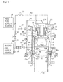
- FIG. 7 A fourth preferred embodiment of the present invention is shown in Fig. 7 . It is to be noted that in Fig. 7 , components similar to those shown in Fig. 2 and described in connection with the previously described embodiment are designated by similar or identical reference numerals that are employed in Fig. 2 and, therefore, the details thereof are not reiterated for the sake of brevity.
- the gas turbine combustor 2C employed in the practice of this fourth embodiment, includes a plurality of supplemental burners 20C of a single stage arrangement, which is of the structure identical with each of the first burner 201 and the second burner 202 that are employed in the practice of the third embodiment shown in Fig. 6 , and also a pilot burner 13A capable of supplying the second fuel F2.
- the first fuel F1 is supplied to the pilot burner 13A through a pilot fuel supply passage 37 via the second fuel control valve 27 and a check valve 38.
- a pilot sub passage 40 for introducing the second fuel F2 through a sixth fuel control valve 39 during the activation of the main burner 12 is fluid connected with the pilot fuel supply passage 37.
- the check valve 38 is operable to permit only the flow of the first fuel F1 towards the pilot burner 13A and the supplemental burner 20B.
- this gas turbine combustor 2C includes a fifth fuel control valve 32, a check valve and a mixer, which are equivalent to the fifth fuel control valve 32, the check valve 33 and the mixer 34, respectively, employed in the practice of the third embodiment shown in Fig. 6 .
- the second fuel F2 containing the hydrogen gas is supplied to the pilot burner 13A through the sixth fuel control valve 39. Therefore, combustion occurring in the pilot burner 13A is stabilized by the hydrogen gas having a high combustion temperature.
Priority Applications (1)
| Application Number | Priority Date | Filing Date | Title |
|---|---|---|---|
| EP15168221.8A EP2955445B1 (de) | 2014-06-12 | 2014-06-12 | Mehrstoffbrennkammer für eine gasturbine |
Applications Claiming Priority (1)
| Application Number | Priority Date | Filing Date | Title |
|---|---|---|---|
| PCT/JP2014/065657 WO2015037295A1 (ja) | 2014-06-12 | 2014-06-12 | マルチ燃料対応のガスタービン燃焼器 |
Related Child Applications (2)
| Application Number | Title | Priority Date | Filing Date |
|---|---|---|---|
| EP15168221.8A Division EP2955445B1 (de) | 2014-06-12 | 2014-06-12 | Mehrstoffbrennkammer für eine gasturbine |
| EP15168221.8A Division-Into EP2955445B1 (de) | 2014-06-12 | 2014-06-12 | Mehrstoffbrennkammer für eine gasturbine |
Publications (3)
| Publication Number | Publication Date |
|---|---|
| EP2902708A1 true EP2902708A1 (de) | 2015-08-05 |
| EP2902708A4 EP2902708A4 (de) | 2015-10-07 |
| EP2902708B1 EP2902708B1 (de) | 2017-02-01 |
Family
ID=52665420
Family Applications (2)
| Application Number | Title | Priority Date | Filing Date |
|---|---|---|---|
| EP14844741.0A Active EP2902708B1 (de) | 2014-06-12 | 2014-06-12 | Gasturbinenbrennkammer für mehrere brennstoffe |
| EP15168221.8A Active EP2955445B1 (de) | 2014-06-12 | 2014-06-12 | Mehrstoffbrennkammer für eine gasturbine |
Family Applications After (1)
| Application Number | Title | Priority Date | Filing Date |
|---|---|---|---|
| EP15168221.8A Active EP2955445B1 (de) | 2014-06-12 | 2014-06-12 | Mehrstoffbrennkammer für eine gasturbine |
Country Status (6)
| Country | Link |
|---|---|
| US (2) | US9400113B2 (de) |
| EP (2) | EP2902708B1 (de) |
| JP (1) | JP5759651B1 (de) |
| CN (1) | CN105452775B (de) |
| CA (1) | CA2885287C (de) |
| WO (1) | WO2015037295A1 (de) |
Cited By (8)
| Publication number | Priority date | Publication date | Assignee | Title |
|---|---|---|---|---|
| EP3220050A1 (de) * | 2016-03-16 | 2017-09-20 | Siemens Aktiengesellschaft | Brenner für eine gasturbine |
| EP3495736A1 (de) * | 2017-12-11 | 2019-06-12 | General Electric Company | Axial kraftstoffstagsystem für gasturbinenbrenner |
| EP3832208A1 (de) * | 2019-12-06 | 2021-06-09 | Raytheon Technologies Corporation | Durch wirbelkörper gesteuerter multikraftstoffinjektor mit hoher scherkraft und verfahren zur verwendung davon |
| GB2602936A (en) * | 2022-04-20 | 2022-07-20 | Derwent Tech Ltd | Propulsion system |
| WO2022182853A1 (en) * | 2021-02-25 | 2022-09-01 | Air Products And Chemicals, Inc. | Hydrogen injection for enhanced combustion stability in gas turbine systems |
| EP4116554A1 (de) * | 2021-07-05 | 2023-01-11 | Ansaldo Energia Switzerland AG | Verfahren zum betreiben einer gasturbine sowie verfahren zum nachrüsten einer gasturbine |
| EP4116555A1 (de) * | 2021-07-05 | 2023-01-11 | Ansaldo Energia Switzerland AG | Betriebsverfahren und nachrüstverfahren für eine gasturbine |
| US11808457B2 (en) | 2021-02-25 | 2023-11-07 | Air Products And Chemicals, Inc. | Hydrogen injection for enhanced combustion stability in gas turbine systems |
Families Citing this family (26)
| Publication number | Priority date | Publication date | Assignee | Title |
|---|---|---|---|---|
| CN105452775B (zh) | 2014-06-12 | 2017-09-29 | 川崎重工业株式会社 | 适合多种燃料的燃气轮机燃烧器 |
| US20160047317A1 (en) * | 2014-08-14 | 2016-02-18 | General Electric Company | Fuel injector assemblies in combustion turbine engines |
| JP6516996B2 (ja) * | 2014-10-10 | 2019-05-22 | 川崎重工業株式会社 | 燃焼器及びガスタービンエンジン |
| JP6637905B2 (ja) | 2014-12-25 | 2020-01-29 | 川崎重工業株式会社 | バーナ、燃焼器、及びガスタービン |
| US10060629B2 (en) * | 2015-02-20 | 2018-08-28 | United Technologies Corporation | Angled radial fuel/air delivery system for combustor |
| US10941940B2 (en) * | 2015-07-06 | 2021-03-09 | Siemens Energy Global GmbH & Co. KG | Burner for a gas turbine and method for operating the burner |
| JP6562883B2 (ja) | 2016-09-20 | 2019-08-21 | 株式会社東芝 | 特性値推定装置および特性値推定方法 |
| EP3301374A1 (de) * | 2016-09-29 | 2018-04-04 | Siemens Aktiengesellschaft | Pilotbrenneranordnung mit pilotluftversorgung |
| US10508811B2 (en) | 2016-10-03 | 2019-12-17 | United Technologies Corporation | Circumferential fuel shifting and biasing in an axial staged combustor for a gas turbine engine |
| CN107023854B (zh) * | 2016-12-26 | 2019-08-23 | 南方科技大学 | 一种径向进气旋流式细管预混燃油喷嘴 |
| US10415833B2 (en) | 2017-02-16 | 2019-09-17 | General Electric Company | Premixer for gas turbine combustor |
| DE102018125848A1 (de) * | 2018-10-18 | 2020-04-23 | Man Energy Solutions Se | Brennkammer einer Gasturbine, Gasturbine und Verfahren zum Betreiben derselben |
| JP7234009B2 (ja) * | 2019-03-29 | 2023-03-07 | 三菱重工業株式会社 | 燃焼器システム、及びガスタービンシステム |
| US11156164B2 (en) | 2019-05-21 | 2021-10-26 | General Electric Company | System and method for high frequency accoustic dampers with caps |
| US11174792B2 (en) | 2019-05-21 | 2021-11-16 | General Electric Company | System and method for high frequency acoustic dampers with baffles |
| KR102152420B1 (ko) * | 2019-08-23 | 2020-09-07 | 두산중공업 주식회사 | 연소기, 이를 포함하는 가스 터빈, 및 연소기의 구동 방법 |
| US20210207541A1 (en) * | 2020-01-08 | 2021-07-08 | United Technologies Corporation | Method of using a primary fuel to pilot liquid fueled combustors |
| DE112020005627T5 (de) * | 2020-02-19 | 2022-09-08 | Mitsubishi Heavy Industries Engine & Turbocharger, Ltd. | Verbrenner und gasturbine |
| US20230332544A1 (en) * | 2020-10-14 | 2023-10-19 | King Abdullah University Of Science And Technology | Adjustable fuel injector for flame dynamics control |
| GB2602037A (en) * | 2020-12-16 | 2022-06-22 | Siemens Energy Global Gmbh & Co Kg | Method of operating a combustor for a gas turbine |
| CN112815356B (zh) * | 2020-12-31 | 2022-07-15 | 哈尔滨工程大学 | 一种可自适应调节的富氢燃料低排放微焰燃烧室 |
| US20220307694A1 (en) * | 2021-03-26 | 2022-09-29 | Raytheon Technologies Corporation | Modular injector bolt for an engine |
| US11815025B2 (en) * | 2021-05-07 | 2023-11-14 | General Electric Company | Fuel nozzle |
| US11940151B2 (en) | 2022-01-12 | 2024-03-26 | General Electric Company | Combustor with baffle |
| US11885498B2 (en) * | 2022-01-31 | 2024-01-30 | General Electric Company | Turbine engine with fuel system including a catalytic reformer |
| DE102022207492A1 (de) * | 2022-07-21 | 2024-02-01 | Rolls-Royce Deutschland Ltd & Co Kg | Düsenvorrichtung zur Zugabe zumindest eines gasförmigen Kraftstoffes und eines flüssigen Kraftstoffes, Set, Zuleitungssystem und Gasturbinenanordnung |
Family Cites Families (36)
| Publication number | Priority date | Publication date | Assignee | Title |
|---|---|---|---|---|
| JPH0359143A (ja) | 1989-07-27 | 1991-03-14 | Asahi Chem Ind Co Ltd | カットパイル織編物 |
| JPH04340020A (ja) | 1991-05-15 | 1992-11-26 | Mitsubishi Heavy Ind Ltd | ガスタービン燃焼器 |
| JPH07119491A (ja) * | 1993-10-27 | 1995-05-09 | Chugoku Electric Power Co Inc:The | Lng改質ガス燃焼ガスタービン複合発電プラント |
| JP3012166B2 (ja) | 1995-02-01 | 2000-02-21 | 川崎重工業株式会社 | ガスタービン燃焼システム |
| JP3578852B2 (ja) | 1995-12-05 | 2004-10-20 | 東京瓦斯株式会社 | マルチバーナ式燃焼器の燃料供給システム及び該燃料供給システムを持つガスタービン |
| JPH1172009A (ja) | 1996-09-20 | 1999-03-16 | Toshiba Corp | 発電システム |
| DE69729038T2 (de) | 1996-09-20 | 2005-05-12 | Kabushiki Kaisha Toshiba, Kawasaki | Kraftwerk mit Trennung und Rückgewinnung von Kohlenstoffdioxid |
| GB9809371D0 (en) * | 1998-05-02 | 1998-07-01 | Rolls Royce Plc | A combustion chamber and a method of operation thereof |
| JP3775718B2 (ja) | 2000-08-18 | 2006-05-17 | 財団法人電力中央研究所 | 発電プラントおよびその運転方法 |
| US6868676B1 (en) | 2002-12-20 | 2005-03-22 | General Electric Company | Turbine containing system and an injector therefor |
| JP4400314B2 (ja) | 2004-06-02 | 2010-01-20 | 株式会社日立製作所 | ガスタービン燃焼器及びガスタービン燃焼器の燃料供給方法 |
| JP4670035B2 (ja) * | 2004-06-25 | 2011-04-13 | 独立行政法人 宇宙航空研究開発機構 | ガスタービン燃焼器 |
| JP2007113888A (ja) | 2005-10-24 | 2007-05-10 | Kawasaki Heavy Ind Ltd | ガスタービンエンジンの燃焼器構造 |
| JP5086001B2 (ja) | 2007-08-23 | 2012-11-28 | 川崎重工業株式会社 | ガスタービン燃焼装置 |
| US8387398B2 (en) | 2007-09-14 | 2013-03-05 | Siemens Energy, Inc. | Apparatus and method for controlling the secondary injection of fuel |
| WO2009109454A1 (de) | 2008-03-07 | 2009-09-11 | Alstom Technology Ltd | Verfahren und brenneranordnung zum erzeugen von heissgas sowie anwendung des verfahrens |
| EP2107300A1 (de) | 2008-04-01 | 2009-10-07 | Siemens Aktiengesellschaft | Dralleinrichtung mit Gasinjektor |
| US20100095649A1 (en) | 2008-10-20 | 2010-04-22 | General Electric Company | Staged combustion systems and methods |
| US8701382B2 (en) | 2009-01-07 | 2014-04-22 | General Electric Company | Late lean injection with expanded fuel flexibility |
| JP2010174767A (ja) * | 2009-01-30 | 2010-08-12 | Hitachi Ltd | ガスタービン,ガスタービンの制御装置及びガスタービンの点火制御方法 |
| JP2010196488A (ja) * | 2009-02-23 | 2010-09-09 | Mitsubishi Motors Corp | 可変動弁装置付エンジン |
| JP4797079B2 (ja) | 2009-03-13 | 2011-10-19 | 川崎重工業株式会社 | ガスタービン燃焼器 |
| JP5075900B2 (ja) * | 2009-09-30 | 2012-11-21 | 株式会社日立製作所 | 水素含有燃料対応燃焼器および、その低NOx運転方法 |
| US20110091829A1 (en) * | 2009-10-20 | 2011-04-21 | Vinayak Barve | Multi-fuel combustion system |
| JP5537895B2 (ja) | 2009-10-21 | 2014-07-02 | 川崎重工業株式会社 | ガスタービン燃焼器 |
| US8650851B2 (en) * | 2010-01-05 | 2014-02-18 | General Electric Company | Systems and methods for controlling fuel flow within a machine |
| JP5084847B2 (ja) | 2010-01-13 | 2012-11-28 | 株式会社日立製作所 | ガスタービン燃焼器 |
| JP5649949B2 (ja) | 2010-12-28 | 2015-01-07 | 川崎重工業株式会社 | 燃焼装置 |
| JP5393745B2 (ja) | 2011-09-05 | 2014-01-22 | 川崎重工業株式会社 | ガスタービン燃焼器 |
| WO2013043076A1 (en) * | 2011-09-22 | 2013-03-28 | General Electric Company | Combustor and method for supplying fuel to a combustor |
| US9200808B2 (en) | 2012-04-27 | 2015-12-01 | General Electric Company | System for supplying fuel to a late-lean fuel injector of a combustor |
| US9366432B2 (en) * | 2012-05-17 | 2016-06-14 | Capstone Turbine Corporation | Multistaged lean prevaporizing premixing fuel injector |
| US9291098B2 (en) | 2012-11-14 | 2016-03-22 | General Electric Company | Turbomachine and staged combustion system of a turbomachine |
| CA2894643A1 (en) * | 2012-12-13 | 2014-06-19 | Kawasaki Jukogyo Kabushiki Kaisha | Multi-fuel-capable gas turbine combustor |
| US9377202B2 (en) | 2013-03-15 | 2016-06-28 | General Electric Company | System and method for fuel blending and control in gas turbines |
| CN105452775B (zh) | 2014-06-12 | 2017-09-29 | 川崎重工业株式会社 | 适合多种燃料的燃气轮机燃烧器 |
-
2014
- 2014-06-12 CN CN201480002116.7A patent/CN105452775B/zh active Active
- 2014-06-12 EP EP14844741.0A patent/EP2902708B1/de active Active
- 2014-06-12 EP EP15168221.8A patent/EP2955445B1/de active Active
- 2014-06-12 WO PCT/JP2014/065657 patent/WO2015037295A1/ja active Application Filing
- 2014-06-12 CA CA2885287A patent/CA2885287C/en active Active
- 2014-06-12 JP JP2015508912A patent/JP5759651B1/ja active Active
- 2014-06-12 US US14/421,065 patent/US9400113B2/en active Active
-
2015
- 2015-02-12 US US14/620,874 patent/US9638423B2/en active Active
Cited By (12)
| Publication number | Priority date | Publication date | Assignee | Title |
|---|---|---|---|---|
| EP3220050A1 (de) * | 2016-03-16 | 2017-09-20 | Siemens Aktiengesellschaft | Brenner für eine gasturbine |
| EP3495736A1 (de) * | 2017-12-11 | 2019-06-12 | General Electric Company | Axial kraftstoffstagsystem für gasturbinenbrenner |
| CN109899832A (zh) * | 2017-12-11 | 2019-06-18 | 通用电气公司 | 用于燃气涡轮机燃烧器的轴向燃料分级系统 |
| CN109899832B (zh) * | 2017-12-11 | 2023-04-21 | 通用电气公司 | 用于燃气涡轮机燃烧器的轴向燃料分级系统 |
| EP3832208A1 (de) * | 2019-12-06 | 2021-06-09 | Raytheon Technologies Corporation | Durch wirbelkörper gesteuerter multikraftstoffinjektor mit hoher scherkraft und verfahren zur verwendung davon |
| WO2022182853A1 (en) * | 2021-02-25 | 2022-09-01 | Air Products And Chemicals, Inc. | Hydrogen injection for enhanced combustion stability in gas turbine systems |
| US11808457B2 (en) | 2021-02-25 | 2023-11-07 | Air Products And Chemicals, Inc. | Hydrogen injection for enhanced combustion stability in gas turbine systems |
| EP4116554A1 (de) * | 2021-07-05 | 2023-01-11 | Ansaldo Energia Switzerland AG | Verfahren zum betreiben einer gasturbine sowie verfahren zum nachrüsten einer gasturbine |
| EP4116555A1 (de) * | 2021-07-05 | 2023-01-11 | Ansaldo Energia Switzerland AG | Betriebsverfahren und nachrüstverfahren für eine gasturbine |
| GB2602936A (en) * | 2022-04-20 | 2022-07-20 | Derwent Tech Ltd | Propulsion system |
| GB2602936B (en) * | 2022-04-20 | 2023-02-15 | Derwent Tech Ltd | Propulsion system |
| EP4265898A1 (de) * | 2022-04-20 | 2023-10-25 | Derwent Technologies Ltd | Antriebssystem |
Also Published As
| Publication number | Publication date |
|---|---|
| WO2015037295A1 (ja) | 2015-03-19 |
| CA2885287A1 (en) | 2015-03-19 |
| JP5759651B1 (ja) | 2015-08-05 |
| US9400113B2 (en) | 2016-07-26 |
| EP2955445A1 (de) | 2015-12-16 |
| US20160033131A1 (en) | 2016-02-04 |
| CN105452775A (zh) | 2016-03-30 |
| EP2902708B1 (de) | 2017-02-01 |
| CN105452775B (zh) | 2017-09-29 |
| EP2955445B1 (de) | 2019-11-27 |
| CA2885287C (en) | 2016-08-30 |
| EP2902708A4 (de) | 2015-10-07 |
| US9638423B2 (en) | 2017-05-02 |
| JPWO2015037295A1 (ja) | 2017-03-02 |
| US20150362194A1 (en) | 2015-12-17 |
Similar Documents
| Publication | Publication Date | Title |
|---|---|---|
| EP2955445B1 (de) | Mehrstoffbrennkammer für eine gasturbine | |
| JP6033887B2 (ja) | マルチ燃料対応のガスタービン燃焼器 | |
| JP5364275B2 (ja) | 燃焼システムにおけるNOxエミッションを低減するのを可能にするための方法及びシステム | |
| US7260935B2 (en) | Method and apparatus for reducing gas turbine engine emissions | |
| US8117845B2 (en) | Systems to facilitate reducing flashback/flame holding in combustion systems | |
| US8973368B2 (en) | Mixer assembly for a gas turbine engine | |
| US20080016876A1 (en) | Method and apparatus for reducing gas turbine engine emissions | |
| US20140090396A1 (en) | Combustor with radially staged premixed pilot for improved | |
| WO2016072423A1 (ja) | バーナ、燃焼器、及びガスタービン | |
| JP2010159956A (ja) | 気流分割の調節による希薄遅延噴射 | |
| JP2010159955A (ja) | 燃料の融通性を得るための遅延希薄噴射 | |
| GB2432206A (en) | Low emission combustor and method of operation | |
| JP2010159758A (ja) | 燃料柔軟性を拡大した遅延希薄噴射 | |
| JPWO2009022449A1 (ja) | 燃焼装置 | |
| US9920932B2 (en) | Mixer assembly for a gas turbine engine | |
| US20040172949A1 (en) | Low emissions hydrogen blended pilot | |
| US20030101729A1 (en) | Retrofittable air assisted fuel injection method to control gaseous and acoustic emissions | |
| JP5993046B2 (ja) | マルチ燃料対応のガスタービン燃焼器 | |
| KR20100064755A (ko) | 다수 연료혼합장치가 구비된 가스터빈 저공해 연소기 |
Legal Events
| Date | Code | Title | Description |
|---|---|---|---|
| PUAI | Public reference made under article 153(3) epc to a published international application that has entered the european phase |
Free format text: ORIGINAL CODE: 0009012 |
|
| 17P | Request for examination filed |
Effective date: 20150410 |
|
| AK | Designated contracting states |
Kind code of ref document: A1 Designated state(s): AL AT BE BG CH CY CZ DE DK EE ES FI FR GB GR HR HU IE IS IT LI LT LU LV MC MK MT NL NO PL PT RO RS SE SI SK SM TR |
|
| AX | Request for extension of the european patent |
Extension state: BA ME |
|
| RA4 | Supplementary search report drawn up and despatched (corrected) |
Effective date: 20150907 |
|
| RIC1 | Information provided on ipc code assigned before grant |
Ipc: F23R 3/34 20060101AFI20150901BHEP Ipc: F23R 3/30 20060101ALI20150901BHEP Ipc: F02C 7/22 20060101ALI20150901BHEP Ipc: F23R 3/36 20060101ALI20150901BHEP |
|
| GRAP | Despatch of communication of intention to grant a patent |
Free format text: ORIGINAL CODE: EPIDOSNIGR1 |
|
| INTG | Intention to grant announced |
Effective date: 20160810 |
|
| GRAS | Grant fee paid |
Free format text: ORIGINAL CODE: EPIDOSNIGR3 |
|
| GRAA | (expected) grant |
Free format text: ORIGINAL CODE: 0009210 |
|
| DAX | Request for extension of the european patent (deleted) | ||
| AK | Designated contracting states |
Kind code of ref document: B1 Designated state(s): AL AT BE BG CH CY CZ DE DK EE ES FI FR GB GR HR HU IE IS IT LI LT LU LV MC MK MT NL NO PL PT RO RS SE SI SK SM TR |
|
| REG | Reference to a national code |
Ref country code: GB Ref legal event code: FG4D |
|
| REG | Reference to a national code |
Ref country code: CH Ref legal event code: EP Ref country code: AT Ref legal event code: REF Ref document number: 865915 Country of ref document: AT Kind code of ref document: T Effective date: 20170215 |
|
| REG | Reference to a national code |
Ref country code: IE Ref legal event code: FG4D |
|
| REG | Reference to a national code |
Ref country code: DE Ref legal event code: R096 Ref document number: 602014006662 Country of ref document: DE |
|
| REG | Reference to a national code |
Ref country code: NL Ref legal event code: MP Effective date: 20170201 |
|
| REG | Reference to a national code |
Ref country code: LT Ref legal event code: MG4D |
|
| REG | Reference to a national code |
Ref country code: AT Ref legal event code: MK05 Ref document number: 865915 Country of ref document: AT Kind code of ref document: T Effective date: 20170201 |
|
| REG | Reference to a national code |
Ref country code: FR Ref legal event code: PLFP Year of fee payment: 4 |
|
| PG25 | Lapsed in a contracting state [announced via postgrant information from national office to epo] |
Ref country code: IS Free format text: LAPSE BECAUSE OF FAILURE TO SUBMIT A TRANSLATION OF THE DESCRIPTION OR TO PAY THE FEE WITHIN THE PRESCRIBED TIME-LIMIT Effective date: 20170601 Ref country code: HR Free format text: LAPSE BECAUSE OF FAILURE TO SUBMIT A TRANSLATION OF THE DESCRIPTION OR TO PAY THE FEE WITHIN THE PRESCRIBED TIME-LIMIT Effective date: 20170201 Ref country code: LT Free format text: LAPSE BECAUSE OF FAILURE TO SUBMIT A TRANSLATION OF THE DESCRIPTION OR TO PAY THE FEE WITHIN THE PRESCRIBED TIME-LIMIT Effective date: 20170201 Ref country code: NO Free format text: LAPSE BECAUSE OF FAILURE TO SUBMIT A TRANSLATION OF THE DESCRIPTION OR TO PAY THE FEE WITHIN THE PRESCRIBED TIME-LIMIT Effective date: 20170501 Ref country code: FI Free format text: LAPSE BECAUSE OF FAILURE TO SUBMIT A TRANSLATION OF THE DESCRIPTION OR TO PAY THE FEE WITHIN THE PRESCRIBED TIME-LIMIT Effective date: 20170201 Ref country code: GR Free format text: LAPSE BECAUSE OF FAILURE TO SUBMIT A TRANSLATION OF THE DESCRIPTION OR TO PAY THE FEE WITHIN THE PRESCRIBED TIME-LIMIT Effective date: 20170502 |
|
| PG25 | Lapsed in a contracting state [announced via postgrant information from national office to epo] |
Ref country code: AT Free format text: LAPSE BECAUSE OF FAILURE TO SUBMIT A TRANSLATION OF THE DESCRIPTION OR TO PAY THE FEE WITHIN THE PRESCRIBED TIME-LIMIT Effective date: 20170201 Ref country code: SE Free format text: LAPSE BECAUSE OF FAILURE TO SUBMIT A TRANSLATION OF THE DESCRIPTION OR TO PAY THE FEE WITHIN THE PRESCRIBED TIME-LIMIT Effective date: 20170201 Ref country code: PT Free format text: LAPSE BECAUSE OF FAILURE TO SUBMIT A TRANSLATION OF THE DESCRIPTION OR TO PAY THE FEE WITHIN THE PRESCRIBED TIME-LIMIT Effective date: 20170601 Ref country code: RS Free format text: LAPSE BECAUSE OF FAILURE TO SUBMIT A TRANSLATION OF THE DESCRIPTION OR TO PAY THE FEE WITHIN THE PRESCRIBED TIME-LIMIT Effective date: 20170201 Ref country code: BG Free format text: LAPSE BECAUSE OF FAILURE TO SUBMIT A TRANSLATION OF THE DESCRIPTION OR TO PAY THE FEE WITHIN THE PRESCRIBED TIME-LIMIT Effective date: 20170501 Ref country code: LV Free format text: LAPSE BECAUSE OF FAILURE TO SUBMIT A TRANSLATION OF THE DESCRIPTION OR TO PAY THE FEE WITHIN THE PRESCRIBED TIME-LIMIT Effective date: 20170201 Ref country code: NL Free format text: LAPSE BECAUSE OF FAILURE TO SUBMIT A TRANSLATION OF THE DESCRIPTION OR TO PAY THE FEE WITHIN THE PRESCRIBED TIME-LIMIT Effective date: 20170201 Ref country code: ES Free format text: LAPSE BECAUSE OF FAILURE TO SUBMIT A TRANSLATION OF THE DESCRIPTION OR TO PAY THE FEE WITHIN THE PRESCRIBED TIME-LIMIT Effective date: 20170201 Ref country code: PL Free format text: LAPSE BECAUSE OF FAILURE TO SUBMIT A TRANSLATION OF THE DESCRIPTION OR TO PAY THE FEE WITHIN THE PRESCRIBED TIME-LIMIT Effective date: 20170201 |
|
| PGFP | Annual fee paid to national office [announced via postgrant information from national office to epo] |
Ref country code: IT Payment date: 20170630 Year of fee payment: 4 |
|
| PG25 | Lapsed in a contracting state [announced via postgrant information from national office to epo] |
Ref country code: EE Free format text: LAPSE BECAUSE OF FAILURE TO SUBMIT A TRANSLATION OF THE DESCRIPTION OR TO PAY THE FEE WITHIN THE PRESCRIBED TIME-LIMIT Effective date: 20170201 Ref country code: RO Free format text: LAPSE BECAUSE OF FAILURE TO SUBMIT A TRANSLATION OF THE DESCRIPTION OR TO PAY THE FEE WITHIN THE PRESCRIBED TIME-LIMIT Effective date: 20170201 Ref country code: CZ Free format text: LAPSE BECAUSE OF FAILURE TO SUBMIT A TRANSLATION OF THE DESCRIPTION OR TO PAY THE FEE WITHIN THE PRESCRIBED TIME-LIMIT Effective date: 20170201 Ref country code: SK Free format text: LAPSE BECAUSE OF FAILURE TO SUBMIT A TRANSLATION OF THE DESCRIPTION OR TO PAY THE FEE WITHIN THE PRESCRIBED TIME-LIMIT Effective date: 20170201 |
|
| REG | Reference to a national code |
Ref country code: DE Ref legal event code: R097 Ref document number: 602014006662 Country of ref document: DE |
|
| PG25 | Lapsed in a contracting state [announced via postgrant information from national office to epo] |
Ref country code: DK Free format text: LAPSE BECAUSE OF FAILURE TO SUBMIT A TRANSLATION OF THE DESCRIPTION OR TO PAY THE FEE WITHIN THE PRESCRIBED TIME-LIMIT Effective date: 20170201 Ref country code: SM Free format text: LAPSE BECAUSE OF FAILURE TO SUBMIT A TRANSLATION OF THE DESCRIPTION OR TO PAY THE FEE WITHIN THE PRESCRIBED TIME-LIMIT Effective date: 20170201 |
|
| PLBE | No opposition filed within time limit |
Free format text: ORIGINAL CODE: 0009261 |
|
| STAA | Information on the status of an ep patent application or granted ep patent |
Free format text: STATUS: NO OPPOSITION FILED WITHIN TIME LIMIT |
|
| 26N | No opposition filed |
Effective date: 20171103 |
|
| PG25 | Lapsed in a contracting state [announced via postgrant information from national office to epo] |
Ref country code: MC Free format text: LAPSE BECAUSE OF FAILURE TO SUBMIT A TRANSLATION OF THE DESCRIPTION OR TO PAY THE FEE WITHIN THE PRESCRIBED TIME-LIMIT Effective date: 20170201 |
|
| REG | Reference to a national code |
Ref country code: CH Ref legal event code: PL |
|
| PG25 | Lapsed in a contracting state [announced via postgrant information from national office to epo] |
Ref country code: SI Free format text: LAPSE BECAUSE OF FAILURE TO SUBMIT A TRANSLATION OF THE DESCRIPTION OR TO PAY THE FEE WITHIN THE PRESCRIBED TIME-LIMIT Effective date: 20170201 |
|
| REG | Reference to a national code |
Ref country code: IE Ref legal event code: MM4A |
|
| PG25 | Lapsed in a contracting state [announced via postgrant information from national office to epo] |
Ref country code: IE Free format text: LAPSE BECAUSE OF NON-PAYMENT OF DUE FEES Effective date: 20170612 Ref country code: CH Free format text: LAPSE BECAUSE OF NON-PAYMENT OF DUE FEES Effective date: 20170630 Ref country code: LI Free format text: LAPSE BECAUSE OF NON-PAYMENT OF DUE FEES Effective date: 20170630 Ref country code: LU Free format text: LAPSE BECAUSE OF NON-PAYMENT OF DUE FEES Effective date: 20170612 |
|
| REG | Reference to a national code |
Ref country code: BE Ref legal event code: MM Effective date: 20170630 |
|
| REG | Reference to a national code |
Ref country code: FR Ref legal event code: PLFP Year of fee payment: 5 |
|
| PG25 | Lapsed in a contracting state [announced via postgrant information from national office to epo] |
Ref country code: BE Free format text: LAPSE BECAUSE OF NON-PAYMENT OF DUE FEES Effective date: 20170630 |
|
| PG25 | Lapsed in a contracting state [announced via postgrant information from national office to epo] |
Ref country code: MT Free format text: LAPSE BECAUSE OF NON-PAYMENT OF DUE FEES Effective date: 20170612 |
|
| PG25 | Lapsed in a contracting state [announced via postgrant information from national office to epo] |
Ref country code: IT Free format text: LAPSE BECAUSE OF NON-PAYMENT OF DUE FEES Effective date: 20180612 |
|
| PG25 | Lapsed in a contracting state [announced via postgrant information from national office to epo] |
Ref country code: HU Free format text: LAPSE BECAUSE OF FAILURE TO SUBMIT A TRANSLATION OF THE DESCRIPTION OR TO PAY THE FEE WITHIN THE PRESCRIBED TIME-LIMIT; INVALID AB INITIO Effective date: 20140612 |
|
| PG25 | Lapsed in a contracting state [announced via postgrant information from national office to epo] |
Ref country code: CY Free format text: LAPSE BECAUSE OF FAILURE TO SUBMIT A TRANSLATION OF THE DESCRIPTION OR TO PAY THE FEE WITHIN THE PRESCRIBED TIME-LIMIT Effective date: 20170201 |
|
| PG25 | Lapsed in a contracting state [announced via postgrant information from national office to epo] |
Ref country code: MK Free format text: LAPSE BECAUSE OF FAILURE TO SUBMIT A TRANSLATION OF THE DESCRIPTION OR TO PAY THE FEE WITHIN THE PRESCRIBED TIME-LIMIT Effective date: 20170201 |
|
| PG25 | Lapsed in a contracting state [announced via postgrant information from national office to epo] |
Ref country code: TR Free format text: LAPSE BECAUSE OF FAILURE TO SUBMIT A TRANSLATION OF THE DESCRIPTION OR TO PAY THE FEE WITHIN THE PRESCRIBED TIME-LIMIT Effective date: 20170201 |
|
| PG25 | Lapsed in a contracting state [announced via postgrant information from national office to epo] |
Ref country code: AL Free format text: LAPSE BECAUSE OF FAILURE TO SUBMIT A TRANSLATION OF THE DESCRIPTION OR TO PAY THE FEE WITHIN THE PRESCRIBED TIME-LIMIT Effective date: 20170201 |
|
| PGFP | Annual fee paid to national office [announced via postgrant information from national office to epo] |
Ref country code: FR Payment date: 20230510 Year of fee payment: 10 Ref country code: DE Payment date: 20230502 Year of fee payment: 10 |
|
| PGFP | Annual fee paid to national office [announced via postgrant information from national office to epo] |
Ref country code: GB Payment date: 20230427 Year of fee payment: 10 |