EP2901227B1 - Method and apparatus for self verification of pressure based mass flow controllers - Google Patents
Method and apparatus for self verification of pressure based mass flow controllers Download PDFInfo
- Publication number
- EP2901227B1 EP2901227B1 EP13760193.6A EP13760193A EP2901227B1 EP 2901227 B1 EP2901227 B1 EP 2901227B1 EP 13760193 A EP13760193 A EP 13760193A EP 2901227 B1 EP2901227 B1 EP 2901227B1
- Authority
- EP
- European Patent Office
- Prior art keywords
- flow
- fluid
- reservoir
- pressure
- gas
- Prior art date
- Legal status (The legal status is an assumption and is not a legal conclusion. Google has not performed a legal analysis and makes no representation as to the accuracy of the status listed.)
- Active
Links
- 238000000034 method Methods 0.000 title claims description 42
- 238000012795 verification Methods 0.000 title claims description 31
- 239000012530 fluid Substances 0.000 claims description 70
- 238000011144 upstream manufacturing Methods 0.000 claims description 24
- 238000005259 measurement Methods 0.000 claims description 10
- 238000006243 chemical reaction Methods 0.000 claims description 4
- 238000009529 body temperature measurement Methods 0.000 claims description 3
- 238000011112 process operation Methods 0.000 claims 2
- 239000007789 gas Substances 0.000 description 27
- 230000006870 function Effects 0.000 description 13
- 238000012360 testing method Methods 0.000 description 8
- 239000004065 semiconductor Substances 0.000 description 5
- 238000009530 blood pressure measurement Methods 0.000 description 2
- 238000010586 diagram Methods 0.000 description 2
- 230000000694 effects Effects 0.000 description 2
- 230000004044 response Effects 0.000 description 2
- 230000003247 decreasing effect Effects 0.000 description 1
- 238000013461 design Methods 0.000 description 1
- 238000004519 manufacturing process Methods 0.000 description 1
- 238000012544 monitoring process Methods 0.000 description 1
Images

Classifications
-
- G—PHYSICS
- G01—MEASURING; TESTING
- G01F—MEASURING VOLUME, VOLUME FLOW, MASS FLOW OR LIQUID LEVEL; METERING BY VOLUME
- G01F1/00—Measuring the volume flow or mass flow of fluid or fluent solid material wherein the fluid passes through a meter in a continuous flow
- G01F1/05—Measuring the volume flow or mass flow of fluid or fluent solid material wherein the fluid passes through a meter in a continuous flow by using mechanical effects
- G01F1/34—Measuring the volume flow or mass flow of fluid or fluent solid material wherein the fluid passes through a meter in a continuous flow by using mechanical effects by measuring pressure or differential pressure
- G01F1/36—Measuring the volume flow or mass flow of fluid or fluent solid material wherein the fluid passes through a meter in a continuous flow by using mechanical effects by measuring pressure or differential pressure the pressure or differential pressure being created by the use of flow constriction
- G01F1/363—Measuring the volume flow or mass flow of fluid or fluent solid material wherein the fluid passes through a meter in a continuous flow by using mechanical effects by measuring pressure or differential pressure the pressure or differential pressure being created by the use of flow constriction with electrical or electro-mechanical indication
-
- G—PHYSICS
- G01—MEASURING; TESTING
- G01F—MEASURING VOLUME, VOLUME FLOW, MASS FLOW OR LIQUID LEVEL; METERING BY VOLUME
- G01F1/00—Measuring the volume flow or mass flow of fluid or fluent solid material wherein the fluid passes through a meter in a continuous flow
- G01F1/76—Devices for measuring mass flow of a fluid or a fluent solid material
- G01F1/86—Indirect mass flowmeters, e.g. measuring volume flow and density, temperature or pressure
- G01F1/88—Indirect mass flowmeters, e.g. measuring volume flow and density, temperature or pressure with differential-pressure measurement to determine the volume flow
-
- G—PHYSICS
- G01—MEASURING; TESTING
- G01F—MEASURING VOLUME, VOLUME FLOW, MASS FLOW OR LIQUID LEVEL; METERING BY VOLUME
- G01F15/00—Details of, or accessories for, apparatus of groups G01F1/00 - G01F13/00 insofar as such details or appliances are not adapted to particular types of such apparatus
- G01F15/02—Compensating or correcting for variations in pressure, density or temperature
- G01F15/022—Compensating or correcting for variations in pressure, density or temperature using electrical means
- G01F15/024—Compensating or correcting for variations in pressure, density or temperature using electrical means involving digital counting
-
- G—PHYSICS
- G01—MEASURING; TESTING
- G01F—MEASURING VOLUME, VOLUME FLOW, MASS FLOW OR LIQUID LEVEL; METERING BY VOLUME
- G01F15/00—Details of, or accessories for, apparatus of groups G01F1/00 - G01F13/00 insofar as such details or appliances are not adapted to particular types of such apparatus
- G01F15/02—Compensating or correcting for variations in pressure, density or temperature
- G01F15/04—Compensating or correcting for variations in pressure, density or temperature of gases to be measured
- G01F15/043—Compensating or correcting for variations in pressure, density or temperature of gases to be measured using electrical means
- G01F15/046—Compensating or correcting for variations in pressure, density or temperature of gases to be measured using electrical means involving digital counting
-
- G—PHYSICS
- G01—MEASURING; TESTING
- G01F—MEASURING VOLUME, VOLUME FLOW, MASS FLOW OR LIQUID LEVEL; METERING BY VOLUME
- G01F25/00—Testing or calibration of apparatus for measuring volume, volume flow or liquid level or for metering by volume
- G01F25/10—Testing or calibration of apparatus for measuring volume, volume flow or liquid level or for metering by volume of flowmeters
-
- G—PHYSICS
- G05—CONTROLLING; REGULATING
- G05D—SYSTEMS FOR CONTROLLING OR REGULATING NON-ELECTRIC VARIABLES
- G05D7/00—Control of flow
- G05D7/06—Control of flow characterised by the use of electric means
- G05D7/0617—Control of flow characterised by the use of electric means specially adapted for fluid materials
- G05D7/0629—Control of flow characterised by the use of electric means specially adapted for fluid materials characterised by the type of regulator means
- G05D7/0635—Control of flow characterised by the use of electric means specially adapted for fluid materials characterised by the type of regulator means by action on throttling means
- G05D7/0641—Control of flow characterised by the use of electric means specially adapted for fluid materials characterised by the type of regulator means by action on throttling means using a plurality of throttling means
- G05D7/0647—Control of flow characterised by the use of electric means specially adapted for fluid materials characterised by the type of regulator means by action on throttling means using a plurality of throttling means the plurality of throttling means being arranged in series
-
- Y—GENERAL TAGGING OF NEW TECHNOLOGICAL DEVELOPMENTS; GENERAL TAGGING OF CROSS-SECTIONAL TECHNOLOGIES SPANNING OVER SEVERAL SECTIONS OF THE IPC; TECHNICAL SUBJECTS COVERED BY FORMER USPC CROSS-REFERENCE ART COLLECTIONS [XRACs] AND DIGESTS
- Y10—TECHNICAL SUBJECTS COVERED BY FORMER USPC
- Y10T—TECHNICAL SUBJECTS COVERED BY FORMER US CLASSIFICATION
- Y10T137/00—Fluid handling
- Y10T137/0318—Processes
- Y10T137/0324—With control of flow by a condition or characteristic of a fluid
- Y10T137/0379—By fluid pressure
-
- Y—GENERAL TAGGING OF NEW TECHNOLOGICAL DEVELOPMENTS; GENERAL TAGGING OF CROSS-SECTIONAL TECHNOLOGIES SPANNING OVER SEVERAL SECTIONS OF THE IPC; TECHNICAL SUBJECTS COVERED BY FORMER USPC CROSS-REFERENCE ART COLLECTIONS [XRACs] AND DIGESTS
- Y10—TECHNICAL SUBJECTS COVERED BY FORMER USPC
- Y10T—TECHNICAL SUBJECTS COVERED BY FORMER US CLASSIFICATION
- Y10T137/00—Fluid handling
- Y10T137/7722—Line condition change responsive valves
- Y10T137/7758—Pilot or servo controlled
- Y10T137/7761—Electrically actuated valve
Definitions
- the present disclosure relates generally to mass flow controllers, and more particularly to self verification of pressure based mass flow controllers.
- gas is considered to include a gas or vapor.
- a mass flow controller controls and monitors the rate of fluid (i.e., a gas or vapor) flow in real time so that the flow rate of the mass of a gas passing though the device can be metered and controlled.
- Mass flow controllers are often used to control the flow of gases during a semiconductor manufacturing process wherein the flow of gases into a semiconductor tool, such as a vacuum chamber, must be carefully controlled in order to produce high yield semiconductor products.
- MFCs are usually designed and calibrated to control the flow rate of specific types of gas at particular ranges of flow rates.
- the devices control the rate of flow based on a given set point, usually predetermined by the user or an external device such as the semiconductor tool itself.
- MFCs can be either analog or digital. They are typically designed to be used with pressure ranges of the inlet gases, with low pressure and high pressure MFCs being typically available. All MFCs have an inlet port, and outlet port, a mass flow meter including a mass flow sensor and a proportional control valve.
- a system controller is used as a part of a feedback control system that provides a control signal to the control valve as a function of a comparison of the flow rate as determined by the set point with the measured flow rate as sensed by the mass flow sensor. The feedback control system thus operates the valve so that the measured flow is maintained at the flow rate as determined by the set point.
- Mass flow controllers include two types, thermal-based and pressure- based mass flow controllers, U.S. Patent Application Serial No. 13/354,988 filed January 20, 2012 in the name of Junhua Ding, entitled “System and Method of Monitoring Flow Through Mass Flow Controllers in Real Time”; and assigned the present assignee, describes a system and method for testing a thermal-based mass flow controller so that the accuracy of the mass flow controller can be verified without going off line.
- WO/2011/047361 A1 discloses a method and an apparatus for self-calibrating control of gas flow. The gas flow rate is initially set by controlling, to a high degree of precision, the amount of opening of a flow restriction, where the design of the apparatus containing the flow restriction lends itself to achieving high precision. The gas flow rate is then measured by a pressure rate-of-drop upstream of the flow restriction, and the amount of flow restriction opening is adjusted, if need be, to obtain exactly the desired flow.
- Certain embodiments of the present invention relate to a mass flow control system and method, as defined in the claims, whose accuracy can be self verified in real time when controlling a flow of a fluid to a process.
- An implementation of the system comprises:
- system further includes a second pressure sensor for providing a pressure measurement signal representative of the measured pressure of fluid downstream to the flow restrictor such that the flow rate can be measured for non-chocked flow condition.
- a method of verifying the accuracy of a mass flow control system when controlling a flow to a process comprises: controlling the flow of fluid through the system as a function of a control signal; generating the control signal as a function of measured flow of fluid through the system and a set point; and providing a known volume of the flow of fluid that is stored in a reservoir for use in verifying the accuracy of the system anytime between steps of the flow control process.
- the present disclosure relates to a pressure-based MFC.
- a pressure-based MFC There are two embodiments, one is used for choked flow conditions, and the other for non- choked flow conditions.
- one device can be configured to operate in either mode.
- Choked flow is a compressible flow effect.
- the parameter that becomes "choked” or limited is the velocity of the fluid. Choked flow is thus a fluid dynamic condition in which a fluid flowing through the MFC at a given pressure and temperature will increase in velocity as it passes through a restriction (such as an orifice of fixed cross sectional area or a nozzle) into a lower pressure environment, Choked flow is a limiting condition which occurs when the mass flow rate will not increase with a further decrease in the downstream pressure environment while upstream pressure is fixed. Under choked flow conditions, the mass flow rate can be increased by increasing the upstream pressure, or by decreasing the upstream temperature.
- the choked flow of gases is useful in many applications because the mass flow rate is independent of the downstream pressure, depending only on the temperature and pressure on the upstream side of the restriction.
- flow restrictive devices such as valves, calibrated orifice plates and nozzles can be used to produce a desired mass flow rate.
- the pressure Pd to the flow restrictor must satisfy the following criterion: P d P u ⁇ 2 ⁇ + 1 ⁇ / ⁇ ⁇ 1
- ⁇ is the specific heat ratio of the gas.
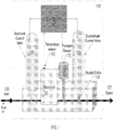
- an embodiment of the new pressure based MFC 100 is configured (a) for choke flow conditions and (b) to provide information enabling verification of the accuracy of the MFC in real time.
- the MFC 100 receives fluid 101 at an inlet 120 of MFC 100.
- the fluid is directed from the inlet 120 through a conduit of a support block to an outlet 130.
- the upstream portion of the block of MFC 100 supports an upstream control valve 125 configured to regulate the flow rate of the fluid 101 through the outlet 130 of the MFC 100 in response to and as a function of a flow control signal applied to the upstream valve.
- the upstream control valve 135 is operable in any position between a fully opened and fully closed position as a function of and in response to a flow control signal from the controller 140 so as to control the flow rate of the fluid 101 from the outlet 130 of the MFC.
- the flow control signal is generated by controller 140 as a function of a (a) set flow signal shown applied to the controller 140 and representing the desired (flow set point) flow rate of fluid through the MFC (set by a user and/or an external program from an external device such as a standalone computer or a process tool), and (b) a measured flow signal representing the measured flow rate which is a function of the pressure and temperature of the fluid flowing through the MFC.
- Controller 140 includes memory for storing calibration coefficients necessary to provide an accurate measured flow signal based the sensed temperature and pressure signals received by the system.
- this measure flow signal is provided as a function of a pressure signal provided by the pressure sensor 170 (shown in Fig. 1 in the form of a pressure transducer), and a temperature signal provided by a temperature sensor 160.
- the outlet 130 of the MFC 100 is provided with some type of flow restriction, which can be provided by the downstream control valve 135 (by controlling the position of the valve so as to create a restrictive opening), or by a separate device, such as a flow nozzle/orifice 138 which has the effect of limiting the flow and pressure of the fluid flowing from the outlet 130 under choke flow conditions.
- the MFC 100 also further includes the downstream control valve 135 supported by the block at the outlet 130, and a reservoir 150.
- the reservoir 150 is supported by the block between the upstream control valve 125 and the downstream control valve 135.
- the reservoir 150 is configured to store a known volume of fluid that flows into the MFC.
- the temperature sensor 160 is coupled to the reservoir 150 so that it measures the temperature of the wall of the reservoir, approximating the temperature of the fluid in the reservoir 150 and thus the fluid flowing in the MFC.
- the temperature sensor 160 provides to the controller 140 a signal representative of the measured temperature.
- the measured flow rate is a function of this measure temperature, as well as the pressure as measured by the pressure sensor 170.
- Pressure sensor 170 is also coupled with the outlet 130, between the upstream control valve125 and the downstream control valve 135, and configured to measure the pressure of the fluid 101 flowing through the conduit to the flow restrictor shown as a nozzle/orifice 138 of the downstream control valve 135.
- the downstream control valve 135 is open, and the flow set point is set at a non-zero value, causing the controller 140 to control the flow through the upstream valve 125 so that the measured flow will equal the non-zero set value.
- Data representing the sensed temperature and pressure is transmitted, in the form of signals from the temperature sensor 160 and the pressure sensor 170, to the controller 140 for use in determining the measured mass flow flowing through the MFC.
- the controller 140 determines the measured flow rate based on Equation (2) for a chocked flow condition:
- Q p C ′ ⁇ A ⁇ f m ⁇ T ⁇ P u ,
- C' is the orifice discharge coefficient of nozzle/orifice 138
- A the effective orifice area
- m the molecular weight of the gas
- ⁇ the specific heat capacity ratio of the gas
- T the gas temperature
- Pu the upstream pressure
- f(m, ⁇ ,T) a mathematic function which is related to the gas molecular weight m, the specific heat capacity of the gas ⁇ , and the gas temperature T.
- the controller 140 provides valve control signals to the upstream control valve 125 for controlling the flow into and out of the MFC 100 so that the measured flow rate Qp tracks the flow commanded by the flow set point.
- the two will remain substantially equal (within allowed tolerances) so long as the MFC is properly calibrated.
- downstream control valve 135 is used to define the orifice of the flow restrictor, during choke flow conditions, the position of downstream control valve 135 will remain unchanged.
- a flow verification check can be performed anytime a zero set point is commanded, as for instance the period between two steps of a gas delivery process, or following the completion of the process.
- the controller 140 automatically closes the upstream control valve 125 allowing the controller 140 to verify the flow rate based on the rate of decay of the pressure signal provided by the pressure sensor 170 as the fluid continues to flow from the reservoir 150 (which is at a higher pressure than the pressure downstream of the MFC).
- This verification period typically requires about 100-300 msec to perform the measurement. In certain embodiments, the verification period may be between 100 to 300 milliseconds.
- fluid 101 from the reservoir 150 is directed out the outlet 130 of the MFC 100.
- downstream control valve 135 is completely closed to prevent any remaining fluid 101 from exiting the MFC 100.
- MFC 100 verifies the calculated flow rate Qp using Equation (2) against the rate of decay flow rate, Qv as determined in accordance with Equation (3).
- the MFC 100 can send out an alarm to the host controller (not shown) to warn of the out of calibration condition.
- the MFC 100 can mathematically adjust or update the coefficients such as C ' and / or A in the flow calculation Equation (2) based on the verified value of Q v such that the flow error between Q p and Q v is minimized, at or below the predetermined accuracy tolerance limit.
- the MFC 100 is recalibrated within the tolerance limits during the flow verification period.
- the MFC 100 uses the verified value of the flow rate to achieve the target flow rate, at which the fluid exits the system.
- Fig. 2 shows an embodiment for operating the MFC for non-choke flow conditions.
- the MFC 200 includes the same or similar components as the Fig. 1 embodiment, but with an additional pressure sensor (shown as second pressure transducer 180) arranged to sense the pressure of the gas downstream from the flow restrictor 138.
- the second pressure transducer 180 can be mounted to the block, or mounted separate from the block.
- Fig. 2 can be used for both choked flow conditions and non-choked flow conditions.
- the mode of operation of the Fig. 2 embodiment is thus determined whether the MFC 250 is to be operated for choked flow conditions or non-choked flow conditions.
- f is a mathematic function of the upstream pressure P u , the downstream pressure P d , the gas temperature T , the gas molecular weight m , the gas specific heat ratio ⁇ and the effective office area A.
- Data relating to the values of Qp and Qv can be accumulated in the controller 140 and the data related to Qp and Qv can then be compared to determine whether the MFC is out of certain calibration tolerances. Further, the coefficients in Equation (4) can be updated to minimize the flow error between Qv and Qp. Hence, the MFC 200 is recalibrated during the flow verification period.
- the foregoing is a system and method for continually testing and verifying the calibration settings of a MFC in real time while processes are being run.
- the system can also do self-calibration by adjusting the flow calculation coefficients based on the verification results if there are differences between the current coefficients stored in the memory of the controller 140, and coefficients determined from the measurements made by the system.
- the coefficients of a flow calculation equation for the measured flow rate Qp can be recalculated based on the verification results such that the flow error between Qp and Qv is minimized, at or below a predetermined accuracy tolerance limit so as to recalibrate the system within the tolerance limits during the flow verification period.
Applications Claiming Priority (2)
| Application Number | Priority Date | Filing Date | Title |
|---|---|---|---|
| US13/626,432 US10031005B2 (en) | 2012-09-25 | 2012-09-25 | Method and apparatus for self verification of pressure-based mass flow controllers |
| PCT/US2013/057184 WO2014051925A1 (en) | 2012-09-25 | 2013-08-29 | Method and apparatus for self verification of pressure based mass flow controllers |
Publications (2)
| Publication Number | Publication Date |
|---|---|
| EP2901227A1 EP2901227A1 (en) | 2015-08-05 |
| EP2901227B1 true EP2901227B1 (en) | 2019-03-06 |
Family
ID=49162251
Family Applications (1)
| Application Number | Title | Priority Date | Filing Date |
|---|---|---|---|
| EP13760193.6A Active EP2901227B1 (en) | 2012-09-25 | 2013-08-29 | Method and apparatus for self verification of pressure based mass flow controllers |
Country Status (8)
| Country | Link |
|---|---|
| US (2) | US10031005B2 (ko) |
| EP (1) | EP2901227B1 (ko) |
| JP (1) | JP6093019B2 (ko) |
| KR (1) | KR101662046B1 (ko) |
| CN (1) | CN104704434B (ko) |
| SG (1) | SG11201501847VA (ko) |
| TW (1) | TWI561948B (ko) |
| WO (1) | WO2014051925A1 (ko) |
Families Citing this family (59)
| Publication number | Priority date | Publication date | Assignee | Title |
|---|---|---|---|---|
| US9188989B1 (en) | 2011-08-20 | 2015-11-17 | Daniel T. Mudd | Flow node to deliver process gas using a remote pressure measurement device |
| US9958302B2 (en) | 2011-08-20 | 2018-05-01 | Reno Technologies, Inc. | Flow control system, method, and apparatus |
| JP5665793B2 (ja) * | 2012-04-26 | 2015-02-04 | 株式会社フジキン | 可変オリフィス型圧力制御式流量制御器 |
| US10031005B2 (en) * | 2012-09-25 | 2018-07-24 | Mks Instruments, Inc. | Method and apparatus for self verification of pressure-based mass flow controllers |
| US8845940B2 (en) | 2012-10-25 | 2014-09-30 | Carboncure Technologies Inc. | Carbon dioxide treatment of concrete upstream from product mold |
| CA2900049C (en) | 2013-02-04 | 2020-08-18 | Coldcrete, Inc. | System and method of applying carbon dioxide during the production of concrete |
| US20160107939A1 (en) | 2014-04-09 | 2016-04-21 | Carboncure Technologies Inc. | Methods and compositions for concrete production |
| US10927042B2 (en) | 2013-06-25 | 2021-02-23 | Carboncure Technologies, Inc. | Methods and compositions for concrete production |
| US9388072B2 (en) | 2013-06-25 | 2016-07-12 | Carboncure Technologies Inc. | Methods and compositions for concrete production |
| US9376345B2 (en) * | 2013-06-25 | 2016-06-28 | Carboncure Technologies Inc. | Methods for delivery of carbon dioxide to a flowable concrete mix |
| US9108883B2 (en) | 2013-06-25 | 2015-08-18 | Carboncure Technologies, Inc. | Apparatus for carbonation of a cement mix |
| WO2015123769A1 (en) | 2014-02-18 | 2015-08-27 | Carboncure Technologies, Inc. | Carbonation of cement mixes |
| US9605346B2 (en) * | 2014-03-28 | 2017-03-28 | Lam Research Corporation | Systems and methods for pressure-based liquid flow control |
| CA2943791C (en) | 2014-04-07 | 2023-09-05 | Carboncure Technologies Inc. | Integrated carbon dioxide capture |
| KR102579543B1 (ko) * | 2015-08-31 | 2023-09-18 | 엠케이에스 인스트루먼츠, 인코포레이티드 | 비임계적 흐름 조건에서 압력 기반의 흐름 측정을 위한 방법 및 장치 |
| US10126761B2 (en) | 2015-12-29 | 2018-11-13 | Hitachi Metals, Ltd. | Gas insensitive mass flow control systems and methods |
| US10312119B2 (en) * | 2016-02-17 | 2019-06-04 | Lam Research Corporation | Line charge volume with integrated pressure measurement |
| US10515783B2 (en) | 2016-02-23 | 2019-12-24 | Lam Research Corporation | Flow through line charge volume |
| CA3019860A1 (en) | 2016-04-11 | 2017-10-19 | Carboncure Technologies Inc. | Methods and compositions for treatment of concrete wash water |
| US10684159B2 (en) | 2016-06-27 | 2020-06-16 | Applied Materials, Inc. | Methods, systems, and apparatus for mass flow verification based on choked flow |
| US10838437B2 (en) | 2018-02-22 | 2020-11-17 | Ichor Systems, Inc. | Apparatus for splitting flow of process gas and method of operating same |
| US10303189B2 (en) | 2016-06-30 | 2019-05-28 | Reno Technologies, Inc. | Flow control system, method, and apparatus |
| US10679880B2 (en) | 2016-09-27 | 2020-06-09 | Ichor Systems, Inc. | Method of achieving improved transient response in apparatus for controlling flow and system for accomplishing same |
| US11144075B2 (en) | 2016-06-30 | 2021-10-12 | Ichor Systems, Inc. | Flow control system, method, and apparatus |
| US20190204133A1 (en) * | 2016-09-19 | 2019-07-04 | Flow Devices And Systems Inc. | Variable Restriction for Flow Measurement |
| US10031004B2 (en) | 2016-12-15 | 2018-07-24 | Mks Instruments, Inc. | Methods and apparatus for wide range mass flow verification |
| US10663337B2 (en) | 2016-12-30 | 2020-05-26 | Ichor Systems, Inc. | Apparatus for controlling flow and method of calibrating same |
| US20190352888A1 (en) * | 2017-01-14 | 2019-11-21 | Mario LARACH | Smart monitoring unit apparatus for real-time monitoring and active management of upstream and downstream pressure and flow, incorporating self-cleaning and plug-and-play maintenance |
| MX2019015651A (es) | 2017-06-20 | 2020-08-03 | Carboncure Tech Inc | Métodos y composiciones para tratamiento de agua de lavado de concreto. |
| JP6811147B2 (ja) * | 2017-06-23 | 2021-01-13 | 東京エレクトロン株式会社 | ガス供給系を検査する方法 |
| JP7164938B2 (ja) * | 2017-07-31 | 2022-11-02 | 株式会社堀場エステック | 流量制御装置、流量制御方法、及び、流量制御装置用プログラム |
| US10738754B2 (en) * | 2017-09-26 | 2020-08-11 | The Boeing Company | Rapid sample ignition test system |
| JP7131561B2 (ja) * | 2017-09-29 | 2022-09-06 | 日立金属株式会社 | 質量流量制御システム並びに当該システムを含む半導体製造装置及び気化器 |
| KR20190050611A (ko) * | 2017-11-03 | 2019-05-13 | 삼성전자주식회사 | 모니터링 장치 및 이를 포함하는 반도체 제조 장치 |
| US20200297982A1 (en) * | 2017-11-20 | 2020-09-24 | The Regents Of The University Of Michigan | Digital external ventricular drain with integrated intracranial pressure monitor and cerebral spinal fluid monitor/pressure regulator |
| US11174625B2 (en) * | 2017-11-28 | 2021-11-16 | Truth Holding Llc | Method and apparatus for isolating a pressure-driven system from a source |
| KR102628015B1 (ko) * | 2017-12-01 | 2024-01-23 | 삼성전자주식회사 | 질량 유량 제어기, 반도체 소자의 제조장치 및 그의 관리방법 |
| US10649471B2 (en) * | 2018-02-02 | 2020-05-12 | Mks Instruments, Inc. | Method and apparatus for pulse gas delivery with isolation valves |
| US10866135B2 (en) * | 2018-03-26 | 2020-12-15 | Applied Materials, Inc. | Methods, systems, and apparatus for mass flow verification based on rate of pressure decay |
| JP7217742B2 (ja) * | 2018-04-19 | 2023-02-03 | 株式会社堀場エステック | 流量制御装置、診断方法、及び、流量制御装置用プログラム |
| JP7157476B2 (ja) * | 2018-04-27 | 2022-10-20 | 株式会社フジキン | 流量制御方法および流量制御装置 |
| KR102421587B1 (ko) * | 2018-06-26 | 2022-07-15 | 가부시키가이샤 후지킨 | 유량 제어 방법 및 유량 제어 장치 |
| JP7148302B2 (ja) * | 2018-07-17 | 2022-10-05 | 株式会社堀場エステック | 流量制御装置 |
| US10725484B2 (en) | 2018-09-07 | 2020-07-28 | Mks Instruments, Inc. | Method and apparatus for pulse gas delivery using an external pressure trigger |
| DE102018124915A1 (de) * | 2018-10-09 | 2020-04-09 | Ebm-Papst Landshut Gmbh | Gasventileinheit und Verfahren zur modulierenden Steuerung eines Gasventils der Gasventileinheit |
| US11675374B2 (en) | 2018-10-26 | 2023-06-13 | Illinois Tool Works Inc. | Mass flow controller with advanced zero trending diagnostics |
| CN111103020B (zh) * | 2018-10-29 | 2022-06-03 | 北京七星华创流量计有限公司 | 流量检测装置、流量控制系统及流量检测方法 |
| KR102169937B1 (ko) * | 2019-03-27 | 2020-10-26 | 한국항공대학교산학협력단 | 드라이아이스 배스를 이용하는 휴대용 급속 냉각 열 교환기 |
| US11404290B2 (en) * | 2019-04-05 | 2022-08-02 | Mks Instruments, Inc. | Method and apparatus for pulse gas delivery |
| US20200348702A1 (en) * | 2019-04-30 | 2020-11-05 | Illinois Tool Works Inc. | Advanced pressure based mass flow controllers and diagnostics |
| US11073845B2 (en) * | 2019-08-26 | 2021-07-27 | Hitachi Metals, Ltd. | Parasitic flow correction method and apparatus |
| DE102019126883A1 (de) * | 2019-10-07 | 2021-04-08 | Endress+Hauser Flowtec Ag | Verfahren zum Überwachen eines Meßgeräte-Systems |
| JP7122335B2 (ja) * | 2020-03-30 | 2022-08-19 | Ckd株式会社 | パルスショット式流量調整装置、パルスショット式流量調整方法、及び、プログラム |
| US11873916B2 (en) * | 2020-06-29 | 2024-01-16 | Fujikin Incorporated | Fluid control device, fluid supply system, and fluid supply method |
| DE102020210777A1 (de) * | 2020-08-26 | 2022-03-03 | Festo Se & Co. Kg | Durchflussregler, Ventilanordnung und Verfahren |
| JP2024512898A (ja) | 2021-03-03 | 2024-03-21 | アイコール・システムズ・インク | マニホールドアセンブリを備える流体流れ制御システム |
| US11977399B2 (en) * | 2021-03-25 | 2024-05-07 | Romet Limited | Fluid pressure monitoring system using flow data |
| FR3130962A1 (fr) * | 2021-12-17 | 2023-06-23 | Commissariat A L’Energie Atomique Et Aux Energies Alternatives | dispositif de mesure de débit d’air et procédé |
| US20230304837A1 (en) * | 2022-03-23 | 2023-09-28 | Mks Instruments, Inc. | Method and Apparatus for Mass Flow Verification |
Family Cites Families (59)
| Publication number | Priority date | Publication date | Assignee | Title |
|---|---|---|---|---|
| US4487213A (en) | 1982-09-09 | 1984-12-11 | Omicron Technology Corporation | Mass flow controller apparatus |
| US4965756A (en) * | 1988-10-11 | 1990-10-23 | Gas Research Institute | Method and apparatus for calibration of electronic gas meters |
| JPH03166611A (ja) | 1989-11-27 | 1991-07-18 | Nec Corp | 質量流量制御装置 |
| JPH03211601A (ja) | 1990-01-17 | 1991-09-17 | Fujitsu Ltd | ガス流量制御装置 |
| US5062446A (en) * | 1991-01-07 | 1991-11-05 | Sematech, Inc. | Intelligent mass flow controller |
| DE69212129T2 (de) * | 1991-12-18 | 1997-01-23 | Pierre Delajoud | Massenströmungsmesser mit einschnürendem Element |
| JP3516772B2 (ja) | 1995-05-15 | 2004-04-05 | 株式会社テイエルブイ | 蒸気乾き度制御装置 |
| US5944048A (en) * | 1996-10-04 | 1999-08-31 | Emerson Electric Co. | Method and apparatus for detecting and controlling mass flow |
| EP1096351A4 (en) | 1999-04-16 | 2004-12-15 | Fujikin Kk | FLUID SUPPLY DEVICE OF THE PARALLEL BYPASS TYPE, AND METHOD AND DEVICE FOR CONTROLLING THE FLOW OF A VARIABLE FLUID TYPE PRESSURE SYSTEM USED IN SAID DEVICE |
| US6394120B1 (en) | 2000-10-06 | 2002-05-28 | Scales Air Compressor | Method and control system for controlling multiple compressors |
| US6439253B1 (en) | 2000-12-28 | 2002-08-27 | International Business Machines Corporation | System for and method of monitoring the flow of semiconductor process gases from a gas delivery system |
| GB2376080B (en) | 2001-05-30 | 2004-08-04 | Micro Motion Inc | Flowmeter proving device |
| US6652240B2 (en) | 2001-08-20 | 2003-11-25 | Scales Air Compressor | Method and control system for controlling multiple throttled inlet rotary screw compressors |
| JP3619187B2 (ja) | 2001-12-04 | 2005-02-09 | シーケーディ株式会社 | 流量制御装置と流量制御方法 |
| US6948508B2 (en) * | 2002-06-24 | 2005-09-27 | Mks Instruments, Inc. | Apparatus and method for self-calibration of mass flow controller |
| US7136767B2 (en) * | 2002-06-24 | 2006-11-14 | Mks Instruments, Inc. | Apparatus and method for calibration of mass flow controller |
| CN1688948B (zh) | 2002-07-19 | 2010-05-26 | 布鲁克斯器具有限公司 | 在质量流动控制器中用于压力补偿的方法和装置 |
| JP4502590B2 (ja) | 2002-11-15 | 2010-07-14 | 株式会社ルネサステクノロジ | 半導体製造装置 |
| JP4137666B2 (ja) | 2003-02-17 | 2008-08-20 | 株式会社堀場エステック | マスフローコントローラ |
| JP4086057B2 (ja) * | 2004-06-21 | 2008-05-14 | 日立金属株式会社 | 質量流量制御装置及びこの検定方法 |
| US7204158B2 (en) * | 2004-07-07 | 2007-04-17 | Parker-Hannifin Corporation | Flow control apparatus and method with internally isothermal control volume for flow verification |
| WO2006017116A2 (en) | 2004-07-09 | 2006-02-16 | Celerity, Inc. | Method and system for flow measurement and validation of a mass flow controller |
| US7757554B2 (en) * | 2005-03-25 | 2010-07-20 | Mks Instruments, Inc. | High accuracy mass flow verifier with multiple inlets |
| US7461549B1 (en) | 2007-06-27 | 2008-12-09 | Mks Instruments, Inc. | Mass flow verifiers capable of providing different volumes, and related methods |
| US7174263B2 (en) | 2005-03-25 | 2007-02-06 | Mks Instruments, Inc. | External volume insensitive flow verification |
| US7474968B2 (en) | 2005-03-25 | 2009-01-06 | Mks Instruments, Inc. | Critical flow based mass flow verifier |
| WO2006121480A2 (en) | 2005-05-10 | 2006-11-16 | Agar Corporation Ltd. | Method and apparatus for measuring multi-streams and multi-phase flow |
| EP1896804A2 (en) | 2005-06-22 | 2008-03-12 | Los Robles Advertising, Inc. | Mass velocity and area weighted averaging fluid composition sampler and mass flow meter |
| JP4856905B2 (ja) | 2005-06-27 | 2012-01-18 | 国立大学法人東北大学 | 流量レンジ可変型流量制御装置 |
| US20070021935A1 (en) | 2005-07-12 | 2007-01-25 | Larson Dean J | Methods for verifying gas flow rates from a gas supply system into a plasma processing chamber |
| US7296465B2 (en) | 2005-11-22 | 2007-11-20 | Mks Instruments, Inc. | Vertical mount mass flow sensor |
| WO2008030454A2 (en) | 2006-09-05 | 2008-03-13 | Celerity, Inc. | Multi-gas flow device |
| US7881886B1 (en) * | 2006-11-17 | 2011-02-01 | Lam Research Corporation | Methods for performing transient flow prediction and verification using discharge coefficients |
| US8112897B2 (en) | 2008-01-18 | 2012-02-14 | Cypress Semiconductor Corporation | Monitoring devices, assemblies and methods for attachment to gauges and the like |
| WO2009091935A1 (en) | 2008-01-18 | 2009-07-23 | Pivotal Systems Corporation | Method and apparatus for in situ testing of gas flow controllers |
| US8197133B2 (en) | 2008-02-22 | 2012-06-12 | Brooks Instruments, Llc | System and method for sensor thermal drift offset compensation |
| WO2009110895A1 (en) | 2008-03-05 | 2009-09-11 | Brooks Instrument, Llc | A system, method, and computer program for determining fluid flow rate using a pressure sensor and a thermal mass flow sensor |
| US8205629B2 (en) * | 2008-04-25 | 2012-06-26 | Applied Materials, Inc. | Real time lead-line characterization for MFC flow verification |
| JP5177864B2 (ja) | 2008-06-04 | 2013-04-10 | 株式会社フジキン | 熱式質量流量調整器用自動圧力調整器 |
| AU2009281170B2 (en) | 2008-08-13 | 2013-01-31 | Shell Internationale Research Maatschappij B.V. | Method for controlling a gas flow between a plurality of gas streams |
| US7826986B2 (en) | 2008-09-26 | 2010-11-02 | Advanced Energy Industries, Inc. | Method and system for operating a mass flow controller |
| US7891228B2 (en) | 2008-11-18 | 2011-02-22 | Mks Instruments, Inc. | Dual-mode mass flow verification and mass flow delivery system and method |
| US8109289B2 (en) | 2008-12-16 | 2012-02-07 | Honeywell International Inc. | System and method for decentralized balancing of hydronic networks |
| JP2010169657A (ja) | 2008-12-25 | 2010-08-05 | Horiba Stec Co Ltd | 質量流量計及びマスフローコントローラ |
| JP4750866B2 (ja) | 2009-02-18 | 2011-08-17 | 信越化学工業株式会社 | 石英ガラスの製造方法及び装置 |
| US8793082B2 (en) * | 2009-07-24 | 2014-07-29 | Mks Instruments, Inc. | Upstream volume mass flow verification systems and methods |
| TWI435196B (zh) | 2009-10-15 | 2014-04-21 | Pivotal Systems Corp | 氣體流量控制方法及裝置 |
| DE102009046758A1 (de) | 2009-11-17 | 2011-05-19 | Endress + Hauser Process Solutions Ag | Sich selbst überwachende Durchflussmessanordnung und Verfahren zu deren Betrieb |
| US8271210B2 (en) | 2009-12-09 | 2012-09-18 | Pivotal Systems Corporation | Method and apparatus for enhancing in-situ gas flow measurement performance |
| US8265888B2 (en) | 2009-12-09 | 2012-09-11 | Pivotal Systems Corporation | Method and apparatus for enhancing in-situ gas flow measurement performance |
| US8271211B2 (en) | 2009-12-09 | 2012-09-18 | Pivotal Systems Corporation | Method and apparatus for enhancing in-situ gas flow measurement performance |
| US9056366B2 (en) | 2010-05-21 | 2015-06-16 | Illinois Tool Works Inc. | Welding gas leak detection system and method |
| JP5607501B2 (ja) | 2010-11-08 | 2014-10-15 | 株式会社堀場エステック | マスフローコントローラ |
| US9400004B2 (en) | 2010-11-29 | 2016-07-26 | Pivotal Systems Corporation | Transient measurements of mass flow controllers |
| US10353408B2 (en) | 2011-02-25 | 2019-07-16 | Mks Instruments, Inc. | System for and method of fast pulse gas delivery |
| US9644796B2 (en) * | 2011-09-29 | 2017-05-09 | Applied Materials, Inc. | Methods for in-situ calibration of a flow controller |
| US9846074B2 (en) | 2012-01-20 | 2017-12-19 | Mks Instruments, Inc. | System for and method of monitoring flow through mass flow controllers in real time |
| US9760096B2 (en) | 2012-03-07 | 2017-09-12 | Illinois Tool Works Inc. | System and method for using a model for improving control of a mass flow controller |
| US10031005B2 (en) | 2012-09-25 | 2018-07-24 | Mks Instruments, Inc. | Method and apparatus for self verification of pressure-based mass flow controllers |
-
2012
- 2012-09-25 US US13/626,432 patent/US10031005B2/en active Active
-
2013
- 2013-08-29 WO PCT/US2013/057184 patent/WO2014051925A1/en active Application Filing
- 2013-08-29 CN CN201380049600.0A patent/CN104704434B/zh active Active
- 2013-08-29 SG SG11201501847VA patent/SG11201501847VA/en unknown
- 2013-08-29 EP EP13760193.6A patent/EP2901227B1/en active Active
- 2013-08-29 JP JP2015533082A patent/JP6093019B2/ja active Active
- 2013-08-29 KR KR1020157009997A patent/KR101662046B1/ko active IP Right Grant
- 2013-09-24 TW TW102134202A patent/TWI561948B/zh active
-
2018
- 2018-06-27 US US16/020,415 patent/US10801867B2/en active Active
Non-Patent Citations (1)
| Title |
|---|
| None * |
Also Published As
| Publication number | Publication date |
|---|---|
| WO2014051925A1 (en) | 2014-04-03 |
| KR20150060788A (ko) | 2015-06-03 |
| TW201433897A (zh) | 2014-09-01 |
| TWI561948B (en) | 2016-12-11 |
| CN104704434A (zh) | 2015-06-10 |
| US20180306615A1 (en) | 2018-10-25 |
| EP2901227A1 (en) | 2015-08-05 |
| SG11201501847VA (en) | 2015-04-29 |
| JP6093019B2 (ja) | 2017-03-08 |
| JP2015530668A (ja) | 2015-10-15 |
| KR101662046B1 (ko) | 2016-10-04 |
| US10801867B2 (en) | 2020-10-13 |
| US10031005B2 (en) | 2018-07-24 |
| US20140083514A1 (en) | 2014-03-27 |
| CN104704434B (zh) | 2018-12-04 |
Similar Documents
| Publication | Publication Date | Title |
|---|---|---|
| EP2901227B1 (en) | Method and apparatus for self verification of pressure based mass flow controllers | |
| KR102303943B1 (ko) | 질량 유량 컨트롤러를 통해 유동을 모니터링하는 시스템 및 방법 | |
| US10606285B2 (en) | System for and method of monitoring flow through mass flow controllers in real time | |
| JP6702923B2 (ja) | 質量流量コントローラ | |
| US8744784B2 (en) | Diagnostic mechanism in differential pressure type mass flow controller | |
| EP2255166B1 (en) | High accuracy mass flow verifier with multiple inlets | |
| US9471066B2 (en) | System for and method of providing pressure insensitive self verifying mass flow controller | |
| KR20190059298A (ko) | 자가-보정형 압력 기반 질량 유량 제어기를 위한 장치 및 방법 | |
| EP3555576B1 (en) | Methods and apparatus for wide range mass flow verification | |
| CN106104402B (zh) | 提供压力不敏感自我验证的质量流量控制器的系统和方法 | |
| KR20070031445A (ko) | 유동 측정 그리고 질량 유동 제어기의 검증을 위한 방법 및시스템 |
Legal Events
| Date | Code | Title | Description |
|---|---|---|---|
| PUAI | Public reference made under article 153(3) epc to a published international application that has entered the european phase |
Free format text: ORIGINAL CODE: 0009012 |
|
| 17P | Request for examination filed |
Effective date: 20150323 |
|
| AK | Designated contracting states |
Kind code of ref document: A1 Designated state(s): AL AT BE BG CH CY CZ DE DK EE ES FI FR GB GR HR HU IE IS IT LI LT LU LV MC MK MT NL NO PL PT RO RS SE SI SK SM TR |
|
| AX | Request for extension of the european patent |
Extension state: BA ME |
|
| DAX | Request for extension of the european patent (deleted) | ||
| STAA | Information on the status of an ep patent application or granted ep patent |
Free format text: STATUS: EXAMINATION IS IN PROGRESS |
|
| 17Q | First examination report despatched |
Effective date: 20171128 |
|
| REG | Reference to a national code |
Ref country code: DE Ref legal event code: R079 Ref document number: 602013051856 Country of ref document: DE Free format text: PREVIOUS MAIN CLASS: G05D0007060000 Ipc: G01F0015040000 |
|
| RIC1 | Information provided on ipc code assigned before grant |
Ipc: G05D 7/06 20060101ALI20180814BHEP Ipc: G01F 15/04 20060101AFI20180814BHEP Ipc: G01F 1/86 20060101ALI20180814BHEP Ipc: G01F 1/36 20060101ALI20180814BHEP Ipc: G01F 25/00 20060101ALI20180814BHEP Ipc: G01F 15/02 20060101ALI20180814BHEP Ipc: G01F 1/88 20060101ALI20180814BHEP |
|
| GRAP | Despatch of communication of intention to grant a patent |
Free format text: ORIGINAL CODE: EPIDOSNIGR1 |
|
| STAA | Information on the status of an ep patent application or granted ep patent |
Free format text: STATUS: GRANT OF PATENT IS INTENDED |
|
| INTG | Intention to grant announced |
Effective date: 20180925 |
|
| GRAS | Grant fee paid |
Free format text: ORIGINAL CODE: EPIDOSNIGR3 |
|
| GRAA | (expected) grant |
Free format text: ORIGINAL CODE: 0009210 |
|
| STAA | Information on the status of an ep patent application or granted ep patent |
Free format text: STATUS: THE PATENT HAS BEEN GRANTED |
|
| AK | Designated contracting states |
Kind code of ref document: B1 Designated state(s): AL AT BE BG CH CY CZ DE DK EE ES FI FR GB GR HR HU IE IS IT LI LT LU LV MC MK MT NL NO PL PT RO RS SE SI SK SM TR |
|
| REG | Reference to a national code |
Ref country code: GB Ref legal event code: FG4D |
|
| REG | Reference to a national code |
Ref country code: CH Ref legal event code: EP Ref country code: AT Ref legal event code: REF Ref document number: 1105179 Country of ref document: AT Kind code of ref document: T Effective date: 20190315 |
|
| REG | Reference to a national code |
Ref country code: DE Ref legal event code: R096 Ref document number: 602013051856 Country of ref document: DE |
|
| REG | Reference to a national code |
Ref country code: IE Ref legal event code: FG4D |
|
| REG | Reference to a national code |
Ref country code: CH Ref legal event code: NV Representative=s name: PATENTANWALTSKANZLEI NUECKEL, CH |
|
| REG | Reference to a national code |
Ref country code: NL Ref legal event code: MP Effective date: 20190306 |
|
| REG | Reference to a national code |
Ref country code: LT Ref legal event code: MG4D |
|
| PG25 | Lapsed in a contracting state [announced via postgrant information from national office to epo] |
Ref country code: FI Free format text: LAPSE BECAUSE OF FAILURE TO SUBMIT A TRANSLATION OF THE DESCRIPTION OR TO PAY THE FEE WITHIN THE PRESCRIBED TIME-LIMIT Effective date: 20190306 Ref country code: SE Free format text: LAPSE BECAUSE OF FAILURE TO SUBMIT A TRANSLATION OF THE DESCRIPTION OR TO PAY THE FEE WITHIN THE PRESCRIBED TIME-LIMIT Effective date: 20190306 Ref country code: NO Free format text: LAPSE BECAUSE OF FAILURE TO SUBMIT A TRANSLATION OF THE DESCRIPTION OR TO PAY THE FEE WITHIN THE PRESCRIBED TIME-LIMIT Effective date: 20190606 Ref country code: LT Free format text: LAPSE BECAUSE OF FAILURE TO SUBMIT A TRANSLATION OF THE DESCRIPTION OR TO PAY THE FEE WITHIN THE PRESCRIBED TIME-LIMIT Effective date: 20190306 |
|
| PG25 | Lapsed in a contracting state [announced via postgrant information from national office to epo] |
Ref country code: LV Free format text: LAPSE BECAUSE OF FAILURE TO SUBMIT A TRANSLATION OF THE DESCRIPTION OR TO PAY THE FEE WITHIN THE PRESCRIBED TIME-LIMIT Effective date: 20190306 Ref country code: RS Free format text: LAPSE BECAUSE OF FAILURE TO SUBMIT A TRANSLATION OF THE DESCRIPTION OR TO PAY THE FEE WITHIN THE PRESCRIBED TIME-LIMIT Effective date: 20190306 Ref country code: HR Free format text: LAPSE BECAUSE OF FAILURE TO SUBMIT A TRANSLATION OF THE DESCRIPTION OR TO PAY THE FEE WITHIN THE PRESCRIBED TIME-LIMIT Effective date: 20190306 Ref country code: NL Free format text: LAPSE BECAUSE OF FAILURE TO SUBMIT A TRANSLATION OF THE DESCRIPTION OR TO PAY THE FEE WITHIN THE PRESCRIBED TIME-LIMIT Effective date: 20190306 Ref country code: BG Free format text: LAPSE BECAUSE OF FAILURE TO SUBMIT A TRANSLATION OF THE DESCRIPTION OR TO PAY THE FEE WITHIN THE PRESCRIBED TIME-LIMIT Effective date: 20190606 Ref country code: GR Free format text: LAPSE BECAUSE OF FAILURE TO SUBMIT A TRANSLATION OF THE DESCRIPTION OR TO PAY THE FEE WITHIN THE PRESCRIBED TIME-LIMIT Effective date: 20190607 |
|
| REG | Reference to a national code |
Ref country code: AT Ref legal event code: MK05 Ref document number: 1105179 Country of ref document: AT Kind code of ref document: T Effective date: 20190306 |
|
| PG25 | Lapsed in a contracting state [announced via postgrant information from national office to epo] |
Ref country code: PT Free format text: LAPSE BECAUSE OF FAILURE TO SUBMIT A TRANSLATION OF THE DESCRIPTION OR TO PAY THE FEE WITHIN THE PRESCRIBED TIME-LIMIT Effective date: 20190706 Ref country code: AL Free format text: LAPSE BECAUSE OF FAILURE TO SUBMIT A TRANSLATION OF THE DESCRIPTION OR TO PAY THE FEE WITHIN THE PRESCRIBED TIME-LIMIT Effective date: 20190306 Ref country code: EE Free format text: LAPSE BECAUSE OF FAILURE TO SUBMIT A TRANSLATION OF THE DESCRIPTION OR TO PAY THE FEE WITHIN THE PRESCRIBED TIME-LIMIT Effective date: 20190306 Ref country code: IT Free format text: LAPSE BECAUSE OF FAILURE TO SUBMIT A TRANSLATION OF THE DESCRIPTION OR TO PAY THE FEE WITHIN THE PRESCRIBED TIME-LIMIT Effective date: 20190306 Ref country code: CZ Free format text: LAPSE BECAUSE OF FAILURE TO SUBMIT A TRANSLATION OF THE DESCRIPTION OR TO PAY THE FEE WITHIN THE PRESCRIBED TIME-LIMIT Effective date: 20190306 Ref country code: RO Free format text: LAPSE BECAUSE OF FAILURE TO SUBMIT A TRANSLATION OF THE DESCRIPTION OR TO PAY THE FEE WITHIN THE PRESCRIBED TIME-LIMIT Effective date: 20190306 Ref country code: SK Free format text: LAPSE BECAUSE OF FAILURE TO SUBMIT A TRANSLATION OF THE DESCRIPTION OR TO PAY THE FEE WITHIN THE PRESCRIBED TIME-LIMIT Effective date: 20190306 Ref country code: ES Free format text: LAPSE BECAUSE OF FAILURE TO SUBMIT A TRANSLATION OF THE DESCRIPTION OR TO PAY THE FEE WITHIN THE PRESCRIBED TIME-LIMIT Effective date: 20190306 |
|
| PG25 | Lapsed in a contracting state [announced via postgrant information from national office to epo] |
Ref country code: SM Free format text: LAPSE BECAUSE OF FAILURE TO SUBMIT A TRANSLATION OF THE DESCRIPTION OR TO PAY THE FEE WITHIN THE PRESCRIBED TIME-LIMIT Effective date: 20190306 Ref country code: PL Free format text: LAPSE BECAUSE OF FAILURE TO SUBMIT A TRANSLATION OF THE DESCRIPTION OR TO PAY THE FEE WITHIN THE PRESCRIBED TIME-LIMIT Effective date: 20190306 |
|
| REG | Reference to a national code |
Ref country code: DE Ref legal event code: R097 Ref document number: 602013051856 Country of ref document: DE |
|
| PG25 | Lapsed in a contracting state [announced via postgrant information from national office to epo] |
Ref country code: AT Free format text: LAPSE BECAUSE OF FAILURE TO SUBMIT A TRANSLATION OF THE DESCRIPTION OR TO PAY THE FEE WITHIN THE PRESCRIBED TIME-LIMIT Effective date: 20190306 Ref country code: IS Free format text: LAPSE BECAUSE OF FAILURE TO SUBMIT A TRANSLATION OF THE DESCRIPTION OR TO PAY THE FEE WITHIN THE PRESCRIBED TIME-LIMIT Effective date: 20190706 |
|
| PLBE | No opposition filed within time limit |
Free format text: ORIGINAL CODE: 0009261 |
|
| STAA | Information on the status of an ep patent application or granted ep patent |
Free format text: STATUS: NO OPPOSITION FILED WITHIN TIME LIMIT |
|
| PG25 | Lapsed in a contracting state [announced via postgrant information from national office to epo] |
Ref country code: DK Free format text: LAPSE BECAUSE OF FAILURE TO SUBMIT A TRANSLATION OF THE DESCRIPTION OR TO PAY THE FEE WITHIN THE PRESCRIBED TIME-LIMIT Effective date: 20190306 |
|
| 26N | No opposition filed |
Effective date: 20191209 |
|
| PG25 | Lapsed in a contracting state [announced via postgrant information from national office to epo] |
Ref country code: SI Free format text: LAPSE BECAUSE OF FAILURE TO SUBMIT A TRANSLATION OF THE DESCRIPTION OR TO PAY THE FEE WITHIN THE PRESCRIBED TIME-LIMIT Effective date: 20190306 |
|
| PG25 | Lapsed in a contracting state [announced via postgrant information from national office to epo] |
Ref country code: TR Free format text: LAPSE BECAUSE OF FAILURE TO SUBMIT A TRANSLATION OF THE DESCRIPTION OR TO PAY THE FEE WITHIN THE PRESCRIBED TIME-LIMIT Effective date: 20190306 |
|
| PG25 | Lapsed in a contracting state [announced via postgrant information from national office to epo] |
Ref country code: MC Free format text: LAPSE BECAUSE OF FAILURE TO SUBMIT A TRANSLATION OF THE DESCRIPTION OR TO PAY THE FEE WITHIN THE PRESCRIBED TIME-LIMIT Effective date: 20190306 Ref country code: LU Free format text: LAPSE BECAUSE OF NON-PAYMENT OF DUE FEES Effective date: 20190829 |
|
| REG | Reference to a national code |
Ref country code: BE Ref legal event code: MM Effective date: 20190831 |
|
| PG25 | Lapsed in a contracting state [announced via postgrant information from national office to epo] |
Ref country code: FR Free format text: LAPSE BECAUSE OF NON-PAYMENT OF DUE FEES Effective date: 20190831 Ref country code: IE Free format text: LAPSE BECAUSE OF NON-PAYMENT OF DUE FEES Effective date: 20190829 |
|
| PG25 | Lapsed in a contracting state [announced via postgrant information from national office to epo] |
Ref country code: BE Free format text: LAPSE BECAUSE OF NON-PAYMENT OF DUE FEES Effective date: 20190831 |
|
| PG25 | Lapsed in a contracting state [announced via postgrant information from national office to epo] |
Ref country code: CY Free format text: LAPSE BECAUSE OF FAILURE TO SUBMIT A TRANSLATION OF THE DESCRIPTION OR TO PAY THE FEE WITHIN THE PRESCRIBED TIME-LIMIT Effective date: 20190306 |
|
| PG25 | Lapsed in a contracting state [announced via postgrant information from national office to epo] |
Ref country code: MT Free format text: LAPSE BECAUSE OF FAILURE TO SUBMIT A TRANSLATION OF THE DESCRIPTION OR TO PAY THE FEE WITHIN THE PRESCRIBED TIME-LIMIT Effective date: 20190306 Ref country code: HU Free format text: LAPSE BECAUSE OF FAILURE TO SUBMIT A TRANSLATION OF THE DESCRIPTION OR TO PAY THE FEE WITHIN THE PRESCRIBED TIME-LIMIT; INVALID AB INITIO Effective date: 20130829 |
|
| PG25 | Lapsed in a contracting state [announced via postgrant information from national office to epo] |
Ref country code: MK Free format text: LAPSE BECAUSE OF FAILURE TO SUBMIT A TRANSLATION OF THE DESCRIPTION OR TO PAY THE FEE WITHIN THE PRESCRIBED TIME-LIMIT Effective date: 20190306 |
|
| PGFP | Annual fee paid to national office [announced via postgrant information from national office to epo] |
Ref country code: GB Payment date: 20230828 Year of fee payment: 11 Ref country code: CH Payment date: 20230903 Year of fee payment: 11 |
|
| PGFP | Annual fee paid to national office [announced via postgrant information from national office to epo] |
Ref country code: DE Payment date: 20230829 Year of fee payment: 11 |