EP2901208B1 - Vorrichtung und verfahren zur demonstration des seheindrucks für einen träger einer brille mit polarisierenden brillengläsern - Google Patents
Vorrichtung und verfahren zur demonstration des seheindrucks für einen träger einer brille mit polarisierenden brillengläsern Download PDFInfo
- Publication number
- EP2901208B1 EP2901208B1 EP13770657.8A EP13770657A EP2901208B1 EP 2901208 B1 EP2901208 B1 EP 2901208B1 EP 13770657 A EP13770657 A EP 13770657A EP 2901208 B1 EP2901208 B1 EP 2901208B1
- Authority
- EP
- European Patent Office
- Prior art keywords
- image
- polarization
- polarizing
- pixels
- polarization direction
- Prior art date
- Legal status (The legal status is an assumption and is not a legal conclusion. Google has not performed a legal analysis and makes no representation as to the accuracy of the status listed.)
- Active
Links
Images


Classifications
-
- G—PHYSICS
- G09—EDUCATION; CRYPTOGRAPHY; DISPLAY; ADVERTISING; SEALS
- G09B—EDUCATIONAL OR DEMONSTRATION APPLIANCES; APPLIANCES FOR TEACHING, OR COMMUNICATING WITH, THE BLIND, DEAF OR MUTE; MODELS; PLANETARIA; GLOBES; MAPS; DIAGRAMS
- G09B23/00—Models for scientific, medical, or mathematical purposes, e.g. full-sized devices for demonstration purposes
- G09B23/06—Models for scientific, medical, or mathematical purposes, e.g. full-sized devices for demonstration purposes for physics
- G09B23/22—Models for scientific, medical, or mathematical purposes, e.g. full-sized devices for demonstration purposes for physics for optics
-
- G—PHYSICS
- G01—MEASURING; TESTING
- G01M—TESTING STATIC OR DYNAMIC BALANCE OF MACHINES OR STRUCTURES; TESTING OF STRUCTURES OR APPARATUS, NOT OTHERWISE PROVIDED FOR
- G01M11/00—Testing of optical apparatus; Testing structures by optical methods not otherwise provided for
- G01M11/02—Testing optical properties
- G01M11/0242—Testing optical properties by measuring geometrical properties or aberrations
- G01M11/0257—Testing optical properties by measuring geometrical properties or aberrations by analyzing the image formed by the object to be tested
- G01M11/0264—Testing optical properties by measuring geometrical properties or aberrations by analyzing the image formed by the object to be tested by using targets or reference patterns
-
- G—PHYSICS
- G02—OPTICS
- G02B—OPTICAL ELEMENTS, SYSTEMS OR APPARATUS
- G02B30/00—Optical systems or apparatus for producing three-dimensional [3D] effects, e.g. stereoscopic images
- G02B30/20—Optical systems or apparatus for producing three-dimensional [3D] effects, e.g. stereoscopic images by providing first and second parallax images to an observer's left and right eyes
- G02B30/22—Optical systems or apparatus for producing three-dimensional [3D] effects, e.g. stereoscopic images by providing first and second parallax images to an observer's left and right eyes of the stereoscopic type
- G02B30/25—Optical systems or apparatus for producing three-dimensional [3D] effects, e.g. stereoscopic images by providing first and second parallax images to an observer's left and right eyes of the stereoscopic type using polarisation techniques
-
- G—PHYSICS
- G02—OPTICS
- G02C—SPECTACLES; SUNGLASSES OR GOGGLES INSOFAR AS THEY HAVE THE SAME FEATURES AS SPECTACLES; CONTACT LENSES
- G02C7/00—Optical parts
- G02C7/12—Polarisers
Definitions
- the invention relates to a device for demonstrating the visual impression for a wearer of spectacles with polarizing spectacle lenses according to the preamble of patent claim 1 and to a method for demonstrating the visual impression for a wearer of spectacles with polarizing spectacle lenses according to the preamble of patent claim 8.
- eyeglass lenses are understood to mean all types of optical corrective lenses or corrective lenses as well as lenses or lenses without optical correction, which are part of a pair of spectacles and through which the wearer looks when used as intended.
- plastic lenses and those made of mineral glass.
- Polarization describes the direction of a vibration of an electromagnetic wave. Natural light is mostly unpolarized perceived as a superposition of different waves of electromagnetic radiation with different vibration level and phase. After reflection at an interface, the reflected light partially has a polarization direction.
- a polarizing spectacle lens is defined in DIN EN ISO 13666 (1998) as a spectacle lens which has different light absorption depending on the polarization of the incident light.
- the orientation of the maximum transmission of the electric field vector of the electromagnetic radiation through a polarizing spectacle lens is referred to as the polarization axis of the spectacle lens.
- the position of the polarization axis in the socket is given in degrees (°), where 0 ° describes a horizontal orientation and 90 ° a vertical orientation of the polarization axis.
- the transmission plane of a polarizing spectacle lens is defined as a plane intersecting the spectacle lens in which the propagation direction of the transmitted radiation is contained and which is parallel to the orientation of the maximum transmission of the electric field vector of the transmitted radiation.
- the polarization plane of a polarizing spectacle lens is normal to the transmission plane and is often characterized by marks on a polarizing spectacle lens.
- a construction for determining the plane of polarization is shown, for example, in DIN EN ISO 8980-3: 2004 or DIN EN 1836: 2005 + A1: 2007 (D).
- spectacle lenses which permanently have a preferably predetermined polarizing property and those in which the polarizing property can change.
- the latter also include so-called photochromic lenses.
- Component of such lenses is a phototropic material, e.g. in the form of a coating or in the form of additives to the lens body.
- a phototropic material is a material that reversibly changes its light transmission properties depending on the irradiance and the wavelengths of the incident radiation. The change in the light transmission properties can change the absorption purely or else produce a polarizing effect.
- the two polarizing lenses are permanently installed in one mount.
- this is meant that there is a mechanically strong connection between the socket and the lenses. It can therefore be provided for fixing the lenses both full-rim frames, carrying grids, Rim conducteden and rimless versions.
- Polarizing lenses are mainly used in sunglasses.
- the transmission plane is normally vertical and the plane of polarization oriented horizontally for the following reasons.
- the so-called Brewster angle is the angle to the normal of an interface in which incident light is reflected so that only those polarized parallel to the interface (ie perpendicular to the plane of incidence) polarized components are reflected (s-polarized).
- a horizontal interface such as a water surface
- the reflected light additionally has polarized portions (p-polarized) lying in the plane of incidence.
- the polarization axis is oriented vertically (90 °) and the polarization plane is oriented horizontally (0 °). Eyeglass lenses with a vertical polarization axis or horizontal plane of polarization are thus for vertically polarized light permeable.
- reflections on horizontal surfaces are greatly reduced for the wearer.
- Polarizing glasses consist of two polarizing lenses, which are fixedly mounted in a socket, whereby the two defined polarization planes of the two polarizing lenses according to DIN EN 1836: 2005 + A1: 2007 may not deviate from each other by more than 6 °.
- the DIN EN 1836: 2005 + A1: 2007 (D) also stipulates that the polarization plane for sunglasses may not deviate more than +/- 5 ° from the horizontal. This means that polarizing lenses must be installed in the socket so that their polarization axis does not deviate more than +/- 5 ° from the vertical. Such sunglasses are for example in the US 747,235 described.
- the degree of polarization or the polarization efficiency quantify the quality of the polarization of a spectacle lens.
- the terms polarization degree and polarization efficiency are often considered equivalent in the literature.
- the degree of polarization and the polarization efficiency are defined in DIN EN 1836 and DIN EN ISO 13666.
- the polarizing spectacle lens is irradiated on one side with 100% linearly polarized light having a defined polarization plane and with an intensity.
- the intensity can be measured as a function of the angular position of the polarizing spectacle lens relative to the defined polarization plane.
- the maximum value I max of the light transmittance I will reach a maximum. This angle is called the polarization axis.
- each plane parallel to the defined polarization plane of the incident light is a plane of transmission of the polarizing spectacle lens.
- the minimum value I min of the light transmittance I occurs. I min usually occurs at an angle deviating from the polarization axis by 90 °.
- each plane parallel to the defined polarization plane of the incident light is a polarization plane of the polarizing spectacle lens.
- the indication of the polarization ratio R I max / I min can also be used to assess the quality of polarizing spectacle lenses.
- polarizing spectacle lenses must have a ratio between maximum and minimum light transmission greater than 8: 1 or greater than 4: 1. Polarizing spectacle lenses thus achieve a degree of polarization of 78% and 60%, respectively. High-quality glasses have a degree of polarization of more than 99%.
- Sehprüf Intel are also known from the prior art, which show with the help of Seh Schweizertafeln or displays optotypes with polarized light of different polarization direction.
- a subject wearing spectacles with two differently polarized lenses the polarization axes of the two lenses are perpendicular to each other. This ensures that the subject ein displayed Seh West or parts of it can only perceive with one eye and other parts only with the other eye.
- the vision tester consists essentially of two polarizing films and two liquid crystal displays, which are arranged alternately. This arrangement is capable of influencing the light coming from a light source in such a way that optotypes or parts thereof can be seen specifically only by one eye or both eyes.
- the light source initially illuminates the first color-neutral, transparent polarization film with its light.
- the light passing through the first polarizing film penetrates the first possibly colored display and illuminates the second, color-neutral polarizing film.
- the light passing through the second polarizing film penetrates the second display, after which the light leaves the visual inspection device.
- the EP 0 595 023 A1 describes a visual inspection device essentially consisting of at least one vector film with many individual polarization elements and at least one screen.
- the polarization elements are arranged in strips, the polarization elements of a strip having the same direction of polarization.
- the polarization elements in the juxtaposed strips have mutually perpendicular polarization axes.
- the liquid crystal displays usually consist of several hundred times several hundred LCD elements, so that at sufficiently large distance of the viewer from the display no streaks are visible.
- the DE 199 47 775 A1 describes a test device similar to the one in EP 0 595 023 A1
- the eyes of the subject are presented horizontally - line pairs arranged one above the other, whereby only one line is provided for the one eye and the other line for the other eye by the test device.
- the DE 100 07 020 A1 relates to a Nahsehprüf réelle for displaying chartboards.
- On each chart is one or more optotypes to examine the eyesight of the User arranged.
- a chart shows a stereo test, which checks the spatial perception of the subject. Due to the horizontally offset, differently polarized triangles, these appear spatially offset from one another in the center of the chart of signs arranged in black and visible to both eyes.
- These vision testers are designed for spectacles with polarizing lenses whose polarization axes include a non-zero angle, usually a 90 ° angle.
- an optometry currently displayed with the display of the respective Sehprüfêts may cause a different visual impression in the wearer of spectacles with polarized lenses with parallel polarization axes depending on the quality of the polarization properties, the wearer of glasses, however, generally can not judge whether he has a wearing high quality or low quality glasses.
- the US 2006/0203338 A1 describes a stacked display for displaying three-dimensional images and videos.
- Two superimposed, polarized image patterns are generated, which differ in different polarization planes.
- the two image patterns evoke a three-dimensional visual impression in the observer by simultaneously viewing through glasses with polarized spectacle lenses with polarization axes that are different by 90 °.
- a three-dimensional visual impression can only be produced if the two image patterns show an object from different perspectives.
- the two image patterns are not congruent.
- the motifs of the two image patterns are therefore not identical.
- the object of the invention is to provide a device and a method for demonstrating the visual impression for a wearer of spectacles with polarizing spectacle lenses, with the quality and functionality of the polarized goggles can be checked for both the buyer and the seller.
- the inventive device for demonstrating the visual impression for a wearer of spectacles with polarizing spectacle lenses comprises a memory for providing a first image with a motif and an associated first polarization direction, a memory for providing a second image with a motif and an associated second of the first polarization direction different polarization direction and a display device for displaying the first image with polarized in the first polarization light and the second image with in the second polarization polarized light in a superposed representation.
- the two motifs of the first and second images are the same motif.
- the first image and the second image are displayed in such a way that the motif of the first image and the motif of the second image coincide in identical shape.
- the two motifs of the first and second image are thus identical in their size and shape and are not offset in the lateral direction or in the depth in perceptible manner for the observer.
- overlay also means that the images are perceived simultaneously for the viewer or, in other words, that the viewer does not have the impression that they are displayed one after the other. This means that each of the polarized image patterns is displayed at least ten times per second, whereby this display of the individual images can quite possibly take place alternately, as long as the human eye is unable to recognize this circumstance.
- motif is to be understood in the sense of image motif, namely as the essential constituent part of an image, such as, for example, an image. a photograph or a graphic. The emphasis is on a centralized object (person, building, part of a landscape or situation).
- polarizing glasses can be particularly impressive for an observer when he is presented with a motif that corresponds to his natural surroundings.
- a motif may e.g. a rising island from the sea with clear skies and bright sun.
- a viewer will perceive with the naked eye strong reflections of the sunlight at the water surface. If the viewer wears polarized sunglasses, these reflections become invisible to him and he can even see the bottom with sufficiently clear water.
- the aim of the invention is, in particular, to artificially reproduce this natural situation for the viewer on the display device.
- the first image is a photographic image of a camera with an upstream polarization filter with a first polarization axis and if the second image is also a photographic image of a camera with upstream polarization filter with a second of the first polarization axis different polarization axis is.
- the second image is also a photographic image of a camera with upstream polarization filter with a second of the first polarization axis different polarization axis is.
- only one of the images is a corresponding photographic camera shot and the other image is generated, for example, from a corresponding modification of the one image with the aid of a computer.
- the shape identity of the motifs according to the invention in both images, it is naturally favorable in the first case if the two photographic images of one and the same camera and their settings are kept unchanged.
- the shooting direction and distance to the object are also preferably to be selected identically for both shots.
- Moving subjects that is, for example, in the form of a video with a continuous sequence of images of the type described above.
- a moving subject may e.g. be generated by a moving camera.
- a sequence of different viewing situations can thus be demonstrated one after the other in chronological order.
- the two corresponding video recordings are made simultaneously by two video cameras each with upstream polarization filters each having differently oriented polarization axes and if their settings are selected to be identical.
- the direction of pickup and distance to the object is also preferably to be selected the same for both video recordings, which takes place by a mechanical connection of the two video cameras and a rigid orientation to the same subject.
- polarization axis can also be a single (video) camera are used, which is preceded by a polarizing filter having locally differently oriented polarization axes.
- the polarizing filter has at different locations a polarization axis aligned in a first direction and at other locations a polarization axis oriented in a different direction from the first direction.
- first and second image differ in at least one optical property, in particular in at least one of the optical properties from the group contrast, brightness, saturation and hue.
- the knowledge of the relevance of these properties is particularly helpful if at least one of the two images is not an immediate photographic record, but with the help of technical aids, such as special optical and / or computational filters, produced from a photographic recording, or if at least one the two images was generated purely by computer-implemented tools.
- the distinction of the images in the optical properties is particularly impressive for the viewer if the images contain at least ten different brightness values and / or ten different color values. Specifically, the different optical properties of the images presented express themselves in the depiction of diminished reflections, diminished reflections, darker blue, the visibility of a rainbow in one of the two images. The different optical properties do not include image composition or different views or angles of view of a three-dimensional object.
- display devices There are various ways of displaying the two images on the display device. This can be due to the type of display used and / or the preparation of the images for their display. There are, for example, display devices whose picture elements (pixels) are arranged in the manner of the fields of a chessboard. There are also display devices whose "pixels" are striped. There are display devices in which the polarization axis of individual pixels is fixed. In other display devices, the polarization axis of all fields can be adjusted in any way.
- Display devices in which the polarization axis of individual pixels is fixed can be constructed like a checkerboard pattern with light and dark fields, the light fields of the chess board corresponding pixels have a polarization axis and the dark fields corresponding pixels another polarization axis.
- display devices with pixel-adjustable polarization axis it is then possible, this with the help of a suitable To operate software in the form of display devices with fixed predetermined polarization axis by predetermined pixels is always assigned the same polarization axis.
- Pixels with a defined polarization axis are to be understood as those pixels which all produce at least 80%, preferably at least 90%, more preferably at least 95% linearly polarized radiation, the electric vector of the radiation of the pixels being contained in a plane parallel to the plane of polarization.
- the display device may be arranged such that the displayed first image consists of first pixels arranged in the manner of the fields of a single of the colors of a checkerboard pattern, and the displayed second image of second in the manner of the fields of the other color of the checkerboard pattern arranged pixels exists.
- This display is particularly suitable for the case when the human eye when viewing the individual pixels not separately perceived side by side, such as. on a computer or TV screen.
- the display device can also be set up such that the first image consists of pixels arranged in the manner of all fields of a checkerboard pattern and that the second image consists of the same pixels and that the respective pixels displayed are the information of the corresponding pixel of the first image and the information of the corresponding pixel of the second image, wherein the polarization direction of the vector addition corresponds to the intensity-taking polarization direction vectors of the corresponding pixels of the first image and the second image.
- the display device it is basically possible to design the display device such that a viewer receives a three-dimensional visual impression.
- the display device then has areas which are visible only to the left eye of the observer and areas that are visible only to the right eye of the observer.
- Each of the areas per se must then be designed to display a first image with polarized light in the first polarization direction and a second image polarized in the second polarization light in superimposed representation, so that the motif of the first image and the motif of the second image form identical coincide.
- the three-dimensional visual impression is produced by the fact that the representation of the motif of the first region and of the motif of the second region do not coincide in a shape identical to one another.
- an optical assembly is arranged for this purpose, which separates the light supplied from a first group of selected areas of the display device to the optical beam path from the light emitted from the beam path second group of selected areas of the display device is supplied to the left eye of the subject, the light from the first group of selected areas of the display device and to direct the light from the second group of selected areas of the display device to the right eye of the subject.
- the optics assembly for separating the light of the first and second groups of selected regions of the display device with a diaphragm system acting as a parallax barrier.
- the diaphragm system can e.g. be formed as a mask with alternating translucent and opaque areas.
- the alternately translucent and opaque areas of the mask may have a checkerboard shape or a stripe shape.
- the chessboard shape of the pixels and the checkerboard or stripe shape of the mask are expediently arranged or aligned parallel to one another.
- photochromic spectacle lenses also belong to the polarizing spectacle lenses.
- the invention optionally provides a light source for activating the photochromic spectacle lenses.
- a photographic image of a camera with an upstream polarization filter having a first polarization axis can be used.
- a photographic image of a camera with an upstream polarization filter with a second polarization axis different from the first polarization axis can also be used as the second image.
- These may e.g. stored together with the information about the direction of the polarization axis of the filter used as the respective associated polarization direction. The latter is not mandatory.
- the respective associated polarization direction provided can also be any other polarization direction. However, the direction of the polarization axis and the polarization direction will coincide to produce the most realistic display possible (the same orientation of the recorded image and the display image is of course assumed).
- the first image and the second image differ in at least one optical property, in particular in at least one of the optical properties from the group contrast, brightness, saturation and hue.
- the displayed first image to consist of first pixels arranged in the manner of the fields of a single one of the colors of a checkerboard pattern
- the second image displayed to be of the second one in the manner of the fields of the other color of the
- the first image consists of arranged in the nature of the fields of a checkerboard pattern pixels and that the second image consists of the same pixels and that the respective pixels displayed the information of the corresponding pixel of the first image and the Information of the corresponding pixel of the second image, wherein the polarization direction of the vector addition of the intensity-taking polarization direction vectors of the corresponding pixels of the first image and the second image corresponds.
- the light source may e.g. be a UV lamp.
- a UV lamp which is suitable for activating photochromic lenses, can e.g. a photochromic polarizing glasses are irradiated for 60 seconds with ultraviolet light.
- the thus irradiated photochromic polarizing glasses show polarizing properties after irradiation. A test subject can then check the quality of these glasses.
- the lamp suitable for activation to be permanently lit at least from the position of a subject, so that a constant activation of the photochromic polarizing spectacle lenses takes place.
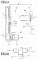
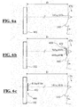
- the FIG. 1 a) 1 shows the schematic structure of a device 100 according to the invention for testing the two polarizing lenses 410a, 410b of a pair of eyeglasses 400.
- the device 100 comprises an imaging device 102.
- the imaging device 102 contains a display device in the form of a display 110 with a plurality of pixels 112a. 112b, 112c, which are controlled via a driver group 120 and a computer unit 150 with memory 152.
- a light source 140 for activating photochromic lenses 410a, 410b provided.
- the schematic drawing of FIG. 1 further shows a subject 170 viewing the display 110 of the imaging device 102 from a distance D.
- the distance D is in the range 30 cm ⁇ D ⁇ 7 m.
- the subject 160 carries on his nose 160 a pair of glasses 400 with two polarizing lenses 410a, 410b. Accordingly, in front of the eyes 161a and 161b of the subject 170 there are polarizing lenses 410a, 410b in a socket 402.
- the display 110 is embodied, for example, as a light-emitting diode matrix display (referred to below as the LED matrix display) or as a liquid-crystal matrix display (referred to below as an LC matrix display).
- a light-emitting diode matrix display referred to below as the LED matrix display
- a liquid-crystal matrix display referred to below as an LC matrix display
- Each pixel 112a, 112b, 112c of the display 110 has a clearly defined polarization plane. There are various possibilities for determining the polarization plane of each pixel 112a, 112b, 112c.
- the respective polarization plane of the pixels 112a, 112b, 112c may be implemented in terms of hardware, e.g. be specified by means of appropriate polarizing films.
- groups of pixels 112a, 112c have the same defined polarization plane.
- the intensities of each of the pixels 112a, 112b, 112c are set via the driver group 120 and the computer unit 150.
- the definition of the plane of polarization of pixels 111 can alternatively also be predefined by the driver group 120 and the computer unit 150. This is possible, for example, in so-called dual stack LC displays. Via the driver group 120 and the computer unit 150, the intensities and the plane of polarization of each individual pixel 112a, 112b, 112c are set.
- the polarization plane of the pixels 112a, 112b, 112c can be changed in an angle range between 0 ° and 90 °.
- two images 114, 116 are stored with the same motif 122.
- a polarization direction is stored, wherein the polarization direction of the one image 114 deviates from the polarization direction of the other image 116.
- Storing a direction of polarization means the storage of retrievable information for displaying the images 114, 116 with linearly polarized light of predetermined polarization direction. This includes the case that the respective images 114, 116 are output via the pixels of a display, which are equipped with a filter whose polarization axis corresponds to the associated polarization direction.
- the two images 114, 116 are superimposed on one another as a display image 118 in such a way that the motif 122a of the first image 114 and the motif 122b of the second image 116 coincide identically to form the motif 122, such as this in FIG. 1 b) simplified is shown schematically.
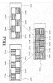
- the first image 210 consists of the pixels 210a, 210b, 210c, 210d, 210e with a first defined polarization plane.
- This defined polarization plane can, for example, occupy 90 ° to the horizontal, that is to say have a vertical orientation. It is also possible that the defined polarization plane occupies, for example, 45 ° to the horizontal.
- the second image 220 consists of the pixels 220a, 220b, 220c, 220d, 220e with a second defined polarization plane.
- the first and the second defined polarization plane can form an angle of 90 °. It is possible that the second defined polarization plane occupies, for example, 0 ° to the horizontal, that is, has a horizontal orientation. It is also possible that the second polarization plane occupies, for example, 135 ° to the horizontal.
- FIG. 2 FIG. 12 also shows an example of a superimposed polarized image 230 which comprises both the image 210 with pixels 210a, 210b, 210c, 210d, 210e having a first defined polarization plane and the image 220 with pixels 220a, 220b, 220c, 220d, 220e a second defined polarization plane exists.
- the FIG. 3 shows a second variant for the arrangement of polarizing pixels.
- the first image 310 consists of the pixels 310a, 310b, 310c, 310d, 310e, 310f, 310g, 310h, 310i, 310k having a first defined polarization direction and intensity. This defined Polarization direction is vertical in the embodiment.
- the second image 320 consists of the pixels 320a, 320b, 320c, 320d, 320e, 320f, 320g, 320h, 320i, 320k with a second defined polarization direction and intensity.
- the first and second defined directions of polarization enclose an angle of 90 °. In both cases different orientations are possible.
- the superposition of the two images 310 and 320 to the displayed image 330 is effected pointwise by vector addition of the electric field vector, which intensity (magnitude) and polarization direction of the respective pixels 330a, 330b, 330c, 330d, 330e, 330f, 330g, 330h, 330i, 330k outgoing light taken into account.
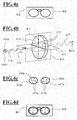
- FIG. 4 shows the structure of polarizing spectacle lenses 400.
- polarizing lenses 410, 410a, 410b are installed ( FIGS. 4b ), 4c)).
- Unpolarized light 416 strikes a polarizing lens 410 as shown in FIG. 4b ), only a portion 417 is transmitted, and (except for reflection and absorption losses) that part of the electromagnetic radiation of the incident light 416 whose polarization direction 416a coincides with the polarization axis 411 of the spectacle lens 414.
- the polarization direction of the transmitted light 417 is indicated in the drawing by the reference numeral 417a.
- the portion of the electromagnetic radiation of the incident light 416 whose polarization direction 416b does not coincide with the polarization axis 411 of the spectacle lens 414 is either reflected or absorbed.
- the transmission plane 414 of the polarizing spectacle lens 410 is a plane that intersects the spectacle lens 410 and in which the propagation direction 418 of the transmitted radiation 417 is included and which is parallel to the orientation 416a of the maximum transmission of the electrical vector of the transmitted radiation.
- the transmission plane 414 may therefore include the polarization axis 411.
- the normal plane to the transmission plane 414 is called the polarization plane 413 and is identified by markings 412 on the spectacle lens 410.
- Polarizing spectacle lenses 410, 410a, 410b are thus characterized in that they have a defined polarization axis 411, 411a, 411b, as shown in FIG Figure 4c ) yet once illustrated graphically.
- polarizing lenses 410a, 410b By incorporating polarizing lenses 410a, 410b in a socket 400, the location of the polarization axes 411a, 411b and the polarization planes optionally designated by the markers 412a, 412b are defined relative to the socket horizontal 401.
- spectacle lenses are shown in a socket 420 with defined polarization axes 411a, 411b of 90 ° each (vertical orientation).
- the polarization planes optionally marked by the markings 412a, 412b are aligned horizontally in the frame's coordinate system, ie parallel to the frame horizontal 401. This alignment is desirable, for example, with sunglasses, in order to minimize reflections from horizontal surfaces.
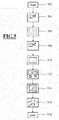
- FIG. 5 shows a method for demonstrating the visual impression for a wearer of spectacles with polarizing spectacle lenses in a schematic representation:
- the starting point is first of all the search for a suitable motif by means of which the wearer should be made aware of the effect of polarizing glasses (not in FIG. 5 shown 502).
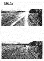
- the FIG. 7 shows a selection of motifs for images that are considered by the inventor to be particularly suitable, because they can simulate a visual impression under natural environmental conditions.
- On the left is an image of an object or a landscape, how the object or the landscape is perceived by the direct observer with the naked eye, and on the right a picture of the object or the landscape, how the observer sees the object or the landscape, if he is a polarizing one Wearing glasses as intended.
- a photographic image of a camera with an upstream polarization filter having a first polarization axis is made.
- the polarization axis runs in the illustrated example in the vertical direction.
- the storage of the image of the camera is shown in step 506.
- a photograph is taken of the subject with an upstream polarization filter but with a second polarization axis deviating from the first polarization axis.
- the second polarization axis runs in the illustrated example in the horizontal direction.
- the storage of the second image of the camera is shown in step 508.
- the first image is provided together with the associated first polarization direction and the second image together with the associated second polarization direction.
- the first image is displayed with light polarized in the first polarization direction and the second image with light polarized in the second polarization direction superimposed so that the motif of the first image and the motif of the second image coincide in identical shape.
- a subject 170 a potential wearer of polarizing glasses
- the carrier 170 is positioned so that it can view the displayed images in superimposed representation optionally with the naked eye 161a, 161b and / or through glasses with non-polarizing spectacle lenses and / or through the spectacles 400 with the polarizing spectacle lenses 410a, 410b ,
- FIG. 6 shows this process in a schematic representation.
- no polarizing element such as polarizing lenses in a socket, is positioned between the eyes 161a, 161b of the subject 160 and the imaging device 100. It is perceived a superposition of images.
- a difference in the intensities of the images is perceived at different defined first and second polarization planes of images.
- This difference in intensities can be used to compare between different polarizing lenses in a socket. In particular, it can be examined whether spectacle lenses in the version have polarizing properties.
- FIG. 6b shows the case where the glasses 400 including the polarizing lenses 410a, 410b are placed in the socket 402 in close proximity to the subject 170. Being in close proximity to the subject 170, it is understood that the distance from the subject 170 to the polarizing lenses 410a, 410b is less than 30% of the distance D.
- the polarizing lenses 410a, 410b in the socket 402 may be worn as intended by the subject 170 on the nose 160.
- FIG. 6c shows the case where the polarizing glasses 400 are placed in close proximity to the image forming device 100. In local proximity, it should be noted that the distance of the imaging device 100 to the polarizing lenses in a socket 320 is less than 30% of the distance D. In particular, the polarizing glasses 400 may be placed at a distance of 0 cm to 10 cm to the image forming device 100.
- FIG. 8a shows a first polarized image 210 and a second polarized image 220, as well as the resulting superposed polarized image 230. The first and second polarized images 210, 220 differ in optical properties.
- the first polarized image 210 consists of pixels (eg corresponding to the pixels 210a, 210b, 210c, .. after the FIG. 2 ) having a first defined polarization plane, the polarization plane being vertical.
- the second polarized image 220 consists of pixels (eg 220a, 220b, 220c, ..) with a second defined polarization plane, the polarization plane being horizontal.
- the first image 210 is all over in a first color
- the second image 220 is held over the entire surface in a second color. In this example, the first color is green, the second color is red. If no polarizing element, such as polarizing lenses 410a, 410b in a socket 402, is positioned between the eyes 161a, 161b of the subject 160 and the imaging device 100, then the superimposed polarized image 230 is perceived.
- the superimposed polarized image 230 appears yellow in this first embodiment.
- polarizing lenses 410a, 410b between the eyes 161a, 161b of the subject 160 and the display 110 which, as desired for sunglasses, have a defined polarization axis 411a, 411b of both polarizing lenses 410a, 410b each having 90 ° or each having a horizontally oriented, parallel to a horizontal frame 401 lying polarization plane, which may be marked by markings 412, 412a, 412b, so at high polarization P only the first image 210 is displayed because of this If the polarization plane of the pixels 210a, 210b, 210c of the first image 210 with the polarization axis 411a of the polarized spectacle lenses 410a, 410b are approximately parallel.
- the transmission plane 414 coincides with the plane of polarization of the pixels 210a, 210b, 210c of the first image 210.
- the plane of polarization of the pixels 220a, 220b, 220c of the second image 220 forms an angle of 90 ° with the polarization axis 410a, 410b of the polarized spectacle lenses 410a, 410b or coincides with the polarization plane, so that the second image 220 only has a very low intensity is perceived.
- two form-identical images with an intensity distribution B1 (x, y) and B2 (x, y) are generated in the computer.
- x and y are the index of the column or line on the display
- the function value B1 or B2 at such a point x, y indicates the brightness of a pixel, or in color representation, the brightness of the respective color red, green, and Blue.
- the picture B1 differs only in the optical properties of picture B2.
- image B1 shows diminished reflections, diminished glare or the like.
- a first polarized image 210 is represented by the intensity distribution B1 (x, y) and a second polarized image 220 by the intensity distribution B2 (x, y) -B1 (x, y), the resulting superposed polarized image 230 results an intensity distribution B2 (x, y).
- polarizing element such as polarizing lenses 410a, 410b in a socket 402
- the superimposed polarized image 230 ie the intensity distribution B2 (x, y) perceived.
- polarizing lenses 410a, 410b between the eyes 161a, 161b of the subject 160 and the display 110, which, as desired with sunglasses, have a defined polarization axis 411a, 411b of 90 ° for each of the two polarizing lenses 410a, 410b, respectively one each horizontally oriented, parallel to a frame horizontal 401 lying polarization plane, which may be marked by markings 412, 412a, 412b, so at high polarization degree P only the first image 210, so the intensity distribution B1 (x, y) is displayed as in this case the plane of polarization of the pixels 210a, 210b, 210c of the first image 210 is approximately parallel to the polarization axis 411a of the polarized spectacle lenses 410a, 410b.
- the transmission plane 414 coincides with the plane of polarization of the pixels 210a, 210b, 210c of the first image 210.
- the plane of polarization of the pixels 220a, 220b, 220c of the second image 220 forms an angle of 90 ° with the polarization axis 410a, 410b of the polarized spectacle lenses 410a, 410b or coincides with the polarization plane, so that the second image 220 only has a very low intensity is perceived.
- a direct comparison between different qualities of polarizing spectacle lenses 410a, 410b thus becomes possible.
- the second image 220 is perceived with higher intensity than the first image 210 of the FIG. 8d ).
- FIG. 8e shows an example of a realistic case of visual impression with low-quality polarizing spectacle lenses 410a, 410b as known from many experiments.
- the visual impression is shown by the polarizing lens 410 with a polarization axis 411 a.
- the first polarizing image pattern 210 is still predominantly displayed.
- An overlay of the first and second images 210, 220 can already be seen on the edge of the polarizing spectacle lens 410.
- the color impression is already yellow.
- inhomogeneities of the polarizing spectacle lens 410 can be seen, which are visible in the form of zones with a low degree of polarization 800a, 800b, 800c, 800d.
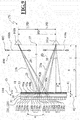
- FIG. 9 shows in conjunction with the Figures 10 and 11 a device 100 with which a three-dimensional visual impression for a viewer 170 can be generated.
- the FIG. 9 is a partial section of the in the FIG. 1 shown arrangement comprising the inventive device 100 and the subject 170 along the line II in FIG. 1 ,
- the display 110 shown includes an array 1230 of a plurality of pixels 210a, 210b, 210c, ... 1210a, 1210b, 1210c, ..., 220a, 220b, 220c, ... 1220a, 1220b, 1220c, are arranged like a checkerboard, like the FIG. 10 extracts in plan view shows.
- Light 25a, 25b which exits the display 110 through the pixels 210a, 210b, 210c, ... 1210a, 1210b, 1210c in the direction of the observer 170, has a linear polarization with a vertical polarization direction.
- Light 25a, 25b which exits the display 110 through the pixels 220a, 220b, 220c,... 1220a, 1220b, 1220c,... Towards the observer 170, has a linear polarization with a horizontal polarization direction.
- the display 110 is equipped in the present embodiment with a diaphragm system forming a parallax mask 37.
- the mask 37 of the diaphragm system 36 is on a transparent support member 38 is arranged.
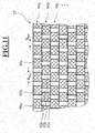
- the FIG. 11 shows a portion of this mask 37 for the diaphragm system in plan view.
- the mask 37 has mutually offset regions 90a, 90b, 90c, ...., which are responsible for the light 25a, 25b of the pixels 210a, 210b, 210c,... 1210a, 1210b, 1210c,..., 220a, 220b , 220c, ... 1220a, 1220b, 1220c, ... of the display 110 are impermeable.
- the regions 92a, 92b, 92c,... Of the mask 37 are complementary to the regions 90a, 90b, 90c, ....
- the regions 92a, 92b, 92c,... permeable For the light 25a, 25b of the display 110, the regions 92a, 92b, 92c,... permeable.
- the regions 90a, 90b, 90c, ... and 92a, 92b, 92c are arranged in successive lines 94. In adjacent lines 94a, 94b; 94b, 94c, the light-transmissive regions 92a, 92b, 92c, ..
- the mask 37 separates the light 25a, 25b for the left and right eye 161a, 161b of the subject 170 in the light passage plane 41.
- the light passage plane 41 of the mask 37 is freely displaceable in the display 110.
- the display 110 includes an adjustment device (not shown) for the diaphragm system. With the adjustment, the diaphragm system according to the in the FIG. 9 shown double arrow 43 are moved in the horizontal direction and in the direction perpendicular to the double arrow 43 horizontal direction.
- the adjusting device contains a piezoelectric drive which can be controlled by the display 150 via a driver assembly by means of the computer 150 as a function of an angular position ⁇ of the eyes 161a, 161b of the subject 170 detected by a camera, not shown.
- the adjustment device makes it possible to increase the distance z of the plane 42 of the display 110 from the light passage plane 41 of the diaphragm 37 in the range 8 mm ⁇ z ⁇ 15 mm vary.
- center 27 of the pupillary distance PD is adjusted with the adjusting the aperture system and tracked that the line 29 through the points 27 and the vertical line 31 behind the aperture 37 on the plane 42 of the Displays 110 the boundary of two adjacent display zones 210a / 220a, 1210a / 1220a, 210b / 1210b ... meets.
- the position of the display zones 210a / 220a, 210b / 1210b ... and the display zones 1210a / 1220a, 1210b / 1220b,... Of the display 110 is adjusted to the displacement of the mask 37.
- S is the offset of the center of the perpendicular projection of the pupil distance PD in the plane 41 of the mask 37 from the surface normal 29 on the vertical line 29.
- g is the distance of the subject 170 from the light passage plane 41 of the diaphragm system.
Landscapes
- Physics & Mathematics (AREA)
- General Physics & Mathematics (AREA)
- Optics & Photonics (AREA)
- Health & Medical Sciences (AREA)
- Ophthalmology & Optometry (AREA)
- Chemical & Material Sciences (AREA)
- Analytical Chemistry (AREA)
- Engineering & Computer Science (AREA)
- General Health & Medical Sciences (AREA)
- Geometry (AREA)
- Computational Mathematics (AREA)
- Mathematical Analysis (AREA)
- Mathematical Optimization (AREA)
- Mathematical Physics (AREA)
- Pure & Applied Mathematics (AREA)
- Business, Economics & Management (AREA)
- Algebra (AREA)
- Educational Administration (AREA)
- Educational Technology (AREA)
- Theoretical Computer Science (AREA)
- Polarising Elements (AREA)
Description
- Die Erfindung betrifft eine Vorrichtung zur Demonstration des Seheindrucks für einen Träger einer Brille mit polarisierenden Brillengläsern nach dem Oberbegriff des Patentanspruchs 1 sowie ein Verfahren zur Demonstration des Seheindrucks für einen Träger einer Brille mit polarisierenden Brillengläsern nach dem Oberbegriff des Patentanspruchs 8.
- Unter Brillengläsern werden im Rahmen der vorliegenden Erfindung alle Arten von optischen Korrekturgläsern oder Korrekturlinsen sowie auch Gläser oder Linsen ohne optische Korrektur verstanden, die Bestandteil einer Brille sind und durch die der Brillenträger bei bestimmungsgemäßem Gebrauch blickt. Es gibt Brillengläser aus Kunststoff und solche aus Mineralglas.
- Polarisation beschreibt die Richtung einer Schwingung einer elektromagnetischen Welle. Natürliches Licht wird meist unpolarisiert als Überlagerung von verschiedenen Wellen von elektromagnetischer Strahlung mit unterschiedlicher Schwingungsebene und -phase wahrgenommen. Nach Reflexion an einer Grenzfläche weist das reflektierte Licht teilweise eine Polarisationsrichtung auf.
- Ein polarisierendes Brillenglas ist in der DIN EN ISO 13666 (1998) definiert als ein Brillenglas, das unterschiedliche Lichtabsorption in Abhängigkeit von der Polarisation des auftreffenden Lichtes besitzt. Die Orientierung der maximalen Transmission des elektrischen Feldvektors der elektromagnetischen Strahlung durch ein polarisierendes Brillenglas wird als Polarisationsachse des Brillenglases bezeichnet. Die Lage der Polarisationsachse in der Fassung wird in Grad (°) angegeben, wobei 0° eine horizontale Ausrichtung und 90° eine vertikale Ausrichtung der Polarisationsachse beschreibt. Die Transmissionsebene eines polarisierenden Brillenglases ist definiert als eine das Brillenglas schneidende Ebene, in der die Ausbreitungsrichtung der übertragenen Strahlung enthalten ist und die parallel zur Orientierung der maximalen Transmission des elektrischen Feldvektors der übertragenen Strahlung ist. Die Polarisationsebene eines polarisierenden Brillenglases ist normal zur Transmissionsebene und wird oft durch Markierungen auf einem polarisierenden Brillenglas gekennzeichnet. Ein Aufbau zur Bestimmung der Polarisationsebene wird beispielsweise in der DIN EN ISO 8980-3:2004 oder den DIN EN 1836:2005+A1:2007 (D) gezeigt.
- Es gibt Brillengläser, die dauerhaft eine vorzugsweise vorbestimmte polarisierende Eigenschaft besitzen und solche, bei denen sich die polarisierende Eigenschaft ändern kann. Zu letzteren zählen auch sogenannte phototrope Brillengläser. Bestandteil derartiger Brillengläser ist ein phototropes Material z.B. in Form einer Beschichtung oder in Form von Zusätzen zum Brillenglaskörper. Ein phototropes Material ist ein Material, das seine Lichttransmissionseigenschaften reversibel in Abhängigkeit von der Bestrahlungsstärke und den Wellenlängen der auftreffenden Strahlung ändert. Dabei kann die Veränderung der Lichttransmissionseigenschaften rein die Absorption verändern oder aber auch einen polarisierenden Effekt erzeugen.
- Bei einer polarisierenden Brille sind die zwei polarisierenden Brillengläser in einer Fassung fest eingebaut. Darunter ist zu verstehen, dass zwischen der Fassung und den Brillengläsern eine mechanisch feste Verbindung besteht. Es können also zur Fixierung der Brillengläser sowohl Vollrandfassungen, Tragrandfassungen, Rimfassungen als auch randlose Fassungen vorgesehen sein.
- Polarisierende Brillengläser finden hauptsächlich Verwendung in Sonnenbrillen. Bei derartigen polarisierenden Brillengläsern, welche die Blendung durch die Sonne reduzieren sollen, ist die Transmissionsebene aus den nachfolgenden Gründen normalerweise vertikal und die Polarisationsebene horizontal orientiert.
- Bekanntlich ist der sogenannte Brewster Winkel der Winkel zur Normalen einer Grenzfläche, bei welchem einfallendes Licht so reflektiert wird, dass nur die parallel zur Grenzfläche (also senkrecht zur Einfallsebene) polarisierten Anteile reflektiert werden (s-polarisiert). Bei einer horizontalen Grenzfläche (wie beispielsweise bei einer Wasseroberfläche) ist unter diesem Winkel reflektiertes Licht daher horizontal polarisiert. Unter anderen, vom Brewster Winkel abweichenden Winkeln, hat das reflektierte Licht zusätzlich in der Einfallsebene liegende polarisierte Anteile (p-polarisiert). Bei einer polarisierenden Brille wie beispielsweise einer Sonnenbrille mit polarisierenden Brillengläsern ist die Polarisationsachse vertikal (90°) orientiert und die Polarisationsebene ist horizontal (0°) orientiert. Brillengläser mit vertikaler Polarisationsachse oder horizontaler Polarisationsebene sind also für vertikal polarisiertes Licht durchlässig. Damit sind Reflexionen auf horizontalen Flächen (wie beispielsweise Wasseroberflächen) für den Brillenträger stark reduziert.
- Polarisierende Brillen bestehen aus zwei polarisierenden Brillengläsern, welche fest in einer Fassung eingebaut sind, wobei die beiden definierten Polarisationsebenen der beiden polarisierenden Brillengläser nach der DIN EN 1836:2005+A1:2007 nicht mehr als 6° voneinander abweichen dürfen.
- Die DIN EN 1836:2005+A1:2007 (D) sieht ferner vor, dass die Polarisationsebene bei Sonnenbrillen um nicht mehr als +/-5° von der Horizontalen abweichen darf. Das bedeutet, dass polarisierende Brillengläser so in der Fassung eingebaut sein müssen, dass deren Polarisationsachse um nicht mehr als +/-5° von der Vertikalen abweichen. Solche Sonnenbrillen sind beispielsweise in der
US 747,235 beschrieben. - Der Polarisationsgrad oder die Polarisationseffizienz quantifizieren die Güte der Polarisation eines Brillenglases. Die Begriffe Polarisationsgrad und Polarisationseffizienz werden in der Literatur oft als äquivalent angesehen. Der Polarisationsgrad und die Polarisationseffizienz werden in der DIN EN 1836 und der DIN EN ISO 13666 definiert. Der Polarisationsgrad P ist definiert als P=(Imax-Imin)/(Imax+Imin), wobei Imax und Imin die Extremwerte des Lichttransmissionsgrades I bezeichnen. Zur Ermittlung des Polarisationsgrades wird das polarisierende Brillenglas auf einer Seite mit 100 % linear polarisiertem Licht mit einer definierten Polarisationsebene und mit einer Intensität bestrahlt. Auf der gegenüberliegenden Seite des polarisierenden Brillenglases kann die Intensität abhängig von der Winkelstellung des polarisierenden Brillenglases relativ zur definierten Polarisationsebene gemessen werden. Für einen bestimmten Winkel wird der Maximalwert Imax des Lichttransmissionsgrades I ein Maximum erreichen. Diesen Winkel bezeichnet die Polarisationsachse. Bei dieser Winkelstellung ist jede zur definierten Polarisationsebene des einfallenden Lichts parallele Ebene eine Transmissionsebene des polarisierenden Brillenglases. Bei einem anderen Winkel tritt der Minimalwert Imin des Lichttransmissionsgrades I auf. Imin tritt meist bei einem zur Polarisationsachse um 90° abweichenden Winkel auf. Bei dieser Winkelstellung ist jede zur definierten Polarisationsebene des einfallenden Lichts parallele Ebene eine Polarisationsebene des polarisierenden Brillenglases. Auch die Angabe des Polarisationsverhältnisses R=Imax/Imin kann zu Beurteilung der Qualität von polarisierenden Brillengläsern verwendet werden.
- Polarisierende Brillengläser müssen gemäß DIN EN 1836:2005+A1:2007 (D) und DIN EN ISO 8980-3:2004 ein Verhältnis zwischen maximaler und minimaler Lichttransmission größer als 8:1 bzw. größer als 4:1 aufweisen. Polarisierende Brillengläser erreichen damit einen Polarisationsgrad von 78 % bzw. 60 %. Qualitativ hochwertige Gläser haben einen Polarisationsgrad von mehr als 99%.
- Derartige Kennzahlen sind jedoch für einen Brillenträger nur schwer fassbare Größen. Ohne eigene Vergleichs- oder Erfahrungswerte oder ohne Kenntnis der Bedeutung der Kennzahlen ist es für den Brillenträger in der Regel kaum möglich qualitativ hochwertige Brillengläser von qualitativ minderwertigeren Brillengläsern zu unterscheiden.
- Zur Demonstration der polarisierenden Eigenschaft von z.B. Sonnenbrillen mit polarisierenden Brillengläsern werden daher heute oft Aufkleber oder kleine Embleme verwendet, welche Licht mit einer definierten Polarisationsrichtung reflektieren. Dabei kann der Brillenträger durch polarisierende Brillengläser die Aufkleber oder Embleme betrachten. Wenn die Aufkleber oder Embleme relativ zu den polarisierenden Brillengläser in einer Fassung rotiert werden, so ist eine Intensitätsänderung bemerkbar, welche bei nicht polarisierenden Brillengläsern nicht auftritt. Damit kann jedoch keinerlei Aussage über die Qualität polarisierender Brillengläser in einer Fassung getroffen werden, sondern nur eine einfache Unterscheidung zwischen polarisierenden Brillengläsern in einer Fassung und nicht polarisierenden Brillengläsern in einer Fassung.
- Weitere Demonstratoren beruhen darauf, dass einem Testbild mittels halbdurchlässiger Folie eine simulierte Reflexion überlagert wird. Bei Betrachtung des Demonstrators durch eine polarisierende Brille wird die simulierte Reflexion in ihrer Intensität stark verringert und das ursprüngliche Bild ist mit erhöhtem Kontrast zu sehen. Auch hier ist keine Unterscheidung der Qualität möglich. Außerdem zeigt diese Art von Demonstratoren nur ein einzelnes Testbild, welches gegebenenfalls nicht den Gebrauchsbedingungen des Brillenträgers entspricht.
- Aus dem Stand der Technik sind ferner Sehprüfgeräte bekannt, die mit Hilfe von Sehzeichentafeln oder Displays Sehzeichen mit polarisiertem Licht unterschiedlicher Polarisationsrichtung anzeigen. Bei bestimmungsgemäßem Gebrauch trägt ein Proband eine Brille mit zwei unterschiedlich polarisierten Brillengläsern, wobei die Polarisationsachsen der beiden Brillengläser senkrecht aufeinander stehen. Damit wird erreicht, dass der Proband ein angezeigtes Sehzeichen oder Teile davon nur mit einem Auge und andere Teile nur mit dem anderen Auge wahrnehmen kann.
- Ein derartiges Sehprüfgerät ist beispielsweise aus der
EP 0 512 443 A1 bekannt. Das Sehprüfgerät besteht im Wesentlichen aus zwei Polarisationsfolien und zwei Flüssigkristall-Displays, welche alternierend angeordnet sind. Diese Anordnung ist in der Lage, das von einer Lichtquelle kommende Licht so zu beeinflussen, dass Sehzeichen oder Teile davon gezielt nur von einem Auge oder aber von beiden Augen gesehen werden können. Die Lichtquelle beleuchtet mit ihrem Licht zunächst die erste farbneutrale, durchsichtige Polarisationsfolie. Das durch die erste Polarisationsfolie fallende Licht durchdringt das erste ggf. farbige Display und beleuchtet die zweite, farbneutrale Polarisationsfolie. Das durch die zweite Polarisationsfolie fallende Licht durchdringt das zweite Display, wonach das Licht das Sehprüfgerät verlässt. Mit einem derartigen Sehprüfgerät kann man nun Figuren und Zeichnungen darstellen, indem man die einzelnen Flüssigkristallzellen antreibt. Soll das dargestellte Sehzeichen verändert werden, so erfolgt ein entsprechender Befehl über eine Tastatur an eine Schalteinrichtung, welche in gewünschter Art und Weise die beiden Treiberschaltungen der beiden Displays ansteuert. - Die
EP 0 595 023 A1 beschreibt ein Sehprüfgerät im wesentlichen bestehend aus mindestens einem Vektographenfilm mit vielen einzelnen Polarisationselementen und mindestens einem Bildschirm. Die Polarisationselemente sind streifenförmig angeordnet, wobei die Polarisationselemente eines Streifens dieselbe Polarisationsrichtung besitzen. Die Polarisationselemente in den nebeneinander angeordneten Streifen haben aufeinander senkrecht stehende Polarisationsachsen. Explizit angemerkt wird in der Veröffentlichung, dass die Flüssigkeitskristall-Displays normalerweise aus mehreren hundertmal mehrere hundert LCD-Elementen bestehen, so dass bei genügend großem Abstand des Betrachters vom Display keine Streifen sichtbar sind. - Die
DE 199 47 775 A1 beschreibt eine Testeinrichtung ähnlich der in derEP 0 595 023 A1 beschriebenen Art. Den Augen des Probanden werden waagerechte - übereinander angeordnete Zeilenpaare dargeboten, wobei durch die Testeinrichtung jeweils nur eine Zeile für das eine Auge und die andere Zeile für das andere Auge bereitgestellt wird. - Die
DE 100 07 020 A1 betrifft ein Nahsehprüfgerät zur Anzeige von Sehzeichentafeln. Auf jeder Sehzeichentafel ist ein bzw. sind mehrere Sehzeichen zur Prüfung der Sehfähigkeit des Benutzers angeordnet. Eine Sehzeichentafel zeigt einen Stereotest, durch den die räumliche Wahrnehmung des Probanden überprüft wird. Aufgrund der horizontal versetzten, unterschiedlich polarisierten Dreiecke erscheinen diese zu einem in der Mitte der Sehzeichentafel angeordneten, schwarz dargestellten und für beide Augen wahrnehmbaren Punkt räumlich versetzt. - Diese Sehprüfgeräte sind konzipiert für Brillen mit polarisierenden Brillengläsern, deren Polarisationsachsen einen von Null verschiedenen Winkel, üblicherweise einen 90°-Winkel, einschließen. Ein mit dem Display des jeweiligen Sehprüfgeräts gerade angezeigtes Sehzeichen kann zwar beim Träger einer Brille mit polarisierten Brillengläsern mit parallel ausgerichteten Polarisationsachsen in Abhängigkeit von der Güte der Polarisationseigenschaften einen anderen Seheindruck hervorrufen, der Brillenträger kann jedoch im allgemeinen anhand des Seheindrucks nicht beurteilen, ob er eine qualitativ hochwertige oder eine minderwertige Brille trägt.
- Die
US 2006/0203338 A1 , von der die Erfindung ausgeht, beschreibt ein gestapeltes Display zur Darstellung von dreidimensionalen Bildern und Videos. Es werden zwei überlagerte, polarisierte Bildmuster erzeugt, welche sich durch unterschiedliche Polarisationsebenen unterscheiden. Die zwei Bildmuster rufen durch zeitgleiches Betrachten durch eine Brille mit polarisierten Brillengläsern mit um 90° unterschiedlichen Polarisationsachsen beim Betrachter einen dreidimensionalen Seheindruck hervor. Ein dreidimensionaler Seheindruck lässt sich nur erzeugen, wenn die beiden Bildmuster einen Gegenstand aus unterschiedlichen Perspektiven zeigen. Die beiden Bildmuster sind also nicht deckungsgleich. Die Motive der beiden Bildmuster sind also nicht identisch. Betrachtet man das Display mit einer Brille mit polarisierten Brillengläsern mit parallel zueinander ausgerichteten Polarisationsachsen, so nimmt man entweder nur eines der beiden Bildmuster mit einem der beiden Augen wahr und zwar dann, wenn die Polarisationsrichtung des Lichts von diesem Bildmuster gerade mit der Orientierung der Polarisationsachse der Brillengläser zusammenfällt, oder man nimmt beide Bildmuster mit beiden Augen gleichzeitig wahr, was einen verschwommenen Seheindruck hervorruft, weil die beiden Motive nicht identisch und nicht deckungsgleich sind. Eine Aussage über die Güte der polarisierten Brille ist nicht möglich. - Aufgabe der Erfindung ist es, eine Vorrichtung und ein Verfahren zur Demonstration des Seheindrucks für einen Träger einer Brille mit polarisierenden Brillengläsern bereitzustellen, mit dem die Qualität und Funktionalität der polarisierenden Brille sowohl für den Käufer als auch den Verkäufer überprüft werden kann.
- Diese Aufgabe wird durch eine Vorrichtung mit den Merkmalen des Patentanspruchs 1 sowie durch ein Verfahren mit den Merkmalen des Patentanspruchs 8 gelöst.
- Vorteilhafte Ausführungen und Weiterbildungen der Erfindung sind Gegenstand der Unteransprüche.
- Die erfindungsgemäße Vorrichtung zur Demonstration des Seheindrucks für einen Träger einer Brille mit polarisierenden Brillengläsern umfasst einen Speicher zum Bereitstellen eines ersten Bildes mit einem Motiv und einer zugehörigen ersten Polarisationsrichtung, einen Speicher zum Bereitstellen eines zweiten Bildes mit einem Motiv und einer zugehörigen zweiten von der ersten Polarisationsrichtung verschiedenen Polarisationsrichtung sowie eine Anzeigeeinrichtung zum Anzeigen des ersten Bildes mit in der ersten Polarisationsrichtung polarisiertem Licht und des zweiten Bildes mit in der zweiten Polarisationsrichtung polarisiertem Licht in überlagerter Darstellung. Erfindungsgemäß handelt es sich bei den beiden Motiven des ersten und zweiten Bildes um dasselbe Motiv. Abweichend von der in der
US 2006/0203338 A1 beschriebenen Vorrichtung erfolgt die Anzeige des ersten Bildes und des zweiten Bildes so, dass das Motiv des ersten Bildes und das Motiv des zweiten Bildes formidentisch zusammenfallen. Die beiden Motive des ersten und zweiten Bildes stimmen also in ihrer Größe und Form überein und sind weder in für den Betrachter wahrnehmbarer Weise in lateraler Richtung noch in der Tiefe versetzt. - Der Begriff "Überlagerung" bedeutet auch, dass die Bilder für den Betrachter gleichzeitig wahrgenommen werden oder anders ausgedrückt, dass der Betrachter nicht den Eindruck hat, diese würden ihm nacheinander angezeigt. Dies bedeutet, dass jedes der polarisierten Bildmuster zumindest zehn Mal pro Sekunde dargestellt wird, wobei diese Anzeige der Einzelbilder durchaus im Wechsel erfolgen kann, solange das menschliche Auge diesen Umstand nicht zu erkennen vermag.
- Ein Betrachter nimmt die beiden deckungsgleichen Motive mit bloßem Auge als ein einziges Motiv wahr. Trägt der Betrachter eine polarisierende Brille mit zwei Brillengläsern identischer Polarisationsachse in bestimmungsgemäßer Weise, so nimmt er die Bilder nur insoweit wahr, als diese polarisierte Anteile aufweisen, die mit der Polarisationsachse der Brillengläser zusammenfallen. Damit ist es möglich, durch geeignete Wahl des Motivs und der Polarisationsrichtungen der beiden Bilder beim Betrachter der Anzeigeeinrichtung einen Seheindruck zu erzeugen, der dem entspricht, den er hätte, wenn er das Motiv nicht als Abbild auf der Anzeigeeinrichtung sehen würde, sondern im Original z.B. als tatsächlich existierenden Gegenstand oder in Form einer Landschaft mit und ggf. ohne Verwendung einer polarisierenden Brille.
- Es sei hiermit ausdrücklich klargestellt, dass der Begriff "Motiv" im Sinne von Bildmotiv zu verstehen ist, nämlich als der wesentliche inhaltliche Bestandteil eines Bildes wie z.B. einer Fotographie oder einer Graphik. Die Betonung liegt auf einem zentral dargestellten Objekt (Person, Gebäude, Teil einer Landschaft oder Situation).
- Besonders eindrucksvoll lässt sich einem Betrachter die Wirkung einer polarisierenden Brille zeigen, wenn ihm ein seiner natürlichen Umgebung entsprechendes Motiv dargeboten wird. Ein derartiges Motiv kann z.B. eine sich aus dem Meer erhebende Insel bei klarem Himmel und strahlender Sonne sein. Ein Betrachter wird mit bloßem Auge starke Reflexionen des Sonnenlichts an der Wasseroberfläche wahrnehmen. Trägt der Betrachter eine polarisierende Sonnenbrille werden diese Reflexionen für ihn unsichtbar und er kann bei hinreichend klarem Wasser sogar auf den Grund sehen. Ziel der Erfindung ist es, insbesondere diese natürliche Situation für den Betrachter auf der Anzeigeeinrichtung künstlich nachzubilden.
- Grundsätzlich ist es möglich, das vorstehend genannte Motiv und die beiden Bilder mit zugeordneter unterschiedlicher Polarisationsrichtung künstlich z.B. in Form einer Computergraphik zu erzeugen. Ein der Realität im Allgemeinen näher kommender Seheindruck lässt sich erzeugen, wenn das erste Bild eine fotographische Aufnahme einer Kamera mit vorgeschaltetem Polarisationsfilter mit einer ersten Polarisationsachse ist und wenn das zweite Bild ebenfalls eine fotographische Aufnahme einer Kamera mit vorgeschaltetem Polarisationsfilter mit einer zweiten von der ersten Polarisationsachse verschiedenen Polarisationsachse ist. Selbstverständlich ist es auch möglich, wenn nur eines der Bilder eine entsprechende fotographische Kameraaufnahme ist und das andere Bild z.B. aus einer entsprechende Modifikation des einen Bildes mit Hilfe eines Computers erzeugt wird. Um die erfindungsgemäße Formidentität der Motive in beiden Bildern zu erhalten, ist es im ersten Fall natürlich günstig, wenn die beiden fotographischen Aufnahmen von ein und derselben Kamera gemacht werden und wenn deren Einstellungen unverändert beibehalten werden. Auch die Aufnahmerichtung und Entfernung zum Objekt ist selbstverständlich vorzugsweise identisch bei beiden Aufnahmen zu wählen.
- Es ist ferner möglich, bewegliche Motive, also beispielsweise in Form eines Videos mit einer fortlaufenden Sequenz an Bildern der vorstehend beschriebenen Art darzustellen. Ein derartiges bewegliches Motiv kann z.B. durch eine bewegte Kamera erzeugt werden. Insbesondere kann damit eine Folge von verschiedenen Betrachtungssituationen zeitlich nacheinander demonstriert werden.
- Um die erfindungsgemäß erforderliche Formidentität der Motive in beiden Bildsequenzen zu erhalten, ist es natürlich günstig, wenn die beiden einander entsprechenden Videoaufnahmen gleichzeitig von zwei Videokameras mit jeweils vorgeschalteten Polarisationsfiltern mit jeweils unterschiedlich ausgerichteten Polarisationsachsen gemacht werden und wenn deren Einstellungen identisch gewählt sind. Auch die Aufnahmerichtung und Entfernung zum Objekt ist selbstverständlich vorzugsweise gleich bei beiden Videoaufnahmen zu wählen, was durch eine mechanische Verbindung der zwei Videokameras sowie starrer Ausrichtung auf dasselbe Motiv erfolgt.
- Eine Alternative zur Verwendung zweier (Video-)Kameras oder einer (Video-)Kamera mit (fortlaufend sequentiell) im Wechsel erfolgender (Video-)Bildaufnahme mit Polarisationsfilter mit einer ersten Polarisationsachsausrichtung und mit Polarisationsfilter mit einer von der ersten Ausrichtung der Polarisationsachse abweichender zweiten Ausrichtung der Polarisationsachse kann auch eine einzige (Video-)Kamera zum Einsatz kommen, welcher ein Polarisationsfilter vorgeschaltet ist, der lokal unterschiedlich ausgerichtete Polarisationsachsen aufweist. Anders ausgedrückt weist das Polarisationsfilter an verschiedenen Stellen eine Polarisationsachse auf, die in eine erste Richtung ausgerichtet ist und an anderen Stellen eine Polarisationsachse, die in eine andere, von der ersten Richtung abweichende Richtung ausgerichtet ist. Diese Stellen mit unterschiedlicher Polarisationsachsausrichtung können z.B. entsprechend der hellen und dunklen Felder eines Schachbretts (d.h. helles Feld = Filterwirkung mit erster Polarisationsachsrichtung und dunkles Feld = Filterwirkung mit zweiter Polarisationsachsrichtung) oder streifenartig im Wechsel angeordnet sein.
- Um einem Betrachter die Wirkung einer polarisierenden Brille zu demonstrieren, wäre es grundsätzlich möglich, als erstes und zweites Bild exakt dasselbe Bild zu verwenden, weil sich die Helligkeit mit der polarisierenden Brille gegenüber einer Betrachtung mit bloßem Auge verringert. Der Unterschied des Seheindrucks mit und ohne polarisierender Brille lässt sich jedoch besonders gut zeigen, wenn sich das erste Bild und das zweite Bild in wenigstens einer optischen Eigenschaft, insbesondere in wenigstens einer der optischen Eigenschaften aus der Gruppe Kontrast, Helligkeit, Sättigung und Farbton unterscheiden. Das Wissen über die Maßgeblichkeit dieser Eigenschaften ist insbesondere dann hilfreich, wenn wenigstens eines der beiden Bilder keine unmittelbare fotographische Aufnahme ist, sondern mit Hilfe technischer Hilfsmittel, wie spezielle optische und/oder rechnerische Filter, aus einer fotographischen Aufnahme erzeugt wurde, oder wenn wenigstens eines der beiden Bilder rein mittels computerimplementierten Hilfsmitteln erzeugt wurde.
- Die Unterscheidung der Bilder in den optischen Eigenschaften ist für den Betrachter dann besonders eindrucksvoll, wenn in den Bildern zumindest zehn unterschiedliche Helligkeitswerte und/oder zehn unterschiedliche Farbwerte enthalten sind. Die unterschiedlichen optischen Eigenschaften der dargestellten Bilder äußern sich konkret in der Darstellbarkeit verminderter Reflexe, verminderter Spiegelungen, dunkleres Blau, Sichtbarkeit eines Regenbogens in einem der beiden Bilder. Die unterschiedlichen optischen Eigenschaften umfassen nicht den Bildaufbau oder verschiedene Ansichten oder Blickwinkel eines dreidimensionalen Objektes.
- Es gibt verschiedene Möglichkeiten der Anzeige der beiden Bilder auf der Anzeigeeinrichtung. Dies kann zum einen an der Art der verwendeten Anzeigeeinrichtung und/oder auch an der Aufbereitung der Bilder zu deren Anzeige. Es gibt z.B. Anzeigeeinrichtungen, deren Bildpunkte (Pixel) in der Art der Felder eines Schachbretts angeordnet sind. Es gibt auch Anzeigeeinrichtungen, deren "Bildpunkte" streifenförmig verlaufen. Es gibt Anzeigeeinrichtungen, bei denen die Polarisationsachse einzelner Bildpunkte fest vorgegeben ist. Bei anderen Anzeigeeinrichtungen kann die Polarisationsachse sämtlicher Felder in beliebiger Weise eingestellt werden. Anzeigeeinrichtungen bei denen die Polarisationsachse einzelner Bildpunkte fest vorgegeben ist, können z.B. schachbrettmusterartig mit hellen und dunklen Feldern aufgebaut sein, wobei die den hellen Feldern des Schachbretts entsprechenden Bildpunkte eine Polarisationsachse aufweisen und die den dunklen Feldern entsprechenden Bildpunkte eine andere Polarisationsachse. Bei Anzeigeeinrichtungen mit bildpunktuell einstellbarer Polarisationsachse ist es dann wiederum möglich, diese mit Hilfe einer geeigneten Software in der Art von Anzeigeeinrichtungen mit fest vorgegebenen Polarisationsachse zu betreiben, indem vorbestimmten Bildpunkten stets dieselbe Polarisationsachse zugewiesen wird.
- Unter Bildpunkten mit einer definierten Polarisationsachse sind solche Bildpunkte zu verstehen, welche alle zumindest 80 %, vorzugsweise zumindest 90 %, weiter vorzugsweise mindestens 95 % linear polarisierte Strahlung erzeugen, wobei der elektrische Vektor der Strahlung der Bildpunkte in einer zur Polarisationsebene parallelen Ebene enthalten ist.
- Basierend auf dieser Erkenntnis kann die Anzeigeeinrichtung so eingerichtet sein, dass das angezeigte erste Bild aus ersten in der Art der Felder einer einzigen der Farben eines Schachbrettmusters angeordneten Bildpunkten besteht und dass das angezeigte zweite Bild aus zweiten in der Art der Felder der anderen Farbe des Schachbrettmusters angeordneten Bildpunkten besteht. Diese Anzeige eignet sich besonders für den Fall, wenn das menschliche Auge beim Betrachten die einzelnen Pixel nicht getrennt nebeneinander wahrnimmt, wie z.B. bei einem Computer- oder Fernsehbildschirm.
- Die Anzeigeeinrichtung kann aber auch derart eingerichtet sein, dass das erste Bild aus in der Art aller Felder eines Schachbrettmusters angeordneten Bildpunkten besteht und dass das zweite Bild aus denselben Bildpunkten besteht und dass die jeweiligen angezeigten Bildpunkte die Information des entsprechenden Bildpunktes des ersten Bildes und die Information des entsprechenden Bildpunktes des zweiten Bildes enthält, wobei die Polarisationsrichtung der Vektoraddition der die Intensität berücksichtigenden Polarisationsrichtungsvektoren der entsprechenden Bildpunkte des ersten Bildes und des zweiten Bildes entspricht.
- Grundsätzlich ist es möglich zur erfindungsgemäßen Demonstration in jeglicher Art linear polarisierte Bilder einander überlagert anzuzeigen soweit sich deren Polarisationsrichtungen unterscheiden. In besonders einfacher Weise lässt der polarisierende Effekt von polarisierenden Brillengläsern zeigen, wenn die erste Polarisationsrichtung senkrecht zu der zweiten Polarisationsrichtung ist. Damit lässt sich durch entsprechende Positionierung des Probanden und bekannter Orientierung der Polarisationsachse seiner polarisierender Brille festlegen, welches der beiden Bilder er wahrnimmt und welches nicht.
- Es ist grundsätzlich möglich, die Anzeigeeinrichtung derart auszubilden, dass ein Betrachter einen dreidimensionalen Seheindruck erhält. Die Anzeigeeinrichtung muss dann Bereiche aufweisen, die ausschließlich für das linke Auge des Betrachters sichtbar sind und Bereiche, die ausschließlich für das rechte Auge des Betrachters sichtbar sind. Jeder der Bereiche für sich muss dann zum Anzeigen eines ersten Bildes mit in der ersten Polarisationsrichtung polarisiertem Licht und eines zweiten Bildes mit in der zweiten Polarisationsrichtung polarisiertem Licht in überlagerter Darstellung ausgebildet sein, so dass das Motiv des ersten Bildes und das Motiv des zweiten Bildes formidentisch zusammenfallen. Der dreidimensionale Seheindruck wird dadurch erzeugt, dass die Darstellung des Motivs des ersten Bereichs und des Motivs des zweiten Bereichs nicht formidentisch zusammenfallen.
- Auf dem auf der in dem optischen Strahlengang zu den Augen des Probanden weisenden Seite der Anzeigeeinrichtung ist zu diesem Zweck eine Optikbaugruppe angeordnet, die das von einer ersten Gruppe ausgewählter Bereiche der Anzeigeeinrichtung dem optischen Strahlengang zugeführte Licht von dem Licht trennt, das dem Strahlengang von einer zweiten Gruppe ausgewählter Bereiche der Anzeigeeinrichtung zugeführt ist, um dem linken Auge des Probanden das Licht aus der ersten Gruppe ausgewählter Bereiche der Anzeigeeinrichtung zuzuführen und das Licht aus der zweiten Gruppe ausgewählter Bereiche der Anzeigeeinrichtung zu dem rechten Auge des Probanden zu leiten.
- Die Optikbaugruppe für das Trennen des Lichts der ersten und zweiten Gruppe ausgewählter Bereiche der Anzeigeeinrichtung mit einem als Parallaxebarriere wirkenden Blendensystem auszubilden. Hierfür kann das Blendensystem z.B. als eine Maske mit abwechselnd lichtdurchlässigen und lichtundurchlässigen Bereichen ausgebildet sein.
- Die abwechselnd lichtdurchlässigen und lichtundurchlässigen Bereiche der Maske können eine Schachbrettform oder eine Streifenform haben. Zweckmäßigerweise sind die Schachbrettform der Bildpunkte und die Schachbrett- oder Streifenform der Maske parallel zueinander angeordnet bzw. ausgerichtet.
- Im allgemeinen Teil der Beschreibungseinleitung wurde darauf hingewiesen, dass auch phototrope Brillengläser zu den polarisierenden Brillengläsern zählen. Um die Wirkungsweise derartiger Brillengläser zu demonstrieren, sieht die Erfindung fakultativ eine Lichtquelle zum Aktivieren der phototropen Brillengläsern vor.
- Das erfindungsgemäße Verfahren zur Demonstration des Seheindrucks für einen Träger einer Brille mit polarisierenden Brillengläsern, umfasst die folgenden Schritte:
- a) Bereitstellen eines ersten Bildes mit einem Motiv und einer zugehörigen ersten Polarisationsrichtung
- b) Bereitstellen eines zweiten Bildes mit demselben Motiv und einer zugehörigen zweiten von der ersten Polarisationsrichtung verschiedenen Polarisationsrichtung
- c) Anzeigen des ersten Bildes mit in der ersten Polarisationsrichtung polarisiertem Licht und des zweiten Bildes mit in der zweiten Polarisationsrichtung polarisiertem Licht in überlagerter Darstellung, so dass das Motiv des ersten Bildes und das Motiv des zweiten Bildes formidentisch zusammenfallen.
- Als erstes Bild kann wie oben zur erfindungsgemäßen Vorrichtung bereits ausgeführt wurde eine fotographische Aufnahme einer Kamera mit vorgeschaltetem Polarisationsfilter mit einer ersten Polarisationsachse verwendet werden. Alternativ oder zusätzlich kann auch als zweites Bild eine fotographische Aufnahme einer Kamera mit vorgeschaltetem Polarisationsfilter mit einer zweiten von der ersten Polarisationsachse verschiedenen Polarisationsachse verwendet werden. Diese können z.B. zusammen mit der Information über die Richtung der Polarisationsachse des verwendeten Filters als der jeweiligen zugehörigen Polarisationsrichtung abgespeichert werden. Letzteres ist jedoch nicht zwingend erforderlich. Die bereitgestellte jeweilige zugehörige Polarisationsrichtung kann auch jede andere beliebige Polarisationsrichtung sein. Zur Erzeugung einer möglichst realistischen Anzeige wird jedoch die Richtung der Polarisationsachse und der Polarisationsrichtung zusammenfallen (Die gleiche Orientierung von Aufnahmebild und Anzeigebild wird natürlich vorausgesetzt).
- Bei dem erfindungsgemäßen Verfahren ist es von Vorteil, wenn sich das erste Bild und das zweite Bild in wenigstens einer optischen Eigenschaft, insbesondere in wenigstens einer der optischen Eigenschaften aus der Gruppe Kontrast, Helligkeit, Sättigung und Farbton unterscheiden. Die Gründe wurden oben zu der Beschreibung der erfindungsgemäßen Vorrichtung bereits dargelegt.
- Es ist einerseits möglich, dass das angezeigte erste Bild aus ersten in der Art der Felder einer einzigen der Farben eines Schachbrettmusters angeordneten Bildpunkten besteht und dass das angezeigte zweite Bild aus zweiten in der Art der Felder der anderen Farbe des Schachbrettmusters angeordneten Bildpunkten besteht und es ist weiter möglich, dass das erste Bild aus in der Art der Felder eines Schachbrettmusters angeordneten Bildpunkten besteht und dass das zweite Bild aus denselben Bildpunkten besteht und dass die jeweiligen angezeigten Bildpunkte die Information des entsprechenden Bildpunktes des ersten Bildes und die Information des entsprechenden Bildpunktes des zweiten Bildes enthält, wobei die Polarisationsrichtung der Vektoraddition der die Intensität berücksichtigenden Polarisationsrichtungsvektoren der entsprechenden Bildpunkte des ersten Bildes und des zweiten Bildes entspricht.
- Da eine herkömmliche Sonnenbrille polarisierende Gläser besitzt, deren Polarisationsachse um nicht mehr als +/-5° von der Vertikalen abweichen, ist es günstig, wenn die erste Polarisationsrichtung horizontal und die zweite Polarisationsrichtung vertikal ausgerichtet wird. Die Polarisationsrichtung eines der beiden Bilder entspricht demzufolge der Richtung der Polarisationsachse der Brillengläser und die Polarisationsrichtung des anderen der beiden Bilder steht senkrecht auf dieser Polarisationsachse. Demzufolge nimmt der Brillenträger mit polarisierender Brille nur das eine der Bilder wahr, während er ohne polarisierende Brille beide Bilder in Überlagerung sieht. Bei Betrachtung der Bilderzeugungseinrichtung ohne polarisierende Brillengläser ist die Überlagerung aller polarisierten Bilder sichtbar, da das bloße Auge Licht mit verschiedenen Polarisationsrichtungen nicht unterscheiden kann.
- Das Verfahren nach der Erfindung kann folgenden weiteren Verfahrensschritt umfassen:
- d) Positionieren eines Probanden zum Betrachten der angezeigten Bilder in überlagerter Darstellung wahlweise mit dem bloßen Auge und/oder durch eine Brille mit nicht-polarisierenden Brillengläsern und/oder durch die Brille mit den polarisierenden Brillengläsern.
- Damit werden dem Probanden die unterschiedlichen Seheindrücke mit dem bloßen Auge, durch eine Brille mit nicht-polarisierenden Brillengläsern und durch eine Brille mit den polarisierenden Brillengläsern verdeutlicht und der Proband wird die Vorzüge von polarisierenden Brillengläsern erkennen.
- In diesem Zusammenhang kann dem Probanden auf Nachfrage auch die Funktionsweise und die Wirkung phototroper Brillengläser nahegebracht werden. Es ist daher vorgesehen bei Bedarf eine die phototropen Brillengläser aktivierende Lichtquelle einzuschalten.
- Die Lichtquelle kann z.B. eine UV-Lampe sein. Mittels einer derartigen UV-Lampe, welche geeignet ist, phototrope Brillengläser zu aktivieren, kann z.B. eine phototrope polarisierende Brille für 60 Sekunden mit ultraviolettem Licht bestrahlt werden. Die so bestrahlte phototrope polarisierende Brille zeigt nach Bestrahlung polarisierende Eigenschaften. Eine Testperson kann dann die Qualität dieser Brille überprüfen.
- Unter Umständen ist es sinnvoll, dass die zur Aktivierung geeignete Lampe zumindest ab dem Positionieren eines Probanden dauerhaft leuchtet, sodass eine konstante Aktivierung der phototropen polarisierenden Brillengläser erfolgt.
- Die Erfindung wird nachfolgend anhand der Zeichnung näher beschrieben. Gleiche oder funktionsgleiche Komponenten sind in den Figuren mit identischen Bezugszeichen versehen. Es zeigen:
- Figur 1
- ein Ausführungsbeispiel einer erfindungsgemäßen Vorrichtung mit einem Display zur Demonstration des Seheindrucks für einen Träger einer Brille mit polarisierenden Brillengläsern
- a) Aufbau der Vorrichtung
- b) Bildüberlagerung mit der Vorrichtung
- Figur 2
- eine erste Variante für die Anordnung polarisierender Bildpunkte in dem Display der Vorrichtung nach der
Figur 1 - Figur 3
- eine zweite Variante für die Anordnung polarisierender Bildpunkte in dem Display der Vorrichtung nach der
Figur 1 - Figur 4
- einen prinzipiellen Aufbau von polarisierenden Brillengläsern in einer Brillenfassung
- a) Brille mit Fassung und Brillenglashorizontale
- b) Polarisationswirkung eines polarisierenden Brillenglases in perspektivischer Darstellung
- c) polarisierende Brillengläser mit unterschiedlicher Polarisationsachse
- d) polarisierende Brille mit vertikal polarisierenden Brillengläsern
- Figur 5
- ein schematisches Ablaufdiagramm eines erfindungsgemäßen Verfahrens zur Demonstration des Seheindrucks für einen Träger einer Brille mit polarisierenden Brillengläsern
- Figur 6
- schematische Darstellung der Beurteilung der Güte von polarisierenden Brillengläsern mit einer Vorrichtung nach der
Figur 1 - Figur 7
- eine Auswahl an Motiven für Bilder zur Durchführung des Verfahrens nach der
Figur 5 - a) Straßenverkehrsmotiv:
- Bild oben: Aufnahme mit Polarisationsfilter mit horizontaler Polarisationsachse
- Bild unten: Aufnahme mit Polarisationsfilter mit vertikaler Polarisationsachse
- b) Strandmotiv:
- Bild oben: Aufnahme mit Polarisationsfilter mit horizontaler Polarisationsachse
- Bild unten: Aufnahme mit Polarisationsfilter mit vertikaler Polarisationsachse
- a) Straßenverkehrsmotiv:
- Figur 8
- eine Defekterkennung basierend auf einem einfachen Bildmuster
- a) zwei polarisierende Bilder und überlagertes Bild
- b) sichtbares Bild bei Betrachtung des überlagerten Bildes nach a) mit einem polarisierenden Brillenglas mit vertikaler Polarisationsachse
- c) sichtbares Bild bei Betrachtung des überlagerten Bildes nach a) mit einem polarisierenden Brillenglas mit 45° geneigter Polarisationsachse
- d) sichtbares Bild bei Betrachtung des überlagerten Bildes nach a) mit einem polarisierenden Brillenglas mit horizontaler Polarisationsachse
- e) sichtbares Bild bei Betrachtung des überlagerten Bildes nach a) mit einem polarisierenden Brillenglas mit nicht einheitlicher Polarisationsachse
- Figur 9
- eine Variante für die Anordnung polarisierender Bildpunkte sowie einer Parallaxiermaske in dem Display der Vorrichtung nach der
Figur 1 zur Erzeugung eines dreidimensionalen Seheindrucks - Figur 10
- die Anordnung polarisierender Bildpunkte in dem Display der Vorrichtung des Ausführungsbeispiels nach der
Figur 9 - Figur 11
- die Anordnung durchlässiger und nichtdurchlässiger Bereiche in der Parallaxiermaske des Ausführungsbeispiels nach der
Figur 9 . - Die
Figur 1 a) zeigt den schematischen Aufbau einer erfindungsgemäßen Vorrichtung 100 zum Testen der beiden polarisierenden Brillengläser 410a, 410b einer Brille 400. Die Vorrichtung 100 umfasst eine Bilderzeugungseinrichtung 102. Die Bilderzeugungseinrichtung 102 enthält eine Anzeigeeinrichtung in Form eines Displays 110 mit einer Vielzahl an Bildpunkten 112a, 112b, 112c, die über eine Treibergruppe 120 und eine Rechnereinheit 150 mit Speicher 152 angesteuert werden. Weiterhin ist im Ausführungsbeispiel nach derFigur 1 eine Lichtquelle 140 zum Aktivieren von phototropen Brillengläsern 410a, 410b vorgesehen. - Die Schemazeichnung der
Figur 1 zeigt weiter einen Probanden 170, der das Display 110 der Bilderzeugungseinrichtung 102 aus einem Abstand D betrachtet. Der Abstand D liegt im Bereich 30 cm < D < 7 m. Der Proband 160 trägt auf seiner Nase 160 eine Brille 400 mit zwei polarisierenden Brillengläsern 410a, 410b. Vor den Augen 161a und 161b des Probanden 170 befinden sich demnach polarisierende Brillengläser 410a, 410b in einer Fassung 402. - Das Display 110 ist beispielsweise als Leuchtdiodenmatrix Display (nachfolgend als LED Matrix Display bezeichnet) oder als Flüssigkristallmatrix Display (nachfolgend als LC Matrix Display bezeichnet) ausgeführt.
- Jeder Bildpunkt 112a, 112b, 112c des Displays 110 weist eine eindeutig definierte Polarisationsebene auf. Zur Festlegung der Polarisationsebene eines jeden Bildpunktes 112a, 112b, 112c gibt es verschiedene Möglichkeiten.
- So kann die jeweilige Polarisationsebene der Bildpunkte 112a, 112b, 112c beispielsweise hardwaremäßig, also z.B. mittels entsprechender Polarisationsfolien, vorgegeben sein. Dabei haben vorteilhafterweise Gruppen von Bildpunkten 112a, 112c dieselbe definierte Polarisationsebene. Über die Treibergruppe 120 und die Rechnereinheit 150 werden in diesem Fall die Intensitäten jedes einzelnen der Bildpunkte 112a, 112b, 112c eingestellt.
- Die Definition der Polarisationsebene von Bildpunkten 111 kann alternativ auch durch die Treibergruppe 120 und die Rechnereinheit 150 vorgegeben werden. Dies ist beispielsweise bei sogenannten Dual Stack LC Displays möglich. Über die Treibergruppe 120 und die Rechnereinheit 150 werden dann die Intensitäten und die Polarisationsebene jedes einzelnen der Bildpunkte 112a, 112b, 112c eingestellt.
- Es gibt Displays, bei denen nur eine Wahl zwischen diskreten, fest vorgegebenen Polarisationsebenen besteht. Bei anderen Displays kann die Polarisationsebene der Bildpunkte 112a, 112b, 112c in einem Winkelbereich zwischen 0° und 90° verändert werden.
- In dem Speicher 152 sind zwei Bilder 114, 116 mit demselben Motiv 122 abgespeichert. Zu jedem Bild 114, 116 ist eine Polarisationsrichtung abgespeichert, wobei die Polarisationsrichtung des einen Bildes 114 von der Polarisationsrichtung des anderen Bildes 116 abweicht. Unter Abspeichern einer Polarisationsrichtung versteht man die Hinterlegung einer abrufbaren Information zum Anzeigen der Bilder 114, 116 mit linear polarisiertem Licht vorgegebener Polarisationsrichtung. Dies schließt den Fall ein, dass die jeweiligen Bilder 114, 116 über die Bildpunkte eines Displays ausgegeben werden, die mit einem Filter ausgestattet sind, dessen Polarisationsachse der zugeordneten Polarisationsrichtung entspricht.
- Mit Hilfe des Displays 110 werden nach der Erfindung gleichzeitig die zwei Bilder 114, 116 einander überlagert als Anzeigebild 118 angezeigt und zwar derart, dass das Motiv 122a des ersten Bildes 114 und das Motiv 122b des zweiten Bildes 116 formidentisch das Motiv 122 bildend zusammenfallen, wie dies in
Figur 1 b) vereinfacht schematisch gezeigt ist. - Eine mögliche Anordnung der Bildpunkte zur Anzeige des ersten Bildes 210 und der Bildpunkte zur Anzeige des zweiten Bildes 220 zeigt die
Figur 2 . Das erste Bild 210 besteht aus den Bildpunkten 210a, 210b, 210c, 210d, 210e mit einer ersten definierten Polarisationsebene. Diese definierte Polarisationsebene kann z.B. 90° zur Horizontalen einnehmen, also eine vertikale Ausrichtung aufweisen. Es ist ebenfalls möglich, dass die definierte Polarisationsebene z.B. 45° zur Horizontalen einnimmt. Das zweite Bild 220 besteht aus den Bildpunkten 220a, 220b, 220c, 220d, 220e mit einer zweiten definierten Polarisationsebene. Die erste und die zweite definierte Polarisationsebene können einen Winkel von 90° bilden. Es ist möglich, dass die zweite definierte Polarisationsebene z.B. 0° zur Horizontalen einnimmt, also eine horizontale Ausrichtung aufweist. Es ist ebenfalls möglich, dass die zweite Polarisationsebene z.B. 135° zur Horizontalen einnimmt. -
Figur 2 zeigt außerdem ein Beispiel für ein überlagertes polarisiertes Bild 230, welches sowohl aus dem Bild 210 mit Bildpunkten 210a, 210b, 210c, 210d, 210e mit einer ersten definierten Polarisationsebene sowie aus dem Bild 220 mit Bildpunkten 220a, 220b, 220c, 220d, 220e mit einer zweiten definierten Polarisationsebene besteht. - Die
Figur 3 zeigt eine zweite Variante für die Anordnung polarisierender Bildpunkte. Das erste Bild 310 besteht aus den Bildpunkten 310a, 310b, 310c, 310d, 310e, 310f, 310g, 310h, 310i, 310k mit einer ersten definierten Polarisationsrichtung und Intensität. Diese definierte Polarisationsrichtung ist im Ausführungsbeispiel vertikal. Das zweite Bild 320 besteht aus den Bildpunkten 320a, 320b, 320c, 320d, 320e, 320f, 320g, 320h, 320i, 320k mit einer zweiten definierten Polarisationsrichtung und Intensität. Die erste und die zweite definierte Polarisationsrichtung schließen einen Winkel von 90° ein. In beiden Fällen sind abweichende Orientierungen möglich. - Die Überlagerung der beiden Bilder 310 und 320 zum angezeigten Bild 330 erfolgt punktweise durch Vektoraddition des elektrischen Feldvektors, welcher Intensität (Betrag) und Polarisationsrichtung des von den jeweiligen Bildpunkten 330a, 330b, 330c, 330d, 330e, 330f, 330g, 330h, 330i, 330k ausgehenden Lichts berücksichtigt.
- Die
Figur 4 zeigt den Aufbau von polarisierenden Brillengläsern 400. In eine Fassung 400 (Figur 4a )) mit einer Fassungshorizontalen 401 werden polarisierende Brillengläser 410, 410a, 410b eingebaut (Figuren 4b ), 4c)). Trifft unpolarisiertes Licht 416 auf ein polarisierendes Brillenglas 410, wie dies inFigur 4b ) gezeigt ist, so wird nur ein Teil 417 übertragen und zwar (abgesehen von Reflexions- und Absorptionsverlusten) der Teil der elektromagnetischen Strahlung des auftreffenden Lichts 416, dessen Polarisationsrichtung 416a mit der Polarisationsachse 411 des Brillenglases 414 zusammenfällt. Die Polarisationsrichtung des transmittierten Lichts 417 ist in der Zeichnung mit dem Bezugszeichen 417a gekennzeichnet. Der Teil der elektromagnetischen Strahlung des auftreffenden Lichts 416, dessen Polarisationsrichtung 416b nicht mit der Polarisationsachse 411 des Brillenglases 414 zusammenfällt wird entweder reflektiert oder absorbiert. - Ferner sind in der
Figur 4b ) die Transmissionsebene 414 und die Polarisationsebene 413 eingezeichnet. Die Transmissionsebene 414 des polarisierenden Brillenglases 410 ist eine Ebene, die das Brillenglas 410 schneidet und in der die Ausbreitungsrichtung 418 der übertragenen Strahlung 417 enthalten ist und die parallel zur Orientierung 416a der maximalen Transmission des elektrischen Vektors der übertragenen Strahlung ist. Die Transmissionsebene 414 kann daher die Polarisationsachse 411 beinhalten. Die Normalebene zur Transmissionsebene 414 wird Polarisationsebene 413 genannt und wird durch Markierungen 412 an dem Brillenglas 410 gekennzeichnet. - Polarisierende Brillengläser 410, 410a, 410b sind also dadurch gekennzeichnet, dass diese eine definierte Polarisationsachse 411, 411a, 411b aufweisen, wie dies auch in der
Figur 4c ) noch einmal graphisch verdeutlicht ist. Durch Einbau von polarisierenden Brillengläsern 410a, 410b in eine Fassung 400 wird die Lage der Polarisationsachsen 411a, 411b und der optional durch die Markierungen 412a, 412b gekennzeichneten Polarisationsebenen relativ zur Fassungshorizontalen 401 definiert. InFigur 4d ) sind Brillengläser in einer Fassung 420 mit definierten Polarisationsachsen 411a, 411b von jeweils 90° (vertikale Ausrichtung) gezeigt. Die optional durch die Markierungen 412a, 412b gekennzeichneten Polarisationsebenen sind im Koordinatensystem der Fassung horizontal ausgerichtet, also parallel zu der Fassungshorizontalen 401. Diese Ausrichtung ist gewünscht etwa bei Sonnenbrillen, um Reflektionen von horizontalen Flächen zu minimieren. - Die
Figur 5 zeigt ein Verfahren zur Demonstration des Seheindrucks für einen Träger einer Brille mit polarisierenden Brillengläsern in schematischer Darstellung: - Ausgangspunkt ist zunächst die Suche nach einem geeigneten Motiv anhand dessen dem Träger die Wirkung einer polarisierenden Brille verdeutlicht werden soll (nicht in
Figur 5 dargestellt, 502). DieFigur 7 zeigt eine Auswahl an Motiven für Bilder, die von dem Erfinder als besonders geeignet angesehen werden, weil sie einen Seheindruck unter natürlichen Umgebungsbedingungen simulieren lassen. Dargestellt ist jeweils links ein Bild eines Gegenstands oder einer Landschaft, wie der Gegenstand oder die Landschaft vom unmittelbaren Betrachter mit bloßem Auge wahrgenommen wird und rechts ein Bild des Gegenstands oder der Landschaft, wie der Betrachter den Gegenstand oder die Landschaft sieht, wenn er eine polarisierende Brille bestimmungsgemäß trägt. - Von einem für geeignet befundenen Motiv wird in einem ersten Schritt 504 eine fotographische Aufnahme einer Kamera mit vorgeschaltetem Polarisationsfilter mit einer ersten Polarisationsachse gemacht. Die Polarisationsachse verläuft in dem dargestellten Beispiel in vertikaler Richtung. Das Speichern des Bildes der Kamera ist in Schritt 506 gezeigt. Mit derselben Kamera wird von dem Motiv in einem weiteren Schritt 508 eine fotographische Aufnahme mit vorgeschaltetem Polarisationsfilter aber mit einer zweiten von der ersten Polarisationsachse abweichenden Polarisationsachse gemacht. Die zweite Polarisationsachse verläuft in dem dargestellten Beispiel in horizontaler Richtung. Das Speichern des zweiten Bildes der Kamera ist in Schritt 508 gezeigt.
- In einem nachfolgenden Schritt 512 werden das erste Bild zusammen mit der zugehörigen ersten Polarisationsrichtung und das zweite Bild zusammen mit der zugehörigen zweiten Polarisationsrichtung bereitgestellt. In dem Schritt 514 erfolgt ein Anzeigen des ersten Bildes mit in der ersten Polarisationsrichtung polarisiertem Licht und des zweiten Bildes mit in der zweiten Polarisationsrichtung polarisiertem Licht in überlagerter Darstellung, so dass das Motiv des ersten Bildes und das Motiv des zweiten Bildes formidentisch zusammenfallen.
- In dem nachfolgenden Schritt 516 wird einem Probanden 170, einem potentiellen Träger einer polarisierenden Brille, das angezeigte überlagerte Bild zur Ansicht gezeigt. Der Träger 170 wird so positioniert, dass er die angezeigten Bilder in überlagerter Darstellung wahlweise mit dem bloßen Auge 161a, 161b und/oder durch eine Brille mit nicht-polarisierenden Brillengläsern und/oder durch die Brille 400 mit den polarisierenden Brillengläsern 410a, 410b betrachten kann.
- Die
Figur 6 zeigt diesen Vorgang in schematischer Darstellung. DerFigur 6a entnimmt man die Bilderzeugungseinrichtung 100 aus derFigur 1 , welche von dem Probanden 170 im Abstand D betrachtet wird, wobei zwischen den Augen 161a, 161b des Probanden 160 und der Bilderzeugungseinrichtung 100 keinerlei polarisierendes Element, wie beispielsweise polarisierende Brillengläser in einer Fassung, positioniert ist. Es wird eine Überlagerung der Bilder wahrgenommen. - Bei unterschiedlicher definierter erster und zweiter Polarisationsebene von Bildpunkten 112a, 112b, 112c,... wird ohne polarisierendes Element, wie beispielsweise polarisierende Brillengläser im Strahlengang kein von der Polarisationsachse abhängiger Intensitätsunterschied zwischen dem ersten polarisierten Bild und dem zweiten polarisierten Bild wahrgenommen.
- Wenn sich zwischen den Augen 161a, 161b des Probanden 170 und der Bilderzeugungseinrichtung 100 polarisierende Brillengläser in einer Fassung befinden, so wird bei unterschiedlicher definierter erster und zweiter Polarisationsebene von Bildern ein Unterschied in den Intensitäten der Bilder wahrgenommen. Dieser Unterschied in den Intensitäten kann zu Vergleichen zwischen verschiedenen polarisierenden Brillengläsern in einer Fassung verwendet werden. Insbesondere kann untersucht werden, ob Brillengläser in der Fassung polarisierende Eigenschaften aufweisen.
-
Figur 6b ) zeigt den Fall, dass die Brille 400 umfassend die polarisierenden Brillengläser 410a, 410b in der Fassung 402 in örtlicher Nähe zum Probanden 170 platziert werden. Unter in örtlicher Nähe zum Probanden 170 ist zu verstehen, dass der Abstand vom Probanden 170 zu den polarisierenden Brillengläsern 410a, 410b weniger als 30% des Abstands D beträgt. Insbesondere können die polarisierenden Brillengläser 410a, 410b in der Fassung 402 in bestimmungsgemäßer Weise vom Probanden 170 auf der Nase 160 getragen werden. -
Figur 6c ) zeigt den Fall, dass die polarisierende Brille 400 in örtlicher Nähe zur Bilderzeugungseinrichtung 100 platziert ist. Unter in örtlicher Nähe ist zu versehen, dass der Abstand der Bilderzeugungseinrichtung 100 zu den polarisierenden Brillengläser in einer Fassung 320 weniger als 30% des Abstands D betragen. Insbesondere kann die polarisierende Brille 400 im Abstand von 0 cm bis 10 cm zur Bilderzeugungseinrichtung 100 platziert sein.Figur 8a ) zeigt ein erstes polarisiertes Bild 210 und ein zweites polarisiertes Bild 220, sowie das entstehende überlagerte polarisierte Bild 230. Das erste und zweite polarisierte Bild 210, 220 unterscheiden sich in den optischen Eigenschaften. In diesem Ausführungsbeispiel besteht das erste polarisierte Bild 210 aus Bildpunkten (z.B. entsprechend den Bildpunkten 210a, 210b, 210c,.. nach derFigur 2 ) mit einer ersten definierten Polarisationsebene, wobei die Polarisationsebene vertikal ist. Das zweite polarisierte Bild 220 besteht aus Bildpunkten (z.B. 220a, 220b, 220c,..) mit einer zweiten definierten Polarisationsebene, wobei die Polarisationsebene horizontal ist. Das erste Bild 210 ist vollflächig in einer ersten Farbe, das zweite Bild 220 ist vollflächig in einer zweiten Farbe gehalten. In diesem Beispiel wird als erste Farbe die Farbe Grün gewählt, als zweite Farbe wird die Farbe Rot gewählt. Wenn zwischen den Augen 161a, 161b des Probanden 160 und der Bilderzeugungseinrichtung 100 keinerlei polarisierendes Element, wie beispielsweise polarisierende Brillengläser 410a, 410b in einer Fassung 402, positioniert ist, so wird das überlagerte polarisierte Bild 230 wahrgenommen. - Das überlagerte polarisierte Bild 230 erscheint in diesem ersten Ausführungsbeispiel als Gelb. Wenn sich zwischen den Augen 161a, 161b des Probanden 160 und dem Display 110 polarisierende Brillengläser 410a, 410b befinden, welche wie bei Sonnenbrillen gewünscht, für beide polarisierende Brillengläser 410a, 410b eine definierte Polarisationsachse 411a, 411b von jeweils 90° aufweisen bzw. jeweils eine horizontal ausgerichtete, parallel zu einer Fassungshorizontalen 401 liegende Polarisationsebene aufweisen, welche durch Markierungen 412, 412a, 412b gekennzeichnet sein können, so wird bei hohem Polarisationsgrad P nur das erste Bild 210 zur Anzeige gebracht, da für diesen Fall die Polarisationsebene der Bildpunkte 210a, 210b, 210c des ersten Bildes 210 mit der Polarisationsachse 411 a der polarisierten Brillengläser 410a, 410b annähernd parallel sind. Damit stimmt die Transmissionsebene 414 mit der Polarisationsebene der Bildpunkte 210a, 210b, 210c des ersten Bildes 210 überein. Die Polarisationsebene der Bildpunkte 220a, 220b, 220c des zweiten Bildes 220 schließt mit den Polarisationsachse 410a, 410b der polarisierten Brillengläser 410a, 410b einen Winkel von 90° ein bzw. stimmt mit der Polarisationsebene überein, sodass das zweite Bild 220 nur mit sehr geringer Intensität wahrgenommen wird.
- In diesem ersten Ausführungsbeispiel ist es unerheblich, ob die polarisierenden Brillengläser 410a, 410b in der Fassung 402 wie in
Figur 6b ) gezeigt in örtlicher Nähe zum Probanden 170 platziert werden oder wie inFigur 6c ) in örtlicher Nähe zur Bilderzeugungseinrichtung 100 platziert werden. - In einem weiteren graphisch nicht dargestellten Ausführungsbeispiel werden zwei formidentische Bilder mit einer Intensitätsverteilung B1(x,y) und B2(x,y) im Computer erzeugt. x und y sind dabei der Index der Spalte bzw. Zeile am Display, der Funktionswert B1 bzw. B2 an einem solchen Punkt x,y gibt die Helligkeit eines Bildpunktes an, bzw. bei farbiger Darstellung die Helligkeit der jeweiligen Farbe Rot, Grün, und Blau. Das Bild B1 unterscheidet sich nur in den optischen Eigenschaften von Bild B2. Insbesondere zeigt das Bild B1 verminderte Reflexe, verminderte Blendungen oder ähnliches. Mathematisch gilt für jeden Punkt x,y, dass B2(x,y)>=B1(x,y) ist.
- Wird nun ein erstes polarisiertes Bild 210 durch die Intensitätsverteilung B1(x,y) und ein zweites polarisiertes Bild 220 durch die Intensitätsverteilung B2(x,y)-B1(x,y) dargestellt, so ergibt sich das entstehende überlagerte polarisierte Bild 230 zu einer Intensitätsverteilung B2(x,y).
- Wenn zwischen den Augen 161a, 161b des Probanden 160 und der Bilderzeugungseinrichtung 100 keinerlei polarisierendes Element, wie beispielsweise polarisierende Brillengläser 410a, 410b in einer Fassung 402, positioniert ist, so wird das überlagerte polarisierte Bild 230, also die Intensitätsverteilung B2(x,y) wahrgenommen.
- Wenn sich zwischen den Augen 161a, 161b des Probanden 160 und dem Display 110 polarisierende Brillengläser 410a, 410b befinden, welche wie bei Sonnenbrillen gewünscht, für beide polarisierende Brillengläser 410a, 410b eine definierte Polarisationsachse 411a, 411b von jeweils 90° aufweisen bzw. jeweils eine horizontal ausgerichtete, parallel zu einer Fassungshorizontalen 401 liegende Polarisationsebene aufweist, welche durch Markierungen 412, 412a, 412b gekennzeichnet sein kann, so wird bei hohem Polarisationsgrad P nur das erste Bild 210, also die Intensitätsverteilung B1(x,y) zur Anzeige gebracht, da für diesen Fall die Polarisationsebene der Bildpunkte 210a, 210b, 210c des ersten Bildes 210 zu der Polarisationsachse 411 a der polarisierten Brillengläser 410a, 410b annähernd parallel ist. Damit stimmt die Transmissionsebene 414 mit der Polarisationsebene der Bildpunkte 210a, 210b, 210c des ersten Bildes 210 überein. Die Polarisationsebene der Bildpunkte 220a, 220b, 220c des zweiten Bildes 220 schließt mit den Polarisationsachse 410a, 410b der polarisierten Brillengläser 410a, 410b einen Winkel von 90° ein bzw. stimmt mit der Polarisationsebene überein, sodass das zweite Bild 220 nur mit sehr geringer Intensität wahrgenommen wird.
- Bei polarisierenden Brillengläsern 410a, 410b in einer Fassung 402 mit einer für beide polarisierende Brillengläser 410a, 410b definierten Polarisationsachse 411a, 411b, welche von 90° verschieden ist, oder bei geringem Polarisationsgrad P oder bei anderen Qualitätsmängeln, wie etwa uneinheitlichem Verlauf des Polarisationsgrads über der Oberfläche der Brillengläser 410a, 410b, sieht der Brillenträger 170 eine Überlagerung des ersten und zweiten Bildes 210, 220, wie sie in
Figur 8c ) gezeigt ist. Ein direkter Vergleich zwischen verschiedenen Qualitäten von polarisierenden Brillengläsern 410a, 410b wird damit möglich. - Bei gänzlich von 90° abweichender Polarisationsachse 411a, 411b der polarisierenden Brillengläser 410a, 410b bzw. gänzlich von der Fassungshorizontalen 401 abweichenden Polarisationsebene, ist es möglich, dass das zweite Bild 220 mit höherer Intensität wahrgenommen wird wie das erste Bild 210. Dieser Fall ist in der
Figur 8d ) gezeigt. -
Figur 8e ) zeigt ein Beispiel für einen realistischen Fall des Seheindrucks mit polarisierenden Brillengläsern 410a, 410b von geringer Qualität wie er aus vielen Experimenten bekannt ist. Dabei ist der Seheindruck durch das polarisierende Brillenglas 410 mit einer Polarisationsachse 411 a gezeigt. In der Mitte des polarisierenden Brillenglases 410 wird noch überwiegend das erste polarisierende Bildmuster 210 angezeigt. Im vorliegenden Beispiel ist in der Mitte nur die Farbe Grün zu sehen. Am Rand des polarisierenden Brillenglases 410 ist bereits eine Überlagerung des ersten und zweiten Bildes 210, 220 zu sehen. Der Farbeindruck ist bereits Gelb. Zusätzlich sind Inhomogenitäten des polarisierenden Brillenglases 410 zu erkennen, welche in Form von Zonen mit geringem Polarisationsgrad 800a, 800b, 800c, 800d sichtbar werden. - Es ist demnach mit der vorliegenden Erfindung möglich, verschiedene Mängel an polarisierenden Brillengläsern 410a, 410b sichtbar zu machen.
- Die
Figur 9 zeigt in Verbindung mit denFiguren 10 und11 eine Vorrichtung 100, mit der ein dreidimensionaler Seheindruck für einen Betrachter 170 erzeugt werden kann. DieFigur 9 ist ein Teilschnitt der in derFigur 1 gezeigten Anordnung umfassend die erfindungsgemäße Vorrichtung 100 und den Probanden 170 entlang der Linie I-I inFigur 1 . - Das in der
Figur 9 gezeigte Display 110 umfasst eine Anordnung 1230 einer Vielzahl an Bildpunkten 210a, 210b, 210c, ...1210a, 1210b, 1210c, ..., 220a, 220b, 220c, ...1220a, 1220b, 1220c, ..., die schachbrettmusterartig angeordnet sind, wie dieFigur 10 auszugsweise in Draufsicht zeigt. Die Bildpunkte 210a, 210b, 210c, 210d, 210m, 210n, ... sowie 220a, 220b, 220c, 220d, 220m, 220n ... sind zur ausschließlichen Betrachtung durch das linke Auge 161 a, die Bildpunkte 1210a, 1210b, 1210c, 1210d, 1210m, 1210n, ... sowie 1220a, 1220b, 1220c, 1220d, 1220m, 1220n ... sind zur ausschließlichen Betrachtung durch das rechte Auge 161b vorgesehen. Licht 25a, 25b, das durch die Bildpunkte 210a, 210b, 210c, ...1210a, 1210b, 1210c in Richtung des Betrachters 170 aus dem Display 110 austritt, weist eine lineare Polarisierung mit vertikaler Polarisationsrichtung auf. Licht 25a, 25b, das durch die Bildpunkte 220a, 220b, 220c, ...1220a, 1220b, 1220c, ... in Richtung des Betrachters 170 aus dem Display 110 austritt, weist eine lineare Polarisierung mit horizontaler Polarisationsrichtung auf. - Damit ergibt sich für jedes Auge 161a, 161b ein überlagertes Bild 230, 1230 mit horizontal und vertikal polarisierten Bildpunkten 210a, 210b, 210c, ...1210a, 1210b, 1210c, ..., 220a, 220b, 220c, ... 1220a, 1220b, 1220c, ...so wie dies oben zur
Figur 2 bereits ausführlich beschrieben wurde. - Das Display 110 ist im vorliegenden Ausführungsbeispiel mit einer ein Blendensystem bildenden Parallaxenmaske 37 ausgestattet. Die Maske 37 des Blendensystems 36 ist auf einem durchsichtigen Trägerelement 38 angeordnet. Die
Figur 11 zeigt einen Abschnitt dieser Maske 37 für das Blendensystem in Draufsicht. - Die Maske 37 hat zueinander versetzt angeordnete Bereiche 90a, 90b, 90c, .... , die für das Licht 25a, 25b der Bildpunkte 210a, 210b, 210c, ...1210a, 1210b, 1210c, ..., 220a, 220b, 220c, ...1220a, 1220b, 1220c, ...des Displays 110 undurchlässig sind. Die Bereiche 92a, 92b, 92c, ... der Maske 37 sind komplementär zu den Bereichen 90a, 90b, 90c, .... Für das Licht 25a, 25b des Displays 110 sind die Bereiche 92a, 92b, 92c, ... durchlässig.
- Die Bereiche 90a, 90b, 90c, ... einerseits und die Bereiche 92a, 92b, 92c, ... , 94b, 94c, ... andererseits haben jeweils ähnlich wie die Bildpunkte 210a, 210b, 210c, ...1210a, 1210b, 1210c, ..., 220a, 220b, 220c, ...1220a, 1220b, 1220c, ... eine Rechteckform. Die Bereiche 90a, 90b, 90c, ... und 92a, 92b, 92c sind in aufeinanderfolgenden Zeilen 94 angeordnet. In zueinander benachbarten Zeilen 94a, 94b; 94b, 94c sind die für das Licht durchlässigen Bereiche 92a, 92b, 92c, .. zu den für das Licht 25a, 25b undurchlässigen Bereichen 90a, 90b, 90c, ... versetzt positioniert. Die Breite BMu der für das Licht 25a, 25b undurchlässigen Bereiche 92a. 92b. 92c, ... ist größer als die Breite BMd der Bereiche, die für das Licht 25a, 25b durchlässig sind. Bevorzugt gilt hier:

- Mit den für das Licht des Displays 110 durchlässigen und undurchlässigen rechteckförmigen Bereichen 90a, 90b, 90c; 92a, 92b, 92c trennt die Maske 37 das Licht 25a, 25b für das linke und rechte Auge 161a, 161b des Probanden 170 in der Lichtdurchtrittsebene 41. Die Lichtdurchtrittsebene 41 der Maske 37 ist in dem Display 110 frei verlagerbar. Hierzu enthält das Display 110 eine (nicht dargestellte) Verstelleinrichtung für das Blendensystem. Mit der Verstelleinrichtung kann das Blendensystem entsprechend dem in der
Figur 9 gezeigten Doppelpfeil 43 in der horizontalen Richtung und in der zu der Richtung des Doppelpfeils 43 senkrechten horizontalen Richtung bewegt werden. Für das Verstellen enthält die Verstelleinrichtung einen piezoelektrischen Antrieb, der über eine Treiberbaugruppe mittels des Rechners 150 in Abhängigkeit einer mit einer nicht dargestellten Kamera erfassten Winkelposition α der Augen 161a, 161b des Probanden 170 von dem Display 110 gesteuert werden kann. Die Verstelleinrichtung ermöglicht es, den Abstand z der Ebene 42 des Displays 110 von der Lichtdurchtrittsebene 41 der Blende 37 in dem Bereich 8 mm ≤ z ≤ 15 mm zu variieren. Entsprechend der mittels dem Computer 150 und der nicht dargestellten Kamera erfassten Zentrum 27 der Pupillendistanz PD wird mit der Verstelleinrichtung das Blendensystem so eingestellt und nachgeführt, dass die Gerade 29 durch die Punkte 27 und die vertikale Linie 31 hinter der Blende 37 auf der Ebene 42 des Displays 110 die Grenze zweier benachbarter Display-Zonen 210a/220a, 1210a/1220a, 210b/1210b ... trifft. Die Position der Display-Zonen 210a/220a, 210b/1210b ... und der Display-Zonen 1210a/1220a, 1210b/1220b,... des Displays 110 wird dabei der Verlagerung der Maske 37 angepasst. Für das Verstellen des Blendensystems bestimmt der Computer 150 aus dem Winkel γ, unter dem die Kamera das Zentrum 27 der Pupillendistanz PD in Bezug auf die Flächennormale 29 in dem Zentrum 31 der Maske 37 erfasst, eine günstige horizontale Verschiebung V der Maske 37 parallel zu der Richtung 39, d.h. senkrecht zur Zeichnungsebene und parallel zu der Lichtdurchtrittsebene 41 mit
- Die günstige Verschiebung der Maske 37 genügt also folgender Beziehung:

- Dabei ist S die Ablage des Zentrums der senkrechten Projektion der Pupillendistanz PD in der der Ebene 41 der Maske 37 von der Flächennormale 29 auf der vertikalen Linie 29. g ist der Abstand des Probanden 170 von der Lichtdurchtrittsebene 41 des Blendensystems.
-
- α
- Sehwinkel
- β
- Winkel
- B1
- Intensitätsverteilung
- B2
- Intensitätsverteilung
- D
- Abstand des Probanden vom Display
- BMd
- Breite der durchlässigen Bereiche der Maske
- BMu
- Breite der lichtundurchlässigen Bereiche der Maske
- g
- Abstand des Probanden von der Lichtdurchtrittsebene
- γ
- Winkel
- PD
- Pupillendistanz
- S
- Ablage
- V
- Verschiebung
- x
- Richtung, Index
- y
- Richtung, Index
- z
- Richtung, Abstand
- 25a
- Licht für das rechte Auge
- 25b
- Licht für das linke Auge
- 27
- Punkt
- 29
- Gerade
- 31
- Punkt
- 37
- Maske
- 38
- Trägerelement
- 41
- Lichtdurchtrittsebene
- 42
- Ebene
- 43
- Doppelpfeil
- 90a
- undurchlässiger Bereich
- 90b
- undurchlässiger Bereich
- 90c
- undurchlässiger Bereich
- ...
- 92a
- durchlässiger Bereich
- 92b
- durchlässiger Bereich
- 92c
- durchlässiger Bereich
- ...
- 100
- Vorrichtung
- 102
- Bilderzeugungseinrichtung
- 110
- Display
- 112a
- Bildpunkt
- 112b
- Bildpunkt
- 112c
- Bildpunkt
- 114
- erstes Bild
- 116
- zweites Bild
- 118
- Anzeigebild
- 120
- Treibergruppe
- 122a
- Motiv des ersten Bildes
- 122b
- Motiv des zweiten Bildes
- 122
- Motiv
- 140
- Lichtquelle zum Aktivieren von phototropen Brillengläsern
- 150
- Rechnereinheit, Computer
- 152
- Speicher
- 160
- Nase
- 161a
- rechtes Auge
- 161b
- linkes Auge
- 170
- Proband
- 210
- erstes polarisiertes Bild
- 210a
- Bildpunkt mit einer ersten definierten Polarisationsachse
- 210b
- Bildpunkt mit einer ersten definierten Polarisationsachse
- 210c
- Bildpunkt mit einer ersten definierten Polarisationsachse
- ...
- 220
- zweites polarisiertes Bild
- 220a
- Bildpunkt mit einer zweiten definierten Polarisationsachse
- 220b
- Bildpunkt mit einer zweiten definierten Polarisationsachse
- 220c
- Bildpunkt mit einer zweiten definierten Polarisationsachse
- ...
- 230
- überlagertes polarisiertes Bild
- 310
- erstes polarisiertes Bild
- 310a
- Bildpunkt mit einer ersten definierten Polarisationsachse
- 310b
- Bildpunkt mit einer ersten definierten Polarisationsachse
- 310c
- Bildpunkt mit einer ersten definierten Polarisationsachse
- ...
- 320
- zweites polarisiertes Bild
- 320a
- Bildpunkt mit einer zweiten definierten Polarisationsachse
- 320b
- Bildpunkt mit einer zweiten definierten Polarisationsachse
- 320c
- Bildpunkt mit einer zweiten definierten Polarisationsachse
- ...
- 330
- überlagertes polarisiertes Bild
- 330a
- Bildpunkt mit durch Vektoraddition ermittelter Polarisationsachse
- 330b
- Bildpunkt mit durch Vektoraddition ermittelter Polarisationsachse
- 330c
- Bildpunkt mit durch Vektoraddition ermittelter Polarisationsachse
- ...
- 400
- Brille
- 402
- Fassung
- 404
- Fassungshorizontale
- 410
- polarisierendes Brillenglas
- 410a
- polarisierendes Brillenglas für das rechte Auge
- 410b
- polarisierendes Brillenglas für das linke Auge
- 411
- Polarisationsachse
- 411a
- Polarisationsachse
- 411b
- Polarisationsachse
- 412
- Markierungen
- 412a
- Markierungen
- 412b
- Markierungen
- 413
- Polarisationsebene
- 414
- Transmissionsebene
- 416
- auf Brillenglas auftreffendes Licht
- 416a
- Polarisationsrichtung
- 416b
- Polarisationsrichtung
- 417
- Brillenglas transmittierendes Licht
- 417a
- Polarisationsrichtung
- 418
- Ausbreitungsrichtung
- 420
- polarisierende Brillengläser in einer Fassung
- 502
- Verfahrensschritt
- 504
- Verfahrensschritt
- 506
- Verfahrensschritt
- 508
- Verfahrensschritt
- 510
- Verfahrensschritt
- 512
- Verfahrensschritt
- 514
- Verfahrensschritt
- 516
- Verfahrensschritt
- 518
- Verfahrensschritt
- 800a
- Zone mit geringem Polarisationsgrad
- 800b
- Zone mit geringem Polarisationsgrad
- 800c
- Zone mit geringem Polarisationsgrad
- 800d
- Zone mit geringem Polarisationsgrad
- 1210
- erstes polarisiertes Bild für das rechte Auge
- 1210a
- Bildpunkt mit einer ersten definierten Polarisationsachse
- 1210b
- Bildpunkt mit einer ersten definierten Polarisationsachse
- 1210c
- Bildpunkt mit einer ersten definierten Polarisationsachse
- ...
- 1220
- zweites polarisiertes Bild für das linke Auge
- 1220a
- Bildpunkt mit einer zweiten definierten Polarisationsachse
- 1220b
- Bildpunkt mit einer zweiten definierten Polarisationsachse
- 1220c
- Bildpunkt mit einer zweiten definierten Polarisationsachse
- ...
- 1230
- überlagertes polarisiertes Bild
Claims (15)
- Vorrichtung (100) zur Demonstration des Seheindrucks für einen Träger (170) einer Brille (400) mit polarisierenden Brillengläsern (410a, 410b) mita) einem Speicher (152) zum Bereitstellen eines ersten Bildes (114, 210, 310) mit einem Motiv und einer zugehörigen Information zu einer ersten Polarisationsrichtung, mit der das erste Bild (114, 210, 310) angezeigt werden soll,b) einem Speicher (152) zum Bereitstellen eines zweiten Bildes (116, 220, 320) mit demselben Motiv und einer zugehörigen Information zu einer zweiten von der ersten Polarisationsrichtung verschiedenen Polarisationsrichtung, mit der das zweite Bild (116, 220, 320) angezeigt werden soll,c) einer Anzeigeeinrichtung (110) zum Anzeigen des ersten Bildes (114, 210, 310) mit in der ersten Polarisationsrichtung polarisiertem Licht und des zweiten Bildes (116, 220, 320) mit in der zweiten Polarisationsrichtung polarisiertem Licht in überlagerter Darstellung (118, 230, 330), so dass das Motiv des ersten Bildes (114, 210, 310) und das Motiv des zweiten Bildes (116, 220, 320) formidentisch zusammenfallen, wobei eines der Bilder (114, 116; 210, 220; 310, 320) so gewählt ist, dass es das Motiv zeigt, wie es mit einer polarisierenden Brille wahrgenommen wird und das andere der Bilder (114, 116; 210, 220; 310, 320) so gewählt ist, dass die überlagerte Darstellung (118, 230, 330) der Bilder (114, 116; 210, 220; 310, 320) das Motiv zeigt, wie es ohne eine polarisierende Brille wahrgenommen wird.
- Vorrichtung (100) nach Anspruch 1, dadurch gekennzeichnet, dass das erste Bild (114, 210, 310) eine fotographische Aufnahme einer Kamera mit vorgeschaltetem Polarisationsfilter mit einer ersten Polarisationsachse ist und/oder dass das zweite Bild (116, 220, 320) eine fotographische Aufnahme einer Kamera mit vorgeschaltetem Polarisationsfilter mit einer zweiten von der ersten Polarisationsachse verschiedenen Polarisationsachse ist.
- Vorrichtung (100) nach einem der vorangegangenen Ansprüche, dadurch gekennzeichnet, dass sich das erste Bild (114, 210, 310) und das zweite Bild (116, 220, 320) in wenigstens einer optischen Eigenschaft, insbesondere in wenigstens einer der optischen Eigenschaften aus der Gruppe Kontrast, Helligkeit, Sättigung und Farbton unterscheiden.
- Vorrichtung (100) nach einem der vorangegangenen Ansprüche, dadurch gekennzeichnet, dass das angezeigte erste Bild (114, 210) aus ersten in der Art der Felder einer einzigen der Farben eines Schachbrettmusters angeordneten Bildpunkten (112a, 112c, 210a, 210b, 210c, 210d, 210e) besteht und dass das angezeigte zweite Bild (116, 220) aus zweiten in der Art der Felder der anderen Farbe des Schachbrettmusters angeordneten Bildpunkten (112b, 220a, 220b, 220c, 220d, 220e) besteht.
- Vorrichtung (100) nach einem der Ansprüche 1 bis 3, dadurch gekennzeichnet, dass das erste Bild (114, 310) aus in der Art der Felder eines Schachbrettmusters angeordneten Bildpunkten (112a, 112b, 112c, 310a, 310b, 310c, ...) besteht und dass das zweite Bild (116, 320) aus denselben Bildpunkten (112a, 112b, 112c, 320a, 320b, 320c,..) besteht und dass die jeweiligen angezeigten Bildpunkte (330a, 330b, 330c,...) die Information des entsprechenden Bildpunktes (310a, 310b, 310c,...) des ersten Bildes (114, 310) und die Information des entsprechenden Bildpunktes (320a, 320b, 320c,..) des zweiten Bildes (116, 320) enthält, wobei die Polarisationsrichtung der Vektoraddition der die Intensität berücksichtigenden Polarisationsrichtungsvektoren der entsprechenden Bildpunkte (310a, 310b, 310c,..., 320a, 320b, 320c,..) des ersten Bildes (114, 310) und des zweiten Bildes (116, 320) entspricht.
- Vorrichtung (100) nach einem der vorangegangenen Ansprüche, dadurch gekennzeichnet, dass eine Optikbaugruppe (37) vorgesehen ist, die das von einer ersten Gruppe vorbestimmter Bereiche (210a, 210b, 210c, 210d, 210m, 210n,... sowie 220a, 220b, 220c, 220d, 220m, 220n) der Anzeigeeinrichtung (110) dem optischen Strahlengang zugeführte Licht (25a) von dem Licht (25b) trennt, das dem Strahlengang von einer zweiten Gruppe vorbestimmter Bereiche (1210a, 1210b, 1210c, 1210d, 1210m, 1210n,... 1220a, 1220b, 1220c, 1220d, 1220m, 1220n...) der Anzeigeeinrichtung (110) zugeführt ist, um dem linken Auge (161a) des Trägers (170) das Licht (25a) aus der ersten Gruppe ausgewählter Bereiche (210a, 210b, 210c, 210d, 210m, 210n, ... , 220a, 220b, 220c, 220d, 220m, 220n) der Anzeigeeinrichtung (110) zuzuführen und das Licht (25b) aus der zweiten Gruppe ausgewählter Bereiche der Anzeigeeinrichtung (110) zu dem rechten Auge (161b) des Trägers (170) zu leiten.
- Vorrichtung (100) nach einem der vorangegangenen Ansprüche, dadurch gekennzeichnet, dass eine Lichtquelle (140) zum Aktivieren von phototropen Brillengläsern (410a, 410b) vorhanden ist.
- Verfahren zur Demonstration des Seheindrucks für einen Träger (170) einer Brille (400) mit polarisierenden Brillengläsern (410a, 410b), umfassend die Schritte:a) Bereitstellen (512) eines ersten Bildes (114, 210, 310) mit einem Motiv und einer zugehörigen Information zu einer ersten Polarisationsrichtung, mit der das erste Bild (114, 210, 310) angezeigt werden soll,b) Bereitstellen (512) eines zweiten Bildes (116, 220, 320) mit demselben Motiv und einer zugehörigen Information zu einer zweiten von der ersten Polarisationsrichtung verschiedenen Polarisationsrichtung, mit der das zweite Bild (116, 220, 320) angezeigt werden soll,c) Anzeigen (514) des ersten Bildes (114, 210, 310) mit in der ersten Polarisationsrichtung polarisiertem Licht und des zweiten Bildes (116, 220, 310) mit in der zweiten Polarisationsrichtung polarisiertem Licht in überlagerter Darstellung (118,230,330), so dass das Motiv des ersten Bildes (114, 210, 310) und das Motiv des zweiten Bildes (116, 220, 310) formidentisch zusammenfallen, wobei eines der Bilder (114, 116; 210, 220; 310, 320) so gewählt ist, dass es das Motiv zeigt, wie es mit einer polarisierenden Brille wahrgenommen wird und das andere der Bilder (114, 116; 210, 220; 310, 320) so gewählt ist, dass die überlagerte Darstellung (118, 230, 330) der Bilder (114, 116; 210, 220; 310, 320) das Motiv zeigt, wie es ohne eine polarisierende Brille wahrgenommen wird,d)Betrachten der Bilder mit und ohne polarisierende Brille.
- Verfahren nach Anspruch 8, dadurch gekennzeichnet, dass als erstes Bild (114, 210, 310) eine fotographische Aufnahme einer Kamera mit vorgeschaltetem Polarisationsfilter mit einer ersten Polarisationsachse verwendet wird und/oder dass als zweites Bild (116, 220, 320) eine fotographische Aufnahme einer Kamera mit vorgeschaltetem Polarisationsfilter mit einer zweiten von der ersten Polarisationsachse verschiedenen Polarisationsachse verwendet wird.
- Verfahren nach einem der Ansprüche 8 oder 9, dadurch gekennzeichnet, dass sich das erste Bild (114, 210, 310) und das zweite Bild (116, 220, 320) in wenigstens einer optischen Eigenschaft, insbesondere in wenigstens einer der optischen Eigenschaften aus der Gruppe Kontrast, Helligkeit, Sättigung und Farbton unterscheiden.
- Verfahren nach einem der Ansprüche 8 bis 10, dadurch gekennzeichnet, dass das angezeigte erste Bild (114, 210) aus ersten in der Art der Felder einer einzigen der Farben eines Schachbrettmusters angeordneten Bildpunkten (112a, 112c, 210a, 210b, 210c,...) besteht und dass das angezeigte zweite Bild (116, 220) aus zweiten in der Art der Felder der anderen Farbe des Schachbrettmusters angeordneten Bildpunkten (112b, 220a, 220b, 220c,...) besteht.
- Verfahren nach einem der Ansprüche 8 bis 10, dadurch gekennzeichnet, dass das erste Bild (114, 310) aus in der Art der Felder eines Schachbrettmusters angeordneten Bildpunkten (112a, 112b, 112c, 310a, 310b, 310c,...) besteht und dass das zweite Bild (116, 320) aus denselben Bildpunkten (112a, 112b, 112c, 320a, 320b, 320c, ...) besteht und dass die jeweiligen angezeigten Bildpunkte (112a, 112b, 112c, 330a, 330b, 330c,...) die Information des entsprechenden Bildpunktes (112a, 112b, 112c, 310a, 310b, 310c,...) des ersten Bildes (114, 310) und die Information des entsprechenden Bildpunktes (112a, 112b, 112c, 320a, 320b, 320c, ...) des zweiten Bildes (116, 320) enthält, wobei die Polarisationsrichtung der Vektoraddition der die Intensität berücksichtigenden Polarisationsrichtungsvektoren der entsprechenden Bildpunkte (112a, 112b, 112c, 310a, 310b, 310c,..., 320a, 320b, 320c, ...) des ersten Bildes (114,310) und des zweiten Bildes (116, 320) entspricht.
- Verfahren nach einem der Ansprüche 8 bis 12, dadurch gekennzeichnet, dass die erste Polarisationsrichtung horizontal und die zweite Polarisationsrichtung vertikal ausgerichtet wird.
- Verfahren nach einem der Ansprüche 8 bis 13, gekennzeichnet durch den Schritt: d) Positionieren (516) des Trägers (170) zum Betrachten der angezeigten Bilder (114, 210, 310, 116, 220, 320) in überlagerter Darstellung (118, 230, 330) wahlweise mit dem bloßen Auge (161a, 161b) und/oder durch eine Brille mit nicht-polarisierenden Brillengläsern und/oder durch die Brille (400) mit den polarisierenden Brillengläsern (410a, 410b).
- Verfahren nach Anspruch 14, dadurch gekennzeichnet, dass die polarisierenden Brillengläser phototrope Brillengläser (410a, 410b) sind und dass eine die phototropen Brillengläser (410a, 410b) aktivierende Lichtquelle (140) eingeschaltet wird.
Applications Claiming Priority (3)
| Application Number | Priority Date | Filing Date | Title |
|---|---|---|---|
| US201261707090P | 2012-09-28 | 2012-09-28 | |
| DE102012217841.4A DE102012217841A1 (de) | 2012-09-28 | 2012-09-28 | Vorrichtung und Verfahren zur Demonstration des Seheindrucks für einen Träger einer Brille mit polarisierenden Brillengläsern |
| PCT/EP2013/069711 WO2014048873A1 (de) | 2012-09-28 | 2013-09-23 | Vorrichtung und verfahren zur demonstration des seheindrucks für einen träger einer brille mit polarisierenden brillengläsern |
Publications (2)
| Publication Number | Publication Date |
|---|---|
| EP2901208A1 EP2901208A1 (de) | 2015-08-05 |
| EP2901208B1 true EP2901208B1 (de) | 2016-09-14 |
Family
ID=50276245
Family Applications (1)
| Application Number | Title | Priority Date | Filing Date |
|---|---|---|---|
| EP13770657.8A Active EP2901208B1 (de) | 2012-09-28 | 2013-09-23 | Vorrichtung und verfahren zur demonstration des seheindrucks für einen träger einer brille mit polarisierenden brillengläsern |
Country Status (6)
| Country | Link |
|---|---|
| US (1) | US10325521B2 (de) |
| EP (1) | EP2901208B1 (de) |
| BR (1) | BR112015006899B1 (de) |
| DE (1) | DE102012217841A1 (de) |
| ES (1) | ES2605634T3 (de) |
| WO (1) | WO2014048873A1 (de) |
Families Citing this family (7)
| Publication number | Priority date | Publication date | Assignee | Title |
|---|---|---|---|---|
| CN104739362B (zh) * | 2015-02-13 | 2016-08-24 | 富阳学院 | 一种遥控可调视力表 |
| US20160352974A1 (en) * | 2015-05-27 | 2016-12-01 | Allan N. Hytowitz | Using Comparative Pixel and Luminance Adjustment for Creating a Varying Acuity Perception |
| US9671626B2 (en) * | 2016-05-19 | 2017-06-06 | Maximilian Ralph Peter von und zu Liechtenstein | Apparatus and method for augmenting human vision by means of adaptive polarization filter grids |
| CN109118919B (zh) * | 2018-09-17 | 2024-10-15 | 安徽新华学院 | 一种演示光的偏振特性的像素拼图系统及其方法 |
| CN109342025B (zh) * | 2018-09-27 | 2022-03-29 | 西北工业大学 | 一种分焦平面红外偏振成像相机偏振透过率测试方法 |
| CN111724668B (zh) * | 2020-07-24 | 2022-04-12 | 长春理工大学 | 一种多光源混合太阳模拟装置的光轴对准方法 |
| CN112326202B (zh) * | 2020-10-23 | 2022-12-09 | 歌尔光学科技有限公司 | 虚拟现实设备的双目视差测试方法、装置及工装 |
Family Cites Families (11)
| Publication number | Priority date | Publication date | Assignee | Title |
|---|---|---|---|---|
| US747235A (en) | 1903-04-15 | 1903-12-15 | Joseph H Saris | Carbureter for liquid-fuel engines. |
| GB747235A (en) | 1953-05-13 | 1956-03-28 | Polaroid Corp | Improvements in or relating to opthalmic devices |
| US5142642A (en) * | 1988-08-24 | 1992-08-25 | Kabushiki Kaisha Toshiba | Stereoscopic television system |
| EP0595817A1 (de) | 1991-04-25 | 1994-05-11 | BAUMANN, Rudolf | Vorrichtung zur binokularen refraktionsbestimmung |
| DE4115145A1 (de) | 1991-05-08 | 1992-11-12 | Zeiss Carl Fa | Sehpruefsystem |
| DE4235753A1 (de) | 1992-10-23 | 1994-04-28 | Zeiss Carl Fa | Bilderzeugungssystem zum stereoskopischen Sehen |
| DE19947775B4 (de) | 1998-10-29 | 2015-02-12 | Carl Zeiss Vision Gmbh | Testeinrichtung für binokulares Sehen mittels eines elektronischen Video-Systems mit polarisierten Zeichenfolgen |
| DE10007020A1 (de) | 2000-02-16 | 2001-08-30 | Zeiss Carl | Nahsehprüfgerät |
| DE102004054064A1 (de) * | 2004-11-05 | 2006-05-11 | Lumos Gmbh | Demonstrator für polarisierte Brillengläser in Kartenform |
| US20060203338A1 (en) | 2005-03-12 | 2006-09-14 | Polaris Sensor Technologies, Inc. | System and method for dual stacked panel display |
| JP5055406B2 (ja) * | 2010-06-30 | 2012-10-24 | ソニー株式会社 | 位相差素子および表示装置 |
-
2012
- 2012-09-28 DE DE102012217841.4A patent/DE102012217841A1/de active Pending
-
2013
- 2013-09-23 ES ES13770657.8T patent/ES2605634T3/es active Active
- 2013-09-23 BR BR112015006899-5A patent/BR112015006899B1/pt active IP Right Grant
- 2013-09-23 EP EP13770657.8A patent/EP2901208B1/de active Active
- 2013-09-23 WO PCT/EP2013/069711 patent/WO2014048873A1/de not_active Ceased
-
2015
- 2015-03-29 US US14/672,197 patent/US10325521B2/en active Active
Also Published As
| Publication number | Publication date |
|---|---|
| DE102012217841A1 (de) | 2014-04-03 |
| US20150206455A1 (en) | 2015-07-23 |
| EP2901208A1 (de) | 2015-08-05 |
| BR112015006899B1 (pt) | 2021-01-19 |
| US10325521B2 (en) | 2019-06-18 |
| WO2014048873A1 (de) | 2014-04-03 |
| BR112015006899A2 (pt) | 2017-07-04 |
| ES2605634T3 (es) | 2017-03-15 |
Similar Documents
| Publication | Publication Date | Title |
|---|---|---|
| EP2901208B1 (de) | Vorrichtung und verfahren zur demonstration des seheindrucks für einen träger einer brille mit polarisierenden brillengläsern | |
| DE60103540T2 (de) | Strukturierte lichtquelle | |
| DE69602935T2 (de) | Verfahren und vorrichtung zur vorführung stereoskopischer bilder | |
| EP0595023B1 (de) | Bilderzeugungssystem zum stereoskopischen Sehen | |
| DE69508960T2 (de) | Stereoskopisches anzeigeverfahren und vorrichtung dazu | |
| EP2606815B1 (de) | Sehprüfgerät | |
| DE2707912A1 (de) | Vorrichtung zum pruefen der sehkraft der augen eines wesens bzw. einer person sowie verwendung dieser vorrichtung | |
| DE102011005136B4 (de) | Brille zum Betrachten stereoskopischer Bilder oder eines Perspektivteilbildes eines solchen | |
| EP2831662B1 (de) | Visualisierungssystem für dreidimensionale bilder | |
| DE102006060736B4 (de) | Anzeigeeinrichtung und Verfahren zur Anzeige eines Bildes | |
| DE19746576A1 (de) | Verfahren für die Bilderzeugung auf einem Farbbildschirm und ein dazu geeigneter Farbbildschirm | |
| DE102005009444A1 (de) | Verfahren zur autostereoskopischen Darstellung eines auf einer Displayeinrichtung angezeigten stereoskopischen Bildvorlage | |
| DE2624372C3 (de) | Vorrichtung zur photogrammetrischen Wiedergabe | |
| DE102004010369A1 (de) | Vorrichtung und Verfahren für die stereoskopische Wiedergabe von Bildinformationen auf einem Bildschirm | |
| DE102009056591A1 (de) | Verfahren zum Darstellen von Bildinformationen und autostereoskopischer Bildschirm | |
| WO2005106563A2 (de) | System zum betrachten von stereoskopischen bildern | |
| AT510974A4 (de) | Brille zur erzeugung eines räumlichen bildeindrucks | |
| WO1996031797A1 (de) | Verfahren und vorrichtung zur generierung von raumbildern | |
| DE3428038A1 (de) | Verfahren zur erzielung eines plastisch-raeumlichen bildeindruckes bei der betrachtung eines flaechenhaften bildes, sowie anordnung zur durchfuehrung des verfahrens | |
| DE102008047894A1 (de) | Bilderzeugungssystem für die Sehprüfung des stereoskopischen Sehens | |
| DE202015001203U1 (de) | Binokulares simultanes Fixierlinienmessgerät | |
| DE2742764A1 (de) | Verfahren zum raeumlichen sehen, vorrichtung zur durchfuehrung des verfahrens und zusatzgeraet fuer die aufnahme von paaren einander zugeordneter bilder fuer die verwendung zum raeumlichen sehen | |
| DE102005039699B4 (de) | Beobachtungsvorrichtung | |
| DE29505516U1 (de) | Vorrichtung zur Generierung von Raumbildern | |
| DE1291536B (de) | Verfahren und Vorrichtung zur Darstellung und Betrachtung eines aus einem rechtsaeugigen und einem linksaeugigen Bild zusammengesetzten Lichtbildes |
Legal Events
| Date | Code | Title | Description |
|---|---|---|---|
| PUAI | Public reference made under article 153(3) epc to a published international application that has entered the european phase |
Free format text: ORIGINAL CODE: 0009012 |
|
| 17P | Request for examination filed |
Effective date: 20150428 |
|
| AK | Designated contracting states |
Kind code of ref document: A1 Designated state(s): AL AT BE BG CH CY CZ DE DK EE ES FI FR GB GR HR HU IE IS IT LI LT LU LV MC MK MT NL NO PL PT RO RS SE SI SK SM TR |
|
| AX | Request for extension of the european patent |
Extension state: BA ME |
|
| RIN1 | Information on inventor provided before grant (corrected) |
Inventor name: PACHER, PETER Inventor name: BRAUNGER, DIETER |
|
| RAP1 | Party data changed (applicant data changed or rights of an application transferred) |
Owner name: CARL ZEISS VISION INTERNATIONAL GMBH Owner name: CARL ZEISS AG |
|
| DAX | Request for extension of the european patent (deleted) | ||
| GRAP | Despatch of communication of intention to grant a patent |
Free format text: ORIGINAL CODE: EPIDOSNIGR1 |
|
| INTG | Intention to grant announced |
Effective date: 20160429 |
|
| GRAS | Grant fee paid |
Free format text: ORIGINAL CODE: EPIDOSNIGR3 |
|
| GRAA | (expected) grant |
Free format text: ORIGINAL CODE: 0009210 |
|
| AK | Designated contracting states |
Kind code of ref document: B1 Designated state(s): AL AT BE BG CH CY CZ DE DK EE ES FI FR GB GR HR HU IE IS IT LI LT LU LV MC MK MT NL NO PL PT RO RS SE SI SK SM TR |
|
| REG | Reference to a national code |
Ref country code: GB Ref legal event code: FG4D Free format text: NOT ENGLISH |
|
| REG | Reference to a national code |
Ref country code: CH Ref legal event code: EP |
|
| REG | Reference to a national code |
Ref country code: FR Ref legal event code: PLFP Year of fee payment: 4 |
|
| REG | Reference to a national code |
Ref country code: IE Ref legal event code: FG4D Free format text: LANGUAGE OF EP DOCUMENT: GERMAN |
|
| REG | Reference to a national code |
Ref country code: AT Ref legal event code: REF Ref document number: 829624 Country of ref document: AT Kind code of ref document: T Effective date: 20161015 |
|
| REG | Reference to a national code |
Ref country code: DE Ref legal event code: R096 Ref document number: 502013004616 Country of ref document: DE |
|
| REG | Reference to a national code |
Ref country code: LT Ref legal event code: MG4D |
|
| REG | Reference to a national code |
Ref country code: NL Ref legal event code: MP Effective date: 20160914 |
|
| PG25 | Lapsed in a contracting state [announced via postgrant information from national office to epo] |
Ref country code: NO Free format text: LAPSE BECAUSE OF FAILURE TO SUBMIT A TRANSLATION OF THE DESCRIPTION OR TO PAY THE FEE WITHIN THE PRESCRIBED TIME-LIMIT Effective date: 20161214 Ref country code: FI Free format text: LAPSE BECAUSE OF FAILURE TO SUBMIT A TRANSLATION OF THE DESCRIPTION OR TO PAY THE FEE WITHIN THE PRESCRIBED TIME-LIMIT Effective date: 20160914 Ref country code: HR Free format text: LAPSE BECAUSE OF FAILURE TO SUBMIT A TRANSLATION OF THE DESCRIPTION OR TO PAY THE FEE WITHIN THE PRESCRIBED TIME-LIMIT Effective date: 20160914 Ref country code: LT Free format text: LAPSE BECAUSE OF FAILURE TO SUBMIT A TRANSLATION OF THE DESCRIPTION OR TO PAY THE FEE WITHIN THE PRESCRIBED TIME-LIMIT Effective date: 20160914 Ref country code: RS Free format text: LAPSE BECAUSE OF FAILURE TO SUBMIT A TRANSLATION OF THE DESCRIPTION OR TO PAY THE FEE WITHIN THE PRESCRIBED TIME-LIMIT Effective date: 20160914 |
|
| PG25 | Lapsed in a contracting state [announced via postgrant information from national office to epo] |
Ref country code: SE Free format text: LAPSE BECAUSE OF FAILURE TO SUBMIT A TRANSLATION OF THE DESCRIPTION OR TO PAY THE FEE WITHIN THE PRESCRIBED TIME-LIMIT Effective date: 20160914 Ref country code: BE Free format text: LAPSE BECAUSE OF NON-PAYMENT OF DUE FEES Effective date: 20160930 Ref country code: NL Free format text: LAPSE BECAUSE OF FAILURE TO SUBMIT A TRANSLATION OF THE DESCRIPTION OR TO PAY THE FEE WITHIN THE PRESCRIBED TIME-LIMIT Effective date: 20160914 Ref country code: LV Free format text: LAPSE BECAUSE OF FAILURE TO SUBMIT A TRANSLATION OF THE DESCRIPTION OR TO PAY THE FEE WITHIN THE PRESCRIBED TIME-LIMIT Effective date: 20160914 Ref country code: GR Free format text: LAPSE BECAUSE OF FAILURE TO SUBMIT A TRANSLATION OF THE DESCRIPTION OR TO PAY THE FEE WITHIN THE PRESCRIBED TIME-LIMIT Effective date: 20161215 |
|
| REG | Reference to a national code |
Ref country code: ES Ref legal event code: FG2A Ref document number: 2605634 Country of ref document: ES Kind code of ref document: T3 Effective date: 20170315 |
|
| PG25 | Lapsed in a contracting state [announced via postgrant information from national office to epo] |
Ref country code: EE Free format text: LAPSE BECAUSE OF FAILURE TO SUBMIT A TRANSLATION OF THE DESCRIPTION OR TO PAY THE FEE WITHIN THE PRESCRIBED TIME-LIMIT Effective date: 20160914 Ref country code: RO Free format text: LAPSE BECAUSE OF FAILURE TO SUBMIT A TRANSLATION OF THE DESCRIPTION OR TO PAY THE FEE WITHIN THE PRESCRIBED TIME-LIMIT Effective date: 20160914 |
|
| REG | Reference to a national code |
Ref country code: CH Ref legal event code: PL |
|
| PG25 | Lapsed in a contracting state [announced via postgrant information from national office to epo] |
Ref country code: IS Free format text: LAPSE BECAUSE OF FAILURE TO SUBMIT A TRANSLATION OF THE DESCRIPTION OR TO PAY THE FEE WITHIN THE PRESCRIBED TIME-LIMIT Effective date: 20170114 Ref country code: BG Free format text: LAPSE BECAUSE OF FAILURE TO SUBMIT A TRANSLATION OF THE DESCRIPTION OR TO PAY THE FEE WITHIN THE PRESCRIBED TIME-LIMIT Effective date: 20161214 Ref country code: CZ Free format text: LAPSE BECAUSE OF FAILURE TO SUBMIT A TRANSLATION OF THE DESCRIPTION OR TO PAY THE FEE WITHIN THE PRESCRIBED TIME-LIMIT Effective date: 20160914 Ref country code: SK Free format text: LAPSE BECAUSE OF FAILURE TO SUBMIT A TRANSLATION OF THE DESCRIPTION OR TO PAY THE FEE WITHIN THE PRESCRIBED TIME-LIMIT Effective date: 20160914 Ref country code: SM Free format text: LAPSE BECAUSE OF FAILURE TO SUBMIT A TRANSLATION OF THE DESCRIPTION OR TO PAY THE FEE WITHIN THE PRESCRIBED TIME-LIMIT Effective date: 20160914 Ref country code: PT Free format text: LAPSE BECAUSE OF FAILURE TO SUBMIT A TRANSLATION OF THE DESCRIPTION OR TO PAY THE FEE WITHIN THE PRESCRIBED TIME-LIMIT Effective date: 20170116 Ref country code: PL Free format text: LAPSE BECAUSE OF FAILURE TO SUBMIT A TRANSLATION OF THE DESCRIPTION OR TO PAY THE FEE WITHIN THE PRESCRIBED TIME-LIMIT Effective date: 20160914 |
|
| REG | Reference to a national code |
Ref country code: DE Ref legal event code: R097 Ref document number: 502013004616 Country of ref document: DE |
|
| REG | Reference to a national code |
Ref country code: IE Ref legal event code: MM4A |
|
| PLBE | No opposition filed within time limit |
Free format text: ORIGINAL CODE: 0009261 |
|
| STAA | Information on the status of an ep patent application or granted ep patent |
Free format text: STATUS: NO OPPOSITION FILED WITHIN TIME LIMIT |
|
| PG25 | Lapsed in a contracting state [announced via postgrant information from national office to epo] |
Ref country code: DK Free format text: LAPSE BECAUSE OF FAILURE TO SUBMIT A TRANSLATION OF THE DESCRIPTION OR TO PAY THE FEE WITHIN THE PRESCRIBED TIME-LIMIT Effective date: 20160914 Ref country code: CH Free format text: LAPSE BECAUSE OF NON-PAYMENT OF DUE FEES Effective date: 20160930 Ref country code: IE Free format text: LAPSE BECAUSE OF NON-PAYMENT OF DUE FEES Effective date: 20160923 Ref country code: LI Free format text: LAPSE BECAUSE OF NON-PAYMENT OF DUE FEES Effective date: 20160930 |
|
| 26N | No opposition filed |
Effective date: 20170615 |
|
| PG25 | Lapsed in a contracting state [announced via postgrant information from national office to epo] |
Ref country code: LU Free format text: LAPSE BECAUSE OF NON-PAYMENT OF DUE FEES Effective date: 20160923 |
|
| REG | Reference to a national code |
Ref country code: FR Ref legal event code: PLFP Year of fee payment: 5 |
|
| REG | Reference to a national code |
Ref country code: BE Ref legal event code: MM Effective date: 20160930 |
|
| PG25 | Lapsed in a contracting state [announced via postgrant information from national office to epo] |
Ref country code: SI Free format text: LAPSE BECAUSE OF FAILURE TO SUBMIT A TRANSLATION OF THE DESCRIPTION OR TO PAY THE FEE WITHIN THE PRESCRIBED TIME-LIMIT Effective date: 20160914 |
|
| PG25 | Lapsed in a contracting state [announced via postgrant information from national office to epo] |
Ref country code: HU Free format text: LAPSE BECAUSE OF FAILURE TO SUBMIT A TRANSLATION OF THE DESCRIPTION OR TO PAY THE FEE WITHIN THE PRESCRIBED TIME-LIMIT; INVALID AB INITIO Effective date: 20130923 |
|
| PG25 | Lapsed in a contracting state [announced via postgrant information from national office to epo] |
Ref country code: MT Free format text: LAPSE BECAUSE OF FAILURE TO SUBMIT A TRANSLATION OF THE DESCRIPTION OR TO PAY THE FEE WITHIN THE PRESCRIBED TIME-LIMIT Effective date: 20160914 Ref country code: MC Free format text: LAPSE BECAUSE OF FAILURE TO SUBMIT A TRANSLATION OF THE DESCRIPTION OR TO PAY THE FEE WITHIN THE PRESCRIBED TIME-LIMIT Effective date: 20160914 Ref country code: MK Free format text: LAPSE BECAUSE OF FAILURE TO SUBMIT A TRANSLATION OF THE DESCRIPTION OR TO PAY THE FEE WITHIN THE PRESCRIBED TIME-LIMIT Effective date: 20160914 Ref country code: CY Free format text: LAPSE BECAUSE OF FAILURE TO SUBMIT A TRANSLATION OF THE DESCRIPTION OR TO PAY THE FEE WITHIN THE PRESCRIBED TIME-LIMIT Effective date: 20160914 |
|
| REG | Reference to a national code |
Ref country code: FR Ref legal event code: PLFP Year of fee payment: 6 |
|
| PG25 | Lapsed in a contracting state [announced via postgrant information from national office to epo] |
Ref country code: AL Free format text: LAPSE BECAUSE OF FAILURE TO SUBMIT A TRANSLATION OF THE DESCRIPTION OR TO PAY THE FEE WITHIN THE PRESCRIBED TIME-LIMIT Effective date: 20160914 Ref country code: TR Free format text: LAPSE BECAUSE OF FAILURE TO SUBMIT A TRANSLATION OF THE DESCRIPTION OR TO PAY THE FEE WITHIN THE PRESCRIBED TIME-LIMIT Effective date: 20160914 |
|
| REG | Reference to a national code |
Ref country code: AT Ref legal event code: MM01 Ref document number: 829624 Country of ref document: AT Kind code of ref document: T Effective date: 20180923 |
|
| PG25 | Lapsed in a contracting state [announced via postgrant information from national office to epo] |
Ref country code: AT Free format text: LAPSE BECAUSE OF NON-PAYMENT OF DUE FEES Effective date: 20180923 |
|
| PGFP | Annual fee paid to national office [announced via postgrant information from national office to epo] |
Ref country code: ES Payment date: 20241025 Year of fee payment: 12 |
|
| PGFP | Annual fee paid to national office [announced via postgrant information from national office to epo] |
Ref country code: DE Payment date: 20250919 Year of fee payment: 13 |
|
| PGFP | Annual fee paid to national office [announced via postgrant information from national office to epo] |
Ref country code: IT Payment date: 20250923 Year of fee payment: 13 |
|
| PGFP | Annual fee paid to national office [announced via postgrant information from national office to epo] |
Ref country code: GB Payment date: 20250918 Year of fee payment: 13 |
|
| PGFP | Annual fee paid to national office [announced via postgrant information from national office to epo] |
Ref country code: FR Payment date: 20250922 Year of fee payment: 13 |