EP2899129A1 - Dispositif d'emballage de boîte - Google Patents
Dispositif d'emballage de boîte Download PDFInfo
- Publication number
- EP2899129A1 EP2899129A1 EP13838887.1A EP13838887A EP2899129A1 EP 2899129 A1 EP2899129 A1 EP 2899129A1 EP 13838887 A EP13838887 A EP 13838887A EP 2899129 A1 EP2899129 A1 EP 2899129A1
- Authority
- EP
- European Patent Office
- Prior art keywords
- guide portion
- box
- guide
- cardboard box
- drops
- Prior art date
- Legal status (The legal status is an assumption and is not a legal conclusion. Google has not performed a legal analysis and makes no representation as to the accuracy of the status listed.)
- Granted
Links
- 238000012856 packing Methods 0.000 title claims abstract description 82
- 230000007246 mechanism Effects 0.000 claims abstract description 89
- 238000000034 method Methods 0.000 description 10
- 230000008569 process Effects 0.000 description 10
- 230000004048 modification Effects 0.000 description 7
- 238000012986 modification Methods 0.000 description 7
- 230000008859 change Effects 0.000 description 5
- 230000006870 function Effects 0.000 description 4
- 238000013459 approach Methods 0.000 description 3
- 230000002146 bilateral effect Effects 0.000 description 3
- 238000010586 diagram Methods 0.000 description 1
- 230000000694 effects Effects 0.000 description 1
- 238000009434 installation Methods 0.000 description 1
- 230000004044 response Effects 0.000 description 1
Images


Classifications
-
- B—PERFORMING OPERATIONS; TRANSPORTING
- B65—CONVEYING; PACKING; STORING; HANDLING THIN OR FILAMENTARY MATERIAL
- B65B—MACHINES, APPARATUS OR DEVICES FOR, OR METHODS OF, PACKAGING ARTICLES OR MATERIALS; UNPACKING
- B65B43/00—Forming, feeding, opening or setting-up containers or receptacles in association with packaging
- B65B43/42—Feeding or positioning bags, boxes, or cartons in the distended, opened, or set-up state; Feeding preformed rigid containers, e.g. tins, capsules, glass tubes, glasses, to the packaging position; Locating containers or receptacles at the filling position; Supporting containers or receptacles during the filling operation
- B65B43/54—Means for supporting containers or receptacles during the filling operation
-
- B—PERFORMING OPERATIONS; TRANSPORTING
- B65—CONVEYING; PACKING; STORING; HANDLING THIN OR FILAMENTARY MATERIAL
- B65B—MACHINES, APPARATUS OR DEVICES FOR, OR METHODS OF, PACKAGING ARTICLES OR MATERIALS; UNPACKING
- B65B43/00—Forming, feeding, opening or setting-up containers or receptacles in association with packaging
- B65B43/42—Feeding or positioning bags, boxes, or cartons in the distended, opened, or set-up state; Feeding preformed rigid containers, e.g. tins, capsules, glass tubes, glasses, to the packaging position; Locating containers or receptacles at the filling position; Supporting containers or receptacles during the filling operation
- B65B43/48—Feeding or positioning bags, boxes, or cartons in the distended, opened, or set-up state; Feeding preformed rigid containers, e.g. tins, capsules, glass tubes, glasses, to the packaging position; Locating containers or receptacles at the filling position; Supporting containers or receptacles during the filling operation using reciprocating or oscillating pushers
-
- B—PERFORMING OPERATIONS; TRANSPORTING
- B65—CONVEYING; PACKING; STORING; HANDLING THIN OR FILAMENTARY MATERIAL
- B65B—MACHINES, APPARATUS OR DEVICES FOR, OR METHODS OF, PACKAGING ARTICLES OR MATERIALS; UNPACKING
- B65B5/00—Packaging individual articles in containers or receptacles, e.g. bags, sacks, boxes, cartons, cans, jars
- B65B5/04—Packaging single articles
-
- B—PERFORMING OPERATIONS; TRANSPORTING
- B65—CONVEYING; PACKING; STORING; HANDLING THIN OR FILAMENTARY MATERIAL
- B65B—MACHINES, APPARATUS OR DEVICES FOR, OR METHODS OF, PACKAGING ARTICLES OR MATERIALS; UNPACKING
- B65B57/00—Automatic control, checking, warning, or safety devices
-
- B—PERFORMING OPERATIONS; TRANSPORTING
- B65—CONVEYING; PACKING; STORING; HANDLING THIN OR FILAMENTARY MATERIAL
- B65B—MACHINES, APPARATUS OR DEVICES FOR, OR METHODS OF, PACKAGING ARTICLES OR MATERIALS; UNPACKING
- B65B43/00—Forming, feeding, opening or setting-up containers or receptacles in association with packaging
- B65B43/12—Feeding flexible bags or carton blanks in flat or collapsed state; Feeding flat bags connected to form a series or chain
- B65B43/126—Feeding carton blanks in flat or collapsed state
-
- B—PERFORMING OPERATIONS; TRANSPORTING
- B65—CONVEYING; PACKING; STORING; HANDLING THIN OR FILAMENTARY MATERIAL
- B65B—MACHINES, APPARATUS OR DEVICES FOR, OR METHODS OF, PACKAGING ARTICLES OR MATERIALS; UNPACKING
- B65B43/00—Forming, feeding, opening or setting-up containers or receptacles in association with packaging
- B65B43/26—Opening or distending bags; Opening, erecting, or setting-up boxes, cartons, or carton blanks
- B65B43/265—Opening, erecting or setting-up boxes, cartons or carton blanks
Definitions
- the present invention relates to a box packing device.
- patent document 1 Japanese Laid-open Patent Application No. 2004-155428
- box packing devices that pack articles from a horizontal direction into a horizontally opened cardboard box are known.
- a horizontally opened cardboard box is carried in a horizontal direction and is then transported by a conveyor in the vertical direction to a box packing mechanism that packs articles into the cardboard box.
- the inventor of the present invention conceives that the conveyor for vertically transporting the cardboard box can be eliminated and swift vertical transportation of the cardboard box can be achieved by dropping the horizontally opened cardboard box.
- This configuration requires a guide member for maintaining the posture of the cardboard box appropriately while the cardboard box is dropping and after the cardboard box has dropped and for restricting a movement of the lid of the cardboard box in the horizontal direction to prevent the lid from closing.
- the lid of the cardboard box may be caught by the guide member when the cardboard box drops.
- the cardboard box will move easily and thereby the processes, such as packing the articles or the like, to be performed after the box drops may be negatively affected.
- a purpose of the present invention is to provide a highly reliable box packing device that moves a horizontally opened cardboard downward by dropping it, which can drop the cardboard box without obstacle while maintaining the cardboard box in an appropriate posture after the cardboard box has dropped.
- a box packing device is provided with a dropping part for dropping a box to change the height position of the box.
- the box has an annular formed side face portion having four side faces and four tabular lid portions each extending from one of the side faces.
- the dropping part positions one of the side faces of the four side faces to the bottom and drops the box in a state that an upper lid portion extending from the upper side face among the four lid portions and first and second lateral lid portions extending from the laterally positioned side faces among the four lid portions are opened outward.
- the dropping part has an upper guide mechanism and a lower guide mechanism arranged below the upper guide mechanism.
- the upper guide mechanism includes a first guide portion arranged so as to oppose the front faces of the first and second lateral lid portions when the box drops and a second guide portion arranged so as to oppose the rear faces of the first and second lateral lid portions when the box drops.
- the lower guide mechanism includes a third guide portion arranged so as to oppose the front faces of the first and second lateral lid portions when the box drops and after the box drops, a fourth guide portion arranged so as to oppose the rear faces of the first and second lateral lid portions when the box drops and after the box drops, and a first drive unit that drives at least either of the third guide portions or the fourth guide portions toward the other after the box drops.
- the passage through which the lateral lid portions pass can be kept wide open until the box drops, and after the box drops, movement of the lateral lid portions can be highly restricted such that the box is kept in the appropriate posture and position.
- a highly reliable box packing device is thereby provided.
- the third guide portion and the fourth guide portion are arranged such that, when the box drops, the minimum distance between the third guide portion and the fourth guide portion is equal to or greater than the minimum distance between the first guide portion and the second guide portion. It is preferable that the third guide portion is arranged forward of the first guide portion and the fourth guide portion is arranged rearward of the first guide portion.
- the upper guide mechanism includes at least either of the first guide portion having a first guide plane that opposes the front faces of the first and second lateral lid portions when the box drops or the second guide portions having a second guide plane that opposes the rear faces of the first and second lateral lid portions when the box drops.
- the lower guide mechanism includes at least either of third guide portion having a third guide plane that opposes the front faces of the first and second lateral lid portions when the box drops and after the box drops or the fourth guide portion having a fourth guide plane that opposes the rear faces of the first and second lateral lid portions when the box drops and after the box drops.
- the box can be maintained in the appropriate posture and position, and a highly reliable box packing device is provided.
- the third guide portion opposes the front faces of the first and second lateral lid portions in the vicinity of a boundary between the first and second lateral lid portions and the side face portion.
- the fourth guide portion opposes the rear faces of the first and second lateral lid portions in the vicinity of a boundary between the first and second lateral lid portions and the side face portion.
- the third and fourth guide portions restrict movement of the lid portions in the vicinity of the boundary between the side face portion and the lid portions (in the vicinity of the area at the base of the lid portions), movement of the box can be more stringently restricted in comparison to the case that movement of the lid portions is restricted by opposing the end parts of the side face portion.
- the third guide portion further opposes a front face of the upper lid portion.
- the third guide portion includes a fixed guide portion that opposes the front face of the first lateral lid portion and a movable guide portion that opposes the front face of the second lateral lid portion and the front face of the upper lid portion. It is preferable that the movable guide portion opposes at least a center part of the front face of the upper lid portion when the box drops. It is preferable that the lower guide mechanism further includes a second drive unit for driving the movable guide portion in parallel to the front face of the upper lid portion after the box drops. It is preferable that the second drive unit drives the movable guide portion to a position where the movable guide portion opposes the front face of the upper lid portion only at the end part of the second lateral lid portion side after the box drops.
- one of the third guide portions is a movable guide portion
- the movable guide portion opposes at least the center part of the front face of the upper lid portion when the box drops, while after the box has dropped, the movable guide portion opposes only the end part of the front face of the upper lid portion.
- the movable guide portion can easily prevent that the upper lid portion falls forward when the box drops. After the box drops, the opening of the box can be kept open wide while forward falling of the upper lid portion is being prevented by the movable guide portion.
- the first drive unit drives at least either of the third guide portion or the fourth guide portion so that at least either of the third guide portion or the fourth guide portion come into contact with the first and second lateral lid portions thereby to move the box horizontally.
- the box can be moved horizontally to the desired position by the first drive unit.
- the box packing device has a dropping part that drops a box to change the height position of the box where the width of the passage through which the lateral lid portions of the box pass can be kept wide open until the box drops, and after the box drops, movement of the lateral lid portions can be restricted such that the box is kept in the appropriate posture and position. Resultantly, a highly reliable box packing device is provided.
- FIG. 1 is a side view of a box making / box packing system 1 including a box packing device 10 according to an embodiment of the present invention.
- the box making / box packing system 1 includes a box making device 2, a box packing device 10 and a box closing device 3.
- the box making device 2 opens out a cardboard sheet E being a cardboard box C in a folded down state (box opening) and then closes a bottom lid B of the cardboard box C so as to make the cardboard box C which is open only at one end (at the upper lid side).
- the cardboard box C made by the box making device 2 is then transported to the box packing device 10 by a conveyor not shown in the drawing.
- the box packing device 10 is supplied with the cardboard box C being in a laterally opened state by the conveyor not shown in the drawing. More specifically, the cardboard box C in which the bottom lid B is placed at the rear side and the opening is placed at the front side is transported by the conveyor and supplied to the box packing device 10.
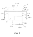
- the cardboard box C used by the box making / box packing system 1, as shown in FIG. 2 and FIG. 5 has an annularly formed side face portion C1 having four side faces C11-C14, and a total of eight tabular flaps C2 each extending forward or rearward from the four side faces C11-C14.
- the flaps C2 of the bottom lid side is closed by the box making device 2 and the bottom lid B is formed.
- the flaps C21-C24 (C2) of the upper lid side (front side) are opened outwardly. As shown in FIG.
- the front faces C21a-C24a of the flaps C21-C24 are arranged at the front side, while the rear faces C21b-C24b of the flaps C21-C24 are arranged at the rear side.
- the cardboard box C is supplied to the box packing device 10 in the state in which the side face C14 is directed downward, as shown in FIG. 2 .
- the box packing device 10 is mainly provided with a dropping part 20, a pushing part 40, a position and orientation changing part 50, an article transporting part 60, and a control device 70.
- the dropping part 20 changes the height position of the cardboard box C by dropping the cardboard box C, being supplied from the box making device 2 via the conveyor, in a state in which the side face C14 is directed downward and the opening is directed forward.
- the pushing part 40 pushes an article A (the article to be packed) conveyed by the article transporting part 60, from the side (from the front side), into the cardboard box C dropped by the dropping part 20.
- the position and orientation changing part 50 adjusts the height position of the cardboard box C.
- the position and orientation changing part 50 raises the cardboard box C which is open forward and contains the article A, such that the opening of the cardboard box C faces upward.
- the control device 70 controls the movements of the dropping part 20, the pushing part 40, the position and orientation changing part 50, and the article transporting part 60 and the like.
- the dropping part 20, the pushing part 40, the position and orientation changing part 50, the article transporting part 60 and the control device 70 are described in detail subsequently.
- the cardboard box C raised by the position and orientation changing part 50 such that the opening faces upward is then conveyed by a conveyor not shown in the drawing and supplied to the box closing device 3.
- the box closing device 3 closes the flaps C2 of the upper lid side (flaps C21-C24) and thereby forms the upper lid.
- the cardboard box C whose upper lid is closed by the box closing device 3 is conveyed from the box making / box packing system 1 by a conveyor not shown in the drawing.
- the dropping part 20 changes the height position of the cardboard box C by dropping the forward opened cardboard box C, being supplied from the box making device 2 via a conveyor, with the side face C14 directed downward.
- the flap C22 extending from the upper side face C12
- the flaps C21, C23 extending from the lateral side faces C11, C13
- the flap C24 extending from the lower side face C14 are open outward.
- the height position of the cardboard box C is changed by the dropping part 20, in the state where the opening of the cardboard box C is not covered by the flaps C21-C24.
- the dropping part 20 has an upper guide mechanism 21 and a lower guide mechanism 30.
- the upper guide mechanism 21 restricts movement of the flaps C21, C23 arranged at the lateral sides of the cardboard box C such that those flaps do not close when the cardboard box C drops. As movement of the flaps C21, C23 is restricted by the upper guide mechanism 21, the cardboard box C drops in the predetermined posture and in the predetermined position.
- the upper guide mechanism 21 includes first upper guide portions 22 and 23 arranged opposing the front faces C21 a and C23a of the flaps C21 and C23 of the dropping cardboard box C and the second upper guide portions 24, 25 arranged opposing the rear faces C21 b, C23b of the flaps C21, C23 of the dropping cardboard box C.
- the first upper guide portion 22 and the second upper guide portion 24 are arranged so as to be mutually opposed and are formed in a single integrated U-shaped body as the right guide portion G1 restricting movement of the flap C21.
- the first upper guide portion 23 and the second upper guide portion 25 are arranged so as to be mutually opposed and are formed in a single integrated U-shaped body as the left guide portion G2 restricting movement of the flap C23.
- the right guide portion G1 and the left guide portion G2 are substantially bilateral symmetrically configured in a top view.
- the flap C21 passes through the right guide portion G1 of substantially U-shaped form, and the flap C23 passes through the left guide portion G2 of substantially U-shaped form.
- the front face C21 a and the rear face C21b of the flap C21 of the cardboard box C in the process of dropping oppose the guide plane 22a of the first upper guide portion 22 and the guide plane 24a of the second upper guide portion 24.
- the front face C23a and the rear face C23b of the flap C23 of the cardboard box C in the process of dropping oppose the guide plane 23a of the first upper guide portion 23 and the guide plane 25a of the second upper guide portion 25.
- the guide plane 22a of the first upper guide portion 22 and the guide plane 24a of the second upper guide portion 24 are parallel.
- the guide plane 23a of the first upper guide portion 23 and the guide plane 25a of the second upper guide portion 25 are parallel.
- parallel includes being substantially parallel.
- the minimum distance between the first upper guide portion 22 and the second upper guide portion 24, that is, the distance L1 between the guide plane 22a of the first upper guide portion 22 and the guide plane 24a of the second upper guide portion 24 is determined such that the cardboard box C in the process of dropping does not get caught between the first upper guide portion 22 and the second upper guide portion 24. Further, the distance L1 is determined such that horizontal movement of the flap C21 can be restricted to some degree, in order to drop the cardboard box C in the predetermined posture and in the predetermined position. In determining the distance L1, not only unused cardboard boxes C but also used cardboard boxes C (reused boxes) are envisaged to be used by the box packing device 10.
- the distance between the guide plane 23a of the first upper guide portion 23 and the guide plane 25a of the second upper guide portion 25 is substantially the same as the distance L1 between the guide plane 22a of the first upper guide portion 22 and the guide plane 24a of the second upper guide portion 24.
- the lower guide mechanism 30 functions in the same manner as the upper guide mechanism 21 while the cardboard box C is dropping. That is, the lower guide mechanism 30 restricts movement of the flaps C21, C23 arranged at the lateral sides of the cardboard box C such that these flaps do not close. As movement of the flaps C21, C23 of the cardboard box C in the process of dropping is restricted by the lower guide mechanism 30, the cardboard box C drops in the predetermined posture and in the predetermined position.
- the lower guide mechanism 30 restricts movement of the flaps C21, C23 arranged at the lateral sides of the cardboard box C more strongly than while the cardboard box C is dropping. As movement of the flaps C21, C23 of the cardboard box C that has dropped is tightly restricted by the lower guide mechanism 30, movement of the cardboard box C in the horizontal direction (falling rearward) is restricted when article A is pushed into the cardboard box C.
- the lower guide mechanism 30 has a first lower guide including a first lower movable guide portion 31 and a first lower fixed guide portion 32 (refer FIG. 5 ), second lower guide portions 33, 34 (refer FIG. 5 ), and a first drive unit 37 (refer FIG. 3 ) for driving the second lower guide portions 33, 34. Further, the lower guide mechanism 30 has a second drive unit 38 (refer FIG. 3 ) for driving the first lower movable guide portion 31, and a third drive unit 39 (refer FIG. 3 ) for driving movable hooks 35, 36 provided to the second lower guide portions 33, 34 described subsequently.
- the first lower movable guide portion 31 is a plate shaped member arranged opposing the front face C21 a of the flap C21 of the cardboard box C when the cardboard box C drops and after the cardboard box C drops.
- the first lower movable guide portion 31 has a guide plane 31 a that opposes the front face C21 a of the flap C21.
- the first lower movable guide portion 31 functions as a pair with the second lower guide portion 33 to restrict movement of the flap C21.
- the guide plane 31 a of the first lower movable guide portion 31 opposes the front face C22a of the flap C22 arranged to the upper side of the cardboard box C when the cardboard box C drops and after the cardboard box C drops. That is, the first lower movable guide portion 31 restricts movement of the flap C22 in addition to movement of the flap C21 for preventing the flap C22 from closing (falling forward).
- the first lower movable guide portion 31 is driven by the second drive unit 38 in the forward-rearward and the leftward-rightward directions. The movement of the first lower movable guide portion 31 is described subsequently.
- the first lower fixed guide portion 32 is a plate shaped member arranged opposing the front face C23a of the flap C23 of the cardboard box C when the cardboard box C drops and after the cardboard box C drops.
- the first lower fixed guide portion 32 has a guide plane 32a that opposes the front face C23a of the flap C23.
- the first lower fixed guide portion 32 functions as a pair with the second lower guide portion 34 to restrict movement of the flap C23.
- the first lower fixed guide portion 32 is fixed in position, unlike the first lower movable guide portion 31.
- the second lower guide portion 33 is a member having a substantially L-shaped form in top view. As shown in FIG. 6 , the second lower guide portion 33 has a guide plane 33a extending in the leftward-rightward direction in FIG. 5 and a lateral guide plane 33b extending rearward from the left end of the guide plane 33a.
- the guide plane 33a opposes the rear face C21 b of the flap C21 of the cardboard box C when the cardboard box C drops and after the cardboard box C drops.
- the lateral guide plane 33b opposes the side face portion C1 (side face C11) of the cardboard box C when the cardboard box C drops and after the cardboard box C drops. Further, as shown in FIG.
- a movable hook 35 is provided to the lower part of the second lower guide portion 33, which is configured to be rotatable around the rotation axis 35b extending in the forward-rearward direction in FIG. 5 .
- the movable hook 35 has a side face 35c that opposes the side face portion C1 (side face C11) of the cardboard box C when the cardboard box C drops and a protruding portion 35d that protrudes from the lower end of the side face 35c to the left in FIG. 5 .
- the protruding portion 35d catches the side face C14 of the cardboard box C when the cardboard box C drops.
- the second lower guide portion 34 is a member having a substantially L-shaped form in top view. As shown in FIG. 7 , the second lower guide portion 34 has a guide plane 34a extending in the leftward-rightward direction in FIG. 5 and a lateral guide plane 34b extending rearward from the right end of the guide plane 34a.
- the guide plane 34a opposes the rear face C23b of the flap C23 of the cardboard box C when the cardboard box C drops and after the cardboard box C drops.
- the lateral guide plane 34b opposes the side face portion C1 (side face C13) of the cardboard box C when the cardboard box C drops and after the cardboard box C drops. Further, as shown in FIG.
- a movable hook 36 is provided to the lower part of the second lower guide portion 34, which is configured to be rotatable around the rotation axis 36b extending in the forward-rearward direction in FIG. 5 .
- the movable hook 36 has a side face 36c that opposes the side face portion C1 (side face C13) of the cardboard box C when the cardboard box C drops and a protruding portion 36d that protrudes from the lower end of the side face 36c to the right in FIG. 5 .
- the protruding portion 36d catches the side face C14 of the cardboard box C when the cardboard box C drops.
- the second lower guide portions 33, 34 are driven in the forward-rearward direction by the first drive unit 37.
- the movable hooks 35, 36 are driven by the third drive unit 39, so as to turn either clockwise or anticlockwise viewed from the rear side. The movements of the second lower guide portions 33, 34 and the movable hooks 35, 36 are described subsequently.
- the first drive unit 37 is an air cylinder that drives the second lower guide portions 33, 34 in the forward-rearward direction.
- the first drive unit 37 drives (moves) the second lower guide portion 33 forward so that it approaches the first lower movable guide portion 31 and drives (moves) the second lower guide portion 34 forward so that it approaches the first lower fixed guide portion 32 after the cardboard box C has dropped.
- the first drive unit 37 drives the second lower guide portion 33 and the second lower guide portion 34 forward, the second lower guide portion 33 is brought into contact with the flap C21 and the second lower guide portion 34 is brought into contact with the flap C23 to move the cardboard box C forward in horizontal direction. That is, the first drive unit 37 performs the function of moving the cardboard box C horizontally.
- the second drive unit 38 is an air cylinder that drives the first lower movable guide portion 31 in the forward-rearward direction and the leftward-rightward direction. That is, the second drive unit 38 is an air cylinder that drives the first lower movable guide portion 31 in the forward-rearward direction and in the direction parallel to the front face C22a of the flap C22 that is in the state of extending perpendicularly from the side face portion C1.
- parallel direction includes being substantially parallel direction.
- the third drive unit 39 is an air cylinder that rotationally drives the movable hooks 35, 36 so as to turn either clockwise or anticlockwise viewed from the rear side.
- the first drive unit 37, the second drive unit 38 and the third drive unit 39 are controlled by the control device 70 described subsequently.
- the operation and the timing of the operation of the second lower guide portions 33, 34, the first lower movable guide portion 31 and the movable hooks 35, 36 with the first drive unit 37, the second drive unit 38 and the third drive unit 39 are described subsequently.
- the pushing part 40 pushes the article A that has been conveyed by the article transporting part 60 into the cardboard box C which has been moved into the predetermined position for packing articles by the first drive unit 37 and the position and orientation changing part 50 as described subsequently.
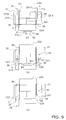
- the pushing part 40 has a pushing member 41 (refer FIG. 8 ) arranged so as to oppose the opening of the cardboard box C and a pushing drive unit 42 (refer FIG. 3 ), to move the pushing member 41 in the forward-rearward direction.
- the pushing drive unit 42 is controlled by the control device 70 described subsequently.
- the timing of the operation of the pushing member 41 with the pushing drive unit 42 is described subsequently.
- the position and orientation changing part 50 adjusts (changes) the height position of the cardboard box C when the article A is pushed by the pushing part 40. Further the position and orientation changing part 50 raises the cardboard box C which faces its opening forward and into which the article A has been placed, such that the opening faces upward.
- the position and orientation changing part 50 has a suction holding plate 51, suction cups 52 (refer FIG. 9 ), a suction driving unit 53, a vertical driving unit 54, and a rotary driving unit 55 (refer FIG. 3 ).
- the suction holding plate 51 is a plate shaped member, having a holding surface 51 a that contacts the side face C14 arranged to the lower side of the cardboard box C when the article A is pushed into the cardboard box C. As shown in FIG. 9(a) , the holding surface 51 a is provided with a plurality of suction cups 52 that stick to the side face C14. The suction operation of the suction cups 52 is driven by the suction driving unit 53.
- the vertical driving unit 54 and the rotary driving unit 55 change the position and orientation of the suction holding plate 51 while the suction cups 52 stick to the side face C14 of the cardboard box C, and thereby change the position and orientation of the cardboard box C.
- the rotary driving unit 55 rotates the suction holding plate 51 around a rotational axis extending horizontally in the leftward-rightward direction and changes the orientation of the suction holding plate 51 such that the holding surface 51 a facing rearward come to face upward or the holding surface 51 a facing upward come to face rearward.
- the vertical driving unit 54 vertically moves the suction holding plate 51 in the state where the holding surface 51 a faces upward.
- the suction driving unit 53, the vertical driving unit 54 and the rotary driving unit 55 are controlled by the control device 70 described subsequently.
- the timing in which the suction cups 52, driven by the suction driving unit 53, sticks to the side face C14 of the cardboard box C, and the operation and timing of the operation of the suction holding plate 51 with the vertical driving unit 54 and the rotary driving unit 55, are described subsequently.
- the article transporting part 60 conveys the article A to be packed into the cardboard box C (refer FIG. 8 ).
- the article transporting part 60 is driven by a transport driving unit 61 (refer FIG. 3 ), to convey the article A at the predetermined speed and timing.
- the transport driving unit 61 drives the article transporting part 60 so that the article A is conveyed to the rear side of the pushing member 41 of the pushing part 40 (between the pushing member 41 and the opening of the cardboard box C) when the cardboard box C is moved into the predetermined position for packing articles by the first drive unit 37 and the position and orientation changing part 50.
- the operation of the transport driving unit 61 is controlled by the control device 70 described subsequently.
- the control device 70 is connected to each of the dropping part 20, the pushing part 40, the position and orientation changing part 50 and the article transporting part 60.
- the control device 70 is also connected to the box making device 2 arranged at a prior stage and the box closing device 3 arranged at a subsequent stage in the box packing device 10.
- the control device 70 mainly controls various parts of the box packing device 10 and exchange various information with various parts of the box packing device 10
- the control device 70 includes a memory unit 71 and a control unit 72 as shown in FIG. 3 .
- the memory unit 71 is comprised primarily of ROM, RAM or a hard disk drive (HDD) or the like.
- the control unit 72 is comprises primarily of a CPU.
- control unit 72 Various programs to be executed by the control unit 72 are stored in the memory unit 71. Further, various operating parameters required for the control unit 72 to control the box packing device 10 are stored in the memory unit 71.
- the control unit 72 reads out and executes various programs stored in the memory unit 71, and controls various parts of the box packing device 10, including the dropping part 20, the pushing part 40, the position and orientation changing part 50, the article transporting part 60 and the like.
- control unit 72 controls the first through third drive units 37-39 of the dropping part 20, and thereby causes the second lower guide portions 33, 34, the first lower movable guide portion 31 and the movable hooks 35, 36 to perform the predetermined operation at the predetermined timing.
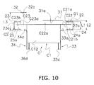
- FIG. 10 shows the arrangement of each member of the lower guide mechanism 30 when the cardboard box C drops, viewed from the above.
- the arrangement, regarding the forward-rearward direction in FIG. 5 , of the first lower movable guide portion 31, the first lower fixed guide portion 32 and the second lower guide portions 33, 34 will now be described using FIG. 10 .
- FIG. 10 the right guide portion G1 and the left guide portion G2 of the upper guide mechanism 21 are also shown by the two-dot chain line.
- the second lower guide portions 33, 34 are substantially bilateral symmetrically arranged in the top view. That is, the second lower guide portions 33, 34 are arranged such that the guide plane 33a of the second lower guide portion 33 and the guide plane 34a of the second lower guide portion 34 are disposed substantially on the same plane.
- the guide planes 33a, 34a of the second lower guide portions 33, 34 are disposed further rearward in FIG. 5 than the guide planes 24a, 25a of the second upper guide portions 24, 25.
- the first lower movable guide portion 31 is arranged to the front side in FIG. 5 of the second lower guide portion 33 such that the minimum distance between the first lower movable guide portion 31 and the second lower guide portion 33, that is, the distance between the guide plane 31 a of the first lower movable guide portion 31 and the guide plane 33a of the second lower guide portion 33, becomes L2.
- the guide plane 31 a of the first lower movable guide portion 31 is disposed further forward in FIG. 5 than the guide plane 22a of the first upper guide portion 22.
- the first lower fixed guide portion 32 is arranged to the front side in FIG. 5 of the second lower guide portion 34, such that the minimum distance between the first lower fixed guide portion 32 and the second lower guide portion 34, that is, the distance between the guide plane 32a of the first lower fixed guide portion 32 and the guide plane 34a of the second lower guide portion 34, is L3.
- the guide plane 32a of the first lower fixed guide portion 32 is arranged further forward in FIG. 5 than the guide plane 23a of the first upper guide portion 23.
- the distances L2 and L3 are greater values than the distance L1 between the guide plane 22a of the first upper guide portion 22 and the guide plane 24a of the second upper guide portion 24 in the upper guide mechanism 21. Further, the distance L3 is a greater value than the distance L2. Because the distance L2 and the distance L3 are equal to or greater than the distance L1, the cardboard box C are hardly caught by the lower guide mechanism 30 when dropping.
- the passage through which the flaps C21, C23 pass in the upper guide mechanism 21 (the passage formed between the first upper guide portion 22 and the second upper guide portion 24 and the passage formed between the first upper guide portion 23 and the second upper guide portion 25) is included within the passage through which the flaps C21, C23 pass in the lower guide mechanism 30 (the passage formed between the first lower movable guide portion 31 and the second lower guide portion 33 and the passage formed between the first lower fixed guide portion 32 and the lower guide portion 34).
- the flap C21 and the flap C23 having passed through the upper guide mechanism 21 do not run away from the lower guide mechanism 30.
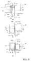
- FIG. 9(a) depicts the vicinity of the lower guide mechanism 30 immediately after the cardboard box C drops.
- the arrangement of the first lower movable guide portion 31, the first lower fixed guide portion 32, and the second lower guide portions 33, 34 is the same as the arrangement of these while the cardboard box C is dropping.
- the arrangement, regarding the leftward-rightward direction in FIG. 5 , of the first lower movable guide portion 31, the first lower fixed guide portion 32, and the second lower guide portions 33, 34 will now be described using FIG. 9(a) and FIG. 10 .
- the second lower guide portions 33, 34 are substantially bilateral symmetrically arranged in relation to the center of the cardboard box C in the leftward-rightward direction.
- the second lower guide portion 33 opposes the rear face C21 b of the flap C21 in the vicinity of a boundary between the flap C21 and the side face portion C1.
- the second lower guide portion 34 opposes the rear face C23b of the flap C23 in the vicinity of a boundary between the flap C23 and the side face portion C1.
- the second lower guide portions 33, 34 are not driven in the leftward-rightward direction, while the article A is being pushed into the cardboard box C, the second lower guide portion 33 opposes the rear face C21b of the flap C21 in the vicinity of the boundary between the flap C21 and the side face portion C1, and the second lower guide portion 34 opposes the rear face C23b of the flap C23 in the vicinity of the boundary between the flap C23 and the side face portion C1.
- the first lower movable guide portion 31 opposes the center part, in the leftward-rightward direction, of the front face C22a of the flap C22 arranged at the upper side.
- the center part in the leftward-rightward direction here, means the area around the center and does not necessarily include the center in the leftward-rightward direction.
- the first lower movable guide portion 31 extends to the right and opposes the left end part (the vicinity of the boundary between the flap C21 and the side face portion C1) of the front face C22a of the flap C21.
- the first lower fixed guide portion 32 opposes the front face C23a of the flap C23 in the vicinity of the boundary between the flap C23 and the side face portion C1. Because the first lower fixed guide portion 32 does not move, while the article A is being pushed into the cardboard box C, the first lower fixed guide portion 32 opposes the front face C23a of the flap C23 in the vicinity of the boundary between the flap C23 and the side face portion C1.
- the first lower movable guide portion 31, the first lower fixed guide portion 32, and the second lower guide portions 33, 34 are arranged at a height where they oppose the flaps C21 or C23 immediately after the cardboard box C drops (refer FIG. 8(a) , FIG. 9(a) ).
- step S1 the cardboard box C drops in the dropping part 20. Specifically, the cardboard box C passes through the upper guide mechanism 21 portion such that the flap C21 passes through the inside of the right guide portion G1 of the upper guide mechanism 21 and the flap C23 passes through the inside of the left guide portion G2 of the upper guide mechanism 21. Further, the cardboard box C drops in the lower guide mechanism 30, such that the flap C21 passes between the first lower movable guide portion 31 and the second lower guide portion 33 and the flap C23 passes between the first lower fixed guide portion 32 and the second lower guide portion 34. The cardboard box C drops onto the protruding portions 35d, 36d of the movable hooks 35, 36 and is caught by the protruding portions 35d, 36d. At this point, the cardboard box C has finished dropping.
- step S2 instructed by the control device 70, the second drive unit 38 drives the first lower movable guide portion 31 rightward as indicated by arrow D6 in FIG. 9(a) .
- the second drive unit 38 drives the first lower movable guide portion 31 into a position opposing only the right end part of the front face C22a of the flap C22 as shown in FIG. 9(b) .
- the first lower movable guide portion 31 opposes the front face C21 a of the flap C21 in the vicinity of the boundary between the flap C21 and the side face portion C1.
- the opening of the cardboard box C is scarcely covered by the first lower movable guide portion 31 and is kept wide open. Further, as a part of the first lower movable guide portion 31 opposes the front face C22a of the flap C22, the flap C22 is prevented from falling forward.
- the second drive unit 38 drives the first lower movable guide portion 31 forward as indicated by the arrow D1 in FIG. 8(a) . More specifically, the second drive unit 38 drives the first lower movable guide portion 31 forward to a position where the guide plane 31 a of the first lower movable guide portion 31 and the guide plane 32a of the first lower fixed guide portion 32 are substantially aligned when viewed from the side (refer FIG. 8(b) ).
- the guide plane 31 a and the guide plane 32a are arranged on substantially the same plane.
- step S2 instructed by the control device 70, the first drive unit 37 drives the second lower guide portion 33 forward, as indicated by the arrow D2 in FIG. 8(a) . Further, the first drive unit 37 also drives the second lower guide portion 34 forward at the same timing and speed. At this time, the guide plane 33a of the second lower guide portion 33 comes into contact with the rear face C21 b of the flap C21 and the guide plane 34a of the second lower guide portion 34 comes into contact with the rear face C23b of the flap C23, and thereby the cardboard box C is moved forward.
- the first drive unit 37 drives the second lower guide portion 33 forward such that the distance between the guide plane 33a of the second lower guide portion 33 and the guide plane 31 a of the first lower movable guide portion 31 becomes L4. Further, the first drive unit 37 drives the second lower guide portion 34 forward such that the distance between the guide plane 34a of the second lower guide portion 34 and the guide plane 32a of the first lower fixed guide portion 32 becomes L4.
- a value as close as possible to the thickness of the flap C21 (and the flap C23) is determined as the distance L4, within the scope that the flap C21 is not stuck between the first lower movable guide portion 31 and the second lower guide portion 33 (and the flap C23 is not stuck between the first lower fixed guide portion 32 and the lower guide portion 34) when the cardboard box C is moved vertically in step S4 and step S6 described subsequently.
- step S2 instructed by the control device 70, the rotary driving unit 55 rotates the suction holding plate 51 around the rotational axis extending in the leftward-rightward direction as indicated by the arrow D3 in FIG. 8(a) and changes the orientation of the suction holding plate 51 such that the holding surface 51 a facing to the rear side as shown in FIG. 9(a) comes to oppose the side face C14 arranged at the bottom of the cardboard box C as shown in FIG. 9(b) .
- step S3 instructed by the control device 70, the vertical driving unit 54 drives the suction holding plate 51 in the direction of the arrow D4 in FIG. 8(b) (upward), such that the holding surface 51 a of the suction holding plate 51 contacts the side face C14 of the cardboard box C. Further, instructed by the control device 70, the suction cups 52 driven by the suction driving unit 53 sticks to the side face C14 arranged at the bottom of the cardboard box C such that the cardboard box C and the suction cups 52 are connected.
- step S3 instructed by the control device 70, the third drive unit 39 rotationally drives the movable hooks 35, 36 into positions away from the cardboard box C.
- the third drive unit 39 rotates the movable hook 35 counterclockwise as indicated by arrow D7 in FIG. 9(b) and rotates the movable hook 36 clockwise as indicated by arrow D8 in FIG. 9(b) .
- the movable hooks 35, 36 enter a state of not being in contact with the cardboard box C as in FIG. 9(c) .
- step S4 instructed by the control device 70, the vertical driving unit 54 vertically drives the suction holding plate 51 to move the cardboard box C vertically into the position where the article A is pushed into the cardboard box C.
- the flap C21 moves in the gap, having the distance L4, between the guide plane 31 a of the first lower movable guide portion 31 and the guide plane 33a of the second lower guide portion 33.
- the flap C22 moves in the gap, having the distance L4, between the guide plane 32a of the first lower fixed guide portion 32 and the guide plane 34a of the second lower guide portion 34.
- the position where an article is pushed into the cardboard box C is the position substantially adjacent to the article transporting part 60, at which the height of the conveyance surface where the article A is conveyed by the pushing member 41 and the height of the inner face of the side face C14 of the cardboard box C are substantially the same.
- step S5 instructed by the control device 70, the pushing drive unit 42 drives the pushing member 41 rearward in FIG. 5 , as indicated by the arrow D5 in FIG. 8(c) , such that the predetermined quantity of articles A conveyed by the article transporting part 60 are pushed into the cardboard box C. A single article A or a plurality of articles A are pushed into the cardboard box C.
- step S6 instructed by the control device 70, the vertical driving unit 54 vertically drives the suction holding plate 51 mounted with the cardboard box C on the holding surface 51 a. Specifically, the vertical driving unit 54 vertically moves the suction holding plate 51 into a position at which the orientation of the suction holding plate 51 can be changed by the rotary driving unit 55.
- step S7 instructed by the control device 70, the first drive unit 37 and the second drive unit 38 start operation to drive the second lower guide portions 33, 34 and the first lower movable guide portion 31 in the opposite direction to that in step S2. That is, the first drive unit 37 and the second drive unit 38 return the first lower movable guide portion 31 and the second lower guide portions 33, 34 to their respective positions when the cardboard box C is in the process of dropping (the positions at the time of step S1).
- step S7 instructed by the control device 70, the rotary driving unit 55 starts operation to rotationally drive the suction holding plate 51 in the opposite direction to that of step S2. That is, the rotary driving unit 55 rotates the orientation of the suction holding plate 51 anticlockwise in the right side view in the state where the side face C14 of the cardboard box C is secured by the suction cups 52 such that the upward directed holding surface 51 a faces toward the rear side. Resultantly, the cardboard box C is placed onto the surface of a conveyor, not shown in the drawing, in the state in which the opening of the cardboard box C faces upward. Note that in this state, the position of the suction holding plate 51 returns to the position when the cardboard box C is in the process of dropping (the position at the time of step S1).
- step S8 instructed by the control device 70, drive of the suction driving unit 53 is stopped, and the suction cups 52 release the side face C14 of the cardboard box C.
- the cardboard box C being not secured by the suction cups 52 is conveyed by a conveyor not shown in the drawing toward the box closing device 3.
- the box packing device 10 is provided with the dropping part 20 for dropping the cardboard box C used for packing to change the height position of the cardboard box C.
- the cardboard box C has the annular formed side face portion C1 having the four side faces C11-C14 and the four flaps C21-C24, as tabular lid portions, extending respectively from the four side faces C11-C14.
- the dropping part 20 positions the side face C14 of the four side faces C11-C14 to the bottom and drops the cardboard box C in the state that the flap C22, as the upper lid portion, extending from the upper side face C12 among the four flaps C21-C24 and the flaps C21 and C23, as the first and second lateral lid portions, extending from the lateral side faces C11 and C13 among the four flaps C21-C24 are opened outward.
- the dropping part 20 has the upper guide mechanism 21 and the lower guide mechanism 30 arranged below the upper guide mechanism 21.
- the upper guide mechanism 21 includes the first upper guide portions 22, 23, as the first guide portion, arranged so as to oppose the front faces C21 a, C23a of the flaps C21 and C23 when the cardboard box C drops and the second upper guide portions 24, 25, as the second guide portion, arranged so as to oppose the rear faces C21 b, C23b of the flaps C21, C23 when the cardboard box C drops.
- the lower guide mechanism 30 includes the first lower movable guide portion 31 and the first lower fixed guide portion 32, as the third guide portion, arranged so as to oppose the front faces C21 a, C23a of the flaps C21, C23 when the cardboard box C drops and after the cardboard box C drops, the second lower guide portions 33, 34, as the fourth guide portion, arranged so as to oppose the rear faces C21 b , C23b of the flaps C21, C23 when the cardboard box C drops and after the cardboard box C drops, and the first drive unit 37 for driving the second lower guide portions 33, 34 toward the first lower movable guide portion 31 and the first lower fixed guide portion 32 after the cardboard box C drops.
- the passage through which the flaps C21, C23 pass can be kept wide open until the cardboard box C drops, and after the cardboard box C drops, movement of the flaps C21, C23 can be highly restricted such that the cardboard box C is kept in the appropriate posture and position. Resultantly, a highly reliable box packing device 10 can be provided.
- the first lower movable guide portion 31 and the first lower fixed guide portion 32, and the second lower guide portions 33, 34 are arranged such that, when the cardboard box C drops, the minimum distance between the first lower movable guide portion 31 and the second lower guide portion 33 and the minimum distance between the first lower fixed guide portion 32 and the second lower guide portion 34 are equal to or greater than the minimum distance between the first upper guide portion 22 and the second upper guide portion 24 (the minimum distance between the first upper guide portion 23 and the second upper guide portion 24).
- the first lower movable guide portion 31 and the first lower fixed guide portion 32, and the second lower guide portions 33, 34 are arranged such that, when the cardboard box C drops, the distance L2 between the guide plane 31 a of the first lower movable guide portion 31 and the guide plane 33a of the second lower guide portion 33 and the distance L3 between the guide plane 32a of the first lower fixed guide portion 32 and the guide plane 34a of the second lower guide portion 34 are equal to or greater than the distance L1 1 between the guide plane 22a of the first upper guide portion 22 and the guide plane 24a of the second upper guide portion 24 (the distance L1 between the guide plane 23a of the first upper guide portion 23 and the guide plane 25a of the second upper guide portion 25).
- the first lower movable guide portion 31, as the third guide portion is arranged further forward than the first upper guide portion 22, and the first lower fixed guide portion 32, as the third guide portion, is arranged further forward than the first upper guide portion 23.
- the second lower guide portion 33, as the fourth guide portion is arranged further rearward than the second upper guide portion 24, and the second lower guide portion 34, as the fourth guide portion, is arranged further rearward than the second upper guide portion 25.
- the passage through which the flaps C21, C23 pass in the upper guide mechanism 21 (the passage formed between the first upper guide portion 22 and the second upper guide portion 24 and the passage formed between the first upper guide portion 23 and the second upper guide portion 25) is included within the passage through which the flaps C21, C23 pass in the lower guide mechanism 30 (the passage formed between the first lower movable guide portion 31 and the second lower guide portion 33 and the passage formed between the first lower fixed guide portion 32 and the lower guide portion 34).
- the upper guide mechanism 21 includes the first upper guide portions 22, 23 having the guide planes 22a, 23a that oppose the front faces C21 a, C23a of the flaps C21, C23 when the cardboard box C drops and the second upper guide portions 24, 25 having the guide planes 24a, 25a that oppose the rear faces C21 b, C23b of the flaps C21, C23 when the cardboard box C drops.
- the lower guide mechanism 30 includes the first lower movable guide portion 31 and the first lower fixed guide portion 32 having the guide planes 31 a, 32a that oppose the front faces C21 a, C23a of the flaps C21, C23 when the cardboard box C drops and after the cardboard box C drops and the second lower guide portions 33, 34 having the guide planes 33a, 34a that oppose the rear faces C21 b , C23b of the flaps C21, C23 when the cardboard box C drops and after the cardboard box C drops.
- the front faces C21 a, C23a and the rear faces C21 b, C23b of the flaps C21, C23 are guided by the planes in the upper guide mechanism 21 and the lower guide mechanism 30, movement of the flaps C21, C23 can be highly restricted. Resultantly, the cardboard box C can be held in the appropriate posture and position, and the highly reliable box packing device 10 can be provided.
- the first lower movable guide portion 31 and the first lower fixed guide portion 32 oppose the front faces C21 a, C23a of the flaps C21, C23 in the vicinity of the boundary between the flaps C21, C23 and the side face portion C1.
- the second lower guide portions 33, 34 oppose the rear faces C21b, C23b of the flaps C21, C23 in the vicinity of the boundary between the flaps C21, C23 and the side face portion C1.
- first lower movable guide portion 31 and the first lower fixed guide portion 32, and the second lower guide portions 33, 34 restrict movement of the flaps C21, C23 in the vicinity of the boundary of the side face portion C1 and the flaps C21, C23 (in the area at the base of the flaps C21, C23), movement of the cardboard box C can be more stringently restricted in comparison to the case that movement of the flaps C21, C23 is restricted at the end parts of the flaps C21, C23.
- the first lower movable guide portion 31, as the third guide portion opposes the front face C22a of the flap C22 as the upper lid portion.
- the box packing device 10 has the first lower fixed guide portion 32 that opposes the front face C23a of the flap C23 and the first lower movable guide portion 31 that opposes the front face C21 a of the flap C21 and the front face C22a of the flap C22 as the third guide portion.
- the first lower movable guide portion 31 opposes the center part of the front face C22a of the flap C22 when the cardboard box C drops.
- the lower guide mechanism 30 includes the second drive unit 38 for driving the first lower movable guide portion 31 substantially in parallel to the front face C22a of the flap C22 after the cardboard box C drops.
- the second drive unit 38 drives the first lower movable guide portion 31 to the position where the first lower movable guide portion 31 opposes the front face C22a of the flap C22 only at the end part of the flap C22 after the cardboard box C drops.
- the first lower movable guide portion 31 is arranged forward of the flap C21, and opposes the center part of the front face C22a of the flap C22 when the cardboard box C drops, and opposes only the end part of the front face C22a of the flap C22 after the cardboard box C drops. Accordingly, the first lower movable guide portion 31 can easily be prevent that the flap C22 falls forward when the cardboard box C drops. On the other hand, after the cardboard box C drops, the opening of the cardboard box C can be kept open wide while the first lower movable guide portion 31 prevents the flap C22 from falling forward.
- the first drive unit 37 drives the second lower guide portions 33, 34 so that the second lower guide portions 33, 34 come into contact with the flaps C21, C23 and thereby to move the cardboard box C horizontally.
- the cardboard box C can be moved horizontally to the desired position by the first drive unit 37.
- the first drive unit 37 drives the second lower guide portions 33, 34, being the fourth guide portion, so as to approach the first lower movable guide portion 31 and the first lower fixed guide portion 32, being the third guide portions, but this is illustrative and not restrictive.
- the third guide portion may be driven toward the fourth guide portion to narrow the width of the gap between the third guide portion and the fourth guide portion in which the flaps C21 and C23 can move.
- the third guide portions and the fourth guide portions may be mutually driven toward each other.
- both the first upper guide portions 22, 23 as the first guide portion and the second upper guide portions 24, 25 as the second guide portions have guide planes (22a, 23a, 24a, 25a), but this is illustrative and not restrictive.
- the first upper guide portions 22, 23 may have the guide planes 22a, 23a, and the second upper guide portions 24, 25 may be rod shaped members.
- the second upper guide portions 24, 25 may have the guide planes 24a, 25a, and the first upper guide portions 22, 23 may be rod shaped members.
- both faces of the flaps C21, C23 front faces C21 a, C23a and rear faces C21 b, C23b) of the cardboard box C oppose guide planes.
- the first lower movable guide portion 31 of the flap C21 side being the third guide portion, is driven, but this is illustrative and not restrictive.
- the third guide portion on the flap C23 side may be driven.
- the article A is pushed into each cardboard box C by the pushing member 41 only once, but this is illustrative and not restrictive.
- the article A may be pushed into the cardboard box C in multiple stages as the height position of the cardboard box C is being changed by the position and orientation changing part 50.
- the box packing device according to the present invention moves downward a horizontally opened cardboard box by dropping it and is useful as a highly reliable box packing device which can drop the cardboard box without obstacle while maintaining the cardboard box in the appropriate posture after the box has dropped.
- Patent document 1
Landscapes
- Engineering & Computer Science (AREA)
- Mechanical Engineering (AREA)
- Container Filling Or Packaging Operations (AREA)
- Supplying Of Containers To The Packaging Station (AREA)
Applications Claiming Priority (2)
| Application Number | Priority Date | Filing Date | Title |
|---|---|---|---|
| JP2012207180A JP6052861B2 (ja) | 2012-09-20 | 2012-09-20 | 箱詰め装置 |
| PCT/JP2013/069749 WO2014045702A1 (fr) | 2012-09-20 | 2013-07-22 | Dispositif d'emballage de boîte |
Publications (3)
| Publication Number | Publication Date |
|---|---|
| EP2899129A1 true EP2899129A1 (fr) | 2015-07-29 |
| EP2899129A4 EP2899129A4 (fr) | 2016-04-20 |
| EP2899129B1 EP2899129B1 (fr) | 2016-11-16 |
Family
ID=50341028
Family Applications (1)
| Application Number | Title | Priority Date | Filing Date |
|---|---|---|---|
| EP13838887.1A Active EP2899129B1 (fr) | 2012-09-20 | 2013-07-22 | Dispositif d'emballage de boîte |
Country Status (4)
| Country | Link |
|---|---|
| US (2) | US9428293B2 (fr) |
| EP (1) | EP2899129B1 (fr) |
| JP (1) | JP6052861B2 (fr) |
| WO (1) | WO2014045702A1 (fr) |
Cited By (2)
| Publication number | Priority date | Publication date | Assignee | Title |
|---|---|---|---|---|
| NL2019235A (en) * | 2016-07-12 | 2018-01-15 | Ishida Seisakusho | Boxing apparatus |
| EP3912919A1 (fr) * | 2018-02-27 | 2021-11-24 | Ishida Co., Ltd. | Appareil de formation, d'emballage et de scellement de boîtier |
Families Citing this family (8)
| Publication number | Priority date | Publication date | Assignee | Title |
|---|---|---|---|---|
| JP6463147B2 (ja) | 2015-01-23 | 2019-01-30 | 株式会社イシダ | 箱詰め装置 |
| US10759550B2 (en) * | 2015-09-25 | 2020-09-01 | Douglas Machine Inc. | Intermittent case packer assembly and methods |
| JP6475646B2 (ja) * | 2016-01-25 | 2019-02-27 | 株式会社イシダ | 開函装置 |
| JP6996734B2 (ja) | 2017-08-18 | 2022-01-17 | 株式会社イシダ | 製函装置 |
| JP6967781B2 (ja) * | 2018-02-22 | 2021-11-17 | 株式会社イシダ | 箱詰め装置 |
| JP7199686B2 (ja) * | 2018-06-11 | 2023-01-06 | 株式会社イシダ | 箱詰め装置 |
| CA3021452A1 (fr) * | 2018-10-17 | 2020-04-17 | Thatbox Design, Llc | Procedes de fabrication ameliores et appareils pour recipients et emballages |
| CN114222703A (zh) * | 2019-09-27 | 2022-03-22 | 大王制纸株式会社 | 瓦楞纸制箱装置、制箱方法及制箱处理方法 |
Family Cites Families (24)
| Publication number | Priority date | Publication date | Assignee | Title |
|---|---|---|---|---|
| US3740919A (en) * | 1971-12-06 | 1973-06-26 | R Heisler | Apparatus and method for orienting and case packing bailed containers |
| US3848394A (en) * | 1973-06-26 | 1974-11-19 | R Heisler | Apparatus and method for orienting and case packing eared containers |
| US3941037A (en) * | 1974-10-07 | 1976-03-02 | A B C Packaging Machine Corporation | Case forming and transferring machine |
| US4018143A (en) * | 1975-05-02 | 1977-04-19 | Cal Crown Corporation | Cardboard box erecting machine |
| US4378080A (en) * | 1979-07-18 | 1983-03-29 | Nolex Corporation | Fluid velocity attenuating nozzle |
| US4633653A (en) | 1984-10-29 | 1987-01-06 | Roberts John T | Case packing apparatus |
| JP2844410B2 (ja) * | 1993-06-30 | 1999-01-06 | 花王株式会社 | コンテナへの物品収納方法及び装置 |
| JPH07241939A (ja) | 1994-03-07 | 1995-09-19 | Fuji Mach Co Ltd | 折畳みケースの開口方法および装置 |
| US5653671A (en) * | 1994-12-30 | 1997-08-05 | Riverwood International Corporation | Carton feeder assembly |
| US6066081A (en) * | 1995-11-03 | 2000-05-23 | Nimco Corporation | Method and apparatus for attaching a fitment to and sterilizing a container |
| US5732536A (en) | 1996-10-28 | 1998-03-31 | Industrial Technology Research Institute | Tape roll in-series package machine |
| JP2980120B1 (ja) * | 1998-09-11 | 1999-11-22 | 白柳式撰果機株式会社 | 果実等の傾倒式自動秤量機における二段切替箱詰装置 |
| JP2000185712A (ja) * | 1998-12-18 | 2000-07-04 | Okamoto Takeshi | 紙製引起し箱仮組立装置 |
| JP2000313412A (ja) * | 1999-04-30 | 2000-11-14 | Ishida Co Ltd | 箱詰めシステムにおける製品振り分け機構 |
| CN100425509C (zh) * | 2002-05-09 | 2008-10-15 | 富士胶片株式会社 | 包装对象供应设备、箱体供应设备、装箱设备、包装系统及包装方法 |
| JP2004155428A (ja) | 2002-11-01 | 2004-06-03 | Ishida Co Ltd | 箱詰装置 |
| JP2006069607A (ja) | 2004-09-01 | 2006-03-16 | Oji Chiyoda Container Kk | 段ボールシート供給方法および供給装置 |
| JP4572701B2 (ja) * | 2005-02-25 | 2010-11-04 | 凸版印刷株式会社 | 紙製液体包装容器製函充填機における容器搬送装置 |
| JP2007290751A (ja) * | 2006-04-26 | 2007-11-08 | Tamura Kikai Kogyo Kk | カートン逆折装置 |
| DE102008010432A1 (de) * | 2008-02-21 | 2009-08-27 | Focke & Co.(Gmbh & Co. Kg) | Verfahren und Vorrichtung zum Einführen von (Schlauch-)Beuteln in Kartons |
| JP2009249017A (ja) | 2008-04-09 | 2009-10-29 | Ishida Co Ltd | 製函装置およびこれを備えた箱詰装置 |
| JP5514524B2 (ja) * | 2009-11-30 | 2014-06-04 | 株式会社イシダ | 包装物の搬送装置 |
| JP5302039B2 (ja) * | 2009-02-16 | 2013-10-02 | 株式会社イシダ | 箱詰め装置 |
| WO2011119563A2 (fr) * | 2010-03-23 | 2011-09-29 | Douglas Machine Inc. | Appareil et procédé pour manipuler des caisses en carton |
-
2012
- 2012-09-20 JP JP2012207180A patent/JP6052861B2/ja active Active
-
2013
- 2013-07-22 WO PCT/JP2013/069749 patent/WO2014045702A1/fr active Application Filing
- 2013-07-22 US US14/429,528 patent/US9428293B2/en active Active
- 2013-07-22 EP EP13838887.1A patent/EP2899129B1/fr active Active
-
2015
- 2015-06-10 US US14/736,066 patent/US9908652B2/en active Active
Cited By (3)
| Publication number | Priority date | Publication date | Assignee | Title |
|---|---|---|---|---|
| NL2019235A (en) * | 2016-07-12 | 2018-01-15 | Ishida Seisakusho | Boxing apparatus |
| US10787281B2 (en) | 2016-07-12 | 2020-09-29 | Ishida Co., Ltd. | Boxing apparatus |
| EP3912919A1 (fr) * | 2018-02-27 | 2021-11-24 | Ishida Co., Ltd. | Appareil de formation, d'emballage et de scellement de boîtier |
Also Published As
| Publication number | Publication date |
|---|---|
| EP2899129A4 (fr) | 2016-04-20 |
| JP6052861B2 (ja) | 2016-12-27 |
| US9428293B2 (en) | 2016-08-30 |
| JP2014061903A (ja) | 2014-04-10 |
| US20150298842A1 (en) | 2015-10-22 |
| US20150232217A1 (en) | 2015-08-20 |
| EP2899129B1 (fr) | 2016-11-16 |
| WO2014045702A1 (fr) | 2014-03-27 |
| US9908652B2 (en) | 2018-03-06 |
Similar Documents
| Publication | Publication Date | Title |
|---|---|---|
| EP2899129A1 (fr) | Dispositif d'emballage de boîte | |
| JP6971718B2 (ja) | 荷物仕分け装置及び仕切り板 | |
| EP2716550B1 (fr) | Dispositif de remplissage de boîtes | |
| CN101515380B (zh) | 硬币处理机 | |
| EP3395694B1 (fr) | Appareil de remplissage de boîte | |
| CN104769648B (zh) | 介质处理装置 | |
| EP3248893B1 (fr) | Dispositif d'emballage de boîtes | |
| JP2014061904A (ja) | 箱詰め装置 | |
| EP3757023B1 (fr) | Dispositif d'emballage de boîte | |
| AU2017204754B2 (en) | Boxing apparatus | |
| CN103069558B (zh) | 晶片收纳装置和晶片盒收纳箱 | |
| WO2017135370A1 (fr) | Dispositif de traitement automatique, procédé de traitement automatique, et programme | |
| JP6857336B2 (ja) | 積み付けシステム、制御装置、積み付け方法、及び積み付けプログラム | |
| JP5388869B2 (ja) | 自動販売機 | |
| EP4067263A1 (fr) | Système de prélèvement | |
| JP7303465B2 (ja) | 貯蔵庫 | |
| JP4936995B2 (ja) | 棒金収納装置 | |
| JPS6245271Y2 (fr) | ||
| CN109835725A (zh) | 一种使用堆取料机进行湿料堆积的方法 | |
| JP2000268246A (ja) | 自動販売機の商品取り出し装置 | |
| JP2015095114A (ja) | 硬貨処理装置 | |
| CN114118889A (zh) | 储物架整理方法、装置、设备、介质及程序产品 | |
| JP2010257017A (ja) | 自動販売機の商品搬出装置 | |
| KR20140004841U (ko) | 가방 |
Legal Events
| Date | Code | Title | Description |
|---|---|---|---|
| PUAI | Public reference made under article 153(3) epc to a published international application that has entered the european phase |
Free format text: ORIGINAL CODE: 0009012 |
|
| 17P | Request for examination filed |
Effective date: 20150330 |
|
| AK | Designated contracting states |
Kind code of ref document: A1 Designated state(s): AL AT BE BG CH CY CZ DE DK EE ES FI FR GB GR HR HU IE IS IT LI LT LU LV MC MK MT NL NO PL PT RO RS SE SI SK SM TR |
|
| AX | Request for extension of the european patent |
Extension state: BA ME |
|
| DAX | Request for extension of the european patent (deleted) | ||
| RA4 | Supplementary search report drawn up and despatched (corrected) |
Effective date: 20160323 |
|
| RIC1 | Information provided on ipc code assigned before grant |
Ipc: B65B 43/54 20060101ALI20160316BHEP Ipc: B65B 43/12 20060101ALI20160316BHEP Ipc: B65B 43/26 20060101ALI20160316BHEP Ipc: B65B 5/00 20060101AFI20160316BHEP Ipc: B65B 43/42 20060101ALI20160316BHEP |
|
| GRAP | Despatch of communication of intention to grant a patent |
Free format text: ORIGINAL CODE: EPIDOSNIGR1 |
|
| INTG | Intention to grant announced |
Effective date: 20160722 |
|
| GRAS | Grant fee paid |
Free format text: ORIGINAL CODE: EPIDOSNIGR3 |
|
| GRAA | (expected) grant |
Free format text: ORIGINAL CODE: 0009210 |
|
| AK | Designated contracting states |
Kind code of ref document: B1 Designated state(s): AL AT BE BG CH CY CZ DE DK EE ES FI FR GB GR HR HU IE IS IT LI LT LU LV MC MK MT NL NO PL PT RO RS SE SI SK SM TR |
|
| REG | Reference to a national code |
Ref country code: GB Ref legal event code: FG4D |
|
| REG | Reference to a national code |
Ref country code: CH Ref legal event code: EP |
|
| REG | Reference to a national code |
Ref country code: IE Ref legal event code: FG4D |
|
| REG | Reference to a national code |
Ref country code: AT Ref legal event code: REF Ref document number: 845658 Country of ref document: AT Kind code of ref document: T Effective date: 20161215 |
|
| REG | Reference to a national code |
Ref country code: DE Ref legal event code: R096 Ref document number: 602013014269 Country of ref document: DE |
|
| REG | Reference to a national code |
Ref country code: NL Ref legal event code: FP |
|
| REG | Reference to a national code |
Ref country code: NO Ref legal event code: T2 Effective date: 20161116 |
|
| PG25 | Lapsed in a contracting state [announced via postgrant information from national office to epo] |
Ref country code: LV Free format text: LAPSE BECAUSE OF FAILURE TO SUBMIT A TRANSLATION OF THE DESCRIPTION OR TO PAY THE FEE WITHIN THE PRESCRIBED TIME-LIMIT Effective date: 20161116 |
|
| REG | Reference to a national code |
Ref country code: LT Ref legal event code: MG4D |
|
| REG | Reference to a national code |
Ref country code: AT Ref legal event code: MK05 Ref document number: 845658 Country of ref document: AT Kind code of ref document: T Effective date: 20161116 |
|
| PG25 | Lapsed in a contracting state [announced via postgrant information from national office to epo] |
Ref country code: LT Free format text: LAPSE BECAUSE OF FAILURE TO SUBMIT A TRANSLATION OF THE DESCRIPTION OR TO PAY THE FEE WITHIN THE PRESCRIBED TIME-LIMIT Effective date: 20161116 Ref country code: GR Free format text: LAPSE BECAUSE OF FAILURE TO SUBMIT A TRANSLATION OF THE DESCRIPTION OR TO PAY THE FEE WITHIN THE PRESCRIBED TIME-LIMIT Effective date: 20170217 Ref country code: SE Free format text: LAPSE BECAUSE OF FAILURE TO SUBMIT A TRANSLATION OF THE DESCRIPTION OR TO PAY THE FEE WITHIN THE PRESCRIBED TIME-LIMIT Effective date: 20161116 |
|
| PG25 | Lapsed in a contracting state [announced via postgrant information from national office to epo] |
Ref country code: ES Free format text: LAPSE BECAUSE OF FAILURE TO SUBMIT A TRANSLATION OF THE DESCRIPTION OR TO PAY THE FEE WITHIN THE PRESCRIBED TIME-LIMIT Effective date: 20161116 Ref country code: HR Free format text: LAPSE BECAUSE OF FAILURE TO SUBMIT A TRANSLATION OF THE DESCRIPTION OR TO PAY THE FEE WITHIN THE PRESCRIBED TIME-LIMIT Effective date: 20161116 Ref country code: PT Free format text: LAPSE BECAUSE OF FAILURE TO SUBMIT A TRANSLATION OF THE DESCRIPTION OR TO PAY THE FEE WITHIN THE PRESCRIBED TIME-LIMIT Effective date: 20170316 Ref country code: AT Free format text: LAPSE BECAUSE OF FAILURE TO SUBMIT A TRANSLATION OF THE DESCRIPTION OR TO PAY THE FEE WITHIN THE PRESCRIBED TIME-LIMIT Effective date: 20161116 Ref country code: PL Free format text: LAPSE BECAUSE OF FAILURE TO SUBMIT A TRANSLATION OF THE DESCRIPTION OR TO PAY THE FEE WITHIN THE PRESCRIBED TIME-LIMIT Effective date: 20161116 Ref country code: FI Free format text: LAPSE BECAUSE OF FAILURE TO SUBMIT A TRANSLATION OF THE DESCRIPTION OR TO PAY THE FEE WITHIN THE PRESCRIBED TIME-LIMIT Effective date: 20161116 Ref country code: RS Free format text: LAPSE BECAUSE OF FAILURE TO SUBMIT A TRANSLATION OF THE DESCRIPTION OR TO PAY THE FEE WITHIN THE PRESCRIBED TIME-LIMIT Effective date: 20161116 |
|
| PG25 | Lapsed in a contracting state [announced via postgrant information from national office to epo] |
Ref country code: EE Free format text: LAPSE BECAUSE OF FAILURE TO SUBMIT A TRANSLATION OF THE DESCRIPTION OR TO PAY THE FEE WITHIN THE PRESCRIBED TIME-LIMIT Effective date: 20161116 Ref country code: CZ Free format text: LAPSE BECAUSE OF FAILURE TO SUBMIT A TRANSLATION OF THE DESCRIPTION OR TO PAY THE FEE WITHIN THE PRESCRIBED TIME-LIMIT Effective date: 20161116 Ref country code: DK Free format text: LAPSE BECAUSE OF FAILURE TO SUBMIT A TRANSLATION OF THE DESCRIPTION OR TO PAY THE FEE WITHIN THE PRESCRIBED TIME-LIMIT Effective date: 20161116 Ref country code: RO Free format text: LAPSE BECAUSE OF FAILURE TO SUBMIT A TRANSLATION OF THE DESCRIPTION OR TO PAY THE FEE WITHIN THE PRESCRIBED TIME-LIMIT Effective date: 20161116 Ref country code: SK Free format text: LAPSE BECAUSE OF FAILURE TO SUBMIT A TRANSLATION OF THE DESCRIPTION OR TO PAY THE FEE WITHIN THE PRESCRIBED TIME-LIMIT Effective date: 20161116 |
|
| REG | Reference to a national code |
Ref country code: DE Ref legal event code: R097 Ref document number: 602013014269 Country of ref document: DE |
|
| PG25 | Lapsed in a contracting state [announced via postgrant information from national office to epo] |
Ref country code: BE Free format text: LAPSE BECAUSE OF FAILURE TO SUBMIT A TRANSLATION OF THE DESCRIPTION OR TO PAY THE FEE WITHIN THE PRESCRIBED TIME-LIMIT Effective date: 20161116 Ref country code: BG Free format text: LAPSE BECAUSE OF FAILURE TO SUBMIT A TRANSLATION OF THE DESCRIPTION OR TO PAY THE FEE WITHIN THE PRESCRIBED TIME-LIMIT Effective date: 20170216 Ref country code: IT Free format text: LAPSE BECAUSE OF FAILURE TO SUBMIT A TRANSLATION OF THE DESCRIPTION OR TO PAY THE FEE WITHIN THE PRESCRIBED TIME-LIMIT Effective date: 20161116 Ref country code: SM Free format text: LAPSE BECAUSE OF FAILURE TO SUBMIT A TRANSLATION OF THE DESCRIPTION OR TO PAY THE FEE WITHIN THE PRESCRIBED TIME-LIMIT Effective date: 20161116 |
|
| PLBE | No opposition filed within time limit |
Free format text: ORIGINAL CODE: 0009261 |
|
| STAA | Information on the status of an ep patent application or granted ep patent |
Free format text: STATUS: NO OPPOSITION FILED WITHIN TIME LIMIT |
|
| 26N | No opposition filed |
Effective date: 20170817 |
|
| PG25 | Lapsed in a contracting state [announced via postgrant information from national office to epo] |
Ref country code: SI Free format text: LAPSE BECAUSE OF FAILURE TO SUBMIT A TRANSLATION OF THE DESCRIPTION OR TO PAY THE FEE WITHIN THE PRESCRIBED TIME-LIMIT Effective date: 20161116 |
|
| REG | Reference to a national code |
Ref country code: CH Ref legal event code: PL |
|
| REG | Reference to a national code |
Ref country code: IE Ref legal event code: MM4A |
|
| REG | Reference to a national code |
Ref country code: FR Ref legal event code: ST Effective date: 20180330 |
|
| PG25 | Lapsed in a contracting state [announced via postgrant information from national office to epo] |
Ref country code: LI Free format text: LAPSE BECAUSE OF NON-PAYMENT OF DUE FEES Effective date: 20170731 Ref country code: CH Free format text: LAPSE BECAUSE OF NON-PAYMENT OF DUE FEES Effective date: 20170731 Ref country code: IE Free format text: LAPSE BECAUSE OF NON-PAYMENT OF DUE FEES Effective date: 20170722 |
|
| PG25 | Lapsed in a contracting state [announced via postgrant information from national office to epo] |
Ref country code: FR Free format text: LAPSE BECAUSE OF NON-PAYMENT OF DUE FEES Effective date: 20170731 |
|
| PG25 | Lapsed in a contracting state [announced via postgrant information from national office to epo] |
Ref country code: LU Free format text: LAPSE BECAUSE OF NON-PAYMENT OF DUE FEES Effective date: 20170722 |
|
| PG25 | Lapsed in a contracting state [announced via postgrant information from national office to epo] |
Ref country code: MT Free format text: LAPSE BECAUSE OF NON-PAYMENT OF DUE FEES Effective date: 20170722 |
|
| PG25 | Lapsed in a contracting state [announced via postgrant information from national office to epo] |
Ref country code: HU Free format text: LAPSE BECAUSE OF FAILURE TO SUBMIT A TRANSLATION OF THE DESCRIPTION OR TO PAY THE FEE WITHIN THE PRESCRIBED TIME-LIMIT; INVALID AB INITIO Effective date: 20130722 Ref country code: MC Free format text: LAPSE BECAUSE OF FAILURE TO SUBMIT A TRANSLATION OF THE DESCRIPTION OR TO PAY THE FEE WITHIN THE PRESCRIBED TIME-LIMIT Effective date: 20161116 |
|
| PG25 | Lapsed in a contracting state [announced via postgrant information from national office to epo] |
Ref country code: CY Free format text: LAPSE BECAUSE OF FAILURE TO SUBMIT A TRANSLATION OF THE DESCRIPTION OR TO PAY THE FEE WITHIN THE PRESCRIBED TIME-LIMIT Effective date: 20161116 |
|
| PG25 | Lapsed in a contracting state [announced via postgrant information from national office to epo] |
Ref country code: MK Free format text: LAPSE BECAUSE OF FAILURE TO SUBMIT A TRANSLATION OF THE DESCRIPTION OR TO PAY THE FEE WITHIN THE PRESCRIBED TIME-LIMIT Effective date: 20161116 |
|
| PG25 | Lapsed in a contracting state [announced via postgrant information from national office to epo] |
Ref country code: TR Free format text: LAPSE BECAUSE OF FAILURE TO SUBMIT A TRANSLATION OF THE DESCRIPTION OR TO PAY THE FEE WITHIN THE PRESCRIBED TIME-LIMIT Effective date: 20161116 |
|
| PG25 | Lapsed in a contracting state [announced via postgrant information from national office to epo] |
Ref country code: IS Free format text: LAPSE BECAUSE OF FAILURE TO SUBMIT A TRANSLATION OF THE DESCRIPTION OR TO PAY THE FEE WITHIN THE PRESCRIBED TIME-LIMIT Effective date: 20170316 Ref country code: AL Free format text: LAPSE BECAUSE OF FAILURE TO SUBMIT A TRANSLATION OF THE DESCRIPTION OR TO PAY THE FEE WITHIN THE PRESCRIBED TIME-LIMIT Effective date: 20161116 |
|
| PGFP | Annual fee paid to national office [announced via postgrant information from national office to epo] |
Ref country code: NL Payment date: 20230719 Year of fee payment: 11 |
|
| PGFP | Annual fee paid to national office [announced via postgrant information from national office to epo] |
Ref country code: NO Payment date: 20230721 Year of fee payment: 11 Ref country code: GB Payment date: 20230720 Year of fee payment: 11 |
|
| PGFP | Annual fee paid to national office [announced via postgrant information from national office to epo] |
Ref country code: DE Payment date: 20230719 Year of fee payment: 11 |