EP2897892B1 - Method for operating a crane, and crane - Google Patents
Method for operating a crane, and crane Download PDFInfo
- Publication number
- EP2897892B1 EP2897892B1 EP13765952.0A EP13765952A EP2897892B1 EP 2897892 B1 EP2897892 B1 EP 2897892B1 EP 13765952 A EP13765952 A EP 13765952A EP 2897892 B1 EP2897892 B1 EP 2897892B1
- Authority
- EP
- European Patent Office
- Prior art keywords
- crane
- boom
- mode
- trolley
- luffing
- Prior art date
- Legal status (The legal status is an assumption and is not a legal conclusion. Google has not performed a legal analysis and makes no representation as to the accuracy of the status listed.)
- Active
Links
- 238000000034 method Methods 0.000 title claims description 29
- 238000010276 construction Methods 0.000 claims description 9
- 230000002349 favourable effect Effects 0.000 claims description 4
- 230000010354 integration Effects 0.000 description 2
- 238000006243 chemical reaction Methods 0.000 description 1
- 230000000694 effects Effects 0.000 description 1
- 238000005259 measurement Methods 0.000 description 1
- 230000003252 repetitive effect Effects 0.000 description 1
Images
Classifications
-
- B—PERFORMING OPERATIONS; TRANSPORTING
- B66—HOISTING; LIFTING; HAULING
- B66C—CRANES; LOAD-ENGAGING ELEMENTS OR DEVICES FOR CRANES, CAPSTANS, WINCHES, OR TACKLES
- B66C23/00—Cranes comprising essentially a beam, boom, or triangular structure acting as a cantilever and mounted for translatory of swinging movements in vertical or horizontal planes or a combination of such movements, e.g. jib-cranes, derricks, tower cranes
- B66C23/18—Cranes comprising essentially a beam, boom, or triangular structure acting as a cantilever and mounted for translatory of swinging movements in vertical or horizontal planes or a combination of such movements, e.g. jib-cranes, derricks, tower cranes specially adapted for use in particular purposes
- B66C23/26—Cranes comprising essentially a beam, boom, or triangular structure acting as a cantilever and mounted for translatory of swinging movements in vertical or horizontal planes or a combination of such movements, e.g. jib-cranes, derricks, tower cranes specially adapted for use in particular purposes for use on building sites; constructed, e.g. with separable parts, to facilitate rapid assembly or dismantling, for operation at successively higher levels, for transport by road or rail
-
- B—PERFORMING OPERATIONS; TRANSPORTING
- B66—HOISTING; LIFTING; HAULING
- B66C—CRANES; LOAD-ENGAGING ELEMENTS OR DEVICES FOR CRANES, CAPSTANS, WINCHES, OR TACKLES
- B66C23/00—Cranes comprising essentially a beam, boom, or triangular structure acting as a cantilever and mounted for translatory of swinging movements in vertical or horizontal planes or a combination of such movements, e.g. jib-cranes, derricks, tower cranes
- B66C23/16—Cranes comprising essentially a beam, boom, or triangular structure acting as a cantilever and mounted for translatory of swinging movements in vertical or horizontal planes or a combination of such movements, e.g. jib-cranes, derricks, tower cranes with jibs supported by columns, e.g. towers having their lower end mounted for slewing movements
- B66C23/166—Simple cranes with jibs which may be fixed or can slew or luff
-
- B—PERFORMING OPERATIONS; TRANSPORTING
- B66—HOISTING; LIFTING; HAULING
- B66C—CRANES; LOAD-ENGAGING ELEMENTS OR DEVICES FOR CRANES, CAPSTANS, WINCHES, OR TACKLES
- B66C23/00—Cranes comprising essentially a beam, boom, or triangular structure acting as a cantilever and mounted for translatory of swinging movements in vertical or horizontal planes or a combination of such movements, e.g. jib-cranes, derricks, tower cranes
- B66C23/18—Cranes comprising essentially a beam, boom, or triangular structure acting as a cantilever and mounted for translatory of swinging movements in vertical or horizontal planes or a combination of such movements, e.g. jib-cranes, derricks, tower cranes specially adapted for use in particular purposes
- B66C23/36—Cranes comprising essentially a beam, boom, or triangular structure acting as a cantilever and mounted for translatory of swinging movements in vertical or horizontal planes or a combination of such movements, e.g. jib-cranes, derricks, tower cranes specially adapted for use in particular purposes mounted on road or rail vehicles; Manually-movable jib-cranes for use in workshops; Floating cranes
-
- B—PERFORMING OPERATIONS; TRANSPORTING
- B66—HOISTING; LIFTING; HAULING
- B66C—CRANES; LOAD-ENGAGING ELEMENTS OR DEVICES FOR CRANES, CAPSTANS, WINCHES, OR TACKLES
- B66C23/00—Cranes comprising essentially a beam, boom, or triangular structure acting as a cantilever and mounted for translatory of swinging movements in vertical or horizontal planes or a combination of such movements, e.g. jib-cranes, derricks, tower cranes
- B66C23/62—Constructional features or details
- B66C23/64—Jibs
- B66C23/66—Outer or upper end constructions
Definitions
- the invention relates to a method for operating a crane with a luffing crane boom and a trolley movably arranged on the crane boom, the crane being operable on the one hand in a luffing mode and on the other hand in a trolley mode.
- the invention also relates to a crane which optionally allows crane operation in the trolley or luffing mode.
- a tower crane which has a retractable boom and a trolley guided on this.
- the trolley is locked at the tip of the jib. This allows the boom system to have any incline without the trolley leaving its place at the top.
- the FR1 007 775 A discloses a method as well as an apparatus of the preamble of claims 1 and 12.
- the object of the present invention is to provide a crane or a method for operating a crane with which the problem mentioned at the beginning can be overcome.
- Claim 1 therefore proposes a method for operating a crane with a luffing crane boom and a trolley that can be moved on the crane boom.
- the crane configuration allows crane operation in luffing mode on the one hand and operation in trolley mode on the other.
- the crane operator can select the optimal crane mode for the application and convert the crane between the individual modes by executing the procedure.
- the crane is designed as a tower crane, in particular as a mobile construction crane, which comprises a luffing jib with a movable trolley.
- the reeving opens up the possibility of positioning the trolley at any point on the crane jib during luffing operation.
- a storage at the boom tip is no longer absolutely necessary, which results in certain advantages.
- positioning the trolley close to the tower can have a favorable effect on the crane's own weight moment.
- the end of the hoist rope is attached to the boom system.
- the fixed point of the hoist rope for crane operation in luffing mode is released and attached to a load hook or locked with it.
- the crane is then operated in 1-line operation. It is particularly useful if a separate load hook is available for the luffing mode.
- the trolley and / or the crane hook / hook block used in the trolley mode is locked on the boom or with the trolley for operation in the luffing mode. Since, in the present invention, the trolley does not necessarily have to be locked at the jib tip, an optimal locking position with respect to the dead weight of the trolley is selected, which is expediently spaced from the boom tip and reduces the dead weight torque acting on the boom tip. It is particularly advantageous to lock the trolley in the vicinity of the articulation point of the boom.
- This transport or dismantling position for the trolley is regularly arranged in the area of the boom articulation point.
- a rope reeving roller provided during the trolley mode as a deflection roller during the luffing mode.
- the rope reeving roller is regularly arranged at the jib tip and is used to fix or support the hoist rope at the jib tip during the trolley mode. It is conceivable that the position of the rope reeving roller for the luffing mode is specifically changed locally in order to be able to ensure an optimal deflection of the hoist rope.
- the boom tip is lowered to close to the ground. In this case, the reeving can be carried out comfortably and without great effort by the crane operator from the ground.
- the boom tip is preferably lowered to the ground level with the boom extended.
- the hoist rope For the reeving process with the boom lowered, it is advisable to secure the hoist rope with one or more securing devices on the crane boom for safety reasons.
- the safety device is preferably applied before or shortly after the fixed point of the hoist rope is loosened on the boom system. Before starting the desired crane operation, the hoist rope is unlocked again.
- a quick and simple possibility can preferably be provided of variably attaching one or more additional elements to the boom, in particular the boom tip.
- One or more boom elements can be mounted in particular to extend the boom to increase the usable boom length.
- other boom elements that offer additional functions on the boom system is also conceivable.
- individual elements or devices for displaying information on the Boom tip can be attached.
- a combination of these elements with boom extensions is also conceivable.
- the integration of one or more boom elements is simplified by lowering the boom tip close to the ground.
- the jib can also be specifically lengthened for the luffing mode, which is not possible without further effort in the quick and simple manner mentioned in known trolley jib cranes due to the complexity of the trolley construction.
- the hoisting rope fixed point is released and pulled out with the aid of a safety rope to one of the additional jib elements, in particular to the tip of the outer additional jib element.
- the safety rope is preferably guided from the outer tip of the outermost additional boom element to the hoisting rope fixed point.
- the hoist rope is expediently deflected with a pulley attached to the additional boom element and connected at the end to the corresponding crane hook.
- the hoisting rope fixed point is preferably pulled with a hand winch to the tip of the at least one additional boom element.
- One or more sensors can detect the local geometry of the current crane configuration and thus automatically recognize the planned crane mode, i.e. the luffing or trolley mode.
- the crane control can consequently work taking into account the recognized crane mode and enable or execute corresponding crane commands or functions.
- the invention further relates to a crane, in particular a tower crane or mobile construction crane, with a luffing crane boom, in particular a luffing jib, and a trolley that is movably arranged on the crane boom.
- a crane in particular a tower crane or mobile construction crane
- a luffing crane boom in particular a luffing jib
- a trolley that is movably arranged on the crane boom.
- the proposed crane configuration allows the crane to be operated on the one hand in a luffing mode and on the other hand in a trolley mode.
- the hoist rope of the crane in luffing operation is guided over at least one pulley on the crane boom, in particular the boom tip, and is attached to a load hook at the end or is locked to it.
- the crane is characterized in that 1-leg operation of the hoist rope is ensured during the luffing mode, whereas multiple reeving of the hoist rope is usually necessary during the known trolley mode.
- the 1-strand guidance of the hoist rope during the luffing mode results in certain advantages.
- the position of the trolley is irrelevant for the function of the crane in the luffing mode, so it can be positioned in the vicinity of the boom articulation point.
- a larger amount of hoisting ropes is available due to the 1-line operation.
- the crane according to the invention advantageously comprises means for carrying out the method according to the invention or an advantageous embodiment of the method according to the invention.
- the advantages and properties of the crane according to the invention obviously correspond to those of the method according to the invention, which is why a repetitive description is dispensed with at this point.
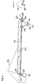
- Figure 1 shows a side view of the boom system of the crane according to the invention.
- a luffing jib 30 is articulated so that it can be luffed about a horizontal luffing axis via a joint 20.
- a jib guy rope 70 runs from the crane tower 10 over the top of the crane to the boom 30. By operating the jib guy rope 70, the jib 30 can be adjusted in the vertical luffing plane.
- the illustrated crane structure permits crane operation in luffing mode, that is to say with a luffing jib 30, as well as trolley operation.
- the hoist rope 40 is used for both modes.
- the trolley mode the trolley 60 is available, which can be moved in the longitudinal axis of the boom 30 relative to this.
- a pair of rope pulleys 62, 62b is arranged on the trolley 60 and the hook block 61, whereby a 2-leg operation of the hoist rope is made possible during the trolley mode.
- a trolley drive which comprises the two driven rope pulleys 63 and the associated stranding 64.
- the hoist rope 40 runs from the base of the tower via the boom pivot point to the boom tip.
- the hoist rope is steered over the pulley 51 and extends horizontally below the boom 30 in the direction of the boom tip.
- the hoist rope 40 is guided through the rope pulley pairs 62a, 62b of the trolley 60 or the hook block 61 until it reaches the
- the boom tip is diverted by the rope reeving roller 80 and is firmly connected to the boom structure at the end in the region of the boom tip.
- the view X shows a front view of the boom tip.
- the rope reeving roller 80 is connected to the boom tip such that it can pivot about an axis 82 running parallel to the longitudinal axis of the boom.
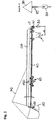
- the representation according to Figure 2 shows the crane configuration that is driven during luffing mode.
- the trolley 60 is fixed to the transport or dismantling lock 130, which is provided anyway, and is held against a movement in the direction of the longitudinal axis of the boom 30.
- the hoisting rope fixed point is released in the area of the boom tip.
- the end of the hoist rope 40 is connected to a hook block 90 provided for the luffing operation or is locked to it.
- the hoist rope 40 is still guided through the deflection pulleys 62a, 62b of the trolley 60 or the hook block 61, but this has no effect on the crane operation in the luffing mode.
- the reeving roller 80 is used as a deflection roller in order to deflect the hoist rope at the boom tip to the hook block 90.
- the view X of the Figure 2 also shows a front view of the boom tip.
- the rope reeving roller / deflection roller 80 hangs vertically on the boom tip with a horizontal axis of rotation.
- the trolley is not locked at the jib tip, but in a position that is favorable in terms of its own weight further inward near the tower 10, which leads to an increase in the maximum crane load.
- the crane operation is switched from a 2-strand operation in the trolley mode to a 1-strand operation in the luffing mode. This frees up additional hoist rope length, which is particularly advantageous in the case of large hook heights with a steep jib position.
- the effective radius of the crane can be maximized during the luffing mode compared to the trolley operation.
- the trolley 60 cannot be moved completely to the boom tip due to the technical conditions.
- the maximum possible outreach of the trolley 60 or of the crane hook 61 is smaller by the distance ⁇ L from the jib tip.
- the hoist rope 40 is deflected directly at the jib tip with the aid of the deflection roller 80, whereby a gain in radius of ⁇ L is achieved.
- the system-related loss of effective radius during trolley mode is consequently avoided in luffing mode.
- the crane hook 90 for the luffing mode is set down at the target point on the ground while the trolley mode is still in place.
- the trolley 60 and its hook 61 are then locked in the dismantling position 130 on the boom 30.
- the boom tip With the boom 30 extended, the boom tip is lowered down to the ground level, so that the hoisting rope fixed point at the boom tip can be released from the ground.
- the loosened hoist rope 50, including the rope pulleys, is secured on the boom 30.
- the rope reeving roller 80 is dismantled and used as a deflection roller 80. The position of the rope reeving roller 80 on the boom can be varied in order to be able to provide optimal conditions for the luffing mode.
- the now free hoisting rope fixed point is locked on the hook 90 that is available.
- the hoist rope safety device is then released and the boom 30 is pulled up.
- one or more sensors are available on the crane that measure the local geometry on the boom system and derive the current setup status based on the measurement data. The result is communicated to the crane control or the crane operator.
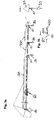
- Figure 3a shows schematically the possibility of extending the boom 30.
- a boom extension 100 such as a lattice jib, for example, can be mounted on the boom tip.
- other boom elements can also be introduced into the boom system to provide different functions. This offers the possibility of attaching individual elements or devices for displaying information to the boom tip.
- the method is then carried out up to the securing of the hoist rope 40.
- the boom extension 100 is then installed on the boom tip.
- the hoisting rope fixed point is connected to a safety rope 110 which extends to the tip of the boom extension 100.
- the safety rope 110 can be reeled onto a hand winch 120 around the hoisting rope from the boom tip to the outer one Pull out the end of the boom extension 100.
- the rope reeving roller 80 is dismantled at the boom tip and attached to the tip of the boom extension 100. Hoist rope 40 and reeving roller 80 are secured in the new position until boom 30 is erected.
- the rope reeving roller 80 mounted on the boom extension takes on the function of a deflection roller 80 for guiding the hoisting rope 40 to the crane hook 90.
- a sensor system detects the changed crane configuration and communicates this to the crane control.
- the invention enables the crane configuration to be changed quickly between trolley and luffing mode with little setup effort.
- the crane according to the invention and the method according to the invention ensure particularly flexible crane use on construction sites with particularly tight spaces.
Description
Die Erfindung betrifft ein Verfahren zum Betrieb eines Krans mit wippbarem Kranausleger und einer am Kranausleger verfahrbar angeordneten Laufkatze, wobei der Kran einerseits in einem Wippmodus und andererseits in einem Laufkatzmodus betreibbar ist. Die Erfindung betrifft des weiteren einen Kran, der wahlweise einen Kranbetrieb im Laufkatz- bzw. Wippmodus zulässt.The invention relates to a method for operating a crane with a luffing crane boom and a trolley movably arranged on the crane boom, the crane being operable on the one hand in a luffing mode and on the other hand in a trolley mode. The invention also relates to a crane which optionally allows crane operation in the trolley or luffing mode.
Aus dem Stand der Technik sind diverse Kransysteme bekannt, die je nach Anwendungsbereich gewisse Vorteile bieten. So sind Turmdrehkrane mit Katzausleger bekannt, bei denen der Ausleger stets eine horizontale Lage einnimmt und die Last mit Hilfe einer Laufkatze über die gesamte Auslegerlänge verfahrbar ist. Dies bietet den Vorteil, dass die angehängte Last besonders nahe an den Turm herangeführt werden kann.Various crane systems are known from the prior art, which offer certain advantages depending on the area of application. So tower cranes with trolley jibs are known in which the jib is always in a horizontal position and the load can be moved over the entire length of the jib with the aid of a trolley. This has the advantage that the suspended load can be brought particularly close to the tower.
Demgegenüber existieren Turmkrane mit Nadelausleger, die auch als Verstellausleger bezeichnet werden. Der Nadelausleger ist am Kranturm unterhalb der Turmspitze mit einem Gelenk befestigt sein und über ein Auslegerabspannseil in der Höhe veränderlich. Derartige Krane besitzen keine Laufkatze, die Last wird in Auslegerrichtung allein über die Hebe- und Senkbewegung des Auslegers transportiert. Die genannte Krankonstruktion bietet vor allem bei beengten Platzverhältnissen Vorteile, da der Ausleger zur Vermeidung von Kollisionen mit Hindernissen einfach "eingezogen" werden kann. Zudem kann die Last aufgrund der steileren Auslegerstellung auf größere Höhen angehoben werden.In contrast, there are tower cranes with luffing jibs, which are also referred to as adjustable booms. The luffing jib is attached to the crane tower below the top of the tower with a joint and can be adjusted in height via a jib guy rope. Such cranes do not have a trolley, the load is in the direction of the boom transported solely via the lifting and lowering movement of the boom. The above-mentioned crane construction offers advantages, especially in confined spaces, since the boom can simply be "pulled in" to avoid collisions with obstacles. In addition, due to the steeper boom position, the load can be lifted to greater heights.
Ein zunehmend hohes Maß an Flexibilität wird insbesondere von Mobilbaukranen erwartet, die einen verfahrbaren vollwertigen Turmdrehkran mit Katzausleger aufweisen. Dieser Kranaufbau soll oftmals unter komplexen räumlichen Bedingungen auf der Baustelle agieren, weshalb die vorgenannten Vorteile des Wippauslegersystems von großem Interesse sind.An increasingly high degree of flexibility is expected in particular from mobile construction cranes, which have a movable, full-fledged tower crane with a trolley jib. This crane structure should often operate under complex spatial conditions on the construction site, which is why the aforementioned advantages of the luffing jib system are of great interest.
In der Vergangenheit wurden bereits Bemühungen angestellt, die beiden vorgestellten Kransysteme miteinander zu verschmelzen. Insbesondere sollen die Vorteile der beiden unterschiedlichen Kransysteme in einem einzigen Kransystem vereint werden.Efforts have already been made in the past to merge the two crane systems presented. In particular, the advantages of the two different crane systems are to be combined in a single crane system.
Aus der
Die Lagerung der Laufkatze an der Auslegerspitze erhöht jedoch das Eigengewichtsmoment des Auslegersystems und reduziert folglich die mögliche Spitzentraglast im Wippbetrieb. Zudem geht durch die Einscherung des Hubseils an der Laufkatze Hubseillänge verloren, die gerade bei steilen Auslegerstellungen notwendig sein kann.However, the mounting of the trolley at the jib tip increases the dead weight of the boom system and consequently reduces the possible tip load capacity in luffing operation. In addition, due to the reeving of the hoist rope on the trolley, hoist rope length is lost, which can be necessary especially with steep jib positions.
Die
Die Aufgabe der vorliegenden Erfindung besteht darin, einen Kran bzw. ein Verfahren zum Betrieb eines Krans aufzuzeigen, mit dem sich die eingangs genannte Problematik überwinden lässt.The object of the present invention is to provide a crane or a method for operating a crane with which the problem mentioned at the beginning can be overcome.
Gelöst wird diese Aufgabe durch ein Verfahren zum Betrieb eines Krans gemäß den Merkmalen des Anspruchs 1. Vorteilhafte Ausführungsformen des erfindungsgemäßen Verfahrens sind Gegenstand der sich an den Hauptanspruch anschließenden Unteransprüche.This object is achieved by a method for operating a crane according to the features of claim 1. Advantageous embodiments of the method according to the invention are the subject matter of the subclaims that follow the main claim.
Anspruch 1 schlägt also ein Verfahren zum Betrieb eines Krans mit wippbarem Kranausleger und einer am Kranausleger verfahrbaren Laufkatze vor. Die Krankonfiguration gestattet zum einen den Kranbetrieb im Wippmodus und zum Anderen einen Betrieb im Laufkatzmodus. Der Kranoperator kann den anwendungsbedingt optimalen Kranmodus wählen und den Kran durch die Ausführung des Verfahrens zwischen den einzelnen Modi umrüsten.Claim 1 therefore proposes a method for operating a crane with a luffing crane boom and a trolley that can be moved on the crane boom. The crane configuration allows crane operation in luffing mode on the one hand and operation in trolley mode on the other. The crane operator can select the optimal crane mode for the application and convert the crane between the individual modes by executing the procedure.
Beispielsweise ist der Kran als Turmdrehkran, insbesondere als Mobilbaukran, ausgeführt, der einen Nadelausleger mit verfahrbarer Laufkatze umfasst.For example, the crane is designed as a tower crane, in particular as a mobile construction crane, which comprises a luffing jib with a movable trolley.
Bisher bekannte Konstruktionen aus dem Stand der Technik schlagen vor, die Laufkatze für den Wippmodus an der Auslegerspitze zu befestigen und den Kranhaken von der Laufkatze abzulassen. Die vorliegende Erfindung beschreitet nun einen in wesentlichen Punkten abweichenden Weg. Erfindungsgemäß wird die Einscherung des Hubseils am Auslegersystem verändert, so dass ein Wippbetrieb des Krans ermöglicht wird. Die Umlenkung des Hubseils vom Ausleger zum Kranhaken erfolgt damit unabhängig von der Laufkatze.Previously known constructions from the prior art propose to attach the trolley for the luffing mode to the jib tip and to lower the crane hook from the trolley. The present invention now takes a different approach in essential points. According to the invention, the reeving of the hoist rope on the boom system is changed so that a luffing operation of the crane is made possible. The deflection of the hoist rope from the boom to the crane hook is therefore independent of the trolley.
Die Umscherung eröffnet vor allem die Möglichkeit, die Laufkatze während des Wippbetriebes an einer beliebigen Stelle des Kranauslegers zu positionieren. Eine Lagerung an der Auslegerspitze ist nicht mehr zwingend notwendig, woraus sich gewisse Vorteile ergeben. Beispielsweise kann sich eine turmnahe Positionierung der Laufkatze günstig auf das Eigengewichtsmoment des Krans auswirken.Above all, the reeving opens up the possibility of positioning the trolley at any point on the crane jib during luffing operation. A storage at the boom tip is no longer absolutely necessary, which results in certain advantages. For example, positioning the trolley close to the tower can have a favorable effect on the crane's own weight moment.
Weiterhin kann durch eine günstige Wahl der Fixierungsposition der Laufkatze während des Wippmodus nicht nur eine Steigerung der Spitzentraglast sondern auch eine Erhöhung der effektiven Kranausladung erreicht werden. Der Verfahrweg der Laufkatze zur Auslegerspitze ist regelmäßig durch die technischen Gegebenheiten begrenzt, weshalb die theoretisch maximale Ausladung des Krans weder im Laufkatz- noch im Wippmodus optimal ausgeschöpft werden konnte. Aufgrund der erfindungsgemäßen Umscherung kann dieser Nachteil während des Wippmodus vermieden und die effektive Kranausladung erhöht werden.Furthermore, by a favorable choice of the fixation position of the trolley during the luffing mode, not only can the peak load-bearing capacity be increased, but also an increase in the effective crane radius can be achieved. The travel path of the trolley to the jib tip is regularly limited by the technical conditions, which is why the theoretical maximum radius of the crane could not be fully exploited in either the trolley or luffing mode. Due to the reeving according to the invention, this disadvantage can be avoided during the luffing mode and the effective crane radius can be increased.
Als besonders vorteilhaft erweist es sich, wenn durch die Umscherung ein Wechsel zwischen einem 1-Strang-Betrieb im Wippmodus und einem Mehr-Strang, insbesondere 2-Strang-Betrieb im Laufkatzmodus erfolgt. Durch die Umscherung des Hubseils in einen 1-Strang-Betrieb kann zusätzliche Hubseillänge gewonnen werden, die insbesondere bei steilen Auslegerstellungen im Wippmodus zur Geltung kommt.It proves to be particularly advantageous if the reeving results in a change between 1-leg operation in the luffing mode and a multi-leg, in particular 2-leg operation in the trolley mode. By reeving the hoist rope into 1-leg operation, additional hoist rope length can be gained, which is particularly useful in steep jib positions in luffing mode.
Während des Laufkatzmodus ist das Hubseil endseitig am Auslegersystem angeschlagen. Zur Änderung der Einscherung kann es vorteilhaft sein, wenn der Festpunkt des Hubseils für den Kranbetrieb im Wippmodus gelöst und an einem Lasthaken angeschlagen bzw. mit diesem verriegelt wird. Der Kran wird sodann im 1-Strang-Betrieb gefahren. Besonders zweckmäßig ist es, wenn für den Wippmodus ein gesonderter Lasthaken zur Verfügung steht.During the trolley mode, the end of the hoist rope is attached to the boom system. To change the reeving, it can be advantageous if the fixed point of the hoist rope for crane operation in luffing mode is released and attached to a load hook or locked with it. The crane is then operated in 1-line operation. It is particularly useful if a separate load hook is available for the luffing mode.
In einer besonders vorteilhaften Ausführungsform wird die Laufkatze und bzw. oder der verwendete Kranhaken/Hakenflasche des Katzmodus zum Betrieb im Wippmodus am Ausleger bzw. mit der Laufkatze verriegelt. Da bei der vorliegenden Erfindung die Verriegelung der Laufkatze nicht notwendigerweise an der Auslegerspitze erfolgen muss, wird eine bezüglich des Eigengewichtes der Laufkatze optimale Verriegelungsposition gewählt, die zweckmäßig beabstandet zur Auslegerspitze ist und das an der Auslegerspitze angreifende Eigengewichtmoment reduziert. Besonders vorteilhaft ist eine Verriegelung der Laufkatze in Nähe der Anlenkstelle des Auslegers.In a particularly advantageous embodiment, the trolley and / or the crane hook / hook block used in the trolley mode is locked on the boom or with the trolley for operation in the luffing mode. Since, in the present invention, the trolley does not necessarily have to be locked at the jib tip, an optimal locking position with respect to the dead weight of the trolley is selected, which is expediently spaced from the boom tip and reduces the dead weight torque acting on the boom tip. It is particularly advantageous to lock the trolley in the vicinity of the articulation point of the boom.
In diesem Fall kann es vorteilhaft sein, eine ohnehin vorhandene Transport- bzw. Demontageposition für die Laufkatze zu nutzen um diese während des Wippmodus am Ausleger zu verriegeln. Diese Transport- bzw. Demontageposition für die Laufkatze ist regelmäßig im Bereich des Auslegeranlenkpunktes angeordnet.In this case it can be advantageous to use an already existing transport or dismantling position for the trolley in order to lock it on the boom during the luffing mode. This transport or dismantling position for the trolley is regularly arranged in the area of the boom articulation point.
Es bietet sich in einer vorteilhaften Ausführung der Erfindung an, eine während des Katzmodus vorgesehene Seileinscherungsrolle während des Wippmodus als Umlenkrolle zu verwenden. Die Seileinscherungsrolle ist regelmäßig an der Auslegerspitze angeordnet und dient zur Fixierung bzw. Lagerung des Hubseils an der Auslegerspitze während des Laufkatzmodus. Denkbar ist es, dass die Position der Seileinscherungsrolle für den Wippmodus gezielt örtlich verändert wird, um eine optimale Umlenkung des Hubseils gewährleisten zu können.In an advantageous embodiment of the invention, it is advisable to use a rope reeving roller provided during the trolley mode as a deflection roller during the luffing mode. The rope reeving roller is regularly arranged at the jib tip and is used to fix or support the hoist rope at the jib tip during the trolley mode. It is conceivable that the position of the rope reeving roller for the luffing mode is specifically changed locally in order to be able to ensure an optimal deflection of the hoist rope.
Für die Umscherung ist es von Vorteil, wenn die Auslegerspitze bis in Bodennähe abgelassen wird. In diesem Fall kann die Umscherung bequem und ohne großen Aufwand vom Boden aus durch den Kranbediener vorgenommen werden. Bevorzugt wird die Auslegerspitze mit gestrecktem Ausleger bis in Bodennähe abgelassen.For reeving, it is advantageous if the boom tip is lowered to close to the ground. In this case, the reeving can be carried out comfortably and without great effort by the crane operator from the ground. The boom tip is preferably lowered to the ground level with the boom extended.
Für den Umschervorgang bei abgelassenem Ausleger ist es zweckmäßig, das Hubseil aus Sicherheitsgründen mit ein oder mehreren Sicherungsmitteln am Kranausleger zu sichern. Die Sicherung wird vorzugsweise vor bzw. kurz nach dem Lösen des Festpunktes des Hubseils am Auslegersystem angelegt. Vor der Aufnahme des gewünschten Kranbetriebs wird das Hubseil wieder entsichert.For the reeving process with the boom lowered, it is advisable to secure the hoist rope with one or more securing devices on the crane boom for safety reasons. The safety device is preferably applied before or shortly after the fixed point of the hoist rope is loosened on the boom system. Before starting the desired crane operation, the hoist rope is unlocked again.
Bevorzugt kann eine schnelle und einfache Möglichkeit vorgesehen sein, variabel ein oder mehrere Zusatzelemente am Ausleger, insbesondere der Auslegerspitze anzubringen. Ein oder mehrere Auslegerelemente können insbesondere zur Verlängerung des Auslegers zur Vergrößerung der nutzbaren Auslegerlänge montiert werden. Denkbar ist jedoch ebenfalls die Integration anderweitiger Auslegerelemente, die zusätzliche Funktionen am Auslegersystem bieten. Beispielsweise können einzelne Elemente oder Vorrichtungen zur Anzeige von Informationen an der Auslegerspitze angebracht werden. Ebenfalls ist eine Kombination dieser Elemente mit Auslegerverlängerungen denkbar.A quick and simple possibility can preferably be provided of variably attaching one or more additional elements to the boom, in particular the boom tip. One or more boom elements can be mounted in particular to extend the boom to increase the usable boom length. However, the integration of other boom elements that offer additional functions on the boom system is also conceivable. For example, individual elements or devices for displaying information on the Boom tip can be attached. A combination of these elements with boom extensions is also conceivable.
Die Einbindung ein oder mehrerer Auslegerelemente wird durch das Herablassen der Auslegerspitze in Bodennähe vereinfacht. Auch kann der Ausleger gezielt für den Wippmodus verlängert werden, was in der genannten schnellen und einfachen Weise bei bekannten Katzauslegerkranen aufgrund der Komplexität der Laufkatzenkonstruktion ohne weiteren Aufwand nicht möglich ist.The integration of one or more boom elements is simplified by lowering the boom tip close to the ground. The jib can also be specifically lengthened for the luffing mode, which is not possible without further effort in the quick and simple manner mentioned in known trolley jib cranes due to the complexity of the trolley construction.
Werden ein oder mehrere Auslegerelemente für den Wippmodus an der Auslegerspitze montiert, so wird der Hubseilfestpunkt gelöst und mit Hilfe eines Sicherungsseils bis zu einem der zusätzlichen Auslegerelemente, insbesondere bis zur Spitze des äußeren zusätzlichen Auslegerelementes herausgezogen. Vorzugsweise wird hierzu das Sicherungsseil von der äußeren Spitze des äußersten zusätzlichen Auslegerelementes bis hin zum Hubseilfestpunkt geführt.If one or more jib elements for the luffing mode are mounted on the jib tip, the hoisting rope fixed point is released and pulled out with the aid of a safety rope to one of the additional jib elements, in particular to the tip of the outer additional jib element. For this purpose, the safety rope is preferably guided from the outer tip of the outermost additional boom element to the hoisting rope fixed point.
Für den Wippmodus wird das Hubseil zweckmäßig mit einer an dem zusätzlichen Auslegerelement angebrachten Umlenkrolle umgelenkt und mit dem entsprechenden Kranhaken endseitig verbunden.For the luffing mode, the hoist rope is expediently deflected with a pulley attached to the additional boom element and connected at the end to the corresponding crane hook.
Besonders vorteilhaft ist es, wenn die Seileinscherungsrolle während des Katzmodus am ursprünglichen Ausleger demontiert und am entsprechenden zusätzlichen Auslegerelement für die Umlenkung des Hubseils montiert wird.It is particularly advantageous if the rope reeving roller is dismantled on the original boom during the trolley mode and mounted on the corresponding additional boom element for deflecting the hoist rope.
Der Hubseilfestpunkt wird vorzugsweise mit einer Handwinde bis zur Spitze des wenigstens einen zusätzlichen Auslegerelementes gezogen.The hoisting rope fixed point is preferably pulled with a hand winch to the tip of the at least one additional boom element.
Ein oder mehrere Sensoren können die örtliche Geometrie der aktuellen Krankonfiguration erfassen und somit den geplanten Kranmodus, das heißt den Wipp- bzw. Katzmodus automatisch erkennen. Die Kransteuerung kann folglich unter Berücksichtigung des erkannten Kranmodus arbeiten und entsprechende Krankommandos bzw. Funktionen freischalten bzw. ausführen.One or more sensors can detect the local geometry of the current crane configuration and thus automatically recognize the planned crane mode, i.e. the luffing or trolley mode. The crane control can consequently work taking into account the recognized crane mode and enable or execute corresponding crane commands or functions.
Die Erfindung betrifft weiterhin einen Kran, insbesondere einen Turmdrehkran oder Mobilbaukran, mit wippbarem Kranausleger, insbesondere Nadelausleger, und einer am Kranausleger verfahrbar angeordneten Laufkatze. Die vorgeschlagene Krankonfiguration erlaubt es, den Kran einerseits in einem Wippmodus und andererseits in einem Laufkatzmodus zu betreiben.The invention further relates to a crane, in particular a tower crane or mobile construction crane, with a luffing crane boom, in particular a luffing jib, and a trolley that is movably arranged on the crane boom. The proposed crane configuration allows the crane to be operated on the one hand in a luffing mode and on the other hand in a trolley mode.
Erfindungsgemäß ist das Hubseil des Krans im Wippbetrieb über wenigstens eine Umlenkrolle am Kranausleger, insbesondere der Auslegerspitze geführt und endseitig an einem Lasthaken angeschlagen bzw. mit diesem verriegelt. Der Kran zeichnet sich erfindungsgemäß dadurch aus, dass während des Wippmodus ein 1-Strang-Betrieb des Hubseils gewährleistet ist, wohingegen während des bekannten Laufkatzmodus in der Regel eine mehrfache Einscherung des Hubseils notwendig ist.According to the invention, the hoist rope of the crane in luffing operation is guided over at least one pulley on the crane boom, in particular the boom tip, and is attached to a load hook at the end or is locked to it. According to the invention, the crane is characterized in that 1-leg operation of the hoist rope is ensured during the luffing mode, whereas multiple reeving of the hoist rope is usually necessary during the known trolley mode.
Durch die 1-Strang-Führung des Hubseils während des Wippmodus ergeben sich gewissen Vorteile. Beispielsweise ist die Position der Laufkatze für die Funktion des Krans im Wippmodus unerheblich, eine Positionierung in Nähe des Auslegeranlenkpunktes ist daher möglich. Weiterhin steht durch den 1-Strang-Betrieb eine größere Hubseilmenge zur Verfügung.The 1-strand guidance of the hoist rope during the luffing mode results in certain advantages. For example, the position of the trolley is irrelevant for the function of the crane in the luffing mode, so it can be positioned in the vicinity of the boom articulation point. Furthermore, a larger amount of hoisting ropes is available due to the 1-line operation.
Zudem umfasst der erfindungsgemäße Kran vorteilhafterweise Mittel zur Durchführung des erfindungsgemäßen Verfahren bzw. einer vorteilhaften Ausgestaltung des erfindungsgemäßen Verfahrens. Die Vorteile und Eigenschaften des erfindungsgemäßen Krans entsprechen offensichtlich denen des erfindungsgemäßen Verfahrens, weshalb an dieser Stelle auf eine wiederholende Beschreibung verzichtet wird.In addition, the crane according to the invention advantageously comprises means for carrying out the method according to the invention or an advantageous embodiment of the method according to the invention. The advantages and properties of the crane according to the invention obviously correspond to those of the method according to the invention, which is why a repetitive description is dispensed with at this point.
Weitere Vorteile und Eigenschaften der Erfindung ergeben sich aus einem in den nachfolgenden Zeichnungen näher beschriebenen Ausführungsbeispiel. Es zeigen:
- Figur 1:
- eine schematische Seitenansicht des erfindungsgemäßen Krans während des Katzmodus,
- Figur 2:
- eine schematische Seitenansicht auf den Kran gemäß
Figur 1 im Wippmodus und - Figur 3:
- eine schematische Seitenansicht auf den Kran gemäß
Figur 2 mit verlängerter Auslegerspitze.
- Figure 1:
- a schematic side view of the crane according to the invention during the trolley mode,
- Figure 2:
- a schematic side view of the crane according to
Figure 1 in rocker mode and - Figure 3:
- a schematic side view of the crane according to
Figure 2 with extended boom tip.
Der dargestellte Kranaufbau lässt den Kranbetrieb im Wippmodus, also mit wippbarem Ausleger 30, als auch den Laufkatzbetrieb zu. Für beide Modi wird das Hubseil 40 verwendet. Für den Katzmodus steht die Laufkatze 60 zur Verfügung, die in Längsachse des Auslegers 30 relativ zu diesem verfahrbar ist. Jeweils ein Seilrollenpaar 62, 62b ist an der Laufkatze 60 sowie der Hakenflasche 61 angeordnet, wodurch ein 2-Strang-Betrieb des Hubseils während des Laufkatzmodus ermöglicht wird.The illustrated crane structure permits crane operation in luffing mode, that is to say with a luffing
Zum Verfahren der Laufkatze 60 ist ein Katzantrieb vorgesehen, der die beiden angetriebenen Seilrollen 63 sowie die dazugehörige Verseilung 64 umfasst.To move the
Das Hubseil 40 verläuft vom Turmfuss über den Auslegeranlenkpunkt bis hin zur Auslegerspitze. Im Auslegeranlenkbereich wird das Hubseil über die Seilrolle 51 gelenkt und erstreckt sich horizontal unterhalb des Auslegers 30 in Richtung der Auslegerspitze. Wie bereits beschrieben wird das Hubseil 40 durch die Seilrollenpaare 62a, 62b der Laufkatze 60 bzw. der Hakenflasche 61 geführt bis es an der Auslegerspitze durch die Seileinscherungsrolle 80 umgeleitet und endseitig im Bereich der Auslegerspitze fest mit der Auslegerstruktur verbunden wird. Die Ansicht X zeigt eine Vorderansicht auf die Auslegerspitze. Die Seileinscherungsrolle 80 ist über um eine parallel zur Auslegerlängsachse verlaufende Achse 82 schwenkbar mit der Auslegerspitze verbunden.The hoist
Die Darstellung gemäß
Im Bereich der Auslegerspitze wird die Einscherungsrolle 80 als Umlenkrolle verwendet um das Hubseil an der Auslegerspitze zur Hakenflasche 90 umzulenken. Die Ansicht X der
Die Laufkatze wird nicht an der Auslegerspitze verriegelt, sondern in einer bezüglich ihres Eigengewichts günstigen Position weiter innen in Nähe des Turms 10, was zu einer Steigerung der maximalen Krantraglast führt. Durch die Umscherung des Hubseils 40 für den Wippmodus wird der Kranbetrieb von einem 2-Strang-Betrieb im Laufkatzmodus in einen 1-Strang-Betrieb im Wippmodus umgestellt. Hierdurch wird zusätzliche Hubseillänge frei, die insbesondere bei großen Hakenhöhen mit einer steilen Auslegerstellung von Vorteil ist.The trolley is not locked at the jib tip, but in a position that is favorable in terms of its own weight further inward near the
Zudem kann die effektive Ausladung des Krans während des Wippmodus gegenüber dem Laufkatzbetrieb maximiert werden. Wie die gestrichelten Konturen in Figur 2 andeuten, lässt sich die Laufkatze 60 aufgrund der technischen Gegebenheiten nicht vollständig bis zur Auslegerspitze verfahren. Die maximal mögliche Ausladung der Laufkatze 60 bzw. des Kranhakens 61 fällt um den Abstand ΔL zur Auslegerspitze geringer aus.In addition, the effective radius of the crane can be maximized during the luffing mode compared to the trolley operation. Like the dashed contours in figure 2 indicate, the
Durch die Änderung der Krankonfiguration im Wippmodus wird das Hubseil 40 mit Hilfe der Umlenkrolle 80 direkt an der Auslegerspitze umgelenkt, wodurch ein Ausladungsgewinn von ΔL erreicht wird. Der systembedingte Verlust an Effektivausladung während des Katzmodus wird folglich im Wippmodus vermieden.By changing the crane configuration in the luffing mode, the hoist
Für die Änderung der Krankonfiguration ausgehend vom Katzmodus zum Wippmodus sind die folgenden einzelnen Verfahrensschritte notwendig:
Zu Anfang wird der Kranhaken 90 für den Wippmodus noch während des Katzmodus an der Zielstelle am Boden abgesetzt. Im Anschluss werden die Laufkatze 60 sowie deren Haken 61 in der Demontageposition 130 am Ausleger 30 verriegelt. Die Auslegerspitze wird mit gestrecktem Ausleger 30 bis in Bodennähe abgelassen, so dass der Hubseilfestpunkt an der Auslegerspitze vom Boden aus gelöst werden kann. Das gelöste Hubseil 50 wird inklusive der Seilrollen am Ausleger 30 gesichert. Die Seileinscherungsrolle 80 wird demontiert als Umlenkrolle 80 genutzt. Dabei kann die Position der Seileinscherungsrolle 80 am Ausleger variiert werden, um optimale Bedingungen für den Wippmodus bereitstellen zu können.To change the crane configuration from trolley mode to luffing mode, the following individual process steps are necessary:
At the beginning, the
Der nun freie Hubseilfestpunkt wird am bereitstehenden Haken 90 verriegelt. Im Anschluss wird die Hubseilsicherung gelöst und der Ausleger 30 hochgezogen.The now free hoisting rope fixed point is locked on the
Zusätzlich stehen ein oder mehrere Sensoren am Kran zur Verfügung, die die örtliche Geometrie am Auslegersystem messen und den aktuellen Rüstzustand anhand der Messdaten ableiten. Das Ergebnis wird der Kransteuerung bzw. dem Kranbediener mitgeteilt.In addition, one or more sensors are available on the crane that measure the local geometry on the boom system and derive the current setup status based on the measurement data. The result is communicated to the crane control or the crane operator.
Für die Änderung der Krankonfiguration vom Wippmodus zum Katzmodus werden die voranstehend beschriebenen Verfahrensschritte in umgekehrter Reihenfolge ausgeführt.To change the crane configuration from luffing mode to trolley mode, the method steps described above are carried out in reverse order.
Durch die Änderung der Krankonfiguration, insbesondere der Änderung der Hubseileinscherung ergibt sich eine einfache Möglichkeit, die Auslegerkonfiguration während des Umbaus zu verändern. Während der Umscherung des Hubseils 40 können bei abgelassenem Ausleger 30 ein oder mehrere Zusatzelemente zur Verlängerung des Auslegers 30 besonders einfach und schnell an der Auslegerspitze montiert werden.By changing the crane configuration, in particular changing the hoisting rope reeving, there is a simple possibility of changing the boom configuration during the conversion. During the reeving of the hoist
Für die Montage einer Auslegerverlängerung bzw. eines zusätzlichen Auslegerelementes wird auf das voranstehend beschriebene Verfahren zum Moduswechsel zurückgegriffen. Vorab wird jedoch zusätzlich zum Kranhaken 90 wenigstens eine Verlängerung 100 bzw. ein Zusatzelement bereitgestellt.For the assembly of a boom extension or an additional boom element, the method described above for changing modes is used. However, in addition to the
Im Anschluss wird das Verfahren bis zur Sicherung des Hubseils 40 ausgeführt. Im Anschluss erfolgt die Montage der Auslegerverlängerung 100 an der Auslegerspitze. Wie in der Detailansicht gemäß
Die Erfindung ermöglicht mit wenig Rüstaufwand eine rasche Änderung der Krankonfiguration zwischen Katz- und Wippmodus. Der erfindungsgemäße Kran bzw. das erfindungsgemäße Verfahren gewährleistet einen besonders flexiblen Kraneinsatz auf Baustellen mit besonders beengten Platzverhältnissen.The invention enables the crane configuration to be changed quickly between trolley and luffing mode with little setup effort. The crane according to the invention and the method according to the invention ensure particularly flexible crane use on construction sites with particularly tight spaces.
Claims (13)
- Method of operating a crane having a luffable crane boom (30) and having a trolley (60) arranged travelable at the crane boom (30), wherein the crane can be operated in a luffing mode, on the one hand, and in a trolley mode, on the other hand,characterized in thata change of the hoist rope reeving takes place on a single hoist rope (40) for a mode change.
- Method in accordance with claim 1, characterized in that a one-line operation takes place in the luffing mode and a multi-line operation, in particular a two-line operation, of the hoist rope (40) takes place in the trolley mode.
- Method in accordance with one of the preceding claims, characterized in that the required fixed point of the hoist rope (40) is released for the crane operation in the luffing mode during the trolley mode and is beaten up or latched at a load hook (90).
- Method in accordance with one of the preceding claims, characterized in that the trolley (60) and/or the crane hook/hook block (61) of the trolley mode is/are latched to the boom (30) during the luffing mode, in particular is/are latched spaced apart from the boom tip at a position favorable with respect to its unloaded weight.
- Method in accordance with claim 4, characterized in that the trolley (60) or the crane hook/hook block (61) of the trolley (60) is/are latched in its transport/dismantling position, in particular in the region of the boom pivotal connection point (20).
- Method in accordance with one of the preceding claims, characterized in that the hoist rope (40) is fixed to the boom (30) in the trolley mode, wherein the rope reeving pulley (80) is used as a deflection pulley in the luffing mode, and wherein the position of the pulley (80) or of the support preferably is locally changeable.
- Method in accordance with one of the preceding claims, characterized in that the boom tip is let down, in particular with an extended boom (30), to close to the ground for re-reeving the hoist rope (40) for the corresponding crane mode.
- Method in accordance with one of the preceding claims, characterized in that the hoist rope (40) is optionally secured together with hoist rope pulleys after the release of the fixing point up to the starting of the luffing operation at the crane boom (30).
- Method in accordance with one of the preceding claims, characterized in that at least one additional boom element (100) for the luffing mode is mounted during the hoist rope re-reeving, wherein the hoist rope fixing point is connected to a securing rope (110) starting from the at least one additional boom element (100) and is pulled out up to the tip of the extension (100).
- Method in accordance with claim 9, characterized in that the hoist rope fixing point is pulled with a hand winch (120) up to the tip of the at least one additional boom element (100).
- Method in accordance with one of the preceding claims, characterized in that one or more sensors recognize the operating mode of the crane due to the local geometry.
- Crane, in particular a revolving tower crane or a mobile construction crane, comprising a hoist rope (40), a luffable crane boom (30) and a trolley (60) arranged travelable at the crane boom (30), wherein the crane can be operated in a luffing mode, on the one hand, and in a trolley mode, on the other hand,characterized in thatthe hoist rope (40) is used for both the luffing mode and the trolley mode, wherein the hoist rope (40) in the luffing operation is guided via at least one deflection pulley (80) at the crane boom (30), in particular the boom tip, and is beaten up at the end side to a load hook (90) or is latched thereto.
- Crane in accordance with claim 12 for carrying out the method in accordance with one of the claims 1 to 11.
Applications Claiming Priority (2)
| Application Number | Priority Date | Filing Date | Title |
|---|---|---|---|
| DE102012018392.5A DE102012018392A1 (en) | 2012-09-18 | 2012-09-18 | Method of operating a crane and crane |
| PCT/EP2013/002816 WO2014044391A1 (en) | 2012-09-18 | 2013-09-18 | Method for operating a crane, and crane |
Publications (2)
| Publication Number | Publication Date |
|---|---|
| EP2897892A1 EP2897892A1 (en) | 2015-07-29 |
| EP2897892B1 true EP2897892B1 (en) | 2021-11-10 |
Family
ID=49230689
Family Applications (1)
| Application Number | Title | Priority Date | Filing Date |
|---|---|---|---|
| EP13765952.0A Active EP2897892B1 (en) | 2012-09-18 | 2013-09-18 | Method for operating a crane, and crane |
Country Status (7)
| Country | Link |
|---|---|
| US (1) | US9745175B2 (en) |
| EP (1) | EP2897892B1 (en) |
| CN (1) | CN104781182B (en) |
| DE (1) | DE102012018392A1 (en) |
| ES (1) | ES2905225T3 (en) |
| IN (1) | IN2015DN02813A (en) |
| WO (1) | WO2014044391A1 (en) |
Families Citing this family (3)
| Publication number | Priority date | Publication date | Assignee | Title |
|---|---|---|---|---|
| DE102015211612B3 (en) * | 2015-06-23 | 2016-11-24 | Tadano Faun Gmbh | Telescopic boom for a crane |
| CN108328486A (en) * | 2018-04-23 | 2018-07-27 | 湖南格林美映鸿资源循环有限公司 | A kind of pillar (rotary, revolving) crane and lifting equipment |
| CN109795958A (en) * | 2019-03-26 | 2019-05-24 | 贵州航天建设工程有限公司 | A kind of safe tower crane system and method for safe operation based on fence |
Family Cites Families (10)
| Publication number | Priority date | Publication date | Assignee | Title |
|---|---|---|---|---|
| FR1007775A (en) * | 1948-03-30 | 1952-05-09 | Articulating boom lifting device | |
| FR1170104A (en) * | 1950-05-13 | 1959-01-09 | Chantiers Et Ateliers De Const | Tower crane operating with trolley or with luffing jib |
| FR1045440A (en) * | 1950-11-24 | 1953-11-26 | British Hoist And Crane Compan | Improvements to cranes |
| DE1171132B (en) | 1961-05-02 | 1964-05-27 | Reich Fa Wilhelm | Tower crane with retractable boom and trolley guided on this |
| DE3232489A1 (en) * | 1982-09-01 | 1984-03-01 | Blohm + Voss Ag, 2000 Hamburg | SHIP LOADING TREE |
| CN87200092U (en) * | 1987-01-09 | 1987-11-04 | 中国建筑第二工程局建筑科学技术研究所 | Elevator type tower crane |
| CN2033001U (en) * | 1988-07-02 | 1989-02-22 | 孙国栋 | Tower crane with base following storey rising |
| DE4447384A1 (en) * | 1994-12-22 | 1996-06-27 | Mannesmann Ag | Mobile crane, in particular mobile harbor crane |
| US20030160016A1 (en) * | 2002-02-28 | 2003-08-28 | Eduardo Ortiz | Mobile tower crane |
| US20120223042A1 (en) * | 2011-03-01 | 2012-09-06 | All Metal Ms, Corporation | System, method and apparatus for lifting a component from a helicopter in the field |
-
2012
- 2012-09-18 DE DE102012018392.5A patent/DE102012018392A1/en not_active Ceased
-
2013
- 2013-09-18 EP EP13765952.0A patent/EP2897892B1/en active Active
- 2013-09-18 WO PCT/EP2013/002816 patent/WO2014044391A1/en active Application Filing
- 2013-09-18 CN CN201380057106.9A patent/CN104781182B/en active Active
- 2013-09-18 ES ES13765952T patent/ES2905225T3/en active Active
- 2013-09-18 US US14/429,349 patent/US9745175B2/en active Active
-
2015
- 2015-04-06 IN IN2813DEN2015 patent/IN2015DN02813A/en unknown
Non-Patent Citations (1)
| Title |
|---|
| None * |
Also Published As
| Publication number | Publication date |
|---|---|
| US20150375972A1 (en) | 2015-12-31 |
| WO2014044391A1 (en) | 2014-03-27 |
| ES2905225T3 (en) | 2022-04-07 |
| CN104781182B (en) | 2017-09-22 |
| CN104781182A (en) | 2015-07-15 |
| IN2015DN02813A (en) | 2015-09-11 |
| US9745175B2 (en) | 2017-08-29 |
| EP2897892A1 (en) | 2015-07-29 |
| DE102012018392A1 (en) | 2014-03-20 |
Similar Documents
| Publication | Publication Date | Title |
|---|---|---|
| EP2364948B1 (en) | Crane | |
| EP2426077B1 (en) | Crane | |
| EP2435352B1 (en) | Traveling crane having traveler and hoisting winch | |
| DE102010020016B4 (en) | Crane and method of erecting the crane | |
| DE102009048846A1 (en) | crane | |
| DE3838975C2 (en) | ||
| DE202010003269U1 (en) | crane | |
| DE102014204874A1 (en) | Cylinder entry system, delivery device and crawler crane | |
| EP2455322A1 (en) | Crane | |
| DE102014012661B4 (en) | Method of operating a crane and crane | |
| EP2897892B1 (en) | Method for operating a crane, and crane | |
| AT523743A2 (en) | Mobile crane and method of reducing the load on its boom | |
| EP2423147B1 (en) | Assembly for rotating a load | |
| EP2693045A1 (en) | Access system for performing inspection and maintenance work on tower-like structures | |
| DE3018560C2 (en) | ||
| DE202011001850U1 (en) | crane | |
| DE202004002424U1 (en) | Derrick | |
| DE102012002040B4 (en) | Method of operating a crane and crane | |
| EP1568649B1 (en) | Cable crane | |
| DE1406305C3 (en) | Construction crane | |
| DE10113561A1 (en) | Pile-driving or drilling device comprises a supporting device, a carriage with a work tool, and a sliding device having a gypsy winch operating a cable connected to the carriage | |
| EP3645913B1 (en) | Arrangement with two energy guide chains and adjustable fixed point | |
| DE976018C (en) | Tower crane with a tower that can be erected around a horizontal axis of the crane carriage | |
| EP1947051A2 (en) | Elevation cable tackle system | |
| EP2690053B1 (en) | Safety device for a working machine. |
Legal Events
| Date | Code | Title | Description |
|---|---|---|---|
| PUAI | Public reference made under article 153(3) epc to a published international application that has entered the european phase |
Free format text: ORIGINAL CODE: 0009012 |
|
| 17P | Request for examination filed |
Effective date: 20150324 |
|
| AK | Designated contracting states |
Kind code of ref document: A1 Designated state(s): AL AT BE BG CH CY CZ DE DK EE ES FI FR GB GR HR HU IE IS IT LI LT LU LV MC MK MT NL NO PL PT RO RS SE SI SK SM TR |
|
| AX | Request for extension of the european patent |
Extension state: BA ME |
|
| DAX | Request for extension of the european patent (deleted) | ||
| STAA | Information on the status of an ep patent application or granted ep patent |
Free format text: STATUS: EXAMINATION IS IN PROGRESS |
|
| 17Q | First examination report despatched |
Effective date: 20171011 |
|
| STAA | Information on the status of an ep patent application or granted ep patent |
Free format text: STATUS: EXAMINATION IS IN PROGRESS |
|
| GRAP | Despatch of communication of intention to grant a patent |
Free format text: ORIGINAL CODE: EPIDOSNIGR1 |
|
| STAA | Information on the status of an ep patent application or granted ep patent |
Free format text: STATUS: GRANT OF PATENT IS INTENDED |
|
| INTG | Intention to grant announced |
Effective date: 20210601 |
|
| RAP3 | Party data changed (applicant data changed or rights of an application transferred) |
Owner name: LIEBHERR-WERK BIBERACH GMBH |
|
| GRAS | Grant fee paid |
Free format text: ORIGINAL CODE: EPIDOSNIGR3 |
|
| GRAA | (expected) grant |
Free format text: ORIGINAL CODE: 0009210 |
|
| STAA | Information on the status of an ep patent application or granted ep patent |
Free format text: STATUS: THE PATENT HAS BEEN GRANTED |
|
| AK | Designated contracting states |
Kind code of ref document: B1 Designated state(s): AL AT BE BG CH CY CZ DE DK EE ES FI FR GB GR HR HU IE IS IT LI LT LU LV MC MK MT NL NO PL PT RO RS SE SI SK SM TR |
|
| REG | Reference to a national code |
Ref country code: GB Ref legal event code: FG4D Free format text: NOT ENGLISH |
|
| REG | Reference to a national code |
Ref country code: AT Ref legal event code: REF Ref document number: 1445926 Country of ref document: AT Kind code of ref document: T Effective date: 20211115 Ref country code: CH Ref legal event code: EP |
|
| REG | Reference to a national code |
Ref country code: DE Ref legal event code: R096 Ref document number: 502013015981 Country of ref document: DE |
|
| REG | Reference to a national code |
Ref country code: IE Ref legal event code: FG4D Free format text: LANGUAGE OF EP DOCUMENT: GERMAN |
|
| REG | Reference to a national code |
Ref country code: NL Ref legal event code: FP |
|
| REG | Reference to a national code |
Ref country code: LT Ref legal event code: MG9D |
|
| REG | Reference to a national code |
Ref country code: ES Ref legal event code: FG2A Ref document number: 2905225 Country of ref document: ES Kind code of ref document: T3 Effective date: 20220407 |
|
| PG25 | Lapsed in a contracting state [announced via postgrant information from national office to epo] |
Ref country code: RS Free format text: LAPSE BECAUSE OF FAILURE TO SUBMIT A TRANSLATION OF THE DESCRIPTION OR TO PAY THE FEE WITHIN THE PRESCRIBED TIME-LIMIT Effective date: 20211110 Ref country code: LT Free format text: LAPSE BECAUSE OF FAILURE TO SUBMIT A TRANSLATION OF THE DESCRIPTION OR TO PAY THE FEE WITHIN THE PRESCRIBED TIME-LIMIT Effective date: 20211110 Ref country code: FI Free format text: LAPSE BECAUSE OF FAILURE TO SUBMIT A TRANSLATION OF THE DESCRIPTION OR TO PAY THE FEE WITHIN THE PRESCRIBED TIME-LIMIT Effective date: 20211110 Ref country code: BG Free format text: LAPSE BECAUSE OF FAILURE TO SUBMIT A TRANSLATION OF THE DESCRIPTION OR TO PAY THE FEE WITHIN THE PRESCRIBED TIME-LIMIT Effective date: 20220210 |
|
| PG25 | Lapsed in a contracting state [announced via postgrant information from national office to epo] |
Ref country code: IS Free format text: LAPSE BECAUSE OF FAILURE TO SUBMIT A TRANSLATION OF THE DESCRIPTION OR TO PAY THE FEE WITHIN THE PRESCRIBED TIME-LIMIT Effective date: 20220310 Ref country code: SE Free format text: LAPSE BECAUSE OF FAILURE TO SUBMIT A TRANSLATION OF THE DESCRIPTION OR TO PAY THE FEE WITHIN THE PRESCRIBED TIME-LIMIT Effective date: 20211110 Ref country code: PT Free format text: LAPSE BECAUSE OF FAILURE TO SUBMIT A TRANSLATION OF THE DESCRIPTION OR TO PAY THE FEE WITHIN THE PRESCRIBED TIME-LIMIT Effective date: 20220310 Ref country code: PL Free format text: LAPSE BECAUSE OF FAILURE TO SUBMIT A TRANSLATION OF THE DESCRIPTION OR TO PAY THE FEE WITHIN THE PRESCRIBED TIME-LIMIT Effective date: 20211110 Ref country code: NO Free format text: LAPSE BECAUSE OF FAILURE TO SUBMIT A TRANSLATION OF THE DESCRIPTION OR TO PAY THE FEE WITHIN THE PRESCRIBED TIME-LIMIT Effective date: 20220210 Ref country code: LV Free format text: LAPSE BECAUSE OF FAILURE TO SUBMIT A TRANSLATION OF THE DESCRIPTION OR TO PAY THE FEE WITHIN THE PRESCRIBED TIME-LIMIT Effective date: 20211110 Ref country code: HR Free format text: LAPSE BECAUSE OF FAILURE TO SUBMIT A TRANSLATION OF THE DESCRIPTION OR TO PAY THE FEE WITHIN THE PRESCRIBED TIME-LIMIT Effective date: 20211110 Ref country code: GR Free format text: LAPSE BECAUSE OF FAILURE TO SUBMIT A TRANSLATION OF THE DESCRIPTION OR TO PAY THE FEE WITHIN THE PRESCRIBED TIME-LIMIT Effective date: 20220211 |
|
| PG25 | Lapsed in a contracting state [announced via postgrant information from national office to epo] |
Ref country code: SM Free format text: LAPSE BECAUSE OF FAILURE TO SUBMIT A TRANSLATION OF THE DESCRIPTION OR TO PAY THE FEE WITHIN THE PRESCRIBED TIME-LIMIT Effective date: 20211110 Ref country code: SK Free format text: LAPSE BECAUSE OF FAILURE TO SUBMIT A TRANSLATION OF THE DESCRIPTION OR TO PAY THE FEE WITHIN THE PRESCRIBED TIME-LIMIT Effective date: 20211110 Ref country code: RO Free format text: LAPSE BECAUSE OF FAILURE TO SUBMIT A TRANSLATION OF THE DESCRIPTION OR TO PAY THE FEE WITHIN THE PRESCRIBED TIME-LIMIT Effective date: 20211110 Ref country code: EE Free format text: LAPSE BECAUSE OF FAILURE TO SUBMIT A TRANSLATION OF THE DESCRIPTION OR TO PAY THE FEE WITHIN THE PRESCRIBED TIME-LIMIT Effective date: 20211110 Ref country code: DK Free format text: LAPSE BECAUSE OF FAILURE TO SUBMIT A TRANSLATION OF THE DESCRIPTION OR TO PAY THE FEE WITHIN THE PRESCRIBED TIME-LIMIT Effective date: 20211110 Ref country code: CZ Free format text: LAPSE BECAUSE OF FAILURE TO SUBMIT A TRANSLATION OF THE DESCRIPTION OR TO PAY THE FEE WITHIN THE PRESCRIBED TIME-LIMIT Effective date: 20211110 |
|
| REG | Reference to a national code |
Ref country code: DE Ref legal event code: R097 Ref document number: 502013015981 Country of ref document: DE |
|
| PLBE | No opposition filed within time limit |
Free format text: ORIGINAL CODE: 0009261 |
|
| STAA | Information on the status of an ep patent application or granted ep patent |
Free format text: STATUS: NO OPPOSITION FILED WITHIN TIME LIMIT |
|
| 26N | No opposition filed |
Effective date: 20220811 |
|
| PG25 | Lapsed in a contracting state [announced via postgrant information from national office to epo] |
Ref country code: AL Free format text: LAPSE BECAUSE OF FAILURE TO SUBMIT A TRANSLATION OF THE DESCRIPTION OR TO PAY THE FEE WITHIN THE PRESCRIBED TIME-LIMIT Effective date: 20211110 |
|
| PG25 | Lapsed in a contracting state [announced via postgrant information from national office to epo] |
Ref country code: SI Free format text: LAPSE BECAUSE OF FAILURE TO SUBMIT A TRANSLATION OF THE DESCRIPTION OR TO PAY THE FEE WITHIN THE PRESCRIBED TIME-LIMIT Effective date: 20211110 |
|
| PG25 | Lapsed in a contracting state [announced via postgrant information from national office to epo] |
Ref country code: MC Free format text: LAPSE BECAUSE OF FAILURE TO SUBMIT A TRANSLATION OF THE DESCRIPTION OR TO PAY THE FEE WITHIN THE PRESCRIBED TIME-LIMIT Effective date: 20211110 |
|
| REG | Reference to a national code |
Ref country code: BE Ref legal event code: MM Effective date: 20220930 |
|
| PG25 | Lapsed in a contracting state [announced via postgrant information from national office to epo] |
Ref country code: LU Free format text: LAPSE BECAUSE OF NON-PAYMENT OF DUE FEES Effective date: 20220918 |
|
| PG25 | Lapsed in a contracting state [announced via postgrant information from national office to epo] |
Ref country code: IE Free format text: LAPSE BECAUSE OF NON-PAYMENT OF DUE FEES Effective date: 20220918 |
|
| P01 | Opt-out of the competence of the unified patent court (upc) registered |
Effective date: 20230630 |
|
| PG25 | Lapsed in a contracting state [announced via postgrant information from national office to epo] |
Ref country code: BE Free format text: LAPSE BECAUSE OF NON-PAYMENT OF DUE FEES Effective date: 20220930 |
|
| PGFP | Annual fee paid to national office [announced via postgrant information from national office to epo] |
Ref country code: NL Payment date: 20230921 Year of fee payment: 11 Ref country code: GB Payment date: 20230920 Year of fee payment: 11 Ref country code: AT Payment date: 20230919 Year of fee payment: 11 |
|
| PGFP | Annual fee paid to national office [announced via postgrant information from national office to epo] |
Ref country code: FR Payment date: 20230922 Year of fee payment: 11 Ref country code: DE Payment date: 20230928 Year of fee payment: 11 |
|
| PGFP | Annual fee paid to national office [announced via postgrant information from national office to epo] |
Ref country code: ES Payment date: 20231002 Year of fee payment: 11 |
|
| PGFP | Annual fee paid to national office [announced via postgrant information from national office to epo] |
Ref country code: IT Payment date: 20230927 Year of fee payment: 11 Ref country code: CH Payment date: 20231001 Year of fee payment: 11 |
|
| PG25 | Lapsed in a contracting state [announced via postgrant information from national office to epo] |
Ref country code: HU Free format text: LAPSE BECAUSE OF FAILURE TO SUBMIT A TRANSLATION OF THE DESCRIPTION OR TO PAY THE FEE WITHIN THE PRESCRIBED TIME-LIMIT; INVALID AB INITIO Effective date: 20130918 |